WO2020122188A1 - タイヤ摩耗検知装置 - Google Patents
タイヤ摩耗検知装置 Download PDFInfo
- Publication number
- WO2020122188A1 WO2020122188A1 PCT/JP2019/048737 JP2019048737W WO2020122188A1 WO 2020122188 A1 WO2020122188 A1 WO 2020122188A1 JP 2019048737 W JP2019048737 W JP 2019048737W WO 2020122188 A1 WO2020122188 A1 WO 2020122188A1
- Authority
- WO
- WIPO (PCT)
- Prior art keywords
- tire
- wear
- unit
- vibration
- road surface
- Prior art date
- Legal status (The legal status is an assumption and is not a legal conclusion. Google has not performed a legal analysis and makes no representation as to the accuracy of the status listed.)
- Ceased
Links
Images


Classifications
-
- B—PERFORMING OPERATIONS; TRANSPORTING
- B60—VEHICLES IN GENERAL
- B60C—VEHICLE TYRES; TYRE INFLATION; TYRE CHANGING; CONNECTING VALVES TO INFLATABLE ELASTIC BODIES IN GENERAL; DEVICES OR ARRANGEMENTS RELATED TO TYRES
- B60C11/00—Tyre tread bands; Tread patterns; Anti-skid inserts
- B60C11/24—Wear-indicating arrangements
- B60C11/246—Tread wear monitoring systems
-
- B—PERFORMING OPERATIONS; TRANSPORTING
- B60—VEHICLES IN GENERAL
- B60C—VEHICLE TYRES; TYRE INFLATION; TYRE CHANGING; CONNECTING VALVES TO INFLATABLE ELASTIC BODIES IN GENERAL; DEVICES OR ARRANGEMENTS RELATED TO TYRES
- B60C19/00—Tyre parts or constructions not otherwise provided for
-
- G—PHYSICS
- G01—MEASURING; TESTING
- G01M—TESTING STATIC OR DYNAMIC BALANCE OF MACHINES OR STRUCTURES; TESTING OF STRUCTURES OR APPARATUS, NOT OTHERWISE PROVIDED FOR
- G01M17/00—Testing of vehicles
- G01M17/007—Wheeled or endless-tracked vehicles
- G01M17/02—Tyres
- G01M17/025—Tyres using infrasonic, sonic or ultrasonic vibrations
-
- B—PERFORMING OPERATIONS; TRANSPORTING
- B60—VEHICLES IN GENERAL
- B60C—VEHICLE TYRES; TYRE INFLATION; TYRE CHANGING; CONNECTING VALVES TO INFLATABLE ELASTIC BODIES IN GENERAL; DEVICES OR ARRANGEMENTS RELATED TO TYRES
- B60C19/00—Tyre parts or constructions not otherwise provided for
- B60C2019/004—Tyre sensors other than for detecting tyre pressure
Definitions
- the present disclosure relates to a tire wear detection device that notifies a tire wear state based on wear data indicating a wear state of a tire from a tire side device.
- Patent Document 1 Conventionally, as a device for detecting a tire wear state, there is a tire wear detection device shown in Patent Document 1.
- this tire wear detection device from the time-series waveform of acceleration, the acceleration waveform of the pedaling area including the peak when the rubber block of the tire is stepped on the road surface, and the kicking-out time when it is leaving the road surface The acceleration waveform in the kicking area including the peak of is extracted. Then, the tire wear state is detected from the difference in the frequency characteristics obtained by frequency decomposition of the extracted acceleration waveforms.
- the tire wear condition detection method described in Patent Document 1 can detect the tire wear condition only while the vehicle is running on a dry road surface. Therefore, it is desired to be able to detect the tire wear state even on a wet road surface. Generally, it is rare that the road surface remains wet over a long distance, but it is desirable to be able to detect the tire wear state on the wet road surface when the rainy weather continues every day.
- An object of the present disclosure is to provide a tire wear detection device capable of detecting a tire wear state at least on a wet road surface.
- a tire wear detection device is arranged on a tire provided in a vehicle, and estimates a vehicle speed, which is a speed of the vehicle, and a vibration detection unit that outputs a detection signal according to the magnitude of vibration of the tire.
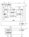
- a tire-side device that includes a vehicle speed estimation unit, a signal processing unit that generates wear data that indicates the wear state of the tire that appears in the waveform of the detection signal, and a first data communication unit that transmits the wear data; And a vehicle side system that includes a second data communication unit that receives wear data, and a control unit that includes a wear determination unit that determines a tire wear state based on the wear data.
- the signal processing unit a state detection unit that detects whether the road surface state is a wet road surface or other than the wet road surface, and a portion corresponding to the arrangement location of the tire side device of the tire as a device placement location,
- a level acquisition unit and a device that acquires the peak level value that is the peak vibration level when the device is placed on the road surface at the moment of stepping on the road surface
- a level calculation unit that calculates the level value of the vibration level in the area after kicking after the placement position is separated from the road surface, and at least one of the peak level value at the time of depression and the level value in the area after kicking. Is generated as wear data.
- the state detection unit detects whether it is on a wet road surface or on other road surface conditions, and when it is a wet road surface, the peak level value of the vibration level at the time of stepping on The level value of the vibration level, for example, at least one of the integrated values is used as wear data. Then, the tire wear state is detected based on the wear data. This makes it possible to detect the tire wear state on a wet road surface.
- FIG. 3 is a block diagram showing detailed configurations of a tire side device and a vehicle body side system. It is a cross-sectional schematic diagram of the tire in which the tire side apparatus was attached. It is an output voltage waveform diagram of a vibration sensor part at the time of tire rotation. It is a figure showing a vibration model of a tire. It is a figure of a general vibration model. It is a figure which shows the result when examining the frequency characteristic of the vibration level of a tire about each of a new tire and a worn tire.
- FIG. 3 is a block diagram showing detailed configurations of a tire side device and a vehicle body side system. It is a cross-sectional schematic diagram of the tire in which the tire side apparatus was attached. It is an output voltage waveform diagram of a vibration sensor part at the time of tire rotation. It is a figure showing a vibration model of a tire. It is a figure of a general vibration model. It is a figure which shows the result when examining the frequency characteristic of the vibration level of a tire about
- FIG. 6 is a comparative diagram showing output voltage waveforms of a vibration sensor unit during rotation of a tire of a new tire and a tire after abrasion. It is a figure showing the frequency characteristic of a vibration spectrum when a groove depth of a tire changes by abrasion. It is a figure which shows the result of having investigated the relationship between the groove depth and the integrated value of the vibration level of a specific frequency band, changing the kind of tire. It is a figure showing change of a detection signal of a vibration sensor part before and after wear of a tire on a wet road surface. It is the figure which showed the block structure of the tire wear detection apparatus concerning 2nd Embodiment. It is the figure which showed the block structure of the tire wear detection apparatus concerning 3rd Embodiment. It is the figure which showed the block configuration of the tire wear detection apparatus concerning 4th Embodiment.
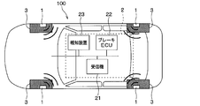
- a tire system 100 having a function of detecting a tire wear state according to the present embodiment will be described with reference to FIGS. 1 to 10.
- the tire system 100 includes a tire side device 1 and a vehicle body side system 2. Then, the tire system 100 transmits information about tire wear from the tire side device 1 to the vehicle body side system 2, and the vehicle body side system 2 determines the tire wear state and informs the user.
- the tire system 100 that can detect the tire wear state in addition to the wet road surface even in a road surface state other than the wet road surface will be described, but any tire system that can detect the tire wear state in at least the wet road surface may be used.
- the tire system 100 is configured to include a tire side device 1 provided on the wheel side and a vehicle body side system 2 including each part provided on the vehicle body side.
- the vehicle-body-side system 2 includes a receiver 21, an electronic control unit (hereinafter, referred to as a brake ECU) 22 for brake control, an informing device 23, and the like.
- a portion of the tire system 100 that realizes a tire wear state detection function corresponds to a tire wear detection device.
- the tire side device 1 and the receiver 21 of the vehicle body side system 2 constitute a tire wear detection device.
- the details of each part which comprises the tire side apparatus 1 and the vehicle body side system 2 are demonstrated.
- the tire side device 1 is configured to include a vibration sensor unit 11, a vehicle speed estimation unit 12, a control unit 13, and a data communication unit 14.
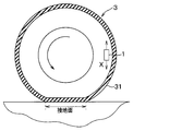
- a vibration sensor unit 11 For example, as shown in FIG. It is provided on the back side of the tread 31.
- the vibration sensor unit 11 constitutes a vibration detection unit for detecting the vibration applied to the tire 3.
- the vibration sensor unit 11 is composed of an acceleration sensor.
- the vibration sensor unit 11 measures, for example, the magnitude of vibration in the tangential direction to the circular trajectory drawn by the tire side device 1 when the tire 3 rotates, that is, in the tire tangential direction indicated by the arrow X in FIG.
- the detection signal of acceleration is output as the detection signal according to. More specifically, the vibration sensor unit 11 generates, as a detection signal, an output voltage in which one of the two directions indicated by the arrow X is positive and the opposite direction is negative.
- the vibration sensor unit 11 detects acceleration every predetermined sampling cycle set to a cycle shorter than one rotation of the tire 3 and outputs it as a detection signal.
- the detection signal of the vibration sensor unit 11 is expressed as an output voltage or an output current, but here, the case of being expressed as an output voltage will be taken as an example.
- the vehicle speed estimation unit 12 estimates the speed of the vehicle to which the tire 3 equipped with the tire side device 1 is attached (hereinafter simply referred to as vehicle speed).
- vehicle speed estimation unit 12 estimates the vehicle speed based on the detection signal of the vibration sensor unit 11.
- the output voltage waveform of the detection signal of the vibration sensor unit 11 during tire rotation is, for example, the waveform shown in FIG.
- a portion of the tread 31 corresponding to the location of the tire-side device 1 (hereinafter referred to as a device location) starts to touch the ground.
- the output voltage of 11 has a maximum value.
- the peak value at the start of grounding when the output voltage of the vibration sensor unit 11 has a maximum value is referred to as a first peak value.
- the output voltage of the vibration sensor unit 11 has a minimum value at the end of grounding when the portion corresponding to the device arrangement location is grounded from the state where it is grounded. ..
- the peak value at the end of grounding when the output voltage of the vibration sensor unit 11 has a minimum value is referred to as a second peak value.
- the reason why the output voltage of the vibration sensor unit 11 takes the peak value at the above timing is as follows. That is, when the device placement location comes into contact with the rotation of the tire 3, the portion of the tire 3 that has been a substantially cylindrical surface until then is pressed in the vicinity of the vibration sensor portion 11 and deformed into a planar shape. By receiving the impact at this time, the output voltage of the vibration sensor unit 11 takes the first peak value. Further, when the location of the device is separated from the ground contact surface as the tire 3 rotates, the pressure on the tire 3 is released in the vicinity of the vibration sensor unit 11 and the tire 3 returns from the planar shape to the substantially cylindrical shape. By receiving an impact when the shape of the tire 3 returns to its original shape, the output voltage of the vibration sensor unit 11 has the second peak value.
- the output voltage of the vibration sensor unit 11 takes the first and second peak values at the start of grounding and at the end of grounding, respectively. Further, since the direction of impact when the tire 3 is pressed is opposite to the direction of impact when released from the pressure, the sign of the output voltage is also opposite.
- the moment when the location of the device on the tire tread 31 comes into contact with the road surface is referred to as the “stepping-in area”, and the moment when the device is separated from the road surface is referred to as the “kicking-out area”.
- the “stepping-in area” includes the timing of reaching the first peak value
- the “kicking-out area” includes the timing of reaching the second peak value.
- the area before the step-in area is the "pre-step-out area”
- the area from the step-in area to the kick-out area, that is, the area where the device is placed on the ground is the "pre-kick-out area”
- the area after the kick-out area is the "post-kick-out area”.
- the period in which the device arrangement location is grounded and before and after it can be divided into five regions.
- the five areas R1 to R5 of the detection signal are the "pre-step area”, the “step area”, the "pre-start area”, the “start area”, and the "post-start area”. Is shown as.
- the detection signal of the vibration sensor unit 11 exhibits the vibration waveform shown in FIG. Therefore, for example, the time interval between the first peak values or between the second peak values is the time required for the tire 3 to make one rotation. Therefore, the vehicle speed estimation unit 12 estimates the vehicle speed from the time taken for the tire 3 to make one rotation and the length of one round of the tire 3.
- the control unit 13 is a portion corresponding to a signal processing unit that creates data regarding a detection target, is configured by a known microcomputer including a CPU, a ROM, a RAM, an I/O, and the like, and is a program stored in the ROM or the like. Various processing is performed according to. For example, the control unit 13 uses the detection signal of the vibration sensor unit 11 as a detection signal representing vibration data in the tire tangential direction, and processes this signal to obtain data regarding the tire wear state (hereinafter referred to as wear data). Then, the process of transmitting it to the data communication unit 14 is performed.
- the control unit 13 determines whether the road surface is a wet road surface or a road surface state other than the wet road surface by detecting the road surface state, for example, a dry road surface, and performs different signal processing to obtain wear data. Creating. Specifically, the control unit 13 obtains the vibration level of the tire 3 by performing waveform processing of the vibration waveform indicated by the detection signal of the vibration sensor unit 11. Then, in the case of a wet road surface, the control unit 13 obtains the peak level value of the vibration level at the time of stepping on or the integral value of the vibration level in the region after kicking.
- the control unit 13 calculates the level value of the vibration level in the predetermined frequency band of the detection signal of the vibration sensor unit 11.
- the level value in this case may be a level value of an arbitrary frequency, but here, the control unit 13 is configured to obtain an integrated value of the level values in a predetermined frequency band.
- the control unit 13 serves as a functional unit for acquiring vibration data, the waveform capturing unit 13a, the state detecting unit 13b, the method determining unit 13c, the filter unit 13d, the integral calculating unit 13e, the peak specifying unit 13f, It has a level acquisition unit 13g and a region specifying unit 13h.
- the waveform capturing unit 13a is a unit for capturing the detection signal of the vibration sensor unit 11.
- the waveform capturing section 13a sets the one rotation of the tire 3 as a capture range, and captures the waveform of one rotation of the tire 3 from the detection signal of the vibration sensor section 11.
- the waveform capturing unit 13a calculates the time required for the tire 3 to make one rotation based on the vehicle speed detection result obtained by the vehicle speed estimating unit 12, and the vibration sensor unit 11 detects the time. I am trying to capture signals.
- the condition detection unit 13b is a part that detects the road surface condition.
- the vibration waveform of the tire 3 indicated by the detection signal of the vibration sensor unit 11 captured by the waveform capturing unit 13a corresponds to the road surface condition. Therefore, by extracting the characteristic of the vibration waveform, it is detected whether it is a wet road surface or a road surface condition other than that. For example, on a wet road surface, the vibration before stepping in becomes large. Therefore, the state detection unit 13b compares the vibration level value indicating the magnitude of the vibration before stepping on, or the average value or integrated value thereof with a predetermined threshold value. If the vibration level value is greater than the threshold value, the wet road surface is used. To determine.
- the method determination unit 13c is a unit that determines a signal processing method according to the road surface condition. As described above, the condition detection unit 13b detects the wet road surface and other road surface conditions. Therefore, the method determination unit 13c selects the normal signal processing method when the road surface state is other than the wet road surface, and selects the signal processing method for the wet road surface when the road surface state is the wet road surface. When the normal signal processing method is selected, the signal processing is performed using the filter unit 13d and the integral calculation unit 13e. When the signal processing method for the wet road surface is selected, signal processing is performed using the peak specifying unit 13f, the level acquiring unit 13g, the area specifying unit 13h, and the integration calculation unit 13e.
- the filter unit 13d extracts a vibration component in a specific frequency band by filtering a predetermined frequency band from the detection signal of the vibration sensor unit 11 for one rotation of the tire 3 captured by the waveform capturing unit 13a.
- the filter unit 13d is configured by a high-pass filter, and a frequency band of, for example, 1.5 kHz or more is extracted from the detection signal of the vibration sensor unit 11 by passing through the filter unit 13d.
- the frequency characteristic of the vibration level in the stepping area and the kicking area of the tire 3 is determined based on the vibration characteristic of the tire 3 including the rubber block, and the vibration level has a peak at the natural vibration frequency of the tire 3 including the rubber block. Then, in a frequency range higher than the natural vibration frequency, the vibration level is attenuated by the vibration isolation effect of the rubber block.
- the natural vibration frequency of the tire 3 including the rubber block changes according to the wear state of the rubber block, and increases as the wear of the rubber block progresses.
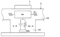
- FIG. 5 shows a vibration model of the tire 3.
- the mass of the portion that affects the vibration applied to the tire side device 1 is Mt
- the spring constant is Kt
- the mass of the rubber block 33 is Mb
- the spring constant is Kb
- the damper damping coefficient is Is described as C.
- the rubber block 33 serves as a low-pass filter when the rubber block 33 serves as a vibration isolator against the input vibration from the road surface.
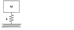
- a general vibration model is expressed as shown in FIG. 6, and the natural vibration frequency Fn in this vibration model is expressed by the following equation.
- k is the spring constant of the vibration isolator in the vibration model
- m is the mass of the vibration source.
- the spring constant k is the thickness of the vibration target, in other words, the height, which is obtained by multiplying the area of the vibration target by the Young's modulus determined by the vibration target constituting the vibration model, that is, the material of the rubber block 33 in this embodiment. It is defined as the divided value.
- the mass Mt is sufficiently larger than the mass Mb
- the spring constant Kt is sufficiently larger than the spring constant Kb. Therefore, substantially considering only the mass Mt and the spring constant Kb, it can be regarded as the general vibration model shown in FIG. That is, the mass m and the spring constant k in the mathematical formula 1 can be replaced with the mass Mt and the spring constant Kb in FIG. 5, respectively.
- the rubber block 33 wears and the height becomes low
- the mass Mb becomes small and the spring constant Kb becomes large accordingly.
- the natural vibration frequency Fn shown in Formula 1 increases.
- the frequency characteristic of the vibration level in the stepping area and the kicking area of the tire 3 is determined based on the vibration characteristic of the tire 3 including the rubber block 33, and at the natural vibration frequency Fn of the tire 3 including the rubber block 33.
- the vibration level reaches a peak.
- the natural vibration frequency Fn increases as the rubber block 33 wears and the height decreases. For example, as shown in FIG. 7, when the tire 3 is new and the groove depth is 8 mm, the natural vibration frequency Fn is 1.0 kHz, and when the tire 3 is worn and the groove depth is 1.6 mm, the natural vibration frequency Fn. Fn became 1.5 kHz.
- the natural vibration frequency Fn has different values depending on the material of the tire 3 and the like, but the natural vibration frequency Fn increases as the tire 3 wears regardless of the material of the tire 3.
- a groove depth that serves as a replacement guideline for the tire 3 is determined, the natural vibration frequency Fn when the groove depth of the tire 3 serves as a replacement guideline is set as a specific frequency, and a frequency band higher than that is set as a specific frequency band. , And can be extracted by the filter unit 13d.
- the filter unit 13d For example, when the recommended groove depth for replacement of the tire 3 is set to 3.0 mm and the depth is set as the groove depth that serves as a guide for replacement of the tire 3, a high frequency of, for example, 1.5 kHz or more in the filter portion 13d. It suffices to extract the band component.
- the integral calculation unit 13e generates wear data corresponding to the vibration level for a specific portion of the vibration waveform of the detection signal input from the filter unit 13d or the region specifying unit 13h, and corresponds to the level calculation unit. In the case of the present embodiment, the integral calculator 13e calculates the integrated value of the vibration level values and uses the integrated value as wear data.
- the integral calculator 13e calculates the integral value of the vibration level values in the specific frequency band extracted by the filter 13d.
- the integral calculation unit 13e calculates the integrated value of the level values of the vibration levels in the after-kick region specified by the region specifying unit 13h, as described later. Calculate The level value here may be calculated from the detection signal for one rotation of the tire 3, or may be calculated as the integrated value of the detection signals for a plurality of rotations of the tire 3, and the integrated value may be calculated. It may be calculated as an average value divided by the number of rotations of the tire 3.
- the natural vibration frequency Fn increases as the tire 3 wears.
- the vibration level of the detection signal of the vibration sensor unit 11 increases as the wear of the tire 3 increases. Therefore, the level value of the vibration level in the specific frequency band varies depending on the wear state of the tire 3, and the integrated value also varies.
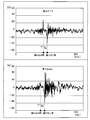
- FIG. 8 shows detection signals of the vibration sensor unit 11 when the tire 3 is new and has a groove depth of 8 mm, and when the wear progresses and the groove depth becomes 1.6 mm.
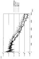
- FIG. 9 shows frequency characteristics of the vibration spectrum when the groove depth of the tire 3 is 8 mm, 3 mm, and 1.6 mm, and in the case of the present embodiment, the acceleration spectrum.
- FIG. 9 shows the frequency characteristics of the vibration spectrum of the tire 3 for one rotation, but the vibration spectrum for one rotation is obtained by acquiring the vibration spectrum of the tire 3 for 10 rotations and obtaining the average value thereof. There is.
- the vibration of the detection signal of the vibration sensor unit 11 is small, but the tire 3 wears and the groove depth increases.
- the vibration spectrum of the detection signal of the vibration sensor unit 11 also becomes larger as the wear state of the tire 3 advances in the frequency band of the natural vibration frequency Fn or higher. I understand. From this, it is understood that the wear state of the tire 3 can be detected by examining the level value of the vibration level in the specific frequency band equal to or higher than the natural vibration frequency Fn, for example, the integrated value thereof.
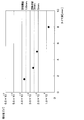
- FIG. 10 is a diagram showing the result, in which the integrated value of the vibration level of the detection signal of the vibration sensor unit 11 is calculated in the frequency band of 1.5 Hz or higher. The integrated value is calculated for 10 revolutions of the tire 3, and the median of the integrated values obtained for each frequency is plotted.
- the wear state of the tire 3 can be detected by examining the level value of the vibration level in the specific frequency band equal to or higher than the natural vibration frequency Fn, for example, the integrated value thereof. Then, for example, if it is determined that the groove depth of the tire 3 becomes 5 mm if the threshold value is set to 0.02 [V], the tire 3 is set if the threshold value is set to 0.025 [V]. When it is determined that the groove depth of 3 is 3 mm, the notification device 23 can notify.
- a warning threshold value is set in addition to the threshold value that serves as a guide for replacing the tire 3, for example, if the warning threshold value is set to 0.035 [V], it is determined that the groove depth of the tire 3 has become 1.6 mm.
- the notification device 23 can warn that the tire 3 needs to be replaced immediately.
- the relationship between the groove depth and the integrated value of the vibration level in the specific frequency band is shown for one type of tire 3, but when a plurality of types of tires 3 were examined, there was a deviation in the integrated value. Even if the type of tire 3 was changed, the relationship was the same.
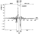
- the peak identifying unit 13f identifies the peak of the vibration level at the time of depression from the vibration waveform of the detection signal for one rotation of the tire 3 captured by the waveform capturing unit 13a. As shown in FIG. 11, how the detection signal of the vibration sensor unit 11 changes before and after the wear of the tire 3 on a wet road surface was examined. It was confirmed that there was a difference in the magnitude of the vibration level in the area.
- the peak identifying unit 13f identifies the timing of the peak in order to obtain the peak value of the vibration level at the time of depression. For example, the detection signal of the vibration sensor unit 11 has the vibration waveform shown in FIG. Therefore, as shown in FIG.
- the peak identifying unit 13f uses the timing at which the vibration level becomes the minimum value at the time of kicking as a reference, and the timing at which the vibration level reaches the maximum value during a period Ta back a predetermined time. was set as the timing at which the vibration level peaks when stepping on.
- the level acquisition unit 13g acquires the peak level value which is the level value at the timing when the peak of the vibration level at the time of depression specified by the peak specification unit 13f is reached.
- the peak level value is acquired by reading the level value at the timing at which the peak of the vibration level at the time of stepping on is specified by the peak specifying unit 13f.
- the area specifying unit 13h specifies the kicked-out area from the vibration waveform of the detection signal for one rotation of the tire 3 captured by the waveform capturing unit 13a. As described above, on the wet road surface, it was confirmed that there is a difference in the magnitude of the vibration level in the region after kicking before and after the wear of the tire 3.
- the area specifying unit 13h specifies the after-kick area in order to obtain the vibration level of the detection signal of the vibration sensor unit 11 in the after-kick area.
- the integration calculating unit 13e causes the level of the vibration level for the area after kicking out of the detection signal of the vibration sensor unit 11.
- the integrated value is calculated and used as wear data.
- control unit 13 controls the acquisition timing of wear data and the data transmission from the data communication unit 14. Specifically, the control unit 13 causes various functional units provided in the control unit 13 to function at a timing at which the wear state of the tire 3 is detected, and wear data corresponding to the vibration level of the detection signal of the vibration sensor unit 11 is acquired. Is transmitted to the data communication unit 14. At this time, the control unit 13 also includes the data regarding the processing method in the wear data so that it can be known whether the wear data is processed by the signal processing method for the wet road surface or the normal signal processing method.
- the control unit 13 calculates the traveling distance of the vehicle from the rotation speed of the tire 3 and detects the wear state of the tire 3 every time the vehicle travels 1 to several hundred km.
- the wear state of the tire 3 may be detected at each timing when it is detected that the vehicle has traveled based on the detection signal of the vibration sensor unit 11, or the control unit 13 may include a timer.
- the wear state of the tire 3 may be detected every predetermined period.
- the data communication unit 14 is a part corresponding to the first data communication unit that communicates with the vehicle body side system 2. For example, when the wear data is transmitted from the control unit 13, the data communication unit 14 performs data transmission at that timing. The timing of data transmission from the data communication unit 14 is controlled by the control unit 13. For example, in the case of wear data, data is transmitted from the data communication unit 14 every time the vehicle travels a predetermined distance from the control unit 13 and wear data is sent.
- the tire-side device 1 is equipped with a power supply unit (not shown) composed of a button battery or the like, and each unit is operated based on the power supply from the power supply unit.
- the power supply unit is configured by a battery such as a button battery.
- the vehicle body side system 2 As described above, the vehicle body side system 2 is provided with the receiver 21, the brake ECU 22, the notification device 23, and the like.
- the receiver 21 receives the wear data transmitted from the tire side device 1 and detects the wear state of the tire 3. Specifically, the receiver 21 is configured to have a data communication unit 21a and a control unit 21b.
- the data communication unit 21a is a part that constitutes the second data communication unit, and plays a role of receiving the wear data transmitted from the data communication unit 14 of the tire side device 1 and transmitting it to the control unit 21b.
- the control unit 21b is composed of a well-known microcomputer including a CPU, a ROM, a RAM, an I/O, etc., and performs various processes according to a program stored in the ROM or the like.
- the control unit 21b is provided with a wear determination unit 21ba, and the wear determination unit 21ba detects tire wear by performing various processes related to the determination of the tire wear state based on the wear data.
- different wear data is used for a wet road surface and a road surface condition that is not a wet road surface such as a dry road surface. Therefore, the wear determination unit 21ba determines whether the road surface state is not a wet road surface or the wet road surface based on the data regarding the processing method of the signal processing included in the wear data. Detects the corresponding tire wear state.
- the wear determination unit 21ba determines the tire wear state based on the integrated value. Making a decision. For example, the wear determination unit 21ba determines the tire wear state by comparing the integrated value with a threshold value obtained by experiments or the like.
- the threshold value may be an integral value corresponding to the groove depth that serves as a guide for replacing the tire 3. That is, when the wear of the tire 3 progresses and the groove depth of the tire 3 reaches the groove depth that is a reference for replacement, it is assumed that the integral calculation unit 13e calculates the groove depth based on the detection signal of the vibration sensor unit 11.
- the integrated value is set as the threshold value. Therefore, the wear determination unit 21ba is in a tire wear state in which it is assumed that the groove depth of the tire 3 has reached the groove depth that is a reference for replacing the tire 3 when the integrated value indicated by the wear data exceeds the threshold value. Detect that.
- the wear determining unit 21ba indicates that the wear state of the tire 3, that is, the tire 3 in accordance with the magnitude of the integral value. It is also possible to determine the groove depth.
- the wear determination unit 21ba uses the wear data as the integrated value of the peak level value of the vibration level at the time of stepping on and the level value of the vibration level in the area after kicking.
- the tire wear state is detected based on the.
- the wear determination unit 21ba determines the tire wear state by comparing the integrated value and the peak level value with a threshold value obtained by an experiment or the like.
- the threshold value may be an integral value or a peak level value corresponding to the groove depth that serves as a guide for replacing the tire 3.
- the integral calculation unit 13e calculates the groove depth based on the detection signal of the vibration sensor unit 11.
- the integrated value and the peak level value acquired by the level acquisition unit 13g are set to the respective threshold values. Therefore, it is assumed that the wear determination unit 21ba has determined that the groove depth of the tire 3 has reached the groove depth that is a reference for replacement of the tire 3 when both the integrated value and the peak level value indicated by the wear data exceed the respective threshold values. It detects that the tire is worn.
- the wear determining unit 21ba indicates that the tire 3 is worn according to the magnitude of the integral value.
- the state, in other words, the groove depth of the tire 3 can also be determined.
- the tire wear state was detected using both the peak level value of the vibration level at the time of stepping on and the integrated value of the level value of the vibration level in the area after kicking, but data indicating at least one of It can be used as wear data to detect the tire wear state.
- the wear determination unit 21ba determines the tire wear state based on the integrated value, but not limited to the integrated value, using the level value of the vibration level of the tire 3 in the specific frequency band, for example, an arbitrary value. The tire wear state can be determined based on the frequency level value.
- the wear determination unit 21ba also notifies the notification device 23 of the detection result of the tire wear state, and the notification device 23 notifies the driver of the tire wear state, if necessary.
- the driver is conscious of driving in accordance with the tire wear state until the tire 3 is replaced, it is possible to avoid the danger of the vehicle, and the worn tire 3 is replaced appropriately. It becomes possible.
- the wear determination unit 21ba transmits the tire wear state to the ECU for executing the vehicle motion control such as the brake ECU 22, and the vehicle motion control is executed based on the transmitted tire wear state. There is.
- the brake ECU 22 constitutes a braking control device that performs various brake controls.
- the brake ECU 22 automatically generates a brake fluid pressure by driving an actuator for controlling the brake fluid pressure, and pressurizes a wheel cylinder to apply a braking force. Generate. Further, the brake ECU 22 can also independently control the braking force of each wheel.
- the brake ECU 22 is notified of the tire wear state determination result from the wear determination unit 21ba. Based on this, the brake ECU 22 performs brake control according to the tire wear state. Specifically, as the vehicle motion control, the brake control is executed on the assumption that the brake becomes less effective as the tire 3 wears more. For example, in the case of brake control in automatic driving or the like, control is performed such that the timing of applying the brake is advanced as the wear state of the tire 3 advances. Further, as the wear of the tire 3 progresses easily, the tire 3 may slip when the braking force increases. Therefore, the control for generating the braking force lower than that before the wear is performed earlier. Execute control.
- the notification device 23 is composed of, for example, a meter display and the like, and is used to notify the driver that the tire is in a worn state that requires careful driving.
- the notification device 23 is configured by a meter display, it is arranged in a place where the driver can visually recognize it while driving the vehicle, and is installed, for example, in an instrument panel of the vehicle.
- the meter display provides a display in a manner that the content can be grasped, thereby visually notifying the driver.
- the notification device 23 may be configured by a buzzer, a voice guidance device, or the like.
- the tire system 100 is configured as described above. It should be noted that the respective units configuring the vehicle body side system 2 are connected to each other via an in-vehicle LAN (abbreviation of Local Area Network) by CAN (abbreviation of Controller Area Network) communication or the like. Therefore, each unit can communicate information with each other through the in-vehicle LAN.
- in-vehicle LAN abbreviation of Local Area Network
- CAN abbreviation of Controller Area Network
- the signal processing method is changed depending on the wet road surface and the other road surface conditions. Then, on a wet road surface, the peak level value of the vibration level at the time of stepping on and the level value of the vibration level in the area after kicking, where the integrated value is used as wear data, the tire wear state is detected based on them. It is carried out. This makes it possible to detect the tire wear state on a wet road surface.
- the wet road surface and the road surface other than the wet road surface may have different portions used for detecting the tire wear state among the detection signals of the vibration sensor unit 11, and the tire wear state may be detected by using the respective suitable portions. ing. Therefore, it is possible to accurately detect the tire wear state on both the wet road surface and the other road surfaces.
- the tire wear state can be detected on both the wet road surface and other road surfaces, but at least on the wet road surface.
- various functional units used for detecting the tire wear state on the wet road surface may be made to function.
- the second embodiment will be described.
- the present embodiment is to make it possible to detect the tire wear state with higher accuracy than the first embodiment, and is otherwise the same as the first embodiment, so only parts different from the first embodiment will be described. explain.
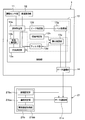
- the control unit 21b of the receiver 21 includes a vehicle information acquisition unit 21bb.
- the vehicle information acquisition unit 21bb acquires information (hereinafter referred to as vehicle information) related to traveling of the vehicle.
- vehicle information information related to traveling of the vehicle.
- the detection signal of the vibration sensor unit 11 is not affected by the running state of the vehicle as much as possible.
- the vehicle information is acquired by the vehicle information acquisition unit 21bb, and wear is sent so that the case where the vehicle is in a traveling state that affects the detection signal of the vibration sensor unit 11 is excluded. From the data, select data that is effective for detecting the tire wear state. As a result, the tire wear state can be detected more accurately.
- the vehicle information includes, for example, vehicle speed information, acceleration/deceleration information, steering information, road surface information, tire pressure information, load information, weather information, position information, temperature information, and the like.
- vehicle information obtaining part 21bb it is preferable to be able to obtain a plurality of pieces.
- the vehicle speed information is handled by, for example, an electronic control unit (hereinafter referred to as ECU) for meter control, so that it can be transmitted from the meter ECU to the vehicle information acquisition unit 21bb via an in-vehicle LAN or the like.
- ECU electronice control unit
- the acceleration/deceleration information is handled by the engine ECU or the like, it can be transmitted from the meter ECU to the vehicle information acquisition unit 21bb through the in-vehicle LAN or the like, and can be acquired by differentiating the vehicle speed indicated by the vehicle speed information with respect to time.
- the steering information is handled by the steering ECU and the like, and thus can be transmitted from the steering ECU to the vehicle information acquisition unit 21bb through the in-vehicle LAN or the like.
- the road surface information is acquired by performing image processing of a road surface image obtained by a vehicle-mounted camera, or by utilizing that the detection signal of the vibration sensor unit 11 also indicates the road surface state, the road surface information obtained from the detection signal is used.
- the data can be transmitted to the tire side device 1 and detected based on this.
- a road surface state detection method for example, a feature amount of tire vibration is acquired from road surface data, and the road surface state is estimated from the degree of similarity between teacher data such as a support vector and the feature amount. Techniques can be applied.
- the tire pressure information can be obtained from, for example, the ECU of the tire pressure monitoring system (hereinafter referred to as TPMS-ECU).
- the tire-side device 1 may be provided with a tire air pressure measurement function, and the tire air pressure may be transmitted to the TPMS-ECU so that the tire air pressure obtained by the TPMS-ECU is transmitted to the vehicle information acquisition unit 21bb.
- the load information since the distance between the first peak value and the second peak value of the vibration waveform of the detection signal of the vibration sensor unit 11 shown in FIG. And the contact length can be calculated.
- the load information can be transmitted to the vehicle information acquisition unit 21bb from there.
- the weather information, location information, and temperature information can be acquired via the navigation ECU, for example.
- the vehicle speed information can be used so that the tire wear state is detected in a preferable vehicle speed range.
- the vibration level of the detection signal of the vibration sensor unit 11 is low when the vehicle speed is low, and is high when the vehicle speed is high. Therefore, it is preferable that the tire wear state be detected when the vehicle speed is not too high and the vibration level is not too low. Therefore, the tire wear state is detected based on the vehicle speed information when the vehicle speed is within a predetermined speed range, for example, 40 km/h ⁇ .
- the acceleration/deceleration information is used to detect that it is not during sudden acceleration or sudden braking. At the time of sudden acceleration or sudden braking, the influence may appear in the detection signal of the vibration sensor unit 11. Therefore, for example, when the acceleration/deceleration is equal to or lower than a predetermined value, the tire wear state is detected.
- ⁇ Steering information is used to detect that the vehicle is traveling straight ahead, for example.
- the influence may appear in the detection signal of the vibration sensor unit 11 while the vehicle is turning. Therefore, for example, the tire wear state is detected when the steering angle is equal to or less than a predetermined value, preferably when the vehicle is traveling straight ahead.
- the tire 3 may slip when traveling on an icy road, and the uneven road surface such as a gravel road may generate vibration due to the unevenness, which may affect the detection signal of the vibration sensor unit 11. Therefore, when the tire wear state is detected on a wet road surface, the tire wear state is detected on a flat road such as an asphalt road surface. When the tire wear state is detected on a road surface other than the wet road surface, the tire wear state is detected while traveling on an asphalt road surface and a dry road surface, for example.
- tire pressure information it is used to detect that it is within the proper pressure range. If the tire air pressure is too high, the tire 3 is easily affected by the unevenness of the road surface, and if the tire air pressure is low, the tire 3 is less likely to vibrate. Therefore, the tire pressure may affect the detection signal of the vibration sensor unit 11. Therefore, the tire wear state is detected when the tire air pressure is within a predetermined proper air pressure range.
- the load information it is used to detect that the load is not too much, specifically when it is not overloaded.
- the vibration characteristics of the tire 3 may change as compared with the normal state. Therefore, the tire wear state is detected when the load is within the predetermined proper load range.
- ⁇ We use weather information to detect environments that are not suitable for detecting tire wear, such as heavy rain, snow, or freezing. During heavy rain, snowfall, freezing, etc., slipping of the tire 3 may occur, and the detection signal of the vibration sensor unit 11 may be affected. Therefore, when the tire wear state is detected on a wet road surface, the tire wear state is detected, for example, during rainfall and when the amount of precipitation is within a predetermined range. Further, when detecting the tire wear state on a road surface other than the wet road surface, for example, when the weather is assumed to be a dry road where the influence of slip is unlikely to occur, the tire wear state is detected. To do.
- the vehicle For location information, it is detected that the vehicle is traveling in a place not suitable for detecting tire wear conditions such as slopes or roads under construction, and is traveling in a place suitable for detecting tire wear conditions such as highways. It is used to detect that It is preferable that the tire wear state be detected when the vehicle is traveling stably at a constant speed. Therefore, the tire wear state should be detected during traveling on a slope or a flat paved road not under construction, preferably a highway.
- the location information can also be used as a combination with weather information. That is, since the weather information is output for each area, if the traveling location of the vehicle is specified from the location information and the weather of the area of the traveling location is acquired from the weather information, the more accurate weather information can be obtained. Thus, the tire wear state can be detected.
- the tire 3 which is a rubber product, becomes soft when the temperature becomes high, and the spring characteristics change, which may lead to a situation that is not suitable for detecting a tire wear state. Therefore, when the outside air temperature is equal to or higher than the predetermined temperature, the tire wear state is not detected.
- the vehicle information acquisition unit 21bb can acquire the vehicle information, and the tire wear state can be detected based on the vehicle information under more suitable conditions. That is, when wear data is sent from the tire side device 1, data effective for detecting the tire wear state is selected from the sent wear data based on the vehicle state acquired by the vehicle information acquisition unit 21bb. be able to. For example, it is possible to select data that is considered to be particularly effective for detecting the tire wear state, such as wear data when the vehicle is traveling straight at a constant speed within a predetermined speed range. This makes it possible to detect the tire wear state with higher accuracy.
- the wear data is transmitted only when the tire side device 1 satisfies the condition. You may do it.
- the waveform capturing unit 13a captures the detection signal of the vibration sensor unit 11 only when the calculated vehicle speed is within the predetermined speed range. To be seen. By doing so, it is possible to transmit the wear data when it is suitable for detecting the tire wear state, and it is possible to more accurately detect the tire wear state and reduce the transmission frequency. It is also possible to reduce power consumption.
- a third embodiment will be described.
- the tire wear state can be initialized with respect to the first and second embodiments, and the other points are the same as those in the first and second embodiments. Only parts different from the second embodiment will be described.
- the configuration of the present embodiment is applied to the first embodiment will be described here as an example, the present invention can also be applied to the second embodiment.
- control unit 21b includes an initial value setting unit 21bc.
- the initial value setting unit 21bc sets the initial value of the tire wear state.
- the relationship between the groove depth of the tire 3 and the integrated value is as shown in FIG. It may be difficult to set a threshold that can be dealt with and an alarm threshold.
- the level value of the vibration level here, the integrated value, a value corresponding to the tire wear state of the tire 3 before wear, that is, a value corresponding to the tire wear state when the tire 3 is new is used as an initial value. It is preferable to perform the standardization based on that.
- the integral value when the tire 3 is new is set to 1, and the normalized integral value is proportional to the variation amount of the integral value for each groove depth, and becomes larger as the variation amount increases. To do. When such standardization was performed, the standardized integral value for each groove depth of the tire 3 became almost the same value regardless of the type of the tire 3.
- the initial value setting unit 21bc sets the integrated value obtained when the tire 3 is new, as the initial value
- the wear determination unit 21ba sets the integrated value obtained when the tire wear state is detected. It is calculated as a normalized integral value expressed as a relative change with respect to the initial value. By doing so, by comparing the normalized integral value with the threshold value or the alarm threshold value, it becomes possible to detect the tire wear state with higher accuracy regardless of the type of the tire 3.
- the method of obtaining the standardized integral value for the groove depth of the tire 3 can be similarly performed for wet road surfaces and other road surfaces. Similar results were obtained when the normalized integral value was calculated in a road surface condition other than the wet road surface by an experiment. Therefore, by standardizing the various road surface states based on the initial values, it becomes possible to detect the tire wear state with higher accuracy regardless of the type of the tire 3.
- a fourth embodiment will be described. This embodiment is different from the first to third embodiments in that the road surface state is detected by the vehicle body side system 2. Others are the same as those in the first to third embodiments. Only parts different from the first to third embodiments will be described. It should be noted that here, the case where the configuration of the present embodiment is applied to the first embodiment will be described as an example, but it is also applicable to the second and third embodiments.
- the state detection unit 21bd is provided for the control unit 21b of the receiver 21, and the state provided in the control unit 13 of the tire side device 1 in the first embodiment and the like.
- the detection unit 13b is omitted.
- the vehicle information acquisition unit 21bb acquires the road surface condition as the vehicle information has been described, but this vehicle information can also be used for detecting the road surface condition in the condition detection unit 21bd. Then, the two-way communication is performed between the tire side device 1 and the vehicle body side system 2, and the data relating to the road surface state detected by the state detection unit 21bd is transmitted as road surface data from the data communication unit 21a to the tire side device 1. To do.
- the tire-side device 1 receives the road surface data through the data communication unit 14 and transmits the road surface data to the method determination unit 13c, and the method determination unit 13c determines the signal processing method based on the road surface data. It will get better.
- the road surface state may be acquired by the vehicle body side system 2 and the road surface data representing the road surface state may be transmitted to the tire side device 1.
- Bluetooth communication including BLE (abbreviation of Bluetooth Low Energy) communication, wireless LAN (abbreviation of Local Area Network) such as wifi, Sub-GHz communication, ultra wide band communication, ZigBee, etc. can be applied as bidirectional communication.
- BLE abbreviation of Bluetooth Low Energy
- wireless LAN abbreviation of Local Area Network
- the vibration sensor unit 11 outputs a detection signal corresponding to the magnitude of vibration in the tangential direction of the tire 3, but this is due to the wear state of the tire 3 on a wet road surface. This is because the change in vibration is the largest in the corresponding direction. However, since the vibration changes in the radial direction and the width direction of the tire 3 depending on the wear state of the tire 3, the vibration sensor unit 11 changes the vibration in the radial direction or the width direction of the tire 3. Alternatively, the tire wear detection may be performed based on the output detection signal.
- the wear state of the tire 3 is detected every 1 to several hundred km of travel. This is also only an example, and the wear state of the tire 3 may be detected for each shorter distance or each longer distance.
- the wear data may be transmitted from the tire side device 1 not only once but a plurality of times.
- the wear data sent from the tire side device 1 when the wear data sent from the tire side device 1 is not selected as valid data, the wear state of the tire 3 is not detected based on the wear data. become. Therefore, it is preferable that the wear data be transmitted from the tire side device 1 a plurality of times so that the wear state of the tire 3 is detected based on any of the wear data. Further, even when the data is transmitted a plurality of times, the wear data may not be selected again as valid data if the running state of the vehicle has not changed. Therefore, it is preferable to set the transmission interval of the wear data to every several hundreds to several kilometers on the assumption that the traveling states are different.
- the case where the detection result of the wear state of the tire 3 is notified from the notification device 23 or is used for the vehicle motion control by being notified to the brake ECU 22 has been described.
- this is also just an example.
- a vehicle communication device capable of communicating with a communication medium outside the vehicle is provided, and notification may be made to a portable device such as a mobile phone or a communication center through the vehicle communication device. it can. If the mobile device is notified, the user can be encouraged to replace the tire 3 through the mobile device. If the communication center is notified, the wear state of the tire 3 can be notified to a vehicle maintenance factory such as a dealer through the communication center. As a result, it becomes possible for the vehicle maintenance factory to notify the user of the replacement of the tire 3 or the like.
- the vehicle speed estimation unit 12 estimates the vehicle speed based on the detection signal of the vibration sensor unit 11 has been described.
- this is also merely an example, and bidirectional communication is enabled by the tire side device 1 and the receiver 21, and the vehicle speed estimation unit is obtained by acquiring the data regarding the vehicle speed from the receiver 21 through the data communication unit 14.
- the vehicle speed may be estimated at 12.
- selecting wear data as in the second embodiment is selection of wear data creation timing. You can That is, based on the vehicle information acquired by the vehicle information acquisition unit 21bb, it is selected that the driving state is effective for detecting the wear state of the tire 3 on the receiver 21 side, and the tire side device 1 is selected at that timing. Outputs a request signal for wear data. Then, in the tire side device 1, when the request signal is received, the wear data is transmitted. In this way, the wear data is delivered to the receiver 21 when the running state is effective for detecting the wear state of the tire 3, so that the wear state of the tire 3 can be accurately determined based on the wear data. It becomes possible to detect.
- the value obtained by dividing the level value of the vibration level in the area after kicking by the peak level value of the vibration level at the time of depression means that the denominator increases and the numerator decreases as tire wear progresses. The change due to tire wear becomes larger. Therefore, it becomes possible to more accurately detect the tire wear state.
- the tire-side device 1 is provided for each of the plurality of tires 3, but at least one may be provided. That is, since the tire wear state is generally the same for a plurality of tires 3, if at least one tire side device 1 is provided, if the tire wear state is detected based on the wear data created there, It can be estimated that the other tires 3 have the same wear state.
Landscapes
- Engineering & Computer Science (AREA)
- Mechanical Engineering (AREA)
- Physics & Mathematics (AREA)
- General Physics & Mathematics (AREA)
- Tires In General (AREA)
Priority Applications (1)
| Application Number | Priority Date | Filing Date | Title |
|---|---|---|---|
| US17/236,539 US11731466B2 (en) | 2018-12-14 | 2021-04-21 | Tire wear detection apparatus having a signal processor in the tire side apparatus including a state detection unit and level acquisition unit and/or level calculaton unit |
Applications Claiming Priority (2)
| Application Number | Priority Date | Filing Date | Title |
|---|---|---|---|
| JP2018-234597 | 2018-12-14 | ||
| JP2018234597A JP7180354B2 (ja) | 2018-12-14 | 2018-12-14 | タイヤ摩耗検知装置 |
Related Child Applications (1)
| Application Number | Title | Priority Date | Filing Date |
|---|---|---|---|
| US17/236,539 Continuation US11731466B2 (en) | 2018-12-14 | 2021-04-21 | Tire wear detection apparatus having a signal processor in the tire side apparatus including a state detection unit and level acquisition unit and/or level calculaton unit |
Publications (1)
| Publication Number | Publication Date |
|---|---|
| WO2020122188A1 true WO2020122188A1 (ja) | 2020-06-18 |
Family
ID=71076428
Family Applications (1)
| Application Number | Title | Priority Date | Filing Date |
|---|---|---|---|
| PCT/JP2019/048737 Ceased WO2020122188A1 (ja) | 2018-12-14 | 2019-12-12 | タイヤ摩耗検知装置 |
Country Status (3)
| Country | Link |
|---|---|
| US (1) | US11731466B2 (enExample) |
| JP (1) | JP7180354B2 (enExample) |
| WO (1) | WO2020122188A1 (enExample) |
Cited By (2)
| Publication number | Priority date | Publication date | Assignee | Title |
|---|---|---|---|---|
| EP4116110A1 (en) * | 2021-07-08 | 2023-01-11 | Volvo Car Corporation | Real-time tire monitoring system |
| JP2024503591A (ja) * | 2021-01-07 | 2024-01-26 | ブリヂストン アメリカズ タイヤ オペレーションズ、 エルエルシー | 音響フットプリント分析を使用してタイヤ摩耗を推定するためのシステム及び方法 |
Families Citing this family (6)
| Publication number | Priority date | Publication date | Assignee | Title |
|---|---|---|---|---|
| JP7367404B2 (ja) * | 2019-09-04 | 2023-10-24 | 株式会社Soken | タイヤ装置 |
| CN112537314A (zh) * | 2019-09-20 | 2021-03-23 | 大陆汽车有限公司 | 用于确定湿路状况的系统和方法 |
| KR102255681B1 (ko) * | 2019-10-02 | 2021-05-27 | 한국타이어앤테크놀로지 주식회사 | 타이어 가속도 신호의 불규칙성을 이용한 타이어 마모 측정 장치 및 이를 이용한 타이어 마모 측정 방법 |
| JP7460379B2 (ja) * | 2020-01-29 | 2024-04-02 | 横浜ゴム株式会社 | 摩耗状態検知装置 |
| CN114161430B (zh) * | 2022-01-07 | 2025-03-18 | 珞石(山东)机器人集团有限公司 | 一种基于非线性摩擦力的机器人运动求解方法 |
| KR20230108932A (ko) * | 2022-01-12 | 2023-07-19 | 주식회사 미래오토스 | 제동 보조 시스템 및 제동 보조 방법 |
Citations (9)
| Publication number | Priority date | Publication date | Assignee | Title |
|---|---|---|---|---|
| US20060156790A1 (en) * | 2003-06-18 | 2006-07-20 | Michelin Recherche Et Technique S.A. | Method for predicting the wear of a tire and system for implementing it |
| JP2007099245A (ja) * | 2005-10-07 | 2007-04-19 | Toyota Motor Corp | 路面状態推定装置および路面状態推定方法 |
| WO2009008502A1 (ja) * | 2007-07-11 | 2009-01-15 | Kabushiki Kaisha Bridgestone | タイヤ摩耗推定方法 |
| WO2009157516A1 (ja) * | 2008-06-25 | 2009-12-30 | 株式会社ブリヂストン | タイヤ摩耗推定方法及びタイヤ摩耗推定装置 |
| JP2010215195A (ja) * | 2009-03-19 | 2010-09-30 | Hitachi Constr Mach Co Ltd | タイヤ磨耗判定装置を備えた車両 |
| US20140366618A1 (en) * | 2013-06-14 | 2014-12-18 | Kanwar Bharat Singh | Tire wear state estimation system and method |
| JP2016190615A (ja) * | 2015-03-31 | 2016-11-10 | 株式会社ブリヂストン | タイヤ摩耗量推定方法及びタイヤ摩耗量推定装置 |
| JP2018167645A (ja) * | 2017-03-29 | 2018-11-01 | 株式会社デンソー | 自動運転制御装置 |
| JP2020027471A (ja) * | 2018-08-13 | 2020-02-20 | Toyo Tire株式会社 | タイヤ保守管理装置およびタイヤ保守システム |
Family Cites Families (1)
| Publication number | Priority date | Publication date | Assignee | Title |
|---|---|---|---|---|
| JP5072463B2 (ja) | 2007-07-11 | 2012-11-14 | 株式会社ブリヂストン | タイヤの摩耗検知方法及びタイヤの摩耗検知装置 |
-
2018
- 2018-12-14 JP JP2018234597A patent/JP7180354B2/ja active Active
-
2019
- 2019-12-12 WO PCT/JP2019/048737 patent/WO2020122188A1/ja not_active Ceased
-
2021
- 2021-04-21 US US17/236,539 patent/US11731466B2/en active Active
Patent Citations (9)
| Publication number | Priority date | Publication date | Assignee | Title |
|---|---|---|---|---|
| US20060156790A1 (en) * | 2003-06-18 | 2006-07-20 | Michelin Recherche Et Technique S.A. | Method for predicting the wear of a tire and system for implementing it |
| JP2007099245A (ja) * | 2005-10-07 | 2007-04-19 | Toyota Motor Corp | 路面状態推定装置および路面状態推定方法 |
| WO2009008502A1 (ja) * | 2007-07-11 | 2009-01-15 | Kabushiki Kaisha Bridgestone | タイヤ摩耗推定方法 |
| WO2009157516A1 (ja) * | 2008-06-25 | 2009-12-30 | 株式会社ブリヂストン | タイヤ摩耗推定方法及びタイヤ摩耗推定装置 |
| JP2010215195A (ja) * | 2009-03-19 | 2010-09-30 | Hitachi Constr Mach Co Ltd | タイヤ磨耗判定装置を備えた車両 |
| US20140366618A1 (en) * | 2013-06-14 | 2014-12-18 | Kanwar Bharat Singh | Tire wear state estimation system and method |
| JP2016190615A (ja) * | 2015-03-31 | 2016-11-10 | 株式会社ブリヂストン | タイヤ摩耗量推定方法及びタイヤ摩耗量推定装置 |
| JP2018167645A (ja) * | 2017-03-29 | 2018-11-01 | 株式会社デンソー | 自動運転制御装置 |
| JP2020027471A (ja) * | 2018-08-13 | 2020-02-20 | Toyo Tire株式会社 | タイヤ保守管理装置およびタイヤ保守システム |
Cited By (4)
| Publication number | Priority date | Publication date | Assignee | Title |
|---|---|---|---|---|
| JP2024503591A (ja) * | 2021-01-07 | 2024-01-26 | ブリヂストン アメリカズ タイヤ オペレーションズ、 エルエルシー | 音響フットプリント分析を使用してタイヤ摩耗を推定するためのシステム及び方法 |
| US20240053231A1 (en) * | 2021-01-07 | 2024-02-15 | Bridgestone Americas Tire Operations, Llc | System and method for estimating tire wear using acoustic footprint analysis |
| JP7551934B2 (ja) | 2021-01-07 | 2024-09-17 | ブリヂストン アメリカズ タイヤ オペレーションズ、 エルエルシー | 音響フットプリント分析を使用してタイヤ摩耗を推定するためのシステム及び方法 |
| EP4116110A1 (en) * | 2021-07-08 | 2023-01-11 | Volvo Car Corporation | Real-time tire monitoring system |
Also Published As
| Publication number | Publication date |
|---|---|
| US11731466B2 (en) | 2023-08-22 |
| JP2020093748A (ja) | 2020-06-18 |
| JP7180354B2 (ja) | 2022-11-30 |
| US20210237517A1 (en) | 2021-08-05 |
Similar Documents
| Publication | Publication Date | Title |
|---|---|---|
| WO2020122188A1 (ja) | タイヤ摩耗検知装置 | |
| JP6777103B2 (ja) | 路面状態判別装置およびそれを含むタイヤシステム | |
| JP6935812B2 (ja) | タイヤ摩耗検知装置 | |
| US11549809B2 (en) | Road surface state determination device and tire system | |
| CN108698593B (zh) | 车辆用危险避免装置 | |
| JP5121452B2 (ja) | 路面状態推定方法、路面状態推定用タイヤ、路面状態推定装置、及び、車両制御装置 | |
| JP5657917B2 (ja) | 路面状態推定方法 | |
| JP6614073B2 (ja) | 路面状態推定装置 | |
| CN111615479B (zh) | 轮胎系统 | |
| JP4817753B2 (ja) | 路面状態推定方法、路面状態推定装置、及び、車両制御装置 | |
| JP5878612B2 (ja) | 路面状態推定方法 | |
| WO2019124482A1 (ja) | 路面状態判別装置 | |
| WO2019142869A1 (ja) | タイヤシステム | |
| WO2019088024A1 (ja) | 路面状態判別装置およびそれを備えたタイヤシステム | |
| WO2019074027A1 (ja) | 路面状態判別装置およびそれを備えたタイヤシステム | |
| JP2018009974A (ja) | タイヤマウントセンサおよびそれを含む路面状態推定装置 | |
| CN111511613A (zh) | 用于发信号通知安装在车辆上的轮胎的滑水状态的方法和系统 | |
| WO2019103095A1 (ja) | 路面状態判別装置 | |
| WO2020054658A1 (ja) | タイヤシステム | |
| WO2019142870A1 (ja) | タイヤシステム | |
| JP7388000B2 (ja) | 路面摩擦係数予測システム | |
| WO2018003693A1 (ja) | タイヤマウントセンサおよびそれを含む路面状態推定装置 | |
| JP2014222252A (ja) | 車両制御方法及び路面状態警告方法 |
Legal Events
| Date | Code | Title | Description |
|---|---|---|---|
| 121 | Ep: the epo has been informed by wipo that ep was designated in this application |
Ref document number: 19897305 Country of ref document: EP Kind code of ref document: A1 |
|
| NENP | Non-entry into the national phase |
Ref country code: DE |
|
| 122 | Ep: pct application non-entry in european phase |
Ref document number: 19897305 Country of ref document: EP Kind code of ref document: A1 |