WO2020121830A1 - Module de piles à combustible, asemblage de piles à combustible et procédé de fabrication de module de piles à combustible - Google Patents
Module de piles à combustible, asemblage de piles à combustible et procédé de fabrication de module de piles à combustible Download PDFInfo
- Publication number
- WO2020121830A1 WO2020121830A1 PCT/JP2019/046603 JP2019046603W WO2020121830A1 WO 2020121830 A1 WO2020121830 A1 WO 2020121830A1 JP 2019046603 W JP2019046603 W JP 2019046603W WO 2020121830 A1 WO2020121830 A1 WO 2020121830A1
- Authority
- WO
- WIPO (PCT)
- Prior art keywords
- gas diffusion
- diffusion layer
- cathode
- anode
- sealing member
- Prior art date
Links
Images


Classifications
-
- H—ELECTRICITY
- H01—ELECTRIC ELEMENTS
- H01M—PROCESSES OR MEANS, e.g. BATTERIES, FOR THE DIRECT CONVERSION OF CHEMICAL ENERGY INTO ELECTRICAL ENERGY
- H01M8/00—Fuel cells; Manufacture thereof
- H01M8/02—Details
- H01M8/0271—Sealing or supporting means around electrodes, matrices or membranes
-
- H—ELECTRICITY
- H01—ELECTRIC ELEMENTS
- H01M—PROCESSES OR MEANS, e.g. BATTERIES, FOR THE DIRECT CONVERSION OF CHEMICAL ENERGY INTO ELECTRICAL ENERGY
- H01M8/00—Fuel cells; Manufacture thereof
- H01M8/02—Details
- H01M8/0271—Sealing or supporting means around electrodes, matrices or membranes
- H01M8/0273—Sealing or supporting means around electrodes, matrices or membranes with sealing or supporting means in the form of a frame
-
- H—ELECTRICITY
- H01—ELECTRIC ELEMENTS
- H01M—PROCESSES OR MEANS, e.g. BATTERIES, FOR THE DIRECT CONVERSION OF CHEMICAL ENERGY INTO ELECTRICAL ENERGY
- H01M8/00—Fuel cells; Manufacture thereof
- H01M8/02—Details
- H01M8/0202—Collectors; Separators, e.g. bipolar separators; Interconnectors
- H01M8/023—Porous and characterised by the material
-
- H—ELECTRICITY
- H01—ELECTRIC ELEMENTS
- H01M—PROCESSES OR MEANS, e.g. BATTERIES, FOR THE DIRECT CONVERSION OF CHEMICAL ENERGY INTO ELECTRICAL ENERGY
- H01M8/00—Fuel cells; Manufacture thereof
- H01M8/02—Details
- H01M8/0202—Collectors; Separators, e.g. bipolar separators; Interconnectors
- H01M8/0247—Collectors; Separators, e.g. bipolar separators; Interconnectors characterised by the form
- H01M8/0254—Collectors; Separators, e.g. bipolar separators; Interconnectors characterised by the form corrugated or undulated
-
- H—ELECTRICITY
- H01—ELECTRIC ELEMENTS
- H01M—PROCESSES OR MEANS, e.g. BATTERIES, FOR THE DIRECT CONVERSION OF CHEMICAL ENERGY INTO ELECTRICAL ENERGY
- H01M8/00—Fuel cells; Manufacture thereof
- H01M8/02—Details
- H01M8/0202—Collectors; Separators, e.g. bipolar separators; Interconnectors
- H01M8/0247—Collectors; Separators, e.g. bipolar separators; Interconnectors characterised by the form
- H01M8/0256—Vias, i.e. connectors passing through the separator material
-
- H—ELECTRICITY
- H01—ELECTRIC ELEMENTS
- H01M—PROCESSES OR MEANS, e.g. BATTERIES, FOR THE DIRECT CONVERSION OF CHEMICAL ENERGY INTO ELECTRICAL ENERGY
- H01M8/00—Fuel cells; Manufacture thereof
- H01M8/10—Fuel cells with solid electrolytes
- H01M8/1004—Fuel cells with solid electrolytes characterised by membrane-electrode assemblies [MEA]
- H01M8/1006—Corrugated, curved or wave-shaped MEA
-
- H—ELECTRICITY
- H01—ELECTRIC ELEMENTS
- H01M—PROCESSES OR MEANS, e.g. BATTERIES, FOR THE DIRECT CONVERSION OF CHEMICAL ENERGY INTO ELECTRICAL ENERGY
- H01M8/00—Fuel cells; Manufacture thereof
- H01M8/10—Fuel cells with solid electrolytes
- H01M2008/1095—Fuel cells with polymeric electrolytes
-
- Y—GENERAL TAGGING OF NEW TECHNOLOGICAL DEVELOPMENTS; GENERAL TAGGING OF CROSS-SECTIONAL TECHNOLOGIES SPANNING OVER SEVERAL SECTIONS OF THE IPC; TECHNICAL SUBJECTS COVERED BY FORMER USPC CROSS-REFERENCE ART COLLECTIONS [XRACs] AND DIGESTS
- Y02—TECHNOLOGIES OR APPLICATIONS FOR MITIGATION OR ADAPTATION AGAINST CLIMATE CHANGE
- Y02E—REDUCTION OF GREENHOUSE GAS [GHG] EMISSIONS, RELATED TO ENERGY GENERATION, TRANSMISSION OR DISTRIBUTION
- Y02E60/00—Enabling technologies; Technologies with a potential or indirect contribution to GHG emissions mitigation
- Y02E60/30—Hydrogen technology
- Y02E60/50—Fuel cells
-
- Y—GENERAL TAGGING OF NEW TECHNOLOGICAL DEVELOPMENTS; GENERAL TAGGING OF CROSS-SECTIONAL TECHNOLOGIES SPANNING OVER SEVERAL SECTIONS OF THE IPC; TECHNICAL SUBJECTS COVERED BY FORMER USPC CROSS-REFERENCE ART COLLECTIONS [XRACs] AND DIGESTS
- Y02—TECHNOLOGIES OR APPLICATIONS FOR MITIGATION OR ADAPTATION AGAINST CLIMATE CHANGE
- Y02P—CLIMATE CHANGE MITIGATION TECHNOLOGIES IN THE PRODUCTION OR PROCESSING OF GOODS
- Y02P70/00—Climate change mitigation technologies in the production process for final industrial or consumer products
- Y02P70/50—Manufacturing or production processes characterised by the final manufactured product
Definitions
- the present disclosure relates to a fuel cell module, a fuel cell stack, and a method for manufacturing the fuel cell module.
- the membrane-electrode assembly is sandwiched by a pair of separators, and each of the membrane-electrode assembly and the pair of separators has a resin portion containing a fiber in at least a part thereof. Are bonded together and joined together.
- the membrane-electrode assembly described in Patent Document 2 has a protective layer formed at the peripheral end of the electrode layer, and has an overlapping portion where the electrode layer and the protective layer overlap in the thickness direction.
- the fuel cell module of the present disclosure is A polymer electrolyte membrane, An anode catalyst layer provided on the first main surface of the polymer electrolyte membrane; A cathode catalyst layer provided on the second main surface of the polymer electrolyte membrane; A pair of gas diffusion layers, one of which is laminated on the anode catalyst layer and the other of which is laminated on the cathode catalyst layer; A membrane-electrode assembly having A pair of separators sandwiching the membrane-electrode assembly, The membrane-electrode assembly, each of the pair of separators, and a sealing member for bonding and sealing, One gas diffusion layer of the pair of gas diffusion layers, and the sealing member, overlapping in the thickness direction in a region including the central edge of the sealing member, Part of a portion of the one gas diffusion layer corresponding to the region is cut out so as to penetrate in the thickness direction.
- the fuel cell stack according to the present disclosure has a plurality of the above fuel cell modules.
- the manufacturing method of the fuel cell module of the present disclosure In at least one gas diffusion layer of the pair of gas diffusion layers, a gas diffusion layer processing step of reducing the volume of at least a part of the outer peripheral portion, An arrangement step of arranging the membrane-electrode assembly including the pair of gas diffusion layers and the sealing member such that the outer peripheral portion overlaps with the sealing member in the thickness direction at least in part. A bonding step of sandwiching the sealing member and the membrane-electrode assembly with a pair of separators, and bonding the membrane-electrode assembly and the pair of separators, including.
- the present disclosure it is possible to provide a fuel cell module and a fuel cell stack in which damage or deterioration of the electrolyte membrane is suppressed, and a method for manufacturing the fuel cell module.
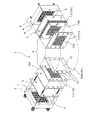
- 1 is an exploded perspective view of a fuel cell stack according to a first embodiment of the present disclosure.
- 1 is a plan view of a membrane-electrode assembly and a sealing member of a fuel cell module according to Embodiment 1 of the present disclosure AA line cross-sectional view of the membrane-electrode assembly of FIG.
- the top view of the anode gas diffusion layer of the fuel cell module concerning Embodiment 1 of this indication.
- the figure which expanded a part of outer peripheral part processed into the sawtooth shape of the gas diffusion layer of FIG. 4 and FIG. The figure which expanded a part of outer peripheral part in which the through-hole of the gas diffusion layer of FIG.
- Sectional drawing which shows the positional relationship of the structural member of the fuel cell module concerning Embodiment 1 of this indication.
- Partial cross-sectional view of a fuel cell module according to Embodiment 1 of the present disclosure Partial cross-sectional view of a fuel cell module according to Embodiment 1 of the present disclosure Exemplary Flowchart of Manufacturing Method of Fuel Cell Module According to First Embodiment of Present Disclosure
- the top view of the cathode gas diffusion layer concerning Embodiment 2 of this indication.
- Partial cross-sectional view of a fuel cell module according to Embodiment 2 of the present disclosure Plan view of an electrolyte membrane-electrode assembly and a sealing member in a fuel cell module according to Embodiment 3 of the present invention 17 is a cross-sectional view taken along the line AA of the electrolyte membrane-electrode assembly of FIG.
- Partial cross-sectional view of a fuel cell module according to Embodiment 3 of the present invention FIG. 3 is a partial cross-sectional view showing the positional relationship of fuel cell module members according to Embodiment 3 of the present invention.
- Plan view of a gas diffusion layer according to Embodiment 3 of the present invention Plan view of the gas diffusion layer with the outer periphery processed into a sawtooth shape Plan view of a gas diffusion layer with a through hole in the outer periphery
- Exemplary Flowchart of Manufacturing Method of Fuel Cell Module According to Embodiment 3 of Present Invention Cross-sectional view of conventional polymer electrolyte fuel cell components Partial cross-sectional view of a conventional fuel cell module
- a polymer electrolyte fuel cell is a device that simultaneously generates electric power and heat by electrochemically reacting a fuel gas containing hydrogen with an oxidant gas containing oxygen such as air.
- the polymer electrolyte fuel cell will be referred to as PEFC (Polymer Electrolyte Fuel Cell).
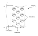
- the basic structure of the PEFC is shown in the sectional view of FIG.
- the PEFC includes an electrolyte membrane 1500 that selectively transports hydrogen ions, and an anode electrode 1900 and a cathode electrode 2000 formed on both surfaces of the electrolyte membrane 1500.
- the anode electrode 1900 has an anode catalyst layer 1600 formed on the first main surface 1510 of the electrolyte membrane 1500 and an anode gas diffusion layer 1810 laminated on the outside of the anode catalyst layer 1600.
- the cathode electrode 2000 has a cathode catalyst layer 1700 formed on the second main surface 1520 of the electrolyte membrane 1500 and a cathode gas diffusion layer 1820 laminated on the outside of the cathode catalyst layer 1700.
- the anode gas diffusion layer 1810 and the cathode gas diffusion layer 1820 have the functions of air permeability and electronic conductivity.
- the membrane-electrode assembly 1000 is an assembly in which the electrolyte membrane 1500 and the electrodes 1900 and 2000 are integrally joined and assembled.
- the membrane-electrode assembly may be referred to as MEA (Membrane Electrode Assembly).
- FIG. 1 A sectional view of the MEA1000 is shown in FIG.
- An anode separator 1110 is provided on the anode electrode 1900 side of the MEA 1000, and a cathode separator 1120 is provided on the cathode electrode 2000 side of the MEA 1000.
- the anode separator 1110 and the cathode separator 1120 mechanically sandwich and fix the MEA 1000.
- the structure in which the MEA 1000 is sandwiched by the pair of separators 1110 and 1120 is the fuel cell module (single cell module) 2100.
- the separators 1110 and 1120 are members for electrically connecting adjacent fuel cell modules 2100 to each other in series.
- a gas passage groove 1310 for supplying a reaction gas to the anode electrode 1900 and carrying away generated water and surplus gas is formed in a portion of the anode separator 1110 that is in contact with the MEA 1000.
- a gas passage groove 1320 is also formed in a portion of the cathode separator 1120 that contacts the MEA 1000.
- manifold holes are provided at the edges of the separators 1110 and 1120 to distribute the reaction gas. Furthermore, the pair of separators 1110 are provided so as to surround the outer periphery of the electrode forming portion of the MEA 1000, that is, the power generation region, so that the reaction gas or the like supplied to the gas flow channel 1310, 1320 does not leak or mix to the outside.
- the sealing member 900 is disposed between 1120.
- a frame is fitted to the outer edge of the MEA 1000 shown in FIG.
- a sealing member 900 gasket is fitted to the outer edge (peripheral portion) of the MEA 1000.
- Conductive separators 1110, 1120 are arranged on both sides of the MEA 1000 in the thickness direction.
- a resin frame body for holding the MEA 1000 and an elastic body seal are used as the sealing member 900 between the separators 1110 and 1120. In this case, it is necessary to fill the gap between the resin frame body and the electrolyte membrane 1500 with an elastic body seal, which requires high dimensional accuracy of parts and assembly accuracy. Therefore, it is difficult to make the elastic seal thin in order to prevent the tolerance from becoming too small, as well as having a complicated seal shape that does not cause a gap within the tolerance range.
- a fuel cell stack in which a plurality of fuel cell modules 2100 are stacked and connected in series to obtain a high voltage is required to be downsized or thinned.
- an elastic seal is used, it is difficult to make it smaller or thinner. Therefore, as in Patent Document 1, a method of realizing a thin module by using an insulating thermosetting resin as the sealing member 900 is known.
- the protective layer (sealing member) has an overlapping portion that overlaps with the electrode layer (gas diffusion layer)
- the protective layer and the electrode layer overlap when a load is applied with the MEA sandwiched by the separators.
- stress is concentrated on the separator and the electrolyte membrane, which may damage the separator or rupture the electrolyte membrane.
- the protective layer with steps to avoid stress concentration, or when designing the dimensions of the electrode layer so that there is no overlap with the protective layer, the electrolyte membrane and electrode layer may be exposed due to alignment and assembly tolerances. May remain.
- the present inventors have conducted diligent studies to prevent stress concentration on the separator and the electrolyte membrane and suppress deterioration of the electrolyte membrane even when the electrode layer and the protective layer have an overlapping portion, I got the knowledge of.
- the present inventors have found a structure in which a void (space) is formed in the outer peripheral portion of the gas diffusion layer. Specifically, at least a part of a portion of the gas diffusion layer that overlaps with the sealing member overlaps the gas diffusion layer and the sealing member in a region including the opening-side edge of the sealing member having the opening. Have found a structure in which a void penetrates in the thickness direction. As a result, it is possible to form a void for the gas diffusion layer to be deformed in the surface direction. Therefore, when a load is applied to the gas diffusion layer in the thickness direction, the gas diffusion layer can be deformed toward the void.
- a polymer electrolyte membrane An anode catalyst layer provided on the first main surface of the polymer electrolyte membrane; A cathode catalyst layer provided on the second main surface of the polymer electrolyte membrane; A pair of gas diffusion layers, one of which is laminated on the anode catalyst layer and the other of which is laminated on the cathode catalyst layer; A membrane-electrode assembly having A pair of separators sandwiching the membrane-electrode assembly, The membrane-electrode assembly, each of the pair of separators, and a sealing member for bonding and sealing, One gas diffusion layer of the pair of gas diffusion layers, and the sealing member, overlapping in the thickness direction in a region including the central edge of the sealing member, Part of a portion of the one gas diffusion layer corresponding to the region is cut out so as to penetrate in the thickness direction, A fuel cell module is provided.
- a fuel cell module may be provided in which a plurality of through holes penetrating in the thickness direction are provided in a portion of the one gas diffusion layer corresponding to the region.
- the first diffusion layer when a load is applied to the first diffusion layer in the thickness direction, the first diffusion layer can be deformed toward the through hole.
- a fuel cell module may be provided in which a sawtooth portion formed in a sawtooth shape in a plan view is provided in a portion of the one gas diffusion layer corresponding to the region.
- the first diffusion layer when a load is applied to the first diffusion layer in the thickness direction, the first diffusion layer can be deformed toward the space between the sawtooth portions.
- the pair of gas diffusion layers are an anode gas diffusion layer laminated on the anode catalyst layer, and a cathode gas diffusion layer laminated on the cathode catalyst layer,
- the pair of separators are disposed on the anode gas diffusion layer side of the membrane-electrode assembly, and on the cathode gas diffusion layer side of the membrane-electrode assembly, and form a pair with the anode separator.
- a cathode separator sandwiching the membrane-electrode assembly comprising:
- the sealing member is An anode sealing member having an opening and bonding and sealing the membrane-electrode assembly and the anode separator,
- a cathode sealing member having an opening and bonding and sealing the membrane-electrode assembly and the cathode separator,
- the anode gas diffusion layer When viewed from a direction perpendicular to the first main surface, has an anode side inner side overlapping the anode sealing member in a region including an edge of the anode sealing member on the opening side.
- the cathode gas diffusion layer has a cathode side inner side that overlaps with the cathode sealing member in a region including an edge of the cathode sealing member on the opening side.
- the anode gas diffusion layer at least a portion including the anode-side inner region, a void is formed penetrating in the thickness direction of the anode gas diffusion layer
- the cathode gas diffusion layer at least a portion including the cathode-side inner region, a void is formed penetrating in the thickness direction of the cathode gas diffusion layer
- a fuel cell module in which the anode-side inner region and the cathode-side inner region do not overlap each other when viewed from a direction perpendicular to the first main surface.
- voids are formed in at least a part of the anode-side inner region and the cathode-side inner region, so that when stress is applied in the thickness direction of the fuel cell module, concentration of stress on the constituent members is prevented. Can be prevented. As a result, damage or deterioration of the polymer electrolyte membrane can be suppressed.
- the anode-side inner region may provide a fuel cell module having an outer portion located outside the cathode-side inner region and an inner portion located inside the cathode-side inner region.
- the anode-side inner region and the cathode-side inner region do not overlap each other, so that stress concentration can be prevented when a load is applied in the thickness direction of the fuel cell module.
- At least one of the void formed in the anode gas diffusion layer and the void formed in the cathode gas diffusion layer may provide a fuel cell module including a plurality of through holes.
- the gas diffusion layer when a load is applied in the thickness direction of the fuel cell module, the gas diffusion layer can be deformed toward the through hole, so that stress concentration can be prevented.
- At least one of the void formed in the anode gas diffusion layer and the void formed in the cathode gas diffusion layer has a sawtooth cutout when viewed from a direction perpendicular to the first main surface.
- a fuel cell module formed by the method may be provided.
- the gas diffusion layer when a load is applied in the thickness direction of the fuel cell module, the gas diffusion layer can be deformed toward the notches between the sawtooth portions, so that stress concentration can be prevented. it can.
- a fuel cell stack may be provided in which a plurality of the fuel cell modules according to any one of the first to seventh aspects are connected in series and stacked.
- a gas diffusion layer processing step of reducing the volume of at least a part of the outer peripheral portion An arrangement step of arranging the membrane-electrode assembly including the pair of gas diffusion layers and the sealing member such that the outer peripheral portion overlaps with the sealing member in the thickness direction at least in part.
- a polymer electrolyte membrane having an anode catalyst layer on the first main surface and a cathode catalyst layer on the second main surface; an anode gas diffusion layer and a cathode gas diffusion layer; an anode separator and a cathode separator; Further comprising a preparation step of preparing an anode sealing member and a cathode sealing member, In the gas diffusion layer processing step, voids are formed in at least a part of outer peripheral portions of the anode gas diffusion layer and the cathode gas diffusion layer, In the disposing step, the anode gas diffusion layer is laminated on the anode catalyst layer side of the polymer electrolyte membrane, and the cathode gas diffusion layer is laminated on the cathode catalyst layer side to form a membrane-electrode assembly, The anode sealing member is arranged so as to overlap at least part of the outer peripheral portion of the anode gas diffusion layer, and the cathode sealing member is
- the bonding step the anode gas diffusion layer of the membrane-electrode assembly and the anode separator are bonded together by the anode sealing member, and the cathode gas diffusion layer of the membrane-electrode assembly and the cathode separator are bonded together.
- a method of manufacturing a fuel cell module may be provided in which the membrane-electrode assembly is adhered by the cathode sealing member and the membrane-electrode assembly is sandwiched by the anode separator and the cathode separator.
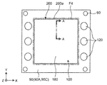
- FIG. 1 is an exploded perspective view of the fuel cell stack according to the first embodiment.
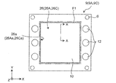
- FIG. 2 is a plan view of the membrane-electrode assembly and the sealing member in the fuel cell module according to this embodiment.
- FIG. 3 is a cross-sectional view of the membrane-electrode assembly of FIG. 2 taken along the line AA.
- the fuel cell stack 1 is, for example, a polymer electrolyte fuel cell (PEFC), which electrochemically reacts a fuel gas containing hydrogen with an oxidant gas containing oxygen such as air. By doing so, electric power, heat, and water are generated at the same time.
- the fuel cell stack 1 includes, for example, a fuel cell module (cell) 2 that is a single cell module, a current collector plate 3, an end plate 4, and a spring 5.
- a fuel cell module (cell) 2 that is a single cell module, a current collector plate 3, an end plate 4, and a spring 5.
- a plurality of fuel cell modules 2 are stacked so as to be connected in series. Note that FIG. 1 shows a state in which one fuel cell module 2 is disassembled and the remaining fuel cell modules 2 are stacked.
- a current collector plate 3, an end plate 4, and a spring 5 are attached to the outermost layers at both ends of the fuel cell stack 1.
- An end plate 4 and a current collector plate 3 arranged inside the end plate 4 are attached to both ends of the fuel cell stack 1, and a plurality of end plates 4 are provided on the inner surface of the end plate 4, that is, on the surface of the fuel cell module 2.
- the spring 5 is arranged.
- the fuel cell stack 1 is fastened with fastening bolts 7 and nuts 8 which are inserted into the bolt holes 6 from both ends.
- the fuel cell module 2 includes a membrane-electrode assembly 10, an anode separator 11A, a cathode separator 11C, an anode sealing member 9A, and a cathode sealing member 9C.
- the membrane-electrode assembly 10 includes an anode catalyst layer 16 provided on the first main surface 15a of the polymer electrolyte membrane 15 and a cathode catalyst layer 17 provided on the second main surface 15b of the polymer electrolyte membrane 15. And an anode gas diffusion layer 18A laminated on the anode catalyst layer 16 and a cathode gas diffusion layer 18C laminated on the cathode catalyst layer 17.
- the anode separator 11A is arranged on the anode gas diffusion layer 18A side of the membrane-electrode assembly 10.
- the cathode separator 11C is arranged on the cathode gas diffusion layer 18C side of the membrane-electrode assembly 10 and forms a pair with the anode separator 11A to sandwich the membrane-electrode assembly 10.
- the anode sealing member 9A has an opening and bonds the membrane-electrode assembly 10 and the anode separator 11A.
- the cathode sealing member 9C has an opening and bonds the membrane-electrode assembly 10 and the cathode separator 11C.
- a cooling water separator 11W may be arranged outside the anode separator 11A and the cathode separator 11C.
- the membrane-electrode assembly may be referred to as MEA.
- the anode sealing member 9A and the cathode sealing member 9C may be collectively referred to as a sealing member 9.
- the anode separator 11A, the cathode separator 11C, and the cooling water separator 11W may be collectively referred to as the separator 11.
- the anode gas diffusion layer 18A and the cathode gas diffusion layer 18C may be collectively referred to as a gas diffusion layer 18.
- the current collector plate 3 is arranged outside the stacked body of the fuel cell module 2.
- the current collector plate 3 may be, for example, a copper plate plated with gold.
- the current collector plate 3 may be made of a metal material having good electric conductivity, such as iron, nickel, stainless steel, or aluminum. Further, surface treatment such as tin plating or nickel plating may be applied.
- the end plate 4 is arranged outside the current collector plate 3.
- the end plate 4 is formed of, for example, an electrically insulating material and also functions as an insulating plate.
- the end plate 4 can be formed by injection molding using, for example, polyphenylene sulfide resin.
- the pipe integrated with the end plate 4 is pressed against, for example, the manifold hole 12 of the stack of the fuel cell module 2 via a gasket (not shown).
- a spring 5 that applies a load to the fuel cell module 2 is arranged on the inner surface of the end plate 4, that is, the surface on the fuel cell module 2 side.
- the springs 5 are centrally arranged in a portion overlapping with the MEA 10 of the fuel cell module 2 when stacked.
- the fuel cell stack 1 is fastened by the fastening bolts 7 and the nuts 8 so that the biasing force of the spring 5 becomes a predetermined value.
- ⁇ Polymer electrolyte membrane> As the polymer electrolyte membrane 15, a solid polymer material having proton conductivity, for example, a perfluorosulfonic acid membrane can be used. As the perfluorosulfonic acid film, for example, a Nafion film manufactured by DuPont can be adopted.
- the MEA 10 is, for example, an anode catalyst layer mainly composed of carbon powder carrying a platinum ruthenium alloy catalyst on the anode-side surface of the polymer electrolyte membrane 15 that selectively transports hydrogen ions, that is, the first main surface 15a. 16 are formed. Further, a cathode catalyst layer 17 whose main component is, for example, carbon powder carrying a platinum catalyst is formed on the cathode-side surface of the polymer electrolyte membrane 15, that is, the second main surface 15b. An anode gas diffusion layer 18A is laminated on the anode catalyst layer 16, and a cathode gas diffusion layer 18C is laminated on the cathode catalyst layer 17.
- the anode gas diffusion layer 18A is laminated on the anode catalyst layer 16 and has the functions of fuel gas permeability and electrical conductivity.
- the cathode gas diffusion layer 18C is laminated on the cathode catalyst layer 17 and has a function of permeable to the oxidizing gas and a function of electrical conductivity.
- the gas diffusion layer 18 for example, carbon paper or carbon cloth is used.
- the anode separator 11A and the cathode separator 11C are formed in a flat plate shape.
- the surfaces of the anode separator 11A and the cathode separator 11C that come into contact with the MEA 10, that is, the inner surface 11Ai and the inner surface 11Ci shown in FIGS. 8 and 9 to be described later have a fuel gas passage groove 13A and an oxidizer depending on the shape of the MEA 10.
- the gas passage groove 13C is formed.
- the inner surface 11Ai of the anode separator 11A is formed so as to contact the gas diffusion layer 18A (FIG. 3) of the MEA 10.
- the inner surface 11Ci of the cathode separator 11C is formed so as to be in contact with the gas diffusion layer 18C (FIG. 3) of the MEA 10.
- Cooling water passage grooves 13W are formed on outer surfaces 11Ao and 11Co of anode separator 11A and cathode separator 11C shown in FIGS. 8 and 9 to be described later, and on both surfaces of cooling water separator 11W.
- the separator 11 is formed of a gas impermeable conductive material.
- the separator 11 for example, one obtained by cutting a resin-impregnated carbon material into a predetermined shape, one obtained by molding a mixture of carbon powder and a resin material, or one obtained by molding a metal can be used.
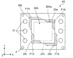
- FIG. 2 is a view of the MEA 10 and the sealing member 9 as seen from a direction perpendicular to the first main surface 15a.
- the direction perpendicular to the first main surface 15a may be referred to as the thickness direction.
- a state viewed from a direction perpendicular to the first main surface 15a may be referred to as a plan view.
- the sealing member 9 is provided with an opening 26.
- the opening 26 is a through hole that penetrates in the central portion of the sealing member 9 in the thickness direction, that is, the Z-axis direction in FIG. 2.
- a fiber sheet encapsulated in an insulating resin is used as the sealing member 9 for example.
- the fiber sheet encapsulated in the resin may be, for example, a prepreg obtained by impregnating glass fiber with an epoxy resin in consideration of insulation, heat resistance, gas permeability, and the like.
- an inorganic fiber such as a ceramic fiber may be used depending on the strength, the thickness, the linear expansion coefficient, the contained substance, and the like.
- the resin may be another thermosetting resin such as a phenol resin, an unsaturated polyester resin, or a polyurethane resin, and a resin containing a fiber and another resin are laminated in multiple layers, or The composition may be partially different.
- the fiber sheet encapsulated in the insulating resin is used, but an adhesive sheet having an adhesive layer formed on both sides of a base material such as a polyethylene naphthalate film may be used.
- a manifold hole 12 and a bolt hole 6 are provided in the peripheral portion of the separator 11 and the sealing member 9 so as to penetrate in the thickness direction.
- the manifold hole 12 is a through hole through which the fuel gas, the oxidant gas, and the cooling water flow.
- the anode sealing member 9A is arranged so as to overlap the anode gas diffusion layer 18A in the thickness direction.
- anode sealing member 9A is arranged so as to overlap anode gas diffusion layer 18A in the thickness direction in a region including edge 26a on the side of opening 26.
- a portion of the anode sealing member 9A overlapping the anode gas diffusion layer 18A is referred to as a region F1.
- the cathode sealing member 9C is arranged so as to overlap the cathode gas diffusion layer 18C in a region including the edge 26a on the opening 26 side.
- the region F1 is a region from the edge 26a of the opening 26 of the sealing member 9 to a position separated by a predetermined length outward in the plane direction in plan view, and the sealing member 9 Indicates a region overlapping with the gas diffusion layer 18. Further, the sealing member 9 is arranged so as to cover the outer peripheral portion of the gas diffusion layer 18.
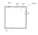
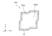
- FIG. 4 is a plan view of the cathode gas diffusion layer 18C.
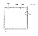
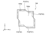
- FIG. 5 is a plan view of the anode gas diffusion layer 18A.
- FIG. 6 is a processing example of the outer peripheral portions of the anode gas diffusion layer 18A and the cathode gas diffusion layer 18C, and is an enlarged view of X1 in FIG. 4 and X2 in FIG.
- FIG. 7 is another example of processing the outer peripheral portions of the anode gas diffusion layer 18A and the cathode gas diffusion layer 18C, and is an enlarged view of X1 in FIG. 4 and X2 in FIG. 4 to 7, some parts are emphasized for the sake of explanation.
- the cathode gas diffusion layer 18C When viewed from a direction perpendicular to the first main surface 15a, the cathode gas diffusion layer 18C is a region including the edge 26Ca of the cathode sealing member 9C on the side of the opening 26C, and the cathode side overlapping the cathode sealing member 9C. It has an inner region F2.
- the cathode side inner region F2 is a portion corresponding to the region F1 in FIG. 2, that is, a portion where the cathode sealing member 9C and the cathode gas diffusion layer 18C overlap. Further, as shown in FIG.
- the cathode gas diffusion layer 18C includes a first cathode gas diffusion layer 18Ce, which is an outer peripheral portion of the cathode gas diffusion layer 18C including the cathode side inner region F2, and a first cathode gas diffusion layer.
- the second cathode gas diffusion layer 18Cd which is the inner portion of 18Ce. That is, the first cathode gas diffusion layer 18Ce is a portion located in the outermost layer in the plane direction of the cathode gas diffusion layer 18C.
- the cathode gas diffusion layer 18C has a cathode-side inner region F2 that is a portion that overlaps with the cathode sealing member 9C in the thickness direction, in at least a part of the outer peripheral portion.
- the first cathode gas diffusion layer 18Ce is a portion including the cathode side inner region F2. That is, the cathode sealing member 9C overlaps in the thickness direction in a part of the first cathode gas diffusion layer 18Ce.
- the anode gas diffusion layer 18A When viewed from the direction perpendicular to the first main surface 15a, the anode gas diffusion layer 18A is a region including the edge 26Aa on the opening 26A side of the anode sealing member 9A, and the anode side overlapping the anode sealing member 9A. It has an inner region F3.
- the anode side inner region F3 is a portion corresponding to the region F1 in FIG. 2, that is, a portion where the anode sealing member 9A and the anode gas diffusion layer 18A overlap. Further, as shown in FIG.
- the anode gas diffusion layer 18A includes a first anode gas diffusion layer 18Ae, which is an outer peripheral portion of the anode gas diffusion layer 18A including the anode-side inner region F3, and a first anode gas diffusion layer.
- the second anode gas diffusion layer 18Ad which is the inner portion of 18Ae. That is, the first anode gas diffusion layer 18Ae is a portion located on the outer peripheral portion of the anode gas diffusion layer 18A.
- the anode gas diffusion layer 18A has an anode-side inner region F3 that is a portion that overlaps with the anode sealing member 9A in the thickness direction, at least in a part of the outer peripheral portion.
- the first anode gas diffusion layer 18Ae is a portion including the anode side inner region F3. That is, the anode sealing member 9A overlaps in the thickness direction in a part of the first anode gas diffusion layer 18Ae.
- a void that penetrates in the thickness direction of the cathode gas diffusion layer 18C is formed in a part including at least the cathode side inner region F2.
- the anode gas diffusion layer 18A has a void that penetrates in the thickness direction of the anode gas diffusion layer 18A in a portion including at least the anode-side inner region F3.
- the voids formed in the anode gas diffusion layer 18A and the cathode gas diffusion layer 18C are, for example, as shown in FIG. 6, voids 22a formed by sawtooth portions 24A and 24C formed in a sawtooth shape in plan view.
- the sawtooth portions 24A and 24C are portions in which a plurality of notches are formed along the end of the gas diffusion layer 18 and a plurality of pointed points are formed.
- the sawtooth portions 24A and 24C are provided on the first anode gas diffusion layer 18Ae of the anode gas diffusion layer 18A or the first cathode gas diffusion layer 18Ce of the cathode gas diffusion layer 18C.
- void 22a is formed between saw tooth portions 24A and 24C.
- the sawtooth portions 24A and 24C may be provided on the entire outer circumferences of the first anode gas diffusion layer 18Ae and the first cathode gas diffusion layer 18Ce.
- the voids formed in the gas diffusion layer 18 are, as shown in FIG. 7, a plurality of through holes 22Ab and 22Cb provided in the first anode gas diffusion layer 18Ae and the first cathode gas diffusion layer 18Ce. May be.
- the through holes 22Ab and 22Cb are holes penetrating the first anode gas diffusion layer 18Ae and the first cathode gas diffusion layer 18Ce in the thickness direction.
- the through holes 22Ab and 22Cb may be formed in a circular shape in plan view, for example.
- the through holes 22Ab may be arranged so as to be evenly distributed in the first anode gas diffusion layer 18Ae, as shown in FIG. 7, for example.
- the size of the through hole 22Ab may be formed to be larger than the thickness of the first anode gas diffusion layer 18Ae, for example.
- the through holes 22Cb may be aligned and formed so as to be evenly distributed in the first cathode gas diffusion layer 18Ce as shown in FIG.
- the size of the through hole 22Cb may be formed to be larger than the thickness of the first cathode gas diffusion layer 18Ce, for example.
- the second anode gas diffusion layer 18Ad and the second cathode gas diffusion layer 18Cd are portions adjacent to the inside of the first anode gas diffusion layer 18Ae and the first cathode gas diffusion layer 18Ce in the plane direction.
- the gas diffusion layer 18 is manufactured by using the roll-to-roll method, and the gas diffusion layer 18 continuously formed into a sheet with the same composition is provided with a step of punching into a predetermined size. , A void is formed. Therefore, the first anode gas diffusion layer 18Ae and the first cathode gas diffusion layer 18Ce and the second anode gas diffusion layer 18Ad and the second cathode gas diffusion layer 18Cd are formed with the same composition.
- the first anode gas diffusion layer 18Ae and the first cathode gas diffusion layer 18Ce, the second anode gas diffusion layer 18Ad, and A method of changing the composition with the second cathode gas diffusion layer 18Cd can also be adopted.
- the sealing member 9 and the gas diffusion layer 18 are arranged as shown in FIG. .. Specifically, the cathode sealing member 9C and the cathode side inner region F2 of the cathode gas diffusion layer 18C overlap in the thickness direction, and the anode sealing member 9A and the anode side inner region F3 of the anode gas diffusion layer 18A overlap in the thickness direction.
- the sealing member 9 is arranged so as to overlap with. Further, the sealing member 9 is arranged so that the cathode side inner region F2 and the anode side inner region F3 do not overlap each other in the thickness direction.
- the MEA 10 and the sealing member 9 are sandwiched between the cathode separator 11C and the anode separator 11A.
- the cathode-side inside region F2 and the anode-side inside which are the overlapping portions of the gas diffusion layer 18 and the sealing member 9, The stress concentrates in the region F3.
- the first anode gas diffusion layer 18Ae and the first cathode gas diffusion layer 18Ce are deformed in the thickness direction while being deformed in the surface direction toward the voids 22a or the through holes 22Ab and 22Cb. Compressed in the direction. That is, the first anode gas diffusion layer 18Ae and the first cathode gas diffusion layer 18Ce are deformed in the directions shown by the arrows in FIG. 6 or 7. Specifically, by receiving a load in the thickness direction, the first anode gas diffusion layer 18Ae and the first cathode gas diffusion layer 18Ce including the sawtooth portions 24A and 24C of FIG. 6 are changed from a solid line shape to a dashed line shape.
- the size of the through holes 22Ab and 22Cb decreases from the solid line shape to the dashed line shape.
- the first anode gas diffusion layer 18Ae and the first cathode gas diffusion layer 18Ce are deformed in the surface direction. It becomes difficult to apply force. Therefore, stress concentration on the anode inner side region F3 and the cathode side inner region F2, which are the overlapping portions of the sealing member 9 and the gas diffusion layer 18, can be relaxed. Therefore, damage to the separator 11 can be prevented.
- stress concentration can be relieved by preventing the anode side inner region F3 and the cathode side inner region F2 from overlapping in a plan view.
- the anode side inner region F3 and the cathode side inner region F2 can be prevented from overlapping.
- the widths of the first anode gas diffusion layer 18Ae and the first cathode gas diffusion layer 18Ce of the gas diffusion layer 18 are determined in consideration of the positional deviation accuracy when the gas diffusion layer 18 and the sealing member 9 are arranged in an overlapping manner. Good to be done. Specifically, even when the positional displacement accuracy is deteriorated and the displacement amount is increased, in order to prevent the separator from being damaged, the components other than the first anode gas diffusion layer 18Ae and the first cathode gas diffusion layer 18Ce are formed. It may be determined that the gas diffusion layer and the sealing member 9 do not overlap with each other at a portion.
- the widths of the first anode gas diffusion layer 18Ae and the first cathode gas diffusion layer 18Ce are the same as those of the gas diffusion layer and the sealing member 9 in order to prevent deterioration or membrane breakage of the polymer electrolyte membrane 15. It should be decided so that there is no gap between them.
- the placement accuracy of the sealing member with respect to the gas diffusion layer 18 is ⁇ 0.5 mm, it is designed so that the overlapping area does not disappear even if the overlapping dimension becomes 1 mm smaller than the case where the overlapping becomes maximum. To be done. Further, for example, assuming that the case where the smallest overlap is 0.2 mm, the width of the first anode gas diffusion layer 18Ae and the first cathode gas diffusion layer 18Ce is set to 1.2 mm or more. It is possible to prevent damage.
- the areas of the anode side inner region F3 and the cathode side inner region F2 may be smaller than those shown in FIG. Since the areas of the anode-side inner region F3 and the cathode-side inner region F2, which are the overlapping portions of the sealing member 9 and the gas diffusion layer 18, are smaller than those in the case of FIG. 9, the gas diffusion layer 18 in FIG. The deformed part of is smaller. That is, in FIG. 10, the deformed portions of the first anode gas diffusion layer 18Ae and the first cathode gas diffusion layer 18Ce are smaller than in the case of FIG. As shown in FIG. 10, even when the sizes of the anode-side inner region F3 and the cathode-side inner region F2 are small, the gap between the gas diffusion layer 18 and the sealing member 9 is eliminated as in the case of FIG. You can
- FIG. 11 is an exemplary flowchart of the method for manufacturing the fuel cell module 2.
- the manufacturing method of the fuel cell module 2 includes a preparation step ST10, a gas diffusion layer processing step ST20, an arrangement step ST30, and an adhesion step ST40.
- a diffusion layer 18C is prepared. Further, the anode separator 11A and the cathode separator 11C, and the anode sealing member 9A and the cathode sealing member 9C are prepared.
- voids are formed in at least a part of the outer peripheral portions of the anode gas diffusion layer 18A and the cathode gas diffusion layer 18C.
- the above-mentioned voids are formed in at least a part of the outer peripheral portions of the anode gas diffusion layer 18A and the cathode gas diffusion layer 18C by punching.
- the void may be the sawtooth portions 24A and 24C shown in FIG. Alternatively, it may be the through hole shown in FIG. 7.
- the anode gas diffusion layer 18A is laminated on the anode catalyst layer 16 side and the cathode gas diffusion layer 18C is laminated on the cathode catalyst layer 17 side of the polymer electrolyte membrane 15 to form the membrane-electrode assembly 10.
- the anode sealing member is arranged so as to overlap with at least part of the outer peripheral portion of the anode gas diffusion layer 18A
- the cathode sealing member 9C is arranged so as to overlap with at least part of the outer peripheral portion of the cathode gas diffusion layer 18C. ..
- the anode gas diffusion layer 18A of the membrane-electrode assembly 10 and the anode separator 11A are bonded by the anode sealing member 9A, and the cathode gas diffusion layer 18C of the membrane-electrode assembly 10 and the cathode separator 11C are bonded together.
- the gas diffusion layer 18 and the separator 11 are adhered by the sealing member 9, so that the membrane-electrode assembly 10 is sandwiched between the anode separator 11A and the cathode separator 11C.
- the MEA 10 and the separator 11 can be bonded by sandwiching the MEA 10 with the anode separator 11A and the cathode separator 11C and heating them.
- the fuel cell module 2 according to the present embodiment is manufactured through the preparation process ST10, the gas diffusion layer processing process ST20, the arrangement process ST30, and the bonding process ST40.
- the fuel cell stack 1 is completed by stacking and fastening the fuel cell modules 2 manufactured in this way.
- the fuel cell module 2 includes a membrane-electrode assembly 10, a separator 11, and a sealing member 9.
- the membrane-electrode assembly 10 is laminated on the polymer electrolyte membrane 15, the anode catalyst layer 16, the cathode catalyst layer 17, the anode gas diffusion layer 18 A laminated on the anode catalyst layer 16, and the cathode catalyst layer 17.
- a cathode gas diffusion layer 18C a cathode gas diffusion layer 18C.
- the anode catalyst layer 16 is provided on the first main surface 15a of the polymer electrolyte membrane 15.
- the cathode catalyst layer 17 is provided on the second main surface 15b of the polymer electrolyte membrane 15.
- the anode separator 11A and the cathode separator 11C sandwich the membrane-electrode assembly 10 as a pair of separators 11.
- the sealing member 9 has an opening 26 in the sealing member 9 in a plan view in which the membrane-electrode assembly 10 is bonded to the anode separator 11A and the cathode separator 11C.
- the anode gas diffusion layer 18A and the anode sealing member 9A overlap each other in the anode-side inner region F3 including the edge 26a of the opening 26 of the anode sealing member 9A.
- the cathode gas diffusion layer 18C and the cathode sealing member 9C overlap each other in the cathode side inner region F2 including the edge 26a of the opening 26 of the cathode sealing member 9C.
- the anode gas diffusion layer 18A has a space penetrating in the thickness direction in at least a part including the anode side inner region F3, and the cathode gas diffusion layer 18C penetrates in a part including the cathode side inner region F2 in the thickness direction. Voids are formed.
- the first anode gas diffusion layer 18Ae is formed with a space penetrating in the thickness direction at least in a portion including the anode-side inner region F3, so that the first anode gas diffusion layer 18Ae is formed on the surface.
- the void 22a or the through hole 22Ab for deforming in the direction can be formed.
- the first cathode gas diffusion layer 18Ce has a space penetrating in the thickness direction at least in a part including the cathode side inner region F2, the first cathode gas diffusion layer 18Ce is deformed in the surface direction.
- the voids 22a or the through holes 22Cb can be formed.
- the first anode gas diffusion layer 18Ae and the first cathode gas diffusion layer 18Ce when a load is applied to the first anode gas diffusion layer 18Ae and the first cathode gas diffusion layer 18Ce in the thickness direction, the first anode gas diffusion layer 18Ae and the first cathode gas diffusion layer 18Ce. Can be deformed toward the void 22a or the through holes 22Ab and 22Cb. Therefore, even if a load is applied in a state where the gas diffusion layer 18 and the sealing member 9 overlap each other in the thickness direction, it is possible to prevent stress concentration on the anode-side inner region F3 and the cathode-side inner region F2, which are overlapping regions.
- first anode gas diffusion layer 18Ae and the first cathode gas diffusion layer 18Ce are provided with a plurality of through holes 22Ab and 22Cb penetrating in the thickness direction.
- the first anode gas diffusion layer 18Ae and the first cathode gas diffusion layer 18Ce in the thickness direction, the first anode gas diffusion layer 18Ae and the first cathode gas diffusion The layer 18Ce can be deformed in the direction in which the hole diameters of the through holes 22Ab and 22Cb are reduced to disperse the stress.
- first anode gas diffusion layer 18Ae and the first cathode gas diffusion layer 18Ce are provided with sawtooth portions 24A and 24C formed in a sawtooth shape in a plan view.
- the first anode gas diffusion layer 18Ae and the first cathode gas diffusion layer 18Ce when a load is applied to the first anode gas diffusion layer 18Ae and the first cathode gas diffusion layer 18Ce in the thickness direction, the first anode gas diffusion layer 18Ae and the first cathode gas diffusion The layer 18Ce can be deformed toward the voids 22a between the sawtooth portions 24A and between the sawtooth portions 24C to disperse the stress.
- a plurality of fuel cell modules 2 are connected in series and stacked.
- the method for manufacturing the fuel cell module 2 according to the first embodiment also includes a preparation step ST10, a gas diffusion layer processing step ST20, an arrangement step ST30, and an adhesion step ST40.
- the preparation step ST10 the polymer electrolyte membrane 15 provided with the anode catalyst layer 16 and the cathode catalyst layer 17, the gas diffusion layer 18, the sealing member 9, and the separator 11 are prepared.
- the gas diffusion layer processing step ST20 voids are formed in at least a part of the first anode gas diffusion layer 18Ae and the first cathode gas diffusion layer 18Ce.
- the sealing member 9 is arranged on the MEA 10 so that the outer peripheral portion of the gas diffusion layer 18 at least partially overlaps with the sealing member 9.
- the bonding step ST40 the MEA 10 and the sealing member 9 are sandwiched between the separators 11, and the MEA 10 and the separator 11 are bonded by the sealing member 9.
- the present disclosure is not limited to Embodiment 1 described above, and can be implemented in various other modes.
- the outer dimension of the anode gas diffusion layer 18A is made larger than that of the cathode gas diffusion layer 18C so that the cathode-side inner region F2 and the anode-side inner region F3 do not overlap in the thickness direction.
- the configuration of the fuel cell module 2 is not limited to this.
- the fuel cell module 2 may have a configuration in which the cathode gas diffusion layer 18C is larger than the outer dimension of the anode gas diffusion layer 18A.
- the voids are formed in the first anode gas diffusion layer 18Ae and the first cathode gas diffusion layer 18Ce by the punching process, the voids are formed in at least a part of the outer peripheral portion of the gas diffusion layer 18.
- the processing method is not limited to this.
- first cathode gas diffusion layer 18Ce and the first anode gas diffusion layer 18Ae are formed with sawtooth portions 24C and 24A that are sawtooth-shaped voids in a plan view, but the shape of the voids is not limited to this. Absent.
- voids may be formed by curving in the surface direction along the outer peripheries of the first cathode gas diffusion layer 18Ce and the first anode gas diffusion layer 18Ae. Even in this case, even if a load is applied in a state where the gas diffusion layer 18 and the sealing member 9 overlap each other in the thickness direction, it is possible to prevent stress concentration on the constituent members of the fuel cell module 2.
- the through holes 22Ab and 22Cb are formed in a circular shape in a plan view, but the shapes of the through holes 22Ab and 22Cb are not limited to this.
- the through holes 22Ab and 22Cb may have another shape such as an ellipse or a polygon in a plan view.
- first anode gas diffusion layer 18Ae and the anode sealing member 9A, and the first cathode gas diffusion layer 18Ce and the cathode sealing member 9C partially overlap, but are not limited to this.
- the anode sealing member 9A and the cathode sealing member 9C may overlap the entire first anode gas diffusion layer 18Ae and the first cathode gas diffusion layer 18Ce in the thickness direction in a plan view. That is, in a plan view, the anode-side inner region F3 and the first anode gas diffusion layer 18Ae, and the cathode-side inner region F2 and the first cathode gas diffusion layer 18Ce may be aligned.
- the configuration in which the cathode gas diffusion layer 18C and the anode gas diffusion layer 18A are arranged so as not to overlap the cathode side inner region F2 and the anode side inner region F3 by changing the outer dimensions of the cathode gas diffusion layer 18C has been described.
- the configurations of the anode gas diffusion layer 18A and the cathode gas diffusion layer 18C are changed so that the anode-side inner region F3 and the cathode-side inner region F2 do not overlap each other.
- FIG. 12 is a plan view of a cathode sealing member 9C in the fuel cell module 2 according to the second embodiment.
- FIG. 13 is a plan view of the anode sealing member 9A in the fuel cell module 2 according to the second embodiment.
- FIG. 14 is a plan view of the cathode gas diffusion layer 18C according to the second embodiment.
- FIG. 15 is a plan view of the anode gas diffusion layer 18A in the fuel cell module 2 according to the second embodiment.
- the cathode sealing member 9C has an opening 26C
- the anode sealing member 9A has an opening 26A
- the opening 26C provided in the cathode sealing member 9C has a polygonal shape in which two facing apexes 28a and 28c are arranged outside a reference square 27C.
- the opening 26A provided in the anode sealing member 9A has a polygonal shape in which two facing vertices 29b and 29d are arranged outside the reference square 27A.
- openings 26C and 26A are formed.
- the cathode sealing member 9C covers the outer peripheral portion of the cathode gas diffusion layer 18C so as to overlap the cathode gas diffusion layer 18C in the thickness direction. cover.
- a portion including the edge 26Aa of the opening 26A covers the outer peripheral portion of the anode gas diffusion layer 18A.
- the arrangement is preferably such that the anode-side inner region F3 and the cathode-side inner region F2 do not overlap in a plan view. For example, as shown in FIG.
- the region F1A of the anode sealing member 9A is not a continuous region but a plurality of regions provided individually, the anode-side inner region F3 and the cathode-side inner region F2 overlap. It can be arranged so as not to become.
- the cathode gas diffusion layer 18C has the same shape as the opening 26C of the cathode sealing member 9C, but is formed larger than the opening 26C. Further, the cathode gas diffusion layer 18C has a first cathode gas diffusion layer 18Ce that is an outer peripheral portion thereof and a second cathode gas diffusion layer 18Cd that is an inner portion of the first cathode gas diffusion layer 18Ce.
- the anode gas diffusion layer 18A has the same shape as the opening 26A of the anode sealing member 9A, but is formed larger than the opening 26A.
- the anode gas diffusion layer 18A has a first anode gas diffusion layer 18Ae that is an outer peripheral portion thereof and a second anode gas diffusion layer 18Ad that is an inner portion of the first anode gas diffusion layer 18Ae.
- the first cathode gas diffusion layer 18Ce has a cathode-side inner region F2 that is a portion that overlaps with the cathode sealing member 9C.
- the anode-side inner region F3 of the first anode gas diffusion layer 18Ae is, like the region F1A of the anode sealing member 9A, four discontinuous individual regions. As shown in FIG.
- the anode-side inner region F3 when viewed from a direction perpendicular to the first major surface 15a, includes an outer portion F31 located outside the cathode-side inner region F2 and a cathode-side inner region. And an inner portion F32 located inside F2.
- first cathode gas diffusion layer 18Ce and the first anode gas diffusion layer 18Ae for example, sawtooth shapes as shown in FIG. 6 or voids formed by through holes as shown in FIG. 7 are formed.
- the cathode gas diffusion layer 18C and the cathode sealing member 9C overlap each other within the range of the region F1C in consideration of the assembly tolerance.
- the anode gas diffusion layer 18A and the anode sealing member 9A overlap each other within the area F1A.
- FIG. 16 is a sectional view of the fuel cell module 2 according to the second embodiment.
- the anode sealing member 9A and the cathode sealing member 9C have portions that come into contact with the fuel gas passage groove 13A and the oxidant gas passage groove 13C when the anode separator 11A and the cathode separator 11C are bonded together.
- a fibrous sheet encapsulated by an insulating resin is used for the sealing member 9, but the resin of the anode sealing member 9A may melt and block the fuel gas passage groove 13A. Therefore, it is advisable to cure the resin in the pre-cured portion 9Ae, which is the portion in contact with the fuel gas flow channel 13A of the anode sealing member 9A, in advance.
- a pre-cured portion (not shown) is provided also in the portion where the cathode sealing member 9C is in contact with the oxidant gas flow channel 13C.
- the anode-side inner region F3 may be located inside the pre-cured portion of the cathode sealing member 9C.
- the anode side inner region F3 of the anode gas diffusion layer 18A is located on the cathode side of the cathode gas diffusion layer 18C when viewed from the direction perpendicular to the first main surface 15a. It has an outer part F31 located outside the inner region F2 and an inner part F32 located inside the cathode-side inner region F2 of the cathode gas diffusion layer 18C. That is, when viewed from the direction perpendicular to the first main surface 15a, the anode-side inner region F3 and the cathode-side inner region F2 have no overlapping region.
- the cathode gas diffusion layer 18C and the cathode sealing member 9C, and the anode gas diffusion layer 18A and the anode sealing member 9A are respectively viewed in plan view. Do not overlap. Therefore, it is possible to prevent damage to the constituent members of the fuel cell module 2 due to stress concentration.
- the region F1A of the anode sealing member 9A and the anode-side inner region F3 are individual regions that are not continuous, but the region F1C and the cathode-side inner region F2 of the cathode sealing member 9C are not. May have the same configuration. That is, the cathode-side inner region F2 may have an outer portion located outside the anode-side inner region F3 and an inner portion located inside the anode-side inner region F3.
- the shape of the opening 26A of the anode sealing member 9A and the shape of the opening 26C of the cathode sealing member 9C are polygonal, but the shape of the openings 26A and 26C is not limited to this. Not exclusively. For example, it may be elliptical or the like.
- FIG. 17 is a plan view of the MEA 100 and the sealing member 90 in the fuel cell module 20 as viewed from the outside in the thickness direction.
- FIG. 18 is a cross-sectional view of the MEA 100 of FIG. 17 taken along the line AA.
- the plan view of FIG. 17 and the partial cross-sectional view of FIG. 18 show the configuration of the MEA 100 in which the sealing member 90 is provided at the peripheral edge of the separator 110 and the MEA 100.
- the sealing member 90 provided with the bolt hole 60 and the manifold hole 120 is arranged so that the outer edge portion of the MEA 100 is not exposed.
- the sealing member 90 is provided so as to overlap with at least one gas diffusion layer 180 of the pair of gas diffusion layers 180A and 180C in the thickness direction. Specifically, the sealing member 90 overlaps with at least one gas diffusion layer 180 of the pair of gas diffusion layers 180A and 180C in the thickness direction in a region including the central edge of the sealing member 90. It is provided in.
- the center-side edge of the sealing member 90 means the edge on the side where the gas diffusion layer 180 is arranged (the center side of the gas diffusion layer 180) in the surface direction of the sealing member 90.
- sealing member 90 covers the outer peripheral portion of gas diffusion layer 180 so as to overlap with gas diffusion layer 180 in the thickness direction in region F4 including edge 260a of opening 260.
- region F4 is a region from the edge 260a of opening 260 to a position away from the edge 260a of opening 260 by a predetermined length in the planar direction.
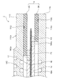
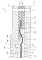
- FIG. 19 is a cross-sectional view showing a schematic configuration of the fuel cell module 20 according to this embodiment.
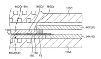
- FIG. 20 is a schematic cross-sectional view of the outer periphery of one cell in the stacked fuel cell modules 20, showing details near the boundary between the gas diffusion layer 180 and the sealing member 90.
- a cathode sealing member 90C and a cathode gas diffusion layer 180C are provided in the fuel cell module 20. Stack in the thickness direction.
- the cathode gas diffusion layer 180C overlaps the cathode sealing member 90C will be described.
- the case where the anode gas diffusion layer 180A overlaps with the sealing member 90A has the same configuration as the cathode gas diffusion layer 180C, and thus the description thereof is omitted here.
- the cathode separator 110C In the state of FIG. 20, as shown in the cross-sectional view of FIG. 19, it is sandwiched between the cathode separator 110C and the anode separator 110A. Before sandwiching the MEA 100 between the cathode separator 110C and the anode separator 110A, the outer peripheral portion of the cathode gas diffusion layer 180C is processed so as to form a space along the outer periphery. Accordingly, when a load is applied in the stacking direction, it is possible to prevent the cathode separator 110C from being damaged due to stress concentration at the portion where the cathode sealing member 90C and the cathode gas diffusion layer 180C overlap.
- a method of processing the outer peripheral portion of the cathode gas diffusion layer 180C for example, there is a method of changing the composition in the outer peripheral portion and other portions when manufacturing the cathode gas diffusion layer 180C.
- a sheet formed continuously with a uniform composition is used in the production of the cathode gas diffusion layer 180C.
- a method of processing the outer peripheral portion in the step of punching into a predetermined size is used in the production of the cathode gas diffusion layer 180C.
- FIG. 21 is a plan view of the cathode gas diffusion layer 180C.
- 22 is an enlarged view of the X3 portion of FIG. 21 when the outer peripheral portion of the cathode gas diffusion layer 180C is processed into a sawtooth shape.
- FIG. 23 is an enlarged view of a portion X3 in FIG. 21 in the case where the through hole 220b is processed in the outer peripheral portion of the cathode gas diffusion layer 180C. 21 to 23, some parts are emphasized for the sake of explanation.
- a part of the portion of the cathode gas diffusion layer 180C corresponding to the region F4 (FIG. 17) is cut out so as to penetrate in the thickness direction.
- the portion of the cathode gas diffusion layer 180C corresponding to the region F4 (FIG. 17) is an inner region F5 located inside the region F4 in the thickness direction (on the side of the polymer electrolyte membrane 150) of the cathode gas diffusion layer 180C.
- the inner area F5 is an area including spaces 220a and 220b described later.
- the cathode gas diffusion layer 180C (gas diffusion layer 180) has a first diffusion layer 180Ce and a second diffusion layer 180Cd.
- the first diffusion layer 180Ce is formed on the outer peripheral portion of the cathode gas diffusion layer 180C. Specifically, the first diffusion layer 180Ce is a portion located in the outermost layer in the plane direction of the cathode gas diffusion layer 180C. More specifically, the first diffusion layer 180Ce is a portion having spaces 220a and 220b, which will be described later, formed along the outer periphery of the outer periphery of the cathode gas diffusion layer 180C. 180 C of cathode gas diffusion layers are provided so that it may overlap with 90 C of sealing members in the thickness direction in at least one part of an outer peripheral part. In the present embodiment, the first diffusion layer 180Ce includes the inner region F5 in a part of the outer peripheral region.
- the sealing member 90A overlaps in the thickness direction in a part of the first diffusion layer 180Ce.
- the first diffusion layer 180Ce is arranged to overlap the sealing member 90C (see FIG. 20).
- the second diffusion layer 180Cd is a portion adjacent to the inside of the first diffusion layer 180Ce in the plane direction.
- the first diffusion layer 180Ce and the second diffusion layer 180Cd are formed with a uniform composition.
- the first diffusion layers 180Ce are provided at intervals in the inner area F5 (FIG. 19).
- the first diffusion layer 180Ce for example, as shown in FIG. 22, has a sawtooth portion 240 formed in a sawtooth shape in a plan view in the inner region F5.
- a space 220a is formed between the sawtooth portions 240 in the first diffusion layer 180Ce.
- the first diffusion layer 180Ce is provided with the sawtooth portion 240 on the entire outer circumference.
- the plan view refers to a state when viewed from the thickness direction.
- the first diffusion layer 180Ce may have a plurality of through holes (spaces) 220b in the inner region F5 (FIG. 19), as shown in FIG. 23, for example.
- the through hole 220b is a hole penetrating in the thickness direction of the first diffusion layer 180Ce.
- the through hole 220b is formed, for example, in a circular shape in plan view.
- the through holes 220b are, for example, uniformly provided along the outer periphery of the first diffusion layer 180Ce.
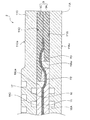
- first diffusion layer 180Ce When the outer peripheral portion (first diffusion layer 180Ce) of the cathode gas diffusion layer 180C and the cathode sealing member 90C are arranged and pressed and fastened, a load is applied to the first diffusion layer 180Ce in the thickness direction. At this time, as shown in FIG. 22 or FIG. 23, the first diffusion layer 180Ce is easily deformed and compressed in the surface direction (for example, in the direction of the arrow) toward the spaces 220a and 220b. 22 and 23, the solid line indicates the outer edge of the first diffusion layer 180Ce before deformation, and the alternate long and short dash line indicates the outer edge of the first diffusion layer 180Ce after deformation. In FIG.
- the first diffusion layer 180Ce is deformed so as to narrow the space 220a between the saw tooth portions 240.
- the first diffusion layer 180Ce deforms toward the inside of the through hole 220b so as to reduce the size of the through hole 220b.
- the outer peripheral portion (first diffusion layer 180Ce) of the cathode gas diffusion layer 180C and the cathode sealing member 90C are arranged and pressed and fastened. Also, it is possible to prevent damage to the member due to stress concentration. Therefore, the exposure of the catalyst layer can be prevented.
- the processing width of the outer peripheral portion of the cathode gas diffusion layer 180C is determined in consideration of the positional deviation accuracy when the cathode gas diffusion layer 180C and the cathode sealing member 90C are arranged in an overlapping manner. Specifically, in order to prevent the damage of the member, even if the positional deviation accuracy is deteriorated and the deviation amount is increased, the width of the processing is performed so that the cathode gas diffusion layer 180C and the cathode sealing layer are not formed in the unprocessed portion. It is determined that the stop member 90C does not overlap.
- the width of the processing is determined so that no gap is formed between the cathode gas diffusion layer 180C and the cathode sealing member 90C in order to prevent deterioration of the polymer electrolyte membrane 150, film breakage, and the like.
- the overlapping area will not be lost even if the overlapping size is reduced by 1 mm as compared with the case where the overlapping is maximized. Designed to. Further, for example, assuming that the case where the overlap is the smallest is 0.2 mm, it is possible to prevent the damage of the members by processing the outer peripheral portion of 1.2 mm or more.
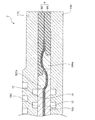
- FIG. 24 shows a schematic cross-sectional view in the case where the overlap is minimized, where the case where the overlap is maximized is shown in FIG.
- the deformation of the cathode gas diffusion layer 180C is smaller than that in the case where the overlap is maximum, in either case, it is possible to eliminate the gap in the surface direction between the cathode gas diffusion layer 180C and the sealing member 90.
- FIG. 25 shows an exemplary flowchart of a method for manufacturing the fuel cell module 20.
- the manufacturing method of the fuel cell module 20 includes a preparation step ST100, a gas diffusion layer processing step ST200, an arrangement step ST300, and an adhesion step ST400.
- the polymer electrolyte membrane 150 provided with the anode catalyst layer 160 and the cathode catalyst layer 170, the pair of gas diffusion layers 180A and 180C, the pair of sealing members 90A and 90C, and the pair of separators 110A, 110C and are prepared.
- At least one gas diffusion layer 180 reduces the volume of at least a part of the outer peripheral portion by, for example, punching.
- punching For example, when punching into a rectangular shape, the volume is reduced by cutting the outer periphery in a sawtooth shape as shown in FIG.
- the volume may be reduced, for example, by providing a plurality of through holes 220b around the entire outer peripheral portion.
- the MEA 100 including the pair of gas diffusion layers 180A and 180C and the sealing member 90 such that the outer peripheral portion of at least one gas diffusion layer 180 at least partially overlaps the sealing member 90 in the thickness direction. To place.
- the sealing members 90A, 90C and the MEA 100 are sandwiched by the pair of separators 110A, 110C, and the MEA 100 and the pair of separators 110A, 110C are bonded.
- the volume of a part of the outer peripheral portion of the cathode gas diffusion layer 180C is reduced.
- the MEA 100 including the cathode gas diffusion layer 180C and the cathode sealing member 90C are arranged such that the first diffusion layer 180Ce of the cathode gas diffusion layer 180C overlaps the sealing member 90 in the thickness direction.
- the sealing member 90 and the MEA 100 are sandwiched between the separators 110 (anode separator 110A and cathode separator 110C) and heated to bond the MEA and the separator 110.
- the fuel cell stack is completed by stacking and fastening the fuel cell modules 20 formed in this way.
- the fuel cell module includes a membrane-electrode assembly 100, a pair of separators 110A and 110C, and a sealing member 90.
- the membrane-electrode assembly 100 includes a polymer electrolyte membrane 150, an anode catalyst layer 160, a cathode catalyst layer 170, and a pair of gases in which one is laminated on the anode catalyst layer 160 and the other is laminated on the cathode catalyst layer 170. It has diffusion layers 180A and 180C.
- the anode catalyst layer 160 is provided on the first main surface of the polymer electrolyte membrane 150.
- the cathode catalyst layer 170 is provided on the second main surface of the polymer electrolyte membrane 150.
- the pair of separators 110A and 110C sandwich the membrane-electrode assembly 100.
- the sealing member 90 adheres the membrane-electrode assembly 100 to each of the pair of separators 110A and 110C.
- the opening 260 is provided in the sealing member 90 in a plan view, and one gas diffusion layer 180 of the pair of gas diffusion layers 180A and 180C and the sealing member 90 are the regions including the edge 260a of the opening 260. Overlap in the thickness direction at F4. A part of a portion (inner region F5) of the one gas diffusion layer 180 corresponding to the region F4 penetrates in the thickness direction and is cut out.
- a space 220a, 220b for the first diffusion layer 180Ce to be deformed in the surface direction can be formed by partially cutting out the inner region F5 in the thickness direction. it can. Accordingly, when a load is applied to the first diffusion layer 180Ce in the thickness direction, the first diffusion layer 180Ce can be deformed toward the spaces 220a and 220b. Accordingly, even if a load is applied in a state where the gas diffusion layer 180 and the sealing member 90 overlap each other in the thickness direction, it is possible to prevent stress concentration on the constituent members. As a result, even when the outer peripheral portion of the gas diffusion layer 180 and the sealing member 90 overlap, stress concentration on the constituent members can be prevented and deterioration of the polymer electrolyte membrane 150 can be suppressed.
- a plurality of through holes 220b penetrating in the thickness direction is provided in a portion (inner region F5) of the one gas diffusion layer 180 corresponding to the region F4.
- the first diffusion layer 180Ce when a load is applied to the first diffusion layer 180Ce in the thickness direction, the first diffusion layer 180Ce can be deformed toward the through hole 220b.
- a saw tooth portion 240 formed in a saw tooth shape in a plan view is provided in a portion (inner region F5) of the one gas diffusion layer 180 corresponding to the region F4.
- the first diffusion layer 180Ce when a load is applied to the first diffusion layer 180Ce in the thickness direction, the first diffusion layer 180Ce can be deformed toward the space 220a between the saw tooth portions 240.
- the fuel cell stack according to the present embodiment includes a plurality of fuel cell modules 20.
- the method for manufacturing the fuel cell module according to the present embodiment includes a processing step ST200, an arrangement step ST300, and an adhesion step ST400.
- the processing step ST200 the volume of at least a part of the outer peripheral portion of at least one of the pair of gas diffusion layers 180A and 180C is reduced.
- the membrane-electrode assembly 100 including the pair of gas diffusion layers 180A and 180C is formed so that the outer peripheral portion of at least one gas diffusion layer 180 at least partially overlaps the sealing member 90 in the thickness direction.
- the sealing member 90 is arranged.
- the sealing member 90 and the membrane-electrode assembly 100 are sandwiched by the pair of separators 110A and 110C, and the membrane-electrode assembly 100 and the pair of separators 110A and 110C are bonded.
- the present invention is not limited to the above-mentioned embodiment, but can be implemented in various other modes.
- the configuration in which the cathode gas diffusion layer 180C and the cathode sealing member 90C are arranged to overlap each other on the cathode side has been described as an example, but the fuel cell module 20 is not limited to this.
- the fuel cell module 20 may have a configuration in which the anode gas diffusion layer 180A and the anode sealing member 90A are arranged so as to overlap each other on the anode side.
- a part of the portion corresponding to the region F4 may be cut out so as to penetrate in the thickness direction.
- stress concentration on the constituent members can be prevented and deterioration of the polymer electrolyte membrane 150 can be suppressed.
- a part of the portion corresponding to the region F4 may be cut out by penetrating in the thickness direction. Also with this configuration, even when the outer peripheral portion of the gas diffusion layer 180 and the sealing member 90 overlap, stress concentration on the constituent members can be prevented and deterioration of the polymer electrolyte membrane 150 can be suppressed.
- At least one of the gas diffusion layers 180 is supposed to reduce the volume of at least a part of the outer peripheral portion by punching, but the invention is not limited to the punching as long as the volume of at least a part of the outer peripheral portion can be reduced.
- the first diffusion layer 180Ce has the sawtooth portion 240 formed in a sawtooth shape in a plan view, but in the gas diffusion layer 180 of at least one of the pair of gas diffusion layers 180A and 180C, it is formed in the region F4.
- the present invention is not limited to this as long as a part of the corresponding portion is cut through in the thickness direction.
- the first diffusion layer 180Ce may be formed so as to be curved in the surface direction along the outer circumference, for example. Also with this configuration, even if a load is applied in a state in which the gas diffusion layers 180A and 180C and the sealing members 90A and 90C overlap in the thickness direction, stress concentration on the constituent members can be prevented.
- the through hole 220b is formed in a circular shape in plan view, but the shape is not limited to this.
- the shape of the through hole 220b may be another shape such as an ellipse or a polygon in a plan view.
- the sealing member 90A overlaps with the thickness direction in a part of the first diffusion layer 180Ce
- the sealing member 90A overlaps with the entire first diffusion layer 180Ce in the thickness direction in a plan view. May be. That is, in plan view, the inner edge of the inner region F5 (two-dot chain line in FIG. 21) and the inner edge of the first diffusion layer 180Ce (dotted line in FIG. 21) may match.
- a highly durable thin fuel cell module is provided while suppressing external leakage or cross leakage of the fuel gas and the oxidant gas. realizable. Therefore, it is useful as, for example, a portable power source, a power source for an electric vehicle, a fuel cell used in a home cogeneration system, or the like.
Landscapes
- Life Sciences & Earth Sciences (AREA)
- Engineering & Computer Science (AREA)
- Manufacturing & Machinery (AREA)
- Sustainable Development (AREA)
- Sustainable Energy (AREA)
- Chemical & Material Sciences (AREA)
- Chemical Kinetics & Catalysis (AREA)
- Electrochemistry (AREA)
- General Chemical & Material Sciences (AREA)
- Fuel Cell (AREA)
Abstract
L'invention concerne un module de piles à combustible pourvu d'une membrane électrolytique polymère qui n'est pas susceptible de se dégrader. Le module de piles à combustible comprend : un ensemble membrane-électrode pourvu d'une membrane électrolytique polymère, une couche de catalyseur d'anode disposée sur une première surface principale de la membrane électrolytique polymère, une couche de catalyseur de cathode disposée sur une seconde surface principale de la membrane électrolytique polymère, et une paire de couches de diffusion de gaz dont l'une est stratifiée sur la couche de catalyseur d'anode et l'autre est stratifiée sur la couche de catalyseur de cathode; une paire de séparateurs entre lesquels est pris en sandwich l'ensemble membrane-électrode; et un élément d'étanchéité pour assurer l'étanchéité par liaison de l'ensemble membrane-électrode et de chaque séparateur de la paire de séparateurs, une couche de la paire de couches de diffusion de gaz et l'élément d'étanchéité se chevauchant mutuellement dans le sens de l'épaisseur dans une région comprenant le bord d'extrémité côté centre de l'élément d'étanchéité, et une partie d'une portion correspondant à la région dans l'une des couches de diffusion de gaz est entaillée dans le sens de l'épaisseur.
Priority Applications (3)
| Application Number | Priority Date | Filing Date | Title |
|---|---|---|---|
| JP2020559120A JP7349641B2 (ja) | 2018-12-11 | 2019-11-28 | 燃料電池モジュールおよび燃料電池スタック、ならびに燃料電池モジュールの製造方法 |
| CN201980081646.8A CN113169341A (zh) | 2018-12-11 | 2019-11-28 | 燃料电池模块以及燃料电池组、和燃料电池模块的制造方法 |
| US17/312,588 US20210336279A1 (en) | 2018-12-11 | 2019-11-28 | Fuel cell module, fuel cell stack, and manufacturing method of fuel cell module |
Applications Claiming Priority (4)
| Application Number | Priority Date | Filing Date | Title |
|---|---|---|---|
| JP2018-231860 | 2018-12-11 | ||
| JP2018231860 | 2018-12-11 | ||
| JP2019-070624 | 2019-04-02 | ||
| JP2019070624 | 2019-04-02 |
Publications (1)
| Publication Number | Publication Date |
|---|---|
| WO2020121830A1 true WO2020121830A1 (fr) | 2020-06-18 |
Family
ID=71076034
Family Applications (1)
| Application Number | Title | Priority Date | Filing Date |
|---|---|---|---|
| PCT/JP2019/046603 WO2020121830A1 (fr) | 2018-12-11 | 2019-11-28 | Module de piles à combustible, asemblage de piles à combustible et procédé de fabrication de module de piles à combustible |
Country Status (4)
| Country | Link |
|---|---|
| US (1) | US20210336279A1 (fr) |
| JP (1) | JP7349641B2 (fr) |
| CN (1) | CN113169341A (fr) |
| WO (1) | WO2020121830A1 (fr) |
Cited By (1)
| Publication number | Priority date | Publication date | Assignee | Title |
|---|---|---|---|---|
| CN112563531A (zh) * | 2020-12-03 | 2021-03-26 | 中国科学院大连化学物理研究所 | 一种燃料电池电堆封装结构 |
Families Citing this family (1)
| Publication number | Priority date | Publication date | Assignee | Title |
|---|---|---|---|---|
| KR20210132342A (ko) * | 2020-04-27 | 2021-11-04 | 현대자동차주식회사 | 막-전극 접합체용 전극 및 이의 제조방법 |
Citations (4)
| Publication number | Priority date | Publication date | Assignee | Title |
|---|---|---|---|---|
| JPH10154521A (ja) * | 1996-09-24 | 1998-06-09 | Matsushita Electric Ind Co Ltd | 固体高分子型燃料電池 |
| JP2005235736A (ja) * | 2004-01-22 | 2005-09-02 | Aisin Seiki Co Ltd | 燃料電池用膜電極接合体及びその製造方法、燃料電池 |
| JP2007503688A (ja) * | 2003-08-22 | 2007-02-22 | ジョンソン、マッセイ、パブリック、リミテッド、カンパニー | メンブラン電極組立構造の密封 |
| JP2013098044A (ja) * | 2011-11-01 | 2013-05-20 | Honda Motor Co Ltd | 燃料電池 |
Family Cites Families (11)
| Publication number | Priority date | Publication date | Assignee | Title |
|---|---|---|---|---|
| JP4515631B2 (ja) * | 1997-10-28 | 2010-08-04 | 株式会社東芝 | ガスマニホールドを備えた燃料電池 |
| US20050064275A1 (en) * | 2003-09-18 | 2005-03-24 | 3M Innovative Properties Company | Fuel cell gas diffusion layer |
| JP4337587B2 (ja) * | 2004-03-12 | 2009-09-30 | 日産自動車株式会社 | インターコネクタ及び燃料電池スタック |
| CN101356675B (zh) * | 2006-06-26 | 2011-01-05 | 松下电器产业株式会社 | 固体高分子电解质型燃料电池 |
| US8012284B2 (en) * | 2006-12-15 | 2011-09-06 | 3M Innovative Properties Company | Method and apparatus for fabricating roll good fuel cell subassemblies |
| JP5435224B2 (ja) * | 2009-10-28 | 2014-03-05 | Nok株式会社 | 燃料電池用シール構造体の製造方法 |
| JP5461364B2 (ja) * | 2010-11-01 | 2014-04-02 | 三菱重工業株式会社 | 燃料電池用集電棒のシール構造 |
| CA2989526C (fr) * | 2015-06-15 | 2020-11-10 | Nissan Motor Co., Ltd. | Structure d'electrode de pile a combustible, separateur metallique, pile a combustible utilisant ladite structure d'electrode de pile a combustible et ledit separateur metallique,et matrice de fabrication de ladite structure d'electrode de pile a combustible |
| CN107146904B (zh) * | 2017-04-07 | 2020-04-07 | 上海电气集团股份有限公司 | 燃料电池端板组合、远处端板组合、进口端板组合及电堆 |
| DE102018115987A1 (de) * | 2018-07-02 | 2020-01-02 | Elringklinger Ag | Verfahren zum Erzeugen eines Dichtelements an einer Gasdiffusionslage einer elektrochemischen Einheit und Baugruppe aus einer Gasdiffusionslage und einem Dichtelement |
| JP7056504B2 (ja) * | 2018-10-10 | 2022-04-19 | トヨタ自動車株式会社 | 膜電極接合体プレートの製造装置 |
-
2019
- 2019-11-28 JP JP2020559120A patent/JP7349641B2/ja active Active
- 2019-11-28 WO PCT/JP2019/046603 patent/WO2020121830A1/fr active Application Filing
- 2019-11-28 US US17/312,588 patent/US20210336279A1/en active Pending
- 2019-11-28 CN CN201980081646.8A patent/CN113169341A/zh active Pending
Patent Citations (4)
| Publication number | Priority date | Publication date | Assignee | Title |
|---|---|---|---|---|
| JPH10154521A (ja) * | 1996-09-24 | 1998-06-09 | Matsushita Electric Ind Co Ltd | 固体高分子型燃料電池 |
| JP2007503688A (ja) * | 2003-08-22 | 2007-02-22 | ジョンソン、マッセイ、パブリック、リミテッド、カンパニー | メンブラン電極組立構造の密封 |
| JP2005235736A (ja) * | 2004-01-22 | 2005-09-02 | Aisin Seiki Co Ltd | 燃料電池用膜電極接合体及びその製造方法、燃料電池 |
| JP2013098044A (ja) * | 2011-11-01 | 2013-05-20 | Honda Motor Co Ltd | 燃料電池 |
Cited By (2)
| Publication number | Priority date | Publication date | Assignee | Title |
|---|---|---|---|---|
| CN112563531A (zh) * | 2020-12-03 | 2021-03-26 | 中国科学院大连化学物理研究所 | 一种燃料电池电堆封装结构 |
| CN112563531B (zh) * | 2020-12-03 | 2022-02-11 | 中国科学院大连化学物理研究所 | 一种燃料电池电堆封装结构 |
Also Published As
| Publication number | Publication date |
|---|---|
| CN113169341A (zh) | 2021-07-23 |
| US20210336279A1 (en) | 2021-10-28 |
| JP7349641B2 (ja) | 2023-09-25 |
| JPWO2020121830A1 (ja) | 2021-10-28 |
Similar Documents
| Publication | Publication Date | Title |
|---|---|---|
| US7195838B2 (en) | Membrane electrode assembly and fuel cell | |
| KR100876262B1 (ko) | 고체 고분자 전해질형 연료전지 | |
| US9490497B2 (en) | Solid polymer electrolyte type fuel cell, and electrolyte membrane-electrode-frame assembly | |
| US20090004540A1 (en) | Fuel Cell and Laminate | |
| US8329322B2 (en) | Electrode-membrane-frame assembly for polyelectrolyte fuel cell, manufacturing method therefor, and polyelectrolyte fuel cell | |
| JP6375522B2 (ja) | 燃料電池モジュールの製造方法 | |
| JP7349641B2 (ja) | 燃料電池モジュールおよび燃料電池スタック、ならびに燃料電池モジュールの製造方法 | |
| US20090053581A1 (en) | Separator and fuel cell | |
| JP2005183210A (ja) | 燃料電池のシール構造 | |
| JP2019139993A (ja) | 燃料電池モジュールおよびその製造方法 | |
| JP2004349014A (ja) | 燃料電池 | |
| JP7394317B2 (ja) | 燃料電池モジュールおよび燃料電池スタック、ならびに燃料電池モジュールの製造方法 | |
| JP2016225274A (ja) | 接合体とその接合体を用いた燃料電池、ならびに、その分解方法 | |
| JP7398636B2 (ja) | 燃料電池モジュール及びその製造方法 | |
| JP2006338880A (ja) | 膜−電極接合体および燃料電池 | |
| JP5280414B2 (ja) | 膜・電極構造体および燃料電池 | |
| JP2008218197A (ja) | 燃料電池及び燃料電池スタック | |
| JP6945175B2 (ja) | 燃料電池セル積層体およびその製造方法 | |
| JP7018580B2 (ja) | 高分子電解質型燃料電池とその製造方法 | |
| CN117059831A (zh) | 燃料电池堆 | |
| JP2006269264A (ja) | 固体高分子電解質形燃料電池 | |
| JP2019175803A (ja) | 燃料電池スタックおよびその製造方法 |
Legal Events
| Date | Code | Title | Description |
|---|---|---|---|
| 121 | Ep: the epo has been informed by wipo that ep was designated in this application |
Ref document number: 19897201 Country of ref document: EP Kind code of ref document: A1 |
|
| ENP | Entry into the national phase |
Ref document number: 2020559120 Country of ref document: JP Kind code of ref document: A |
|
| NENP | Non-entry into the national phase |
Ref country code: DE |
|
| 122 | Ep: pct application non-entry in european phase |
Ref document number: 19897201 Country of ref document: EP Kind code of ref document: A1 |