WO2020116293A1 - リアクトル - Google Patents
リアクトル Download PDFInfo
- Publication number
- WO2020116293A1 WO2020116293A1 PCT/JP2019/046467 JP2019046467W WO2020116293A1 WO 2020116293 A1 WO2020116293 A1 WO 2020116293A1 JP 2019046467 W JP2019046467 W JP 2019046467W WO 2020116293 A1 WO2020116293 A1 WO 2020116293A1
- Authority
- WO
- WIPO (PCT)
- Prior art keywords
- core portion
- inner core
- hole
- reactor
- connecting shaft
- Prior art date
- Legal status (The legal status is an assumption and is not a legal conclusion. Google has not performed a legal analysis and makes no representation as to the accuracy of the status listed.)
- Ceased
Links
Images



Classifications
-
- H—ELECTRICITY
- H01—ELECTRIC ELEMENTS
- H01F—MAGNETS; INDUCTANCES; TRANSFORMERS; SELECTION OF MATERIALS FOR THEIR MAGNETIC PROPERTIES
- H01F3/00—Cores, Yokes, or armatures
- H01F3/10—Composite arrangements of magnetic circuits
-
- H—ELECTRICITY
- H01—ELECTRIC ELEMENTS
- H01F—MAGNETS; INDUCTANCES; TRANSFORMERS; SELECTION OF MATERIALS FOR THEIR MAGNETIC PROPERTIES
- H01F1/00—Magnets or magnetic bodies characterised by the magnetic materials therefor; Selection of materials for their magnetic properties
- H01F1/01—Magnets or magnetic bodies characterised by the magnetic materials therefor; Selection of materials for their magnetic properties of inorganic materials
- H01F1/03—Magnets or magnetic bodies characterised by the magnetic materials therefor; Selection of materials for their magnetic properties of inorganic materials characterised by their coercivity
- H01F1/12—Magnets or magnetic bodies characterised by the magnetic materials therefor; Selection of materials for their magnetic properties of inorganic materials characterised by their coercivity of soft-magnetic materials
- H01F1/14—Magnets or magnetic bodies characterised by the magnetic materials therefor; Selection of materials for their magnetic properties of inorganic materials characterised by their coercivity of soft-magnetic materials metals or alloys
- H01F1/20—Magnets or magnetic bodies characterised by the magnetic materials therefor; Selection of materials for their magnetic properties of inorganic materials characterised by their coercivity of soft-magnetic materials metals or alloys in the form of particles, e.g. powder
-
- H—ELECTRICITY
- H01—ELECTRIC ELEMENTS
- H01F—MAGNETS; INDUCTANCES; TRANSFORMERS; SELECTION OF MATERIALS FOR THEIR MAGNETIC PROPERTIES
- H01F1/00—Magnets or magnetic bodies characterised by the magnetic materials therefor; Selection of materials for their magnetic properties
- H01F1/01—Magnets or magnetic bodies characterised by the magnetic materials therefor; Selection of materials for their magnetic properties of inorganic materials
- H01F1/03—Magnets or magnetic bodies characterised by the magnetic materials therefor; Selection of materials for their magnetic properties of inorganic materials characterised by their coercivity
- H01F1/12—Magnets or magnetic bodies characterised by the magnetic materials therefor; Selection of materials for their magnetic properties of inorganic materials characterised by their coercivity of soft-magnetic materials
- H01F1/14—Magnets or magnetic bodies characterised by the magnetic materials therefor; Selection of materials for their magnetic properties of inorganic materials characterised by their coercivity of soft-magnetic materials metals or alloys
- H01F1/20—Magnets or magnetic bodies characterised by the magnetic materials therefor; Selection of materials for their magnetic properties of inorganic materials characterised by their coercivity of soft-magnetic materials metals or alloys in the form of particles, e.g. powder
- H01F1/22—Magnets or magnetic bodies characterised by the magnetic materials therefor; Selection of materials for their magnetic properties of inorganic materials characterised by their coercivity of soft-magnetic materials metals or alloys in the form of particles, e.g. powder pressed, sintered, or bound together
- H01F1/24—Magnets or magnetic bodies characterised by the magnetic materials therefor; Selection of materials for their magnetic properties of inorganic materials characterised by their coercivity of soft-magnetic materials metals or alloys in the form of particles, e.g. powder pressed, sintered, or bound together the particles being insulated
- H01F1/26—Magnets or magnetic bodies characterised by the magnetic materials therefor; Selection of materials for their magnetic properties of inorganic materials characterised by their coercivity of soft-magnetic materials metals or alloys in the form of particles, e.g. powder pressed, sintered, or bound together the particles being insulated by macromolecular organic substances
-
- H—ELECTRICITY
- H01—ELECTRIC ELEMENTS
- H01F—MAGNETS; INDUCTANCES; TRANSFORMERS; SELECTION OF MATERIALS FOR THEIR MAGNETIC PROPERTIES
- H01F27/00—Details of transformers or inductances, in general
- H01F27/24—Magnetic cores
- H01F27/255—Magnetic cores made from particles
-
- H—ELECTRICITY
- H01—ELECTRIC ELEMENTS
- H01F—MAGNETS; INDUCTANCES; TRANSFORMERS; SELECTION OF MATERIALS FOR THEIR MAGNETIC PROPERTIES
- H01F27/00—Details of transformers or inductances, in general
- H01F27/24—Magnetic cores
- H01F27/26—Fastening parts of the core together; Fastening or mounting the core on casing or support
- H01F27/263—Fastening parts of the core together
-
- H—ELECTRICITY
- H01—ELECTRIC ELEMENTS
- H01F—MAGNETS; INDUCTANCES; TRANSFORMERS; SELECTION OF MATERIALS FOR THEIR MAGNETIC PROPERTIES
- H01F27/00—Details of transformers or inductances, in general
- H01F27/28—Coils; Windings; Conductive connections
- H01F27/2823—Wires
-
- H—ELECTRICITY
- H01—ELECTRIC ELEMENTS
- H01F—MAGNETS; INDUCTANCES; TRANSFORMERS; SELECTION OF MATERIALS FOR THEIR MAGNETIC PROPERTIES
- H01F3/00—Cores, Yokes, or armatures
- H01F3/08—Cores, Yokes, or armatures made from powder
-
- H—ELECTRICITY
- H01—ELECTRIC ELEMENTS
- H01F—MAGNETS; INDUCTANCES; TRANSFORMERS; SELECTION OF MATERIALS FOR THEIR MAGNETIC PROPERTIES
- H01F3/00—Cores, Yokes, or armatures
- H01F3/10—Composite arrangements of magnetic circuits
- H01F3/14—Constrictions; Gaps, e.g. air-gaps
-
- H—ELECTRICITY
- H01—ELECTRIC ELEMENTS
- H01F—MAGNETS; INDUCTANCES; TRANSFORMERS; SELECTION OF MATERIALS FOR THEIR MAGNETIC PROPERTIES
- H01F37/00—Fixed inductances not covered by group H01F17/00
-
- H—ELECTRICITY
- H01—ELECTRIC ELEMENTS
- H01F—MAGNETS; INDUCTANCES; TRANSFORMERS; SELECTION OF MATERIALS FOR THEIR MAGNETIC PROPERTIES
- H01F41/00—Apparatus or processes specially adapted for manufacturing or assembling magnets, inductances or transformers; Apparatus or processes specially adapted for manufacturing materials characterised by their magnetic properties
- H01F41/02—Apparatus or processes specially adapted for manufacturing or assembling magnets, inductances or transformers; Apparatus or processes specially adapted for manufacturing materials characterised by their magnetic properties for manufacturing cores, coils, or magnets
- H01F41/0206—Manufacturing of magnetic cores by mechanical means
- H01F41/0246—Manufacturing of magnetic circuits by moulding or by pressing powder
-
- H—ELECTRICITY
- H01—ELECTRIC ELEMENTS
- H01F—MAGNETS; INDUCTANCES; TRANSFORMERS; SELECTION OF MATERIALS FOR THEIR MAGNETIC PROPERTIES
- H01F1/00—Magnets or magnetic bodies characterised by the magnetic materials therefor; Selection of materials for their magnetic properties
- H01F1/01—Magnets or magnetic bodies characterised by the magnetic materials therefor; Selection of materials for their magnetic properties of inorganic materials
- H01F1/03—Magnets or magnetic bodies characterised by the magnetic materials therefor; Selection of materials for their magnetic properties of inorganic materials characterised by their coercivity
- H01F1/12—Magnets or magnetic bodies characterised by the magnetic materials therefor; Selection of materials for their magnetic properties of inorganic materials characterised by their coercivity of soft-magnetic materials
- H01F1/14—Magnets or magnetic bodies characterised by the magnetic materials therefor; Selection of materials for their magnetic properties of inorganic materials characterised by their coercivity of soft-magnetic materials metals or alloys
- H01F1/20—Magnets or magnetic bodies characterised by the magnetic materials therefor; Selection of materials for their magnetic properties of inorganic materials characterised by their coercivity of soft-magnetic materials metals or alloys in the form of particles, e.g. powder
- H01F1/22—Magnets or magnetic bodies characterised by the magnetic materials therefor; Selection of materials for their magnetic properties of inorganic materials characterised by their coercivity of soft-magnetic materials metals or alloys in the form of particles, e.g. powder pressed, sintered, or bound together
- H01F1/24—Magnets or magnetic bodies characterised by the magnetic materials therefor; Selection of materials for their magnetic properties of inorganic materials characterised by their coercivity of soft-magnetic materials metals or alloys in the form of particles, e.g. powder pressed, sintered, or bound together the particles being insulated
-
- H—ELECTRICITY
- H01—ELECTRIC ELEMENTS
- H01F—MAGNETS; INDUCTANCES; TRANSFORMERS; SELECTION OF MATERIALS FOR THEIR MAGNETIC PROPERTIES
- H01F3/00—Cores, Yokes, or armatures
- H01F3/10—Composite arrangements of magnetic circuits
- H01F2003/106—Magnetic circuits using combinations of different magnetic materials
Definitions
- Patent Document 1 discloses a reactor including a coil having a winding portion formed by winding a winding wire and a magnetic core forming a closed magnetic circuit.
- the magnetic core of this reactor can be divided into an inner core portion arranged inside the winding portion and an outer core portion arranged outside the winding portion.
- a magnetic core is formed by connecting an inner core portion formed by combining a plurality of core pieces and a gap member, which are independent of each other, and a core piece forming the outer core portion with a bolt member.
- the reactor of the present disclosure is A coil having a winding portion, A reactor comprising an inner core portion arranged inside the winding portion, and a magnetic core having an outer core portion arranged outside the winding portion,
- the magnetic core is A communication hole that penetrates the outer core portion and reaches the inner core portion,
- a connecting shaft configured of a composite material filled in the communication hole, the connecting shaft connecting the inner core portion and the outer core portion,
- the composite material is formed by dispersing soft magnetic powder in resin.
- FIG. 1 is a perspective view of the reactor according to the first embodiment.
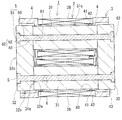
- FIG. 2 is a horizontal sectional view of the reactor of FIG.
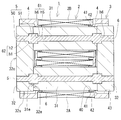
- FIG. 3 is a horizontal sectional view of the reactor of the second embodiment.
- FIG. 4 is a horizontal sectional view of the reactor of the third embodiment.
- FIG. 5 is a horizontal sectional view of the reactor of the fourth embodiment.
- Patent Document 1 it is possible to accurately connect a plurality of core pieces. Further, since the bolt members that connect the core pieces are arranged so as to penetrate all the core pieces and are not arranged outside the coils, it is possible to suppress the reactor from becoming large due to the bolt members. However, with the configuration of Patent Document 1, there is room for improvement in terms of productivity, and there is also a possibility that the magnetic characteristics may deteriorate.
- the inner core part is composed of a plurality of core pieces and gap members, it is necessary to provide through holes in each core piece and the gap member. Further, the work of aligning the core piece and the gap member and the work of penetrating the bolt member in alignment with the through holes of each member are complicated.
- the bolt member is arranged in the portion that becomes the magnetic path, and the magnetic characteristics of the reactor are not good. This is because the material of the bolt member of Patent Document 1 is selected in consideration of the strength of tightening by the bolt member, and is not considered to be selected in consideration of the magnetic characteristics of the reactor.
- the reactor of the present disclosure has excellent magnetic properties and can be manufactured with high productivity by a simple procedure.
- a coil having a winding portion A reactor comprising an inner core portion arranged inside the winding portion, and a magnetic core having an outer core portion arranged outside the winding portion,
- the magnetic core is A communication hole that penetrates the outer core portion and reaches the inner core portion,
- the composite material is formed by dispersing soft magnetic powder in resin.
- the inner core portion and the outer core portion are aligned, and the composite material is filled in the communication hole that penetrates the outer core portion and reaches the inner core portion.
- the softened resin of the composite material adheres to the communication hole, the communication hole and the connecting shaft of the composite material are fused over the entire length with almost no gap, and the outer core portion and the inner core portion are connected by the connecting shaft. ..
- the reactor can be completed only by filling the communication hole with the composite material, so that the productivity of the reactor can be improved.
- the magnetic characteristics required for the reactor are unlikely to deteriorate. This is because the connecting shaft that connects the inner core portion and the outer core portion is made of a composite material, so that the reduction in magnetic characteristics required for the magnetic core of the reactor is suppressed.
- Each of the inner core portion and the outer core portion may be in the form of a non-divided structure.
- Each of the inner core portion and the outer core portion may be a combination of divided pieces, but if the inner core portion and the outer core portion are integrally formed of a non-divided structure, the inner core portion and the outer portion at the time of manufacturing the reactor Positioning with the core part becomes easy. As a result, the productivity of the reactor can be improved.
- connection shaft may include a retaining portion that is hooked on the inner peripheral surface of the communication hole in the axial direction.
- the connecting shaft will not easily mechanically come off the magnetic core.
- the connection between the inner core portion and the outer core portion by the connecting shaft can be made stronger.
- the structure of the retaining portion is not particularly limited.
- the retaining portion may be formed by a thread-shaped irregularity formed on the outer peripheral surface of the connecting shaft.
- the connecting shaft includes a projecting portion that projects in a direction intersecting the axial direction,
- the retaining portion may be in the form of the protruding portion.
- the connecting shaft is a retaining part that consists of an overhanging part that extends in a direction that intersects the axial direction of the connecting part, it is possible to reliably prevent the connecting shaft from coming off the magnetic core.
- the overhanging portion include a thick shaft portion where the cross-sectional area of the connecting shaft is locally increased.
- an intersecting axis that intersects the axial direction of the connecting axis can be cited.
- ⁇ 5> As one form of the reactor of ⁇ 3> or ⁇ 4> above, An example is a form in which the retaining portion is formed inside the outer core portion.
- the retaining portion of the connecting shaft is formed inside the inner core portion, the inner core portion and the outer core portion can be connected more firmly.
- the overhanging part By forming the overhanging part so as to straddle the outer core part and the inner core part, it is possible to suppress an increase in reactor loss.
- a gap air gap
- the overhanging portion is formed across both core portions, the facing area of both core portions is reduced by the amount of the overhanging portion. As a result, it becomes difficult to form an air gap at the boundary between both core portions, so that it is possible to suppress an increase in reactor loss.
- the composite material contains a resin, it has better machinability than a powder compact formed by pressing soft magnetic powder. As shown in an embodiment described later, since a communication hole having a complicated shape may be formed especially in the inner core portion, it is preferable to form the inner core portion with a composite material having excellent machinability.
- the inner core part By configuring the inner core part with a composite material, it becomes easier to adjust the magnetic characteristics of the entire reactor. This is because the magnetic characteristics of the composite material can be easily adjusted by adjusting the content of the soft magnetic powder of the composite material. In particular, when the inner core portion and the outer core portion are independent moldings, there is only room for interposing the gap member between the inner core portion and the outer core portion, and the magnetic characteristics of the entire reactor are adjusted. hard. In contrast to this configuration, it is effective to configure the inner core portion with a composite material.
- An example is a form in which the outer core portion is made of a soft magnetic powder compact.
- the green compact easily increases the soft magnetic powder content, and by increasing the content, it is easy to increase the saturation magnetic flux density and relative permeability of the green compact.
- the inner core portion is made of a composite material and the outer core portion is made of a powder compact, a reactor having extremely excellent magnetic characteristics can be obtained.
- the reactor 1 shown in FIG. 1 is configured by combining a coil 2, a magnetic core 3 and a holding member 4.
- the magnetic core 3 includes an inner core portion 31 and an outer core portion 32.
- One of the features of the reactor 1 is that the inner core portion 31 and the outer core portion 32 are integrally formed of a non-divided structure, and the inner core portion 31 and the outer core portion 32 are connected by a connecting shaft 5 of a composite material. That is being done.
- each component provided in the reactor 1 will be described in detail.
- the coil 2 of the present embodiment includes a pair of winding portions 2A and 2B and a connecting portion 2R that connects the winding portions 2A and 2B.
- the winding portions 2A and 2B are formed in a hollow cylindrical shape with the same number of windings and the same winding direction, and are arranged in parallel so that their axial directions are parallel to each other.
- the coil 2 is manufactured by connecting the winding portions 2A and 2B which are manufactured by the separate windings 2w, but the coil 2 can be manufactured by using one winding 2w.
- Each winding part 2A, 2B of this embodiment is formed in a rectangular tube shape.
- the rectangular tube-shaped winding portions 2A and 2B are winding portions whose end faces have a quadrangular shape (including a square shape) with rounded corners.
- the winding parts 2A and 2B may be formed in a cylindrical shape.
- the cylindrical winding portion is a winding portion whose end surface shape is a closed curved surface shape (elliptical shape, perfect circle shape, race track shape, etc.).
- the coil 2 including the wound portions 2A and 2B is a covered wire having an insulating coating made of an insulating material on the outer periphery of a conductor such as a rectangular wire or a round wire made of a conductive material such as copper, aluminum, magnesium, or an alloy thereof.
- a conductor such as a rectangular wire or a round wire made of a conductive material such as copper, aluminum, magnesium, or an alloy thereof.
- the conductor is made of a copper rectangular wire (winding 2w), and the insulating rectangular wire made of enamel (typically polyamide imide) is wound edgewise to form each winding portion 2A, 2B is formed.
- Both ends 2a and 2b of the coil 2 are extended from the winding portions 2A and 2B and connected to a terminal member (not shown).
- the insulating coating such as enamel is peeled off at both ends 2a and 2b.
- an external device such as a power source for supplying electric power to the coil 2 is connected.
- the magnetic core 3 includes inner core portions 31, 31 arranged inside the winding portion 2A and the winding portion 2B, and outer core portions 32, 32 forming a closed magnetic path with the inner core portions 31, 31. , Is provided.
- the magnetic core 3 of this example has a gapless structure in which a gap member is not arranged between the inner core portion 31 and the outer core portion 32, but a structure including a gap member may be used.
- the inner core portion 31 is a portion of the magnetic core 3 along the axial direction of the winding portions 2A and 2B of the coil 2.
- both ends of the magnetic core 3 along the axial direction of the winding portions 2A and 2B project from the end faces of the winding portions 2A and 2B (FIG. 2).
- the protruding portion is also a part of the inner core portion 31.
- the end portion of the inner core portion 31 protruding from the winding portions 2A and 2B is inserted into a through hole 40 of the holding member 4 described later.
- the shape of the inner core portion 31 is not particularly limited as long as it is a shape that follows the inner shape of the winding portion 2A (2B).
- the inner core portion 31 of this example has a substantially rectangular parallelepiped shape.
- the inner core portion 31 is a non-divided, one-piece structure, which is one of the factors that facilitate the assembly of the reactor 1.
- the inner core portion 31 can also be configured by combining a plurality of split cores.
- the inner core portion 31 may be formed by interposing a gap plate between the split cores.
- the axial end surface 31e of the inner core portion 31 is in contact with the inner surface 32e of the outer core portion 32, which will be described later (FIG. 2).
- An adhesive may be interposed between the end surface 31e and the inner surface 32e, but it does not have to be provided. This is because the inner core portion 31 and the outer core portion 32 are connected by the connecting shaft 5, as described later.
- the peripheral surface 31s excluding the end surface 31e faces the inner peripheral surfaces of the winding portions 2A and 2B, but does not contact the inner peripheral surface, and the inner peripheral surface thereof. It is held in a position away from. This is because both the inner core portion 31 and the winding portions 2A and 2B mechanically engage with a holding member 4 described later, and the relative positions of the inner core portion 31 and the winding portions 2A and 2B are determined. Because it is.
- the inner core portion 31 of this example further includes an inner core hole 61.
- the inner core hole 61 of this example is a through hole that penetrates the inner core portion 31 in the axial direction.
- the inner core hole 61 has a uniform inner peripheral surface shape in the axial direction.
- the inner core hole 61 constitutes a part of the communication hole 6 described later.
- a connecting shaft 5 made of a composite material is arranged inside the inner core hole 61.
- the composite material is a material that can be a constituent material of the magnetic core 3 as described later. Therefore, the portion of the connecting shaft 5 arranged inside the inner core hole 61 may be considered as a part of the inner core portion 31.
- the inner core hole 61 of this example has a circular cross section orthogonal to the axial direction.
- the shape of the cross section of the inner core hole 61 is not particularly limited, and may be, for example, a polygonal shape such as a quadrangle or a pentagon.
- the axis of the inner core hole 61 of this example matches the axis of the inner core portion 31.
- the inner core hole 61 may be inclined with respect to the axial direction of the inner core portion 31.
- the cross-sectional area of the inner core hole 61 is not particularly limited.
- the cross-sectional area of the inner core portion 31 when the cross-sectional area of the inner core portion 31 is 100%, the cross-sectional area of the inner core hole 61 may be 5% or more and 30% or less.
- the area of the cross section of the inner core hole 61 with respect to the inner core portion 31 is preferably 10% or more and 25% or less, and more preferably 10% or more and 20% or less.
- the inner core hole 61 can be formed by a mold when the inner core portion 31 is molded. Further, the inner core hole 61 can also be formed by processing. In this case, the inner core hole 61 can be formed by forming a hole in the end surface 31e after forming the inner core portion 31 with a drill or the like.
- the outer core portion 32 is a portion of the magnetic core 3 arranged outside the winding portions 2A and 2B (FIG. 1).
- the shape of the outer core portion 32 is not particularly limited as long as it is a shape that connects the ends of the pair of inner core portions 31, 31.
- the outer core portion 32 of this example is a rectangular parallelepiped block body, but may have a substantially dome shape or a U shape when viewed from above.
- the outer core portion 32 is a non-divided structure and is one of the factors that facilitate the assembly of the reactor 1. Unlike the present example, the outer core portion 32 can also be configured by combining a plurality of split cores.
- the outer core portion 32 has an inner surface 32e facing the end surfaces of the winding portions 2A and 2B of the coil 2, an outer surface 32o opposite to the inner surface 32e, and a peripheral surface 32s.
- the inner surface 32e and the outer surface 32o are flat surfaces parallel to each other.
- the upper surface and the lower surface of the peripheral surface 32s are flat surfaces that are parallel to each other and orthogonal to the inner surface 32e and the outer surface 32o.
- two side surfaces are also parallel to each other and are flat surfaces orthogonal to the inner surface 32e and the outer surface 32o.
- the outer core portion 32 of this example further includes an outer core hole 62 that extends coaxially with the inner core hole 61.
- the outer core hole 62 of this example is a through hole whose one end side is opened to the outer surface 32o and the other end surface is opened to the inner surface 32e.
- Two outer core holes 62 are provided in one outer core portion 32. That is, the entire reactor 1 is provided with the four outer core holes 62.
- the outer core hole 62 of this example is a roughly T-shaped hole composed of a first hole portion h1 on the inner core portion 31 side and a second hole portion h2 on the outer surface 32o side.
- the first hole portion h1 is a hole having the same inner peripheral surface shape and the same cross-sectional area as the inner core hole 61.
- the second hole portion h2 is a hole having a larger cross-sectional area than the first hole portion h1.
- the cross-sectional area referred to here is the area of the cross section orthogonal to the axial direction of the outer core hole 62 (communication hole 6). Unlike this example, the cross-sectional area of the first hole portion h1 may be smaller or larger than the cross-sectional area of the inner core hole 61.
- the connecting shaft 5 made of a composite material is also arranged inside the outer core hole 62. Therefore, the portion of the connecting shaft 5 arranged inside the outer core hole 62 may be considered as a part of the outer core portion 32.
- the inner core portion 31 and the outer core portion 32 are composed of a powder compact formed by press-molding raw material powder containing soft magnetic powder, or a composite material compact formed by dispersing soft magnetic powder in resin. be able to.
- the core portions 31 and 32 may be hybrid cores in which the outer periphery of the powder compact is covered with the composite material.
- the core portions 31 and 32 may be a molded body of a composite material in which a gap plate such as alumina is embedded, or a mold core in which the core piece and the gap plate are connected and the outer periphery thereof is covered with resin. May be.
- a powder compact can be manufactured by filling raw material powder into a mold and pressurizing it. Because of the manufacturing method, it is easy to increase the content of the soft magnetic powder in the powder compact. For example, the content of the soft magnetic powder in the green compact can be more than 80% by volume, and more than 85% by volume. Therefore, in the case of a powder compact, it is easy to obtain the core portions 31 and 32 having high saturation magnetic flux density and high relative magnetic permeability.
- the relative magnetic permeability of the green compact can be 50 or more and 500 or less, and further 200 or more and 500 or less.
- the soft magnetic powder of the compacted body is an aggregate of soft magnetic particles composed of an iron group metal such as iron and its alloys (Fe-Si alloy, Fe-Ni alloy, etc.).
- An insulating coating made of phosphate or the like may be formed on the surface of the soft magnetic particles.
- the raw material powder may contain a lubricant or the like.
- a molded body of composite material can be manufactured by filling a mold with a mixture of soft magnetic powder and unsolidified resin and solidifying the resin. Due to the manufacturing method, the content of the soft magnetic powder can be easily adjusted in the composite material.
- the content of the soft magnetic powder in the composite material can be 30% by volume or more and 80% by volume or less. From the viewpoint of improving the saturation magnetic flux density and heat dissipation, the content of the magnetic powder is preferably 50% by volume or more, 60% by volume or more, and 70% by volume or more. Further, from the viewpoint of improving the fluidity in the manufacturing process, the content of the magnetic powder is preferably 75% by volume or less.
- the relative magnetic permeability of the molded body of the composite material can be 5 or more and 50 or less, and further 20 or more and 50 or less.
- the soft magnetic powder of the composite material can be the same as that used in the green compact.
- the resin contained in the composite material include a thermosetting resin, a thermoplastic resin, a room temperature curable resin, and a low temperature curable resin.
- the thermosetting resin include unsaturated polyester resin, epoxy resin, urethane resin, and silicone resin.
- the thermoplastic resin include polyphenylene sulfide resin, polytetrafluoroethylene resin, liquid crystal polymer, polyamide resin such as nylon 6 and nylon 66, polybutylene terephthalate resin, acrylonitrile butadiene styrene resin and the like.
- BMC Bit molding compound in which calcium carbonate or glass fiber is mixed with unsaturated polyester, millable silicone rubber, millable urethane rubber, etc.
- a non-magnetic and non-metal powder such as alumina or silica in addition to the soft magnetic powder and the resin, the heat dissipation property can be further enhanced.
- the content of the non-magnetic and non-metal powder is 0.2 mass% or more and 20 mass% or less, further 0.3 mass% or more and 15 mass% or less, and 0.5 mass% or more and 10 mass% or less. ..
- the holding member 4 shown in FIG. 2 is interposed between the end surfaces of the winding portions 2A and 2B of the coil 2 and the inner surface 32e of the outer core portion 32 of the magnetic core 3 and is arranged in the axial direction of the winding portions 2A and 2B. It is a member that holds the end surface and the outer core portion 32.
- the holding member 4 is typically made of an insulating material such as polyphenylene sulfide resin.
- the holding member 4 functions as an insulating member between the coil 2 and the magnetic core 3, and a positioning member for the inner core portion 31 and the outer core portion 32 with respect to the winding portions 2A and 2B.
- the two holding members 4 of this example have the same shape. Therefore, since the mold for manufacturing the holding member 4 can be shared, the productivity of the holding member 4 is excellent.
- the holding member 4 can be omitted.
- the holding member 4 includes a pair of through holes 40, 40, a pair of core support portions 41, a pair of coil storage portions 42, and one core storage portion 43.
- the through hole 40 penetrates in the thickness direction of the holding member 4, and the end portion of the inner core portion 31 is inserted into the through hole 40.
- the core support portion 41 is a tubular piece that projects from the inner peripheral surface of each through hole 40 toward the inner core portion 31 and supports the inner core portion 31.
- the coil housing portion 42 (FIG. 2) is a recess along the end surface of each winding portion 2A, 2B, and is formed so as to surround the core support portion 41, and the end surface and its vicinity are fitted.
- the core accommodating portion 43 is formed by partially recessing the surface of the holding member 4 on the outer core portion 32 side in the thickness direction, and the inner surface 32e of the outer core portion 32 and its vicinity are fitted.
- the end surface 31e of the inner core portion 31 fitted in the through hole 40 of the holding member 4 projects from the bottom surface of the core housing portion 43 (FIG. 3). Therefore, the end surface 31e of the inner core portion 31 and the inner surface 32e of the outer core portion 32 are in contact with each other.
- the reactor 1 of this example is provided with two connecting shafts 5.
- the one connecting shaft 5 connects the outer core portion 32 on the left side of the paper surface of FIG. 2, the inner core portion 31 housed in the winding portion 2A, and the outer core portion 32 on the right side of the paper surface.
- the other connecting shaft 5 connects the outer core portion 32 on the left side of the drawing, the inner core portion 31 housed in the winding portion 2B, and the outer core portion 32 on the right side of the drawing.
- the connecting shaft 5 is made of a composite material with which the communication hole 6 is filled. Therefore, the outer peripheral shape of the connecting shaft 5 has a shape that matches the inner peripheral shape of the communication hole 6.
- the resin contained in the composite material forming the connecting shaft 5 is fused to the inner peripheral surface of the communication hole 6 when the communication hole 6 is filled with the composite material. Therefore, the communication hole 6 and the connecting shaft 5 are in close contact with each other with almost no gap over the entire length, and the connecting shaft 5 connects the outer core portion 32 and the inner core portion 31.
- the communication hole 6 of this example is formed by connecting the inner core hole 61 and the outer core hole 62, as described above. Therefore, the communication hole 6 penetrates the one outer core portion 32, the inner core portion 31, and the other outer core portion 32. Both ends of the communication hole 6 are second holes h2 (a part of the outer core hole 62) having a larger cross-sectional area than the other portions. Therefore, the connecting shaft 5 of the composite material filled in the communication hole 6 includes the thin shaft portion 50 and the thick shaft portion 51.
- the thin shaft portion 50 is a portion corresponding to the first hole portion h1 of the outer core hole 62 and the inner core hole 61.
- the thick shaft portion 51 is a portion corresponding to the second hole portion h2 of the outer core hole 62.
- the end surface of the thick shaft portion 51 is flush with the outer surface 32o of the outer core portion 32.
- the thick shaft portion 51 is a projecting portion that projects beyond the thin shaft portion 50 in a direction intersecting the axial direction of the connecting shaft 5.
- An end surface of the thick shaft portion 51 on the inner surface 32e side is in contact with a step between the first hole portion h1 and the second hole portion h2 in the communication hole 6. That is, the thick shaft portion 51 functions as a retaining portion that is caught on the inner peripheral surface of the communication hole 6 in the axial direction of the connecting shaft 5, and prevents the connecting shaft 5 from coming off the magnetic core 3.
- the connection between the inner core portion 31 and the outer core portion 32 by the connecting shaft 5 can be strengthened.
- the outer core portion 32 is sandwiched between the thick shaft portion 51 of the connecting shaft 5 and the end surface 31e of the inner core portion 31, so that the outer core portion 32 does not fall off from the inner core portion 31.
- the inner core portion 31 and the outer core portion 32 can be directly coupled without any additional configuration other than the coupling shaft 5.
- the composition of the composite material forming the connecting shaft 5 can be appropriately selected.
- the composition of the composite material forming the connecting shaft 5 may be the same as or different from the composition of the composite material forming the inner core portion 31. It may be. If the connecting shaft 5 and the inner core portion 31 have the same composition, it is possible to suppress unevenness in the magnetic characteristics of the inner core portion 31 including the connecting shaft 5.
- the resin content of the connecting shaft 5 can be made larger than the resin content of the inner core portion 31. By doing so, it becomes easy to fill the communication hole 6 with the composite material. In that case, it is preferable that the content of the soft magnetic powder in the connecting shaft 5 does not become too low in order to suppress the deterioration of the magnetic characteristics of the connecting shaft 5.
- the resin content of the connecting shaft 5 may be 50% by volume or more and 60% by volume or less, and the soft magnetic powder content may be 40% by volume or more and 50% by volume or less.
- the resin content of the connecting shaft 5 may be smaller than the resin content of the inner core portion 31.
- the content of the soft magnetic powder of the connecting shaft 5 is made larger than the content of the soft magnetic powder of the inner core portion 31. Since the connecting shaft 5 is located at the center of the magnetic path in the inner core portion 31, it is possible to improve the magnetic characteristics of the magnetic core 3 by improving the magnetic characteristics of the connecting shaft 5.
- the resin content of the connecting shaft 5 may be 30% by volume or more and 40% by volume or less, and the soft magnetic powder content may be 60% by volume or more and 70% by volume or less.
- the composite material When filling the communication hole 6 with the composite material, the composite material may be filled only from one end side of the communication hole 6, or the composite material may be filled from one end side and the other end side.
- the reactor 1 of this example can be used as a constituent member of a power conversion device such as a bidirectional DC-DC converter mounted in an electric vehicle such as a hybrid vehicle, an electric vehicle, or a fuel cell vehicle.
- the reactor 1 of this example can be used while being immersed in a liquid refrigerant.
- the liquid refrigerant is not particularly limited, but when the reactor 1 is used in a hybrid vehicle, ATF (Automatic Transmission Fluid) or the like can be used as the liquid refrigerant.
- a fluorine-based inert liquid such as Fluorinert (registered trademark), a CFC-based refrigerant such as HCFC-123 or HFC-134a, an alcohol-based refrigerant such as methanol or alcohol, or a ketone-based refrigerant such as acetone is used as a liquid refrigerant.
- a fluorine-based inert liquid such as Fluorinert (registered trademark)
- a CFC-based refrigerant such as HCFC-123 or HFC-134a
- an alcohol-based refrigerant such as methanol or alcohol
- a ketone-based refrigerant such as acetone
- the reactor 1 of this example can be manufactured with high productivity by a simple procedure. This is because the inner core portion 31 and the outer core portion 32 are both integrally formed with a non-divided structure, so that the inner core portion 31 and the outer core portion 32 can be easily aligned when the reactor 1 is manufactured. Further, when the inner core portion 31 and the outer core portion 32 are aligned and the communication hole 6 penetrating the outer core portion 32 and the inner core portion 31 is filled with the composite material, the resin of the composite material melts into the communication hole 6. To wear.
- the communication hole 6 and the connecting shaft 5 of the composite material come into close contact with each other over the entire length with almost no gap, and the connecting shaft 5 connects the outer core portion 32 and the inner core portion 31.
- the fact that the reactor 1 can be completed only by filling the communication holes 6 with the composite material also contributes to the improvement of the productivity of the reactor 1.
- the magnetic properties required for the reactor 1 are unlikely to deteriorate. This is because the connecting shaft 5 that connects the inner core portion 31 and the outer core portion 32 is made of a composite material, so that the deterioration of the magnetic characteristics required for the magnetic core 3 of the reactor 1 is suppressed.
- the reactor 1 of this example has four independent communication holes 6.
- Each communication hole 6 has a role of connecting one inner core portion 31 and one outer core portion 32.
- the communication hole 6 in this example is composed of an inner core hole 61 and an outer core hole 62.
- the shape of the outer core hole 62 is the same as that of the first embodiment.
- the inner core hole 61 is formed in a substantially T-shape composed of the third hole portion h3 and the fourth hole portion h4.
- the third hole portion h3 is a short hole having an inner shape that matches the first hole portion h1 of the outer core hole 62.
- the fourth hole portion h4 is a hole that extends in a direction intersecting with the third hole portion h3 and opens on the peripheral surface 31s of the inner core portion 31.
- the fourth hole portion h4 of this example extends in a direction orthogonal to the axial direction of the third hole portion h3 (that is, the axial direction of the inner core portion 31). The entire opening of the fourth hole portion h4 is covered by the core support portion 41 of the holding member 4.
- the substantially T-shaped inner core hole 61 can be formed, for example, as follows. First, the fourth hole h4 that penetrates the peripheral surface 31s of the inner core portion 31 is formed by a drill or the like. Then, a third hole h3 reaching the fourth hole h4 is formed by cutting from the end surface 31e of the inner core 31 in the axial direction of the inner core 31 with a drill or the like. When the inner core portion 31 is made of a composite material, both holes h3 and h4 can be formed by using a core that is pulled out in the axial direction of the inner core portion 31 and a core that is pulled out in the orthogonal direction.
- the composite material When the composite material is filled from a position opening to the outer surface 32o of the communication hole 6, the composite material enters the fourth hole portion h4 from the outer core hole 62 through the third hole portion h3, and enters the fourth hole portion h4. The part that has entered becomes the overhanging part (prevention part) of the connecting shaft 5. At this time, since the opening of the fourth hole portion h4 is covered with the core support portion 41, the composite material may leak from the opening of the fourth hole portion h4 to the inside of the winding portions 2A and 2B and the core housing portion 43. There is no.
- the reactor 1 of this example can also obtain the same effect as the reactor 1 of the first embodiment. Further, according to the reactor 1 of the present example, the connecting shaft 5 is almost never pulled out from the inner core portion 31, so that the inner core portion 31 and the outer core portion 32 can be connected more firmly.
- the reactor 1 of this example has four independent communication holes 6.
- the shape of the outer core hole 62 of the communication hole 6 of this example is the same as that of the first embodiment.
- the inner core hole 61 has female screw-shaped irregularities formed on its inner peripheral surface. Therefore, when the connecting shaft 5 is filled with the composite material, the outer periphery of the portion of the thin shaft portion 50 of the connecting shaft 5 arranged in the inner core hole 61 becomes the screw-shaped portion 5m. The screw-shaped portion 5m is caught by the uneven shape of the inner peripheral surface of the inner core hole 61 and functions as a retaining portion of the connecting shaft 5.
- the thread shape of the inner peripheral surface of the inner core hole 61 can be formed by processing the inner peripheral surface of the circular hole with a tap or the like.
- the inner core portion 31 is formed of a composite material, it is possible to form the above-mentioned thread shape by using a male screw-shaped core.
- the inner core hole 61 having the thread-shaped inner peripheral surface is formed by pulling out the inner core portion 31 while rotating the core.
- the reactor 1 of this example can also obtain the same effect as the reactor 1 of the first embodiment. According to the reactor 1 of this example, there is an advantage that the formation of the inner core hole 61 is relatively easy.
- a modification of this example is to form the screw-shaped portion 5m over the entire length of the connecting shaft 5.
- Embodiment 4 the reactor 1 in which the overhanging portion (thick shaft portion 51) of the connecting shaft 5 is formed so as to straddle the outer core portion 32 and the inner core portion 31 will be described with reference to FIG. 5.
- the communication hole 6 filled with the connecting shaft 5 of the present example has one outer core portion 32, one inner core portion 31, and the other outer core portion 32, as in the reactor 1 of the first embodiment. Penetrate through.
- the cross-sectional area of the first hole portion h1 on the inner core portion 31 side is larger than the cross-sectional area of the second hole portion h2 on the outer surface 32o side.
- the inner core hole 61 is composed of a fifth hole portion h5 extending over substantially the entire axial length of the inner core portion 31, and a sixth hole portion h6 formed at one end and the other end of the fifth hole portion h5.
- the inner peripheral surface shape and cross-sectional area of the fifth hole portion h5 are the same as the inner peripheral surface shape and cross-sectional area of the second hole portion h2.
- the inner peripheral surface shape and the sectional area of the sixth hole portion h6 are the same as the inner peripheral surface shape and the sectional area of the first hole portion h1.
- the inner core hole 61 and the outer core hole 62 having the above shapes can be formed, for example, as follows. First, a through hole is formed in the inner core portion 31 (outer core portion 32) with a drill having a small diameter. Next, a short hole is formed in the end surface 31e (inner surface 32e) with a drill having a large diameter. In this case, the hole formed by the small diameter drill becomes the fifth hole portion h5 (second hole portion h2), and the hole formed by the thick diameter drill becomes the sixth hole portion h6 (first hole portion h1). ).
- the connecting shaft 5 of the composite material filled in the communication hole 6 includes two thick shaft portions 51 in the axial direction of the thin shaft portion 50.
- the thick shaft portion 51 is made of a composite material that fills the space formed by the first hole portion h1 and the sixth hole portion h6. Therefore, the thick shaft portion 51 is formed so as to straddle the inner core portion 31 and the outer core portion 32.
- the reactor 1 of the present example in addition to obtaining the same effect as the reactor 1 of the first embodiment, it is possible to obtain the effect of reducing the leakage magnetic flux from the boundary between the inner core portion 31 and the outer core portion 32.
- the end surface 31e of the inner core portion 31 and the inner surface 32e of the outer core portion 32 are in contact with each other.
- a plurality of local gaps may be formed between the end surface 31e and the inner surface 32e. If the area of the cross section of the thick shaft portion 51 is increased, the area where the end surface 31e and the inner surface 32e face each other can be reduced in the first place, so that the number of local gaps can be reduced.
- the leakage magnetic flux of the reactor 1 can be reduced, and the magnetic loss of the reactor 1 can be reduced.
- the reactor 1 may be manufactured by appropriately combining the configurations related to the connecting shaft 5 of the first to fourth embodiments. For example, it is possible to form female screw-shaped irregularities on the inner peripheral surface of the inner core hole 61 of the first embodiment shown in FIG. Further, in the configuration of the fourth embodiment, the thick shaft portion 51 may be formed on the outer surface 32o side of the outer core portion 32. There is a possibility that the connection between the inner core portion 31 and the outer core portion 32 can be made stronger by combining a plurality of configurations related to the connecting shaft 5.
Landscapes
- Engineering & Computer Science (AREA)
- Power Engineering (AREA)
- Chemical & Material Sciences (AREA)
- Dispersion Chemistry (AREA)
- Composite Materials (AREA)
- Manufacturing & Machinery (AREA)
- Physics & Mathematics (AREA)
- Spectroscopy & Molecular Physics (AREA)
- Housings And Mounting Of Transformers (AREA)
- Insulating Of Coils (AREA)
- Power Conversion In General (AREA)
Abstract
巻回部を有するコイルと、前記巻回部の内部に配置される内側コア部、及び前記巻回部の外部に配置される外側コア部を有する磁性コアと、を備えるリアクトルであって、前記磁性コアは、前記外側コア部を貫通し、前記内側コア部に至る連通孔と、前記連通孔に充填された複合材料で構成され、前記内側コア部と前記外側コア部とを連結させる連結軸と、を備え、前記複合材料は、樹脂中に軟磁性粉末が分散してなる。
Description
本開示は、リアクトルに関する。
本出願は、2018年12月3日付の日本国出願の特願2018-226542に基づく優先権を主張し、前記日本国出願に記載された全ての記載内容を援用するものである。
本出願は、2018年12月3日付の日本国出願の特願2018-226542に基づく優先権を主張し、前記日本国出願に記載された全ての記載内容を援用するものである。
例えば、特許文献1には、巻線を巻回してなる巻回部を有するコイルと、閉磁路を形成する磁性コアとを備えるリアクトルが開示されている。このリアクトルの磁性コアは、巻回部の内部に配置される内側コア部と、巻回部の外部に配置される外側コア部と、に分けることができる。特許文献1では、互いに独立した複数のコア片とギャップ部材とを組み合わせてなる内側コア部と、外側コア部を形成するコア片と、をボルト部材で連結して磁性コアを形成している。
本開示のリアクトルは、
巻回部を有するコイルと、
前記巻回部の内部に配置される内側コア部、及び前記巻回部の外部に配置される外側コア部を有する磁性コアと、を備えるリアクトルであって、
前記磁性コアは、
前記外側コア部を貫通し、前記内側コア部に至る連通孔と、
前記連通孔に充填された複合材料で構成され、前記内側コア部と前記外側コア部とを連結させる連結軸と、を備え、
前記複合材料は、樹脂中に軟磁性粉末が分散してなる。
巻回部を有するコイルと、
前記巻回部の内部に配置される内側コア部、及び前記巻回部の外部に配置される外側コア部を有する磁性コアと、を備えるリアクトルであって、
前記磁性コアは、
前記外側コア部を貫通し、前記内側コア部に至る連通孔と、
前記連通孔に充填された複合材料で構成され、前記内側コア部と前記外側コア部とを連結させる連結軸と、を備え、
前記複合材料は、樹脂中に軟磁性粉末が分散してなる。
・本開示が解決しようとする課題
特許文献1の構成によれば、複数のコア片を精度良く連結することができる。また、コア片を連結するボルト部材が全てのコア片を貫通するように配置され、コイルの外側に配置されていないため、ボルト部材によるリアクトルの大型化を抑制できる。しかし、特許文献1の構成では、生産性の点で改善の余地があり、しかも磁気特性の低下が生じる恐れもある。
特許文献1の構成によれば、複数のコア片を精度良く連結することができる。また、コア片を連結するボルト部材が全てのコア片を貫通するように配置され、コイルの外側に配置されていないため、ボルト部材によるリアクトルの大型化を抑制できる。しかし、特許文献1の構成では、生産性の点で改善の余地があり、しかも磁気特性の低下が生じる恐れもある。
第一に、内側コア部が複数のコア片とギャップ部材とで構成されているため、各コア片とギャップ部材とに貫通孔を設けなければならない。また、コア片とギャップ部材とを位置合わせする作業や、各部材の貫通孔と一致させてボルト部材を貫通させる作業が煩雑である。
第二に、特許文献1の構成では磁路となる部分にボルト部材が配置されており、リアクトルの磁気特性が芳しくない。特許文献1のボルト部材の材質は、ボルト部材による締付けの強度を考慮して選択され、リアクトルの磁気特性を考慮して選択されているとは考えられないからである。
そこで、本開示は、磁気特性に優れ、簡易な手順で生産性良く製造することができるリアクトルを提供することを目的の一つとする。
・本開示の効果
本開示のリアクトルは、磁気特性に優れ、簡易な手順で生産性良く製造することができる。
本開示のリアクトルは、磁気特性に優れ、簡易な手順で生産性良く製造することができる。
・本開示の実施形態の説明
最初に本開示の実施態様を列記して説明する。
最初に本開示の実施態様を列記して説明する。
<1>実施形態に係るリアクトルは、
巻回部を有するコイルと、
前記巻回部の内部に配置される内側コア部、及び前記巻回部の外部に配置される外側コア部を有する磁性コアと、を備えるリアクトルであって、
前記磁性コアは、
前記外側コア部を貫通し、前記内側コア部に至る連通孔と、
前記連通孔に充填された複合材料で構成され、前記内側コア部と前記外側コア部とを連結させる連結軸と、を備え、
前記複合材料は、樹脂中に軟磁性粉末が分散してなる。
巻回部を有するコイルと、
前記巻回部の内部に配置される内側コア部、及び前記巻回部の外部に配置される外側コア部を有する磁性コアと、を備えるリアクトルであって、
前記磁性コアは、
前記外側コア部を貫通し、前記内側コア部に至る連通孔と、
前記連通孔に充填された複合材料で構成され、前記内側コア部と前記外側コア部とを連結させる連結軸と、を備え、
前記複合材料は、樹脂中に軟磁性粉末が分散してなる。
上記構成のリアクトルを作製する場合、内側コア部と外側コア部とを位置合わせし、外側コア部を貫通して内側コア部に至る連通孔に複合材料を充填する。その結果、複合材料の軟化した樹脂が連通孔に接着し、連通孔と複合材料の連結軸とが全長にわたって殆ど隙間無く融着し、連結軸によって外側コア部と内側コア部とが連結される。このように、上記リアクトルの構成によれば、連通孔に複合材料を充填するだけでリアクトルを完成させられるため、リアクトルの生産性を向上させられる。
上記構成のリアクトルでは、リアクトルに求められる磁気特性の低下が生じ難い。内側コア部と外側コア部とを連結する連結軸が複合材料で構成されているため、リアクトルの磁性コアに求められる磁気特性の低下が抑制されるからである。
<2>実施形態に係るリアクトルの一形態として、
前記内側コア部と前記外側コア部の各々は、非分割構造の一体物である形態を挙げることができる。
前記内側コア部と前記外側コア部の各々は、非分割構造の一体物である形態を挙げることができる。
内側コア部と外側コア部はそれぞれ、分割片を組み合わせたものでも良いが、内側コア部と外側コア部とがそれぞれ非分割構造の一体物であると、リアクトルの作製時における内側コア部と外側コア部との位置合わせが容易になる。その結果、リアクトルの生産性を向上させられる。
<3>実施形態に係るリアクトルの一形態として、
前記連結軸は、その軸方向に前記連通孔の内周面に引っ掛かる抜止部を備える形態を挙げることができる。
前記連結軸は、その軸方向に前記連通孔の内周面に引っ掛かる抜止部を備える形態を挙げることができる。
連結軸に抜止部を形成することで、連結軸が機械的に磁性コアから外れ難くなる。その結果、連結軸による内側コア部と外側コア部との連結をより強固にできる。抜止部の構成は特に限定されない。例えば、連結軸の外周面に形成されるネジ山状の凹凸によって抜止部を形成することが挙げられる。
<4>上記<3>のリアクトルの一形態として、
前記連結軸は、その軸方向に交差する方向に張り出す張出部を備え、
前記抜止部は、前記張出部によって形成される形態を挙げることができる。
前記連結軸は、その軸方向に交差する方向に張り出す張出部を備え、
前記抜止部は、前記張出部によって形成される形態を挙げることができる。
連結部の軸方向に交差する方向に張り出す張出部からなる抜止部であれば、連結軸が磁性コアから外れることを確実に防止できる。張出部としては、例えば、局所的に連結軸の横断面の面積が大きくなった太軸部が挙げられる。また、張出部として、例えば、連結軸の軸方向に交差する交差軸が挙げられる。
<5>上記<3>又は<4>のリアクトルの一形態として、
前記抜止部が、前記外側コア部の内部に形成されている形態を挙げることができる。
前記抜止部が、前記外側コア部の内部に形成されている形態を挙げることができる。
連結軸の抜止部が外側コア部の内部に形成されていることで、内側コア部から外側コア部が外れることを効果的に抑制できる。
<6>上記<5>のリアクトルの一形態として、
更に、前記抜止部が、前記内側コア部の内部にも形成されている形態を挙げることができる。
更に、前記抜止部が、前記内側コア部の内部にも形成されている形態を挙げることができる。
更に連結軸の抜止部が内側コア部の内部にも形成されていることで、内側コア部と外側コア部との連結をより強固にできる。
<7>上記<4>のリアクトルの一形態として、
前記張出部が、前記外側コア部と前記内側コア部とに跨がって形成されている形態を挙げることができる。
前記張出部が、前記外側コア部と前記内側コア部とに跨がって形成されている形態を挙げることができる。
外側コア部と内側コア部とに跨がるように張出部を形成することで、リアクトルの損失の増加を抑制できる。連結軸で外側コア部と内側コア部とを連結する本例のリアクトルでは、両コア部の境界に隙間(エアギャップ)ができる場合がある。境界にエアギャップができると、そのエアギャップから磁束が漏れ、リアクトルの損失が増加してしまう。これに対して、両コア部に跨がる張出部を形成すれば、張出部の分だけ両コア部の対向面積が減少する。その結果、両コア部の境界にエアギャップができ難くなるので、リアクトルの損失の増加を抑制できる。
<8>実施形態に係るリアクトルの一形態として、
前記内側コア部が、樹脂中に軟磁性粉末が分散してなる複合材料で構成される形態を挙げることができる。
前記内側コア部が、樹脂中に軟磁性粉末が分散してなる複合材料で構成される形態を挙げることができる。
複合材料は樹脂を含有するため、軟磁性粉末を加圧成形してなる圧粉成形体よりも機械加工性に優れる。後述する実施形態に示すように、特に内側コア部には、複雑な形状の連通孔を形成することがあるので、機械加工性に優れる複合材料で内側コア部を形成することが好ましい。
内側コア部を複合材料で構成することで、リアクトル全体の磁気特性を調整し易くなる。複合材料の軟磁性粉末の含有量を調整することで、複合材料の磁気特性を調整し易いからである。特に、内側コア部と外側コア部とがそれぞれ、独立した成形物である場合、ギャップ部材を介在させる余地が内側コア部と外側コア部との間にしかなく、リアクトル全体の磁気特性を調整し難い。この構成に対して、内側コア部を複合材料で構成することは有効である。
<9>実施形態に係るリアクトルの一形態として、
前記外側コア部が、軟磁性粉末の圧粉成形体で構成される形態を挙げることができる。
前記外側コア部が、軟磁性粉末の圧粉成形体で構成される形態を挙げることができる。
圧粉成形体はその軟磁性粉末の含有量を高め易く、当該含有量を高めることで圧粉成形体の飽和磁束密度や比透磁率を高め易い。特に、内側コア部を複合材料、外側コア部を圧粉成形体とすれば、非常に優れた磁気特性を備えるリアクトルを得ることができる。
・本開示の実施形態の詳細
以下、本開示のリアクトルの実施形態を図面に基づいて説明する。図中の同一符号は同一名称物を示す。なお、本発明は実施形態に示される構成に限定されるわけではなく、請求の範囲によって示され、請求の範囲と均等の意味および範囲内の全ての変更が含まれることを意図する。
以下、本開示のリアクトルの実施形態を図面に基づいて説明する。図中の同一符号は同一名称物を示す。なお、本発明は実施形態に示される構成に限定されるわけではなく、請求の範囲によって示され、請求の範囲と均等の意味および範囲内の全ての変更が含まれることを意図する。
<実施形態1>
実施形態1では、図1,図2に基づいてリアクトル1の構成を説明する。図1に示すリアクトル1は、コイル2と磁性コア3と保持部材4とを組み合わせて構成される。磁性コア3は、内側コア部31と外側コア部32とを備える。このリアクトル1の特徴の一つとして、内側コア部31と外側コア部32とが各々、非分割構造の一体物で、内側コア部31と外側コア部32とが複合材料の連結軸5で連結されていることが挙げられる。以下、リアクトル1に備わる各構成を詳細に説明する。
実施形態1では、図1,図2に基づいてリアクトル1の構成を説明する。図1に示すリアクトル1は、コイル2と磁性コア3と保持部材4とを組み合わせて構成される。磁性コア3は、内側コア部31と外側コア部32とを備える。このリアクトル1の特徴の一つとして、内側コア部31と外側コア部32とが各々、非分割構造の一体物で、内側コア部31と外側コア部32とが複合材料の連結軸5で連結されていることが挙げられる。以下、リアクトル1に備わる各構成を詳細に説明する。
≪コイル≫
本実施形態のコイル2は、図1に示すように、一対の巻回部2A,2Bと、両巻回部2A,2Bを連結する連結部2Rと、を備える。各巻回部2A,2Bは、互いに同一の巻数、同一の巻回方向で中空筒状に形成され、各軸方向が平行になるように並列されている。本例では、別々の巻線2wにより製造した巻回部2A,2Bを連結することでコイル2を製造しているが、一本の巻線2wでコイル2を製造することもできる。
本実施形態のコイル2は、図1に示すように、一対の巻回部2A,2Bと、両巻回部2A,2Bを連結する連結部2Rと、を備える。各巻回部2A,2Bは、互いに同一の巻数、同一の巻回方向で中空筒状に形成され、各軸方向が平行になるように並列されている。本例では、別々の巻線2wにより製造した巻回部2A,2Bを連結することでコイル2を製造しているが、一本の巻線2wでコイル2を製造することもできる。
本実施形態の各巻回部2A,2Bは角筒状に形成されている。角筒状の巻回部2A,2Bとは、その端面形状が四角形状(正方形状を含む)の角を丸めた形状の巻回部のことである。もちろん、巻回部2A,2Bは円筒状に形成しても構わない。円筒状の巻回部とは、その端面形状が閉曲面形状(楕円形状や真円形状、レーストラック形状など)の巻回部のことである。
巻回部2A,2Bを含むコイル2は、銅やアルミニウム、マグネシウム、あるいはその合金といった導電性材料からなる平角線や丸線などの導体の外周に、絶縁性材料からなる絶縁被覆を備える被覆線によって構成することができる。本実施形態では、導体が銅製の平角線(巻線2w)からなり、絶縁被覆がエナメル(代表的にはポリアミドイミド)からなる被覆平角線をエッジワイズ巻きにすることで、各巻回部2A,2Bを形成している。
コイル2の両端部2a,2bは、巻回部2A,2Bから引き延ばされて、図示しない端子部材に接続される。両端部2a,2bではエナメルなどの絶縁被覆は剥がされている。この端子部材を介して、コイル2に電力供給を行なう電源などの外部装置が接続される。
≪磁性コア≫
磁性コア3は、巻回部2Aと巻回部2Bのそれぞれの内部に配置される内側コア部31,31と、これら内側コア部31,31と閉磁路を形成する外側コア部32,32と、を備える。本例の磁性コア3は、内側コア部31と外側コア部32との間にギャップ部材が配置されていないギャップレス構造であるが、ギャップ部材を備える構造であっても構わない。
磁性コア3は、巻回部2Aと巻回部2Bのそれぞれの内部に配置される内側コア部31,31と、これら内側コア部31,31と閉磁路を形成する外側コア部32,32と、を備える。本例の磁性コア3は、内側コア部31と外側コア部32との間にギャップ部材が配置されていないギャップレス構造であるが、ギャップ部材を備える構造であっても構わない。
[内側コア部]
内側コア部31は、磁性コア3のうち、コイル2の巻回部2A,2Bの軸方向に沿った部分である。本例では、磁性コア3のうち、巻回部2A,2Bの軸方向に沿った部分の両端部が巻回部2A,2Bの端面から突出している(図2)。その突出する部分も内側コア部31の一部である。巻回部2A,2Bから突出した内側コア部31の端部は、後述する保持部材4の貫通孔40に挿入される。
内側コア部31は、磁性コア3のうち、コイル2の巻回部2A,2Bの軸方向に沿った部分である。本例では、磁性コア3のうち、巻回部2A,2Bの軸方向に沿った部分の両端部が巻回部2A,2Bの端面から突出している(図2)。その突出する部分も内側コア部31の一部である。巻回部2A,2Bから突出した内側コア部31の端部は、後述する保持部材4の貫通孔40に挿入される。
内側コア部31の形状は、巻回部2A(2B)の内部形状に沿った形状であれば特に限定されない。本例の内側コア部31は略直方体状である。この内側コア部31は非分割構造の一体物であり、そのことがリアクトル1の組み立てを容易にする要因の一つとなっている。本例とは異なり、内側コア部31は、複数の分割コアを組み合わせて構成することもできる。また、分割コアの間にギャップ板を介在させて内側コア部31を構成することもできる。
内側コア部31の軸方向の端面31eは、後述する外側コア部32の内方面32eに当接している(図2)。端面31eと内方面32eとの間には接着剤が介在されていても良いが、無くてもかまわない。後述するように、内側コア部31と外側コア部32とが連結軸5によって連結されているからである。一方、内側コア部31の外周面のうち、端面31eを除く周面31sは、巻回部2A,2Bの内周面に対向しているが、当該内周面に接触せず当該内周面から離隔した位置に保持されている。これは、内側コア部31と巻回部2A,2Bが共に、後述する保持部材4に機械的に係合し、内側コア部31と巻回部2A,2Bとの相対的な位置が決められているからである。
本例の内側コア部31は更に、内コア孔61を備える。本例の内コア孔61は、内側コア部31を軸方向に貫通する貫通孔である。内コア孔61は、その軸方向に一様な内周面形状を備える。この内コア孔61は、後述する連通孔6の一部を構成する。内コア孔61の内部には複合材料で構成される連結軸5が配置されている。複合材料は、後述するように磁性コア3の構成材料となり得る材料である。従って、連結軸5のうち、内コア孔61の内部に配置される部分も、内側コア部31の一部と考えて良い。
本例の内コア孔61は、その軸方向に直交する横断面の形状が円形である。内コア孔61の横断面の形状は特に限定されず、例えば四角形又は五角形などの多角形状などであっても良い。また、本例の内コア孔61の軸は、内側コア部31の軸に一致している。本例とは異なり、内コア孔61は、内側コア部31の軸方向に対して傾斜していても良い。
内コア孔61の横断面の面積は特に限定されない。例えば、内側コア部31の横断面の面積を100%としたとき、内コア孔61の横断面の面積は5%以上30%以下とすることが挙げられる。更に、内側コア部31に対する内コア孔61の横断面の面積は、10%以上25%以下とすることが好ましく、10%以上20%以下とすることがより好ましい。
内コア孔61は、内側コア部31の成形時に金型によって形成できる。また、内コア孔61は、加工によって形成することもできる。この場合、内側コア部31を成形後に、端面31eをドリルなどで穴加工することで内コア孔61を形成できる。
[外側コア部]
外側コア部32は、磁性コア3のうち、巻回部2A,2B(図1)の外部に配置される部分である。外側コア部32の形状は、一対の内側コア部31,31の端部を繋ぐ形状であれば特に限定されない。本例の外側コア部32は、直方体状のブロック体であるが、上面視した形状が略ドーム状のものや、U字状のものであっても良い。この外側コア部32は非分割構造の一体物であり、そのことがリアクトル1の組み立てを容易にする要因の一つとなっている。本例とは異なり、外側コア部32は、複数の分割コアを組み合わせて構成することもできる。
外側コア部32は、磁性コア3のうち、巻回部2A,2B(図1)の外部に配置される部分である。外側コア部32の形状は、一対の内側コア部31,31の端部を繋ぐ形状であれば特に限定されない。本例の外側コア部32は、直方体状のブロック体であるが、上面視した形状が略ドーム状のものや、U字状のものであっても良い。この外側コア部32は非分割構造の一体物であり、そのことがリアクトル1の組み立てを容易にする要因の一つとなっている。本例とは異なり、外側コア部32は、複数の分割コアを組み合わせて構成することもできる。
外側コア部32は、コイル2の巻回部2A,2Bの端面に対向する内方面32e、内方面32eと反対側の外方面32o、及び周面32sを有する。内方面32eと外方面32oは互いに平行な平坦面となっている。周面32sのうち、上面と下面は、互いに平行で、かつ内方面32e及び外方面32oに直交する平坦面となっている。また、周面32sのうち、二つの側面も互いに平行で、かつ内方面32e及び外方面32oに直交する平坦面となっている。
本例の外側コア部32は更に、内コア孔61と同軸に延びる外コア孔62を備える。本例の外コア孔62は、その一端側が外方面32oに開口し、他端面が内方面32eに開口する貫通孔である。外コア孔62は、一つの外側コア部32に二つずつ設けられている。つまり、リアクトル1全体では、四つの外コア孔62が設けられている。
本例の外コア孔62は、内側コア部31側の第一孔部h1と、外方面32o側の第二孔部h2とで構成される概略T字状の孔である。第一孔部h1は、内コア孔61と同じ内周面形状、同じ断面積を有する孔である。一方、第二孔部h2は、第一孔部h1よりも断面積が大きい孔である。ここでいう断面積とは、外コア孔62(連通孔6)の軸方向に直交する横断面の面積のことである。本例とは異なり、第一孔部h1の断面積は、内コア孔61の断面積よりも小さくても良いし、大きくても良い。
外コア孔62の内部にも複合材料で構成される連結軸5が配置されている。従って、連結軸5のうち、外コア孔62の内部に配置される部分は、外側コア部32の一部と考えて良い。
[材質など]
内側コア部31と外側コア部32は、軟磁性粉末を含む原料粉末を加圧成形してなる圧粉成形体、あるいは樹脂中に軟磁性粉末を分散させてなる複合材料の成形体で構成することができる。その他、コア部31,32は、圧粉成形体の外周が複合材料で覆われたハイブリッドコアとすることもできる。また、コア部31,32は、アルミナなどのギャップ板が埋設された複合材料の成形体であっても良いし、コア片とギャップ板を連結し、その外周を樹脂で覆ったモールドコアであっても良い。
内側コア部31と外側コア部32は、軟磁性粉末を含む原料粉末を加圧成形してなる圧粉成形体、あるいは樹脂中に軟磁性粉末を分散させてなる複合材料の成形体で構成することができる。その他、コア部31,32は、圧粉成形体の外周が複合材料で覆われたハイブリッドコアとすることもできる。また、コア部31,32は、アルミナなどのギャップ板が埋設された複合材料の成形体であっても良いし、コア片とギャップ板を連結し、その外周を樹脂で覆ったモールドコアであっても良い。
圧粉成形体は、原料粉末を金型に充填し、加圧することで製造できる。その製法ゆえに、圧粉成形体では軟磁性粉末の含有量を高め易い。例えば、圧粉成形体における軟磁性粉末の含有量は、80体積%超、更に85体積%以上とすることができる。そのため、圧粉成形体であれば飽和磁束密度や比透磁率が高いコア部31,32を得易い。例えば、圧粉成形体の比透磁率を50以上500以下、更には200以上500以下とすることができる。
圧粉成形体の軟磁性粉末は、鉄などの鉄族金属やその合金(Fe-Si合金、Fe-Ni合金など)などで構成される軟磁性粒子の集合体である。軟磁性粒子の表面には、リン酸塩などで構成される絶縁被覆が形成されていても良い。また、原料粉末には潤滑材などが含まれていてもかまわない。
一方、複合材料の成形体は、軟磁性粉末と未固化の樹脂との混合物を金型に充填し、樹脂を固化させることで製造できる。その製法ゆえに、複合材料では軟磁性粉末の含有量を調整し易い。例えば、複合材料中の軟磁性粉末の含有量は、30体積%以上80体積%以下とすることができる。飽和磁束密度や放熱性の向上の観点から、磁性粉末の含有量は更に、50体積%以上、60体積%以上、70体積%以上とすることが好ましい。また、製造過程での流動性の向上の観点から、磁性粉末の含有量を75体積%以下とすることが好ましい。複合材料の成形体では、軟磁性粉末の充填率を低く調整すれば、その比透磁率を小さくし易い。例えば、複合材料の成形体の比透磁率を5以上50以下、更には20以上50以下とすることができる。
複合材料の軟磁性粉末には、圧粉成形体で使用できるものと同じものを使用できる。一方、複合材料に含まれる樹脂としては、熱硬化性樹脂、熱可塑性樹脂、常温硬化性樹脂、低温硬化性樹脂などが挙げられる。熱硬化性樹脂は、例えば、不飽和ポリエステル樹脂、エポキシ樹脂、ウレタン樹脂、シリコーン樹脂などが挙げられる。熱可塑性樹脂は、ポリフェニレンスルフィド樹脂、ポリテトラフルオロエチレン樹脂、液晶ポリマー、ナイロン6やナイロン66といったポリアミド樹脂、ポリブチレンテレフタレート樹脂、アクリロニトリル・ブタジエン・スチレン樹脂などが挙げられる。その他、不飽和ポリエステルに炭酸カルシウムやガラス繊維が混合されたBMC(Bulk molding compound)、ミラブル型シリコーンゴム、ミラブル型ウレタンゴムなども利用できる。上述の複合材料は、軟磁性粉末及び樹脂に加えて、アルミナやシリカなどの非磁性かつ非金属粉末(フィラー)を含有すると、放熱性をより高められる。非磁性かつ非金属粉末の含有量は、0.2質量%以上20質量%以下、更に0.3質量%以上15質量%以下、0.5質量%以上10質量%以下とすることが挙げられる。
≪保持部材≫
図2に示す保持部材4は、コイル2の巻回部2A,2Bの端面と磁性コア3の外側コア部32の内方面32eとの間に介在され、巻回部2A,2Bの軸方向の端面と外側コア部32とを保持する部材である。保持部材4は、代表的にはポリフェニレンスルフィド樹脂などの絶縁材料で構成される。保持部材4は、コイル2と磁性コア3との間の絶縁部材や、巻回部2A,2Bに対する内側コア部31、外側コア部32の位置決め部材として機能する。本例の二つの保持部材4は、同一形状を備える。そのため、保持部材4を製造する金型を共用できるため、保持部材4の生産性に優れる。保持部材4は省略することもできる。
図2に示す保持部材4は、コイル2の巻回部2A,2Bの端面と磁性コア3の外側コア部32の内方面32eとの間に介在され、巻回部2A,2Bの軸方向の端面と外側コア部32とを保持する部材である。保持部材4は、代表的にはポリフェニレンスルフィド樹脂などの絶縁材料で構成される。保持部材4は、コイル2と磁性コア3との間の絶縁部材や、巻回部2A,2Bに対する内側コア部31、外側コア部32の位置決め部材として機能する。本例の二つの保持部材4は、同一形状を備える。そのため、保持部材4を製造する金型を共用できるため、保持部材4の生産性に優れる。保持部材4は省略することもできる。
保持部材4は、一対の貫通孔40,40と、一対のコア支持部41と、一対のコイル収納部42と、一つのコア収納部43と、を備える。貫通孔40は保持部材4の厚み方向に貫通し、この貫通孔40には内側コア部31の端部が挿通される。コア支持部41は、各貫通孔40の内周面から内側コア部31に向って突出して内側コア部31を支持する筒状片である。コイル収納部42(図2)は、各巻回部2A,2Bの端面に沿った凹みであって、コア支持部41を取り囲むように形成され、当該端面とその近傍が嵌め込まれる。コア収納部43は、保持部材4における外側コア部32側の面の一部が厚み方向に凹むことで形成され、外側コア部32の内方面32e及びその近傍が嵌め込まれる。保持部材4の貫通孔40に嵌め込まれた内側コア部31の端面31eはコア収納部43の底面から突出している(図3)。そのため、内側コア部31の端面31eと、外側コア部32の内方面32eと、が当接する。
≪連結軸≫
本例のリアクトル1には、二本の連結軸5が設けられている。一方の連結軸5は、図2の紙面左側の外側コア部32と、巻回部2Aに収納される内側コア部31と、紙面右側の外側コア部32とを連結する。他方の連結軸5は、紙面左側の外側コア部32と、巻回部2Bに収納される内側コア部31と、紙面右側の外側コア部32とを連結する。この連結軸5は、連通孔6に充填された複合材料で構成されている。そのため、連結軸5の外周形状は、連通孔6の内周形状に一致する形状を備えている。連結軸5を構成する複合材料に含まれる樹脂は、連通孔6に複合材料を充填する際、連通孔6の内周面に融着する。そのため、連通孔6と連結軸5とが全長にわたって殆ど隙間無く密着し、連結軸5によって外側コア部32と内側コア部31とが連結される。
本例のリアクトル1には、二本の連結軸5が設けられている。一方の連結軸5は、図2の紙面左側の外側コア部32と、巻回部2Aに収納される内側コア部31と、紙面右側の外側コア部32とを連結する。他方の連結軸5は、紙面左側の外側コア部32と、巻回部2Bに収納される内側コア部31と、紙面右側の外側コア部32とを連結する。この連結軸5は、連通孔6に充填された複合材料で構成されている。そのため、連結軸5の外周形状は、連通孔6の内周形状に一致する形状を備えている。連結軸5を構成する複合材料に含まれる樹脂は、連通孔6に複合材料を充填する際、連通孔6の内周面に融着する。そのため、連通孔6と連結軸5とが全長にわたって殆ど隙間無く密着し、連結軸5によって外側コア部32と内側コア部31とが連結される。
本例の連通孔6は、既に述べたように、内コア孔61と外コア孔62とが繋がることで形成されている。そのため、連通孔6は、一方の外側コア部32と内側コア部31と他方の外側コア部32とを貫通している。この連通孔6の両端部は、他の部分よりも断面積が大きい第二孔部h2(外コア孔62の一部)となっている。そのため、連通孔6に充填された複合材料の連結軸5は、細軸部50と太軸部51とで構成される。細軸部50は、外コア孔62の第一孔部h1、及び内コア孔61に対応する部分である。一方、太軸部51は、外コア孔62の第二孔部h2に対応する部分である。太軸部51の端面は、外側コア部32の外方面32oと面一になっている。太軸部51は、連結軸5の軸方向に交差する方向に細軸部50よりも張り出す張出部である。この太軸部51における内方面32e側の端面は、連通孔6における第一孔部h1と第二孔部h2との段差に当接している。つまり、太軸部51は、連結軸5の軸方向に連通孔6の内周面に引っ掛かる抜止部として機能し、連結軸5が磁性コア3から外れることを防止する。その結果、連結軸5による内側コア部31と外側コア部32との連結を強固にできる。本例では、連結軸5の太軸部51と、内側コア部31の端面31eと、で外側コア部32が挟まれ、外側コア部32が内側コア部31から脱落しないようになっている。本例の構成によれば、連結軸5以外の追加の構成なしに、内側コア部31と外側コア部32とを直接、連結できる。
連結軸5を構成する複合材料の組成は適宜選択することができる。磁性コア3の一部、例えば内側コア部31を複合材料で構成する場合、連結軸5を構成する複合材料の組成は、内側コア部31を構成する複合材料の組成と同じでも良いし、異なっていても良い。連結軸5と内側コア部31の組成を同じにすれば、連結軸5を含めた内側コア部31の磁気特性にムラが生じることを抑制できる。
連結軸5と内側コア部31の組成を異ならせる場合、連結軸5の樹脂含有量を内側コア部31の樹脂含有量よりも多くすることができる。そうすることで、連通孔6に複合材料を充填し易くなる。その場合、連結軸5の磁気特性の低下を抑制するために連結軸5の軟磁性粉末の含有量が低くなり過ぎないようにすることが好ましい。例えば、連結軸5の樹脂含有量を50体積%以上60体積%以下、軟磁性粉末の含有量を40体積%以上50体積%以下とすることが挙げられる。一方、連結軸5の樹脂含有量を内側コア部31の樹脂含有量よりも少なくしても良い。この構成は即ち、連結軸5の軟磁性粉末の含有量を内側コア部31の軟磁性粉末の含有量よりも多くする構成である。連結軸5は、内側コア部31における磁路の中心に位置するので、連結軸5の磁気特性を向上させることで、磁性コア3の磁気特性を向上させることができる。例えば、連結軸5の樹脂含有量を30体積%以上40体積%以下、軟磁性粉末の含有量を60体積%以上70体積%以下とすることが挙げられる。
連通孔6に複合材料を充填する際、連通孔6の一端側からのみ複合材料を充填しても良いし、一端側と他端側とから複合材料を充填しても良い。
≪使用態様≫
本例のリアクトル1は、ハイブリッド自動車や電気自動車、燃料電池自動車といった電動車両に搭載される双方向DC-DCコンバータなどの電力変換装置の構成部材に利用することができる。本例のリアクトル1は、液体冷媒に浸漬された状態で使用することができる。液体冷媒は特に限定されないが、ハイブリッド自動車でリアクトル1を利用する場合、ATF(Automatic Transmission Fluid)などを液体冷媒として利用できる。その他、フロリナート(登録商標)などのフッ素系不活性液体、HCFC-123やHFC-134aなどのフロン系冷媒、メタノールやアルコールなどのアルコール系冷媒、アセトンなどのケトン系冷媒などを液体冷媒として利用することもできる。本例のリアクトル1では、巻回部2A,2Bが外部に露出しているため、リアクトル1を液体冷媒などの冷却媒体で冷却する場合には、巻回部2A,2Bを冷却媒体に直接接触させられるので、本例のリアクトル1は放熱性に優れる。
本例のリアクトル1は、ハイブリッド自動車や電気自動車、燃料電池自動車といった電動車両に搭載される双方向DC-DCコンバータなどの電力変換装置の構成部材に利用することができる。本例のリアクトル1は、液体冷媒に浸漬された状態で使用することができる。液体冷媒は特に限定されないが、ハイブリッド自動車でリアクトル1を利用する場合、ATF(Automatic Transmission Fluid)などを液体冷媒として利用できる。その他、フロリナート(登録商標)などのフッ素系不活性液体、HCFC-123やHFC-134aなどのフロン系冷媒、メタノールやアルコールなどのアルコール系冷媒、アセトンなどのケトン系冷媒などを液体冷媒として利用することもできる。本例のリアクトル1では、巻回部2A,2Bが外部に露出しているため、リアクトル1を液体冷媒などの冷却媒体で冷却する場合には、巻回部2A,2Bを冷却媒体に直接接触させられるので、本例のリアクトル1は放熱性に優れる。
≪効果≫
本例のリアクトル1では、簡易な手順で生産性良く製造できる。内側コア部31と外側コア部32が共に非分割構造の一体物であるため、リアクトル1の作製時における内側コア部31と外側コア部32との位置合わせが容易であるからである。また、内側コア部31と外側コア部32とを位置合わせし、外側コア部32と内側コア部31とを貫通する連通孔6に複合材料を充填すると、複合材料の樹脂が連通孔6に融着する。その結果、連通孔6と複合材料の連結軸5とが全長にわたって殆ど隙間無く密着し、連結軸5によって外側コア部32と内側コア部31とが連結される。このように、連通孔6に複合材料を充填するだけでリアクトル1を完成させられることも、リアクトル1の生産性の向上に寄与する。
本例のリアクトル1では、簡易な手順で生産性良く製造できる。内側コア部31と外側コア部32が共に非分割構造の一体物であるため、リアクトル1の作製時における内側コア部31と外側コア部32との位置合わせが容易であるからである。また、内側コア部31と外側コア部32とを位置合わせし、外側コア部32と内側コア部31とを貫通する連通孔6に複合材料を充填すると、複合材料の樹脂が連通孔6に融着する。その結果、連通孔6と複合材料の連結軸5とが全長にわたって殆ど隙間無く密着し、連結軸5によって外側コア部32と内側コア部31とが連結される。このように、連通孔6に複合材料を充填するだけでリアクトル1を完成させられることも、リアクトル1の生産性の向上に寄与する。
また、本例のリアクトル1では、リアクトル1に求められる磁気特性の低下が生じ難い。内側コア部31と外側コア部32とを連結する連結軸5が複合材料で構成されているため、リアクトル1の磁性コア3に求められる磁気特性の低下が抑制されるからである。
<実施形態2>
実施形態2では、外側コア部32と内側コア部31とに連通する連通孔6がT字状に形成されたリアクトル1を図3に基づいて説明する。
実施形態2では、外側コア部32と内側コア部31とに連通する連通孔6がT字状に形成されたリアクトル1を図3に基づいて説明する。
図3に示すように、本例のリアクトル1は、独立した四つの連通孔6を有している。各連通孔6は、一つの内側コア部31と一つの外側コア部32とを連結する役割を持っている。
本例の連通孔6は、内コア孔61と外コア孔62とで構成されている。外コア孔62の形状は実施形態1と同じである。一方、内コア孔61は、第三孔部h3と第四孔部h4とで構成される略T字状に形成されている。第三孔部h3は、外コア孔62の第一孔部h1に一致する内形を備える短い孔である。第四孔部h4は、第三孔部h3に交差する方向に延び、内側コア部31の周面31sに開口する孔である。本例の第四孔部h4は、第三孔部h3の軸方向(即ち、内側コア部31の軸方向)に直交する方向に延びている。第四孔部h4の開口は、その全体が保持部材4のコア支持部41に覆われている。
略T字状の内コア孔61は、例えば以下のようにして形成できる。まず、内側コア部31の周面31sを貫通する第四孔部h4をドリルなどで形成する。次いで、ドリルなどで内側コア部31の端面31eから内側コア部31の軸方向に切削を行い、第四孔部h4に達する第三孔部h3を形成する。内側コア部31を複合材料で構成する場合、内側コア部31の軸方向に抜ける中子と、その直交方向に抜ける中子とを用いて、両孔部h3,h4を形成することもできる。
連通孔6の外方面32oに開口する箇所から複合材料を充填すると、その複合材料は、外コア孔62から第三孔部h3を介して第四孔部h4に入り込み、第四孔部h4に入り込んだ部分は、連結軸5の張出部(抜止部)となる。このとき、第四孔部h4の開口はコア支持部41で覆われているため、第四孔部h4の開口から巻回部2A,2Bの内部、及びコア収納部43に複合材料が漏れることはない。
本例のリアクトル1も、実施形態1のリアクトル1と同様の効果を得ることができる。また、本例のリアクトル1によれば、内側コア部31から連結軸5が抜けることはほぼ無くなるので、内側コア部31と外側コア部32との連結をより強固にできる。
<実施形態3>
実施形態3では、内コア孔61に形成される抜止部がネジ山状の凹凸によって構成されたリアクトル1を図4に基づいて説明する。
実施形態3では、内コア孔61に形成される抜止部がネジ山状の凹凸によって構成されたリアクトル1を図4に基づいて説明する。
図4に示すように、本例のリアクトル1は、独立した四つの連通孔6を有している。本例の連通孔6の外コア孔62の形状は実施形態1と同じである。一方、内コア孔61は、その内周面に雌ネジ形状の凹凸が形成されている。そのため、連結軸5に複合材料を充填すると、連結軸5の細軸部50のうち、内コア孔61に配置される部分の外周がネジ形状部5mとなる。このネジ形状部5mは、内コア孔61の内周面の凹凸形状に引っ掛かり、連結軸5の抜止部として機能する。
ここで、内コア孔61の内周面のネジ山形状は、円孔の内周面をタップなどで加工することで形成できる。その他、複合材料で内側コア部31を形成する場合、雄ネジ状の中子を用いることで、上記ネジ山形状を形成することもできる。この場合、中子を回転させながら内側コア部31から抜くことで、ネジ山形状の内周面を有する内コア孔61が形成される。
本例のリアクトル1も、実施形態1のリアクトル1と同様の効果を得ることができる。本例のリアクトル1によれば、内コア孔61の形成が比較的容易であるという利点がある。
本例の変形例として、連結軸5の全長にわたってネジ形状部5mを形成することが挙げられる。
<実施形態4>
実施形態4では、連結軸5の張出部(太軸部51)を、外側コア部32と内側コア部31とに跨がるように形成したリアクトル1を図5に基づいて説明する。
実施形態4では、連結軸5の張出部(太軸部51)を、外側コア部32と内側コア部31とに跨がるように形成したリアクトル1を図5に基づいて説明する。
図5に示すように、本例の連結軸5が充填される連通孔6は、実施形態1のリアクトル1と同様、一方の外側コア部32と内側コア部31と他方の外側コア部32とを貫通する。外コア孔62は、内側コア部31側の第一孔部h1の断面積が、外方面32o側の第二孔部h2の断面積よりも大きくなっている。一方、内コア孔61は、内側コア部31の軸方向のほぼ全長にわたる第五孔部h5と、第五孔部h5の一端と他端とに形成される第六孔部h6とで構成される。第五孔部h5の内周面形状及び断面積は、第二孔部h2の内周面形状及び断面積と同じになっている。第六孔部h6の内周面形状及び断面積は、第一孔部h1の内周面形状及び断面積と同じになっている。
上記形状の内コア孔61と外コア孔62は、例えば以下のようにして形成できる。まず、径の細いドリルで内側コア部31(外側コア部32)に貫通孔を形成する。次いで、径の太いドリルで端面31e(内方面32e)に短い孔を形成する。この場合、径の細いドリルで形成された孔は、第五孔部h5(第二孔部h2)となり、径の太いドリルで形成された孔は、第六孔部h6(第一孔部h1)となる。
上記連通孔6に充填される複合材料の連結軸5は、細軸部50の軸方向の途中に二つの太軸部51を備える。太軸部51は、第一孔部h1と第六孔部h6とで構成される空間に充填される複合材料で構成されている。そのため、太軸部51は、内側コア部31と外側コア部32とに跨がるように形成される。
本例のリアクトル1によれば、実施形態1のリアクトル1と同様の効果を得られることに加え、内側コア部31と外側コア部32との境界からの漏れ磁束を低減できるという効果を得ることができる。本例では、内側コア部31の端面31eと外側コア部32の内方面32eとを接触させている。しかし、端面31eと内方面32eとに微小な凹凸があると、端面31eと内方面32eとの間に局所的なギャップが複数形成される場合がある。太軸部51の横断面の面積を大きくすれば、そもそも端面31eと内方面32eとが対向する面積を小さくできるので、局所的なギャップの数を減らすことができる。その結果、リアクトル1の漏れ磁束を低減でき、リアクトル1の磁気的損失を低減できる。
<その他の実施形態>
実施形態1~4の連結軸5に関わる構成を適宜組み合わせてリアクトル1を作製しても構わない。例えば、図2に示す実施形態1の内コア孔61の内周面に雌ネジ形状の凹凸を形成することが挙げられる。また、実施形態4の構成において、外側コア部32の外方面32o側にも太軸部51を形成することが挙げられる。連結軸5に関わる複数の構成を組み合わせることで、内側コア部31と外側コア部32との連結をより強固にできる可能性がある。
実施形態1~4の連結軸5に関わる構成を適宜組み合わせてリアクトル1を作製しても構わない。例えば、図2に示す実施形態1の内コア孔61の内周面に雌ネジ形状の凹凸を形成することが挙げられる。また、実施形態4の構成において、外側コア部32の外方面32o側にも太軸部51を形成することが挙げられる。連結軸5に関わる複数の構成を組み合わせることで、内側コア部31と外側コア部32との連結をより強固にできる可能性がある。
1 リアクトル
2 コイル 2w 巻線
2A,2B 巻回部 2R 連結部 2a,2b 端部
3 磁性コア
31 内側コア部 31e 端面 31s 周面
32 外側コア部 32e 内方面 32o 外方面 32s 周面
4 保持部材
40 貫通孔 41 コア支持部 42 コイル収納部 43 コア収納部
5 連結軸
50 細軸部 51 太軸部 5m ネジ形状部
6 連通孔
61 内コア孔
h3 第三孔部 h4 第四孔部 h5 第五孔部 h6 第六孔部
62 外コア孔
h1 第一孔部 h2 第二孔部
2 コイル 2w 巻線
2A,2B 巻回部 2R 連結部 2a,2b 端部
3 磁性コア
31 内側コア部 31e 端面 31s 周面
32 外側コア部 32e 内方面 32o 外方面 32s 周面
4 保持部材
40 貫通孔 41 コア支持部 42 コイル収納部 43 コア収納部
5 連結軸
50 細軸部 51 太軸部 5m ネジ形状部
6 連通孔
61 内コア孔
h3 第三孔部 h4 第四孔部 h5 第五孔部 h6 第六孔部
62 外コア孔
h1 第一孔部 h2 第二孔部
Claims (9)
- 巻回部を有するコイルと、
前記巻回部の内部に配置される内側コア部、及び前記巻回部の外部に配置される外側コア部を有する磁性コアと、を備えるリアクトルであって、
前記磁性コアは、
前記外側コア部を貫通し、前記内側コア部に至る連通孔と、
前記連通孔に充填された複合材料で構成され、前記内側コア部と前記外側コア部とを連結させる連結軸と、を備え、
前記複合材料は、樹脂中に軟磁性粉末が分散してなる、
リアクトル。 - 前記内側コア部と前記外側コア部の各々は、非分割構造の一体物である請求項1に記載のリアクトル。
- 前記連結軸は、その軸方向に前記連通孔の内周面に引っ掛かる抜止部を備える請求項1又は請求項2に記載のリアクトル。
- 前記連結軸は、その軸方向に交差する方向に張り出す張出部を備え、
前記抜止部は、前記張出部によって形成される請求項3に記載のリアクトル。 - 前記抜止部が、前記外側コア部の内部に形成されている請求項3又は請求項4に記載のリアクトル。
- 更に、前記抜止部が、前記内側コア部の内部にも形成されている請求項5に記載のリアクトル。
- 前記張出部が、前記外側コア部と前記内側コア部とに跨がって形成されている請求項4に記載のリアクトル。
- 前記内側コア部が、樹脂中に軟磁性粉末が分散してなる複合材料で構成される請求項1から請求項7のいずれか1項に記載のリアクトル。
- 前記外側コア部が、軟磁性粉末の圧粉成形体で構成される請求項1から請求項8のいずれか1項に記載のリアクトル。
Priority Applications (2)
| Application Number | Priority Date | Filing Date | Title |
|---|---|---|---|
| CN201980078738.0A CN113168960B (zh) | 2018-12-03 | 2019-11-27 | 电抗器 |
| US17/296,366 US12080463B2 (en) | 2018-12-03 | 2019-11-27 | Reactor |
Applications Claiming Priority (2)
| Application Number | Priority Date | Filing Date | Title |
|---|---|---|---|
| JP2018226542A JP7106058B2 (ja) | 2018-12-03 | 2018-12-03 | リアクトル |
| JP2018-226542 | 2018-12-03 |
Publications (1)
| Publication Number | Publication Date |
|---|---|
| WO2020116293A1 true WO2020116293A1 (ja) | 2020-06-11 |
Family
ID=70975067
Family Applications (1)
| Application Number | Title | Priority Date | Filing Date |
|---|---|---|---|
| PCT/JP2019/046467 Ceased WO2020116293A1 (ja) | 2018-12-03 | 2019-11-27 | リアクトル |
Country Status (4)
| Country | Link |
|---|---|
| US (1) | US12080463B2 (ja) |
| JP (1) | JP7106058B2 (ja) |
| CN (1) | CN113168960B (ja) |
| WO (1) | WO2020116293A1 (ja) |
Families Citing this family (3)
| Publication number | Priority date | Publication date | Assignee | Title |
|---|---|---|---|---|
| JP7630767B2 (ja) * | 2021-03-19 | 2025-02-18 | 株式会社オートネットワーク技術研究所 | リアクトル、コンバータ、及び電力変換装置 |
| JP7630768B2 (ja) * | 2021-03-29 | 2025-02-18 | 株式会社オートネットワーク技術研究所 | コア片、リアクトル、コンバータ、及び電力変換装置 |
| FR3152633A1 (fr) * | 2023-08-31 | 2025-03-07 | Safran | Noyau magnetique a fermeture optimisee |
Citations (6)
| Publication number | Priority date | Publication date | Assignee | Title |
|---|---|---|---|---|
| JP2013026492A (ja) * | 2011-07-22 | 2013-02-04 | Ishikawa Electric Co Ltd | リアクトル及びこのリアクトルを搭載したパワーコンディショナ |
| JP2014138012A (ja) * | 2013-01-15 | 2014-07-28 | Toyota Motor Corp | 冷却器付きリアクトル |
| JP2015032626A (ja) * | 2013-07-31 | 2015-02-16 | 新光電気工業株式会社 | コイル基板及びその製造方法、インダクタ |
| JP2017212346A (ja) * | 2016-05-25 | 2017-11-30 | 株式会社オートネットワーク技術研究所 | リアクトル、およびリアクトルの製造方法 |
| JP2017224851A (ja) * | 2014-09-17 | 2017-12-21 | 株式会社オートネットワーク技術研究所 | 複合材料、磁気部品、及びリアクトル |
| JP2018107341A (ja) * | 2016-12-27 | 2018-07-05 | トヨタ自動車株式会社 | リアクトルのコアの製造方法 |
Family Cites Families (8)
| Publication number | Priority date | Publication date | Assignee | Title |
|---|---|---|---|---|
| US3636345A (en) * | 1969-10-27 | 1972-01-18 | Joel Hirschel | Mass spectrometer detector arrays |
| JP5096705B2 (ja) * | 2006-07-24 | 2012-12-12 | 株式会社日立産機システム | クローティース型同期機 |
| JP2008182075A (ja) * | 2007-01-25 | 2008-08-07 | Sumitomo Electric Ind Ltd | リアクトル |
| JP5983942B2 (ja) * | 2013-01-25 | 2016-09-06 | 住友電気工業株式会社 | リアクトル、コンバータ、及び電力変換装置 |
| JP2015050397A (ja) * | 2013-09-03 | 2015-03-16 | 住友電気工業株式会社 | リアクトルの製造方法、およびリアクトル |
| JP3195212U (ja) | 2014-10-22 | 2015-01-08 | スミダコーポレーション株式会社 | リアクトル |
| CN205692667U (zh) * | 2016-03-31 | 2016-11-16 | 湖南谦益电子科技有限公司 | 一种多层组合式铁氧体磁芯 |
| JP6474469B2 (ja) * | 2016-09-08 | 2019-02-27 | ファナック株式会社 | 第一端板および第二端板を備えたリアクトル |
-
2018
- 2018-12-03 JP JP2018226542A patent/JP7106058B2/ja active Active
-
2019
- 2019-11-27 US US17/296,366 patent/US12080463B2/en active Active
- 2019-11-27 WO PCT/JP2019/046467 patent/WO2020116293A1/ja not_active Ceased
- 2019-11-27 CN CN201980078738.0A patent/CN113168960B/zh active Active
Patent Citations (6)
| Publication number | Priority date | Publication date | Assignee | Title |
|---|---|---|---|---|
| JP2013026492A (ja) * | 2011-07-22 | 2013-02-04 | Ishikawa Electric Co Ltd | リアクトル及びこのリアクトルを搭載したパワーコンディショナ |
| JP2014138012A (ja) * | 2013-01-15 | 2014-07-28 | Toyota Motor Corp | 冷却器付きリアクトル |
| JP2015032626A (ja) * | 2013-07-31 | 2015-02-16 | 新光電気工業株式会社 | コイル基板及びその製造方法、インダクタ |
| JP2017224851A (ja) * | 2014-09-17 | 2017-12-21 | 株式会社オートネットワーク技術研究所 | 複合材料、磁気部品、及びリアクトル |
| JP2017212346A (ja) * | 2016-05-25 | 2017-11-30 | 株式会社オートネットワーク技術研究所 | リアクトル、およびリアクトルの製造方法 |
| JP2018107341A (ja) * | 2016-12-27 | 2018-07-05 | トヨタ自動車株式会社 | リアクトルのコアの製造方法 |
Also Published As
| Publication number | Publication date |
|---|---|
| CN113168960A (zh) | 2021-07-23 |
| US12080463B2 (en) | 2024-09-03 |
| US20210398735A1 (en) | 2021-12-23 |
| JP2020092117A (ja) | 2020-06-11 |
| JP7106058B2 (ja) | 2022-07-26 |
| CN113168960B (zh) | 2023-04-07 |
Similar Documents
| Publication | Publication Date | Title |
|---|---|---|
| JP6478065B2 (ja) | リアクトル、およびリアクトルの製造方法 | |
| WO2020116293A1 (ja) | リアクトル | |
| US12119167B2 (en) | Reactor | |
| WO2020085053A1 (ja) | リアクトル | |
| WO2019168152A1 (ja) | リアクトル、及びリアクトルの製造方法 | |
| US11776733B2 (en) | Reactor including a magnetic core | |
| US12002612B2 (en) | Reactor | |
| US11521781B2 (en) | Reactor | |
| CN111727486B (zh) | 电抗器 | |
| WO2019235369A1 (ja) | リアクトル | |
| US20210118606A1 (en) | Reactor | |
| JP7124635B2 (ja) | リアクトル | |
| JP2019212778A (ja) | リアクトル | |
| JP6899999B2 (ja) | リアクトル |
Legal Events
| Date | Code | Title | Description |
|---|---|---|---|
| 121 | Ep: the epo has been informed by wipo that ep was designated in this application |
Ref document number: 19892227 Country of ref document: EP Kind code of ref document: A1 |
|
| NENP | Non-entry into the national phase |
Ref country code: DE |
|
| 122 | Ep: pct application non-entry in european phase |
Ref document number: 19892227 Country of ref document: EP Kind code of ref document: A1 |