WO2020115917A1 - 推進軸 - Google Patents
推進軸 Download PDFInfo
- Publication number
- WO2020115917A1 WO2020115917A1 PCT/JP2018/045601 JP2018045601W WO2020115917A1 WO 2020115917 A1 WO2020115917 A1 WO 2020115917A1 JP 2018045601 W JP2018045601 W JP 2018045601W WO 2020115917 A1 WO2020115917 A1 WO 2020115917A1
- Authority
- WO
- WIPO (PCT)
- Prior art keywords
- outer ring
- shaft
- peripheral surface
- universal joint
- outer peripheral
- Prior art date
- Legal status (The legal status is an assumption and is not a legal conclusion. Google has not performed a legal analysis and makes no representation as to the accuracy of the status listed.)
- Ceased
Links
Images





Classifications
-
- B—PERFORMING OPERATIONS; TRANSPORTING
- B60—VEHICLES IN GENERAL
- B60K—ARRANGEMENT OR MOUNTING OF PROPULSION UNITS OR OF TRANSMISSIONS IN VEHICLES; ARRANGEMENT OR MOUNTING OF PLURAL DIVERSE PRIME-MOVERS IN VEHICLES; AUXILIARY DRIVES FOR VEHICLES; INSTRUMENTATION OR DASHBOARDS FOR VEHICLES; ARRANGEMENTS IN CONNECTION WITH COOLING, AIR INTAKE, GAS EXHAUST OR FUEL SUPPLY OF PROPULSION UNITS IN VEHICLES
- B60K17/00—Arrangement or mounting of transmissions in vehicles
- B60K17/22—Arrangement or mounting of transmissions in vehicles characterised by arrangement, location, or type of main drive shafting, e.g. cardan shaft
Definitions
- the present invention relates to a propulsion shaft.
- the propulsion shaft is a power transmission shaft that extends in the front-rear direction of the vehicle, and transmits the power generated by the prime mover and decelerated to a predetermined speed by the transmission to the final reduction gear.
- the propulsion shaft has universal joints at both ends in order to connect to the transmission and the final reduction gear.
- a cross joint is generally used as the universal joint, but a constant velocity joint may be used in order to suppress the occurrence of vibration of the power transmission system.
- a constant velocity joint includes an outer ring, an inner ring arranged in the outer ring, and a power transmission member (for example, a plurality of spherical bodies) interposed between the outer ring and the inner ring to transmit power (torque). ) And a shaft member having one end spline-fitted to the inner ring and the other end joined to the pipe.
- the diameter of the pipe is often large from the viewpoint of the length of the propulsion shaft and the sound and vibration characteristics. Therefore, the other end of the shaft member joined to the pipe has a larger diameter than the one end.
- the other end of the shaft member is referred to as a large diameter part.
- multiple bolt holes are formed in the flange of the outer ring in the circumferential direction, and bolts are inserted through the bolt holes.
- the flange of the outer ring and the flange on the output shaft side of the transmission (or the flange on the input shaft side of the final reduction gear) are fastened and integrated with the bolts and nuts. Therefore, the bolt has a role of transmitting power and is required to have a high fastening axial force. For this reason, the bolt is made of a high-strength material and controlled with a high tightening torque.
- the above-mentioned pitch circle diamond of the bolt hole is small. Therefore, if the head of the bolt that penetrates the flange of the outer ring is tightened with a tool, the tool interferes with the outer peripheral surface of the outer ring. Further, when the bolt is tightened by using the extension, the tool interferes with the large diameter portion of the shaft member. On the other hand, if it is attempted to avoid the interference between the tool and the large-diameter portion by lengthening the shaft member, the cost and the sound and vibration characteristics are deteriorated.
- the present invention was created to solve such a problem, and an object of the present invention is to provide a propulsion shaft that can secure workability for mounting on a vehicle while avoiding an increase in cost.
- a propulsion shaft is a propulsion shaft that includes a universal joint and a shaft member that is connected to the universal joint, wherein the universal joint includes an outer ring and the shaft member.
- a power transmission member connected to one end portion and swingably disposed in the outer ring, wherein the shaft member has a large-diameter portion formed to have a larger diameter than the one end portion, Is formed with a plurality of bolt holes penetrating in the axial direction, the one end portion of the large diameter portion is arranged in the same phase as the bolt hole when viewed from the axial direction, and a plurality of relief portions for the bolt fastening tool are formed. It is characterized by
- a propulsion shaft is a propulsion shaft that includes a universal joint and a shaft member that is connected to the universal joint, and the universal joint is an outer ring and the shaft.
- a power transmission member connected to one end of a member and swingably disposed in the outer ring, wherein the shaft member has a large-diameter portion formed to have a larger diameter than the one end,
- a plurality of bolt holes penetrating in the axial direction is formed in the outer ring, a relief portion for the bolt fastening tool is formed at one end of the large diameter portion, and the relief portion has an annular shape centered on the axial center. It is characterized by being made.
- the tool when the bolt is tightened using the extension, the tool is arranged in the clearance portion of the shaft member, and the tool does not interfere with the large diameter portion. Further, the lengthening of the shaft member is avoided, and the cost increase is avoided. Further, in the first aspect of the invention, since the outer shape of the one end of the large diameter portion is non-circular, when the propulsion shaft is attached, the rotation stopping tool of the propulsion shaft is locked to restrict the rotation of the propulsion shaft. can do.
- the outer peripheral surface of the one end of the large diameter portion may have a polygonal shape when viewed in the axial direction.
- a plurality of arcuate surfaces having a center on an extension of a line connecting each bolt hole and the center of the shaft member may be formed on the outer peripheral surface of the one end of the large diameter portion.
- the large diameter portion has an internal space, and an inner peripheral surface of the large diameter portion is similar to an outer peripheral surface of the one end portion.
- the large-diameter part has a smaller diameter when the relief part is formed on the outer peripheral side, and the strength may decrease.
- the inner peripheral surface projects inward in the radial direction and a predetermined wall thickness is ensured, so that reduction in strength can be avoided.
- a rubber sealing member that seals the opening on the other end side of the outer ring, and one end fixed to the outer ring and the other end supporting the sealing member.
- a cylindrical member for forming the bolt hole the bolt hole is formed in the main body portion of the outer ring, the cylindrical member is formed to have a smaller diameter than the main body portion of the outer ring, at least a portion of the escape portion is the cylinder It may be located radially inward of the outer peripheral surface of the member.
- the bolt hole is formed in a flange of the outer ring, and at least a part of the escape portion is located radially inward of an outer peripheral surface of a main body portion of the outer ring. May be.
- FIG. 3 is a sectional view taken along the line III-III in FIG. 2. It is the top view which looked at the state of the attachment work of a propulsion shaft from the upper part. It is sectional drawing which looked at the state of the attachment work of a propulsion shaft from the back. It is sectional drawing which saw the stub shaft of 2nd Embodiment and saw the cross section from the back. It is an enlarged view which expanded the front side universal joint of 3rd Embodiment. It is the rear view which looked at the stub shaft concerning a modification from the back.
- the propulsion shaft 1 is mounted on, for example, an FF (Front-engine Front-drive)-based four-wheel drive vehicle.
- the propulsion shaft 1 is disposed below a floor panel (not shown), extends in the front-rear direction of the vehicle, and receives power from a transmission (not shown) at a front portion of the vehicle body as a final reduction gear device (not shown) at a rear portion of the vehicle body.
- the propulsion shaft 1 is a cylindrical steel pipe and is divided into a first pipe 2 and a second pipe 3 in the front-rear direction, and a middle pipe for connecting the first pipe 2 and the second pipe 3 to each other.
- the joint 4 includes a front universal joint 6 arranged on the front side of the first pipe 2 and a rear universal joint 7 arranged on the rear side of the second pipe 3.
- a stub shaft 4c of the intermediate universal joint 4 which will be described later is rotatably supported by a bearing structure 5 attached to a floor panel (not shown).
- the intermediate universal joint 4 a tripod type constant velocity joint is used.
- the tripod type constant velocity joint is a cylindrical outer ring 4a joined to the front end of the second pipe 3, a power transmission member 4b swinging inside the outer ring 4a, and a solid shaft member connected to the power transmission member 4b. And a stub shaft 4c.
- the intermediate universal joint 4 of the present invention is not limited to a constant velocity joint, and a cross joint may be used. Further, when the constant velocity joint is used in the present invention, it is not limited to the tripod type constant velocity joint, and may be a bar field type, a double offset type or the like, and is not particularly limited.
- the front universal joint 6 is a Barfield type constant velocity joint.
- the Burfield type constant velocity joint includes an outer ring 10, an inner ring 20, a plurality of balls 30, a stub shaft 40 as a shaft member, a boot 50, and a boot adapter 60.
- the outer ring 10 is a forged component that includes a cylindrical main body 11 that opens in the front and rear, and a ring-shaped flange 12 that extends radially outward from the outer peripheral surface 11 a of the main body 11.
- the inner peripheral surface of the main body 11 is formed in a spherical shape.
- the flange 12 is a portion for connecting to the companion flange 80 (see FIG. 4) that is connected to the output shaft of the transmission, and is located at the front end of the outer peripheral surface 11 a of the main body 11. As shown in FIG.
- the outer shape of the flange 12 is circular.
- the flange 12 is formed with six bolt holes 13 penetrating in the direction of the rotation axis O1 at equal intervals in the circumferential direction.
- a seat surface 14 is formed on the rear surface of the flange 12 and around the bolt hole 13. The seat surface 14 is a portion that is fastened to the head of the bolt B, and is formed flat by cutting or the like.
- the inner ring 20 has a cylindrical shape, and a hole spline 21 is formed on the inner peripheral surface of the inner ring 20.
- the outer peripheral surface of the inner ring 20 is formed in a spherical shape.
- a plurality of arcuate inner grooves 22 extending in the front-rear direction and having a cross-sectional view are formed in the circumferential direction.
- a cage 23 is fitted on the outer peripheral surface of the inner ring 20.
- the ball 30 is a spherical body made of metal.
- the ball 30 is partly exposed from the window portion 24 of the cage 23 while being housed in the inner groove 22 of the inner ring 20.
- the portion of the ball 30 exposed from the window 24 to the outside enters the outer groove 11 b of the outer ring 10.
- the balls 30 rolling between the inner groove 22 of the inner ring 20 and the outer groove 11b of the outer ring 10 are equal to each other in angle between the outer ring 10 serving as the input shaft and the inner ring 20 serving as the output shaft. It works as if it were placed on the line. By this action, power is transmitted to the input shaft and the output shaft without causing rotational fluctuation.
- the stub shaft 40 is a shaft member that extends in the direction of the rotation axis O1, and includes a small diameter portion 41 arranged at the front portion, a large diameter portion 42 arranged at the rear portion, and a small diameter portion 41 and a large diameter portion 42. And an intermediate portion 43 interposed therebetween.
- a shaft spline 41a is formed on the outer peripheral surface of the small diameter portion 41, and the shaft spline 41a and the hole spline 21 of the inner ring 20 are spline-fitted.
- the outer peripheral surface 42c of the large diameter portion 42 has a circular shape (see the phantom line in FIG. 3), and the outer diameter thereof is formed to be the same as that of the first pipe 2.
- the rear end portion 42a of the large-diameter portion 42 is joined to the front end of the first pipe 2, and a lightening hole 42b is formed in the rear end surface of the large-diameter portion 42.
- the arcuate surface 45 and the relief portion 46 are arranged inside the bolt holes 13 in the radial direction. Further, as shown in FIG. 2, the outer diameter of the large diameter portion 42 is formed to be smaller than the outer diameter of the main body portion 11 of the outer ring 10 (see the auxiliary line M in FIG. 2). For this reason, the arcuate surface 45 and the relief portion 46 are located radially inward of the outer peripheral surface 11 a of the main body 11.
- the intermediate portion 43 is formed to have substantially the same diameter as the small diameter portion 41, and the rear end 51 of the boot 50 fastened by the band 53 is attached to the outer peripheral surface thereof.
- the boot 50 is a rubber component that closes the rear opening of the outer ring 10 and has a substantially J-shape in cross section.
- the boot adapter 60 is a metal component having a cylindrical shape, and the front end 61 is fitted into the outer peripheral surface 11 a of the outer ring 10 and is crimped. The rear end 62 of the boot adapter 60 is folded back inward to sandwich the front end 52 of the boot 50.
- the flange 12 of the outer ring 10 and the flange 81 of the companion flange 80 are abutted against each other, and the bolt holes 13 and 82 are arranged so as to overlap each other.
- the bolt B is inserted from the rear of the bolt hole 13 and screwed with the nut N. Further, the bolt B is rotated to fasten the flange 12 and the flange 81.
- the bolt fastening tool 91 is rotated around the center O2 of the bolt hole 13 while the tool (not shown) is retained by the nut N so as not to rotate, and the tightening torque is set to a predetermined value.
- the tightening torque of each bolt B is set to a predetermined value, the mounting work is completed.
- the bolt fastening tool 91 when the bolt B is tightened using the extension 90, the bolt fastening tool 91 does not interfere with the large-diameter portion 42, so that the bolt B fastening work becomes easy. Further, during the tightening work with the bolt fastening tool 91, the tool can be locked to the front end portion 44 of the large-diameter portion 42 having a non-circular shape so that the propulsion shaft 1 does not rotate, and the workability of mounting is improved. .. Further, since the stub shaft 40 is not elongated, it is possible to avoid an increase in cost.
- the propulsion shaft 101 includes a first pipe 2, a second pipe 3, an intermediate universal joint 4, a front universal joint 106, and a rear universal joint 7.
- the front universal joint 106 includes an outer ring 10, an inner ring 20, a plurality of balls 30, a stub shaft 140, a boot 50, and a boot adapter 60. Therefore, the propulsion shaft 101 is different from the propulsion shaft 1 of the first embodiment in that the stub shaft 140 is provided in place of the stub shaft 40. In the following, only the differences will be described.
- the outer peripheral surface 142c of the large diameter portion 142 of the stub shaft 140 has a circular shape (see the broken line in FIG. 6).
- the outer diameter of the large diameter portion 142 is set to r1 and has the same diameter as the second pipe 3.
- the outer peripheral surface 145 of the front end portion 144 of the large-diameter portion 142 has a radius of r2 and has a circular shape smaller than the outer peripheral surface 142c. Therefore, on the outer peripheral side of the outer peripheral surface 145, an annular relief portion (space) 146 that is recessed radially inward of the outer peripheral surface 142c is formed.
- the propulsion shaft 201 includes a first pipe 2, a second pipe 3, an intermediate universal joint 4, a front universal joint 206, and a rear universal joint 7.
- the front universal joint 206 is a cross clove type constant velocity joint, and includes an outer ring 210, an inner ring 220, a plurality of balls (not shown), a stub shaft 240, a boot 250, a boot. And an adapter 260.
- the outer ring 210 is composed of a cylindrical main body portion 211 that opens in the front and rear.
- a plurality of bolt holes 213 that penetrate the front end surface and the rear end surface are formed in the main body portion 211 in the circumferential direction.
- a hole spline 221 is formed on the inner peripheral surface of the inner ring 220.
- a cage 223 is fitted on the outer peripheral surface of the inner ring 220. The ball is partly exposed from the window (not shown) of the cage 223 while being housed in the inner groove (not shown) of the inner ring 220. Further, a portion of the ball exposed from the window portion to the outside enters an outer groove (not shown) of the outer ring 210.
- a ball that slides between an inner groove of the inner ring 220 and an outer groove (not shown) of the outer ring 210 is at an angle between the outer ring 210 serving as an input shaft and the inner ring 220 serving as an output shaft. It works as if it were placed on the bisector. By this action, power is transmitted to the input shaft and the output shaft without causing rotational fluctuation.
- the stub shaft 240 includes a small diameter portion 241 arranged at a front portion, a large diameter portion 242 arranged at a rear portion, and an intermediate portion 243 interposed between the small diameter portion 241 and the large diameter portion 242. ..
- a shaft spline 241a is formed on the outer peripheral surface of the small diameter portion 241, and the shaft spline 241a and the hole spline 221 of the inner ring 220 are spline-fitted.
- the outer peripheral surface 242c of the large diameter portion 242 has a circular shape, and the outer diameter of the large diameter portion 142 is the same as that of the second pipe 3.
- the outer peripheral surface 245 of the front end portion 244 of the large diameter portion 242 is formed to have a smaller diameter than the outer peripheral surface 242c and has a circular shape. Therefore, an annular relief portion (space) 246 is formed on the outer peripheral side of the outer peripheral surface 245. Further, the outer diameter of the front end portion 244 is smaller than the outer diameter of the cylindrical portion 263 of the boot adapter 260 described later (see the auxiliary line P in FIG. 7 ).
- the rear end of the boot 250 is attached to the intermediate portion 243 of the stub shaft 240 by the band 253.
- the boot adapter 260 includes an outer fitting portion 261 that is fitted onto the outer peripheral surface 211 a of the main body portion 211 of the outer ring 210, a folding portion 262 that is folded back radially inward from the rear end of the outer fitting portion 261, and a folding portion 262.
- a cylindrical portion 263 that extends rearward from the inner end and a holding portion 264 that holds the front end of the boot 250 by folding the rear end of the cylindrical portion 263 inward in the radial direction are provided.
- the bolt B that is inserted into the bolt hole 213 and fastens the main body portion 211 has a hexagonal hole B1 formed in the head portion because the gap between the outer peripheral surface of the head portion and the cylindrical portion 263 is small.
- a washer W is interposed between the main body 211 and the head of the bolt B.
- the hexagonal shaft 90a formed at the tip of the extension 90 is inserted into the hexagonal hole B1 of the bolt B, and the engaging portion of the bolt fastening tool 91 is attached to the rear end of the extension 90.
- the engaging portion 92 is arranged in the escape portion 246 and does not interfere with the outer peripheral surface 245 of the front end portion 244. Therefore, the tightening work of the bolt B becomes easy.
- a plurality of arcuate surfaces 45 are formed on the front end portion 44 of the large diameter portion 42 in the first embodiment.
- the relief portion may be formed on the outer peripheral side by forming the outer peripheral surface of the front end portion in a polygonal shape when viewed from the axial direction.
- the barfield type and cross clove type constant velocity joints have been mentioned, but tripod type or double offset type constant velocity joints may be used. Further, in the case of using a tripod type or double offset type constant velocity joint, it is necessary to form so that at least a part of the escape portion is located radially inward of the outer peripheral surface of the main body portion of the outer ring.
- the escape portion is configured to be formed only on the outer peripheral side of the front end portion of the large diameter portion, the present invention, the outer peripheral side of the intermediate portion in the front-back direction of the large diameter portion,
- the relief portion may be extended to the outer peripheral side of the rear end portion.
- the relief portion is expanded to the middle portion or the rear end portion of the large diameter portion, the outer diameter of the large diameter portion becomes small, and there is a possibility that the large diameter portion may not have a predetermined strength. Therefore, in such a case, there is a method of bulging the inner peripheral surface of the lightening hole in the large diameter portion inward in the radial direction to secure a predetermined thickness. Further, as shown in FIG.
- an arc surface 345 is formed on the inner peripheral surface 342a of the lightening hole 342b in order to suppress eccentricity of the stub shaft. It is preferable that the outer peripheral surface 346 of the front end portion 344 has a similar shape.
Landscapes
- Engineering & Computer Science (AREA)
- Chemical & Material Sciences (AREA)
- Combustion & Propulsion (AREA)
- Transportation (AREA)
- Mechanical Engineering (AREA)
- Motor Power Transmission Devices (AREA)
Abstract
自在継手(6)と、自在継手(6)に連結する軸部材(40)と、を備える推進軸(1)であって、自在継手(6)は、外輪(10)と、軸部材(40)の一端部(41)に連結され外輪(10)内に揺動自在に配置された動力伝達部材と、を備え、軸部材(40)は、一端部(41)よりも大径に形成された大径部(42)を有し、外輪(10)には、軸方向に貫通する複数のボルト穴(13)が形成され、大径部(42)の一端部には、軸方向から視てボルト穴(13)と同位相に配置され、ボルト締結工具に対する逃げ部(46)が複数形成されている。
Description
本発明は、推進軸に関する。
推進軸は、車両の前後方向に延在する動力伝達軸であり、原動機で発生し変速機で所定速度に減速された動力を終減速装置に伝達する。推進軸は、変速機や終減速装置と連結するため、両端に自在継手が設けられている。自在継手には、一般的に十字軸継手が利用されるが、動力伝達系の振動の発生を抑制するため、等速ジョイントが利用される場合がある。
下記特許文献1に示すように、等速ジョイントは、外輪と、外輪内に配置される内輪と、外輪と内輪との間に介在し動力(トルク)を伝達する動力伝達部材(例えば複数の球体)と、一端部が内輪にスプライン嵌合し他端部がパイプに接合する軸部材と、を備えている。なお、パイプの径は、推進軸の長さや音振動特性の観点から大径となることが多い。よって、パイプに接合する軸部材の他端部は、一端部よりも大径に形成されている。以下、軸部材の他端部を大径部という。
また、外輪のフランジには、軸方向に貫通するボルト穴が周方向に複数形成され、そのボルト穴にボルトが挿通している。そして、外輪のフランジと変速機の出力軸側のフランジ(又は終減速装置の入力軸側のフランジ)は、ボルトとナットに締結され、一体化している。よって、ボルトは、動力を伝達する役割を有し、高い締結軸力が求められている。このような理由から、ボルトは、高強度材料で形成され、高い締め付けトルクで管理されている。
ところで、等速ジョイントの小型化・軽量化の観点から、上記したボルト穴のピッチサークルダイヤが小さくなっている。このため、外輪のフランジを貫通するボルトの頭部を工具で締め付けようとすると、工具が外輪の外周面に干渉する。また、エクステンションを用いてボルトを締めつけようとすると、工具が軸部材の大径部に干渉する。
これに対し、軸部材を長尺化して工具と大径部との干渉を回避しようとすると、コストの増大と音振動特性の低下を招く。
これに対し、軸部材を長尺化して工具と大径部との干渉を回避しようとすると、コストの増大と音振動特性の低下を招く。
本発明は、このような課題を解決するために創作されたものであり、コストの増大を回避しつつ、車両への取り付け作業性を確保できる推進軸を提供することを目的とする。
前記課題を解決するため、第1発明に係る推進軸は、自在継手と、前記自在継手に連結する軸部材と、を備える推進軸であって、前記自在継手は、外輪と、前記軸部材の一端部に連結され前記外輪内に揺動自在に配置された動力伝達部材と、を備え、前記軸部材は、前記一端部よりも大径に形成された大径部を有し、前記外輪には、軸方向に貫通する複数のボルト穴が形成され、前記大径部の一端部には、軸方向から視て前記ボルト穴と同位相に配置され、ボルト締結工具に対する逃げ部が複数形成されていることを特徴とする。
また、前記課題を解決するため、第2発明に係る推進軸は、自在継手と、前記自在継手に連結する軸部材と、を備える推進軸であって、前記自在継手は、外輪と、前記軸部材の一端部に連結され前記外輪内に揺動自在に配置された動力伝達部材と、を備え、前記軸部材は、前記一端部よりも大径に形成された大径部を有し、前記外輪には、軸方向に貫通する複数のボルト穴が形成され、前記大径部の一端部には、ボルト締結工具に対する逃げ部が形成され、前記逃げ部は、軸心を中心とする環状を成していることを特徴とする。
前記する第1発明及び第2発明によれば、エクステンションを用いてボルトを締め付ける際、工具が軸部材の逃げ部内に配置され、工具が大径部と干渉しない。また、軸部材の長尺化を回避しておりコストの増大化が回避される。
さらに、第1発明においては、大径部の一端部の外形が非円形となるため、推進軸の取り付けの際、推進軸の回り止め用の工具を係止させて、推進軸の回転を規制することができる。
さらに、第1発明においては、大径部の一端部の外形が非円形となるため、推進軸の取り付けの際、推進軸の回り止め用の工具を係止させて、推進軸の回転を規制することができる。
また、前記第1発明において、前記大径部の一端部の外周面は、軸方向から視て多角形状となっていてもよい。若しくは、前記大径部の一端部の外周面には、前記各ボルト穴と前記軸部材の中心とを結ぶ線の延長線上に中心を持つ円弧面が複数形成されていてもよい。
また、前記第1発明において、前記大径部は、内部空間を有し、前記大径部の内周面は、前記一端部の外周面と相似していることが好ましい。
大径部は、外周側に逃げ部が形成されると小径となり強度が低下するおそれがある。しかしながら、前記する構成によれば、内周面が径方向内側に突出し、所定の肉厚が確保されるため、強度の低下を回避できる。
また、前記第1発明及び第2発明において、前記外輪の他端側開口を封止するゴム製の封止部材と、一端部が前記外輪に固定され、他端部が前記封止部材を支持する円筒部材と、を備え、前記ボルト穴は、前記外輪の本体部に形成され、前記円筒部材は、前記外輪の本体部よりも小径に形成され、前記逃げ部の少なくとも一部は、前記円筒部材の外周面よりも径方向内側に位置していてもよい。
また、前記第1発明及び第2発明において、前記ボルト穴は、前記外輪のフランジに形成され、前記逃げ部の少なくとも一部は、前記外輪の本体部の外周面よりも径方向内側に位置していてもよい。
本発明によれば、コストの増大を回避しつつ、車両への取り付け作業性を確保できる推進軸を提供できる。
続いて各実施形態の推進軸1,101,201について図面を参照しながら説明する。各実施形態で共通する技術的要素には、共通の符号を付するとともに説明を省略する。
(第1実施形態)
推進軸1は、例えばFF(Front-engine Front-drive)ベースの四輪駆動車に搭載される。推進軸1は、フロアパネル(不図示)の下方に配置され、車両の前後方向に延在し、車体前部の変速装置(不図示)からの動力を車体後部の終減速装置(不図示)に伝達する。
図1に示すように、推進軸1は、円筒状の鋼管であって前後に分割された第1パイプ2及び第2パイプ3と、第1パイプ2と第2パイプ3とを接続する中間自在継手4と、第1パイプ2の前側に配置された前側自在継手6と、第2パイプ3の後側に配置された後側自在継手7と、を備えている。
また、推進軸1において、中間自在継手4の後述するスタブシャフト4cは、フロアパネル(不図示)に取り付けられた軸受構造体5によって回転自在に支持されている。
推進軸1は、例えばFF(Front-engine Front-drive)ベースの四輪駆動車に搭載される。推進軸1は、フロアパネル(不図示)の下方に配置され、車両の前後方向に延在し、車体前部の変速装置(不図示)からの動力を車体後部の終減速装置(不図示)に伝達する。
図1に示すように、推進軸1は、円筒状の鋼管であって前後に分割された第1パイプ2及び第2パイプ3と、第1パイプ2と第2パイプ3とを接続する中間自在継手4と、第1パイプ2の前側に配置された前側自在継手6と、第2パイプ3の後側に配置された後側自在継手7と、を備えている。
また、推進軸1において、中間自在継手4の後述するスタブシャフト4cは、フロアパネル(不図示)に取り付けられた軸受構造体5によって回転自在に支持されている。
中間自在継手4には、トリポード型の等速ジョイントが用いられている。トリポード型の等速ジョイントは、第2パイプ3の前端に接合された円筒状の外輪4aと、外輪4a内を揺動する動力伝達部材4bと、動力伝達部材4bに連結する中実の軸部材であるスタブシャフト4cと、を備えている。
なお、本発明の中間自在継手4は、等速ジョイントに限定されず、十字軸継手を用いてもよい。また、本発明において等速ジョイントを用いる場合、トリポード型の等速ジョイントに限定されず、バーフィールド型やダブルオフセット型等であってもよく、特に限定されない。
なお、本発明の中間自在継手4は、等速ジョイントに限定されず、十字軸継手を用いてもよい。また、本発明において等速ジョイントを用いる場合、トリポード型の等速ジョイントに限定されず、バーフィールド型やダブルオフセット型等であってもよく、特に限定されない。
前側自在継手6及び後側自在継手7には、同一の等速ジョイントが用いられている。よって、代表例として前側自在継手6を説明し、後側自在継手7の説明を省略する。
図2に示すように、前側自在継手6は、バーフィールド型の等速ジョイントが用いられている。バーフィールド型の等速ジョイントは、外輪10と、内輪20と、複数のボール30と、軸部材であるスタブシャフト40と、ブーツ50と、ブーツアダプタ60と、を備えている。
図2に示すように、前側自在継手6は、バーフィールド型の等速ジョイントが用いられている。バーフィールド型の等速ジョイントは、外輪10と、内輪20と、複数のボール30と、軸部材であるスタブシャフト40と、ブーツ50と、ブーツアダプタ60と、を備えている。
外輪10は、前後に開口する円筒状の本体部11と、本体部11の外周面11aから径方向外側に延びるリング状のフランジ12と、を備えた鍛造部品である。
本体部11の内周面は、球面状に形成されている。本体部11の内周面には、前後に延在し断面視で円弧状の外溝11bが周方向に複数形成されている。
フランジ12は、変速機の出力軸に連結するコンパニオンフランジ80(図4参照)と連結するための部位であり、本体部11の外周面11aの前端に位置している。
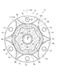
図3に示すように、フランジ12の外形は、円形状を呈している。
フランジ12には、回転軸O1方向に貫通するボルト穴13が周方向に等間隔で6つ形成されている。フランジ12の後面であってボルト穴13の周辺には、座面14が形成されている。座面14は、ボルトBの頭部に締結される部位であり、切削等により平坦に形成されている。
本体部11の内周面は、球面状に形成されている。本体部11の内周面には、前後に延在し断面視で円弧状の外溝11bが周方向に複数形成されている。
フランジ12は、変速機の出力軸に連結するコンパニオンフランジ80(図4参照)と連結するための部位であり、本体部11の外周面11aの前端に位置している。
図3に示すように、フランジ12の外形は、円形状を呈している。
フランジ12には、回転軸O1方向に貫通するボルト穴13が周方向に等間隔で6つ形成されている。フランジ12の後面であってボルト穴13の周辺には、座面14が形成されている。座面14は、ボルトBの頭部に締結される部位であり、切削等により平坦に形成されている。
図2に示すように、内輪20は円筒状を呈しており、内輪20の内周面に穴スプライン21が形成されている。内輪20の外周面は、球面状に形成されている。また、内輪20の外周面には、前後方向に延在し断面視で円弧状の内溝22が周方向に複数形成されている。内輪20の外周面にはケージ23が嵌め込まれている。ケージ23には、開口である窓部24が形成されている。
ボール30は、金属製の球体である。ボール30は、内輪20の内溝22内に収容されつつ一部がケージ23の窓部24から露出している。また、ボール30において窓部24から外側に露出する部分は、外輪10の外溝11bに入り込んでいる。
ケージ23は、内輪20の内溝22と、外輪10の外溝11bとの間で転動するボール30が、入力軸となる外輪10と、出力軸となる内輪20とのなす角度の二等分線上に配置されるような働きをする。この働きにより入力軸と出力軸は回転変動を生じることなく動力が伝達される。
ケージ23は、内輪20の内溝22と、外輪10の外溝11bとの間で転動するボール30が、入力軸となる外輪10と、出力軸となる内輪20とのなす角度の二等分線上に配置されるような働きをする。この働きにより入力軸と出力軸は回転変動を生じることなく動力が伝達される。
スタブシャフト40は、回転軸O1方向に延在する軸部材であり、前部に配置された小径部41と、後部に配置された大径部42と、小径部41と大径部42との間に介在する中間部43と、を備えている。
小径部41の外周面には、軸スプライン41aが形成されており、この軸スプライン41aと内輪20の穴スプライン21とがスプライン嵌合している。
大径部42の外周面42cは、円形状を呈し(図3の仮想線参照)、外径が第1パイプ2と同径に形成されている。大径部42の後端部42aは、第1パイプ2の前端に接合し、大径部42の後端面に肉抜き穴42bが形成されている。
小径部41の外周面には、軸スプライン41aが形成されており、この軸スプライン41aと内輪20の穴スプライン21とがスプライン嵌合している。
大径部42の外周面42cは、円形状を呈し(図3の仮想線参照)、外径が第1パイプ2と同径に形成されている。大径部42の後端部42aは、第1パイプ2の前端に接合し、大径部42の後端面に肉抜き穴42bが形成されている。
図3に示すように、大径部42の前端部44の外周面には、径方向内側に凹む6つの円弧面45が形成されている。このため、大径部42の前端部44であって円弧面45の外周側には、大径部42の他の部位の外周面42cよりも径方向に窪む逃げ部(空間)46が形成されている。
また、円弧面45は、回転軸O1とボルト穴13の中心O2とを結ぶ線の延長線L上であって、ボルト穴13よりも径方向外側に位置する点O3を中心としている。よって、回転軸O1方向から視ると、各ボルト穴13の径方向内側に、円弧面45と逃げ部46が配置されている。
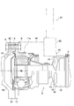
また、図2に示すように、大径部42の外径は、外輪10の本体部11の外径よりも小径に形成されている(図2の補助線M参照)。このため、円弧面45及び逃げ部46は、本体部11の外周面11aよりも径方向内側に位置している。
また、円弧面45は、回転軸O1とボルト穴13の中心O2とを結ぶ線の延長線L上であって、ボルト穴13よりも径方向外側に位置する点O3を中心としている。よって、回転軸O1方向から視ると、各ボルト穴13の径方向内側に、円弧面45と逃げ部46が配置されている。
また、図2に示すように、大径部42の外径は、外輪10の本体部11の外径よりも小径に形成されている(図2の補助線M参照)。このため、円弧面45及び逃げ部46は、本体部11の外周面11aよりも径方向内側に位置している。
中間部43は、小径部41と略同径に形成されており、外周面にバンド53により締め付けられたブーツ50の後端51が取り付けられている。
ブーツ50は、外輪10の後開口を閉塞するゴム製の部品であり、断面視で略J字状となっている。
ブーツアダプタ60は、円筒状を呈する金属製の部品であり、前端61が外輪10の外周面11aに嵌め込まれるとともに加締められている。ブーツアダプタ60の後端62は、内側に折り返されてブーツ50の前端52を挟持している。
ブーツ50は、外輪10の後開口を閉塞するゴム製の部品であり、断面視で略J字状となっている。
ブーツアダプタ60は、円筒状を呈する金属製の部品であり、前端61が外輪10の外周面11aに嵌め込まれるとともに加締められている。ブーツアダプタ60の後端62は、内側に折り返されてブーツ50の前端52を挟持している。
つぎに、推進軸1の取り付け作業を説明する。
図4に示すように、外輪10のフランジ12とコンパニオンフランジ80のフランジ81とを突き合わせ、互いのボルト穴13,82が重なるように配置する。次に、ボルトBをボルト穴13の後方から挿通し、ナットNと螺合させる。また、ボルトBを回転させてフランジ12とフランジ81を締結する。
図4に示すように、外輪10のフランジ12とコンパニオンフランジ80のフランジ81とを突き合わせ、互いのボルト穴13,82が重なるように配置する。次に、ボルトBをボルト穴13の後方から挿通し、ナットNと螺合させる。また、ボルトBを回転させてフランジ12とフランジ81を締結する。
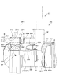
各ボルト穴13にボルトBを挿通し締結したら、次にボルトB及びナットNの締め付けトルクを所定値に設定する。ここで、ボルト締結工具91を直接ボルトBの頭部に係合させようとすると、ボルト締結工具91の係合部92が外輪10の外周面11aに干渉し係合できない。よって、ボルトBの頭部にエクステンション90の前端を嵌め、エクステンション90の後端にボルト締結工具91を係合させる。これによれば、ボルト締結工具91の係合部92の一部は、大径部42の逃げ部46内に配置される(図4、図5参照)。
次に、図示しない工具をナットNに係止させて回転しないように保持しつつ、ボルト締結工具91をボルト穴13の中心O2回りに回動し、締め付けトルクを所定値に設定する。各ボルトBの締め付けトルクが所定値に設定されたら、取り付け作業が終了する。
以上、第1実施形態によれば、エクステンション90を用いてボルトBを締め付ける際、ボルト締結工具91が大径部42と干渉しないため、ボルトBの締め付け作業が容易となる。また、ボルト締結工具91による締め付け作業中に、非円形となっている大径部42の前端部44に工具を係止させて推進軸1が回転しないようにでき、取り付けの作業性が向上する。また、スタブシャフト40が長尺化していないため、コストの増大化も回避できる。
(第2実施形態)
次に第2実施形態の推進軸101について説明する。
推進軸101は、第1パイプ2と、第2パイプ3と、中間自在継手4と、前側自在継手106と、後側自在継手7と、を備えている。前側自在継手106は、外輪10と、内輪20と、複数のボール30と、スタブシャフト140と、ブーツ50と、ブーツアダプタ60と、を備えている。よって、推進軸101は、スタブシャフト40に代えてスタブシャフト140を備えている点が第1実施形態の推進軸1との相違点である。以下、相違点に絞って説明する。
次に第2実施形態の推進軸101について説明する。
推進軸101は、第1パイプ2と、第2パイプ3と、中間自在継手4と、前側自在継手106と、後側自在継手7と、を備えている。前側自在継手106は、外輪10と、内輪20と、複数のボール30と、スタブシャフト140と、ブーツ50と、ブーツアダプタ60と、を備えている。よって、推進軸101は、スタブシャフト40に代えてスタブシャフト140を備えている点が第1実施形態の推進軸1との相違点である。以下、相違点に絞って説明する。
図6に示すように、スタブシャフト140の大径部142の外周面142cは、円形状を呈している(図6の破線参照)。大径部142の外径は、r1に設定され、第2パイプ3と同径となっている。
大径部142の前端部144の外周面145は、半径がr2となっており、外周面142cよりも小さい円形状となっている。このため、外周面145の外周側には、外周面142cよりも径方向内側に窪む環状の逃げ部(空間)146が形成されている。
大径部142の前端部144の外周面145は、半径がr2となっており、外周面142cよりも小さい円形状となっている。このため、外周面145の外周側には、外周面142cよりも径方向内側に窪む環状の逃げ部(空間)146が形成されている。
以上、第2実施形態によれば、エクステンション90を用いてボルトBを締め付ける際、ボルト締結工具91の係合部92の一部が逃げ部146に配置され、前端部144の外周面145と干渉しない。よって、ボルトBの締め付け作業が容易となる。
(第3実施形態)
次に第3実施形態の推進軸201について説明する。
推進軸201は、第1パイプ2と、第2パイプ3と、中間自在継手4と、前側自在継手206と、後側自在継手7と、を備えている。
図7に示すように、前側自在継手206は、クロスクローブ型の等速ジョイントであり、外輪210と、内輪220と、複数のボール(不図示)と、スタブシャフト240と、ブーツ250と、ブーツアダプタ260と、を備えている。
次に第3実施形態の推進軸201について説明する。
推進軸201は、第1パイプ2と、第2パイプ3と、中間自在継手4と、前側自在継手206と、後側自在継手7と、を備えている。
図7に示すように、前側自在継手206は、クロスクローブ型の等速ジョイントであり、外輪210と、内輪220と、複数のボール(不図示)と、スタブシャフト240と、ブーツ250と、ブーツアダプタ260と、を備えている。
外輪210は、前後に開口する円筒状の本体部211により構成されている。本体部211には、前端面と後端面とを貫通するボルト穴213が周方向に複数形成されている。
内輪220の内周面には、穴スプライン221が形成されている。内輪220の外周面には、ケージ223が嵌め込まれている。
ボールは、内輪220の内溝(不図示)内に収容されつつ一部がケージ223の窓部(不図示)から露出している。また、ボールにおいて窓部から外側に露出する部分は、外輪210の外溝(不図示)に入り込んでいる。
ケージ223は、内輪220の内溝と、外輪210の外溝(不図示)との間で摺動するボールが、入力軸となる外輪210と、出力軸となる内輪220とのなす角度の二等分線上に配置されるような働きをする。この働きにより入力軸と出力軸は回転変動を生じることなく動力が伝達される。
内輪220の内周面には、穴スプライン221が形成されている。内輪220の外周面には、ケージ223が嵌め込まれている。
ボールは、内輪220の内溝(不図示)内に収容されつつ一部がケージ223の窓部(不図示)から露出している。また、ボールにおいて窓部から外側に露出する部分は、外輪210の外溝(不図示)に入り込んでいる。
ケージ223は、内輪220の内溝と、外輪210の外溝(不図示)との間で摺動するボールが、入力軸となる外輪210と、出力軸となる内輪220とのなす角度の二等分線上に配置されるような働きをする。この働きにより入力軸と出力軸は回転変動を生じることなく動力が伝達される。
スタブシャフト240は、前部に配置された小径部241と、後部に配置された大径部242と、小径部241と大径部242との間に介在する中間部243と、を備えている。
小径部241の外周面には、軸スプライン241aが形成されており、この軸スプライン241aと内輪220の穴スプライン221とがスプライン嵌合している。
大径部242の外周面242cは円形状を呈し、大径部142の外径が第2パイプ3と同径となっている。
大径部242の前端部244の外周面245は、外周面242cよりも小径に形成され、円形状となっている。このため、外周面245の外周側には、環状の逃げ部(空間)246が形成されている。
また、前端部244の外径は、ブーツアダプタ260の後述する円筒部263の外径よりも小さい(図7の補助線Pを参照)。
小径部241の外周面には、軸スプライン241aが形成されており、この軸スプライン241aと内輪220の穴スプライン221とがスプライン嵌合している。
大径部242の外周面242cは円形状を呈し、大径部142の外径が第2パイプ3と同径となっている。
大径部242の前端部244の外周面245は、外周面242cよりも小径に形成され、円形状となっている。このため、外周面245の外周側には、環状の逃げ部(空間)246が形成されている。
また、前端部244の外径は、ブーツアダプタ260の後述する円筒部263の外径よりも小さい(図7の補助線Pを参照)。
ブーツ250の後端は、バンド253により、スタブシャフト240の中間部243に取り付けられている。
ブーツアダプタ260は、外輪210の本体部211の外周面211aに外嵌される外嵌部261と、外嵌部261の後端から径方向内側に折り返された折り返し部262と、折り返し部262の内端から後方に延在する円筒部263と、円筒部263の後端を径方向内側に折り返してブーツ250の前端を挟持する挟持部264と、を備えている。
なお、ボルト穴213に挿入され本体部211を締結するボルトBは、頭部の外周面と円筒部263との隙間が小さいことから、頭部に六角形状の穴B1が形成されたものが用いられている。また、本体部211とボルトBの頭部の間には、ワッシャWが介在している。
ブーツアダプタ260は、外輪210の本体部211の外周面211aに外嵌される外嵌部261と、外嵌部261の後端から径方向内側に折り返された折り返し部262と、折り返し部262の内端から後方に延在する円筒部263と、円筒部263の後端を径方向内側に折り返してブーツ250の前端を挟持する挟持部264と、を備えている。
なお、ボルト穴213に挿入され本体部211を締結するボルトBは、頭部の外周面と円筒部263との隙間が小さいことから、頭部に六角形状の穴B1が形成されたものが用いられている。また、本体部211とボルトBの頭部の間には、ワッシャWが介在している。
以上、第3実施形態によれば、エクステンション90の先端部に形成された六角軸90aをボルトBの六角形状の穴B1内に挿入し、エクステンション90の後端にボルト締結工具91の係合部92を係合させると、係合部92の一部が逃げ部246に配置され前端部244の外周面245に干渉しない。よって、ボルトBの締め付け作業が容易となる。
以上、各実施形態について説明したが、本発明は、実施形態で説明した例に限定されない。
大径部の外周側に複数の逃げ部を形成するため、第1実施形態では、大径部42の前端部44に複数の円弧面45を形成しているが、本発明は、大径部の前端部の外周面を軸方向から視て多角形状に形成することで、外周側に逃げ部が形成されるようにしてもよい。
大径部の外周側に複数の逃げ部を形成するため、第1実施形態では、大径部42の前端部44に複数の円弧面45を形成しているが、本発明は、大径部の前端部の外周面を軸方向から視て多角形状に形成することで、外周側に逃げ部が形成されるようにしてもよい。
また、前側自在継手と後側自在継手として、バーフィールド型とクロスクローブ型の等速ジョイントを挙げたが、トリポード型やダブルオフセット型の等速ジョイントであってもよい。また、トリポード型やダブルオフセット型の等速ジョイントを用いる場合にあっては、逃げ部の少なくとも一部が外輪の本体部の外周面よりも径方向内側に位置するように形成する必要がある。
また、各実施形態において、大径部の前端部の外周側にのみ逃げ部が形成されるように構成されているが、本発明は、大径部の前後方向の中間部の外周側や、後端部の外周側に逃げ部を拡張してよい。
なお、大径部の中間部や後端部に逃げ部を拡張すると、大径部の外径が小さくなり、所定の強度を有しないおそれがある。よって、このような場合には、大径部における肉抜き穴の内周面を径方向内側に膨出させて所定の肉厚を確保する方法が挙げられる。
また、図8に示すように、大径部342の内周面342aを膨出させる場合、スタブシャフトの偏芯を抑制するため、肉抜き穴342bの内周面342aを、円弧面345が形成された前端部344の外周面346と相似形にすることが好ましい。
なお、大径部の中間部や後端部に逃げ部を拡張すると、大径部の外径が小さくなり、所定の強度を有しないおそれがある。よって、このような場合には、大径部における肉抜き穴の内周面を径方向内側に膨出させて所定の肉厚を確保する方法が挙げられる。
また、図8に示すように、大径部342の内周面342aを膨出させる場合、スタブシャフトの偏芯を抑制するため、肉抜き穴342bの内周面342aを、円弧面345が形成された前端部344の外周面346と相似形にすることが好ましい。
1,101,201 推進軸
6,106,206 前側自在継手
10,210 外輪
11,211 本体部
12 フランジ
13,213 ボルト穴
20,220 内輪
40,140,240 スタブシャフト(軸部材)
41,241 小径部
42,142,242,442 大径部
42c,142c,242c 外周面
44,144,244 前端部
45,445 円弧面
46,146,246 逃げ部
50,250 ブーツ
60,260 ブーツアダプタ
80 コンパニオンフランジ
81 フランジ
90 エクステンション
91 ボルト締結工具
92 係合部
145,245,346 外周面
263 円筒部
6,106,206 前側自在継手
10,210 外輪
11,211 本体部
12 フランジ
13,213 ボルト穴
20,220 内輪
40,140,240 スタブシャフト(軸部材)
41,241 小径部
42,142,242,442 大径部
42c,142c,242c 外周面
44,144,244 前端部
45,445 円弧面
46,146,246 逃げ部
50,250 ブーツ
60,260 ブーツアダプタ
80 コンパニオンフランジ
81 フランジ
90 エクステンション
91 ボルト締結工具
92 係合部
145,245,346 外周面
263 円筒部
Claims (7)
- 自在継手と、前記自在継手に連結する軸部材と、を備える推進軸であって、
前記自在継手は、外輪と、前記軸部材の一端部に連結され前記外輪内に揺動自在に配置された動力伝達部材と、を備え、
前記軸部材は、前記一端部よりも大径に形成された大径部を有し、
前記外輪には、軸方向に貫通する複数のボルト穴が形成され、
前記大径部の一端部には、軸方向から視て前記ボルト穴と同位相に配置され、ボルト締結工具に対する逃げ部が複数形成されていることを特徴とする推進軸。 - 自在継手と、前記自在継手に連結する軸部材と、を備える推進軸であって、
前記自在継手は、外輪と、前記軸部材の一端部に連結され前記外輪内に揺動自在に配置された動力伝達部材と、を備え、
前記軸部材は、前記一端部よりも大径に形成された大径部を有し、
前記外輪には、軸方向に貫通する複数のボルト穴が形成され、
前記大径部の一端部には、ボルト締結工具に対する逃げ部が形成され、
前記逃げ部は、軸心を中心とする環状を成していることを特徴とする推進軸。 - 前記大径部の一端部の外周面は、軸方向から視て多角形状となっていることを特徴とする請求項1に記載の推進軸。
- 前記大径部の一端部の外周面には、前記各ボルト穴と前記軸部材の中心とを結ぶ線の延長線上に中心を持つ円弧面が複数形成されていることを特徴とする請求項1に記載の推進軸。
- 前記大径部は、内部空間を有し、
前記大径部の内周面は、前記一端部の外周面と相似していることを特徴とする請求項3又は請求項4に記載の推進軸。 - 前記外輪の他端側開口を封止するゴム製の封止部材と、
一端部が前記外輪に固定され、他端部が前記封止部材を支持する円筒部材と、を備え、
前記ボルト穴は、前記外輪の本体部に形成され、
前記円筒部材は、前記外輪の本体部よりも小径に形成され、
前記逃げ部の少なくとも一部は、前記円筒部材の外周面よりも径方向内側に位置していることを特徴とする請求項1から請求項4のいずれか1項に記載の推進軸。 - 前記ボルト穴は、前記外輪のフランジに形成され、
前記逃げ部の少なくとも一部は、前記外輪の本体部の外周面よりも径方向内側に位置していることを特徴とする請求項1から請求項4のいずれか1項に記載の推進軸。
Applications Claiming Priority (2)
| Application Number | Priority Date | Filing Date | Title |
|---|---|---|---|
| JP2018-227611 | 2018-12-04 | ||
| JP2018227611 | 2018-12-04 |
Publications (1)
| Publication Number | Publication Date |
|---|---|
| WO2020115917A1 true WO2020115917A1 (ja) | 2020-06-11 |
Family
ID=70974219
Family Applications (1)
| Application Number | Title | Priority Date | Filing Date |
|---|---|---|---|
| PCT/JP2018/045601 Ceased WO2020115917A1 (ja) | 2018-12-04 | 2018-12-12 | 推進軸 |
Country Status (1)
| Country | Link |
|---|---|
| WO (1) | WO2020115917A1 (ja) |
Citations (5)
| Publication number | Priority date | Publication date | Assignee | Title |
|---|---|---|---|---|
| JPS6014980Y2 (ja) * | 1980-03-25 | 1985-05-13 | 日産自動車株式会社 | Frp製プロペラシヤフト |
| JP2014231869A (ja) * | 2013-05-29 | 2014-12-11 | 日立オートモティブシステムズ九州株式会社 | プロペラシャフト及びプロペラシャフトに用いられる自在継手のヨーク構造 |
| JP2017095035A (ja) * | 2015-11-27 | 2017-06-01 | 株式会社ショーワ | 車両用推進軸 |
| JP2018105328A (ja) * | 2016-12-22 | 2018-07-05 | Ntn株式会社 | 摺動式等速自在継手 |
| WO2018132153A2 (en) * | 2016-11-01 | 2018-07-19 | Dana Automotive Systems Group, Llc | A coupling assembly having angled fastener holes |
-
2018
- 2018-12-12 WO PCT/JP2018/045601 patent/WO2020115917A1/ja not_active Ceased
Patent Citations (5)
| Publication number | Priority date | Publication date | Assignee | Title |
|---|---|---|---|---|
| JPS6014980Y2 (ja) * | 1980-03-25 | 1985-05-13 | 日産自動車株式会社 | Frp製プロペラシヤフト |
| JP2014231869A (ja) * | 2013-05-29 | 2014-12-11 | 日立オートモティブシステムズ九州株式会社 | プロペラシャフト及びプロペラシャフトに用いられる自在継手のヨーク構造 |
| JP2017095035A (ja) * | 2015-11-27 | 2017-06-01 | 株式会社ショーワ | 車両用推進軸 |
| WO2018132153A2 (en) * | 2016-11-01 | 2018-07-19 | Dana Automotive Systems Group, Llc | A coupling assembly having angled fastener holes |
| JP2018105328A (ja) * | 2016-12-22 | 2018-07-05 | Ntn株式会社 | 摺動式等速自在継手 |
Similar Documents
| Publication | Publication Date | Title |
|---|---|---|
| JPWO2019054167A1 (ja) | 動力伝達軸 | |
| US6976922B2 (en) | Precision thrust bearing joint | |
| JP6533860B1 (ja) | 推進軸 | |
| US20160108968A1 (en) | Stopper piece and bearing apparatus | |
| CA2933142A1 (en) | Joint yoke for a universal joint and universal joint | |
| JP2011190880A (ja) | 動力伝達装置 | |
| WO2016013192A1 (ja) | 連結部材およびその連結部材を含む連結構造 | |
| JP5016528B2 (ja) | プロペラシャフト | |
| US9017175B2 (en) | Propshaft assembly | |
| JP5867121B2 (ja) | 車輪支持装置 | |
| JP2010078010A (ja) | 動力伝達用ドライブプレート | |
| JP2001213179A (ja) | ハイブリッド車両の自動変速機取り付け構造 | |
| JPWO2017033571A1 (ja) | 動力伝達装置 | |
| US11242897B2 (en) | Coupling assembly having angled fastener holes | |
| JP2002337504A (ja) | 車輪駆動用軸受ユニットの組立方法及び組立用治具 | |
| KR102119259B1 (ko) | 휠 베어링 조립체 | |
| JP2019038466A (ja) | 推進軸 | |
| US20180363711A1 (en) | Wheel drive unit for vehicle | |
| JP2019027570A (ja) | 推進軸 | |
| JP2013253645A (ja) | 等速ジョイントの取り付け構造およびプロペラシャフト | |
| JP2008286359A (ja) | クランク軸ボルト締結構造 | |
| JP2014020434A (ja) | 等速自在継手 | |
| JPH1178563A (ja) | プロペラシャフトの衝撃吸収構造 | |
| JP2007292123A (ja) | デファレンシャルとドライブシャフトとの連結構造 | |
| JP7147509B2 (ja) | トルク伝達軸 |
Legal Events
| Date | Code | Title | Description |
|---|---|---|---|
| 121 | Ep: the epo has been informed by wipo that ep was designated in this application |
Ref document number: 18942416 Country of ref document: EP Kind code of ref document: A1 |
|
| NENP | Non-entry into the national phase |
Ref country code: DE |
|
| 122 | Ep: pct application non-entry in european phase |
Ref document number: 18942416 Country of ref document: EP Kind code of ref document: A1 |