WO2020111175A1 - 中空糸膜エレメント及びその製造方法 - Google Patents
中空糸膜エレメント及びその製造方法 Download PDFInfo
- Publication number
- WO2020111175A1 WO2020111175A1 PCT/JP2019/046544 JP2019046544W WO2020111175A1 WO 2020111175 A1 WO2020111175 A1 WO 2020111175A1 JP 2019046544 W JP2019046544 W JP 2019046544W WO 2020111175 A1 WO2020111175 A1 WO 2020111175A1
- Authority
- WO
- WIPO (PCT)
- Prior art keywords
- hollow fiber
- water collecting
- fiber membrane
- tubular
- protrusion
- Prior art date
- Legal status (The legal status is an assumption and is not a legal conclusion. Google has not performed a legal analysis and makes no representation as to the accuracy of the status listed.)
- Ceased
Links
Images


Classifications
-
- B—PERFORMING OPERATIONS; TRANSPORTING
- B01—PHYSICAL OR CHEMICAL PROCESSES OR APPARATUS IN GENERAL
- B01D—SEPARATION
- B01D63/00—Apparatus in general for separation processes using semi-permeable membranes
Definitions
- the present invention relates to a hollow fiber membrane element and a method for producing the same.
- the present application claims priority based on Japanese Patent Application No. 2018-222747 filed in Japan on November 28, 2018, and the content thereof is incorporated herein.
- Hollow fiber membrane elements are widely used in the production of sterile water, drinking water, and high-purity water.
- the hollow fiber membrane element for example, one in which water collecting pipes are provided at both ends in the length direction of the hollow fiber membrane, and tubular struts that are connected in communication with the water collecting pipe are known (Patent Reference 1).
- tubular projections communicating with the water collecting portion are provided at both ends of the water collecting pipe so as to be fitted and connected to the ends of the tubular support.
- resin is injected around the projection, the end of the tubular support is inserted into the end of the water collection pipe, and then the resin is cured. Since the gap between the protrusion and the tubular strut is filled with resin, a hollow fiber membrane element having excellent water tightness at the connecting portion between the ends of the water collecting pipe and the tubular strut can be obtained.
- the connection portion between the protrusion and the end portions of the tubular support is sufficiently water-tightly sealed with the resin. It is necessary to divide the resin injection and curing into multiple times. Specifically, after adjusting the amount of resin so that the resin surface injected into the water collection tube does not exceed the height of the protrusion, after inserting the tubular support and once hardening the resin, a sufficient amount of resin is obtained. Resin is further injected so as to be cured.
- An object of the present invention is to provide a hollow fiber membrane element having tubular struts on both sides in the width direction of a hollow fiber membrane sheet-like article, which has high production efficiency and excellent productivity, and a production method thereof.
- the protrusion is provided as a standard for the fixing position when fixing the tubular support to the water collecting pipe. Therefore, it has been considered that a lower protrusion is preferable so that the tubular support can be easily installed in the water collection pipe.
- the present inventors have completed the present invention by finding that the manufacturing efficiency is increased by increasing the height of the protrusion, regardless of the conventional purpose of the protrusion.
- the height of the tubular protrusions arranged in the water collection pipe is set to 40% or more of the height of the lowest portion of the peripheral wall portion surrounding the protrusions. As a result, the number of times of injecting and curing the potting material for fixing the water collecting pipe and the tubular support can be reduced, and the manufacturing efficiency can be improved and the productivity can be improved. That is, the present invention has the following configurations.
- a plurality of hollow fiber membranes A first water collecting pipe and a second water collecting pipe respectively provided on the first opening end side and the second opening end side in the length direction of the hollow fiber membrane, Tubular struts whose both ends are connected to the first water collection pipe and the second water collection pipe; Equipped with The first opening end portion and the second opening end portion of the hollow fiber membrane are respectively inserted into the first water collecting pipe and the second water collecting pipe in a state where the end faces of the respective hollow fiber membranes are open, At least one of the first water collecting pipe, the second water collecting pipe, and the tubular support is formed with at least one outlet for taking out treated water, The first water collecting pipe and the second water collecting pipe are provided with tubular protrusions that are connected to the water collecting portions inside the first water collecting pipe and the second water collecting pipe and are connected to the tubular support columns.
- a peripheral wall portion surrounding the protrusion is provided,
- the protrusion is located within the end of the tubular strut,
- the height of the protrusion is 40% or more of the height of the lowest portion of the peripheral wall portion,
- the inside of the tubular column and the water collecting portion inside the first water collecting pipe and the second water collecting pipe communicate with each other through the inside of the protrusion.
- Hollow fiber membrane element [2] The hollow fiber membrane element according to [1], wherein the tubular support and the first water collecting pipe and the second water collecting pipe are fixed in a watertightly sealed state.
- the gap between the tubular column and the protrusion at an insertion portion where the protrusion is inserted into the end of the tubular column is fixed in a watertight manner with a potting material, [1] or [ The hollow fiber membrane element according to 2].
- the protrusion is composed of a tubular protrusion communicating with the water collecting portion inside the first water collecting pipe and the second water collecting pipe, and a tubular sleeve connected to the protrusion.
- the hollow fiber membrane element according to any one of 1] to [3].
- [5] The hollow fiber membrane element according to [4], wherein a part of the tubular sleeve on the side of the protrusion is inserted inside the protrusion.
- the hollow fiber membrane element according to any one of [1] to [11], which is provided with a second closing portion.
- a plurality of hollow fiber membranes A first water collecting pipe and a second water collecting pipe respectively provided on the first opening end side and the second opening end side of the hollow fiber membrane in the length direction of the hollow fiber membrane, Tubular struts whose both ends are connected to the first water collection pipe and the second water collection pipe; Equipped with The first opening end portion and the second opening end portion of the hollow fiber membrane are respectively inserted into the first water collecting pipe and the second water collecting pipe in a state where the end faces of the respective hollow fiber membranes are open, The inside of the tubular column and the water collecting portion inside the first water collecting pipe and the second water collecting pipe communicate with each other, The tubular support and the first water collecting pipe and the second water collecting pipe are fixed in a watertightly sealed state, The outer surface of the end of the tubular strut is blasted, Hollow fiber membrane element.
- a hollow fiber membrane element having tubular struts on both sides in the width direction of a hollow fiber membrane sheet-like article, which has high manufacturing efficiency and excellent productivity, and a manufacturing method thereof.
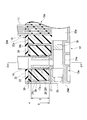
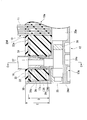
- FIG. 3 is a sectional view taken along the line AA of the hollow fiber membrane element of FIG. 2. It is a BB sectional view of the hollow fiber membrane element of FIG. It is another mode of the hollow fiber membrane element of FIG. It is another mode of the hollow fiber membrane element of FIG. It is a modification of the hollow fiber membrane element of FIG. It is CC sectional drawing of the hollow fiber membrane element of FIG.
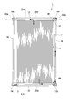
- the hollow fiber membrane element 1 of the present embodiment has a hollow fiber membrane sheet-like material 10, a first water collecting pipe 12, a second water collecting pipe 14, and tubular struts 16 (18). It has and.
- the hollow fiber membrane sheet material 10 is a plurality of hollow fiber membranes 11 bundled into a sheet.
- the first water collecting pipe 12 is provided on the first opening end 10a side of the hollow fiber membrane sheet material 10 in the length direction of the hollow fiber membrane 11.
- the second water collecting pipe 14 is provided on the second opening end 10b side opposite to the first opening end 10a in the length direction of the hollow fiber membrane sheet material 10.
- the tubular support 16 is provided on one side in the width direction of the hollow fiber membrane sheet material 10.
- the first end 17 a of the tubular strut 16 is connected to the first end 13 a of the first water collection pipe 12.
- the second end 17b of the tubular strut 16 is connected to the first end 15a of the second water collection pipe 14.
- the tubular strut 18 is provided on the other side of the hollow fiber membrane sheet-like object 10 in the width direction.
- the first end 19 a of the tubular strut 18 is connected to the second end 13 b of the first water collection pipe 12.
- the second end 19b of the tubular strut 18 is connected to the second end 15b of the second water collection pipe 14.
- the hollow fiber membrane element 1 is arranged such that the first water collection pipe 12 is on the lower side and the second water collection pipe 14 is on the upper side, and the length direction of each hollow fiber membrane 11 of the hollow fiber membrane sheet-shaped article 10 is the vertical direction. Has been done.
- the hollow fiber membrane sheet-like article 10 is formed by bundling a plurality of hollow fiber membranes 11 in parallel with each other in a sheet form.
- the number of the hollow fiber membranes 11 in the hollow fiber membrane sheet material 10 is not particularly limited and can be, for example, 1000 to 2000.
- the hollow fiber membrane sheet material 10 of this example is a laminated body in which a plurality of sheets in which a plurality of hollow fiber membranes 11 are aligned are laminated.
- the hollow fiber membrane sheet material may be a laminated body of such a plurality of sheets or may be a single sheet.
- the material of the hollow fiber membrane examples include polysulfone-based resin, polyacrylonitrile, cellulose derivative, polyolefin such as polyethylene and polypropylene, fluorine-based resin such as polyvinylidene fluoride (PVDF) and polytetrafluoroethylene, polyamide, polyester, polymethacrylate. , Polyacrylate and the like. Moreover, you may use what introduce
- the material of the hollow fiber membrane may be one kind or two or more kinds.
- a plurality of hollow fiber membranes 11 may be used to form and use the hollow fiber membrane sheet according to the method for producing a hollow fiber membrane sheet described in Japanese Patent No. 5919672.
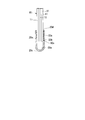
- the first water collecting pipe 12 has an opening 20d extending in the longitudinal direction between the first end 13a and the second end 13b, and the first opening of the hollow fiber membrane sheet material 10 is formed in the opening 20d.
- the end portion 10a is adapted to be inserted.
- the portion between the first end portion 13a and the second end portion 13b in the first water collection pipe 12 of this example has a pair of long elongate surfaces facing each other as shown in FIG. It is provided with side wall portions 20a and 20b.
- a portion between the first end portion 13a and the second end portion 13b in the first water collection pipe 12 of this example includes a bottom portion 20c having a semicircular cross section that connects one end portions of the side wall portions 20a and 20b. ..
- a slit-shaped opening 20d extending in the longitudinal direction is formed on the side of the first water collection pipe 12 opposite to the bottom 20c.
- the cross section of the first water collection pipe 12 that is orthogonal to the longitudinal direction is U-shaped.
- the first opening end 10a of the hollow fiber membrane sheet 10 is inserted into the opening 20d of the first water collecting pipe 12 with each end of the hollow fiber membrane 11 open.
- the first open end portion 10a of the hollow fiber membrane sheet material 10 is a potting portion 22a made of a cured material of the potting material with the end surface of each hollow fiber membrane 11 open. It is fixed.
- the bottom portion 20c side of the potting portion 22a in the first water collecting pipe 12 serves as a water collecting portion 20e.
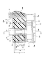
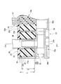
- the first end portion 13a of the first water collection pipe 12 includes a tubular portion 24a that communicates with the water collection portion 20e.
- the first end portion 13a of the first water collection pipe 12 is provided with a tubular protrusion 29 positioned so as to project toward the opening 20d side of the first water collection pipe 12.
- the first end portion 13 a of the first water collection pipe 12 includes a peripheral wall portion 24 c positioned so as to surround four sides of the protrusion 29.
- the peripheral wall portion 24c is for blocking the potting material 30 so as not to leak from the opening 20d of the first water collection pipe 12 when fixing the tubular support 16.
- the potting material 30 is supplied around the insertion portion where the tubular support 16 is inserted into the protrusion 29 and the protrusion 29 is inserted into the first end portion 17 a of the tubular support 16.
- Two of the four peripheral wall portions 24c surrounding the four sides of the protrusion 29 are provided on both sides of the protrusion 29 on the tubular portion 24a in the longitudinal direction of the water collecting pipe so as to be spaced apart from the protrusion 29 and face each other. ..
- the remaining two of the four peripheral wall portions 24c are provided on both sides of the projection 29 on the tubular portion 24a in the lateral direction of the water collecting pipe so as to be spaced apart from the projection 29 and to face each other, and the side wall portions 20a, respectively. , 20b and a continuous wall.
- the upper end on the center side in the longitudinal direction of the first water collection pipe 12 is slightly lower than the upper ends of the side wall portions 20a and 20b.
- the upper end of the first water collecting pipe 12 on the center side in the longitudinal direction is a peripheral wall portion 24c on the side closer to the first opening end portion 10a of the hollow fiber membrane sheet material 10.
- the remaining three peripheral wall portions 24c that is, the upper end of the peripheral wall portion 24c on the end face side of the first water collection pipe 12 and the pair of peripheral wall portions 24c facing each other in the lateral direction have the same height as the upper ends of the side wall portions 20a, 20b. It has become.
- a modified example of the peripheral wall portion 24c is one in which the peripheral wall portion 24c on the side closer to the first opening end portion 10a of the hollow fiber membrane sheet-like article 10 is not present, as shown in FIG.
- the peripheral wall portion 24c on the end face side of the first end portion 13a and the second end portion 13b of the first water collection pipe 12 and the side wall portions 20a and 20b are an integral continuous wall.
- the potting material 30 can be dammed so as not to leak from the opening 20d of the first water collection pipe 12.
- the potting material 30 is supplied around the insertion portion where the tubular support 16 is inserted into the protrusion 29 and the protrusion 29 is inserted into the first end portion 17 a of the tubular support 16.
- the tubular projection 29 located at the first end 13a of the first water collection pipe 12 is a portion for connecting with the tubular support 16.
- the inside of the protrusion 29 communicates with the inside of the tubular portion 24a.
- the shape of the protrusion 29 is not particularly limited, and examples thereof include a square tube shape and a cylindrical shape.
- the height D of the protrusion 29 is 40% or more of the height E of the lowest portion of the peripheral wall portion 24c, preferably 55% or more, more preferably 70% or more, and further preferably 90% or more.
- the upper limit of the height D of the protrusion 29 is not particularly limited, but the height D of the protrusion 29 is preferably 150% or less, more preferably 130% or less, and 110% or less of the height of the lowest portion of the peripheral wall portion 24c. More preferable.
- the height D of the protrusion 29 is the height from the lower end of the tubular support 16 when the tubular support 16 is inserted into the protrusion 29 to the upper end of the protrusion 29.
- the height E of the lowest portion of the peripheral wall portion 24c is the vertical distance from the lower end of the height D of the protrusion 29 to the upper surface of the lowest portion.
- the lowest portion of the peripheral wall portion 24c is arranged so that the volume of the liquid that can be retained inside the portion surrounded by the peripheral wall portion of the water collecting pipe is maximized when the liquid is poured into the water collecting pipe. This is where the liquid overflows.
- the protrusion and the tubular support are bonded to each other, so that an element structure having high rigidity at the time of completion can be easily formed by one potting.
- the height D of the protrusion 29 is less than or equal to the upper limit of the above range, the water collecting pipe and the tubular sleeve are easily formed, and the portion not bonded to the tubular support is reduced, so that the parts can be effectively used without waste. Due to the presence of the protrusion, the adhesive area between the tubular column and the protrusion is increased, and the adhesive strength is increased.
- the protrusion is formed integrally with the water collection pipe. As a result, the process can be shortened, which has the effect of reducing labor, manufacturing time, investment, and consumables.
- the aspect of the second end portion 13b of the first water collecting pipe 12 is the same aspect as the first end portion 13a, and is provided with a tubular projection 29 for connecting to the tubular support column 18, and the preferred aspect is also the same. ..
- the aspect of the second water collection pipe 14 is the same as that of the first water collection pipe 12, and the preferable aspect is also the same.
- the second open end 10b of the hollow fiber membrane sheet 10 is inserted into the slit-like opening of the second water collection pipe 14, and is fixed by the potting portion with the end surface of each hollow fiber membrane 11 open. ..
- the first end portion 15a and the second end portion 15b of the second water collection pipe 14 are provided with tubular protrusions 29 for connecting to the tubular support column 16 and the tubular support column 18, respectively.
- a tubular protrusion 24b is arranged at the first end 13a of the first water collection pipe 12.
- the protrusion 24b is a portion for connecting with the tubular support 16.
- the inside of the protrusion 24b communicates with the inside of the tubular portion 24a.
- the shape of the protrusion 24b is not particularly limited, and examples thereof include a square tube shape and a cylindrical shape.
- the height of the protrusion 24b is preferably 5 to 30 mm, more preferably 10 to 20 mm. When the height of the protrusion 24b is equal to or higher than the lower limit value of the above range, it is easy to increase the connection strength between the protrusion 24b and the tubular support 16. When the height of the protrusions 24b is not more than the upper limit value of the above range, the moldability is more excellent.
- the height of the protrusion 24b is preferably 50% or less of the height of the peripheral wall 24c. When the height of the protrusion 24b is 50% or less of the height of the peripheral wall 24c, the water collecting pipe and the protrusion have excellent moldability.
- the second end portion 13b of the first water collecting pipe 12 is also provided with a tubular projection portion for connecting to the tubular support column 18.
- the first column 15a and the second end portion 15b of the second water collection pipe 14 are connected to the tubular column 16 (18).
- a tubular projection for The presence of the protrusions is preferable in that the adhesion area between the tubular support and the protrusions is increased and the adhesion strength is improved.
- the protrusion 29 of the first end 13a of the first water collecting pipe 12 is composed of a protrusion 24b and a tubular sleeve 26.
- the tubular sleeve 26 is attached to the protrusion 24 b and is inserted into the first end portion 17 a of the tubular strut 16.
- the first end 17a of the tubular support 16 and the first end 13a of the first water collection pipe 12 are connected.
- the inside of the tubular support 16 and the water collecting portion 20e inside the first water collecting pipe 12 communicate with each other through the inside of the protrusion 29.
- the protrusion of the second end portion 13b of the first water collection pipe 12 is inserted into the first end portion 19a of the tubular column 18 with the tubular sleeve attached to the protrusion.
- the inside of the tubular strut 18 and the water collecting portion 20e inside the first water collecting pipe 12 communicate with each other through the inside of the protrusion.
- the first end 19a of the tubular strut 18 and the second end 13b of the first water collection pipe 12 are connected.
- the protrusion of the first end portion 15a of the second water collecting pipe 14 is inserted into the second end portion 17b of the tubular support 16 with the tubular sleeve attached to the protrusion portion.
- the inside of the tubular support 16 and the water collecting portion 20f inside the second water collecting pipe 14 communicate with each other through the inside of the protrusion.
- the second end 17b of the tubular support 16 and the first end 15a of the second water collection pipe 14 are connected.
- the protrusion of the second end portion 15b of the second water collecting pipe 14 is inserted into the second end portion 19b of the tubular support 18 with the tubular sleeve attached to the protrusion.
- the inside of the tubular support 18 and the water collecting portion 20f inside the second water collecting pipe 14 communicate with each other through the inside of the protrusion.
- the second end 19b of the tubular strut 18 and the second end 15b of the second water collection pipe 14 are connected.
- the protrusion may be composed of a tubular sleeve connected to an opening provided in the first water collection pipe and the second water collection pipe.
- the adhesive can be applied to the horizontal surface of the water collecting pipe when the adhesive for bonding the tubular sleeve to the water collecting pipe is applied.
- the length of the tubular sleeve is preferably 10% or more longer than the height of the protrusion. This is because of the adhesive margin that secures the tubular sleeve to the water collection tube. The presence of the bonding margin increases the bonding area, increases the strength of the hollow fiber membrane element, and facilitates the positioning of the tubular sleeve.
- At least one of the first water collection pipe 12, the second water collection pipe 14, and the tubular support 16 (18) is formed with an outlet for taking out the treated water.
- the outlet is preferably formed on at least one end surface of the first water collection pipe 12 and the second water collection pipe 14.
- the opening 24d of the tubular portion 24a is closed by the lid member 25.
- the opening on the end surface of the water collecting pipe may be used as an outlet for taking out the treated water without closing it with the lid member.
- the material of the water collection pipe is preferably one that has excellent mechanical strength and durability.
- Examples thereof include polycarbonate, polysulfone, polyolefin, PVC (polyvinyl chloride), acrylic resin, ABS resin, and modified PPE (polyphenylene ether).
- the material of the water collecting pipe may be one kind or two or more kinds.
- the form of the tubular support is not particularly limited, and examples thereof include a square tubular shape and a cylindrical shape.
- the material of the tubular support is not particularly limited, and examples thereof include stainless steel (SUS) and the like.
- Examples of the potting material for forming the potting portion include epoxy resins, unsaturated polyester resins, polyurethane resins, resins such as silicone-based fillers and various hot melt resins, and hydraulic cements such as Portland cement and mixed cement. Is mentioned.
- the potting material may be one kind or two or more kinds.
- the protrusion 29 disposed on the first end 13a of the first water collection pipe 12 is in a state in which the tubular sleeve 26 is attached to the protrusion 24b, and the protrusion 29 is The insertion portion 28 inserted in the first end portion 17a of the tubular strut 16 will be described in more detail.
- the protrusion provided on the second end 13b of the first water collection pipe 12 is in a state in which a tubular sleeve is attached to the protrusion.
- the protrusion provided on the first end 15a of the second water collection pipe 14 is in a state in which the tubular sleeve is attached to the protrusion.
- the protrusion provided on the second end portion 15b of the second water collection pipe 14 is in a state in which the tubular sleeve is attached to the protrusion.
- the insertion portion in which the protrusion is inserted has the same aspect as the insertion portion 28 described below, and the preferred aspect is also the same.
- the shape of the tubular sleeve 26 is not particularly limited, and examples thereof include a square tube shape and a cylindrical shape. In this example, a part of the tubular sleeve 26 on the side of the protrusion 24b is inserted into the inside of the protrusion 24b to be attached to the protrusion 24b.
- the length of the tubular sleeve 26 is preferably 10 mm or more. When the length of the tubular sleeve 26 is 10 mm or more, the tubular sleeve 26 can be easily gripped and the tubular sleeve 26 can be easily handled when manufacturing the hollow fiber membrane element.
- the ratio of the lengths of the tubular sleeve 26 and the protrusion 24b forming the protrusion 29 is usually 1:0.1 to 1:10, preferably 1:0.2 to 1:5, and more preferably 1:0. It is 5 to 1:2.
- the length of the protrusion 24b with respect to the tubular sleeve 26 is within the above range, the effect of installing the tubular sleeve 26 is easily obtained, and the strength of the protrusion 29 is easily secured against the lateral force.
- the cross-sectional shape of the portion of the tubular sleeve 26 that is inserted into the protrusion 24b is not particularly limited as long as it is within the range that is inserted into the protrusion 24b.
- it may be in the shape of a square tube or may be in the shape of a cylinder.
- a mode in which a part of the cylindrical tubular sleeve 26 on the side of the protrusion 24b may be inserted into the protrusion 24b having the shape of a rectangular tube may be used. Further, a mode may be adopted in which a part of the rectangular tubular tubular sleeve 26 on the side of the protrusion 24b is inserted into the cylindrical protrusion 24b.
- the position of the height of the protrusion can be accurately determined, and the adhesive can be left stationary without being supported after being applied. It is preferable to insert and attach the portion to the protrusion 24b.
- the length of the tubular sleeve inserted inside the protrusion 24b is preferably 0 to 20 mm. Further, the length of the tubular sleeve 26 inserted inside the protrusion 24b is preferably 10 to 50% of the total length of the tubular sleeve 26. When the length of the tubular sleeve 26 inserted inside the protrusion 24b is within this range, workability is improved. In addition, the bonding area between the protrusion 24b and the tubular sleeve 26 is increased, and the strength can be improved.
- a step 27 is formed on the outer surface of the tubular sleeve 26, in which a portion of the tubular sleeve 26 that is not inserted into the protruding portion 24b is projected more than a portion that is inserted into the protruding portion 24b.
- the height of the step protruding from the insertion portion toward the outside of the tubular sleeve is preferably 0.5 mm or more, more preferably 1 mm or more, from the outer wall of the insertion portion of the tubular sleeve. On the other hand, it is usually 5 mm or less, and more preferably 3 mm or less. This allows the length of insertion of the tubular sleeve to be determined. By forming such a step 27, it is possible to adjust the length of the portion of the tubular sleeve 26 that is inserted into the protrusion 24b when the tubular sleeve 26 is attached to the protrusion 24b.
- the length L of the portion of the tubular sleeve 26 that is inserted into the protrusion 24b is preferably 5 to 30 mm, more preferably 10 to 20 mm.
- the length L is at least the lower limit value of the above range, it is easy to increase the connection strength between the protrusion 24b and the tubular sleeve 26. If the length L is not more than the upper limit of the above range, the tubular sleeve can be easily molded.
- the protrusion 24b and the tubular sleeve 26 may form a fitting structure. By forming a fitting structure with these, the connection strength between the protrusion 24b and the tubular sleeve 26 becomes higher.
- the tip of the tubular sleeve 26, which is connected to the protrusion 24b, on the side opposite to the water collecting portion 20e projects to the opposite side of the water collecting portion 20e from the tip of the protrusion 24b.
- the tubular sleeve 26 can be attached to the protrusion 24b to increase the height of that portion. Accordingly, when the potting material 30 is injected around the protrusion 24b and the tubular sleeve 26, the injection amount of the potting material 30 can be increased as compared with the case where the tubular sleeve 26 is not attached. Before the tubular support 16 is connected, the potting material 30 does not enter the water collecting portion of the first water collecting pipe 12. Therefore, the number of times of injecting and curing the potting material 30 for sealing the insertion portion 28 in a watertight manner can be reduced.
- the height D of the projection 29 when the tubular support 16 is inserted into the projection 29 in which the tubular sleeve 26 is attached to the projection 24b is the height D from the lower end of the tubular support 16 to the tip of the tubular sleeve 26. ..
- the height D of the protrusion 29 is 40% or more of the height E of the lowest portion of the peripheral wall portion 24c.
- the height D of the protrusion 29 is, for example, preferably 20 to 60 mm, more preferably 30 to 50 mm.
- the height D of the protrusions 29 is 40% or more of the height E of the lowest portion of the peripheral wall portion 24c, the number of times the potting material 30 is injected and cured can be reduced, and the protrusions 24b and the tubular columns 16 can be separated from each other. Easy to increase connection strength. It is preferable that the height D is not too high from the viewpoint of ease of molding the water collecting pipe and the tubular sleeve, which are molded products.
- the material of the tubular sleeve is preferably one having excellent mechanical strength and durability. Examples thereof include metals such as SUS304 and SUS316L, polycarbonate, polysulfone, polyolefin, PVC (polyvinyl chloride), acrylic resin, ABS resin, modified PPE (polyphenylene ether), and the like.
- the material of the tubular sleeve may be one kind or two or more kinds.
- a potting material 30 is filled around the first end 17a of the tubular support 16 inside the peripheral wall 24c of the first end 13a of the first water collection pipe 12.
- the first water collecting pipe 12 and the tubular support 16 are preferably fixed in a watertightly sealed state.
- the insertion portion 28 in which the protrusion 24b and the tubular sleeve 26 are inserted into the first end portion 17a of the tubular strut 16 is watertightly sealed with the potting material 30 so that the inside and the outside thereof are separated from each other. It is preferably fixed.
- the adhesive strength between the water collecting pipe and the tubular support is improved, and the structural strength of the hollow fiber membrane element is increased.
- the life of the hollow fiber membrane element at the time of backwash is improved.
- a sealing material such as potting or O-ring.
- the gap between the tubular support 16 and the tubular sleeve 26 is preferably watertightly sealed with a potting material 30. That is, it is preferable that not only the outside of the insertion portion 28 be sealed with the potting material 30, but also the gap between the tubular support 16 and the tubular sleeve 26 in the insertion portion 28 be filled with the potting material 30. Thereby, the adhesion between the tubular support 16 and the potting material 30 in the insertion portion 28 is improved, and the mechanical strength of the hollow fiber membrane element 1 is improved. Similarly, it is preferable that the gap between the tubular column 16 and the protrusion 24b in the insertion portion 28 is also watertightly sealed with the potting material 30.
- the length of the potting agent in the gap between the tubular support and the protrusion is preferably 60% or more of the height of the protrusion, and more preferably 80% or more.
- the length of the potting material represents the length of the portion where the tubular support and the protrusion are bonded. When the length of the potting material is within this range, the adhesive structural strength between the water collecting pipe and the tubular support is improved, and the structural strength of the hollow fiber membrane element is increased. In addition, the life of the hollow fiber membrane element at the time of backwash is improved.
- Examples of the potting material 30 for fixing the first water collection pipe 12 and the second water collection pipe 14 and the tubular support 16 (18) include a resin such as a hard resin or a soft resin, or water such as Portland cement or a mixed cement. Hard cement can be used.
- a hard resin having a Shore A hardness of 80 or more measured in accordance with JIS C 2105:2006 is preferable because the potting material 30 has a higher adhesive force with the tubular support and is excellent in watertightness.
- the Shore A hardness is preferably 99 or less because the portion of the potting material 30 is less likely to be damaged.
- a soft resin having a Shore A hardness of less than 80 may be used.
- Examples of the hard resin include epoxy resin, unsaturated polyester resin, polyurethane resin, silicone-based filler, and various hot melt resins.
- Examples of the soft resin include polyurethane resins, silicone-based fillers, and various hot melt resins.
- the protrusion 29 becomes thinner toward the tip. This facilitates insertion of the tubular support 16. Further, it is easy to prevent the potting material 30 injected around the protrusions 29 from being stripped off when the tubular support 16 is inserted.
- the protrusion 24b becomes thinner toward the tip. This facilitates insertion of the tubular support 16. Further, it is easy to prevent the potting material 30 injected around the protrusion 24b from being stripped off when the tubular support 16 is inserted. Further, it becomes easy to remove the mold when manufacturing the first water collecting pipe 12 by injection molding. For the same reason, it is preferable that the portion of the tubular sleeve 26 that is not inserted into the protrusion 24b also becomes thinner toward the tip.
- the angle at which the protrusion, the protrusion, and the tubular sleeve taper toward the tip is preferably 1° or more, more preferably 2° or more. Within this angle range, the tubular support can be easily inserted, and when completely inserted, the fixing position of the tubular support can be determined by forming a part of the fitting structure.
- the angle at which the protrusion, the protrusion, and the tubular sleeve taper toward the tip is preferably 60° or less, and more preferably 45° or less. When the angle is within this range, the height of the tubular sleeve can be secured.
- the force of the tubular strut trying to move from the portion in contact with the tubular sleeve is larger than the friction between the tubular strut and the tubular sleeve. This allows the tubular support to be smoothly inserted into the tubular sleeve.
- the angle at which the tubular sleeve narrows toward the tip may not be constant. If the angle is not constant, the angle is the average angle.
- the angle at which the projection, the projection, and the tubular sleeve taper toward the tip means that the direction parallel to the central axis of the hole of the projection, the projection, and the tubular sleeve is 0°.
- the angle of the protrusion, the protrusion, and the outer circumference of the tubular sleeve is shown with reference to a direction parallel to the central axis in the length direction of the hole.
- the projection and the inner side of the tubular support are in close contact with each other. This is preferable in that the strength of the hollow fiber membrane element is improved.
- the thickness of the root of the projection on the water collecting pipe side is smaller than the inner diameter of the tubular support, the projection is easily inserted into the tubular support, which is preferable from the viewpoint of workability. Further, the end surface of the tubular support comes into contact with the water collection pipe, and the height from the root of the tubular support to the water collection pipe on the opposite side becomes constant. Therefore, it is preferable because it is easy to ensure the assembly accuracy of the hollow fiber membrane element.
- the outer surface of the first end 17a of the tubular strut 16 is preferably blasted.
- the outer surfaces of the ends of the tubular support columns 16 and 18 are preferably blasted.
- the outer surfaces of the ends of the tubular struts 16 and the tubular struts 18 come into contact with potting material that seals and secures the insertion portion, into which the protrusion and the tubular sleeve are inserted, in a watertight manner. Since the outer surface of the end of the tubular support 16 (18) is blasted, the adhesion between the tubular support and the potting material is improved, and the strength of the hollow fiber membrane element is improved.
- the area of the tubular struts to be blasted is preferably 70% or more, and more preferably 90% or more of the area of the tubular struts fixed by the potting material.
- the area of the tubular struts to be blasted is usually 120% or less, and more preferably 100% or less. Thereby, the effect of improving the adhesive strength can be sufficiently exhibited.
- the blasting method is not particularly limited.
- the blocks 32 on both sides in the longitudinal direction of the first end 17a of the tubular support column 16 into which the protrusion 24b and the tubular sleeve 26 are inserted, inside the peripheral wall portion 24c of the first water collection pipe 12. 34 are provided.
- the blocks 32 and 34 are provided in a state of being buried in the potting material 30 filled inside the peripheral wall portion 24c.
- the peripheral portions surround the protrusions at both ends of the first water collecting pipe and the second water collecting pipe.
- blocks are provided on both sides in the longitudinal direction of the end of the tubular column 16 (18) into which the protrusion and the tubular sleeve are inserted, inside the peripheral wall portion.
- the form of the block is not particularly limited, and examples thereof include a cylindrical body and a columnar body.
- the material of the block is not particularly limited, and examples thereof include the same materials as those of the water collecting pipe.
- a part of the water collecting pipe may be formed into a rectangular parallelepiped so as to have a function equivalent to that of the block by integral molding.
- the protective layer 33 covers the potting material cured material filled inside the peripheral wall portion surrounding the protrusions at the first end portion 13a and the second end portion 13b of the first water collection pipe 12. You may provide like this.
- the protective layer 33 may be provided so as to cover the potting portion that fixes the first open end of the hollow fiber membrane sheet-shaped material.
- the protective layer 33 is a layer made of soft resin.
- the soft resin used for the protective layer 33 for example, the same soft resin as the potting material 30 can be used.
- the flexible protective layer 33 made of a soft resin it is possible to prevent the hollow fiber membrane 11 from being damaged at the boundary between the portion of the hollow fiber membrane sheet material 10 embedded in the resin and the portion not embedded. Cheap.
- the soft protective layer 33 made of a soft resin it is easy to prevent cracks from occurring in the potting material that seals around the tubular support 16 (18).
- the first closing portion 36 is provided closer to the first end 13a than the first opening end 10a of the hollow fiber membrane sheet 10 in the longitudinal direction of the first water collection pipe 12.
- a second closing portion 38 is provided on the second end portion 15b side of the second open end portion 10b of the hollow fiber membrane sheet material 10 in the longitudinal direction of the second water collecting pipe 14.
- outlets 40a, 40b for taking out the treated water are formed on the end faces of the first end portion 15a and the second end portion 15b of the second water collecting pipe 14. Only one of the first closing portion and the second closing portion may be provided, or both of them may be provided.
- the first closing portion 36 is a portion that blocks the flow of the treated water that has flowed into the water collecting portion 20e through the first opening end portion 10a of the hollow fiber membrane sheet material 10 to the tubular support 16.
- the second closing portion 38 is a portion that blocks the flow of the treated water, which has flowed into the water collecting portion 20f through the second opening end portion 10b of the hollow fiber membrane sheet material 10, to the tubular support 18.
- the form of the first closing part 36 and the second closing part 38 is not particularly limited as long as it can block the flow of the treated water.
- treated water is collected from the lower part of each hollow fiber membrane 11 of the hollow fiber membrane sheet material 10 to the water collecting portion 20e of the first water collecting pipe 12.
- the treated water is sent to the second end portion 15b of the upper second water collection pipe 14 through the tubular support 18.
- the treated water is taken out from the outlet 40b.
- the treated water is collected in the water collecting portion 20f of the second water collecting pipe 14 from the upper portion of each hollow fiber membrane 11 of the hollow fiber membrane sheet material 10.
- the treated water is sent to the first end 15a of the second water collection pipe 14.
- the treated water is taken out from the outlet 40a.
- the hollow fiber membrane element of the present invention is not limited to the hollow fiber membrane element 1 described above.
- the distal portion of the protrusion may be inserted into the tubular sleeve so that the tubular sleeve is attached to the protrusion.
- the number and position of the outlets are not limited to the above-mentioned number and position, and can be set as appropriate.
- the hollow fiber membrane element may be used in a state in which each hollow fiber membrane of the hollow fiber membrane sheet-like material is arranged such that the length direction thereof is horizontal.
- existing members other than the tubular sleeve such as the water collecting pipe, the tubular column, and the hollow fiber membrane, can be used.
- the hollow fiber membrane element of the present invention may be manufactured by manufacturing a tubular sleeve in conformity with the projection of a water collecting pipe provided at the end with a tubular projection for connection with a tubular support.
- the protrusion 29 includes a tubular sleeve, as shown in FIG. Instead, it is composed of the protrusion 24b.
- the projections provided on the second end 13b of the first water collecting pipe 12 and the first end 15a and the second end 15b of the second water collecting pipe 14 may be similar.
- the method for producing a hollow fiber membrane element of the present invention is a method for producing the hollow fiber membrane element of the present invention described above.
- the method for producing the hollow fiber membrane element 1 will be described as an example of the method for producing the hollow fiber membrane element of the present invention.
- Examples of the method for producing the hollow fiber membrane element 1 include a method including the following steps (a) to (c).
- the open end 10b is inserted and fixed with a potting material.
- a protrusion 29 is provided by inserting a part of the tubular sleeve 26 into the protrusion 24b provided at the first end 13a of the first water collecting pipe 12 and attaching the protrusion.
- the potting material 30 is injected around the protrusion 29 on the inner side of the peripheral wall portion 24c with the side of the first water collection pipe 12 on which the protrusion 29 is provided facing upward.
- the injection amount of the potting material 30 is adjusted so that the surface of the potting material 30 is as close as possible to the tip of the protrusion 29 within a range where the potting material 30 does not enter from the opening at the tip of the protrusion 29.
- the first end 17a of the tubular strut 16 is inserted into the first end 13a of the first water collection pipe 12 so that the protrusion 29 is inserted into the first end 17a of the tubular strut 16.
- the potting material 30 is injected.
- the tubular support 16 is inserted into the protrusion 29.
- the potting material 30 also enters between the protrusion 29 of the insertion portion 28 and the tubular support 16.
- the gap between the protrusion 29 and the tubular support 16 is filled with the potting material 30 and is watertightly sealed.
- the blocks 32 and 34 are installed on both sides of the tubular support 16 in the longitudinal direction of the first water collection pipe 12 in the peripheral wall portion 24c. Then, the potting material 30 is cured. The first end 13a of the first water collection pipe 12 and the first end 17a of the tubular support 16 are connected. The insertion portion 28 in which the protrusion 29 is inserted into the first end portion 17a of the tubular strut 16 is fixed while being watertightly sealed with the potting material 30.
- a potting material is injected around the protrusion.
- the first end 19a of the tubular support 18 is inserted, the block is arranged, and the potting material is cured.
- the insertion portion where the protrusion is inserted in the first end portion 19a of the tubular support 18 is fixed in a state where it is watertightly sealed with a potting material.
- the second end 17b of the tubular strut 16 and the second end 19b of the tubular strut 18 are connected to the first end 15a and the second end 15b of the second water collection pipe 14. At this time, the insertion portion where the protrusion is inserted in the tubular support is fixed in a watertight state sealed with a potting material.
- the hollow fiber membrane sheet material 10 can be formed by, for example, bundling a plurality of hollow fiber membranes 11 into a sheet shape and, if necessary, bundling both portions of the hollow fiber membranes 11 near the open ends with a band-shaped binding member. A state in which the first water collecting pipe 12 is faced down, the first opening end 10a of the hollow fiber membrane sheet-shaped article 10 is inserted into the slit-shaped opening 20d of the first water collecting pipe 12, and the end face of each hollow fiber membrane 11 is opened. Fix with potting material.
- the second water collection pipe 14 is turned upside down to insert the second opening end 10b of the hollow fiber membrane sheet-like article 10 into the slit-shaped opening of the second water collection pipe 14, and each hollow fiber membrane 11 is inserted. Fix with a potting material with the end face of the open.
- the tubular projections disposed at both ends of the water collecting pipe are inserted into the ends of the tubular support columns with the tubular sleeves attached, and the inserted portions are watertightly sealed with a potting material. Fix in the closed state and connect the end of the water collection pipe and the end of the tubular support.
- the height of the protrusion to be 40% or more of the height of the lowest part of the peripheral wall part, injection of potting material for fixing the insertion part where the protrusion is inserted in the end of the tubular strut while sealing it in a watertight manner.
- the number of times of curing can be reduced. Therefore, the work is simpler, the production efficiency is higher, the curing time is shorter, and the productivity is excellent.
- the bonding area between the protrusion and the tubular support by the potting material can be increased, so that the connection strength between them can be increased. It can be higher.
- Examples 1 to 3 correspond to Examples
- Example 4 corresponds to a Comparative Example.
- the adhesive strength (withstand load) between the projections and the tubular sleeves and the ends of the tubular struts in the insertion portion of each example was measured by a pull-up breaking test of the hollow fiber membrane element.
- the lifting test was performed by the following method.
- the hollow fiber membrane element is erected with the tubular column 16 on the lower side and the tubular column 18 on the upper side so that the tubular column is in the horizontal direction and the water collecting tube is in the vertical direction, and the tubular column 16 is prevented from being lifted up by the center in the longitudinal direction.
- the part was fixed on a horizontal surface.
- the central portion of the upper tubular support 18 in the longitudinal direction and the hoist crane suspended from the ceiling were connected via a spring balance.
- Example 1 The first water collecting pipe 12 and the tubular sleeve 26 illustrated in FIGS. 4 and 8 were manufactured by injection molding using ABS resin. At the first end portion 13a of the first water collecting pipe 12, a part of the tubular sleeve 26 was inserted and attached to the protrusion 24b, and the protrusion 29 was provided. The height of the protrusion 29 was 87.5% of the height of the lowest portion of the peripheral wall portion 24c. As the potting material 30 around the protrusion 29, a prescribed amount of urethane resin having a Shore A hardness of 90 was injected while being careful not to let the potting material enter into the water collecting portion.
- the first end 17a of the SUS tubular strut 16 was inserted into the protrusion 29 of the first end 13a of the first water collection pipe 12, and the protrusion 29 was inserted into the first end 17a of the tubular strut 16.
- Blocks 32 and 34 made of ABS resin were installed so as to be embedded in the potting material 30 on both sides in the longitudinal direction of the first end 17a of the tubular support 16 inside the peripheral wall 24c of the first water collection pipe 12.
- a state in which the potting material 30 injected up to the height of the end portion of the tubular sleeve is cured, and the insertion portion 28 in which the protrusion 29 is inserted into the first end portion 17a of the tubular strut 16 is watertightly sealed with the potting material 30.
- the tubular support 16 and the first water collecting pipe 12 were connected.
- the outer surface of the first end portion 17 a of the tubular support 16 was blasted before being connected to the first water collection pipe 12.
- the number of times of injecting the urethane resin and the number of times of curing were once, and a hollow fiber membrane element having high work efficiency and excellent productivity was obtained.
- the adhesive strength was measured by a pull-up breaking test of the hollow fiber membrane element. The load applied to the hoist crane was lifted up to 100 kg, but no breakage was observed.
- the adhesive strength between the urethane resin and the tubular support 16 in the insertion portion 28 was 100 kg or more.
- Example 2 The tubular support 16 and the first water collecting pipe 12 were connected in the state where the projection 29 was in communication with each other in the same manner as in Example 1 except that the blast treatment was not performed on the portion of the outer surface of the tubular support 16 which contacted the potting material 30. Then, the urethane resin was cured. The urethane resin was injected once and cured once. The adhesive strength was measured by a pull-up breaking test of the hollow fiber membrane element. The load applied to the hoist crane was lifted up to 100 kg, but no breakage was observed. The adhesive strength between the protruding portion 24b and the tubular sleeve 26 and the tubular strut 16 in the insertion portion 28 was 100 kg or more.
- the first water collecting pipe 12 illustrated in FIGS. 4 and 8 was manufactured by injection molding using ABS resin.
- the height of the protruding portion 24b was 37.5% of the height of the lowest portion of the peripheral wall portion 24c.
- a urethane resin having a Shore A hardness of 65 was injected around the first end portion 13a of the first water collecting pipe 12 in a predetermined amount so as not to enter the water collecting portion 20e. After injecting the urethane resin, the first end 17a of the SUS tubular strut 16 is inserted into the protrusion 24b of the first end 13a of the first water collection pipe 12, and the protrusion 24b is inserted into the first end of the tubular strut 16. It was inserted into 17a.
- Blocks 32 and 34 made of ABS resin were installed on both sides in the longitudinal direction of the first end 17a of the tubular support 16 inside the peripheral wall 24c of the first water collection pipe 12, respectively.
- a potting material 30 having a Shore A hardness of 90 was injected in a specified amount so that the block was embedded in the potting material.
- the potting material 30 injected up to the height of the protrusion is hardened, and the insertion portion 28 in which the protrusion 24b is inserted into the first end 17a of the tubular strut 16 is fixed in a watertight manner with the potting material 30. Then, the tubular support 16 and the first water collecting pipe 12 were connected.
- the outer surface of the first end portion 17 a of the tubular support 16 was blasted before being connected to the first water collection pipe 12.
- the adhesive strength was measured by a pull-up breaking test of the hollow fiber membrane element. Failure was observed at a load of 78 kg on the hoist crane.
- the adhesive strength between the protrusion 24b and the tubular sleeve 26 and the tubular column 16 in the insertion portion 28 was 78 kg. Since the tubular sleeve was not used, the number of times of injecting the urethane resin and the number of times of curing were twice, and although the work was troublesome and the production efficiency was poor, the hollow fiber membrane element having high strength was obtained by the blast treatment.
- the first water collecting pipe 12 illustrated in FIGS. 4 and 5 was manufactured by injection molding using ABS resin.
- the height of the protruding portion 24b was 37.5% of the height of the lowest portion of the peripheral wall portion 24c.
- a urethane resin having a Shore A hardness of 65 was injected around the first end portion 13a of the first water collecting pipe 12 in a predetermined amount so as not to enter the water collecting portion 20e. After injecting the urethane resin, the first end 17a of the SUS tubular strut 16 is inserted into the protrusion 24b of the first end 13a of the first water collection pipe 12, and the protrusion 24b is inserted into the first end of the tubular strut 16. It was inserted into 17a.
- Blocks 32 and 34 made of ABS resin were installed on both sides in the longitudinal direction of the first end 17a of the tubular support 16 inside the peripheral wall 24c of the first water collection pipe 12, respectively.
- a potting material 30 having a Shore A hardness of 90 was injected in a specified amount so that the block was embedded in the resin.
- the potting material 30 is cured to fix the insertion portion where the protruding portion 24b is inserted into the first end portion 17a of the tubular strut 16 in a watertight manner with the potting material 30 to fix the tubular strut 16 and the first assembly.
- the water pipe 12 was connected.
- the outer surface of the first end 17a of the tubular support 16 was not blasted.
- the number of times the urethane resin was injected and the number of times the resin was cured were twice, which required time and labor and resulted in poor production efficiency.
- the adhesive strength between the protrusion 24b and the tubular support 16 at the insertion portion was 51 kg.
- Hollow fiber membrane element 10... Hollow fiber membrane sheet-like article, 10a... 1st opening end part, 10b... 2nd opening end part, 11... Hollow fiber membrane, 12... 1st water collecting pipe, 13a... 1st end Part, 13b... 2nd end part, 14... 2nd water collection pipe, 15a... 1st end part, 15b... 2nd end part, 16, 18... Tubular support
Landscapes
- Chemical & Material Sciences (AREA)
- Chemical Kinetics & Catalysis (AREA)
- Separation Using Semi-Permeable Membranes (AREA)
Abstract
複数の中空糸膜(11)と、第1開口端部(10a)側に設けられた第1集水管(12)と、第1集水管(12)に接続された管状支柱(16)と、を備え、中空糸膜(11)の第1開口端部(10a)は、中空糸膜(10)の端面が開口した状態で第1集水管(12)に差し込まれ、第1集水管(12)又は管状支柱(16)には、処理水を取り出す取出し口が形成され、第1集水管(12)には、集水部(20e)と連通する、管状支柱(16)と接続するための突起(29)が設けられ、突起(29)を囲繞する周壁部(24c)が設けられ、突起(29)が管状支柱(16)の端部(17a)内に位置し、突起(29)の高さ(D)が周壁部の最も低い部分の高さ(E)の40%以上であり、管状支柱(16)の内部と第1集水管(12)の内部の集水部(20e)とは突起(29)の内部を介して連通している、中空糸膜エレメント(1)。
Description
本発明は、中空糸膜エレメント及びその製造方法に関する。
本願は、2018年11月28日に、日本に出願された特願2018-222747号に基づき優先権を主張し、その内容をここに援用する。
本願は、2018年11月28日に、日本に出願された特願2018-222747号に基づき優先権を主張し、その内容をここに援用する。
中空糸膜エレメントは、無菌水、飲料水、高度純水の製造等に広く用いられている。中空糸膜エレメントとしては、例えば、中空糸膜の長さ方向の両端部に集水管が設けられ、集水管と連通した状態で接続される管状支柱が設けられたものが知られている(特許文献1)。
特許文献1のような中空糸膜エレメントでは、集水管の両端部に、管状支柱の端部に嵌め込まれて接続するための、集水部と連通している管状の突起が設けられている。前記中空糸膜エレメントの製造においては、例えば、突起の周囲に樹脂を注入し、管状支柱の端部を集水管の端部に差し込んでから樹脂を硬化させる。突起と管状支柱との隙間が樹脂で埋められるため、集水管と管状支柱の端部同士の接続部分の水密性に優れた中空糸膜エレメントが得られる。
特許文献1に記載された中空糸膜エレメントでは、製造時に集水部内に樹脂が侵入することを抑制しつつ、突起と管状支柱の端部同士の接続部分を充分に樹脂で水密に封じるためには、樹脂の注入及び硬化を複数回に分ける必要がある。具体的には、集水管に注入した樹脂面が突起の高さを越えないように樹脂量を調整して注入後、管状支柱を差し込み、その樹脂を一旦硬化させた後、充分な樹脂量となるようにさらに樹脂を注入して硬化させる。
このように、従来の中空糸膜エレメントは、樹脂の注入及び硬化を複数回に分けて行う必要があるため、作業が煩雑で製造効率が低く、硬化時間も増えるため製造に長時間を要し、生産性が低かった。
本発明は、中空糸膜シート状物の幅方向の両側に管状支柱を備える、製造効率が高く、生産性に優れた中空糸膜エレメント、及びその製造方法を提供することを目的とする。
従来の中空糸膜エレメントにおいては、突起は、集水管に管状支柱を固定する際に固定位置の目安として設けられていた。したがって、集水管に管状支柱を設置しやすいように突起は低い方が好ましいと考えられていた。しかし、本発明者らは突起の従来の目的にとらわれず、突起を高くすることにより製造効率が上がることを見出して本発明を完成した。
具体的には、本発明は、集水管に配設された管状の突起の高さを、前記突起を囲繞する周壁部の最も低い部分の高さの40%以上とした。これにより、集水管と管状支柱とを固定するポッティング材の注入及び硬化の回数を低減でき、製造効率を高めて生産性を向上させることができた。すなわち、本発明は、以下の構成を有する。
具体的には、本発明は、集水管に配設された管状の突起の高さを、前記突起を囲繞する周壁部の最も低い部分の高さの40%以上とした。これにより、集水管と管状支柱とを固定するポッティング材の注入及び硬化の回数を低減でき、製造効率を高めて生産性を向上させることができた。すなわち、本発明は、以下の構成を有する。
[1] 複数の中空糸膜と、
前記中空糸膜の長さ方向の第1開口端部側と第2開口端部側にそれぞれ設けられた第1集水管及び第2集水管と、
両端部が前記第1集水管及び前記第2集水管に接続された管状支柱と、
を備え、
前記中空糸膜の前記第1開口端部及び前記第2開口端部は、各々の中空糸膜の端面が開口した状態でそれぞれ前記第1集水管と前記第2集水管に差し込まれ、
前記第1集水管、前記第2集水管及び前記管状支柱の少なくとも一つには、処理水を取り出す取出し口が少なくとも一か所形成され、
前記第1集水管及び前記第2集水管には、それら前記第1集水管及び前記第2集水管の内部の集水部と連通する、前記管状支柱と接続するための管状の突起が設けられ、
前記突起を囲繞する周壁部が設けられ、
前記突起が前記管状支柱の端部内に位置し、
前記突起の高さが前記周壁部の最も低い部分の高さの40%以上であり、
前記管状支柱の内部と前記第1集水管及び前記第2集水管の内部の集水部とは前記突起の内部を介して連通している、
中空糸膜エレメント。
[2] 前記管状支柱と前記第1集水管及び第2集水管とが水密に封じられた状態で固定されている、[1]に記載の中空糸膜エレメント。
[3] 前記管状支柱の端部内に前記突起が挿入されている挿入部分における前記管状支柱と前記突起との隙間がポッティング材で水密に封じられた状態で固定されている、[1]又は[2]に記載の中空糸膜エレメント。
[4] 前記突起が、前記第1集水管及び前記第2集水管の内部の集水部と連通する管状の突起部と、前記突起部に接続された管状スリーブと、から構成される、[1]~[3]のいずれかに記載の中空糸膜エレメント。
[5] 前記管状スリーブの前記突起部側の一部が前記突起部の内側に挿入されている、[4]に記載の中空糸膜エレメント。
[6] 前記管状スリーブの外面に、前記管状スリーブの前記突起部に挿入されない部分が前記突起部に挿入される部分よりも張り出した段差が形成されている、[5]に記載の中空糸膜エレメント。
[7] 前記突起部と前記管状スリーブとが嵌合構造を形成している、[5]又は[6]に記載の中空糸膜エレメント。
[8] 前記突起が先端に向かうにしたがって細くなっている、[1]~[7]のいずれかに記載の中空糸膜エレメント。
[9] 前記突起が、前記第1集水管及び前記第2集水管と一体に成形されている、[1]~[3]のいずれかに記載の中空糸膜エレメント。
[10] 前記突起が、前記第1集水管及び前記第2集水管に設けられた開孔部に接続された管状スリーブから構成されている、[1]~[3]のいずれかに記載の中空糸膜エレメント。
[11] 前記管状支柱の端部の外面がブラスト処理されている、[1]~[10]のいずれかに記載の中空糸膜エレメント。
[12] 前記第1集水管に、前記中空糸膜の第1開口端部を通じて前記第1集水管の前記集水部へと流れ込んだ処理水の前記管状支柱への流れを遮る第1閉鎖部が設けられ、および/または前記第2集水管に、前記中空糸膜の第2開口端部を通じて前記第2集水管の前記集水部へと流れ込んだ処理水の前記管状支柱への流れを遮る第2閉鎖部が設けられている、[1]~[11]のいずれかに記載の中空糸膜エレメント。
[13] 複数の中空糸膜と、
前記中空糸膜の前記中空糸膜の長さ方向の第1開口端部側と第2開口端部側にそれぞれ設けられた第1集水管及び第2集水管と、
両端部が前記第1集水管及び前記第2集水管に接続された管状支柱と、
を備え、
前記中空糸膜の前記第1開口端部及び前記第2開口端部は、各々の中空糸膜の端面が開口した状態でそれぞれ前記第1集水管と前記第2集水管に差し込まれ、
前記管状支柱の内部と前記第1集水管及び第2集水管の内部の集水部は連通され、
前記管状支柱と前記第1集水管及び第2集水管とが水密に封じられた状態で固定され、
前記管状支柱の端部の外面がブラスト処理されている、
中空糸膜エレメント。
[14] [1]に記載の中空糸膜エレメントを製造する方法であって、
前記突起を前記管状支柱の端部内に挿入する、中空糸膜エレメントの製造方法。
[15] 前記管状支柱と前記第1集水管及び第2集水管とを水密に封じた状態で固定する、[14]に記載の中空糸膜エレメントの製造方法。
本発明によれば、中空糸膜シート状物の幅方向の両側に管状支柱を備える、製造効率が高く、生産性に優れた中空糸膜エレメント、及びその製造方法を提供できる。
[中空糸膜エレメント]
以下、本発明の中空糸膜エレメントの一例について、図を参照して説明する。なお、以下の説明において例示される図の寸法等は一例である。本発明は以下の説明に限定されるものではない。本発明は、その要旨を変更しない範囲で適宜変更して実施することが可能である。
以下、本発明の中空糸膜エレメントの一例について、図を参照して説明する。なお、以下の説明において例示される図の寸法等は一例である。本発明は以下の説明に限定されるものではない。本発明は、その要旨を変更しない範囲で適宜変更して実施することが可能である。
本実施形態の中空糸膜エレメント1は、図1及び図2に示すように、中空糸膜シート状物10と、第1集水管12と、第2集水管14と、管状支柱16(18)とを備えている。
中空糸膜シート状物10は、複数の中空糸膜11がシート状に束ねられたものである。第1集水管12は、中空糸膜シート状物10の中空糸膜11の長さ方向の第1開口端部10a側に設けられている。第2集水管14は、中空糸膜シート状物10の長さ方向における第1開口端部10aと反対側の第2開口端部10b側に設けられている。
管状支柱16は、中空糸膜シート状物10の幅方向の一方の側に設けられている。管状支柱16の第1端部17aは、第1集水管12の第1端部13aに接続されている。管状支柱16の第2端部17bは、第2集水管14の第1端部15aに接続されている。
管状支柱18は、中空糸膜シート状物10の幅方向の他方の側に設けられている。管状支柱18の第1端部19aは、第1集水管12の第2端部13bに接続されている。管状支柱18の第2端部19bは、第2集水管14の第2端部15bに接続されている。
中空糸膜エレメント1は、第1集水管12を下側、第2集水管14を上側にし、中空糸膜シート状物10の各中空糸膜11の長さ方向が鉛直方向となるように配置されている。
管状支柱18は、中空糸膜シート状物10の幅方向の他方の側に設けられている。管状支柱18の第1端部19aは、第1集水管12の第2端部13bに接続されている。管状支柱18の第2端部19bは、第2集水管14の第2端部15bに接続されている。
中空糸膜エレメント1は、第1集水管12を下側、第2集水管14を上側にし、中空糸膜シート状物10の各中空糸膜11の長さ方向が鉛直方向となるように配置されている。
中空糸膜シート状物10は、複数の中空糸膜11が互いに平行にシート状に束ねられて形成されている。中空糸膜シート状物10における中空糸膜11の本数は、特に限定されず、例えば、1000~2000本とすることができる。
この例の中空糸膜シート状物10は、複数の中空糸膜11が引き揃えられたシートが複数枚積層された積層体になっている。本発明において、中空糸膜シート状物は、このような複数枚のシートの積層体であってもよく、1枚のシートからなるものであってもよい。
この例の中空糸膜シート状物10は、複数の中空糸膜11が引き揃えられたシートが複数枚積層された積層体になっている。本発明において、中空糸膜シート状物は、このような複数枚のシートの積層体であってもよく、1枚のシートからなるものであってもよい。
中空糸膜の材質としては、例えば、ポリスルホン系樹脂、ポリアクリロニトリル、セルロース誘導体、ポリエチレンやポリプロピレン等のポリオレフィン、ポリフッ化ビニリデン(PVDF)やポリテトラフルオロエチレン等のフッ素系樹脂、ポリアミド、ポリエステル、ポリメタクリレート、ポリアクリレート等が挙げられる。また、これらの樹脂の一部に置換基を導入したものを使用してもよい。中空糸膜の材質は、1種であってもよく、2種以上であってもよい。
例えば、複数の中空糸膜11を用い、特許第5919672号公報に記載の中空糸膜シート状物の製造方法によって中空糸膜シート状物を形成し、使用すればよい。
第1集水管12は、第1端部13aと第2端部13bの間に長手方向に延びる開口部20dが形成されており、その開口部20dに中空糸膜シート状物10の第1開口端部10aが差し込まれるようになっている。
具体的には、この例の第1集水管12における第1端部13aと第2端部13bの間の部分は、図3に示すように、互いの面同士が対向する長尺の一対の側壁部20a,20bを備えている。この例の第1集水管12における第1端部13aと第2端部13bの間の部分は、側壁部20a,20bの一方の端部同士を繋ぐ断面半円状の底部20cを備えている。第1集水管12における底部20cと反対側には、長手方向に延びるスリット状の開口部20dが形成されている。第1集水管12の長手方向に直交する断面の形状は、U字状になっている。
具体的には、この例の第1集水管12における第1端部13aと第2端部13bの間の部分は、図3に示すように、互いの面同士が対向する長尺の一対の側壁部20a,20bを備えている。この例の第1集水管12における第1端部13aと第2端部13bの間の部分は、側壁部20a,20bの一方の端部同士を繋ぐ断面半円状の底部20cを備えている。第1集水管12における底部20cと反対側には、長手方向に延びるスリット状の開口部20dが形成されている。第1集水管12の長手方向に直交する断面の形状は、U字状になっている。
第1集水管12の開口部20dには、中空糸膜シート状物10の第1開口端部10aが、各々の中空糸膜11の端面が開口した状態で差し込まれている。第1集水管12内においては、中空糸膜シート状物10の第1開口端部10aは、各々の中空糸膜11の端面が開口した状態で、ポッティング材の硬化物からなるポッティング部22aで固定されている。そして、第1集水管12内におけるポッティング部22aよりも底部20c側が集水部20eになっている。
第1集水管12の第1端部13aは、図4及び図8に示すように、集水部20eと連通している筒状部24aを備えている。第1集水管12の第1端部13aは、第1集水管12の開口部20d側に突き出るように位置する管状の突起29を備えている。第1集水管12の第1端部13aは、突起29の四方を囲むように位置する周壁部24cを備えている。
周壁部24cは、管状支柱16を固定する際に、ポッティング材30が第1集水管12の開口部20dから漏れ出さないように堰き止めるためのものである。ポッティング材30は、突起29に管状支柱16を差し込み、管状支柱16の第1端部17a内に突起29が挿入されている挿入部分の周囲に供給される。
突起29の四方を囲む4つの周壁部24cのうちの2つは、筒状部24a上の突起29の集水管の長手方向の両側に、突起29と離間して互いに対向して設けられている。4つの周壁部24cのうちの残りの2つは、筒状部24a上の突起29の集水管の短手方向の両側に、突起29と離間して互いに対向して設けられ、それぞれ側壁部20a,20bと一体の連続した壁になっている。突起部24bを囲う4つの周壁部24cのうち、第1集水管12の長手方向の中央側の上端は、側壁部20a,20bの上端に比べてわずかに低くなっている。第1集水管12の長手方向の中央側の上端は、中空糸膜シート状物10の第1開口端部10aに近い側の周壁部24cである。また、残りの3つの周壁部24c、すなわち第1集水管12の端面側の周壁部24c及び短手方向の対向する一対の周壁部24cの上端は、側壁部20a,20bの上端と同じ高さになっている。
周壁部24cの変形例は、例えば、図7に示すような、中空糸膜シート状物10の第1開口端部10aに近い側の周壁部24cがないものである。第1集水管12の第1端部13a及び第2端部13bの端面側の周壁部24cと、側壁部20a,20bとは、一体の連続した壁である。この一体の連続した壁によって、管状支柱16を固定する際に、ポッティング材30が第1集水管12の開口部20dから漏れ出さないように堰き止めることができる。ポッティング材30は、突起29に管状支柱16を差し込み、管状支柱16の第1端部17a内に突起29が挿入されている挿入部分の周囲に供給される。
第1集水管12の第1端部13aに位置する管状の突起29は、管状支柱16と接続するための部分である。突起29の内部は筒状部24aの内部と連通している。突起29の形状は、特に限定されず、例えば、四角筒状、円筒状等が挙げられる。
突起29の高さDは、周壁部24cの最も低い部分の高さEの40%以上であり、55%以上が好ましく、70%以上がより好ましく、90%以上がさらに好ましい。突起29の高さDの上限は特に限定されないが、突起29の高さDは、周壁部24cの最も低い部分の高さの150%以下が好ましく、130%以下がより好ましく、110%以下がさらに好ましい。ここで、突起29の高さDは、突起29に管状支柱16を差し込んだ際の管状支柱16の下端から、突起29の上端までの高さである。
周壁部24cの最も低い部分の高さEとは、突起29の高さDの下端から、最も低い部分の上面までの、垂直方向の距離である。本発明において周壁部24cの最も低い部分は、集水管の周壁部で囲われた部分の内部に保有できる液体の容量が最大になるように集水管を置き、液体を注ぎ入れたとき、最初に液体が溢れる箇所である。
突起29の高さDが前記範囲の下限以上であると、突起と管状支柱とが接着され、完成時に剛性の高いエレメント構造を、ポッティング一回で作成しやすくなる。
突起29の高さDが前記範囲の上限以下であると集水管及び管状スリーブが成形しやすくなり、かつ管状支柱と接着されない部分が減るので、部品を無駄なく有効に使用することができる。
突起があることで、管状支柱と突起との接着面積が広くなり、接着強度が上昇する。
突起29の高さDが前記範囲の上限以下であると集水管及び管状スリーブが成形しやすくなり、かつ管状支柱と接着されない部分が減るので、部品を無駄なく有効に使用することができる。
突起があることで、管状支柱と突起との接着面積が広くなり、接着強度が上昇する。
突起は集水管と一体で形成されていることが好ましい。これによりプロセスを短縮でき、手間や製作時間、投資、消耗品の削減といった効果を有する。
第1集水管12の第2端部13bの態様は、第1端部13aと同様の態様であり、管状支柱18と接続するための管状の突起29を備えており、好ましい態様も同じである。
第2集水管14の態様は、第1集水管12と同様の態様が挙げられ、好ましい態様も同じである。中空糸膜シート状物10の第2開口端部10bは、第2集水管14のスリット状の開口部に差し込まれ、各々の中空糸膜11の端面が開口した状態でポッティング部によって固定される。また、第2集水管14の第1端部15a及び第2端部15bには、それぞれ管状支柱16及び管状支柱18と接続するための管状の突起29が備えられている。
図4及び図8に示すように、第1集水管12の第1端部13aには、管状の突起部24bが配設されている。突起部24bは、管状支柱16と接続するための部分である。突起部24bの内部は筒状部24aの内部と連通している。突起部24bの形状は、特に限定されず、例えば、四角筒状、円筒状等が挙げられる。
突起部24bの高さは、5~30mmが好ましく、10~20mmがより好ましい。突起部24bの高さが前記範囲の下限値以上であれば、突起部24bと管状支柱16との接続強度を高くしやすい。突起部24bの高さが前記範囲の上限値以下であれば、成形加工性がより優れる。
また、突起部24bの高さは周壁部24cの高さの50%以下が好ましい。突起部24bの高さが周壁部24cの高さの50%以下であれば、集水管及び突起部の成形性が優れている。
また、突起部24bの高さは周壁部24cの高さの50%以下が好ましい。突起部24bの高さが周壁部24cの高さの50%以下であれば、集水管及び突起部の成形性が優れている。
第1集水管12の第2端部13bにも、第1端部13aと同様に、管状支柱18と接続するための管状の突起部が配設されている。
第2集水管14の第1端部15a及び第2端部15bにも、第1集水管12の第1端部13a及び第2端部13bと同様に、管状支柱16(18)と接続するための管状の突起が配設されている。
突起部があることで、管状支柱と突起の接着面積が大きくなり、接着強度が向上する点で好ましい。
突起部があることで、管状支柱と突起の接着面積が大きくなり、接着強度が向上する点で好ましい。
第1集水管12の第1端部13aの突起29は、突起部24bと管状スリーブ26とから構成されている。突起部24bに管状スリーブ26が取り付けられた状態で、管状支柱16の第1端部17a内に挿入されている。これにより、管状支柱16の第1端部17aと第1集水管12の第1端部13aとが接続されている。管状支柱16の内部と第1集水管12の内部の集水部20eとは、突起29の内部を介して連通している。
同様に、第1集水管12の第2端部13bの突起は、突起部に管状スリーブを取り付けた状態で、管状支柱18の第1端部19a内に挿入されている。管状支柱18の内部と第1集水管12の内部の集水部20eとは、突起の内部を介して連通している。管状支柱18の第1端部19aと第1集水管12の第2端部13bとが接続されている。
第2集水管14の第1端部15aの突起は、突起部に管状スリーブを取り付けた状態で管状支柱16の第2端部17b内に挿入されている。管状支柱16の内部と第2集水管14の内部の集水部20fとが突起の内部を介して連通している。管状支柱16の第2端部17bと第2集水管14の第1端部15aとが接続されている。
第2集水管14の第2端部15bの突起は、突起部に管状スリーブを取り付けた状態で管状支柱18の第2端部19b内に挿入されている。管状支柱18の内部と第2集水管14の内部の集水部20fとが突起の内部を介して連通している。管状支柱18の第2端部19bと第2集水管14の第2端部15bとが接続されている。
突起は第1集水管、第2集水管に設けられた開孔部に接続された管状スリーブから構成されていてもよい。
突起が管状スリーブから構成されている場合、管状スリーブを集水管に接着する接着剤を塗布する際、集水管の水平面に接着剤を塗布できるため作業性が良い点で好ましい。
また、突起が管状スリーブから構成されている場合、突起の高さよりも管状スリーブの長さが10%以上長いことが好ましい。これは管状スリーブを集水管に固定する接着しろのためである。接着しろがあることで、接着面積が増加し、中空糸膜エレメントの強度が上がり、管状スリーブの位置決めが容易になる。
突起が管状スリーブから構成されている場合、管状スリーブを集水管に接着する接着剤を塗布する際、集水管の水平面に接着剤を塗布できるため作業性が良い点で好ましい。
また、突起が管状スリーブから構成されている場合、突起の高さよりも管状スリーブの長さが10%以上長いことが好ましい。これは管状スリーブを集水管に固定する接着しろのためである。接着しろがあることで、接着面積が増加し、中空糸膜エレメントの強度が上がり、管状スリーブの位置決めが容易になる。
第1集水管12、第2集水管14及び管状支柱16(18)の少なくとも1つには、処理水を取り出すための取出し口が形成される。取出し口は、第1集水管12及び第2集水管14の少なくとも一方の端面に形成されることが好ましい。この例の第1集水管12の第1端部13a側の端面においては、筒状部24aの開口24dが蓋部材25によって閉じられている。集水管の端面の開口は、蓋部材で閉じずに、処理水を取り出す取出し口とすることもできる。
集水管の材質としては、優れた機械的強度及び耐久性を有するものが好ましい。例えば、ポリカーボネート、ポリスルホン、ポリオレフィン、PVC(ポリ塩化ビニル)、アクリル樹脂、ABS樹脂、変成PPE(ポリフェニレンエーテル)等が挙げられる。集水管の材質は、1種であってもよく、2種以上であってもよい。
管状支柱の形態としては、特に限定されず、例えば、四角筒状、円筒状等が挙げられる。
管状支柱の材質としては、特に限定されず、例えば、ステンレス鋼(SUS)、等が挙げられる。
管状支柱の材質としては、特に限定されず、例えば、ステンレス鋼(SUS)、等が挙げられる。
前記ポッティング部を形成するためのポッティング材としては、例えば、エポキシ樹脂、不飽和ポリエステル樹脂、ポリウレタン樹脂、シリコーン系充填材及び各種ホットメルト樹脂等の樹脂、並びにポルトランドセメント及び混合セメント等の水硬性セメントが挙げられる。ポッティング材は、1種であってもよく、2種以上であってもよい。
以下、図4及び図8に示すように、第1集水管12の第1端部13aに配設された突起29が、突起部24bに管状スリーブ26が取り付けられた状態であり、突起29が管状支柱16の第1端部17a内に挿入されている挿入部分28についてさらに詳しく説明する。
なお、第1集水管12の第2端部13bに配設された突起は、突起部に管状スリーブが取り付けられた状態である。第2集水管14の第1端部15aに配設された突起は、突起部に管状スリーブが取り付けられた状態である。第2集水管14の第2端部15bに配設された突起は、突起部に管状スリーブが取り付けられた状態である。管状支柱18の第1端部19a内に突起が挿入されている挿入部分、管状支柱18の第2端部19bに突起が挿入されている挿入部分、及び、管状支柱18の第2端部19bに突起が挿入されている挿入部分は、以下に説明する挿入部分28と同様の態様であり、好ましい態様も同じである。
管状スリーブ26の形状は、特に限定されず、例えば、四角筒状、円筒状等が挙げられる。この例では、管状スリーブ26の突起部24b側の一部が突起部24bの内側に挿入されることで、突起部24bに取り付けられるようになっている。
管状スリーブ26の長さは10mm以上であることが好ましい。管状スリーブ26の長さが10mm以上であれば、中空糸膜エレメント作製時に、管状スリーブ26を把持しやすくなり、管状スリーブ26を扱いやすくなる。
突起29を構成する、管状スリーブ26と突起部24bの長さの比率は、通常1:0.1~1:10、好ましくは1:0.2~1:5、より好ましくは1:0.5~1:2である。管状スリーブ26に対する突起部24bの長さが前記範囲内であることで、管状スリーブ26の設置による効果が得やすく、また、横方向の力に対して突起29の強度が担保されやすい。
管状スリーブ26の長さは10mm以上であることが好ましい。管状スリーブ26の長さが10mm以上であれば、中空糸膜エレメント作製時に、管状スリーブ26を把持しやすくなり、管状スリーブ26を扱いやすくなる。
突起29を構成する、管状スリーブ26と突起部24bの長さの比率は、通常1:0.1~1:10、好ましくは1:0.2~1:5、より好ましくは1:0.5~1:2である。管状スリーブ26に対する突起部24bの長さが前記範囲内であることで、管状スリーブ26の設置による効果が得やすく、また、横方向の力に対して突起29の強度が担保されやすい。
管状スリーブ26における突起部24bに挿入される部分の軸方向に垂直な断面形状は、突起部24b内に挿入される範囲であれば特に限定されない。例えば四角筒状であってもよく、円筒状であってもよい。四角筒状の突起部24b内に円筒状の管状スリーブ26の突起部24b側の一部が挿入される態様でもよい。また、円筒状の突起部24b内に四角筒状の管状スリーブ26の突起部24b側の一部が挿入される態様でもよい。
本発明では、突起部高さの位置を正確に決めることができる点と、接着材を塗布後に支持することなく静置できる点から、この例のように管状スリーブ26の突起部24b側の一部を突起部24bに挿入して取り付けることが好ましい。
突起部24bの内側に挿入される管状スリーブの長さは、0~20mmが好ましい。また、突起部24bの内側に挿入される管状スリーブ26の長さは、管状スリーブ26の全長に対して10~50%が好ましい。
突起部24bの内側に挿入される管状スリーブ26の長さがこの範囲にあると、作業性が向上する。また、突起部24bと管状スリーブ26の接着面積が広くなり、強度を向上することができる。
突起部24bの内側に挿入される管状スリーブの長さは、0~20mmが好ましい。また、突起部24bの内側に挿入される管状スリーブ26の長さは、管状スリーブ26の全長に対して10~50%が好ましい。
突起部24bの内側に挿入される管状スリーブ26の長さがこの範囲にあると、作業性が向上する。また、突起部24bと管状スリーブ26の接着面積が広くなり、強度を向上することができる。
管状スリーブ26の外面には、管状スリーブ26の突起部24bに挿入されない部分が突起部24bに挿入される部分よりも張り出した段差27が形成されている。挿入部分より、管状スリーブの外側に向かって張り出している段差の高さは、管状スリーブの挿入部分の外壁より、0.5mm以上が好ましく、より好ましくは1mm以上である。一方、通常5mm以下で、より好ましくは3mm以下である。これにより管状スリーブの挿入される長さを決定できる。このような段差27を形成することにより、管状スリーブ26を突起部24bに取り付けた状態において、管状スリーブ26の突起部24bに挿入される部分の長さを調節することができる。
管状スリーブ26における突起部24bに挿入される部分の長さLは、5~30mmが好ましく、10~20mmがより好ましい。長さLが前記範囲の下限値以上であれば、突起部24bと管状スリーブ26との接続強度を高くしやすい。長さLが前記範囲の上限値以下であれば、管状スリーブの成形が容易である。
突起部24bと管状スリーブ26とは、嵌合構造を形成してもよい。これらが嵌合構造を形成することで、突起部24bと管状スリーブ26の接続強度がより高くなる。
本実施形態では、突起部24bと接続されている管状スリーブ26の集水部20eと反対側の先端が、突起部24bの先端よりも集水部20eと反対側に突き出ている。このように、突起部24bに管状スリーブ26を取り付けてその部分の高さをより高くすることができる。これにより、突起部24b及び管状スリーブ26の周囲にポッティング材30を注入する際に、管状スリーブ26を取り付けない場合よりもポッティング材30の注入量を多くすることができる。管状支柱16を接続する前に、第1集水管12の集水部にポッティング材30が入り込まない。そのため、挿入部分28を水密に封じるためのポッティング材30の注入及び硬化の回数を減らすことができる。
突起部24bに管状スリーブ26が取り付けられた突起29に、管状支柱16を差し込んだ状態における、突起29の高さDは、管状支柱16の下端から管状スリーブ26の先端までの高さDである。突起29の高さDは、周壁部24cの最も低い部分の高さEの40%以上である。
突起29の高さDは、例えば、20~60mmが好ましく、30~50mmがより好ましい。突起29の高さDが周壁部24cの最も低い部分の高さEの40%以上であれば、ポッティング材30の注入及び硬化の回数を低減でき、また、突起部24bと管状支柱16との接続強度を高くしやすい。成形品である集水管や管状スリーブの成形の容易性の点からは、高さDが高すぎないことが好ましい。
突起29の高さDは、例えば、20~60mmが好ましく、30~50mmがより好ましい。突起29の高さDが周壁部24cの最も低い部分の高さEの40%以上であれば、ポッティング材30の注入及び硬化の回数を低減でき、また、突起部24bと管状支柱16との接続強度を高くしやすい。成形品である集水管や管状スリーブの成形の容易性の点からは、高さDが高すぎないことが好ましい。
管状スリーブの材質としては、優れた機械的強度及び耐久性を有するものが好ましい。例えば、SUS304、SUS316L等の金属や、ポリカーボネート、ポリスルホン、ポリオレフィン、PVC(ポリ塩化ビニル)、アクリル樹脂、ABS樹脂、変成PPE(ポリフェニレンエーテル)等が挙げられる。管状スリーブの材質は、1種であってもよく、2種以上であってもよい。
第1集水管12の第1端部13aの周壁部24cの内側における管状支柱16の第1端部17aの周囲にはポッティング材30が充填されている。これにより、第1集水管12と管状支柱16とは、水密に封じられた状態で固定されることが好ましい。管状支柱16の第1端部17a内に突起部24b及び管状スリーブ26が挿入された挿入部分28は、その内部と外部とが隔離されるように、ポッティング材30で水密に封じられた状態で固定されることが好ましい。
集水管12と管状支柱16とが、水密に封じられた状態で固定されていると、集水管と管状支柱の接着強度が向上し、中空糸膜エレメントの構造強度が高まる。また、バックウォッシュ時の中空糸膜エレメントの寿命が向上する。
水密に封じる方法として、ポッティング、Oリング等のシール材の配置が好ましい。
集水管12と管状支柱16とが、水密に封じられた状態で固定されていると、集水管と管状支柱の接着強度が向上し、中空糸膜エレメントの構造強度が高まる。また、バックウォッシュ時の中空糸膜エレメントの寿命が向上する。
水密に封じる方法として、ポッティング、Oリング等のシール材の配置が好ましい。
挿入部分28においては、管状支柱16と管状スリーブ26との隙間がポッティング材30で水密に封じられていることが好ましい。すなわち、挿入部分28の外側がポッティング材30で封止されるだけでなく、挿入部分28における管状支柱16と管状スリーブ26との隙間もポッティング材30で埋められていることが好ましい。これにより、挿入部分28においての管状支柱16とポッティング材30との密着性が向上し、中空糸膜エレメント1の機械的強度が向上する。
同様に、挿入部分28における管状支柱16と突起部24bとの隙間もポッティング材30で水密に封じられていることが好ましい。
同様に、挿入部分28における管状支柱16と突起部24bとの隙間もポッティング材30で水密に封じられていることが好ましい。
管状支柱と突起の隙間のポッティング剤の長さは突起の高さの60%以上が好ましく、より好ましくは80%以上である。ポッティング材の長さとは、管状支柱と突起との接着されている部分の長さを表す。ポッティング材の長さがこの範囲にあることで、集水管と管状支柱の接着構造強度が向上し、中空糸膜エレメントの構造強度が高まる。また、バックウォッシュ時の中空糸膜エレメントの寿命が向上する。
第1集水管12及び第2集水管14と管状支柱16(18)とを固定するためのポッティング材30としては、例えば、硬質樹脂若しくは軟質樹脂等の樹脂、又はポルトランドセメント若しくは混合セメント等の水硬性セメントを使用できる。ポッティング材30としては、管状支柱との接着力がより高く、水密性に優れる点から、JIS C 2105:2006に準拠して測定されるショアA硬度が80以上の硬質樹脂が好ましい。ポッティング材30を硬質樹脂とする場合、ポッティング材30の部分が破損しにくい点から、ショアA硬度は99以下が好ましい。なお、ポッティング材30として、ショアA硬度が80未満の軟質樹脂を用いてもよい。
前記硬質樹脂としては、例えば、エポキシ樹脂、不飽和ポリエステル樹脂、ポリウレタン樹脂、シリコーン系充填材、各種ホットメルト樹脂が挙げられる。
前記軟質樹脂としては、例えば、ポリウレタン樹脂、シリコーン系充填材、各種ホットメルト樹脂が挙げられる。
前記軟質樹脂としては、例えば、ポリウレタン樹脂、シリコーン系充填材、各種ホットメルト樹脂が挙げられる。
突起29は、先端に向かうにしたがって細くなっていることが好ましい。これにより、管状支柱16を差し込みやすくなる。また、突起29の周囲に注入されたポッティング材30が管状支柱16を差し込む際に剥ぎ取られることを抑制しやすい。
また、突起部24bは、先端に向かうにしたがって細くなっていることが好ましい。これにより、管状支柱16を差し込みやすくなる。また、突起部24bの周囲に注入されたポッティング材30が管状支柱16を差し込む際に剥ぎ取られることを抑制しやすい。また、第1集水管12を射出成形によって製造する際の脱型が容易になる。管状スリーブ26の突起部24bに挿入されていない部分も同様の理由で、先端に向かうにしたがって細くなっていることが好ましい。
突起、突起部、管状スリーブが先端に向かって細くなっていく角度は、それぞれ1°以上が好ましく、2°以上がより好ましい。この角度の範囲にあることで管状支柱を差し込み易く、かつ完全に挿入した際には一部を嵌合構造とすることで管状支柱の固定位置を決めることができる。
突起、突起部、管状スリーブが先端に向かって細くなっていく角度は、それぞれ60°以下が好ましく、45°以下がより好ましい。角度がこの範囲にあると、管状スリーブの高さを確保できる。また、管状支柱と管状スリーブ間の摩擦よりも、管状支柱が管状スリーブと接している部分から動こうとする力のほうが大きくなる。これにより、管状支柱を管状スリーブにスムーズに挿入できる。また、角度が上限値以下だと、集水管の出口の広さを十分に確保することができ、水が通過する際の圧力損失を低くでき、水が通りやすくなる。また、管状スリーブが先端に向かって細くなっていく角度は、一定でなくてもよい。角度が一定でない場合、角度とは平均の角度である。
ここで突起、突起部、管状スリーブが先端に向かって細くなっていく角度とは、突起、突起部、管状スリーブの、孔の長さ方向の中心軸と平行な方向を0°としたとき、突起、突起部、管状スリーブの外周の、孔の長さ方向の中心軸と平行な方向を基準とした角度を示す。
突起の集水管側の根元の太さが、管状支柱の内径より太い、又は、同じであると、突起と管状支柱の内側が密着する。これにより中空糸膜エレメント強度が向上する点で好ましい。
突起の集水管側の根本の太さが、管状支柱の内径より細いと、突起を管状支柱に挿入しやすくなり、作業性の観点から好ましい。また、集水管に管状支柱の端面が当接し、管状支柱の根本から反対側の集水管までの高さが一定となる。このため、中空糸膜エレメントの組み立て精度を担保しやすい点で好ましい。
突起の集水管側の根本の太さが、管状支柱の内径より細いと、突起を管状支柱に挿入しやすくなり、作業性の観点から好ましい。また、集水管に管状支柱の端面が当接し、管状支柱の根本から反対側の集水管までの高さが一定となる。このため、中空糸膜エレメントの組み立て精度を担保しやすい点で好ましい。
管状支柱16の第1端部17aの外面は、ブラスト処理されていることが好ましい。本発明では、管状支柱16及び管状支柱18の端部の外面はブラスト処理されていることが好ましい。管状支柱16及び管状支柱18の端部の外面は、それらの端部内に突起部及び管状スリーブが挿入された挿入部分を水密に封じつつ固定するポッティング材と接触する。管状支柱16(18)の端部の外面がブラスト処理されていることにより、管状支柱とポッティング材との密着性が向上し、中空糸膜エレメントの強度が向上する。
ブラスト処理を行う管状支柱の面積は、ポッティング材で固定されている管状支柱の面積のうち、70%以上が好ましく、90%以上がより好ましい。ブラスト処理を行う管状支柱の面積は、通常、120%以下であり、100%以下がより好ましい。これにより、接着強度向上効果を十分に発現することができる。
ブラスト処理の方法は、特に限定されない。
ブラスト処理を行う管状支柱の面積は、ポッティング材で固定されている管状支柱の面積のうち、70%以上が好ましく、90%以上がより好ましい。ブラスト処理を行う管状支柱の面積は、通常、120%以下であり、100%以下がより好ましい。これにより、接着強度向上効果を十分に発現することができる。
ブラスト処理の方法は、特に限定されない。
また、この例では、第1集水管12の周壁部24cの内側における、突起部24b及び管状スリーブ26が挿入されている管状支柱16の第1端部17aの長手方向の両側に、ブロック32,34が設けられている。
ブロック32,34は、周壁部24cの内側に充填されているポッティング材30に埋没した状態で設けられている。
本発明では、このように、第1集水管及び第2集水管の両端部において突起部の周囲が周壁部で囲われていることが好ましい。さらに、周壁部の内側における、突起部及び管状スリーブが挿入されている管状支柱16(18)の端部の長手方向の両側に、ブロックが設けられていることが好ましい。これにより、管状支柱に負荷がかかった場合でも、管状支柱が倒れて破損することが抑制される。
ブロック32,34は、周壁部24cの内側に充填されているポッティング材30に埋没した状態で設けられている。
本発明では、このように、第1集水管及び第2集水管の両端部において突起部の周囲が周壁部で囲われていることが好ましい。さらに、周壁部の内側における、突起部及び管状スリーブが挿入されている管状支柱16(18)の端部の長手方向の両側に、ブロックが設けられていることが好ましい。これにより、管状支柱に負荷がかかった場合でも、管状支柱が倒れて破損することが抑制される。
ブロックの形態としては、特に限定されず、例えば、筒状体、柱状体等が挙げられる。
ブロックの材質としては、特に限定されず、例えば、集水管の材質として挙げたものと同じものが挙げられる。
ブロックと同等の機能を有するように集水管の一部を直方体にしたものを一体成型加工により形成してもよい。
ブロックの材質としては、特に限定されず、例えば、集水管の材質として挙げたものと同じものが挙げられる。
ブロックと同等の機能を有するように集水管の一部を直方体にしたものを一体成型加工により形成してもよい。
中空糸膜エレメント1においては、保護層33が、第1集水管12の第1端部13a及び第2端部13bにおける突起部を囲う周壁部の内側に充填されたポッティング材硬化物上を覆うように設けてもよい。保護層33が、中空糸膜シート状物の第1開口端部を固定するポッティング部上を覆うように設けてもよい。
保護層33は、軟質樹脂からなる層である。保護層33に用いる軟質樹脂としては、例えば、ポッティング材30で挙げた軟質樹脂と同じものが挙げられる。軟質樹脂からなる柔軟な保護層33を設けることで、中空糸膜シート状物10の樹脂に埋没している部分と埋没していない部分との境界で中空糸膜11が破損することを抑制しやすい。また、軟質樹脂からなる柔軟な保護層33を設けることで、管状支柱16(18)の周囲を封じるポッティング材に割れが生じることを抑制しやすい。
保護層33は、軟質樹脂からなる層である。保護層33に用いる軟質樹脂としては、例えば、ポッティング材30で挙げた軟質樹脂と同じものが挙げられる。軟質樹脂からなる柔軟な保護層33を設けることで、中空糸膜シート状物10の樹脂に埋没している部分と埋没していない部分との境界で中空糸膜11が破損することを抑制しやすい。また、軟質樹脂からなる柔軟な保護層33を設けることで、管状支柱16(18)の周囲を封じるポッティング材に割れが生じることを抑制しやすい。
第1集水管12に、中空糸膜シート状物10の第1開口端部10aを通じて第1集水管12の集水部20eへと流れ込んだ処理水の管状支柱16への流れを遮る第1閉鎖部36が設けられていることが好ましい。
第2集水管14に、中空糸膜シート状物10の第2開口端部10bを通じて第2集水管14の集水部20fへと流れ込んだ処理水の管状支柱18への流れを遮る第2閉鎖部38が設けられていることが好ましい。
第1閉鎖部36及び第2閉鎖部38により、中空糸膜シート状物10における処理に利用される部分が偏ることを抑制でき、中空糸膜シート状物10を全体的に効率良く処理に利用することができる。
第2集水管14に、中空糸膜シート状物10の第2開口端部10bを通じて第2集水管14の集水部20fへと流れ込んだ処理水の管状支柱18への流れを遮る第2閉鎖部38が設けられていることが好ましい。
第1閉鎖部36及び第2閉鎖部38により、中空糸膜シート状物10における処理に利用される部分が偏ることを抑制でき、中空糸膜シート状物10を全体的に効率良く処理に利用することができる。
例えば、この例では、第1集水管12の長手方向における中空糸膜シート状物10の第1開口端部10aよりも第1端部13a側に第一閉鎖部36が設けられている。また、第2集水管14の長手方向における中空糸膜シート状物10の第2開口端部10bよりも第2端部15b側に、第2閉鎖部38が設けられている。そして第2集水管14の第1端部15aと第2端部15bの端面には、処理水を取り出す取出し口40a,40bが形成されている。
第1閉鎖部、第2閉鎖部はいずれか一方のみ設けられていても、両方設けられていてもよい。
第1閉鎖部、第2閉鎖部はいずれか一方のみ設けられていても、両方設けられていてもよい。
第1閉鎖部36は、中空糸膜シート状物10の第1開口端部10aを通じて集水部20eへと流れ込んだ処理水の管状支柱16への流れを遮る部分である。第2閉鎖部38は、中空糸膜シート状物10の第2開口端部10bを通じて集水部20fへと流れ込んだ処理水の管状支柱18への流れを遮る部分である。
第1閉鎖部36及び第2閉鎖部38の形態は、処理水の流れを遮ることができる範囲であれば特に制限されない。
第1閉鎖部36及び第2閉鎖部38の形態は、処理水の流れを遮ることができる範囲であれば特に制限されない。
このような態様では、図2に示すように、中空糸膜シート状物10の各中空糸膜11の下側部分から、処理水が第1集水管12の集水部20eに集められる。処理水は、管状支柱18を通じて上側の第2集水管14の第2端部15bへと送られる。処理水は、取出し口40bから取り出される。また、処理水は、中空糸膜シート状物10の各中空糸膜11の上側部分から第2集水管14の集水部20fに集められる。処理水は、第2集水管14の第1端部15aへと送られる。処理水は、取出し口40aから取り出される。これにより、中空糸膜シート状物10を全体的に効率良く処理に利用することができる。
なお、本発明の中空糸膜エレメントは、前記した中空糸膜エレメント1には限定されない。
例えば、突起部の先端側部分が管状スリーブ内に挿入されて、管状スリーブが突起部に取り付けられるようにしてもよい。また、取出し口の数及び位置は、前記した数及び位置には限定されず、適宜設定することができる。
中空糸膜エレメントは、中空糸膜シート状物の各中空糸膜の長さ方向が水平方向となるように配置された状態で使用されるものであってもよい。
本発明においては、管状スリーブ以外の集水管、管状支柱、中空糸膜等の部材は既存のものを使用することができる。例えば、管状支柱と接続するための管状の突起部が端部に設けられた集水管の前記突起部に合わせて管状スリーブを製造し、それらを組み合わせて本発明の中空糸膜エレメントとしてもよい。
また、本発明の中空糸膜エレメントにおける、第1集水管12の第1端部13aに配設された突起29の別の態様は、図5に示すように、突起29が、管状スリーブを含まず、突起部24bからなるものである。第1集水管12の第2端部13b、第2集水管14の第1端部15a及び第2端部15bに配設された突起も同様のものとすることができる。
また、本発明の中空糸膜エレメントにおける、第1集水管12の第1端部13aに配設された突起29のさらに別の態様は、図6に示すように、突起29が、突起部を含まず、管状スリーブ26からなるものである。第1集水管12の第2端部13b、第2集水管14の第1端部15a及び第2端部15bに配設された突起も同様のものとすることができる。
[中空糸膜エレメントの製造方法]
本発明の中空糸膜エレメントの製造方法は、前記した本発明の中空糸膜エレメントを製造する方法である。以下、本発明の中空糸膜エレメントの製造方法の一例として、前記した中空糸膜エレメント1の製造方法について説明する。
本発明の中空糸膜エレメントの製造方法は、前記した本発明の中空糸膜エレメントを製造する方法である。以下、本発明の中空糸膜エレメントの製造方法の一例として、前記した中空糸膜エレメント1の製造方法について説明する。
中空糸膜エレメント1の製造方法としては、以下の工程(a)~(c)を有する方法が挙げられる。
工程(a):第1集水管12の第1端部13a及び第2端部13bの突起に、それぞれ、管状支柱16及び管状支柱18を接続する。
工程(b):第2集水管14の第1端部15a及び第2端部15bの突起に、それぞれ、管状支柱16及び管状支柱18を接続する。
工程(c):第1集水管12に中空糸膜シート状物10の第1開口端部10aを差し込んでポッティング材で固定し、第2集水管14に中空糸膜シート状物10の第2開口端部10bを差し込んでポッティング材で固定する。
工程(a):第1集水管12の第1端部13a及び第2端部13bの突起に、それぞれ、管状支柱16及び管状支柱18を接続する。
工程(b):第2集水管14の第1端部15a及び第2端部15bの突起に、それぞれ、管状支柱16及び管状支柱18を接続する。
工程(c):第1集水管12に中空糸膜シート状物10の第1開口端部10aを差し込んでポッティング材で固定し、第2集水管14に中空糸膜シート状物10の第2開口端部10bを差し込んでポッティング材で固定する。
(工程(a))
第1集水管12の第1端部13aに設けられた突起部24bに管状スリーブ26の一部を挿入して取り付け、突起29を設ける。次いで、第1集水管12の突起29が設けられた側を上にして、周壁部24cの内側の突起29の周囲にポッティング材30を注入する。ポッティング材30の注入量は、突起29の先端の開口からポッティング材30が侵入しない範囲で、ポッティング材30の表面が突起29の先端にできるだけ近くなるように調節する。
第1集水管12の第1端部13aに設けられた突起部24bに管状スリーブ26の一部を挿入して取り付け、突起29を設ける。次いで、第1集水管12の突起29が設けられた側を上にして、周壁部24cの内側の突起29の周囲にポッティング材30を注入する。ポッティング材30の注入量は、突起29の先端の開口からポッティング材30が侵入しない範囲で、ポッティング材30の表面が突起29の先端にできるだけ近くなるように調節する。
次いで、管状支柱16の第1端部17a内に突起29が挿入されるように、管状支柱16の第1端部17aを第1集水管12の第1端部13aに差し込む。ポッティング材30を注入する。その後、ポッティング材30を硬化させる前に突起29の部分に管状支柱16を差し込む。これにより、挿入部分28における突起29と管状支柱16の間にもポッティング材30が入り込む。その結果、突起29と管状支柱16の隙間がポッティング材30で埋められて水密に封じられる。
周壁部24c内の第1集水管12の長手方向における管状支柱16の両側にブロック32,34を設置する。その後、ポッティング材30を硬化する。第1集水管12の第1端部13aと管状支柱16の第1端部17aとを接続する。管状支柱16の第1端部17a内に突起29が挿入された挿入部分28をポッティング材30で水密に封じた状態で固定する。
第1集水管12の第2端部13bにおいても第1端部13aと同様に、突起の周囲にポッティング材を注入する。管状支柱18の第1端部19aを差し込み、ブロックを配置してポッティング材を硬化させる。管状支柱18の第1端部19a内に突起が挿入された挿入部分をポッティング材で水密に封じた状態で固定する。
(工程(b))
第2集水管14の第1端部15a及び第2端部15bのそれぞれにおいて、第1集水管12の場合と同様に、突起の周囲にポッティング材を注入する。次いで、第1集水管12と接続した管状支柱16及び管状支柱18の上下を反転した状態で、第2集水管14の第1端部15aに管状支柱16の第2端部17bを上から差し込む。さらに、第2集水管14の第2端部15bに管状支柱18の第2端部19bを上から差し込む。その後、ブロックを配置してポッティング材を硬化させる。管状支柱16の第2端部17b及び管状支柱18の第2端部19bと第2集水管14の第1端部15a及び第2端部15bとを、接続する。この際、管状支柱内に突起が挿入された挿入部分をポッティング材で水密に封じた状態で固定する。
第2集水管14の第1端部15a及び第2端部15bのそれぞれにおいて、第1集水管12の場合と同様に、突起の周囲にポッティング材を注入する。次いで、第1集水管12と接続した管状支柱16及び管状支柱18の上下を反転した状態で、第2集水管14の第1端部15aに管状支柱16の第2端部17bを上から差し込む。さらに、第2集水管14の第2端部15bに管状支柱18の第2端部19bを上から差し込む。その後、ブロックを配置してポッティング材を硬化させる。管状支柱16の第2端部17b及び管状支柱18の第2端部19bと第2集水管14の第1端部15a及び第2端部15bとを、接続する。この際、管状支柱内に突起が挿入された挿入部分をポッティング材で水密に封じた状態で固定する。
(工程(c))
中空糸膜シート状物10は、例えば、複数の中空糸膜11をシート状に束ね、必要に応じてそれらの両方の開口端部寄りの部分を帯状の結束部材で結束することで形成できる。
第1集水管12を下にし、第1集水管12のスリット状の開口部20dに中空糸膜シート状物10の第1開口端部10aを差し込み、各中空糸膜11の端面が開口した状態でポッティング材により固定する。次いで、上下を反転させて第2集水管14を下にし、第2集水管14のスリット状の開口部に中空糸膜シート状物10の第2開口端部10bを差し込み、各中空糸膜11の端面が開口した状態でポッティング材により固定する。
中空糸膜シート状物10は、例えば、複数の中空糸膜11をシート状に束ね、必要に応じてそれらの両方の開口端部寄りの部分を帯状の結束部材で結束することで形成できる。
第1集水管12を下にし、第1集水管12のスリット状の開口部20dに中空糸膜シート状物10の第1開口端部10aを差し込み、各中空糸膜11の端面が開口した状態でポッティング材により固定する。次いで、上下を反転させて第2集水管14を下にし、第2集水管14のスリット状の開口部に中空糸膜シート状物10の第2開口端部10bを差し込み、各中空糸膜11の端面が開口した状態でポッティング材により固定する。
以上説明したように、本発明においては、集水管の両端部に配設された管状の突起に管状スリーブを取り付けた状態で管状支柱の端部内に挿入し、その挿入部分をポッティング材で水密に封じた状態で固定して、集水管の端部と管状支柱の端部とを接続する。突起の高さを周壁部の最も低い部分の高さの40%以上としたことにより、管状支柱の端部内に突起が挿入されている挿入部分を水密に封じつつ固定するためのポッティング材の注入及び硬化の回数を低減できる。そのため、作業がより簡便で製造効率が高く、硬化時間がより短く生産性に優れる。
また、突起の高さを周壁部の最も低い部分の高さの40%未満である場合に比べ、突起と管状支柱とのポッティング材による接着面積を広くすることができるため、それらの接続強度をより高くすることができる。
また、突起の高さを周壁部の最も低い部分の高さの40%未満である場合に比べ、突起と管状支柱とのポッティング材による接着面積を広くすることができるため、それらの接続強度をより高くすることができる。
以下、実施例によって本発明を具体的に説明するが、本発明は以下の記載によっては限定されない。
なお、例1~3は実施例に相当し、例4は比較例に相当する。
なお、例1~3は実施例に相当し、例4は比較例に相当する。
[接着強度]
各例の挿入部分における突起部及び管状スリーブと管状支柱の端部との接着強度(耐荷重)は、中空糸膜エレメントの引き揚げ破壊試験により測定した。
引き揚げ試験は以下の方法で行った。
管状支柱が水平方向、集水管が鉛直方向となるように、管状支柱16を下側、管状支柱18を上側にして中空糸膜エレメントを立て、管状支柱16が持ち上がらないようにその長手方向の中央部を水平面に固定した。また、上側の管状支柱18の長手方向の中央部と、天井から吊るしたホイストクレーンとを、バネ秤を介して接続した。ホイストクレーンによって中空糸膜エレメントに対して上方に向かう荷重をかけた。最大荷重100kgまで10kg毎を目安に荷重を上げていきながら、管状支柱16とポッティング材との接着部分を目視で観察し、破壊が発生する荷重を接着強度として記録した。
[例1]
ABS樹脂を用いて、図4、図8に例示した第1集水管12と管状スリーブ26を射出成形によって製造した。第1集水管12の第1端部13aにおいて、突起部24bに管状スリーブ26の一部を挿入して取り付け、突起29を設けた。突起29の高さは、周壁部24cの最も低い部分の高さの87.5%であった。突起29の周囲にポッティング材30として、集水部内にポッティング材が入り込まないよう注意しながらショアA硬度90のウレタン樹脂を規定量注入した。SUS製の管状支柱16の第1端部17aを第1集水管12の第1端部13aの突起29に差し込み、突起29を管状支柱16の第1端部17a内に挿入した。第1集水管12の周壁部24cの内側における管状支柱16の第1端部17aの長手方向の両側に、ABS樹脂製のブロック32,34をそれぞれポッティング材30に埋没するように設置した。管状スリーブの端部の高さまで注入されたポッティング材30を硬化させて、突起29が管状支柱16の第1端部17a内に挿入されている挿入部分28をポッティング材30で水密に封じた状態で固定し、管状支柱16と第1集水管12とを接続した。管状支柱16の第1端部17aの外面には、第1集水管12と接続する前にブラスト処理を行った。
ウレタン樹脂の注入回数及び硬化の回数は1回であり、作業効率が高く、生産性に優れた中空糸膜エレメントが得られた。
接着強度を中空糸膜エレメントの引き揚げ破壊試験で測定した。ホイストクレーンにかけた荷重を100kgとなるまで吊り上げたが、破壊は観察されなかった。挿入部分28におけるウレタン樹脂と管状支柱16との間の接着強度は、100kg以上であった。
[例2]
管状支柱16の外面におけるポッティング材30と接触する部分にブラスト処理を行わなかった以外は、実施例1と同様にして管状支柱16と第1集水管12とを、突起29を連通した状態で接続し、ウレタン樹脂を硬化させた。
ウレタン樹脂の注入回数、及び硬化回数は1回であった。
接着強度を中空糸膜エレメントの引き揚げ破壊試験で測定した。ホイストクレーンにかけた荷重を100kgとなるまで吊り上げたが、破壊は観察されなかった。挿入部分28における突起部24b及び管状スリーブ26と管状支柱16との接着強度は、100kg以上であった。
管状支柱16の外面におけるポッティング材30と接触する部分にブラスト処理を行わなかった以外は、実施例1と同様にして管状支柱16と第1集水管12とを、突起29を連通した状態で接続し、ウレタン樹脂を硬化させた。
ウレタン樹脂の注入回数、及び硬化回数は1回であった。
接着強度を中空糸膜エレメントの引き揚げ破壊試験で測定した。ホイストクレーンにかけた荷重を100kgとなるまで吊り上げたが、破壊は観察されなかった。挿入部分28における突起部24b及び管状スリーブ26と管状支柱16との接着強度は、100kg以上であった。
[例3]
ABS樹脂を用いて、図4、図8に例示した第1集水管12を射出成形によって製造した。突起部24bの高さは、周壁部24cの最も低い部分の高さの37.5%であった。第1集水管12の第1端部13aにおいて、その周囲にショアA硬度65のウレタン樹脂を、集水部20eに入りこまない様、規定量注入した。ウレタン樹脂注入後、SUS製の管状支柱16の第1端部17aを第1集水管12の第1端部13aの突起部24bの部分に差し込み、突起部24bを管状支柱16の第1端部17a内に挿入した。第1集水管12の周壁部24cの内側における管状支柱16の第1端部17aの長手方向の両側に、ABS樹脂製のブロック32,34をそれぞれ設置した。ブロック設置後にショアA硬度90のポッティング材30をブロックがポッティング材に埋没する様、規定量注入した。突起部の高さまで注入されたポッティング材30を硬化させて、突起部24bが管状支柱16の第1端部17a内に挿入されている挿入部分28をポッティング材30で水密に封じた状態で固定し、管状支柱16と第1集水管12とを接続した。管状支柱16の第1端部17aの外面には、第1集水管12と接続する前にブラスト処理を行った。
接着強度を中空糸膜エレメントの引き揚げ破壊試験で測定した。ホイストクレーンにかけた荷重が78kgで破壊が観察された。挿入部分28における突起部24b及び管状スリーブ26と管状支柱16との接着強度は、78kgだった。
管状スリーブを用いていないため、ウレタン樹脂の注入回数、及び硬化回数が二回であり、作業に手間がかかり生産効率は悪かったものの、ブラスト処理によって強度の高い中空糸膜エレメントが得られた。
[例4]
ABS樹脂を用いて、図4、図5に例示した第1集水管12を射出成形によって製造した。突起部24bの高さは、周壁部24cの最も低い部分の高さの37.5%であった。第1集水管12の第1端部13aにおいて、その周囲にショアA硬度65のウレタン樹脂を、集水部20eに入りこまない様、規定量注入した。ウレタン樹脂注入後、SUS製の管状支柱16の第1端部17aを第1集水管12の第1端部13aの突起部24bの部分に差し込み、突起部24bを管状支柱16の第1端部17a内に挿入した。第1集水管12の周壁部24cの内側における管状支柱16の第1端部17aの長手方向の両側に、ABS樹脂製のブロック32,34をそれぞれ設置した。ブロック設置後にショアA硬度90のポッティング材30をブロックが樹脂に埋没する様、規定量注入した。ポッティング材30を硬化させて、突起部24bが管状支柱16の第1端部17a内に挿入されている挿入部分をポッティング材30で水密に封じた状態で固定し、管状支柱16と第1集水管12とを接続した。管状支柱16の第1端部17aの外面には、ブラスト処理を行なわなかった。
ウレタン樹脂の注入回数、及び硬化回数は二回で、作業の手間がかかり生産効率が悪かった。
接着強度を中空糸膜エレメントの引き揚げ破壊試験で測定したところ、挿入部分における突起部24bと管状支柱16との接着強度は、51kgであった。
1…中空糸膜エレメント、10…中空糸膜シート状物、10a…第1開口端部、10b…第2開口端部、11…中空糸膜、12…第1集水管、13a…第1端部、13b…第2端部、14…第2集水管、15a…第1端部、15b…第2端部、16,18…管状支柱、17a…第1端部、17b…第2端部、19a…第1端部、19b…第2端部、20a,20b…側壁部、20c…底部、20d…開口部、20e,20f…集水部、22a…ポッティング部、24a…筒状部、24b…突起部、24c…周壁部、24d…開口、25…蓋部材、26…管状スリーブ、27…段差、28…挿入部分、29…突起、30…ポッティング材、32,34…ブロック、33…保護層、36…第1閉鎖部、38…第2閉鎖部、40a,40b…取出し口。
Claims (15)
- 複数の中空糸膜と、
前記中空糸膜の長さ方向の第1開口端部側と第2開口端部側にそれぞれ設けられた第1集水管及び第2集水管と、
両端部が前記第1集水管及び前記第2集水管に接続された管状支柱と、
を備え、
前記中空糸膜の前記第1開口端部及び前記第2開口端部は、各々の中空糸膜の端面が開口した状態でそれぞれ前記第1集水管と前記第2集水管に差し込まれ、
前記第1集水管、前記第2集水管及び前記管状支柱の少なくとも一つには、処理水を取り出す取出し口が少なくとも一か所形成され、
前記第1集水管及び前記第2集水管には、それら前記第1集水管及び前記第2集水管の内部の集水部と連通する、前記管状支柱と接続するための管状の突起が設けられ、
前記突起を囲繞する周壁部が設けられ、
前記突起が前記管状支柱の端部内に位置し、
前記突起の高さが前記周壁部の最も低い部分の高さの40%以上であり、
前記管状支柱の内部と前記第1集水管及び前記第2集水管の内部の集水部とは前記突起の内部を介して連通している、
中空糸膜エレメント。 - 前記管状支柱と前記第1集水管及び第2集水管とが水密に封じられた状態で固定されている、請求項1に記載の中空糸膜エレメント。
- 前記管状支柱と前記突起との隙間が水密に封じられている、請求項1又は2に記載の中空糸膜エレメント。
- 前記突起が、前記第1集水管及び前記第2集水管の内部の集水部と連通する管状の突起部と、前記突起部に接続された管状スリーブと、から構成される、請求項1~3のいずれか一項に記載の中空糸膜エレメント。
- 前記管状スリーブの前記突起部側の一部が前記突起部の内側に挿入されている、請求項4に記載の中空糸膜エレメント。
- 前記管状スリーブの外面に、前記管状スリーブの前記突起部に挿入されない部分が前記突起部に挿入される部分よりも張り出した段差が形成されている、請求項5に記載の中空糸膜エレメント。
- 前記突起部と前記管状スリーブとが嵌合構造を形成している、請求項5又は6に記載の中空糸膜エレメント。
- 前記突起が先端に向かうにしたがって細くなっている、請求項4~7のいずれか一項に記載の中空糸膜エレメント。
- 前記突起が、前記第1集水管及び前記第2集水管と一体に成形されている、請求項1~3のいずれか一項に記載の中空糸膜エレメント。
- 前記突起が、前記第1集水管及び前記第2集水管に設けられた開孔部に接続された管状スリーブから構成されている、請求項1~3のいずれか一項に記載の中空糸膜エレメント。
- 前記管状支柱の端部の外面がブラスト処理されている、請求項1~10のいずれか一項に記載の中空糸膜エレメント。
- 前記第1集水管に、前記中空糸膜の第1開口端部を通じて前記第1集水管の前記集水部へと流れ込んだ処理水の前記管状支柱への流れを遮る第1閉鎖部が設けられ、および/または前記第2集水管に、前記中空糸膜の第2開口端部を通じて前記第2集水管の前記集水部へと流れ込んだ処理水の前記管状支柱への流れを遮る第2閉鎖部が設けられている、請求項1~11のいずれか一項に記載の中空糸膜エレメント。
- 複数の中空糸膜と、
前記中空糸膜の前記中空糸膜の長さ方向の第1開口端部側と第2開口端部側にそれぞれ設けられた第1集水管及び第2集水管と、
両端部が前記第1集水管及び前記第2集水管に接続された管状支柱と、
を備え、
前記中空糸膜の前記第1開口端部及び前記第2開口端部は、各々の中空糸膜の端面が開口した状態でそれぞれ前記第1集水管と前記第2集水管に差し込まれ、
前記管状支柱の内部と前記第1集水管及び第2集水管の内部の集水部は連通され、
前記管状支柱と前記第1集水管及び第2集水管とが水密に封じられた状態で固定され、
前記管状支柱の端部の外面がブラスト処理されている、
中空糸膜エレメント。 - 請求項1に記載の中空糸膜エレメントを製造する方法であって、
前記突起を前記管状支柱の端部内に挿入する、中空糸膜エレメントの製造方法。 - 前記管状支柱と前記第1集水管及び第2集水管とを水密に封じた状態で固定する、請求項14に記載の中空糸膜エレメントの製造方法。
Priority Applications (2)
| Application Number | Priority Date | Filing Date | Title |
|---|---|---|---|
| CN201980074295.8A CN113039011A (zh) | 2018-11-28 | 2019-11-28 | 中空纤维膜组件及其制造方法 |
| JP2020557818A JP7294352B2 (ja) | 2018-11-28 | 2019-11-28 | 中空糸膜エレメント及びその製造方法 |
Applications Claiming Priority (2)
| Application Number | Priority Date | Filing Date | Title |
|---|---|---|---|
| JP2018222747 | 2018-11-28 | ||
| JP2018-222747 | 2018-11-28 |
Publications (1)
| Publication Number | Publication Date |
|---|---|
| WO2020111175A1 true WO2020111175A1 (ja) | 2020-06-04 |
Family
ID=70852951
Family Applications (1)
| Application Number | Title | Priority Date | Filing Date |
|---|---|---|---|
| PCT/JP2019/046544 Ceased WO2020111175A1 (ja) | 2018-11-28 | 2019-11-28 | 中空糸膜エレメント及びその製造方法 |
Country Status (3)
| Country | Link |
|---|---|
| JP (1) | JP7294352B2 (ja) |
| CN (1) | CN113039011A (ja) |
| WO (1) | WO2020111175A1 (ja) |
Cited By (3)
| Publication number | Priority date | Publication date | Assignee | Title |
|---|---|---|---|---|
| WO2021193930A1 (ja) * | 2020-03-27 | 2021-09-30 | Nok株式会社 | 中空糸膜モジュール |
| CN114247292A (zh) * | 2020-09-23 | 2022-03-29 | 三菱化学株式会社 | 中空纤维膜元件、中空纤维膜组件、水处理装置及水处理方法 |
| JP2022052722A (ja) * | 2020-09-23 | 2022-04-04 | 三菱ケミカル株式会社 | 中空糸膜エレメント、中空糸膜モジュール、水処理装置及び水処理方法 |
Families Citing this family (1)
| Publication number | Priority date | Publication date | Assignee | Title |
|---|---|---|---|---|
| CN113769590B (zh) * | 2021-11-15 | 2022-04-08 | 上海威德环保有限公司 | 一种一体成型的mbr膜单元及其成型方法 |
Citations (2)
| Publication number | Priority date | Publication date | Assignee | Title |
|---|---|---|---|---|
| CN202006088U (zh) * | 2011-01-07 | 2011-10-12 | 三菱丽阳株式会社 | 中空纤维膜组件 |
| JP2017205757A (ja) * | 2016-05-11 | 2017-11-24 | 三菱ケミカルアクア・ソリューションズ株式会社 | 平型中空糸膜モジュールの製造方法、平型中空糸膜モジュール製造用把持具、並びに平型中空糸膜モジュール |
Family Cites Families (4)
| Publication number | Priority date | Publication date | Assignee | Title |
|---|---|---|---|---|
| GB0327301D0 (en) * | 2003-11-25 | 2003-12-24 | Petro Tecknik Ltd | Connection between a pipe and a wall |
| HRP20181977T1 (hr) * | 2008-03-27 | 2019-01-25 | Kubota Corporation | Membranski modul s kliznim priključcima |
| CN107362688A (zh) * | 2016-05-11 | 2017-11-21 | 三菱化学水解决方案株式会社 | 平型中空纤维膜组件的制造方法、平型中空纤维膜组件制造用抓持具、平型中空纤维膜组件 |
| CN208161374U (zh) * | 2017-11-22 | 2018-11-30 | 海南立昇净水科技实业有限公司 | 中空纤维膜组件 |
-
2019
- 2019-11-28 WO PCT/JP2019/046544 patent/WO2020111175A1/ja not_active Ceased
- 2019-11-28 CN CN201980074295.8A patent/CN113039011A/zh active Pending
- 2019-11-28 JP JP2020557818A patent/JP7294352B2/ja active Active
Patent Citations (2)
| Publication number | Priority date | Publication date | Assignee | Title |
|---|---|---|---|---|
| CN202006088U (zh) * | 2011-01-07 | 2011-10-12 | 三菱丽阳株式会社 | 中空纤维膜组件 |
| JP2017205757A (ja) * | 2016-05-11 | 2017-11-24 | 三菱ケミカルアクア・ソリューションズ株式会社 | 平型中空糸膜モジュールの製造方法、平型中空糸膜モジュール製造用把持具、並びに平型中空糸膜モジュール |
Cited By (6)
| Publication number | Priority date | Publication date | Assignee | Title |
|---|---|---|---|---|
| WO2021193930A1 (ja) * | 2020-03-27 | 2021-09-30 | Nok株式会社 | 中空糸膜モジュール |
| JPWO2021193930A1 (ja) * | 2020-03-27 | 2021-09-30 | ||
| JP7230275B2 (ja) | 2020-03-27 | 2023-02-28 | Nok株式会社 | 中空糸膜モジュール |
| CN114247292A (zh) * | 2020-09-23 | 2022-03-29 | 三菱化学株式会社 | 中空纤维膜元件、中空纤维膜组件、水处理装置及水处理方法 |
| JP2022052722A (ja) * | 2020-09-23 | 2022-04-04 | 三菱ケミカル株式会社 | 中空糸膜エレメント、中空糸膜モジュール、水処理装置及び水処理方法 |
| JP7749978B2 (ja) | 2020-09-23 | 2025-10-07 | 三菱ケミカル株式会社 | 中空糸膜エレメント、中空糸膜モジュール、水処理装置及び水処理方法 |
Also Published As
| Publication number | Publication date |
|---|---|
| CN113039011A (zh) | 2021-06-25 |
| JP7294352B2 (ja) | 2023-06-20 |
| JPWO2020111175A1 (ja) | 2021-10-21 |
Similar Documents
| Publication | Publication Date | Title |
|---|---|---|
| JP7294352B2 (ja) | 中空糸膜エレメント及びその製造方法 | |
| JP5191216B2 (ja) | 二重管継手、およびそれを用いる基礎貫通配管構造 | |
| CN108799639A (zh) | 一种玻璃钢内衬混凝土给排水管及其制备工艺 | |
| KR100630353B1 (ko) | 강관 연결구조 | |
| KR101566229B1 (ko) | 접속관종 호환이 가능한 맨홀의 제조장치, 이의 제조방법 및 맨홀의 접속관 연결방법 | |
| JP2014076417A (ja) | 膜モジュール、膜ユニット | |
| KR101119824B1 (ko) | 섬유강화플라스틱 프랜지를 구비한 합성수지 상하수도관 | |
| JP6064811B2 (ja) | 膜モジュール、膜ユニット | |
| ES2347333T3 (es) | Elemento para la fabricacion de una boca de hombre. | |
| CN107923244A (zh) | 用于与隧道结构的混凝土元件连接的具有排泄的保护元件 | |
| CN218092008U (zh) | 一种混凝土浇筑分隔装置 | |
| CN216964173U (zh) | 中空纤维膜元件、中空纤维膜组件及水处理装置 | |
| JP7749978B2 (ja) | 中空糸膜エレメント、中空糸膜モジュール、水処理装置及び水処理方法 | |
| JP3713343B2 (ja) | 継ぎ手を有する濾過膜カートリッジ | |
| JP3685502B2 (ja) | 中空糸膜モジュール接着界面の補強方法 | |
| JP4362432B2 (ja) | 中空糸型モジュール | |
| JP4147041B2 (ja) | 中空糸膜モジュール | |
| JP4955855B2 (ja) | 中空糸膜モジュールおよびその製造方法 | |
| KR100933501B1 (ko) | 합성수지관 | |
| JP4913571B2 (ja) | 中空糸膜モジュール | |
| JP2007330846A (ja) | 中空糸膜モジュールの製造方法 | |
| KR20070036101A (ko) | 지수단관 일체형 맨홀 | |
| CN211010201U (zh) | 一种便于码放的玻璃纤维增强塑料夹砂管 | |
| JP2009136838A (ja) | 中空糸膜モジュールの製造方法 | |
| EP3858469A1 (en) | Fluid separation element |
Legal Events
| Date | Code | Title | Description |
|---|---|---|---|
| 121 | Ep: the epo has been informed by wipo that ep was designated in this application |
Ref document number: 19888821 Country of ref document: EP Kind code of ref document: A1 |
|
| ENP | Entry into the national phase |
Ref document number: 2020557818 Country of ref document: JP Kind code of ref document: A |
|
| NENP | Non-entry into the national phase |
Ref country code: DE |
|
| 122 | Ep: pct application non-entry in european phase |
Ref document number: 19888821 Country of ref document: EP Kind code of ref document: A1 |