WO2020111026A1 - 延伸繊維の製造方法 - Google Patents
延伸繊維の製造方法 Download PDFInfo
- Publication number
- WO2020111026A1 WO2020111026A1 PCT/JP2019/046066 JP2019046066W WO2020111026A1 WO 2020111026 A1 WO2020111026 A1 WO 2020111026A1 JP 2019046066 W JP2019046066 W JP 2019046066W WO 2020111026 A1 WO2020111026 A1 WO 2020111026A1
- Authority
- WO
- WIPO (PCT)
- Prior art keywords
- fiber
- stretching
- medium
- pressure
- inlet
- Prior art date
Links
Images


Classifications
-
- D—TEXTILES; PAPER
- D02—YARNS; MECHANICAL FINISHING OF YARNS OR ROPES; WARPING OR BEAMING
- D02J—FINISHING OR DRESSING OF FILAMENTS, YARNS, THREADS, CORDS, ROPES OR THE LIKE
- D02J1/00—Modifying the structure or properties resulting from a particular structure; Modifying, retaining, or restoring the physical form or cross-sectional shape, e.g. by use of dies or squeeze rollers
- D02J1/22—Stretching or tensioning, shrinking or relaxing, e.g. by use of overfeed and underfeed apparatus, or preventing stretch
-
- D—TEXTILES; PAPER
- D02—YARNS; MECHANICAL FINISHING OF YARNS OR ROPES; WARPING OR BEAMING
- D02J—FINISHING OR DRESSING OF FILAMENTS, YARNS, THREADS, CORDS, ROPES OR THE LIKE
- D02J13/00—Heating or cooling the yarn, thread, cord, rope, or the like, not specific to any one of the processes provided for in this subclass
Definitions
- the present invention relates to a method for producing a drawn fiber, which comprises obtaining a drawn fiber by continuously passing the fiber through a drawing medium and drawing the fiber.
- Patent Document 1 discloses a device for stretching a long body of a polymeric material in a pressure resistant container filled with a pressurized fluid.
- the pressurized fluid inlet is provided on the elongated body supply port side of the pressure resistant container
- the pressurized fluid discharge port is provided on the elongated body outlet side of the pressure resistant container.
- the elongated body outlet is dimensioned so that a small amount of pressurized fluid flows out from a gap formed between the elongated body and the elongated body, but does not substantially cause a decrease in pressure in the pressure resistant container.
- the elongated body supply port has the same size, or has such a size that the pressurized fluid does not substantially leak out from the gap formed between the elongated body and the elongated body that smoothly passes.
- the pressurized fluid used as the stretching medium may be liquid or gas.
- Patent Document 1 even in a mass-production operation of continuously processing a long body, it becomes possible to provide an opening for supplying and taking out the long body, and to keep the internal pressure. Has been done. However, when the fiber is drawn in a gas such as steam, the fiber may be whitened. Further, even when the fiber is passed through a liquid and stretched, the fiber may be whitened.
- the mechanism of whitening fibers is considered as follows. Compared with the case of drawing in gas, the case of drawing in liquid can more efficiently remove the heat generated when the fiber is drawn. Therefore, in the case of stretching in a liquid, it is easier to prevent the fiber from being greatly stretched locally due to heat generation, and it is easier to realize stretching with a slow strain rate (slow stretching). If the strain rate is low, the polymer molecules are likely to be sufficiently rearranged with respect to the change (reduction) in fiber diameter. Therefore, in the case of drawing in a liquid, it is easier to obtain high-quality fibers without voids, and it is easier to prevent whitening of fibers due to voids. Even when the fibers are stretched in the liquid, the fibers may carry gas into the liquid. When the gas is brought into the liquid, it is considered that the fibers are partially stretched in the gas atmosphere, and whitening occurs at the part.
- the drawability may be significantly reduced when the fiber bundle has a large fineness as compared to when the fiber bundle has a small fineness. It is considered that, when the fibers are drawn in the steam, the steam is condensed in the fibers on the outer peripheral portion of the fiber bundle, and the steam hardly enters the inside of the fiber bundle as a gas. On the other hand, when stretching in a liquid, since there is no phase transition of the stretching medium, it is difficult to make a difference in stretchability between the inside and the outer periphery of the fiber bundle, and the stretchability decreases even when the fiber bundle has a large fineness. It is considered difficult to do.
- An object of the present invention is to provide a method for producing a stretched fiber, which can prevent whitening of the fiber and the stretchability of which is less affected by the fineness of the fiber bundle.
- the gist of the present invention lies in the following (1) to (7).
- a method for producing a drawn fiber which comprises obtaining a drawn fiber by passing the fiber through a drawing chamber having a fiber inlet open to the external environment and containing a drawing medium having a pressure higher than that of the external environment to draw the fiber. There Supplying the stretching medium in a liquid state of a pressure higher than the external environment to the stretching chamber, Stretching the fibers in the stretching medium in a liquid state at a pressure higher than the external environment, Discharging the drawing medium through the fiber inlet,
- a method for producing a drawn fiber characterized in that the drawing medium is boiled before being discharged from the fiber inlet.
- the former drawing chamber has a fiber outlet opened to the external environment,
- the temperature of the stretching medium supplied to the stretching chamber is set to a temperature higher than the boiling point under the pressure of the external environment, according to any one of (1) to (3) above.
- the temperature of the stretching medium supplied to the stretching chamber is set to a temperature equal to or lower than the boiling point at the pressure of the external environment, and the boiling point at the pressure of the external environment is set in the stretching chamber.
- a throttle is provided at the fiber inlet, The method for producing a drawn fiber according to any one of (1) to (5) above.
- the present invention it is possible to provide a method for producing a drawn fiber, which can prevent whitening of the fiber and the drawability of the fiber bundle is less affected by the fineness of the fiber bundle.
- the present invention relates to a method for producing a drawn fiber, in which the drawn fiber is obtained by passing the fiber through a drawing chamber containing a drawing medium and drawing the fiber.
- the present invention will be described below with reference to the drawings, but the present invention is not limited thereto.
- members having the same function are denoted by the same reference symbols in principle, and the upper side of the drawing corresponds to the upper side in the vertical direction.
- 1 and 2 show a part of the drawing device from the vicinity of the drawing medium inlet 4 to the fiber inlet 2, and do not show the whole drawing device.
- FIGS. 1 and 2 the portion from the vicinity of the drawing medium inlet 4 to the fiber outlet is omitted.
- FIG. 5 partially shows the vicinity of the fiber inlet of the drawing device.
- the drawing apparatus includes a drawing chamber 1 that contains a drawing medium.
- the drawing chamber 1 is filled with the drawing medium.
- the drawing chamber 1 includes a fiber inlet 2, a fiber outlet (fiber outlet 3 in FIGS. 3, 4, and 6) and a drawing medium inlet 4.
- the drawing chamber 1 is formed in the space inside the container 5.
- the fiber inlet 2 is an opening of the container 5 for introducing fibers into the drawing chamber 1.
- the fiber inlet 2 is open to the external environment, ie the environment outside the drawing device (in particular the container 5).
- the fiber outlet is an opening of the container 5 for discharging the fiber from the drawing chamber 1.
- the fiber outlet is also open to the external environment.
- the drawing medium inlet 4 is an opening of the container 5 for supplying the drawing medium having a higher pressure than the external environment to the drawing chamber 1.
- a stretching medium supply pipe 6 for supplying a stretching medium from the outside to the stretching device is connected to the stretching medium inlet 4.
- the entire drawing chamber 1 is typically filled with the drawing medium (FIG. 1, etc.), as will be described later with reference to FIG. 4, there is a portion where the drawing medium does not exist in the fiber outlet 3 and its vicinity. May be.
- the pressure of the environment outside the container 5 may be negative pressure.
- environment pressure By setting the environmental pressure to a negative pressure, reduced pressure boiling can be used for boiling which will be described in detail later.
- the environment outside the container 5 may be atmospheric air, and setting the environmental pressure to atmospheric pressure is preferable from the viewpoint of simplifying the equipment.
- the drawing medium can be pressurized to a pressure above atmospheric pressure in order to be supplied from the drawing medium inlet 4.
- the environmental pressure may exceed atmospheric pressure.
- the stretching medium for example, water, alcohols such as ethanol and polyhydric alcohols such as ethylene glycol and glycerin can be used, and among them, water is particularly preferable in terms of cost and environment.
- the drawing medium is supplied to the drawing chamber 1 from the drawing medium inlet 4 in a state of a liquid having a higher pressure than the external environment. Particularly when the environmental pressure is atmospheric pressure, the drawing medium is pressurized to above atmospheric pressure and supplied from the drawing medium inlet 4 as described above. At this time, a pressure loss (differential pressure) due to a diaphragm 8 and boiling described later occurs, so that the drawing chamber 1 can be largely pressurized.
- the fact that the drawing medium is a liquid means the following. That is, when the temperature and the pressure of the stretching medium are represented by T and P, respectively, and the boiling point of the stretching medium at the pressure P is represented by Ta, T ⁇ Ta. In other words, when the saturated vapor pressure of the stretching medium at the temperature T is represented by Pa, P>Pa.
- the drawing medium supply pipe 6 may be provided with a pump (not shown), if necessary.
- High-pressure liquid drawing step The fibers are drawn in the drawing medium in a liquid state in which the pressure is higher than the external environment, which is supplied to the drawing chamber 1 (hereinafter, this step may be referred to as “high-pressure in-liquid drawing step”).
- the fibers are drawn and deformed in the liquid at a pressure higher than the external environment.
- the temperature of the drawing medium (liquid) at the time of drawing the fibers is set so that the fibers can be drawn and deformed.
- the fibers are continuously passed through the drawing chamber 1, and at that time, for example, using a plurality of rolls (not shown) provided outside the drawing device It is possible to continuously draw the fibers by increasing the drawing speed of the fibers.
- the drawing medium is discharged from the drawing chamber 1 through the fiber inlet 2.
- the drawing medium can also be discharged from the fiber outlet from the fiber outlet.
- the fiber outlet 3 is provided as shown in FIG. 3, the drawing medium is also discharged from the fiber outlet 3.
- a liquid column can be provided in the vicinity of the fiber outlet 3 to apply pressure to the drawing chamber, and in this case, the drawing medium is not discharged from the fiber outlet 3.
- the fiber outlet 3 is arranged at a position higher than the fiber inlet 2 so that the drawing medium is not discharged from the fiber outlet 3 due to the hydraulic pressure caused by the height difference between the fiber outlet 3 and the fiber inlet 2.
- the evaporated drawing medium may be dissipated from the fiber outlet 3 to the external environment.
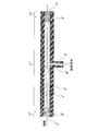
- the drawing chamber 1 has a portion that extends horizontally from the fiber inlet 2 to the roll 20 and a portion that extends vertically upward from the roll 20 to the fiber outlet 3.
- a liquid surface 21 of the drawing medium is formed at a position lower than the fiber outlet 3 in a portion extending vertically upward.
- the roll 20 changes the traveling direction of the fiber, particularly from horizontal to vertically upward.
- the stretching medium discharged from the stretching chamber 1 can be appropriately collected.
- the recovered stretching medium may be circulated in the stretching chamber 1 for reuse.
- the pressure loss (difference between the drawing medium and the drawing medium flowing in the drawing chamber 1 (including a diaphragm 8 portion described later) is greater than that in the case of a liquid. Pressure) becomes significantly large.
- the confirmation that boiling occurs before discharging from the fiber inlet 2 can be visually confirmed depending on the configuration of the apparatus.
- the case A when introducing the liquid from the drawing medium inlet 4, when the case A and the case B having the same flow rate but different temperatures are carried out (the temperature of the case A>the temperature of the case B), the case A is the case. If the pressure loss (differential pressure) is high, it is recognized that Case A has boiled. This is because the viscosity of the liquid is lower in the case A where the temperature is higher, so that the pressure loss (differential pressure) is lower unless boiling occurs.
- the pressure loss (differential pressure) when the drawing medium flows through the drawing chamber 1 becomes significantly large due to boiling, it is possible to increase the opening size of the fiber inlet 2 and the running fiber contacts the drawing device. And, as a result, it is easy to prevent yarn breakage or fluff from occurring in the fiber. There is no need for precise processing of the fiber inlet 2. It is also possible to increase the pressure of the drawing medium supplied to the drawing chamber 1, and thus to increase the pressure in the high-pressure in-liquid drawing step. This means that it is possible to draw the fibers in the drawing medium in the higher temperature liquid state.
- the pressure loss can be further increased by providing the throttle 8 at the fiber inlet 2.
- a labyrinth seal can be used as the diaphragm. However, it is not necessary to use a diaphragm, and the cross-sectional area of the drawing chamber (the area of the cross section orthogonal to the fiber running direction) may be constant.
- the throttle is a member that causes a pressure loss in the fluid by providing a narrowing structure in the fluid passage.
- the labyrinth seal is a member provided with throttles in multiple stages, and causes pressure loss in the fluid by repeatedly providing a narrowing structure and a widening structure in the flow path of the fluid.
- the drawing medium discharged from the fiber inlet 2 is typically a gas-liquid two-phase composed of vapor and liquid (particularly droplets) at ambient pressure.
- Method 1 A drawing medium in a liquid state having a temperature higher than the boiling point at the environmental pressure and higher than the environmental pressure is supplied from the drawing medium inlet 4 to the drawing chamber 1. At the stage of being discharged from the fiber inlet 2, the drawing medium is released to the ambient pressure, so that the drawing medium boils before being discharged from the fiber inlet.
- the stretching device having the configuration shown in FIG. 1 can be used.
- the drawing medium is supplied to the drawing chamber 1 from the drawing medium supply pipe 6 through the drawing medium inlet 4.
- the drawing medium at this stage is in a liquid state having a temperature higher than the boiling point at the ambient pressure and higher than the ambient pressure. Therefore, the drawing medium supply pipe 6 can be provided with a heater (not shown) for heating the drawing medium and a pump (not shown) for pressurizing the drawing medium, if necessary.
- regions 11 and 12 exist in this order between the drawing medium inlet 4 and the fiber inlet 2.
- the fiber inlet 2 refers to the most advanced position where fibers are introduced into the device, as shown in detail in FIG.
- the region 11 is a region in the stretching chamber 1 in which the stretching medium is a liquid having a temperature higher than the boiling point at the ambient pressure and higher than the ambient pressure.
- the region 11 can be present not only between the drawing medium inlet 4 and the fiber inlet 2 but also between the drawing medium inlet 4 and the fiber outlet.
- the fibers are drawn in the drawing medium in a liquid state having a higher pressure than the external environment.
- the pressure of the drawing medium is slightly or substantially not decreased as it flows in the drawing chamber 1, but is drastically decreased particularly when it flows in the throttle 8, and the saturated vapor of the drawing medium at that temperature is reached. Reach pressure. At that point, the drawing medium begins to boil, and in region 12 the drawing medium boils. That is, the drawing medium boils before being discharged from the fiber inlet 2.
- ambient pressure vapor and liquid (droplets) are discharged from the fiber inlet 2.
- the area 12 may not reach the fiber inlet 2. That is, there may be a region (not shown) on the fiber inlet 2 side of the region 12 from the region 12 toward the fiber inlet 2 in which the vapor and the liquid at the environmental pressure flow while maintaining the mass ratio of the vapor and the liquid.
- ⁇ Method 2 The temperature of the drawing medium (liquid having a pressure higher than the environmental pressure) supplied to the drawing chamber 1 is set to be equal to or lower than the boiling point at the environmental pressure. Then, in the drawing chamber, the drawing medium is heated to a temperature exceeding the boiling point at the environmental pressure. When the temperature of the heated drawing medium reaches the boiling point at the pressure at this stage, it is possible to adjust the heating position and the heating temperature by keeping in mind that the drawing medium boils.
- the stretching device having the configuration shown in FIG. 2 can be used.
- the drawing medium supplied to the drawing chamber 1 is heated to a temperature exceeding the boiling point at the environmental pressure by the heater 7 arranged outside or inside (not shown) of the container 5.
- the heater 7 is provided so that the drawing medium flowing from the drawing medium inlet 4 toward the fiber inlet 2 can be heated in this way.
- regions 13, 11 and 12 exist in this order from the drawing medium inlet 4 to the fiber inlet 2.
- the region 13 is a region in the stretching chamber in which the stretching medium is a liquid having a temperature equal to or lower than the boiling point at the ambient pressure and higher than the ambient pressure.
- the region 13 can be present not only between the drawing medium inlet 4 and the fiber inlet 2 but also between the drawing medium inlet 4 and the fiber outlet.
- the drawing medium flowing from the drawing medium inlet 4 toward the fiber inlet 2 is heated by the heater 7 and becomes a liquid having a temperature equal to or higher than the boiling point at the environmental pressure (region 11).
- region 12 the drawing medium boils.
- region 11, or in regions 11 and 13 the fibers are drawn in a drawing medium that is in a liquid state at a pressure higher than the external environment. Typically, ambient pressure vapor and liquid (droplets) are discharged from the fiber inlet 2.
- the temperature, pressure and flow rate of the drawing medium supplied to the drawing medium inlet 4 and the amount of heat when heating in the drawing chamber 1 can be adjusted. ..
- the drawing medium can be heated by a heater provided outside or inside the container 5 in order to reach a temperature at which the fiber can be drawn and deformed.
- a heater provided outside or inside the container 5 for example, in the method 2, the heater 7 provided on the fiber inlet 2 side with respect to the drawing medium inlet 4 can be used, and/or the heater (non-heater provided on the fiber outlet side with respect to the drawing medium inlet 4 can be used). Shown) can be used.
- a heater provided on the fiber inlet 2 side of the drawing medium inlet 4 can be used for this heating, and/or on the fiber outlet side of the drawing medium inlet.
- the heater provided in can be used.
- the drawing medium does not have to be boiled before being discharged from the fiber outlet.
- the drawing medium can be discharged from the fiber outlet in the state of a liquid having a pressure higher than the environmental pressure.
- the drawing medium may be cooled to the boiling point of the environmental pressure or lower between the drawing medium inlet 4 and the fiber outlet and discharged from the fiber outlet.
- the drawing medium may not be discharged from the fiber outlet, as described above with reference to FIG.
- the drawing medium can be boiled before being discharged from the fiber outlet.
- a method of boiling the drawing medium the same method as the above-mentioned method 1 or 2 can be adopted.
- a restriction, especially a labyrinth seal, may or may not be provided at the fiber outlet.
- the portion from the drawing medium inlet 4 to the fiber inlet 2 has the configuration shown in FIG. 1, and the temperature of the drawing medium (liquid having a pressure higher than the environmental pressure) supplied to the drawing chamber 1 exceeds the boiling point at the environmental pressure.
- the portion from the drawing medium inlet 4 to the fiber outlet can have the same configuration as the portion from the drawing medium inlet 4 to the fiber inlet 2 shown in FIG. In this case, regions 11 and 12 are present in this order between the drawing medium inlet 4 and the fiber outlet.
- a typical example in this case is shown in FIG.
- the fiber inlet 2 side and the fiber outlet 3 side are symmetrical with respect to the position of the drawing medium inlet 4.
- the portion from the drawing medium inlet 4 to the fiber inlet 2 has the configuration shown in FIG. 2, and the temperature of the drawing medium (liquid having a pressure higher than the environmental pressure) supplied to the drawing chamber 1 is set to be equal to or lower than the boiling point at the environmental pressure.
- the portion from the drawing medium inlet 4 to the fiber outlet can have the same configuration (configuration shown in FIG. 3) as described above. However, in this case, the region 13 exists between the drawing medium inlet 4 and the fiber outlet 3, the regions 11 and 12 do not exist, and the drawing medium is discharged from the fiber outlet 3 in a liquid state.
- the pressure of the drawing medium at the drawing medium inlet 4 is preferably 50 to 900 kPaG.
- G means a gauge pressure (atmospheric pressure is a reference of zero pressure, and a pressure higher than atmospheric pressure is a positive value).
- this pressure is more preferably 100 kPaG or more, further preferably 170 kPaG or more, and most preferably 270 kPaG or more.
- the load on the device can be reduced by setting it to 900 kPaG or less.
- this pressure is more preferably 700 kPaG or less, further preferably 500 kPaG or less, and most preferably 450 kPaG or less.
- the pressure of the stretching medium in the liquid state exceeds the saturated vapor pressure at the stretching temperature of the stretching medium.
- the pressure described here is particularly preferable when the environmental pressure is atmospheric pressure. If the environmental pressure is different from the atmospheric pressure, the gauge pressure should be read as a relative value to the environmental pressure (the environmental pressure is a reference of pressure 0, and the pressure higher than the environmental pressure is a positive value). Is preferred.
- the optimum temperature of the drawing medium in the region 11 varies depending on the material forming the fiber.
- the temperature is preferably 100 to 170°C.
- the temperature is 100° C. or higher, the mobility of molecules constituting the fiber is increased and the drawability can be enhanced, and when the temperature is 170° C. or lower, it is easy to draw while maintaining the fiber form without melting. Become.
- it is more preferably 120° C. or higher and 165° C. or lower, and further preferably 130° C. or higher and 160° C. or lower.
- the temperature is preferably 100 to 220°C.
- the temperature is 100° C. or higher, the mobility of the molecules constituting the fiber is enhanced and the stretchability can be enhanced, and when the temperature is 220° C. or lower, the stretching is performed while maintaining the quality without causing decomposition or flame resistance reaction. It will be easy.
- the temperature is more preferably 120° C. or higher and 200° C. or lower, and further preferably 130° C. or higher and 160° C. or lower.
- the temperature is preferably 150 to 340°C.
- the temperature is 150° C. or higher, the mobility of molecules constituting the fiber is enhanced and the stretchability can be enhanced, and when the temperature is 340° C. or lower, it is easy to stretch while maintaining the fiber form without melting. Become.
- the temperature is more preferably 200° C. or higher and 320° C. or lower, and further preferably 250° C. or higher and 300° C. or lower.
- the material of the fiber to be drawn is not particularly limited, and examples thereof include polypropylene, polyacrylonitrile, cellulose acetate, polyurethane, polyvinyl chloride, viscose rayon, nylon, polyester, polyether ether ketone (PEEK) and the like. Fiber bundles can be used as the fibers.
- the stretch deformation of the fibers preferably occurs in the area 11 in the case of the method 1, in the area 11 in the case of the method 2, or in the areas 11 and 13.
- the fibers it is permissible for the fibers to be drawn not only in regions 11 and 13 but also in region 12 where the drawing medium is boiling.
- the fiber inlet 2 side of the region 12 from the region 12 toward the fiber inlet 2 where the vapor and the liquid at the environmental pressure flow while maintaining the mass ratio of the vapor and the liquid, the fiber is stretched in that region. It is also permissible for some of the deformation to occur. It is also allowed that a part of the stretching deformation of the fiber occurs between the drawing medium inlet 4 and the fiber outlet 3 and further after exiting the fiber outlet 3.
- the drawing medium inlet 4 can be provided at a position closer to the fiber outlet than the center of the drawing chamber (the center in the fiber running direction). This is preferable when the heater is installed on the fiber inlet 2 side of the drawing medium inlet 4 and the heater is not installed on the fiber outlet side of the drawing medium inlet 4.
- the drawing medium inlet 4 can also be provided in the center of the drawing chamber.
- the drawing medium inlet 4 may be provided at a position closer to the fiber inlet 2 than the center of the drawing chamber.
- the stretching device shown in FIGS. 1, 2, 3 and 6 is a horizontal type. Therefore, the fiber yarn path is substantially horizontal.
- the present invention is not limited to this, and the stretching device may be a vertical type. Alternatively, as shown in FIG. 4, the stretching device may include a horizontal portion and a vertical portion.
- the shape of the cross section (cross section orthogonal to the fiber running direction) of the drawing chamber is not particularly limited, and is, for example, a circular shape or a rectangular shape (slit shape).
- the length of the region 12 is 30 mm or more, it is easy to obtain the effect of pressure loss utilizing the gas phase formed by boiling, and when it is 300 mm or less, the length of the region 12 is less than that of fluff due to rubbing of fibers. It is preferable from the viewpoint of preventing troubles. From the above, the length of the region 12 is preferably 30 mm or more and 300 mm or less, and more preferably 50 mm or more and 200 mm or less.
- the time (hereinafter, sometimes referred to as “pre-staying time”) t from when the fiber passes through the fiber inlet 2 to the temperature at which the fiber can be stretched and deformed is preferably It is 0.2 seconds or more, more preferably 0.5 seconds or more.
- the dimensions of the stretching chamber (in particular, the region 11) and the temperature of the stretching medium can be adjusted so that such a pre-residence time t can be achieved and a desired stretching can be performed thereafter.
- the minimum dimension of the cross section of the drawing chamber where there is no restriction is from 10 mm to 30 mm.
- the minimum dimension of the cross section of the drawing chamber is the diameter when the cross section of the drawing chamber is circular, and the length of the short side when the cross section of the drawing chamber is rectangular.
- the minimum dimension of the cross section of the drawing chamber is 10 mm or more, it is easy to slow down the speed of the drawing medium flowing in the drawing chamber, and it is easy to pass the fiber through the device without receiving a large resistance from the drawing medium. ..
- the minimum dimension of the cross section of the drawing chamber is 30 mm or less, it is easy to fill the drawing medium in the apparatus without using a large amount of drawing medium, and it is easy to efficiently produce drawn fibers.
- the occupation ratio of the fiber (fiber bundle) cross section with respect to the cross sectional area of the restriction is 2% or more and 70% or less. If the occupancy rate is 2% or more, it is easy to increase the pressure loss. When the occupancy rate is 70% or less, it is easy to prevent the fiber from hitting the device due to some trouble and causing quality deterioration such as yarn breakage and fluff.
- the occupation ratio of the cross section of the fiber (fiber bundle) to the cross-sectional area of the drawing chamber is 2% or more and 70% or less, as in the case of the throttle. ..
- the length of the diaphragm 8 may be relatively short.
- the length of the diaphragm 8 can be shorter than the lengths of the regions 11 and 13.
- the temperature difference can be increased inside the diaphragm 8. The larger the temperature difference between the inner side end and the outer side end of the drawing device 8 is, the easier the uniform drawing. From this viewpoint, the temperature difference is preferably 10° C. or higher, and more preferably 50° C. or higher.
- the drawing medium pressure at the inner end of the drawing device of the drawing device 8 is preferably 50 kPa or more higher than the environmental pressure, and more preferably 400 kPa or more higher than the environmental pressure. ..
- the pressure described here is particularly preferable when the environmental pressure is atmospheric pressure.
- the drawing medium flowing from the drawing medium inlet 4 to the fiber inlet 2 has the function of raising the temperature of the fibers introduced from the fiber inlet 2 and the function of absorbing the heat generated when the fibers in the drawing device are drawn and deformed.
- the flow rate of the drawing medium flowing from the drawing medium inlet 4 to the fiber inlet 2 is 10 times or more the volume of the fibers introduced from the fiber inlet 2 per unit time. Is preferred.
- the flow rate of the stretching medium is preferably 1 L/min (1 liter per 60 seconds) or more. From the viewpoint of damage to the fibers, the flow rate of the drawing medium is preferably 20 L/min or less.
- the flow rate of the drawing medium flowing from the drawing medium inlet 4 to the fiber outlet is not particularly limited, but a low flow rate is preferable.
- the fiber introduction speed and the fiber extraction speed can be appropriately determined depending on the desired draw ratio and productivity, but the fiber introduction speed is preferably 1 m/min (1 meter per 60 seconds) or more from the viewpoint of productivity. Further, it is preferable that the fiber delivery speed is 4000 m/min or less from the viewpoint of safety during production.
- Fiber polypropylene fiber (manufactured by Nippon Polypro Co., trade name "SA01A", melt flow rate: 10 g/10 minutes (230°C, load 2.16 kg), fineness of fiber bundle before stretching: 9260 dtex, number of filaments of fiber bundle: 240),
- Drawing chamber cylindrical, diameter 26 mm, length 2.4 m (distance in fiber running direction from fiber inlet to fiber outlet),
- Labyrinth seal 8 steps, small diameter 4 mm, large diameter 22 mm, length about 175 mm.
- the tensile strength and tensile elongation of the obtained fiber were measured. In addition, the presence or absence of whitening of the fibers was visually confirmed. The results are shown in Table 1.
- the temperature of the drawing medium did not substantially change from the drawing medium inlet 4 to the region 11, dropped sharply in the region 12, and was 100° C. at the fiber inlet 2 and the fiber outlet 3. Boiling was confirmed at the fiber inlet 2 and the fiber outlet 3, and a gas-liquid two-phase flow (steam and droplets) was discharged from each.
- Example 1 although the fiber was drawn with a high productivity of 160 m/min, the fiber did not whiten.
- Example 1-2 The same experiment as in Example 1 was performed except that a sight glass was attached to the stretching chamber 1 of the stretching device used in Example 1 so that the inside of the stretching chamber could be observed. It was confirmed that water vapor and hot water were jetted from the fiber inlet 2 in a mixed state, and the fiber bundle was filled with the liquid without bringing air into the drawing chamber.
- Example 2 The same test as in Example 1 was performed except that the conditions were changed as described in Table 1. The evaluation results are shown in Table 1. The temperature of the drawing medium did not substantially change from the drawing medium inlet 4 to the region 11, dropped sharply in the region 12, and was 100° C. at the fiber inlet 2 and the fiber outlet 3. Boiling was confirmed at the fiber inlet 2 and the fiber outlet 3, and a gas-liquid two-phase flow (steam and droplets) was discharged from them. In Example 2, although the fiber was drawn with a high productivity of 160 m/min, the fiber did not whiten.
- Example 2-2 The same experiment as in Example 2 was carried out except that a sight glass was attached to the stretching chamber 1 of the stretching device used in Example 2 so that the state inside the stretching chamber could be observed. It was confirmed that water vapor and hot water were jetted from the fiber inlet 2 in a mixed state, and the fiber bundle was filled with the liquid without bringing air into the drawing chamber.
- Example 1 The same test as in Example 1 was performed except that the stretching medium was steam as described in Table 1 and the steam pressure was adjusted so that the stretching medium temperature at the inlet of the stretching medium was the same as in Example 1. As shown in the evaluation results in Table 1, the fibers were whitened.
- Example 3 A stretching device having the configuration shown in FIG. 6 was prepared.
- This drawing apparatus looks the same as the drawing apparatus used in Example 1 (see FIG. 3) in a schematic sectional view, but the drawing chamber of the drawing apparatus of Example 1 is cylindrical (perpendicular to the fiber running direction). While the cross section was circular), the drawing chamber of the drawing apparatus of Example 3 had a rectangular parallelepiped shape (the cross section orthogonal to the fiber running direction was rectangular).
- drawing chamber 1' Each component (drawing chamber 1', fiber inlet 2', fiber outlet 3', drawing medium inlet 4', container 5', drawing medium supply pipe 6', throttle 8', region 11' and region 12')
- the drawing chamber 1′ and the throttle (labyrinth seal) 8′ were configured so that their cross sections orthogonal to the fiber running direction were rectangular.
- the drawing medium inlet 4' was provided at the center of the drawing chamber in the fiber running direction.
- a labyrinth seal having the same structure was provided as a diaphragm 8'on each of the fiber inlet 2'and the fiber outlet 3'.
- the fiber drawing speed was gradually changed (increased) under the conditions shown in Table 2 and below, and the fibers were drawn until they were broken.
- Environmental pressure atmospheric pressure
- Fiber acrylic fiber (single yarn fineness 3dtex)
- Drawing chamber rectangular parallelepiped, the drawing chamber cross section (cross section orthogonal to the fiber running direction) is a rectangle of 30 mm in the vertical direction and 38 mm in the horizontal direction, and the length of the drawing chamber is 2.00 m (fiber running from the fiber inlet to the fiber outlet. Direction distance)
- Labyrinth seal 32 stages of narrowing, width of narrowing structure part 2.0 mm, width of widening structure part 12 mm, length about 460 mm.
- Table 2 shows the draw ratio at break of the obtained fiber and the evaluation result of the drawability.
- the temperature of the drawing medium did not substantially change from the drawing medium inlet 4 to the region 11, dropped sharply in the region 12, and was 100° C. at the fiber inlet 2 and the fiber outlet 3. Boiling was confirmed at the fiber inlet 2 and the fiber outlet 3, and a gas-liquid two-phase flow (steam and droplets) was discharged from each.
- Example 3-2 The same experiment as in Example 3 was carried out except that a sight glass was attached to the stretching chamber 1 of the stretching device used in Example 3 so that the state inside the stretching chamber could be observed. It was confirmed that water vapor and hot water were jetted from the fiber inlet 2 in a mixed state, and the fiber bundle was filled with the liquid without bringing air into the drawing chamber.
- Example 2 The same test as in Example 3 was carried out except that the drawing medium was steamed as described in Table 2 and the steam pressure was adjusted so that the drawing medium temperature and pressure at the drawing medium inlet were the same as in Example 3. It was The evaluation results are shown in Table 2. In Example 3, it broke when stretched to 5.6 times, but in Comparative Example 2, it broke when stretched 4.2 times.
- Example 4 The same test as in Example 3 was carried out except that the width of the narrowed structure portion of the labyrinth seal was set to 2.5 mm and the conditions were changed as shown in Table 2. The evaluation results are shown in Table 2. The temperature of the drawing medium did not substantially change from the drawing medium inlet 4 to the region 11, dropped sharply in the region 12, and was 100° C. at the fiber inlet 2 and the fiber outlet 3. Boiling was confirmed at the fiber inlet 2 and the fiber outlet 3, and a gas-liquid two-phase flow (steam and droplets) was discharged from each.
- Example 4-2 An experiment similar to that in Example 4 was performed, except that a sight glass was attached to the stretching chamber 1 of the stretching device used in Example 4 so that the inside of the stretching chamber could be observed. It was confirmed that water vapor and hot water were jetted from the fiber inlet 2 in a mixed state, and the fiber bundle was filled with the liquid without bringing air into the drawing chamber.
- Example 3 The same test as in Example 4 was carried out except that the drawing medium was steamed as shown in Table 2 and the steam pressure was adjusted so that the drawing medium temperature and pressure at the drawing medium inlet were the same as in Example 4. It was The evaluation results are shown in Table 2. In Example 4, it broke when stretched up to 5.2 times, but in Comparative Example 3, it broke at a stretch of 3.4 times.
- Example 4 and Comparative Example 3 the fineness of the fiber bundle before stretching is twice that of Example 3 and Comparative Example 2. At this time, it was confirmed that the stretchability of Example 4 was less likely to decrease than that of Comparative Example 3.
- Stretching Chamber 2 Fiber Inlet 3 Fiber Outlet 4 Stretching Medium Inlet 5 Container 6
- Stretching Medium Supply Pipe 7 Heater 8 Throttling 11 Region 12 where the stretching medium is a liquid having a temperature above the boiling point at ambient pressure and higher than ambient pressure 12 Stretching Region in which the medium boils 13 Region in which the stretching medium is a liquid having a temperature equal to or lower than the boiling point at the ambient pressure and having a pressure higher than the ambient pressure 20 Roll 21 Liquid level
Landscapes
- Engineering & Computer Science (AREA)
- Textile Engineering (AREA)
- Yarns And Mechanical Finishing Of Yarns Or Ropes (AREA)
Abstract
繊維の白化を防止することができ、延伸性が繊維束の繊度の影響を受けにくい、延伸繊維の製造方法を提供する。外部環境に開放された繊維入口を有し前記外部環境より高圧の延伸媒体を収容する延伸室中に繊維を通過させて繊維を延伸することにより延伸繊維を得る延伸繊維の製造方法であって、前記外部環境より高圧の液体の状態の前記延伸媒体を前記延伸室に供給する工程と、前記外部環境より高圧の液体の状態の前記延伸媒体中で繊維を延伸する工程と、前記繊維入口を通して前記延伸媒体を排出する工程を有し、前記延伸媒体を、前記繊維入口から排出する前に沸騰させる
Description
本発明は、延伸媒体中に連続的に繊維を通過させて繊維を延伸することにより延伸繊維を得る、延伸繊維の製造方法に関する。
特許文献1には、加圧流体を満たした耐圧容器内で高分子材料長尺体を延伸する装置が開示される。この装置では、耐圧容器の長尺体供給口側に加圧流体導入口を設け、耐圧容器の長尺体取出口側に加圧流体排出口を設ける。また、長尺体取出口を、長尺体との間に生じる間隙から小量の加圧流体は流出するが耐圧容器内の圧力の低下を実質的なもたらさない寸法とする。長尺体供給口は、同様の寸法とするか、あるいは、長尺体が円滑に通過するが長尺体との間に生じる間隙から加圧流体が実質的に漏出しない寸法とする。延伸媒体として用いられる加圧流体は液体、気体のいずれでもよい。
特許文献1によれば、長尺体を連続的に処理する大量生産的な操作においても、長尺体の供給、取出しのための開口を設け、しかも内部の圧力を保持することが可能になるとされている。しかし、スチームなどの気体中で繊維を延伸する場合、繊維に白化が生じることがある。また、液体中に繊維を通過させて延伸する場合でも、繊維が白化することがある。
繊維が白化するメカニズムは以下のように考えられる。気体中で延伸する場合に比べて、液体中で延伸する場合のほうが、繊維が延伸される際の発熱をより効率的に除熱することができる。したがって、液体中で延伸する場合のほうが、発熱に伴って局所的に繊維が大きく延伸されることを防止しやすく、ひずみ速度が遅い延伸(ゆるやかな延伸)を実現しやすい。ひずみ速度が遅ければ、繊維径の変化(縮小)に対して、ポリマー分子が十分に再配置されやすい。そのため、液体中で延伸する場合のほうが、ボイドの無い高品質な繊維を得やすく、ボイドに起因して繊維が白化することを防止しやすい。液体中で繊維を延伸する場合であっても、繊維が液体中に気体を持ち込むことがある。気体が液体中に持ち込まれると、繊維が部分的に気体雰囲気下で延伸され、その部分で白化が生じると考えられる。
また、スチーム中で繊維を延伸する際、繊維束の繊度が大きい場合では繊維束の繊度が小さい場合と比較して延伸性が著しく低下することがある。スチーム中で繊維を延伸する場合、繊維束の外周部の繊維でスチームが凝縮し、スチームが気体として繊維束の内部に入りにくいからであると考えられる。一方、液体中で延伸する場合は延伸媒体の相転移を伴わないため、繊維束の内部と外周部との間で延伸性に差が出にくく、繊維束の繊度が大きい場合でも延伸性が低下しにくいと考えられる。
本発明の目的は、繊維の白化を防止することができ、延伸性が繊維束の繊度の影響を受けにくい、延伸繊維の製造方法を提供することである。
本発明の要旨は、以下の(1)~(7)に存する。
(1)外部環境に開放された繊維入口を有し前記外部環境より高圧の延伸媒体を収容する延伸室中に繊維を通過させて繊維を延伸することにより延伸繊維を得る延伸繊維の製造方法であって、
前記外部環境より高圧の液体の状態の前記延伸媒体を前記延伸室に供給する工程と、
前記外部環境より高圧の液体の状態の前記延伸媒体中で繊維を延伸する工程と、
前記繊維入口を通して前記延伸媒体を排出する工程を有し、
前記延伸媒体を、前記繊維入口から排出する前に沸騰させることを特徴とする延伸繊維の製造方法。
(1)外部環境に開放された繊維入口を有し前記外部環境より高圧の延伸媒体を収容する延伸室中に繊維を通過させて繊維を延伸することにより延伸繊維を得る延伸繊維の製造方法であって、
前記外部環境より高圧の液体の状態の前記延伸媒体を前記延伸室に供給する工程と、
前記外部環境より高圧の液体の状態の前記延伸媒体中で繊維を延伸する工程と、
前記繊維入口を通して前記延伸媒体を排出する工程を有し、
前記延伸媒体を、前記繊維入口から排出する前に沸騰させることを特徴とする延伸繊維の製造方法。
(2)前記繊維入口が大気開放された上記(1)に記載の延伸繊維の製造方法。
(3)前期延伸室が前記外部環境に開放された繊維出口を有し、
前記繊維出口を通して前記延伸媒体を排出する工程を有する上記(1)または(2)に記載の延伸繊維の製造方法。
前記繊維出口を通して前記延伸媒体を排出する工程を有する上記(1)または(2)に記載の延伸繊維の製造方法。
(4)前記沸騰を行うために、前記延伸室に供給する前記延伸媒体の温度を、前記外部環境の圧力における沸点を超える温度とする上記(1)~(3)のいずれか一項に記載の延伸繊維の製造方法。
(5)前記沸騰を行うために、前記延伸室に供給する前記延伸媒体の温度を、前記外部環境の圧力における沸点以下の温度とし、かつ、前記延伸室内で、前記外部環境の圧力における沸点を超える温度に前記延伸媒体を加熱する上記(1)~(3)のいずれか一項に記載の延伸繊維の製造方法。
(6)前記繊維入口に絞りを設ける、
上記(1)~(5)のいずれか一項に記載の延伸繊維の製造方法。
上記(1)~(5)のいずれか一項に記載の延伸繊維の製造方法。
(7)前記絞りがラビリンスシールである上記(6)に記載の延伸繊維の製造方法。
本発明によれば、繊維の白化を防止することができ、延伸性が繊維束の繊度の影響を受けにくい、延伸繊維の製造方法が提供される。
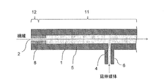
本発明は、延伸媒体を収容する延伸室中に繊維を通過させて繊維を延伸することにより延伸繊維を得る、延伸繊維の製造方法に関する。以下に本発明について、図面を参照して説明するが、本発明はこれによって限定されるものではない。図面において、同じ機能を有する部材には原則的に同一の符号を付し、また、紙面上方が鉛直上方と一致する。また、図1および図2は、延伸装置の、延伸媒体入口4付近から繊維入口2までの部分を示し、延伸装置全体を示すものではない。図1および図2では、延伸媒体入口4付近から繊維出口までの部分は図示を省略してある。図5は、延伸装置の繊維入口付近を部分的に示す。
図1~4、6に示すように、延伸装置は、延伸媒体を収容する延伸室1を含む。延伸室1は延伸媒体で満たされる。延伸室1は、繊維入口2と、繊維出口(図3、4、6では、繊維出口3)と、延伸媒体入口4とを備える。延伸室1は、容器5の内部の空間で形成される。繊維入口2は、延伸室1に繊維を導入する容器5の開口である。繊維入口2は外部環境、すなわち延伸装置(特には容器5)の外部の環境、に開放される。繊維出口は、延伸室1から繊維を排出するための、容器5の開口である。繊維出口も外部環境に開放される。延伸媒体入口4は、外部環境より高圧の延伸媒体を延伸室1に供給するための、容器5の開口である。外部から延伸装置に延伸媒体を供給するための延伸媒体供給管6が、延伸媒体入口4に接続される。なお、典型的には延伸室1の全体が延伸媒体で満たされるが(図1等)、後に図4を用いて説明するように、繊維出口3とその近傍に延伸媒体が存在しない部分があってもよい。
容器5の外部の環境の圧力(以下、「環境圧力」ということがある)は負圧でもよい。環境圧力を負圧とすることにより、後に詳述する沸騰のために、減圧沸騰を利用することが出来る。あるいは、容器5の外部の環境は大気であってもよく、環境圧力を大気圧とすることは、設備を簡素化できる面から好ましい。環境圧力が大気圧である場合は、延伸媒体は延伸媒体入口4から供給するために、大気圧を超える圧力に加圧することができる。あるいは、環境圧力が大気圧を超えていても構わない。
延伸媒体としては、例えば水や、エタノールなどのアルコールおよびエチレングリコールやグリセリン等の多価アルコールが利用でき、その中でも特に水がコストや環境面で好ましい。
〔延伸媒体供給工程〕
延伸媒体は、外部環境より高圧の液体の状態で、延伸媒体入口4から延伸室1に供給される。特に環境圧力が大気圧の場合は、前記の通り延伸媒体は大気圧超に加圧されて延伸媒体入口4から供給される。このとき、後述する絞り8や沸騰による圧力損失(差圧)が生じることにより、延伸室1は大きく加圧され得る。延伸媒体が液体であることは、次のことを意味する。すなわち、当該延伸媒体の温度および圧力をそれぞれTおよびPと表し、圧力Pにおける延伸媒体の沸点をTaと表すと、T<Taである。換言すれば、温度Tにおける延伸媒体の飽和蒸気圧をPaと表すと、P>Paである。延伸媒体を加圧するために、延伸媒体供給管6に、必要に応じてポンプ(不図示)を設けることができる。
延伸媒体は、外部環境より高圧の液体の状態で、延伸媒体入口4から延伸室1に供給される。特に環境圧力が大気圧の場合は、前記の通り延伸媒体は大気圧超に加圧されて延伸媒体入口4から供給される。このとき、後述する絞り8や沸騰による圧力損失(差圧)が生じることにより、延伸室1は大きく加圧され得る。延伸媒体が液体であることは、次のことを意味する。すなわち、当該延伸媒体の温度および圧力をそれぞれTおよびPと表し、圧力Pにおける延伸媒体の沸点をTaと表すと、T<Taである。換言すれば、温度Tにおける延伸媒体の飽和蒸気圧をPaと表すと、P>Paである。延伸媒体を加圧するために、延伸媒体供給管6に、必要に応じてポンプ(不図示)を設けることができる。
〔高圧液中延伸工程〕
延伸室1に供給された、外部環境より高圧の液体の状態の延伸媒体中で、繊維を延伸する(以下、この工程を「高圧液中延伸工程」と呼ぶことがある)。換言すれば、高圧液中延伸工程において、外部環境より高圧の液体中で繊維が延伸変形する。繊維を延伸する際の延伸媒体(液体)の温度は、繊維が延伸変形可能な温度となるように設定する。延伸室1中に繊維を連続的に通過させ、その際に、例えば延伸装置の外に設けた複数のロール(不図示)を用いて、延伸装置への繊維の導入速度よりも、延伸装置からの繊維の導出速度を速くすることによって、繊維を連続的に延伸することができる。
延伸室1に供給された、外部環境より高圧の液体の状態の延伸媒体中で、繊維を延伸する(以下、この工程を「高圧液中延伸工程」と呼ぶことがある)。換言すれば、高圧液中延伸工程において、外部環境より高圧の液体中で繊維が延伸変形する。繊維を延伸する際の延伸媒体(液体)の温度は、繊維が延伸変形可能な温度となるように設定する。延伸室1中に繊維を連続的に通過させ、その際に、例えば延伸装置の外に設けた複数のロール(不図示)を用いて、延伸装置への繊維の導入速度よりも、延伸装置からの繊維の導出速度を速くすることによって、繊維を連続的に延伸することができる。
〔延伸媒体排出工程〕
延伸媒体は、延伸室1から、繊維入口2を通して排出される。繊維出口からも、延伸媒体を繊維出口から排出することができる。例えば図3に示すように繊維出口3を設ければ、延伸媒体は繊維出口3からも排出される。あるいは、例えば図4のように繊維出口3近傍に液柱を設けて延伸室に圧力をかけることができ、この場合は繊維出口3から延伸媒体は排出されない。具体的には、繊維出口3を繊維入口2よりも高い位置に配置し、繊維出口3と繊維入口2との高さの差に起因する液圧によって、延伸媒体が繊維出口3から排出しないようにすることができる。なお、この場合でも、蒸発した延伸媒体が繊維出口3から外部環境に散逸することはあり得る。図4に示す装置では、延伸室1は、繊維入口2からロール20まで水平に延在する部分と、ロール20から繊維出口3まで鉛直上方に延在する部分とを有する。鉛直上方に延在する部分には、繊維出口3よりも低い位置に延伸媒体の液面21が形成される。また、ロール20によって繊維の走行方向が変更、特には水平から鉛直上方に変更される。延伸室1から排出された延伸媒体は、適宜回収することができる。回収した延伸媒体を延伸室1に循環させて再利用してもよい。
延伸媒体は、延伸室1から、繊維入口2を通して排出される。繊維出口からも、延伸媒体を繊維出口から排出することができる。例えば図3に示すように繊維出口3を設ければ、延伸媒体は繊維出口3からも排出される。あるいは、例えば図4のように繊維出口3近傍に液柱を設けて延伸室に圧力をかけることができ、この場合は繊維出口3から延伸媒体は排出されない。具体的には、繊維出口3を繊維入口2よりも高い位置に配置し、繊維出口3と繊維入口2との高さの差に起因する液圧によって、延伸媒体が繊維出口3から排出しないようにすることができる。なお、この場合でも、蒸発した延伸媒体が繊維出口3から外部環境に散逸することはあり得る。図4に示す装置では、延伸室1は、繊維入口2からロール20まで水平に延在する部分と、ロール20から繊維出口3まで鉛直上方に延在する部分とを有する。鉛直上方に延在する部分には、繊維出口3よりも低い位置に延伸媒体の液面21が形成される。また、ロール20によって繊維の走行方向が変更、特には水平から鉛直上方に変更される。延伸室1から排出された延伸媒体は、適宜回収することができる。回収した延伸媒体を延伸室1に循環させて再利用してもよい。
〔沸騰工程(繊維入口側)〕
延伸室1に供給された延伸媒体を、繊維入口2から排出する前に、沸騰させる。延伸媒体が沸騰する際には、その体積が著しく大きくなり、延伸媒体が激しく流動する。その流動の勢いによって、繊維入口2から延伸室1に入る繊維による空気の持ち込みが抑制される。その結果、ボイドの発生が抑制され、白化が抑制される。また、延伸媒体が激しく流動すると、繊維束の繊度が大きい場合であっても繊維束の内部まで延伸媒体を入れ込みやすく、これにより繊維束の繊度が大きい場合でも延伸性が向上しやすいという効果もある。
延伸室1に供給された延伸媒体を、繊維入口2から排出する前に、沸騰させる。延伸媒体が沸騰する際には、その体積が著しく大きくなり、延伸媒体が激しく流動する。その流動の勢いによって、繊維入口2から延伸室1に入る繊維による空気の持ち込みが抑制される。その結果、ボイドの発生が抑制され、白化が抑制される。また、延伸媒体が激しく流動すると、繊維束の繊度が大きい場合であっても繊維束の内部まで延伸媒体を入れ込みやすく、これにより繊維束の繊度が大きい場合でも延伸性が向上しやすいという効果もある。
また、沸騰が生じると、沸騰による著しい体積の増加に起因して、液体の場合と比べて、延伸媒体が延伸室1(後述する、絞り8部分を含む)を流通する際の圧力損失(差圧)が、著しく大きくなる。繊維入口2から排出する前に沸騰が生じることの確認は、装置の構成によっては目視で行うことができる。あるいは、例えば、延伸媒体入口4から液体を導入するにあたり、流量が同じで温度のみが異なるケースAとケースBを実施した場合(ケースAの温度>ケースBの温度とする)、ケースAの方が圧力損失(差圧)が高ければケースAでは沸騰したと認められる。温度が高いケースAの方が液体の粘度は低いので、沸騰が起きていないならば圧力損失(差圧)は低くなるためである。
延伸媒体が延伸室1を流通する際の圧力損失(差圧)が沸騰により著しく大きくなれば、繊維入口2の開口寸法を大きくすることが可能であり、走行する繊維が延伸装置に接触すること、および、その結果繊維に糸切れや毛羽が生じることを防止することが容易である。繊維入口2の精密な加工も不要となる。また、延伸室1に供給する延伸媒体の圧力を高くすること、したがって、高圧液中延伸工程における圧力を高くすることも可能である。これは、より高温の液体の状態の延伸媒体中で、繊維を延伸することが可能となることを意味する。
繊維入口2に、絞り8を設けることによって、圧力損失(差圧)をより大きくすることができる。絞りとしてラビリンスシールを用いることができる。ただし、絞りを用いる必要はなく、延伸室の断面積(繊維走行方向に直交する断面の面積)が一定であってもよい。絞りは、流体の流路に狭化構造を設けることにより、流体に圧力損失を生じさせる部材である。ラビリンスシールは、絞りを多段階に設けた部材であり、流体の流路に狭化構造と広化構造を繰り返し設けることにより流体に圧力損失を生じさせるものである。絞り8を設ける場合、絞りにおける圧力損失が大きいので、絞りの中で沸騰を開始させること(後に詳述する領域11と領域12との境を絞り8の中に位置させること)が容易である。すなわち、絞りを設けていない箇所において、沸騰が開始しないようにすることが容易である。
繊維入口2から排出される延伸媒体は、典型的には、環境圧力における蒸気と液体(特には液滴)からなる気液二相である。
上記沸騰を実現するために、例えば、以下の手法1または2を採用することができる。
・手法1:
環境圧力における沸点を超える温度を有する環境圧力より高圧の液体の状態の延伸媒体を、延伸媒体入口4から延伸室1に供給する。繊維入口2から排出される段階で、延伸媒体は環境圧力へ開放されるので、延伸媒体は、繊維入口から排出される前に、沸騰する。
・手法1:
環境圧力における沸点を超える温度を有する環境圧力より高圧の液体の状態の延伸媒体を、延伸媒体入口4から延伸室1に供給する。繊維入口2から排出される段階で、延伸媒体は環境圧力へ開放されるので、延伸媒体は、繊維入口から排出される前に、沸騰する。
手法1を採用する場合、図1に示す構成を有する延伸装置を用いることができる。延伸媒体供給管6から延伸媒体入口4を経て延伸媒体を延伸室1に供給する。この段階の延伸媒体を、環境圧力における沸点を超える温度を有する環境圧力より高圧の液体の状態とする。そのために、延伸媒体供給管6に、延伸媒体を加熱するためのヒーター(不図示)や、延伸媒体を加圧するためのポンプ(不図示)を必要に応じて設けることができる。
図1に示す例においては、延伸媒体入口4から繊維入口2までの間に、領域11および12がこの順に存在する。繊維入口2とは、図5に詳細を示すように、繊維が装置に導入される最先端の位置を言う。領域11は、延伸室1内の、延伸媒体が、環境圧力における沸点を超える温度を有する環境圧力より高圧の液体である領域である。領域11は、延伸媒体入口4から繊維入口2までの間だけでなく、延伸媒体入口4から繊維出口までの間にも存在することができる。領域11において、外部環境より高圧の液体の状態の延伸媒体中で、繊維が延伸される。延伸媒体の圧力は、延伸室1内を流れるにつれてわずかに低下するか実質的には低下しない程度であるが、特に絞り8内を流れる際に急激に低下し、その温度における延伸媒体の飽和蒸気圧に達する。その時点で延伸媒体が沸騰を開始し、領域12において延伸媒体が沸騰する。つまり、延伸媒体は、繊維入口2から排出される前に沸騰する。典型的には、繊維入口2から、環境圧力の蒸気および液体(液滴)が排出される。領域12が繊維入口2に達しなくてもよい。つまり、領域12より繊維入口2側に、領域12から繊維入口2に向かって環境圧力の蒸気および液体が蒸気と液体の質量比率を保ったまま流れる領域(不図示)が存在してもよい。
・手法2:
延伸室1に供給する延伸媒体(環境圧力より高圧の液体)の温度を、環境圧力における沸点以下とする。そして、延伸室内で、環境圧力における沸点を超える温度に、延伸媒体を加熱する。加熱された延伸媒体の温度がこの段階の圧力における沸点に達すると、延伸媒体が沸騰することに留意して、加熱の位置や加熱温度を調整することができる。
延伸室1に供給する延伸媒体(環境圧力より高圧の液体)の温度を、環境圧力における沸点以下とする。そして、延伸室内で、環境圧力における沸点を超える温度に、延伸媒体を加熱する。加熱された延伸媒体の温度がこの段階の圧力における沸点に達すると、延伸媒体が沸騰することに留意して、加熱の位置や加熱温度を調整することができる。
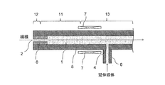
手法2を採用する場合、図2に示す構成を有する延伸装置を用いることができる。延伸室1に供給された延伸媒体は、容器5の外側または内側(図示しない)に配置されたヒーター7によって、環境圧力における沸点を超える温度に加熱される。ヒーター7は、延伸媒体入口4から繊維入口2に向かって流れる延伸媒体を、このように加熱できるように設ける。
図2に示す例においては、延伸媒体入口4から繊維入口2までに、領域13、11および12がこの順に存在する。領域13は、延伸室内の、延伸媒体が環境圧力における沸点以下の温度を有する環境圧力より高圧の液体である領域である。領域13は、延伸媒体入口4から繊維入口2までの間だけでなく、延伸媒体入口4から繊維出口までの間にも存在することができる。延伸媒体入口4から繊維入口2に向かって流れる延伸媒体は、ヒーター7によって加熱され、環境圧力における沸点以上の温度を有する液体となる(領域11)。領域12において、延伸媒体が沸騰する。領域11において、あるいは領域11および13において、外部環境より高圧の液体の状態の延伸媒体中で、繊維が延伸される。典型的には、繊維入口2から、環境圧力の蒸気および液体(液滴)が排出される。
いずれの場合も、沸騰が開始する位置を調節するために、延伸媒体入口4に供給する延伸媒体の温度、圧力および流量、ならびに延伸室1内で加熱する際の熱量などを調節することができる。
なお、必要に応じて、繊維を延伸変形可能な温度にするために、容器5の外側または内側に設けたヒーターで延伸媒体を加熱することができる。この加熱のために、例えば、手法2において、延伸媒体入口4より繊維入口2側に設けたヒーター7を用いることができ、かつ/または、延伸媒体入口4より繊維出口側に設けたヒーター(不図示)を用いることができる。また図1には示さないが、手法1においても、この加熱のために、延伸媒体入口4より繊維入口2側に設けたヒーターを用いることができ、かつ/または、延伸媒体入口より繊維出口側に設けたヒーターを用いることができる。
〔繊維出口側〕
繊維出口側では、繊維が空気を持ち込む現象は発生しない。したがって、延伸媒体を、繊維出口から排出する前に、沸騰させなくてよい。例えば、上記の手法2を採用して、環境圧力より高圧の液体の状態で、延伸媒体を繊維出口から排出することができる。また、手法1を採用して延伸媒体入口4から繊維出口までの間に延伸媒体を環境圧力の沸点以下に冷却して繊維出口から排出してもよい。あるいは、図4を用いて先に説明したように、延伸媒体を繊維出口から排出しなくてもよい。
繊維出口側では、繊維が空気を持ち込む現象は発生しない。したがって、延伸媒体を、繊維出口から排出する前に、沸騰させなくてよい。例えば、上記の手法2を採用して、環境圧力より高圧の液体の状態で、延伸媒体を繊維出口から排出することができる。また、手法1を採用して延伸媒体入口4から繊維出口までの間に延伸媒体を環境圧力の沸点以下に冷却して繊維出口から排出してもよい。あるいは、図4を用いて先に説明したように、延伸媒体を繊維出口から排出しなくてもよい。
ただし、繊維出口側でも圧力損失(差圧)を大きくするために、延伸媒体を、繊維出口から排出する前に、沸騰させることができる。延伸媒体を沸騰させる手法としては、前述の手法1もしくは2と同様の手法を採用することができる。繊維出口に絞り、特にはラビリンスシール、を設けても、設けなくてもよい。
例えば、延伸媒体入口4から繊維入口2までの部分が図1に示した構成を有し、延伸室1に供給する延伸媒体(環境圧力より高圧の液体)の温度を、環境圧力における沸点を超える温度にする(手法1)場合、延伸媒体入口4から繊維出口までの部分は、図1に示した延伸媒体入口4から繊維入口2までの部分の構成と同様の構成を有することができる。この場合、延伸媒体入口4から繊維出口までの間に、領域11および12がこの順に存在する。この場合の典型例を、図3に示す。延伸媒体入口4の位置を境に、繊維入口2側と繊維出口3側は対称な構成を有する。
また、延伸媒体入口4から繊維入口2までの部分が図2に示した構成を有し、延伸室1に供給する延伸媒体(環境圧力より高圧の液体)の温度を、環境圧力における沸点以下とする(手法2)場合も、延伸媒体入口4から繊維出口までの部分は、上記と同様の構成(図3に示した構成)を有することができる。ただし、この場合は、延伸媒体入口4から繊維出口3までの間に、領域13が存在し、領域11および12は存在せず、延伸媒体が液体の状態で繊維出口3から排出される。
〔延伸媒体の温度・圧力〕
延伸媒体入口4における延伸媒体の圧力は50~900kPaGであることが好ましい。圧力の単位において「G」はゲージ圧(大気圧を圧力0の基準とし、大気圧よりも高い圧力を正の値とした圧力)を意味する。50kPaG以上であることで、液体を安定的に加圧することが容易となる。前記理由より、この圧力は、より好ましくは100kPaG以上、さらに好ましくは170kPaG以上、最も好ましくは270kPaG以上である。また、900kPaG以下であることで、装置への負荷を軽減できる。前記理由より、この圧力は、より好ましくは700kPaG以下、さらに好ましくは500kPaG以下、最も好ましくは450kPaG以下である。なお、液体の状態の延伸媒体(延伸を行う部分)の圧力は、延伸媒体の延伸温度での飽和蒸気圧を超える。なお、ここに述べた圧力は、特には環境圧力が大気圧である場合に好ましい。環境圧力が大気圧と異なる場合には、ゲージ圧を環境圧力に対する相対値(環境圧力を圧力0の基準とし、環境圧力よりも高い圧力を正の値とした圧力)に読み替えた圧力とすることが好ましい。
延伸媒体入口4における延伸媒体の圧力は50~900kPaGであることが好ましい。圧力の単位において「G」はゲージ圧(大気圧を圧力0の基準とし、大気圧よりも高い圧力を正の値とした圧力)を意味する。50kPaG以上であることで、液体を安定的に加圧することが容易となる。前記理由より、この圧力は、より好ましくは100kPaG以上、さらに好ましくは170kPaG以上、最も好ましくは270kPaG以上である。また、900kPaG以下であることで、装置への負荷を軽減できる。前記理由より、この圧力は、より好ましくは700kPaG以下、さらに好ましくは500kPaG以下、最も好ましくは450kPaG以下である。なお、液体の状態の延伸媒体(延伸を行う部分)の圧力は、延伸媒体の延伸温度での飽和蒸気圧を超える。なお、ここに述べた圧力は、特には環境圧力が大気圧である場合に好ましい。環境圧力が大気圧と異なる場合には、ゲージ圧を環境圧力に対する相対値(環境圧力を圧力0の基準とし、環境圧力よりも高い圧力を正の値とした圧力)に読み替えた圧力とすることが好ましい。
領域11における延伸媒体の最適な温度は繊維を構成する素材によって異なる。
例えば繊維がポリプロピレンの場合、当該温度は100~170℃であることが好ましい。100℃以上であることで、繊維を構成する分子の運動性が高まり延伸性を高めることができ、170℃以下であることで、溶融することなく繊維形態を保ったまま延伸することが容易となる。前記理由より、120℃以上165℃以下であることがより好ましく、130℃以上160℃以下であることがさらに好ましい。
例えば繊維がポリプロピレンの場合、当該温度は100~170℃であることが好ましい。100℃以上であることで、繊維を構成する分子の運動性が高まり延伸性を高めることができ、170℃以下であることで、溶融することなく繊維形態を保ったまま延伸することが容易となる。前記理由より、120℃以上165℃以下であることがより好ましく、130℃以上160℃以下であることがさらに好ましい。
例えば繊維がポリアクリロニトリルの場合、当該温度は100~220℃であることが好ましい。100℃以上であることで、繊維を構成する分子の運動性が高まり延伸性を高めることができ、220℃以下であることで、分解や耐炎化反応を起こすことなく品質を保ったまま延伸することが容易となる。前記理由より、120℃以上200℃以下であることがより好ましく、130℃以上160℃以下であることがさらに好ましい。
また、例えば繊維が耐熱材料としても知られるPEEK(ポリエーテルエーテルケトン)の場合、当該温度は150~340℃であることが好ましい。150℃以上であることで、繊維を構成する分子の運動性が高まり延伸性を高めることができ、340℃以下であることで、溶融することなく繊維形態を保ったまま延伸することが容易となる。前記理由より、当該温度は200℃以上320℃以下であることがより好ましく、250℃以上300℃以下であることがさらに好ましい。
[繊維]
延伸する繊維の材料には特に制限はなく、例えばポリプロピレン、ポリアクリロニトリル、酢酸セルロース、ポリウレタン、ポリ塩化ビニル、ビスコースレーヨン、ナイロン、ポリエステル、ポリエーテルエーテルケトン(PEEK)等が例示できる。繊維として繊維束を使用することができる。
延伸する繊維の材料には特に制限はなく、例えばポリプロピレン、ポリアクリロニトリル、酢酸セルロース、ポリウレタン、ポリ塩化ビニル、ビスコースレーヨン、ナイロン、ポリエステル、ポリエーテルエーテルケトン(PEEK)等が例示できる。繊維として繊維束を使用することができる。
〔延伸変形が生じる領域〕
繊維の延伸変形は、手法1の場合は領域11において生じることが好ましく、手法2の場合は領域11において、あるいは領域11および13において生じることが好ましい。但し、領域11および13だけでなく、延伸媒体が沸騰している領域12で繊維が延伸されることが許容される。また、領域12より繊維入口2側に、環境圧力の蒸気および液体が領域12から繊維入口2に向かって蒸気と液体の質量比率を保ったまま流れる領域が存在する場合、その領域において繊維の延伸変形の一部が生じることも許容される。また延伸媒体入口4から繊維出口3の間において、さらには繊維出口3を出た後において繊維の延伸変形の一部が生じることも許容される。
繊維の延伸変形は、手法1の場合は領域11において生じることが好ましく、手法2の場合は領域11において、あるいは領域11および13において生じることが好ましい。但し、領域11および13だけでなく、延伸媒体が沸騰している領域12で繊維が延伸されることが許容される。また、領域12より繊維入口2側に、環境圧力の蒸気および液体が領域12から繊維入口2に向かって蒸気と液体の質量比率を保ったまま流れる領域が存在する場合、その領域において繊維の延伸変形の一部が生じることも許容される。また延伸媒体入口4から繊維出口3の間において、さらには繊維出口3を出た後において繊維の延伸変形の一部が生じることも許容される。
〔延伸媒体入口の位置など〕
延伸媒体入口4を、延伸室の中央(繊維走行方向における中央)よりも繊維出口に近い位置に設けることができる。これは、延伸媒体入口4よりも繊維入口2側にヒーターを設置し、延伸媒体入口4よりも繊維出口側にヒーターを設置しない場合に好ましい。ただし、伸媒体入口4を、延伸室の中央に設けることもできる。あるいは、延伸媒体入口4を、延伸室の中央よりも繊維入口2に近い位置に設けてもよい。また、図1、2、3、6に示す延伸装置は横型である。したがって、繊維の糸道は、略水平である。しかしその限りではなく、延伸装置が縦型であってもよい。あるいは、図4に示すように、延伸装置が横型の部分と縦型の部分を含むこともできる。
延伸媒体入口4を、延伸室の中央(繊維走行方向における中央)よりも繊維出口に近い位置に設けることができる。これは、延伸媒体入口4よりも繊維入口2側にヒーターを設置し、延伸媒体入口4よりも繊維出口側にヒーターを設置しない場合に好ましい。ただし、伸媒体入口4を、延伸室の中央に設けることもできる。あるいは、延伸媒体入口4を、延伸室の中央よりも繊維入口2に近い位置に設けてもよい。また、図1、2、3、6に示す延伸装置は横型である。したがって、繊維の糸道は、略水平である。しかしその限りではなく、延伸装置が縦型であってもよい。あるいは、図4に示すように、延伸装置が横型の部分と縦型の部分を含むこともできる。
延伸室の断面(繊維走行方向に直交する断面)の形状は、特に限定されず、例えば円形または矩形(スリット状)である。
〔領域12の長さ〕
領域12の長さは、30mm以上であることで、沸騰により形成される気相を利用した圧力損失の効果を得ることが容易であり、300mm以下であることが、繊維の擦過による毛羽等のトラブル発生を防ぐ観点から好ましい。以上より、領域12の長さは30mm以上300mm以下であることが好ましく、50mm以上200mm以下であることがより好ましい。
領域12の長さは、30mm以上であることで、沸騰により形成される気相を利用した圧力損失の効果を得ることが容易であり、300mm以下であることが、繊維の擦過による毛羽等のトラブル発生を防ぐ観点から好ましい。以上より、領域12の長さは30mm以上300mm以下であることが好ましく、50mm以上200mm以下であることがより好ましい。
〔前滞在時間t〕
また、繊維を安定的に延伸する観点から、繊維が繊維入口2を通過してから延伸変形可能な温度になるまでの時間(以下、「前滞在時間」ということがある)tは、好ましくは0.2秒以上、より好ましくは0.5秒以上である。このような前滞在時間tが達成できるように、また、その後に所望の延伸が行われるように、延伸室(特には、領域11)の寸法や延伸媒体の温度を調整することができる。
また、繊維を安定的に延伸する観点から、繊維が繊維入口2を通過してから延伸変形可能な温度になるまでの時間(以下、「前滞在時間」ということがある)tは、好ましくは0.2秒以上、より好ましくは0.5秒以上である。このような前滞在時間tが達成できるように、また、その後に所望の延伸が行われるように、延伸室(特には、領域11)の寸法や延伸媒体の温度を調整することができる。
〔延伸室断面の寸法など〕
以下に、繊維入口2に絞りを設ける場合(繊維出口には絞りが存在してもしなくてもよい)について、延伸室断面(繊維走行方向に直交する断面)に関して説明する。絞りが無い部分の延伸室断面の最小寸法は10mm以上30mm以下が好ましい。延伸室断面の最小寸法は、延伸室の断面が円形の場合は直径、延伸室断面が矩形の場合は短辺の長さである。延伸室断面の最小寸法が10mm以上であれば、延伸室を流れる延伸媒体の速度を遅くすることが容易であり、延伸媒体から大きな抵抗を受けることなく装置内に繊維を通過させること容易である。また、延伸室断面の最小寸法が30mm以下であれば、延伸媒体を大量に使用しなくとも装置内に延伸媒体を満たすことが容易であり、効率良く延伸繊維を製造することが容易である。
絞りがある部分については、絞りの断面積に対する繊維(繊維束)断面の占有率が2%以上70%以下であることが好ましい。占有率が2%以上であれば、圧力損失を大きくつけることが容易である。占有率が70%以下であれば、繊維が何らかのトラブルで装置に当たり糸切れや毛羽などの品質低下が発生することを防ぐことが容易である。
一方、繊維入口にも繊維出口にも絞りを設けない場合、前記絞りの場合と同様に、延伸室断面積に対する繊維(繊維束)断面の占有率が2%以上70%以下であることが好ましい。
〔絞りの内側端および外側端の温度差〕
絞り8を用いる場合、絞り8の長さは比較的短くてよい。例えば、絞り8の長さは、領域11や領域13の長さと比較して短くすることができる。一方、絞り8の内部において、温度差を大きくすることができる。絞り8の延伸装置内部側端と外部側端における温度差が大きいほうが均一に延伸しやすく、この観点から当該温度差は10℃以上であることが好ましく、50℃以上であることがより好ましい。
また、この温度差をつけるためには、絞り8の延伸装置内部側端における延伸媒体圧力は環境圧力よりも50kPa以上高圧であることが好ましく、環境圧力よりも400kPa以上高圧であることがより好ましい。なお、ここに述べた圧力は、特には環境圧力が大気圧である場合に好ましい。
〔延伸媒体流量〕
延伸媒体入口4から繊維入口2に流れる延伸媒体は、繊維入口2から導入する繊維を昇温する作用と、延伸装置内の繊維が延伸変形する際に発生する熱を吸収する作用とを有する。このような点を考慮して、延伸媒体入口4から繊維入口2に流れる延伸媒体の流量(沸騰前の液体ベース)は、単位時間あたりに繊維入口2から導入される繊維の体積の10倍以上であることが好ましい。一般には、延伸媒体の当該流量は1L/分(60秒当たり1リットル)以上であることが好ましい。また、繊維に与えるダメージの観点から、延伸媒体の当該流量は20L/分以下であることが好ましい。
延伸媒体入口4から繊維出口に流れる延伸媒体の流量には特に制限はないが、流量が少ないことが好ましい。
〔繊維導入および導出速度〕
繊維導入速度および繊維導出速度は所望とする延伸倍率や生産性によって適宜決めることができるが、繊維導入速度は1m/分(60秒当たり1メートル)以上であることが生産性の観点から好ましい。また繊維導出速度は4000m/分以下であることが、生産時の安全性の面から好ましい。
繊維導入速度および繊維導出速度は所望とする延伸倍率や生産性によって適宜決めることができるが、繊維導入速度は1m/分(60秒当たり1メートル)以上であることが生産性の観点から好ましい。また繊維導出速度は4000m/分以下であることが、生産時の安全性の面から好ましい。
<参考実験>
〔参考実験1〕
図3に示す装置(実施例1で用いた装置)の延伸室1にサイトグラスを取り付け延伸室内部の様子を観察できるようにした。延伸室1の圧力が0kPaGで、80℃の湯水を5.0kg/分で延伸媒体供給部4へ供給した状態で、実施例1で用いたのと同じポリプロピレン繊維を、繊維導入速度および繊維導出速度を16.0m/分として延伸室内を通過させた。このとき、繊維入口2から熱水が噴出していても、多くの気泡を繊維束が延伸室内部に持ち込む様子が確認された。
〔参考実験1〕
図3に示す装置(実施例1で用いた装置)の延伸室1にサイトグラスを取り付け延伸室内部の様子を観察できるようにした。延伸室1の圧力が0kPaGで、80℃の湯水を5.0kg/分で延伸媒体供給部4へ供給した状態で、実施例1で用いたのと同じポリプロピレン繊維を、繊維導入速度および繊維導出速度を16.0m/分として延伸室内を通過させた。このとき、繊維入口2から熱水が噴出していても、多くの気泡を繊維束が延伸室内部に持ち込む様子が確認された。
〔参考実験2〕
参考実験1と同様に、図3に示す装置(実施例1で用いた装置)の延伸室1にサイトグラスを取り付け延伸室内部の様子を観察できるようにした。110℃の加圧熱水を5.0kg/分で延伸媒体供給部4へ供給した状態で延伸室1の圧力を50kPaGとして、実施例1で用いたのと同じポリプロピレン繊維を、繊維導入速度および繊維導出速度を16.0m/分として延伸室内を通過させた。このとき、繊維入口2から水蒸気と熱水が混合状態で噴出して、繊維束が空気を延伸室内部に持ち込むことなく延伸室が液体で満たされている様子が確認された。
参考実験1と同様に、図3に示す装置(実施例1で用いた装置)の延伸室1にサイトグラスを取り付け延伸室内部の様子を観察できるようにした。110℃の加圧熱水を5.0kg/分で延伸媒体供給部4へ供給した状態で延伸室1の圧力を50kPaGとして、実施例1で用いたのと同じポリプロピレン繊維を、繊維導入速度および繊維導出速度を16.0m/分として延伸室内を通過させた。このとき、繊維入口2から水蒸気と熱水が混合状態で噴出して、繊維束が空気を延伸室内部に持ち込むことなく延伸室が液体で満たされている様子が確認された。
〔参考実験3〕
参考実験1と同様に、図3に示す装置(実施例1で用いた装置)の延伸室1にサイトグラスを取り付け延伸室内部の様子を観察できるようにした。ドレインを除去した直後の160℃の飽和蒸気を延伸媒体供給部4へ供給した状態で延伸室1の圧力を520kPaGとして、延伸室内を観察すると、延伸室内部に液体が溜まることなく繊維入口2および繊維出口3から蒸気が排出される様子が確認された。
参考実験1と同様に、図3に示す装置(実施例1で用いた装置)の延伸室1にサイトグラスを取り付け延伸室内部の様子を観察できるようにした。ドレインを除去した直後の160℃の飽和蒸気を延伸媒体供給部4へ供給した状態で延伸室1の圧力を520kPaGとして、延伸室内を観察すると、延伸室内部に液体が溜まることなく繊維入口2および繊維出口3から蒸気が排出される様子が確認された。
〔参考実験4〕
図6に示す装置(実施例4で用いた装置)の延伸室1にサイトグラスを取り付け延伸室内部の様子を観察できるようにした。延伸室1の圧力が0kPaGで、80℃の湯水を9.8kg/分で延伸媒体供給部4へ供給した状態で、実施例4で用いたのと同じアクリル繊維を、繊維導入速度および繊維導出速度を15.0m/分として延伸室1内を通過させた。このとき、繊維入口2から熱水が噴出していても、繊維束が多くの気泡を延伸室内部に持ち込む様子が確認された。
図6に示す装置(実施例4で用いた装置)の延伸室1にサイトグラスを取り付け延伸室内部の様子を観察できるようにした。延伸室1の圧力が0kPaGで、80℃の湯水を9.8kg/分で延伸媒体供給部4へ供給した状態で、実施例4で用いたのと同じアクリル繊維を、繊維導入速度および繊維導出速度を15.0m/分として延伸室1内を通過させた。このとき、繊維入口2から熱水が噴出していても、繊維束が多くの気泡を延伸室内部に持ち込む様子が確認された。
〔参考実験5〕
図6に示す装置(実施例4で用いた装置)の延伸室1にサイトグラスを取り付け延伸室内部の様子を観察できるようにした。延伸室1の圧力が50kPaGで、110℃の加圧熱水を9.3kg/分で延伸媒体供給部4へ供給した状態で、実施例4で用いたのと同じアクリル繊維を、繊維導入速度および繊維導出速度を15.0m/分として延伸室内を通過させた。このとき、繊維入口2から水蒸気と熱水が混合状態で噴出して、繊維束が空気を延伸室内部に持ち込むことなく延伸室が液体で満たされている様子が確認された。
図6に示す装置(実施例4で用いた装置)の延伸室1にサイトグラスを取り付け延伸室内部の様子を観察できるようにした。延伸室1の圧力が50kPaGで、110℃の加圧熱水を9.3kg/分で延伸媒体供給部4へ供給した状態で、実施例4で用いたのと同じアクリル繊維を、繊維導入速度および繊維導出速度を15.0m/分として延伸室内を通過させた。このとき、繊維入口2から水蒸気と熱水が混合状態で噴出して、繊維束が空気を延伸室内部に持ち込むことなく延伸室が液体で満たされている様子が確認された。
〔参考実験6〕
図6に示す装置(実施例4で用いた装置)の延伸室1にサイトグラスを取り付け延伸室内部の様子を観察できるようにした。ドレインを除去した直後の141℃の飽和蒸気を延伸媒体供給部4へ供給した状態で延伸室1の圧力を270kPaGとして、延伸室内を観察すると、延伸室内部に液体が溜まることなく繊維入口2および繊維出口3から蒸気が排出される様子が確認された。
図6に示す装置(実施例4で用いた装置)の延伸室1にサイトグラスを取り付け延伸室内部の様子を観察できるようにした。ドレインを除去した直後の141℃の飽和蒸気を延伸媒体供給部4へ供給した状態で延伸室1の圧力を270kPaGとして、延伸室内を観察すると、延伸室内部に液体が溜まることなく繊維入口2および繊維出口3から蒸気が排出される様子が確認された。
[実施例1]
以下、実施例により本発明をより具体的にするが、本発明はこれらに限定されない。
図3に示す構成を有する延伸装置を用い、表1および以下に示す条件にて繊維を延伸した。なお、延伸媒体入口4は繊維走行方向において延伸室の中央に設けた。また、繊維入口2および繊維出口3のそれぞれに、同じ構造のラビリンスシールを絞り8として設けた。
環境圧力:大気圧、
繊維:ポリプロピレン繊維(日本ポリプロ社製、商品名「SA01A」、メルトフローレート:10g/10分(230℃、荷重2.16kg)、延伸前の繊維束の繊度:9260dtex、繊維束のフィラメント数:240)、
延伸室:円筒状、直径26mm、長さ2.4m(繊維入口から繊維出口までの繊維走行方向の距離)、
ラビリンスシール:8段の絞り、小径部直径4mm、大径部直径22mm、長さ約175mm。
得られた繊維の引張強度および引張伸度を測定した。また、目視により繊維の白化の有無を確認した。これらの結果を表1に示す。延伸媒体の温度は、延伸媒体入口4から領域11にかけては実質的に変化せず、領域12において急激に低下し、繊維入口2および繊維出口3においては100℃であった。繊維入口2および繊維出口3で沸騰が確認され、それぞれから気液二相流(水蒸気および液滴)が排出された。実施例1では、160m/minという高い生産性で延伸を行ったにもかかわらず、繊維が白化しなかった。
[実施例1-2]
実施例1に用いた延伸装置の延伸室1にサイトグラスを取り付け延伸室内部の様子を観察できるようにした以外は、実施例1と同様の実験を行った。繊維入口2から水蒸気と熱水が混合状態で噴出して、繊維束が空気を延伸室内部に持ち込むことなく延伸室が液体で満たされている様子が確認された。
実施例1に用いた延伸装置の延伸室1にサイトグラスを取り付け延伸室内部の様子を観察できるようにした以外は、実施例1と同様の実験を行った。繊維入口2から水蒸気と熱水が混合状態で噴出して、繊維束が空気を延伸室内部に持ち込むことなく延伸室が液体で満たされている様子が確認された。
[実施例2]
表1に記載のように条件を変更したこと以外は実施例1と同様の試験を行った。評価結果を表1に示す。延伸媒体の温度は、延伸媒体入口4から領域11にかけては実質的に変化せず、領域12において急激に低下し、繊維入口2および繊維出口3においては100℃であった。繊維入口2および繊維出口3で沸騰が確認され、それらから気液二相流(水蒸気および液滴)が排出された。実施例2では、160m/minという高い生産性で延伸を行ったにもかかわらず、繊維が白化しなかった。
表1に記載のように条件を変更したこと以外は実施例1と同様の試験を行った。評価結果を表1に示す。延伸媒体の温度は、延伸媒体入口4から領域11にかけては実質的に変化せず、領域12において急激に低下し、繊維入口2および繊維出口3においては100℃であった。繊維入口2および繊維出口3で沸騰が確認され、それらから気液二相流(水蒸気および液滴)が排出された。実施例2では、160m/minという高い生産性で延伸を行ったにもかかわらず、繊維が白化しなかった。
[実施例2-2]
実施例2に用いた延伸装置の延伸室1にサイトグラスを取り付け延伸室内部の様子を観察できるようにした以外は、実施例2と同様の実験を行った。繊維入口2から水蒸気と熱水が混合状態で噴出して、繊維束が空気を延伸室内部に持ち込むことなく延伸室が液体で満たされている様子が確認された。
実施例2に用いた延伸装置の延伸室1にサイトグラスを取り付け延伸室内部の様子を観察できるようにした以外は、実施例2と同様の実験を行った。繊維入口2から水蒸気と熱水が混合状態で噴出して、繊維束が空気を延伸室内部に持ち込むことなく延伸室が液体で満たされている様子が確認された。
[比較例1]
表1に記載のように延伸媒体をスチームとし、延伸媒体入口における延伸媒体温度が実施例1と同じになるようにスチームの圧力を調整したこと以外は実施例1と同様の試験を行った。評価結果を表1に示すように、繊維は白化した。
表1に記載のように延伸媒体をスチームとし、延伸媒体入口における延伸媒体温度が実施例1と同じになるようにスチームの圧力を調整したこと以外は実施例1と同様の試験を行った。評価結果を表1に示すように、繊維は白化した。
[実施例3]
図6に示す構成を有する延伸装置を用意した。この延伸装置は、実施例1(図3参照)で用いた延伸装置と、模式的断面図では同じように見えるが、実施例1の延伸装置の延伸室は円筒状(繊維走行方向に直交する断面が円形)であったのに対し、実施例3の延伸装置の延伸室は直方体状(繊維走行方向と直行する断面が矩形)であった。各構成要素(延伸室1’、繊維入口2’、繊維出口3’、延伸媒体入口4’、容器5’、延伸媒体供給管6’、絞り8’、領域11’および領域12’)は、延伸室1’および絞り(ラビリンスシール)8’の繊維走行方向に直交する断面が矩形となるように構成した。なお、延伸媒体入口4’は繊維走行方向において延伸室の中央に設けた。また、繊維入口2’および繊維出口3’のそれぞれに、同じ構造のラビリンスシールを絞り8’として設けた。
図6に示す構成を有する延伸装置を用意した。この延伸装置は、実施例1(図3参照)で用いた延伸装置と、模式的断面図では同じように見えるが、実施例1の延伸装置の延伸室は円筒状(繊維走行方向に直交する断面が円形)であったのに対し、実施例3の延伸装置の延伸室は直方体状(繊維走行方向と直行する断面が矩形)であった。各構成要素(延伸室1’、繊維入口2’、繊維出口3’、延伸媒体入口4’、容器5’、延伸媒体供給管6’、絞り8’、領域11’および領域12’)は、延伸室1’および絞り(ラビリンスシール)8’の繊維走行方向に直交する断面が矩形となるように構成した。なお、延伸媒体入口4’は繊維走行方向において延伸室の中央に設けた。また、繊維入口2’および繊維出口3’のそれぞれに、同じ構造のラビリンスシールを絞り8’として設けた。
この延伸装置を用い、表2および以下に示す条件にて、繊維導出速度を徐々に変化(増加)させて、破断するまで繊維を延伸した。
環境圧力:大気圧、
繊維:アクリル繊維(単糸繊度3dtex)
延伸室:直方体状、延伸室断面(繊維走行方向に直交する断面)は鉛直方向30mm、水平方向38mmの矩形であり、延伸室の長さは2.00m(繊維入口から繊維出口までの繊維走行方向の距離)、
ラビリンスシール:32段の絞り、狭化構造部幅2.0mm、広化構造部幅12mm、長さ約460mm。
環境圧力:大気圧、
繊維:アクリル繊維(単糸繊度3dtex)
延伸室:直方体状、延伸室断面(繊維走行方向に直交する断面)は鉛直方向30mm、水平方向38mmの矩形であり、延伸室の長さは2.00m(繊維入口から繊維出口までの繊維走行方向の距離)、
ラビリンスシール:32段の絞り、狭化構造部幅2.0mm、広化構造部幅12mm、長さ約460mm。
得られた繊維の破断時の延伸倍率、およびこれによる延伸性の評価結果を表2に示す。延伸媒体の温度は、延伸媒体入口4から領域11にかけては実質的に変化せず、領域12において急激に低下し、繊維入口2および繊維出口3においては100℃であった。繊維入口2および繊維出口3で沸騰が確認され、それぞれから気液二相流(水蒸気および液滴)が排出された。
[実施例3-2]
実施例3に用いた延伸装置の延伸室1にサイトグラスを取り付け延伸室内部の様子を観察できるようにした以外は、実施例3と同様の実験を行った。繊維入口2から水蒸気と熱水が混合状態で噴出して、繊維束が空気を延伸室内部に持ち込むことなく延伸室が液体で満たされている様子が確認された。
実施例3に用いた延伸装置の延伸室1にサイトグラスを取り付け延伸室内部の様子を観察できるようにした以外は、実施例3と同様の実験を行った。繊維入口2から水蒸気と熱水が混合状態で噴出して、繊維束が空気を延伸室内部に持ち込むことなく延伸室が液体で満たされている様子が確認された。
[比較例2]
表2に記載のように延伸媒体をスチームにし、延伸媒体入口における延伸媒体温度と圧力が実施例3と同じになるようにスチームの圧力を調整したこと以外は実施例3と同様の試験を行った。評価結果を表2に示す。実施例3では5.6倍まで延伸した際に破断したが、比較例2では4.2倍の延伸で破断してしまった。
表2に記載のように延伸媒体をスチームにし、延伸媒体入口における延伸媒体温度と圧力が実施例3と同じになるようにスチームの圧力を調整したこと以外は実施例3と同様の試験を行った。評価結果を表2に示す。実施例3では5.6倍まで延伸した際に破断したが、比較例2では4.2倍の延伸で破断してしまった。
[実施例4]
ラビリンスシールの狭化構造部幅を2.5mmにし、表2に記載のように条件を変更したこと以外は実施例3と同様の試験を行った。評価結果を表2に示す。延伸媒体の温度は、延伸媒体入口4から領域11にかけては実質的に変化せず、領域12において急激に低下し、繊維入口2および繊維出口3においては100℃であった。繊維入口2および繊維出口3で沸騰が確認され、それぞれから気液二相流(水蒸気および液滴)が排出された。
ラビリンスシールの狭化構造部幅を2.5mmにし、表2に記載のように条件を変更したこと以外は実施例3と同様の試験を行った。評価結果を表2に示す。延伸媒体の温度は、延伸媒体入口4から領域11にかけては実質的に変化せず、領域12において急激に低下し、繊維入口2および繊維出口3においては100℃であった。繊維入口2および繊維出口3で沸騰が確認され、それぞれから気液二相流(水蒸気および液滴)が排出された。
[実施例4-2]
実施例4に用いた延伸装置の延伸室1にサイトグラスを取り付け延伸室内部の様子を観察できるようにした以外は、実施例4と同様の実験を行った。繊維入口2から水蒸気と熱水が混合状態で噴出して、繊維束が空気を延伸室内部に持ち込むことなく延伸室が液体で満たされている様子が確認された。
実施例4に用いた延伸装置の延伸室1にサイトグラスを取り付け延伸室内部の様子を観察できるようにした以外は、実施例4と同様の実験を行った。繊維入口2から水蒸気と熱水が混合状態で噴出して、繊維束が空気を延伸室内部に持ち込むことなく延伸室が液体で満たされている様子が確認された。
[比較例3]
表2に記載のように延伸媒体をスチームにし、延伸媒体入口における延伸媒体温度と圧力が実施例4と同じになるようにスチームの圧力を調整したこと以外は実施例4と同様の試験を行った。評価結果を表2に示す。実施例4では5.2倍まで延伸した際に破断したが、比較例3では3.4倍の延伸で破断してしまった。
表2に記載のように延伸媒体をスチームにし、延伸媒体入口における延伸媒体温度と圧力が実施例4と同じになるようにスチームの圧力を調整したこと以外は実施例4と同様の試験を行った。評価結果を表2に示す。実施例4では5.2倍まで延伸した際に破断したが、比較例3では3.4倍の延伸で破断してしまった。
実施例4及び比較例3では、実施例3及び比較例2に対して、延伸前の繊維束の繊度が2倍になっている。このとき、実施例4のほうが、比較例3と比べて、延伸性が低下しにくいことが確認された。
[引張強度・引張伸度]
引張強度・引張伸度の測定は、JIS L 1013:2010に準じて行った。引張試験機(島津社製AG-IS)を用い、試験長200mm、引張速度200mm/分の条件で歪-応力曲線を雰囲気温度20℃、相対湿度65%の条件下で測定し、破断点の値から伸度を、破断点での応力から強度を求めた。10回測定を行い、その平均値を使用した。
引張強度・引張伸度の測定は、JIS L 1013:2010に準じて行った。引張試験機(島津社製AG-IS)を用い、試験長200mm、引張速度200mm/分の条件で歪-応力曲線を雰囲気温度20℃、相対湿度65%の条件下で測定し、破断点の値から伸度を、破断点での応力から強度を求めた。10回測定を行い、その平均値を使用した。
[繊度の測定方法]
繊維束を1m切り出してその質量を測る操作を10回行い、その平均から繊度を算出した。
繊維束を1m切り出してその質量を測る操作を10回行い、その平均から繊度を算出した。
1 延伸室
2 繊維入口
3 繊維出口
4 延伸媒体入口
5 容器
6 延伸媒体供給管
7 ヒーター
8 絞り
11 延伸媒体が、環境圧力における沸点を超える温度を有する、環境圧力より高圧の液体である領域
12 延伸媒体が沸騰する領域
13 延伸媒体が、環境圧力における沸点以下の温度を有する、環境圧力より高圧の液体である領域
20 ロール
21 液面
2 繊維入口
3 繊維出口
4 延伸媒体入口
5 容器
6 延伸媒体供給管
7 ヒーター
8 絞り
11 延伸媒体が、環境圧力における沸点を超える温度を有する、環境圧力より高圧の液体である領域
12 延伸媒体が沸騰する領域
13 延伸媒体が、環境圧力における沸点以下の温度を有する、環境圧力より高圧の液体である領域
20 ロール
21 液面


Claims (7)
- 外部環境に開放された繊維入口を有し前記外部環境より高圧の延伸媒体を収容する延伸室中に繊維を通過させて繊維を延伸することにより延伸繊維を得る延伸繊維の製造方法であって、
前記外部環境より高圧の液体の状態の前記延伸媒体を前記延伸室に供給する工程と、
前記外部環境より高圧の液体の状態の前記延伸媒体中で繊維を延伸する工程と、
前記繊維入口を通して前記延伸媒体を排出する工程を有し、
前記延伸媒体を、前記繊維入口から排出する前に沸騰させることを特徴とする延伸繊維の製造方法。 - 前記繊維入口が大気開放された請求項1に記載の延伸繊維の製造方法。
- 前期延伸室が前記外部環境に開放された繊維出口を有し、
前記繊維出口を通して前記延伸媒体を排出する工程を有する請求項1または2に記載の延伸繊維の製造方法。 - 前記沸騰を行うために、前記延伸室に供給する前記延伸媒体の温度を、前記外部環境の圧力における沸点を超える温度とする請求項1~3のいずれか一項に記載の延伸繊維の製造方法。
- 前記沸騰を行うために、前記延伸室に供給する前記延伸媒体の温度を、前記外部環境の圧力における沸点以下の温度とし、かつ、前記延伸室内で、前記外部環境の圧力における沸点を超える温度に前記延伸媒体を加熱する請求項1~3のいずれか一項に記載の延伸繊維の製造方法。
- 前記繊維入口に絞りを設ける、
請求項1~5のいずれか一項に記載の延伸繊維の製造方法。 - 前記絞りがラビリンスシールである請求項6に記載の延伸繊維の製造方法。
Priority Applications (1)
| Application Number | Priority Date | Filing Date | Title |
|---|---|---|---|
| JP2020520168A JP7318642B2 (ja) | 2018-11-29 | 2019-11-26 | 延伸繊維の製造方法 |
Applications Claiming Priority (2)
| Application Number | Priority Date | Filing Date | Title |
|---|---|---|---|
| JP2018-223127 | 2018-11-29 | ||
| JP2018223127 | 2018-11-29 |
Publications (1)
| Publication Number | Publication Date |
|---|---|
| WO2020111026A1 true WO2020111026A1 (ja) | 2020-06-04 |
Family
ID=70853963
Family Applications (1)
| Application Number | Title | Priority Date | Filing Date |
|---|---|---|---|
| PCT/JP2019/046066 WO2020111026A1 (ja) | 2018-11-29 | 2019-11-26 | 延伸繊維の製造方法 |
Country Status (2)
| Country | Link |
|---|---|
| JP (1) | JP7318642B2 (ja) |
| WO (1) | WO2020111026A1 (ja) |
Citations (6)
| Publication number | Priority date | Publication date | Assignee | Title |
|---|---|---|---|---|
| JPS5094221A (ja) * | 1973-12-26 | 1975-07-26 | ||
| JPS60193632A (ja) * | 1984-03-16 | 1985-10-02 | Asahi Chem Ind Co Ltd | 高分子材料の連続加圧延伸装置 |
| JPH03833A (ja) * | 1989-02-24 | 1991-01-07 | Mas Fab Rieter Ag | 合成繊維の流体力学的延伸方法及び装置 |
| JPH0544132A (ja) * | 1991-08-01 | 1993-02-23 | Mitsubishi Rayon Co Ltd | アクリル系重合体糸条の加圧スチーム延伸装置 |
| JPH0657573A (ja) * | 1992-06-09 | 1994-03-01 | Mitsubishi Rayon Co Ltd | 糸条の加圧スチーム処理装置及びその方法 |
| JPH08246284A (ja) * | 1995-03-06 | 1996-09-24 | Toray Ind Inc | スチーム延伸装置およびスチーム延伸方法 |
Family Cites Families (1)
| Publication number | Priority date | Publication date | Assignee | Title |
|---|---|---|---|---|
| JP5094221B2 (ja) | 2007-06-12 | 2012-12-12 | キヤノン株式会社 | 光走査装置及びそれを用いた画像形成装置 |
-
2019
- 2019-11-26 JP JP2020520168A patent/JP7318642B2/ja active Active
- 2019-11-26 WO PCT/JP2019/046066 patent/WO2020111026A1/ja active Application Filing
Patent Citations (6)
| Publication number | Priority date | Publication date | Assignee | Title |
|---|---|---|---|---|
| JPS5094221A (ja) * | 1973-12-26 | 1975-07-26 | ||
| JPS60193632A (ja) * | 1984-03-16 | 1985-10-02 | Asahi Chem Ind Co Ltd | 高分子材料の連続加圧延伸装置 |
| JPH03833A (ja) * | 1989-02-24 | 1991-01-07 | Mas Fab Rieter Ag | 合成繊維の流体力学的延伸方法及び装置 |
| JPH0544132A (ja) * | 1991-08-01 | 1993-02-23 | Mitsubishi Rayon Co Ltd | アクリル系重合体糸条の加圧スチーム延伸装置 |
| JPH0657573A (ja) * | 1992-06-09 | 1994-03-01 | Mitsubishi Rayon Co Ltd | 糸条の加圧スチーム処理装置及びその方法 |
| JPH08246284A (ja) * | 1995-03-06 | 1996-09-24 | Toray Ind Inc | スチーム延伸装置およびスチーム延伸方法 |
Also Published As
| Publication number | Publication date |
|---|---|
| JPWO2020111026A1 (ja) | 2021-10-14 |
| JP7318642B2 (ja) | 2023-08-01 |
Similar Documents
| Publication | Publication Date | Title |
|---|---|---|
| US8858851B2 (en) | Method for producing lower size, high tenacity and high modulus polyethylene fiber | |
| CN101568672B (zh) | 用于制备UHMW复丝聚(α-烯烃)纱的方法 | |
| US2371579A (en) | Method and apparatus for treating filamentary material | |
| EP3778999A1 (en) | Method for manufacturing acrylonitrilic fiber bundle and method for manufacturing carbon fiber bundle | |
| JP2008540850A5 (ja) | ||
| JP6149583B2 (ja) | 炭素繊維前駆体アクリル繊維束の延伸方法 | |
| WO2020111026A1 (ja) | 延伸繊維の製造方法 | |
| TW393527B (en) | Process for the production of a polyester multifilament yarn | |
| JP2002542402A (ja) | ポリマーフィラメントを紡糸するための装置および方法 | |
| TW584680B (en) | Device for intermingling, relaxing, and/or thermosetting of filament yarn in a melt spinning process, as well as associated processes and the filament yarn manufactured therewith | |
| JP2013159874A (ja) | アクリル繊維束の製造方法と同繊維束のスチーム延伸装置 | |
| JP4962361B2 (ja) | ポリフェニレンサルファイド繊維の製造方法およびポリフェニレンサルファイド繊維 | |
| CN111148866A (zh) | 高强度聚对苯二甲酸乙二醇酯纱线及其制造方法 | |
| CN103562452B (zh) | 碳纤维前体丙烯腈纤维束的制造方法 | |
| JP7010214B2 (ja) | アクリロニトリル系繊維束の製造方法および炭素繊維束の製造方法 | |
| US3693222A (en) | Yarn texturing apparatus | |
| JP4673095B2 (ja) | 加圧スチーム延伸装置およびアクリル系繊維の製造方法 | |
| JP2008075205A (ja) | 加圧スチームによる繊維の延伸方法及び延伸装置、並びに炭素繊維用アクリル系前駆体繊維束の製造方法 | |
| US3994052A (en) | Method and apparatus for texturing yarn | |
| EP3455395B1 (en) | Apparatus and method for monofilament yarn production | |
| WO2019189627A1 (ja) | 繊維延伸装置 | |
| JP6562187B1 (ja) | アクリロニトリル系繊維束の製造方法および炭素繊維束の製造方法 | |
| JP6265068B2 (ja) | 炭素繊維前駆体アクリル繊維束の製造方法 | |
| JP4332401B2 (ja) | 加圧スチーム延伸装置およびアクリル系繊維の製造方法 | |
| US1950025A (en) | Manufacture of artificial filaments or threads |
Legal Events
| Date | Code | Title | Description |
|---|---|---|---|
| ENP | Entry into the national phase |
Ref document number: 2020520168 Country of ref document: JP Kind code of ref document: A |
|
| 121 | Ep: the epo has been informed by wipo that ep was designated in this application |
Ref document number: 19888812 Country of ref document: EP Kind code of ref document: A1 |
|
| NENP | Non-entry into the national phase |
Ref country code: DE |
|
| 122 | Ep: pct application non-entry in european phase |
Ref document number: 19888812 Country of ref document: EP Kind code of ref document: A1 |