WO2020110901A1 - アブソリュートエンコーダ - Google Patents
アブソリュートエンコーダ Download PDFInfo
- Publication number
- WO2020110901A1 WO2020110901A1 PCT/JP2019/045610 JP2019045610W WO2020110901A1 WO 2020110901 A1 WO2020110901 A1 WO 2020110901A1 JP 2019045610 W JP2019045610 W JP 2019045610W WO 2020110901 A1 WO2020110901 A1 WO 2020110901A1
- Authority
- WO
- WIPO (PCT)
- Prior art keywords
- gear
- driven gear
- absolute encoder
- shaft
- intermediate gear
- Prior art date
Links
Images


Classifications
-
- G—PHYSICS
- G01—MEASURING; TESTING
- G01D—MEASURING NOT SPECIALLY ADAPTED FOR A SPECIFIC VARIABLE; ARRANGEMENTS FOR MEASURING TWO OR MORE VARIABLES NOT COVERED IN A SINGLE OTHER SUBCLASS; TARIFF METERING APPARATUS; MEASURING OR TESTING NOT OTHERWISE PROVIDED FOR
- G01D5/00—Mechanical means for transferring the output of a sensing member; Means for converting the output of a sensing member to another variable where the form or nature of the sensing member does not constrain the means for converting; Transducers not specially adapted for a specific variable
- G01D5/12—Mechanical means for transferring the output of a sensing member; Means for converting the output of a sensing member to another variable where the form or nature of the sensing member does not constrain the means for converting; Transducers not specially adapted for a specific variable using electric or magnetic means
- G01D5/244—Mechanical means for transferring the output of a sensing member; Means for converting the output of a sensing member to another variable where the form or nature of the sensing member does not constrain the means for converting; Transducers not specially adapted for a specific variable using electric or magnetic means influencing characteristics of pulses or pulse trains; generating pulses or pulse trains
- G01D5/245—Mechanical means for transferring the output of a sensing member; Means for converting the output of a sensing member to another variable where the form or nature of the sensing member does not constrain the means for converting; Transducers not specially adapted for a specific variable using electric or magnetic means influencing characteristics of pulses or pulse trains; generating pulses or pulse trains using a variable number of pulses in a train
-
- G—PHYSICS
- G01—MEASURING; TESTING
- G01D—MEASURING NOT SPECIALLY ADAPTED FOR A SPECIFIC VARIABLE; ARRANGEMENTS FOR MEASURING TWO OR MORE VARIABLES NOT COVERED IN A SINGLE OTHER SUBCLASS; TARIFF METERING APPARATUS; MEASURING OR TESTING NOT OTHERWISE PROVIDED FOR
- G01D5/00—Mechanical means for transferring the output of a sensing member; Means for converting the output of a sensing member to another variable where the form or nature of the sensing member does not constrain the means for converting; Transducers not specially adapted for a specific variable
- G01D5/12—Mechanical means for transferring the output of a sensing member; Means for converting the output of a sensing member to another variable where the form or nature of the sensing member does not constrain the means for converting; Transducers not specially adapted for a specific variable using electric or magnetic means
- G01D5/14—Mechanical means for transferring the output of a sensing member; Means for converting the output of a sensing member to another variable where the form or nature of the sensing member does not constrain the means for converting; Transducers not specially adapted for a specific variable using electric or magnetic means influencing the magnitude of a current or voltage
- G01D5/142—Mechanical means for transferring the output of a sensing member; Means for converting the output of a sensing member to another variable where the form or nature of the sensing member does not constrain the means for converting; Transducers not specially adapted for a specific variable using electric or magnetic means influencing the magnitude of a current or voltage using Hall-effect devices
- G01D5/145—Mechanical means for transferring the output of a sensing member; Means for converting the output of a sensing member to another variable where the form or nature of the sensing member does not constrain the means for converting; Transducers not specially adapted for a specific variable using electric or magnetic means influencing the magnitude of a current or voltage using Hall-effect devices influenced by the relative movement between the Hall device and magnetic fields
-
- G—PHYSICS
- G01—MEASURING; TESTING
- G01D—MEASURING NOT SPECIALLY ADAPTED FOR A SPECIFIC VARIABLE; ARRANGEMENTS FOR MEASURING TWO OR MORE VARIABLES NOT COVERED IN A SINGLE OTHER SUBCLASS; TARIFF METERING APPARATUS; MEASURING OR TESTING NOT OTHERWISE PROVIDED FOR
- G01D2205/00—Indexing scheme relating to details of means for transferring or converting the output of a sensing member
- G01D2205/20—Detecting rotary movement
- G01D2205/28—The target being driven in rotation by additional gears
Definitions
- the present invention relates to an absolute encoder.
- rotary encoders that are used to detect the position and angle of a movable element in various control machinery are known.
- encoders there are an incremental encoder that detects a relative position or angle and an absolute encoder that detects an absolute position or angle.
- an absolute encoder that detects an absolute position or angle.
- Patent Document 1 the rotation amount of a rotation shaft for motion control provided in a device such as an automatic control device or a robot device, or the rotation amount of a rotation shaft for power transmission used for opening and closing a valve provided in the device is described.
- An absolute type rotary encoder for digitally measuring an absolute amount is described.
- the absolute encoder described in Patent Document 1 is configured by stacking components such as a rotating disk, a slit, a light emitting element, and a light receiving element in the axial direction (height direction) of the shaft.
- the axial dimension of each of the plurality of components is stacked in the axial direction, so the axial dimension of the absolute encoder becomes large, and the axial dimension is reduced.
- it is difficult to reduce the size that is, to make the absolute encoder thinner.
- it is conceivable to make each of the above multiple parts thin but when each of the multiple parts becomes thin, the strength of the part decreases, and the part was subject to vibration and shock. It may be easily damaged.
- the present invention has been made in view of the above, and an object thereof is to provide an absolute encoder suitable for miniaturization.
- An absolute encoder is provided with a first drive gear that rotates according to rotation of a main shaft, a first driven gear that meshes with the first drive gear, and a first driven gear that is coaxial with the first driven gear. And a second drive gear that rotates according to the rotation of the driven gear.
- the absolute encoder includes a second driven gear that is provided on the opposite side of the first driven gear and the second driving gear from the first driving gear in plan view and meshes with the second driving gear.
- the absolute encoder includes an angle sensor that detects a rotation angle of a rotating body that rotates according to the rotation of the second driven gear.
- the absolute encoder according to the present invention has the effect of being downsized.
- FIG. 2 is a perspective view showing a state in which the case 15 and the mounting screw 16 are removed from the absolute encoder 100 shown in FIG.
- FIG. 3 is a perspective view showing a state in which the absolute encoder 100 is attached to the motor 200 and the motor 200 and the screw 14 are removed in FIG.
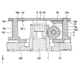
- FIG. 6 is a cross-sectional view of the absolute encoder 100 shown in FIG. 2 taken along a plane that passes through the center of the main shaft gear 1 shown in FIG. 5 and is perpendicular to the center line of the intermediate gear 2.
- the substrate 20 and the magnetic sensor 40 are not shown in cross section.
- FIG. 7 is a cross-sectional view of the absolute encoder 100 shown in FIG. 2 taken along a plane that passes through the center of the sub-shaft gear 5 shown in FIG. 6 and is perpendicular to the center line of the intermediate gear 2.
- FIG. 1 A perspective view showing a state in which the intermediate gear 2 is removed from the plurality of parts shown in FIG. A state in which the screw 12 is removed from the wall portion 70 shown in FIG. 10, a state of the leaf spring 11 after the screw 12 is removed, and a wall portion 70 provided with a leaf spring mounting surface 10e facing the leaf spring 11 are provided.
- FIG. 1 the motor 200 and the main shaft gear 1 are not shown. Sectional drawing which cut
- FIG. 1 is a perspective view of the case 15 shown in FIG. Sectional drawing which cut
- the motor 200 and the main shaft gear 1 are not shown in cross section.
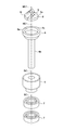
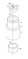
- FIG. 9 is an exploded perspective view of the permanent magnet 8, the magnet holder 6, the countershaft gear 5, and the bearing 7 shown in FIG.
- FIG. 8 is an exploded perspective view of the permanent magnet 9, the main shaft gear 1, and the motor shaft 201 shown in FIG.
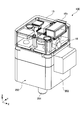
- FIG. 1 is a perspective view showing a state in which an absolute encoder 100 according to an embodiment of the present invention is attached to a motor 200.
- the components provided inside the case 15 of the absolute encoder 100 are transparently shown.
- the Z-axis positive direction is the upward direction and the Z-axis negative direction is the downward direction in the XYZ coordinate system.
- the Z-axis positive direction and the Z-axis negative direction mean universal vertical directions. Not something to do.
- the Z-axis direction is equal to the direction in which the main axis described below extends.
- the X-axis direction is equal to, for example, the arrangement direction of the substrate positioning pins 10j and the columns 10m described later, in the direction orthogonal to the Z-axis direction.
- the Y-axis direction is equal to the direction orthogonal to both the Z-axis direction and the X-axis direction.
- the notation and definition of the direction of each of these axes is the same in each drawing after FIG. In the present embodiment, looking at the absolute encoder 100 toward the Z axis is referred to as a plan view.
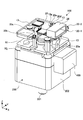
- FIG. 2 is a perspective view showing a state in which the case 15 and the mounting screw 16 are removed from the absolute encoder 100 shown in FIG.
- a plurality of components provided on the lower surface 20-1 of the substrate 20 are transparently shown.
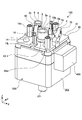
- FIG. 3 is a perspective view showing a state where the board 20 and the board mounting screw 13 are removed from the absolute encoder 100 shown in FIG.
- FIG. 4 is a perspective view showing a state in which the motor 200 and the screw 14 are removed from the perspective view in which the absolute encoder 100 shown in FIG. 3 is attached to the motor 200.
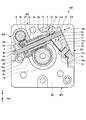
- FIG. 5 is a diagram showing a state in which the main base 10, the intermediate gear 2 and the like shown in FIG. 4 are viewed in a plan view.
- FIG. 5 is a diagram showing a state in which the main base 10, the intermediate gear 2 and the like shown in FIG. 4 are viewed in a plan view.
- FIG. 5 shows an arrangement of main parts among a plurality of parts included in the absolute encoder 100.
- FIG. 6 is a cross-sectional view of the absolute encoder 100 shown in FIG. 5 taken along a plane that passes through the center of the intermediate gear 2 and is parallel to the XY plane.
- FIG. 7 is an enlarged partial sectional view showing a state where the bearing 3 shown in FIG. 6 is removed from the intermediate gear 2.
- the bearing 3 is separated from the press-fitting portion 2d of the intermediate gear 2 in order to facilitate understanding of the positional relationship between the bearing 3 and the press-fitting portion 2d formed in the intermediate gear 2.
- the bearing 3 is separated from the wall portion 80 in order to facilitate understanding of the positional relationship between the bearing 3 and the wall portion 80 provided on the base portion 60 of the main base 10.
- FIG. 8 is a sectional view of the absolute encoder 100 shown in FIG. 2 taken along a plane that passes through the center of the main shaft gear 1 shown in FIG. 5 and is perpendicular to the center line of the intermediate gear 2.
- the substrate 20 and the magnetic sensor 40 are not shown in cross section.
- FIG. 8 shows a mounting state of the permanent magnet 9 on the main shaft gear 1 and a mounting state of the main shaft gear 1 on the motor shaft 201. Further, FIG. 8 shows a state where the worm gear portion 1d of the main shaft gear 1 and the worm wheel portion 2a of the intermediate gear 2 are in mesh with each other. It can be seen from FIG. 8 that the upper surface 9a of the permanent magnet 9 provided on the main shaft gear 1 is present at a position separated from the magnetic sensor 40 by a certain distance in the Z-axis direction.
- FIG. 9 is a cross-sectional view of the absolute encoder 100 shown in FIG. 2 taken along a plane that passes through the center of the auxiliary shaft gear 5 shown in FIG. 6 and is perpendicular to the center line of the intermediate gear 2.
- the substrate 20 and the magnetic sensor 50 are not shown in cross section.
- FIG. 9 shows a state in which the worm wheel portion 5a and the worm gear portion 2b are in mesh with each other. Further, FIG. 9 shows a state in which the shaft portion 6b of the magnet holder 6 is held by the two bearings 7 and a state in which the permanent magnet 8 is held in the magnet holder 6. Further, FIG.
- FIG. 9 shows a state in which the radially outer surface of the head 6c provided on the magnet holder 6 is separated from the tip circle of the worm gear portion 2b. Further, according to FIG. 9, it can be seen that the surface 8a of the permanent magnet 8 provided on the magnet holder 6 is present at a position separated from the magnetic sensor 50 by a certain distance in the Z-axis direction. Further, FIG. 9 shows a sectional shape of the bearing holder portion 10d of the main base 10.
- FIG. 10 is a perspective view showing a state in which the intermediate gear 2 is removed from the plurality of parts shown in FIG. 11 shows a state in which the screw 12 is removed from the wall portion 70 shown in FIG. 10, a state of the leaf spring 11 after the screw 12 is removed, and a leaf spring mounting surface 10e facing the leaf spring 11. It is a perspective view which shows the wall part 70 which opened. However, the motor 200 and the main shaft gear 1 are not shown.
- FIG. 12 is a cross-sectional view of the absolute encoder 100 shown in FIG. 2 taken along a plane that passes through the center of the board positioning pin 10g shown in FIG. 5 and the center of the board positioning pin 10j and is parallel to the Z-axis direction.
- the magnetic sensor 40 is not shown in cross section.
- FIG. 13 is a view of the substrate 20 shown in FIG. 2 viewed from the lower surface 20-1 side.
- FIG. 14 is a view of the main base 10 viewed from the lower surface 10-2 side with the motor 200 removed from the state of FIG.
- the lower surface 10-2 of the main base 10 is a surface opposite to the upper surface side of the main base 10 shown in FIG.
- the lower surface 10-2 of the main base 10 is also a surface facing the motor 200.
- FIG. 15 is a perspective view of the case 15 shown in FIG.
- FIG. 16 is a cross-sectional view of the absolute encoder 100 shown in FIG. 1 taken along a plane parallel to the Z-axis direction and passing through the center of the board positioning pin 10g shown in FIG. 3 and the center of the board positioning pin 10j. ..
- the motor 200, the main shaft gear 1, and the magnetic sensor 40 are not shown in cross section.
- the claw 15 a provided on the case 15 is engaged with the recess 10 aa provided on the main base 10
- the claw 15 b provided on the case 15 is provided on the recess 10 ab provided on the main base 10.
- FIG. 17 is an exploded perspective view of the permanent magnet 8, the magnet holder 6, the countershaft gear 5, and the bearing 7 shown in FIG.
- FIG. 18 is an exploded perspective view of the permanent magnet 9, the main shaft gear 1 and the motor shaft 201 shown in FIG.
- the configuration of the absolute encoder 100 will be described in detail below with reference to FIGS. 1 to 18.
- the absolute encoder 100 includes a main shaft gear 1, an intermediate gear 2, a bearing 3, a shaft 4, a sub shaft gear 5, a magnet holder 6, a bearing 7, a permanent magnet 8, a permanent magnet 9, a main base 10, a leaf spring 11, a screw 12, The board mounting screw 13 and the screw 14, the case 15, the mounting screw 16, the board 20, the microcomputer 21, the bidirectional driver 22, the line driver 23, the connector 24, the magnetic sensor 40, and the magnetic sensor 50.
- the motor 200 is, for example, a stepping motor, a DC brushless motor, or the like.
- the motor 200 is used, for example, as a drive source for driving an industrial robot via a reduction gear mechanism such as a wave gear device.
- the motor 200 includes a motor shaft 201. As shown in FIG. 8, one end of the motor shaft 201 projects from the housing 202 of the motor 200 in the Z axis positive direction. As shown in FIG. 1, the other end of the motor shaft 201 projects from the housing 202 of the motor 200 in the Z-axis negative direction.
- the outer shape of the motor 200 in a plan view is, for example, a square shape.
- the length of each of the four sides forming the outer shape of the motor 200 is 25 mm.
- the first side and the second side parallel to the first side are parallel to the Y axis.
- the third side adjacent to the first side and the fourth side parallel to the third side are parallel to the X axis.
- the absolute encoder 100 provided in the motor 200 has a 25 mm square in accordance with the outer shape of the 25 mm square motor 200 in plan view.
- the main shaft gear 1 is a tubular member provided coaxially with the motor shaft 201.
- the main shaft gear 1 includes a tubular first tubular portion 1a, and a tubular second tubular portion 1b provided coaxially with the first tubular portion 1a on the Z axis positive direction side of the first tubular portion 1a. Equipped with.
- the main shaft gear 1 includes a communication portion 1c provided inside the second tubular portion 1b in the radial direction and connecting the first tubular portion 1a and the second tubular portion 1b, and a radial outside of the second tubular portion 1b.
- a worm gear portion 1d provided.
- the communication portion 1c functions as an escape path for air when the main shaft gear 1 is press-fitted into the motor shaft 201.
- the inner diameter of the communication portion 1c is smaller than the inner diameter of the first tubular portion 1a and the inner diameter of the second tubular portion 1b.
- the space surrounded by the bottom surface 1e which is the end surface of the communication portion 1c in the negative direction of the Z axis and the inner peripheral surface of the first tubular portion 1a is a press-fitting portion for fixing the main shaft gear 1 to the end portion of the motor shaft 201. It is 1f.
- the press-fitting portion 1f is a recess that is recessed from the end portion of the first tubular portion 1a on the Z axis negative direction side toward the Z axis positive direction side.
- the motor shaft 201 is press-fitted into the press-fitting portion 1f, and the main shaft gear 1 rotates integrally with the motor shaft 201.
- the worm gear portion 1d is a gear portion of the main shaft gear 1.
- the space surrounded by the bottom surface 1g, which is the end surface of the communication portion 1c in the positive Z-axis direction, and the inner peripheral surface of the second tubular portion 1b is the magnet holding portion 1h for fixing the permanent magnet 9.
- the magnet holding portion 1h is a recess that is recessed from the end portion of the second tubular portion 1b on the Z axis positive direction side toward the Z axis negative direction side.
- the permanent magnet 9 is press-fitted into the magnet holding portion 1h.
- the outer peripheral surface of the permanent magnet 9 press-fitted into the magnet holding portion 1h is in contact with the inner peripheral surface of the second tubular portion 1b, and the lower surface 9b is in contact with the bottom surface 1g.
- the permanent magnet 9 is positioned in the axial direction as well as in the direction orthogonal to the axial direction.
- the axial direction of the permanent magnet 9 is equal to the central axis direction of the motor shaft 201.
- the worm gear portion 1d is composed of spiral tooth portions and meshes with the worm wheel portion 2a of the intermediate gear 2.
- the worm wheel portion 2a is a gear portion of the intermediate gear 2.
- the illustration of the shape of the tooth portion is omitted.
- the worm gear portion 1d is made of, for example, polyacetal resin.
- the worm gear unit 1d is an example of a first drive gear.
- the intermediate gear 2 is rotatably supported by the shaft 4 on the upper surface of the main base 10.
- the central axis of the intermediate gear 2 is parallel to the XY plane. Further, the center axis of the intermediate gear 2 is not parallel to each of the X axis and the Y axis in a plan view. That is, the central axis direction of the intermediate gear 2 is oblique with respect to the directions in which the X axis and the Y axis extend.
- the fact that the central axis direction of the intermediate gear 2 is oblique with respect to the directions in which the X axis and the Y axis respectively extend means that the central axis of the intermediate gear 2 extends obliquely with respect to the four sides of the main base 10.
- the four sides of the main base 10 are parallel to the YZ plane, the first side 301, the second side 302 parallel to the first side 301, and the XZ plane.
- the third side 303 is adjacent to the first side 301 and the fourth side 304 is parallel to the third side 303.
- the first side 301 is a side provided on the X-axis positive direction side of the main base 10.
- the second side 302 is a side provided on the X-axis negative direction side of the main base 10.
- the third side 303 is a side provided on the Y-axis positive direction side of the main base 10.
- the fourth side 304 is a side provided on the Y-axis negative direction side of the main base 10.
- the dimensions of the absolute encoder 100 in plan view are, for example, matched with the dimensions of the 25 mm square motor 200. Therefore, by providing the intermediate gear 2 arranged in parallel with the XY plane so as to extend obliquely with respect to the four sides of the main base 10, the size of the absolute encoder 100 in the horizontal direction can be reduced. it can.
- the horizontal direction is equal to the direction orthogonal to the central axis of the motor shaft 201 and equal to the direction parallel to the XY plane.
- the intermediate gear 2 has a worm wheel portion 2a, a worm gear portion 2b, a bearing portion 2c, a press-fitting portion 2d, a sliding portion 2e, a bottom surface 2f, and a through hole 2g.
- the intermediate gear 2 is a cylindrical member into which the shaft 4 is inserted inside a through hole 2g penetrating along the central axis.
- the through hole 2g is a space surrounded by the inner peripheral surface of the intermediate gear 2.
- the intermediate gear 2 is a member integrally formed of metal, resin, or the like, and is formed of polyacetal resin as an example here.
- the worm wheel portion 2a is a gear with which the worm gear portion 1d of the main shaft gear 1 meshes.
- the worm wheel portion 2 a is an example of the first driven gear and is a gear portion of the intermediate gear 2.
- the worm wheel portion 2a is provided at a position closer to the center in the axial direction of the intermediate gear 2 in the axial direction Td of the intermediate gear 2 shown by the arrow in FIG.
- the worm wheel portion 2a is composed of a plurality of teeth provided on the outer peripheral portion of the cylindrical portion of the intermediate gear 2.
- the outer diameter of the worm wheel portion 2a is smaller than the outer diameter of the worm gear portion 1d. Since the central axis of the worm wheel portion 2a is parallel to the upper surface of the main base 10, the outer diameter of the worm wheel portion 2a becomes smaller, so that the absolute encoder 100 can be downsized in the Z-axis direction (height direction). Is.
- the worm gear portion 2b is composed of tooth portions formed in a spiral shape, and is provided coaxially adjacent to the worm wheel portion 2a.
- the worm gear portion 2b is provided on the outer peripheral portion of the cylindrical portion of the intermediate gear 2.
- the worm gear portion 2b is an example of the second drive gear and is a gear portion of the intermediate gear 2.
- the worm wheel portion 5a is a gear portion of the counter shaft gear 5.
- the center line of the worm wheel portion 5a and the center line of the worm gear portion 2b are orthogonal to each other when viewed from a direction perpendicular to the center line of the worm wheel portion 5a and perpendicular to the center line of the worm gear portion 2b.
- the outer diameter of the worm gear portion 2b is set to a small value within a possible range in order to enable downsizing of the absolute encoder 100 in the Z-axis direction (height direction).
- the bearing portion 2c is provided on the inner peripheral surface on the radially inner side of the intermediate gear 2 on the side opposite to the press-fitting portion 2d side of the intermediate gear 2, that is, on the sliding portion 2e side of the intermediate gear 2.
- the shaft 4 is slidably inserted into the bearing portion 2c, and the intermediate gear 2 is rotatably supported by the shaft 4.
- the press-fitting portion 2d is a recess that is recessed from the end surface of the intermediate gear 2 toward the center of the intermediate gear 2 in the axial direction Td inside the worm gear portion 2b, and communicates with the through hole 2g.
- the press-fitting portion 2d can also be interpreted as a portion in which the opening diameter of the end portion of the through hole 2g is increased.
- the outer ring 3a of the bearing 3 is press-fitted and fixed to the press-fitting portion 2d.
- the sliding portion 2e of the intermediate gear 2 is opposite to one end side of the intermediate gear 2, that is, the worm gear portion 2b side in the axial direction Td of the intermediate gear 2. It is provided on the side.
- the sliding portion 2e of the intermediate gear 2 contacts the sliding portion 11a of the leaf spring 11.
- the leaf spring 11 is an example of an elastic member, and is made of metal, for example.
- the sliding portion 11a of the leaf spring 11 is composed of two branch bodies that are bifurcated from the base portion 11d of the leaf spring 11.
- the base portion 11d of the leaf spring 11 is a plate-shaped member provided between the attachment portion 11b and the sliding portion 11a in the entire leaf spring 11.
- a gap larger than the diameter of the shaft 4 is formed between the two branch bodies forming the sliding portion 11a of the leaf spring 11. Therefore, the two branch bodies straddle the shaft 4, and the mounting portion 11b of the leaf spring 11 is attached to the leaf spring mounting surface 10e provided on the wall portion 72 of the main base 10 by the screw 12 so as not to contact the shaft 4. Fixed.
- the sliding portion 11a of the leaf spring 11 is provided at a position facing the sliding portion 2e of the intermediate gear 2 after the intermediate gear 2 is assembled.
- the sliding portion 2e of the intermediate gear 2 is brought into contact with and pressed against the sliding portion 11a of the leaf spring 11, so that the one end 4a side of the shaft 4 to the other end 4b side of the shaft 4 are arranged along the central axis of the shaft 4. Is urged in the direction toward.
- the sliding portion 2e of the intermediate gear 2 slides while contacting the sliding portion 11a of the leaf spring 11.
- the bottom surface 2f of the intermediate gear 2 is located next to the press-fitting portion 2d and contacts the side surface 3c of the outer ring 3a of the bearing 3.
- the outer ring 3a is press-fitted into the press-fitting portion 2d until the side surface 3c of the outer ring 3a contacts the bottom surface 2f.
- the through hole 2g of the intermediate gear 2 penetrates along the central axis of the intermediate gear 2 from the bearing portion 2c toward the press-fitting portion 2d, and is arranged coaxially with the shaft 4. Since the inner diameter of the through hole 2g is larger than the outer diameter of the shaft 4, a space is secured between the through hole 2g and the outer peripheral surface of the shaft 4.
- the bearing 3 has an outer ring 3a, an inner ring 3b, a side surface 3c, and a side surface 3d.
- the side surface 3c of the bearing 3 is the side surface of the outer ring 3a in the axial direction Td of the shaft 4 shown by the arrow in FIG. 6, and the side surface 3d of the bearing 3 is the side surface of the inner ring 3b in that direction.
- Td is written in the (center) axial direction of the intermediate gear 2 or the shaft 4.
- the outer ring 3a of the bearing 3 is press-fitted and fixed in the press-fitting portion 2d, and the side surface 3c is fixed in contact with the bottom surface 2f.
- the shaft 4 is inserted inside the inner ring 3b.
- the side surface 3d of the inner ring 3b is in contact with the contact surface 10c of the wall portion 80 of the main base 10.
- the contact surface 10c defines the position of the intermediate gear 2 in the axial direction Td.
- the intermediate gear 2 is biased by the leaf spring 11 in the axial direction Td from the one end 4a of the shaft 4 toward the other end 4b of the shaft 4, the intermediate gear 2 contacts the bottom surface 2f of the intermediate gear 2.
- the side surface 3c of the outer ring 3a of the bearing 3 is also biased in the same direction.
- the inner ring 3b of the bearing 3 is also urged in the same direction, and the side surface 3d of the inner ring 3b of the bearing 3 contacts the contact surface 10c of the wall portion 80.
- the biasing force is transmitted to the contact surface 10c of the wall 80, and the intermediate gear 2 is stably supported in the axial direction Td of the shaft 4. Details of the biasing force will be described later.
- the outer ring 3a of the bearing 3 is rotatably provided with respect to the inner ring 3b.
- the intermediate gear 2 is rotatably supported by the shaft 4 at two locations, that is, the bearing portion 2c and the bearing 3 of the intermediate gear 2 shown in FIG.
- the shaft 4 is made of stainless steel, for example.
- the wall portion 70 and the wall portion 80 are an example of a holding portion that rotatably holds the intermediate gear 2 via the shaft 4.
- the wall portion 80 is integrally provided on the upper surface of the base portion 60 so as to form a pair with the wall portion 70, and extends from the upper surface of the base portion 60 in the Z axis positive direction.
- the wall portion 80 is provided in a region on the second side 302 side from the center in the X-axis direction and on the third side 303 side from the center in the Y-axis direction in the entire top surface of the base 60 in a plan view. Further, the wall portion 80 is provided at a position closer to the second side 302 in the area and closer to the center in the Y-axis direction.
- the wall portion 70, the wall portion 80, and the shaft 4 function as a holding portion that rotatably holds the intermediate gear 2.
- the shaft 4 is a cylindrical member and has one end 4a and the other end 4b.
- the other end 4b of the shaft 4 is press-fitted into a hole 10b formed in the wall portion 80 of the main base 10 and then fixed.
- one end 4a of the shaft 4 may be positioned after being inserted into the hole 10a formed in the wall portion 70, and the one end 4a of the shaft 4 does not need to be press-fitted into the hole 10a.
- the one end 4a of the shaft 4 is inserted into the hole 10a instead of being press-fitted, so that the assembly of the shaft 4 is easier than when the one end 4a of the shaft 4 is press-fitted into the hole 10a.
- the auxiliary shaft gear 5 is provided on the opposite side of the intermediate gear 2 from the main shaft gear 1 side.
- the auxiliary shaft gear 5 is arranged in a region near the corners of the main base 10 in a region surrounded by the four sides of the main base 10. The corner is, for example, a portion where the second side 302 and the third side 303 shown in FIG. 5 intersect.
- the auxiliary shaft gear 5 and the main shaft gear 1 are arranged so as to sandwich the intermediate gear 2 by utilizing the limited area on the main base 10. This makes it possible to increase the distance from the auxiliary shaft gear 5 to the main shaft gear 1 as compared with the case where the auxiliary shaft gear 5 and the main shaft gear 1 are arranged adjacent to each other without sandwiching the intermediate gear 2. ..
- the magnetic sensor 40 can detect the rotation angle of the corresponding spindle gear 1 by detecting the change in the magnetic flux generated by the permanent magnet 9 due to the rotation of the permanent magnet 9 that rotates together with the spindle gear 1.
- the magnetic sensor 50 can detect the rotation angle of the corresponding auxiliary shaft gear 5 by detecting the change in the magnetic flux generated by the permanent magnet 8 due to the rotation of the permanent magnet 8 rotating with the auxiliary shaft gear 5. ..
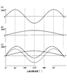
- FIG. 19 shows a waveform (A) in which the magnetic sensor 40 detects the magnetic flux generated by the permanent magnet 9 provided in the main shaft gear 1 when the main shaft gear 1 rotates, and the permanent wave provided in the sub shaft gear 5.
- the vertical axis represents the magnetic flux
- the horizontal axis represents the rotation angle of the main shaft gear 1.
- FIG. 20 shows a waveform (A) in which the magnetic flux generated by the permanent magnet 8 provided in the auxiliary shaft gear 5 is detected by the magnetic sensor 50 when the main shaft gear 1 rotates, and the waveform (A) provided in the main shaft gear 1.
- the waveform (B) in which the magnetic sensor 40 detects the magnetic flux generated by the permanent magnet 9 and the magnetic sensor 50 detects the magnetic flux generated by the permanent magnet 8 It is a figure showing the concept with the magnetic interference waveform (C) at the time of detecting by superposing a part of the generated magnetic flux as a leakage magnetic flux.
- the vertical axis represents the magnetic flux
- the horizontal axis represents the rotation angle of the auxiliary shaft gear 5.
- the main shaft gear 1 and the permanent magnet 9 and the sub shaft gear 5 and the permanent magnet 8 are arranged with a distance from each other with the intermediate gear 2 interposed therebetween. Therefore, it is possible to reduce the occurrence of magnetic interference in which a part of the magnetic flux generated in each of the permanent magnet 8 and the permanent magnet 9 affects the magnetic sensor that does not correspond to each of the permanent magnet 8 and the permanent magnet 9.
- the magnetic sensor 40 originally provided for detecting the change of the magnetic flux generated in the permanent magnet 9 a part of the magnetic flux generated in the permanent magnet 8 provided in the auxiliary shaft gear 5 is used as a leakage magnetic flux. Interference can be reduced.
- the rotation angle or the rotation amount of the auxiliary shaft gear 5 by the magnetic sensor 50 can be reduced while the dimension of the absolute encoder 100 when viewed in plan is relatively reduced. It is possible to prevent a decrease in detection accuracy. Further, according to the absolute encoder 100, it is possible to prevent the detection accuracy of the rotation angle or the rotation amount of the main shaft gear 1 by the magnetic sensor 40 from being lowered while the size of the absolute encoder 100 when viewed in plan is relatively reduced.
- the auxiliary shaft gear 5 is a cylindrical member that is press-fitted and fixed to the shaft portion 6b of the magnet holder 6.
- the sub-shaft gear 5 has a worm wheel portion 5a and a through hole 5b.
- the sub-shaft gear 5 is a member integrally molded of metal or resin, and is formed of polyacetal resin as an example here.
- the worm wheel portion 5a is a gear with which the worm gear portion 2b meshes.
- the worm wheel portion 5a is an example of a second driven gear.
- the worm wheel portion 5a is composed of a plurality of teeth provided on the outer peripheral portion of the cylindrical portion of the countershaft gear 5. In FIG. 4, as the intermediate gear 2 rotates, the rotational force of the intermediate gear 2 is transmitted to the auxiliary shaft gear 5 via the worm gear portion 2b and the worm wheel portion 5a.
- the through hole 5b is a hole penetrating along the central axis of the cylindrical countershaft gear 5.
- the shaft portion 6b of the magnet holder 6 is press-fitted into the through hole 5b, and the auxiliary shaft gear 5 rotates integrally with the magnet holder 6.
- the magnet holder 6 has a magnet holding portion 6a, a shaft portion 6b, and a head 6c.
- the magnet holder 6 is a member integrally molded of metal or resin, and is made of non-magnetic stainless steel as an example here.
- the outer rings 7a of the two bearings 7 are press-fitted into the inner peripheral surface 10dc of the bearing holder portion 10d formed on the main base 10.
- Each of the two bearings 7 has an outer ring 7a and an inner ring 7b.
- the shaft portion 6b of the magnet holder 6 is a cylindrical member, which is press-fitted into the through hole 5b of the auxiliary shaft gear 5, and the lower portion of the shaft portion 6b is inserted into the inner rings 7b of the two bearings 7. Therefore, the magnet holder 6 is axially supported by the main base 10 by the two bearings 7 and rotates integrally with the auxiliary shaft gear 5.
- a head 6c is provided on the upper end of the magnet holder 6.
- the head 6c is a bottomed cylindrical member.
- a magnet holding portion 6a is formed on the head 6c.
- the magnet holding portion 6a is a recess that is recessed downward from the upper end surface of the head 6c.
- the outer peripheral surface of the permanent magnet 8 arranged in the magnet holding portion 6a contacts the inner peripheral surface of the head 6c. As a result, the permanent magnet 8 is fixed to the magnet holding portion 6a of the head 6c.
- the upper portion 10db of the bearing holder portion 10d is an upper region of the bearing holder portion 10d in the Z-axis direction of the entire bearing holder portion 10d.
- One bearing 7 is provided inside the upper portion 10db of the bearing holder portion 10d.
- the lower portion 10da of the bearing holder portion 10d is a lower region of the bearing holder portion 10d in the Z-axis direction of the entire bearing holder portion 10d.
- One bearing 7 is provided inside the lower portion 10da of the bearing holder portion 10d.
- a cutout portion 202a is provided in a part of the housing 202 of the motor 200.
- the cutout portion 202a is a recess that is recessed toward the Z-axis negative direction side. Since the lower portion 10da of the bearing holder portion 10d is provided on the main base 10 in a protruding manner, the notch portion 202a is provided in the housing 202 of the motor 200 to prevent mutual interference.
- the lower portion 10da of the bearing holder portion 10d is a lower region of the bearing holder portion 10d in the Z-axis direction of the entire bearing holder portion 10d.
- One bearing 7 is provided inside the lower portion 10da of the bearing holder portion 10d.
- the upper portion 10db of the bearing holder portion 10d is an upper region of the bearing holder portion 10d in the Z-axis direction in the entire bearing holder portion 10d.
- the bearing 7 is installed at a position closer to the magnet holding portion 6a and the permanent magnet 8 in the axial direction of the shaft portion 6b of the magnet holder 6, it is possible to reduce the axial shake of the magnet holder 6 and the permanent magnet 8 during rotation. ..
- the outer diameter of the upper part 10db of the bearing holder part 10d is close to the intermediate gear 2, forming an inclined surface on the upper part 10db of the bearing holder part 10d avoids interference with the tip circle of the intermediate gear 2.
- the bearing 7 can be installed at a position closer to the magnet holding portion 6a and the permanent magnet 8.
- the magnetic sensor 40 can detect the rotation angle of the corresponding spindle gear 1 by detecting the change in the magnetic flux generated by the permanent magnet 9 due to the rotation of the permanent magnet 9 that rotates together with the spindle gear 1.
- the magnetic sensor 50 can detect the rotation angle of the corresponding auxiliary shaft gear 5 by detecting the change in the magnetic flux generated by the permanent magnet 8 due to the rotation of the permanent magnet 8 rotating with the auxiliary shaft gear 5. ..
- the permanent magnet 8 has a surface 8a.
- the permanent magnet 8 has a substantially cylindrical shape, and the central axis MC1 of the permanent magnet 8 (the axis representing the center of the permanent magnet 8 or the axis passing through the center of the boundary of the magnetic poles) is the central axis HC1 of the magnet holder 6 and the sub-axis. It coincides with the central axis GC1 of the gear 5 and the central axis BC of the bearing 7.
- the surface 8a of the permanent magnet 8 faces the surface 50a of the magnetic sensor 50 at a constant distance.
- the two magnetic poles (N/S) of the permanent magnet 8 are within a plane (XY plane) perpendicular to the central axis MC1 of the permanent magnet 8. It is formed so as to be adjacent to each other. That is, it is desirable that the center of rotation of the permanent magnet 8 and the center of the boundary between the magnetic poles coincide with each other on the central axis MC1. This further improves the detection accuracy of the rotation angle or the rotation amount.
- the permanent magnet 9 is a substantially columnar permanent magnet that is press-fitted into the magnet holding portion 1h of the main shaft gear 1 and has an upper surface 9a and a lower surface 9b.
- the upper surface 9a faces the surface 40a of the magnetic sensor 40 at a constant distance.
- the lower surface 9b is in contact with the bottom surface 1g of the magnet holding portion 1h of the main shaft gear 1, and defines the position of the main shaft gear 1 in the central axis GC2 direction (position in Z axis direction).
- the center axis MC2 of the permanent magnet 9 coincides with the center axis GC2 of the main shaft gear 1 and the center axis RC of the motor shaft 201. ..
- the two magnetic poles (N/S) of the permanent magnet 9 are formed so as to be adjacent to each other within a plane (XY plane) perpendicular to the central axis MC2 of the permanent magnet 9. Is desirable. This further improves the detection accuracy of the rotation angle or the rotation amount.
- Each of the permanent magnets 8 and 9 is made of a magnetic material such as a ferrite-based material or a Nd (neodymium)-Fe (iron)-B (boron)-based material.
- Each of the permanent magnets 8 and 9 may be, for example, a rubber magnet containing a resin binder, a bond magnet, or the like.
- FIG. 13 shows a plurality of through holes formed in the substrate 20, that is, a positioning hole 20a, a positioning hole 20b, a hole 20c, a hole 20d, and a hole 20e.
- the shape of the wall surface forming the positioning hole 20a is, for example, a circle.
- the shape of the wall surface forming the positioning hole 20b is, for example, an ellipse.
- Each of the hole 20c, the hole 20d, and the hole 20e is a through hole for fixing the board 20 to the main base 10 with the board mounting screw 13 shown in FIG.
- the shape of the wall surface forming each of the holes 20c, 20d, and 20e is, for example, a circle.
- the diameter of the wall surface forming each of the hole 20c, the hole 20d, and the hole 20e is larger than the diameter of the male screw portion of the board mounting screw 13 and smaller than the diameter of the head of the board mounting screw 13.
- the main base 10 includes a hole 10a, a hole 10b, an abutment surface 10c, a bearing holder portion 10d, a leaf spring mounting surface 10e, a base portion 60, and a wall portion 70. , The wall 80, the opening 10-1, and the screw hole 10f.
- the main base 10 has a board positioning pin 10g, a board positioning pin 10j, a tip portion 10h, a tip portion 10k, a pillar 10m, a pillar 10q, a pillar 10s, a screw hole 10u, a screw hole 10v, and a screw hole 10w.
- the board positioning pin 10g, the board positioning pin 10j, the pillar 10m, the pillar 10q, and the pillar 10s are examples of pillar members.
- a step portion 10i is formed between the tip portion 10h of the board positioning pin 10g extending from the main base 10 in the Z-axis direction and the base portion 10g1 of the board positioning pin 10g.
- a gap is formed between the lower surface 20-1 of the board 20 and the step portion 10i.
- a step portion 10l is formed between the tip portion 10k of the board positioning pin 10j extending from the main base 10 in the Z-axis direction and the base portion 10j1 of the board positioning pin 10j.
- the base 60 of the main base 10 is, for example, an integrally molded aluminum die-cast member, and is a substantially square plate-shaped member in plan view.
- the base portion 60 is an example of a plate portion.
- the base 60 is attached to the upper surface of the motor 200.
- the opening 10-1 shown in FIG. 3 penetrates the base 60 in the thickness direction (Z-axis direction).
- the main shaft gear 1 is inserted into the opening 10-1.
- the opening 10-1 is an example of a first through hole.
- the wall portion 70 has a wall portion 71 and a wall portion 72.
- the wall portion 70 has a function of supporting the shaft 4 and fixing the leaf spring 11.
- the wall portion 71 is integrally provided on the upper surface of the base portion 60, and extends from the base portion 60 in the Z-axis positive direction.
- the wall portion 70 is provided in a region on the first side 301 side with respect to the center in the X-axis direction and on the fourth side 304 side with respect to the center in the Y-axis direction within the entire upper surface of the base portion 60 in plan view.
- the wall portion 71 has a mounting surface 10ad located on the X axis positive direction side and a screw hole 10ae penetrating in the X axis direction. As shown in FIGS. 1, 14, and 15, the mounting screw 16 is inserted into the hole 15d of the case 15 and is screwed into the screw hole 10ae, so that the mounting surface 10ad of the wall portion 71 is fixed to the mounting surface 10ad of the case 15. The inner surfaces abut and are fixed.
- the wall portion 72 is, in plan view, of the entire upper surface of the base portion 60 on the first side 301 side with respect to the center in the X-axis direction and the third side 303 with respect to the center in the Y-axis direction. It is provided in the side area.
- the wall portion 72 is connected to the wall portion 71 and extends from the wall portion 71 toward the vicinity of the center of the third side 303.
- An end portion of the wall portion 72 on the third side 303 side is connected to the pillar 10s.
- the pillar 10s connected to the wall portion 72 is provided at a position near the center of the main base 10 in the X-axis direction and at a position near the third side 303 of the main base 10. In this way, the wall portion 72 extends from the wall portion 71 toward the pillar 10s. That is, the wall portion 72 extends in an oblique direction with respect to each of the X axis and the Y axis in a plan view.
- the screw 12 is inserted into the hole 11c formed in the mounting portion 11b of the leaf spring 11 and screwed into the screw hole 10f formed in the wall portion 72 of the main base 10.
- the mounting portion 11b of the leaf spring 11 comes into contact with the leaf spring mounting surface 10e formed on the wall portion 72, and the leaf spring 11 is fixed to the wall portion 72.
- the wall portion 72 functions as a fixing portion to which the leaf spring 11 is fixed.
- the sliding portion 11a of the leaf spring 11 contacts the sliding portion 2e of the intermediate gear 2 into which the shaft 4 is inserted.
- the intermediate gear 2 includes one end from the other end 4b of the shaft 4 to one end of the shaft 4.
- the first thrust force is generated in the direction toward 4a or in the direction from one end 4a of the shaft 4 toward the other end 4b of the shaft 4.
- the meshing of the worm gear portion 2b with the worm wheel portion 5a of the auxiliary shaft gear 5 causes the intermediate gear 2 to move in the direction from the other end 4b of the shaft 4 to the one end 4a of the shaft 4 or one end of the shaft 4.
- a second thrust force is generated in a direction from 4a toward the other end 4b of the shaft 4.
- the leaf spring 11 applies a biasing force to the intermediate gear 2 in a direction from one end 4a of the shaft 4 to the other end 4b of the shaft 4.
- the biasing force generated by the leaf spring 11 is set to a value higher than the total force of the first thrust force and the second thrust force in the direction from the other end 4b of the shaft 4 to the one end 4a of the shaft 4. .
- the mounting angle ⁇ is such that the base portion 11d of the leaf spring 11 fixed to the wall portion 72 of the main base 10 and the one end 4a of the shaft 4 are inserted when the intermediate gear 2 is not inserted in the shaft 4.
- the angle is equal to the angle formed by the side surface 73 on the intermediate gear 2 side of the surface of the wall portion 72 where the hole 10a is formed.
- the side surface 73 and the axis 4 are orthogonal to each other in the present embodiment, the angle is not limited to this.
- the mounting angle ⁇ is set such that the sliding portion 11a of the leaf spring 11 comes into contact with the sliding portion 2e of the intermediate gear 2 and the leaf spring 11 bends by a predetermined amount.
- the angle is set so as to appropriately apply the urging force of the shaft 4 in the axial direction Td with respect to 2. Therefore, the leaf spring 11 biases the intermediate gear 2 in the direction from the one end 4a side of the shaft 4 toward the other end 4b side of the shaft 4, so that the direction from the other end 4b of the shaft 4 toward the one end 4a of the shaft 4 is increased.
- the movement of the intermediate gear 2 due to the sum of the first thrust force and the second thrust force is suppressed. As a result, it is possible to prevent the rotation accuracy of the auxiliary shaft gear 5 from decreasing. Note that the greater the biasing force, the greater the sliding resistance when the intermediate gear 2 shown in FIG. 6 rotates.
- the mounting angle ⁇ is set to an appropriate value so that the sliding resistance when the intermediate gear 2 rotates is minimized to the extent that a sufficient biasing force that suppresses the movement of the intermediate gear 2 due to the thrust force is generated. It is desirable to set to. In this way, in order to set the attachment angle ⁇ to an appropriate value, the surface accuracy of the leaf spring attachment surface 10e on which the leaf spring 11 is attached is increased, and the error in the attachment angle of the wall portion 70 to the base portion 60 is reduced. There is a need.
- the main base 10 is formed by aluminum die casting, compared with the case where the individually manufactured base 60 and the wall 70 are combined with each other, for example, by sheet metal, the error in the mounting angle of the wall portion 70 to the base portion 60 can be reduced, and the surface accuracy of the leaf spring mounting surface 10e is increased. As a result, the error in the attachment angle ⁇ of the leaf spring 11 to the wall 72 is reduced, and the urging force is easily managed.
- the main base 10 is fixed by three screws 14 being inserted into three holes formed in the main base 10 and screwed into the screw holes formed in the motor 200.
- a threaded hole 10v, a threaded hole 10u, and a threaded hole 10w are formed on the tip side of the pillar 10q, the pillar 10m, and the pillar 10s extending from the main base 10 in the positive Z-axis direction, respectively.
- Board mounting screws 13 inserted into holes 20c, holes 20e and 20d formed in the substrate 20 shown in FIG. 2 are screwed into the screw holes 10v, 10u and 10w, respectively.
- the upper end surface 10r, the upper end surface 10p, and the upper end surface 10t of each of the pillar 10q, the pillar 10m, and the pillar 10s are in contact with the lower surface 20-1 of the substrate 20 shown in FIG.
- the lower surface 20-1 of the substrate 20 is a surface facing the main base 10 out of the two substrate surfaces of the substrate 20 in the Z-axis direction. As a result, the position of the substrate 20 in the Z-axis direction is defined.
- the case 15 includes an upper surface portion 15-1, a first side surface portion 15A, a second side surface portion 15B, a third side surface portion 15C, and a fourth side surface portion 15D. It is a box-shaped member that is provided and is open on one side.
- the case 15 is made of resin, for example, and is a member integrally molded.
- the upper surface portion 15-1 corresponds to the bottom portion of the box-shaped member.
- the upper surface portion 15-1 is a surface facing the upper surface 20-2 of the substrate 20 shown in FIG.
- the upper surface 20-2 of the substrate 20 is a substrate surface opposite to the lower surface 20-1 side of the substrate 20.
- the first side surface portion 15A is a plate-shaped member extending in the Z-axis negative direction from the side portion of the upper surface portion 15-1 on the X-axis positive direction side.
- the second side surface portion 15B is a plate-shaped member extending in the Z-axis negative direction from the side portion of the upper surface portion 15-1 on the X-axis negative direction side.
- the third side surface portion 15C is a plate-shaped member extending in the Z axis negative direction from the side portion of the upper surface portion 15-1 on the Y axis negative direction side.
- the fourth side surface portion 15D is a plate-shaped member extending in the Z axis negative direction from the side portion of the upper surface portion 15-1 on the Y axis positive direction side.
- the shape of the case 15 in plan view is a rectangular shape corresponding to the shape of the motor 200 in plan view.
- a plurality of components included in the absolute encoder 100 are housed in the space inside the case 15.
- the case 15 has a claw 15a, a claw 15b, a claw 15c, a hole 15d, a recess 15e, a recess 15f, a recess 15g, a connector case 15h, and an opening 15i.
- the tab 15a is provided near the end of the fourth side surface portion 15D in the negative Z-axis direction.
- the claw 15a extends in the Y-axis negative direction from the fourth side surface portion 15D so as to face the third side surface portion 15C.
- the claw 15a is engaged with the recess 10aa provided in the main base 10 shown in FIG.
- the claw 15b is provided near the end of the third side surface portion 15C in the negative Z-axis direction.
- the tab 15b extends from the third side surface portion 15C in the Y-axis positive direction so as to face the fourth side surface portion 15D.
- the claw 15b is engaged with the recess 10ab provided in the main base 10 shown in FIG.
- the tab 15c is provided near the end of the second side surface portion 15B in the negative Z-axis direction.
- the claw 15c extends from the second side surface portion 15B in the X-axis negative direction so as to face the first side surface portion 15A.
- the claw 15c is engaged with the recess 10ac provided in the main base 10 shown in FIG.
- the recesses 15e, 15f, and 15g shown in FIG. It is a recess formed so as to be recessed in the Z-axis positive direction.
- the connector case portion 15h is a recess formed so that a part of the upper surface 5-1 of the case 15 is recessed in the Z-axis positive direction in order to cover the connector 24 shown in FIG.
- the shape of the bottom surface of the connector case portion 15h in a plan view is a rectangle.
- the connector case portion 15h is provided in the upper surface 5-1 in a region closer to the first side surface portion 15A than the center in the X-axis direction and near the center in the Y-axis direction. Further, the connector case portion 15h is provided in a portion near the first side surface portion 15A in the area.
- the opening 15i is formed between the bottom surface of the connector case portion 15h and the first side surface portion 15A.
- the connector 24 shown in FIG. 2 is arranged so as to face the bottom surface of the connector case portion 15h.
- the connector 24 is, for example, a female connector, and a male connector provided at one end of the external wiring is inserted into the connector 24.
- the male connector is inserted into the connector 24 arranged in the connector case portion 15h through the opening 15i shown in FIG.
- the conductive terminal of the male connector provided at one end of the external wiring is electrically connected to the conductive terminal of the connector 24.
- the external device connected to the other end of the external wiring is electrically connected to the connector 24, and the signal can be transmitted between the absolute encoder 100 and the external device.
- the connector case portion 15h is provided at a position closer to the first side surface portion 15A, the position when the connector 24 is viewed in plan is the position of the connector 400 when the motor 200 is viewed in plan, as shown in FIG. Equal to position.
- the absolute encoder 100 By configuring the absolute encoder 100 in this manner, the position where the external wiring electrically connected to the conductive pin provided on the connector 24 is drawn out is electrically connected to the conductive pin provided on the connector 400. It can be brought close to the position where the external wiring is pulled out. Therefore, these external wirings can be bundled into one near the absolute encoder 100 and the motor 200, and the bundled wiring group thus configured can be easily routed to an external device.
- a magnetic sensor 40, a magnetic sensor 50, a microcomputer 21, a bidirectional driver 22, and a line driver 23 are provided on the lower surface 20-1 of the substrate 20.
- the lower surface 20-1 of the substrate 20 is a mounting surface of the magnetic sensor 40 and the magnetic sensor 50.
- the lower surface 20-1 of the substrate 20 is in contact with the upper end surface 10r of the pillar 10q, the upper end surface 10p of the pillar 10m, and the upper end surface 10t of the pillar 10s.
- FIG. 13 a magnetic sensor 40, a magnetic sensor 50, a microcomputer 21, a bidirectional driver 22, and a line driver 23 are provided on the lower surface 20-1 of the substrate 20.
- the lower surface 20-1 of the substrate 20 is a mounting surface of the magnetic sensor 40 and the magnetic sensor 50.
- the lower surface 20-1 of the substrate 20 is in contact with the upper end surface 10r of the pillar 10q, the upper end surface 10p of the pillar 10m, and the upper end surface 10t of the pillar 10s.
- the pillars 10q, the pillars 10m, and the pillars 10s are provided on the main base 10 so that the difference in the distance between the pillars 10q, 10m, and 10s when the main base 10 is viewed in a plan view is small.
- the pillar 10q is provided near the center of the main base 10 in the Y-axis direction near the second side 302.
- the pillar 10q is integrated with the wall 80.
- the pillar 10m is provided near the corner where the first side 301 and the fourth side 304 intersect.
- the pillar 10s is provided near the center of the main base 10 in the X-axis direction near the third side 303.
- the pillar 10s is integrated with the wall portion 70 and the board positioning pin 10g.
- the positions of the magnetic sensor 40 and the magnetic sensor 50 provided on the substrate 20 in the Z-axis direction can be accurately defined. If the pillars 10q, 10m, and 10s are formed as far apart as possible in the XY plane direction on the main base 10, the position of the substrate 20 can be held more stably.
- the main base 10 is formed by die casting. Therefore, for example, the base 60 of the main base 10 is manufactured by sheet metal, and the pillar 10q, the pillar 10m, the pillar 10s, the board positioning pin 10g, the board positioning pin 10j, the wall portion 70, the wall portion 80, and the like are individually manufactured and assembled. As compared with the case, the positional accuracy between each component is improved. Further, since the number of parts at the time of manufacturing is reduced, the structure of the absolute encoder 100 can be simplified, the assembly can be facilitated, the manufacturing time can be shortened, and the reliability of the absolute encoder 100 can be improved.
- the magnetic sensor 40 is an example of a spindle angle sensor.
- the magnetic sensor 40 is arranged directly above the permanent magnet 9 with a predetermined gap.
- the magnetic sensor 40 detects and specifies the rotation angle of the corresponding spindle gear 1 by detecting the change in the magnetic flux generated from the permanent magnet 9 due to the rotation of the permanent magnet 9 that rotates together with the spindle gear 1, and the specified rotation angle. Is output as a digital signal.
- the magnetic sensor 50 is an example of an angle sensor.
- the auxiliary shaft gear 5 is a rotating body that rotates in accordance with the rotation of the worm wheel portion 5a that is the second driven gear.
- the magnetic sensor 50 is arranged directly above the permanent magnet 8 with a predetermined gap.
- the magnetic sensor 50 detects and specifies the rotation angle of the corresponding auxiliary shaft gear 5 by detecting the change in the magnetic flux generated from the permanent magnet 8 due to the rotation of the permanent magnet 8 that rotates together with the auxiliary shaft gear 5.
- the angle information indicating the rotation angle is output as a digital signal.
- Each of the magnetic sensor 40 and the magnetic sensor 50 includes, for example, a detection element that detects a change in magnetic flux, and an arithmetic circuit that outputs a digital signal indicating a rotation angle based on the output of the detection element.
- the sensing element may be a combination of a plurality of magnetic field sensing elements such as Hall elements and GMR (Giant Magneto Resistive) elements.
- the number of magnetic field sensing elements is, for example, four.
- the reduction ratio is 5. That is, when the main shaft gear 1 makes five revolutions, the intermediate gear 2 makes one revolution.
- the main shaft gear 1 and the sub shaft gear 5 are provided with permanent magnets 9 and 8 that rotate integrally. Therefore, the magnetic sensor 40 and the magnetic sensor 50 corresponding to each can identify the rotation amount of the motor shaft 201 by detecting the rotation angle of the main shaft gear 1 and the sub shaft gear 5.
- the main shaft gear 1 rotates once, the sub shaft gear 5 rotates 1/90, that is, 4 degrees. Therefore, when the rotation angle of the auxiliary shaft gear 5 is less than 4 degrees, the rotation amount of the main shaft gear 1 is less than one rotation, and when the rotation angle of the auxiliary shaft gear 5 is 4 degrees or more and less than 8 degrees, the main shaft gear 1 is rotated.
- the rotation amount of is 1 rotation or more and less than 2 rotations.
- the rotation speed of the main shaft gear 1 can be specified according to the rotation angle of the sub shaft gear 5.
- the absolute encoder 100 uses the reduction ratio between the worm gear portion 1d and the worm wheel portion 2a and the reduction ratio between the worm gear portion 2b and the worm wheel portion 5a, so that the spindle gear 1 rotates at a plurality of revolutions.
- the rotation speed of the main shaft gear 1 can be specified.
- the microcomputer 21, the bidirectional driver 22, the line driver 23, and the connector 24 are mounted on the board 20.
- the microcomputer 21, the bidirectional driver 22, the line driver 23, and the connector 24 are electrically connected by pattern wiring on the substrate 20.
- the microcomputer 21 is composed of a CPU (Central Processing Unit), acquires a digital signal representing the rotation angle output from each of the magnetic sensor 40 and the magnetic sensor 50, and calculates the rotation amount of the spindle gear 1. To do.
- CPU Central Processing Unit
- the bidirectional driver 22 performs bidirectional communication with an external device connected to the connector 24.
- the bidirectional driver 22 converts data such as an operation signal into a differential signal and communicates with an external device.
- the line driver 23 converts the data representing the rotation amount into a differential signal and outputs the differential signal to an external device connected to the connector 24 in real time.
- a connector of an external device is connected to the connector 24.
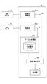
- FIG. 21 is a diagram showing a functional configuration of the microcomputer 21. Each block of the microcomputer 21 shown in FIG. 21 represents a function realized by the CPU as the microcomputer 21 executing a program.
- the microcomputer 21 includes a rotation angle acquisition unit 21p, a rotation angle acquisition unit 21q, a table processing unit 21b, a rotation amount identification unit 21c, and an output unit 21e.
- the rotation angle acquisition unit 21q acquires the rotation angle Aq of the spindle gear 1 based on the signal output from the magnetic sensor 40.
- the rotation angle Aq is angle information indicating the rotation angle of the main shaft gear 1.
- the rotation angle acquisition unit 21p acquires the rotation angle Ap of the auxiliary shaft gear 5 based on the signal output from the magnetic sensor 50.
- the rotation angle Ap is angle information indicating the rotation angle of the sub shaft gear 5.
- the table processing unit 21b refers to the correspondence table that stores the rotation angle Ap and the rotation speed of the spindle gear 1 corresponding to the rotation angle Ap, and refers to the acquired rotation speed of the spindle gear 1 corresponding to the rotation angle Ap. Identify.
- the rotation amount specifying unit 21c specifies the rotation amount of the main shaft gear 1 over a plurality of rotations according to the rotation speed of the main shaft gear 1 specified by the table processing unit 21b and the acquired rotation angle Aq.
- the output unit 21e converts the specified rotation amount of the main shaft gear 1 over a plurality of rotations into information indicating the rotation amount and outputs the information.
- the auxiliary shaft gear 5 is provided on the opposite side of the intermediate gear 2 from the main shaft gear 1 side. It is possible to reduce the occurrence of magnetic interference that affects magnetic sensors that do not correspond to the permanent magnets 8 and 9, respectively.
- the absolute encoder 100 can reduce the size of the absolute encoder 100 in a plan view by adopting the structure capable of reducing the occurrence of magnetic interference. Therefore, while reducing the size of the absolute encoder 100, it is possible to prevent the magnetic sensor 40 and the magnetic sensor 50 from decreasing the detection accuracy of the magnetic flux.
- the intermediate gear 2 arranged in parallel with the upper surface of the main base 10 extends obliquely with respect to the four sides of the main base 10, and further the main shaft with respect to the intermediate gear 2.
- the gear 1 and the countershaft gear 5 are provided on the opposite sides of the intermediate gear 2.
- the main shaft gear 1, the intermediate gear 2, and the auxiliary shaft gear 5 can be arranged in a narrow region of a part of the entire upper surface of the main base 10, and the size of the absolute encoder 100 in the horizontal direction can be reduced.
- the outer diameter of the worm wheel portion 2a and the outer diameter of the worm gear portion 2b are set to the smallest possible values. This makes it possible to reduce the size of the absolute encoder 100 in the Z-axis direction (height direction).
- the dimension in the Z-axis direction and the dimension in the direction orthogonal to the Z-axis direction are prevented while preventing a decrease in detection accuracy of the rotation amount of the main shaft gear 1. It has the effect of being small.
- the intermediate gear 2 is axially supported, that is, rotatably supported with respect to the shaft 4 fixed or inserted in each of the wall portion 80 and the wall portion 72.
- the method of supporting the intermediate gear 2 is not limited to this.
- the absolute encoder 100 is configured such that one end 4a of the shaft 4 is inserted into the hole 10a formed in the wall 72, and the other end 4b of the shaft 4 is fixed by press fitting into the hole 10b formed in the wall 80.
- the absolute encoder 100 may be configured such that the outer ring 3a of the bearing 3 is press-fitted and fixed to the press-fitting portion 2d formed in the intermediate gear 2, and the shaft 4 is press-fitted and fixed to the inner ring 3b of the bearing 3. .. This limits the movement of the intermediate gear 2 fixed to the shaft 4 in the axial direction Td. Even when the absolute encoder 100 is configured as described above, the intermediate gear 2 is rotatably supported by the shaft 4.
- the movement of the shaft 4 in the axial direction Td is limited by the wall portion 72 and the wall portion 80, and the movement of the intermediate gear 2 in the axial direction Td is also limited by the inner ring 3b of the bearing 3 fixed to the shaft 4. It Therefore, the leaf spring 11 becomes unnecessary.
- the absolute encoder 100 is provided on at least one of the wall portion 72 and the wall portion 80 in a state where the intermediate gear 2 is fixed to the shaft 4 without using the bearing 3 shown in FIG.
- the shaft 4 may be rotatably supported by the bearing.
- the intermediate gear 2 is fixed to the shaft 4 and the shaft 4 is not shown. Since the bearing is rotatably supported by the bearing, the shaft 4 and the intermediate gear 2 can rotate integrally. In this case, the shaft 4 is not fixed to the inner ring of the bearing but is only inserted into the inner ring, so that the shaft 4 can move in the axial direction Td together with the intermediate gear 2. Therefore, the leaf spring 11 for urging the intermediate gear 2 in the axial direction Td and defining the position is required.
- the outer ring of the bearing (not shown) may be fixed to the wall portion 72 or the wall portion 80, and one end 4a or the other end 4b of the shaft 4 may be press-fitted into the inner ring (not shown).
- the movement of the intermediate gear 2 fixed to the shaft 4 in the axial direction Td is restricted. Therefore, not only the intermediate gear 2 fixed to the shaft 4 is rotatably supported by a bearing (not shown), but also the movement of the shaft 4 in the axial direction Td is limited, so that the intermediate gear 2 in the axial direction Td is restricted. Movement is also restricted. Therefore, the leaf spring 11 becomes unnecessary.
- the diameter D of the worm wheel portion 2a that is the first driven gear is equal to or less than the axial height H of the worm gear portion 1d that is the first drive gear.
- 1 spindle gear 1a first tubular portion, 1b second tubular portion, 1c communicating portion, 1d worm gear portion, 1e bottom surface, 1f press-fitting portion, 1g bottom surface, 1h magnet holding portion, 2 intermediate gear, 2a worm wheel portion, 2b Worm gear part, 2c bearing part, 2d press fit part, 2e sliding part, 2f bottom face, 2g through hole, 3 bearing, 3a outer ring, 3b inner ring, 3c side face, 3d side face, 4 axis, 4a one end, 4b other end, 5 Secondary shaft gear, 5-1 upper surface, 5a worm wheel section, 5b through hole, 6 magnet holder, 6a magnet holding section, 6b shaft section, 6c head, 7 bearing, 7a outer ring, 7b inner ring, 8 permanent magnet, 8a surface, 9 permanent magnet, 9a upper surface, 9b lower surface, 10 main base, 10-1 opening, 10-2 lower surface, 10a hole, 10aa, 10ab, 10ac recess, 10ad mounting
Priority Applications (2)
| Application Number | Priority Date | Filing Date | Title |
|---|---|---|---|
| US17/295,201 US11561117B2 (en) | 2018-11-30 | 2019-11-21 | Absolute encoder for detecting rotation angle |
| CN201980078235.3A CN113167602B (zh) | 2018-11-30 | 2019-11-21 | 绝对编码器 |
Applications Claiming Priority (2)
| Application Number | Priority Date | Filing Date | Title |
|---|---|---|---|
| JP2018225877A JP7137449B2 (ja) | 2018-11-30 | 2018-11-30 | アブソリュートエンコーダ |
| JP2018-225877 | 2018-11-30 |
Publications (1)
| Publication Number | Publication Date |
|---|---|
| WO2020110901A1 true WO2020110901A1 (ja) | 2020-06-04 |
Family
ID=70852982
Family Applications (1)
| Application Number | Title | Priority Date | Filing Date |
|---|---|---|---|
| PCT/JP2019/045610 WO2020110901A1 (ja) | 2018-11-30 | 2019-11-21 | アブソリュートエンコーダ |
Country Status (5)
| Country | Link |
|---|---|
| US (1) | US11561117B2 (zh) |
| JP (1) | JP7137449B2 (zh) |
| CN (1) | CN113167602B (zh) |
| TW (1) | TWI796532B (zh) |
| WO (1) | WO2020110901A1 (zh) |
Families Citing this family (3)
| Publication number | Priority date | Publication date | Assignee | Title |
|---|---|---|---|---|
| JP7316075B2 (ja) * | 2019-03-28 | 2023-07-27 | ミネベアミツミ株式会社 | アブソリュートエンコーダ |
| JP7441061B2 (ja) * | 2020-01-31 | 2024-02-29 | ミネベアミツミ株式会社 | アブソリュートエンコーダ、アブソリュートエンコーダの角度誤差情報出力プログラム、アブソリュートエンコーダの角度誤差情報出力方法 |
| KR20230084877A (ko) * | 2021-12-06 | 2023-06-13 | 삼성전기주식회사 | 회전체 감지 장치 |
Citations (5)
| Publication number | Priority date | Publication date | Assignee | Title |
|---|---|---|---|---|
| JPH09291982A (ja) * | 1996-04-24 | 1997-11-11 | Matsushita Electric Ind Co Ltd | バックラッシュ除去装置 |
| JP2004077483A (ja) * | 2002-08-19 | 2004-03-11 | Stegmann Gmbh & Co Kg | マルチターン・角度測定器 |
| US20110247440A1 (en) * | 2008-10-31 | 2011-10-13 | William Lyle Warke | Worm gear clutch mechanism |
| JP2013002571A (ja) * | 2011-06-17 | 2013-01-07 | Ricoh Co Ltd | 駆動装置及びこれを備えた画像形成装置 |
| JP2018087774A (ja) * | 2016-11-29 | 2018-06-07 | ミネベアミツミ株式会社 | アブソリュートエンコーダ、回転量を特定する方法 |
Family Cites Families (13)
| Publication number | Priority date | Publication date | Assignee | Title |
|---|---|---|---|---|
| JPH0496019U (zh) | 1991-01-14 | 1992-08-20 | ||
| DE19855960A1 (de) * | 1998-12-04 | 2000-06-08 | Bosch Gmbh Robert | Vorrichtung und Verfahren zur Messung der Winkellage eines drehbaren Körpers |
| JP3920113B2 (ja) * | 2002-03-05 | 2007-05-30 | アルプス電気株式会社 | 回転角検出装置 |
| US7922181B2 (en) * | 2006-03-09 | 2011-04-12 | Honda Motor Co., Ltd. | Vehicle height adjusting system |
| JP2007298291A (ja) * | 2006-04-27 | 2007-11-15 | Tokai Rika Co Ltd | 回転角度検出装置 |
| US7841231B2 (en) * | 2006-07-25 | 2010-11-30 | Lg Innotek Co., Ltd. | Steering angle sensing apparatus and method thereof |
| JP2008202762A (ja) * | 2007-02-22 | 2008-09-04 | Aisin Ai Co Ltd | 磁気センサ装置を備えた変速機 |
| KR101333604B1 (ko) | 2007-04-19 | 2013-11-28 | 고쿠사이 게이소쿠키 가부시키가이샤 | 만능 시험 장치, 직동 액추에이터, 및 비틀림 시험 장치 |
| JP5256174B2 (ja) * | 2009-11-19 | 2013-08-07 | 山洋電気株式会社 | 磁気式アブソリュートエンコーダ |
| JP6050649B2 (ja) * | 2012-10-22 | 2016-12-21 | 日本電産サンキョー株式会社 | ギアードモータ |
| JP5862616B2 (ja) | 2013-07-17 | 2016-02-16 | ウシオ電機株式会社 | 光配向用偏光光照射装置及び光配向用偏光光照射方法 |
| JP5701351B2 (ja) * | 2013-09-03 | 2015-04-15 | 株式会社ツバキE&M | 直交型ギアモータ |
| US10415670B2 (en) * | 2017-05-09 | 2019-09-17 | Astronova, Inc. | Worm drive |
-
2018
- 2018-11-30 JP JP2018225877A patent/JP7137449B2/ja active Active
-
2019
- 2019-11-21 WO PCT/JP2019/045610 patent/WO2020110901A1/ja active Application Filing
- 2019-11-21 US US17/295,201 patent/US11561117B2/en active Active
- 2019-11-21 CN CN201980078235.3A patent/CN113167602B/zh active Active
- 2019-11-27 TW TW108143080A patent/TWI796532B/zh active
Patent Citations (5)
| Publication number | Priority date | Publication date | Assignee | Title |
|---|---|---|---|---|
| JPH09291982A (ja) * | 1996-04-24 | 1997-11-11 | Matsushita Electric Ind Co Ltd | バックラッシュ除去装置 |
| JP2004077483A (ja) * | 2002-08-19 | 2004-03-11 | Stegmann Gmbh & Co Kg | マルチターン・角度測定器 |
| US20110247440A1 (en) * | 2008-10-31 | 2011-10-13 | William Lyle Warke | Worm gear clutch mechanism |
| JP2013002571A (ja) * | 2011-06-17 | 2013-01-07 | Ricoh Co Ltd | 駆動装置及びこれを備えた画像形成装置 |
| JP2018087774A (ja) * | 2016-11-29 | 2018-06-07 | ミネベアミツミ株式会社 | アブソリュートエンコーダ、回転量を特定する方法 |
Also Published As
| Publication number | Publication date |
|---|---|
| CN113167602B (zh) | 2023-08-15 |
| JP2020085866A (ja) | 2020-06-04 |
| TW202028700A (zh) | 2020-08-01 |
| US11561117B2 (en) | 2023-01-24 |
| TWI796532B (zh) | 2023-03-21 |
| JP7137449B2 (ja) | 2022-09-14 |
| CN113167602A (zh) | 2021-07-23 |
| US20220018690A1 (en) | 2022-01-20 |
Similar Documents
| Publication | Publication Date | Title |
|---|---|---|
| CN110869708B (zh) | 绝对编码器 | |
| WO2020203466A1 (ja) | 減速機構及びアブソリュートエンコーダ | |
| WO2020110901A1 (ja) | アブソリュートエンコーダ | |
| JP7316077B2 (ja) | アブソリュートエンコーダ | |
| JP2023133628A (ja) | アブソリュートエンコーダ | |
| JP2024026598A (ja) | アブソリュートエンコーダ | |
| WO2020203199A1 (ja) | アブソリュートエンコーダ | |
| JP7277190B2 (ja) | アブソリュートエンコーダ | |
| WO2020196533A1 (ja) | アブソリュートエンコーダ | |
| CN116964417A (zh) | 绝对编码器 | |
| JP7303655B2 (ja) | アブソリュートエンコーダ | |
| JP7202239B2 (ja) | アブソリュートエンコーダ | |
| JP4460048B2 (ja) | 磁気式エンコーダ | |
| JP2008111808A (ja) | トルク検知センサ | |
| JP2009276241A (ja) | 回転角検出装置 |
Legal Events
| Date | Code | Title | Description |
|---|---|---|---|
| 121 | Ep: the epo has been informed by wipo that ep was designated in this application |
Ref document number: 19891217 Country of ref document: EP Kind code of ref document: A1 |
|
| NENP | Non-entry into the national phase |
Ref country code: DE |
|
| 122 | Ep: pct application non-entry in european phase |
Ref document number: 19891217 Country of ref document: EP Kind code of ref document: A1 |