WO2020110539A1 - 打撃作業機 - Google Patents
打撃作業機 Download PDFInfo
- Publication number
- WO2020110539A1 WO2020110539A1 PCT/JP2019/041959 JP2019041959W WO2020110539A1 WO 2020110539 A1 WO2020110539 A1 WO 2020110539A1 JP 2019041959 W JP2019041959 W JP 2019041959W WO 2020110539 A1 WO2020110539 A1 WO 2020110539A1
- Authority
- WO
- WIPO (PCT)
- Prior art keywords
- sleeve
- gear
- clutch member
- shaft
- intermediate shaft
- Prior art date
- Legal status (The legal status is an assumption and is not a legal conclusion. Google has not performed a legal analysis and makes no representation as to the accuracy of the status listed.)
- Ceased
Links
Images



Classifications
-
- B—PERFORMING OPERATIONS; TRANSPORTING
- B25—HAND TOOLS; PORTABLE POWER-DRIVEN TOOLS; MANIPULATORS
- B25D—PERCUSSIVE TOOLS
- B25D16/00—Portable percussive machines with superimposed rotation, the rotational movement of the output shaft of a motor being modified to generate axial impacts on the tool bit
- B25D16/006—Mode changers; Mechanisms connected thereto
-
- B—PERFORMING OPERATIONS; TRANSPORTING
- B25—HAND TOOLS; PORTABLE POWER-DRIVEN TOOLS; MANIPULATORS
- B25D—PERCUSSIVE TOOLS
- B25D2211/00—Details of portable percussive tools with electromotor or other motor drive
- B25D2211/06—Means for driving the impulse member
- B25D2211/061—Swash-plate actuated impulse-driving mechanisms
-
- B—PERFORMING OPERATIONS; TRANSPORTING
- B25—HAND TOOLS; PORTABLE POWER-DRIVEN TOOLS; MANIPULATORS
- B25D—PERCUSSIVE TOOLS
- B25D2250/00—General details of portable percussive tools; Components used in portable percussive tools
- B25D2250/231—Sleeve details
- B25D2250/235—Sleeve couplings
Definitions
- the present invention relates to a striking work machine including a tip tool to which one or both of a striking force and a rotating force are applied.
- a percussion work machine having a plurality of switchable operation modes is known.
- the operation modes of the conventional striking work machine include, for example, “rotation mode”, “striking mode”, and “rotation-striking mode”.
- the “rotation mode” is an operation mode in which a turning force is applied to the tip tool, and is sometimes called a “drill mode”.
- the “striking mode” is an operation mode in which a striking force is applied to the tip tool, and is sometimes called a “hammer mode”.
- the “rotation-striking mode” is an operation mode in which a striking force and a rotating force are applied to the tip tool, and is sometimes called a “hammer drill mode”.
- a conventional percussion work machine is provided with a rotary shaft that is rotationally driven by a driving force output from a drive source, and a state in which the rotation of the rotary shaft is transmitted to a tip tool and the rotation of the rotary shaft is the tip. It is possible to switch between the state where it is not transmitted to the tool.
- the gear and the connecting member are arranged on the rotating shaft. The connecting member is constantly engaged with the rotating shaft and rotates integrally with the rotating shaft. On the other hand, the gear is not engaged with the rotation shaft and is movable along the rotation shaft.
- the larger the number of parts constituting the power transmission system the more complicated the structure and the more man-hours for assembling.
- the increase in the number of parts of the power transmission system causes the impact working machine including the power transmission system to become large in size, high in cost, and increase in weight, which is one of the causes of lowering the operability of the impact working machine.
- An object of the present invention is to suppress the cost increase of a percussion work machine having a plurality of operation modes and to improve the operability.
- a percussion work machine of the present invention includes a drive source, a tip tool arranged in front of the drive source, to which one or both of a percussion force and a rotational force are applied, and a center axis extending in the front-rear direction as a center.
- a rotary shaft that is driven to rotate by a power source; and a rotary force transmission system that transmits the rotary force of the rotary shaft to the tip tool.
- the rotary force transmission system is movable in the front-rear direction on the rotary shaft. Including a sleeve provided on the.
- FIG. 9 is a partial cross-sectional view showing the positions of the clutch member and the sleeve when the hammer mode is selected. It is an exploded perspective view showing the components of the operating mechanism.
- the percussion work machine according to the present embodiment is a hammer drill having a plurality of switchable operation modes.
- the operation modes of the hammer drill according to the present embodiment include at least three operation modes of “rotation mode (drill mode)”, “striking mode (hammer mode)” and “hammer drill mode (rotation-striking mode)”. ..
- the drill mode is selected, the turning force is applied to the tip tool, and when the hammer mode is selected, the impact force is applied to the tip tool. Further, when the hammer drill mode is selected, both the rotational force and the striking force are applied to the tip tool.
- a drill bit is an example of a tip tool that is attached to a hammer drill and is provided with one or both of a striking force and a rotating force.
- the drill bit is used, for example, when making a hole in concrete or stone.
- the tip tool attached to the hammer drill is not limited to the drill bit, and may be replaced as appropriate according to the type of object or work on the object.
- a hammer drill 1A As shown in FIG. 1, a hammer drill 1A according to the present embodiment has a housing 10, a handle 11 provided on one end side of the housing 10, and a sub-handle provided on the other end side of the housing 10. 12 and.
- a motor 20 that is a drive source of the tip tool 2
- an impact force transmission system 30 that converts a driving force (rotational force) output from the motor 20 into an impact force and transmits the impact force to the tip tool 2
- a rotational force transmission system 40 that transmits the driving force (rotational force) output from the motor 20 to the tip tool 2 is provided.
- the striking force transmission system 30 and the rotational force transmission system 40 may be collectively referred to as a “power transmission system”.
- the motor 20 has a stator, a rotor and an output shaft 21.
- the output shaft 21 extends through the rotor in the longitudinal direction of the housing 10.
- the longitudinal direction of the housing 10, that is, the direction of the output shaft 21 is defined as the front-back direction.
- the side on which the sub handle 12 is provided is defined as “front” and the side on which the handle 11 is provided is defined as “rear”.
- the tip tool 2 is arranged in front of the motor 20 that is the drive source.
- the output shaft 21 that extends through the rotor in the front-rear direction is rotatably supported by two bearings 22a and 22b.
- the bearing 22a rotatably supports the front side (tip side) of the output shaft 21, and the bearing 22b rotatably supports the rear side (rear end side) of the output shaft 21.
- the tip end side of the output shaft 21 penetrates the bearing 22a and projects to the front of the bearing 22a.
- a gear (pinion 23) is provided at the tip of the output shaft 21 projecting forward of the bearing 22a.
- the motor 20 operates based on the operation of the trigger 11a provided on the handle 11. Specifically, when the operator pulls the trigger 11a, electric power is supplied to the motor 20 and the output shaft 21 rotates. On the other hand, when the operator pulls the trigger 11a, the power supply to the motor 20 is cut off and the output shaft 21 stops rotating.
- a cooling fan 24 is attached to the output shaft 21. The cooling fan 24 rotates integrally with the output shaft 21, and mainly generates cooling air for cooling the motor 20.
- a drive circuit including switching elements, a control circuit including Hall elements, and the like are arranged around the motor 20, and these circuits are also cooled by the cooling air generated by the cooling fan 24.
- a rotary shaft 25 and a cylinder 31 are arranged in the housing 10 in parallel with the output shaft 21.
- the tip end side of the rotary shaft 25 is rotatably supported by a bearing 25a, and the rear end side of the rotary shaft 25 is rotatably supported by a bearing 25b.
- a driven gear 26 that engages with a pinion 23 provided at the tip of the output shaft 21 is provided at the rear end of the rotary shaft 25 that penetrates the bearing 25b and projects to the rear of the bearing 25b.
- a conversion mechanism 32 for converting the rotational motion of the intermediate shaft 25 into a reciprocating motion is provided on the intermediate shaft 25 and in front of the bearing 25b.
- the conversion mechanism 32 includes an inner ring, an outer ring, rolling elements, and a connecting rod, and is sometimes called a "reciprocating bearing".
- the inner ring is supported so as to be rotatable relative to the intermediate shaft 25, the outer ring is arranged around the inner ring, and the rolling elements are interposed between the inner ring and the outer ring.
- the connecting rod extends from the outer peripheral surface of the outer ring toward the radially outer side of the outer ring.
- Grooves having an arcuate cross section are formed on the outer peripheral surface of the inner ring and the inner peripheral surface of the outer ring, respectively.
- the rolling element is interposed between the inner ring and the outer ring in a state where a part of the rolling element is fitted in the groove formed in the inner ring and the other part is fitted in the groove formed in the outer ring.
- the inner ring and the outer ring are relatively rotatably connected to each other via the rolling elements.
- a clutch member 33 that is movable back and forth along the intermediate shaft 25 is provided. While the clutch member 33 is always engaged with the intermediate shaft 25, the clutch member 33 has an engagement position where the rotation of the intermediate shaft 25 is transmitted to the conversion mechanism 32, and a non-engagement position where the rotation of the intermediate shaft 25 is not transmitted to the conversion mechanism 32. You can move to and.
- the intermediate shaft 25 and the conversion mechanism 32 are connected via the clutch member 33, and the power is transmitted from the intermediate shaft 25 to the conversion mechanism 32.
- a pawl provided on the rear end of the clutch member 33 that rotates integrally with the intermediate shaft 25 engages with a pawl provided on the front end of the inner ring of the conversion mechanism 32, and the rotation of the intermediate shaft 25 is changed to the clutch. It is transmitted to the inner ring via the member 33.
- the connecting rod swinging as described above is rotatably connected to the back surface of the cup-shaped piston 34 housed in the cylinder 31.
- the cylinder 31 accommodates a hitting element 35 and an intermediate element 36.
- the piston 34, the striker 35, and the intermediate 36 are arranged in a line in this order from the rear to the front, and an air chamber 37 is provided between the piston 34 and the striker 35.
- a retainer sleeve 38 as a holding portion is provided in front of the cylinder 31.
- the retainer sleeve 38 is integrally formed on the tip end side of the cylinder 31, and the cylinder 31 and the retainer sleeve 38 are connected so as not to rotate relative to each other.
- the root portion of the tip tool 2 is inserted into the retainer sleeve 38, and the retainer sleeve 38 holds the inserted root portion of the tip tool 2 so as to be linearly movable within a predetermined range.
- the piston 34 reciprocates back and forth within the cylinder 31.
- the connecting rod swings back and forth when the intermediate shaft 25 rotates while the clutch member 33 is at the engagement position. That is, the conversion mechanism 32 converts the rotational movement of the intermediate shaft 25 into the reciprocating movement of the piston 34.
- the intermediate shaft 25 is rotationally driven by the motor 20 about the central axis extending in the front-rear direction.
- the rotational force of the intermediate shaft 25 is struck by a striking force transmission system 30 including a cylinder 31, a conversion mechanism 32, a clutch member 33, a piston 34, a striking element 35, an intermediate element 36, an air chamber 37 and a retainer sleeve 38. It is converted into force and transmitted to the tip tool 2.
- a sleeve 41 that is movable back and forth along the intermediate shaft 25 is provided on the intermediate shaft 25 and in front of the clutch member 33. More specifically, the sleeve 41 is arranged between the clutch member 33 and the bearing 25a.
- the conversion mechanism 32 is arranged in front of the bearing 25b, and the clutch member 33 is arranged in front of the conversion mechanism 32. That is, the conversion mechanism 32, the clutch member 33, and the sleeve 41 are arranged in this order from the rear to the front, and are arranged between the two bearings 25b and 25a.
- the intermediate shaft 25 penetrates the conversion mechanism 32, the clutch member 33, and the sleeve 41 in this order.
- an inner gear 42 is formed on the inner peripheral surface of the sleeve 41, and an outer gear 43 is formed on the outer peripheral surface of the sleeve 41.
- an intermediate gear 27 engageable with the inner gear 42 is formed integrally with the intermediate shaft 25.
- the clutch member 33 that engages with the intermediate shaft 25 so as to be able to transmit power at both the engaged position and the disengaged position is the same as the intermediate gear 27 with the gear 28 formed on the outer peripheral surface of the intermediate shaft 25.
- the gear 28 is formed on the outer peripheral surface of the intermediate shaft 25 at the same time as the intermediate gear 27.
- the gear is divided into front and rear parts, a part of which is an intermediate gear 27, and the other part of which is a gear 28 which is constantly engaged with the clutch member 33. It was done.
- the manufacturing cost of the intermediate shaft 25 can be reduced.
- the position of the sleeve 41 shown in FIG. 2B (the position at which the sleeve 41 and the intermediate shaft 25 are engaged and the rotational force can be transmitted to the tip tool 2 (FIG. 1)) will be described. It may be called a "connection position”. Further, the position of the sleeve 41 shown in FIG. 2A (the position where the engagement between the sleeve 41 and the intermediate shaft 25 is released and the rotational force cannot be transmitted to the tip tool 2 (FIG. 1)) is set to " It may be referred to as "non-coupling position".
- annular groove 44 for accommodating the intermediate gear 27 when the sleeve 41 moves to the non-coupling position is formed inside the sleeve 41.
- the sleeve 41 is retracted to the non-coupling position, and the intermediate gear 27 is housed (released) in the annular groove 44, whereby the engagement between the sleeve 41 and the intermediate shaft 25 is released.
- the annular groove 44 accommodates the intermediate gear 27 without engaging with the intermediate gear 27.
- a cylinder gear 45 that engages with an outer gear 43 formed on the sleeve 41 is formed around the cylinder 31.
- the cylinder gear 45 is a ring-shaped gear formed over the entire circumference of the cylinder 31, and is spline-coupled to the outer gear 43. Therefore, when the sleeve 41 moves to the coupling position and the sleeve 41 and the intermediate shaft 25 engage with each other for power transmission, the rotational force of the intermediate shaft 25 is transmitted to the cylinder 31 via the outer gear 43 and the cylinder gear 45. The cylinder 31 rotates. Then, the rotational force is transmitted to the tip tool 2 connected to the cylinder 31 via the retainer sleeve 38.
- the intermediate shaft 25 is rotationally driven by the motor 20 about the central axis extending in the front-rear direction. Then, the rotational force of the intermediate shaft 25 is transmitted to the tip tool 2 by the rotational force transmission system 40 including the sleeve 41 (inner gear 42 and outer gear 43), the cylinder 31 (cylinder gear 45), the retainer sleeve 38, and the like. ..
- FIG. 3 shows the positions of the clutch member 33 and the sleeve 41 in each operation mode.
- FIG. 3A shows the positions of the clutch member 33 and the sleeve 41 when the drill mode is selected.
- FIG. 3B shows the positions of the clutch member 33 and the sleeve 41 when the hammer drill mode is selected.
- FIG. 3C shows the positions of the clutch member 33 and the sleeve 41 when the hammer mode is selected.
- an elastic body 70 is provided around the intermediate shaft 25 and between the clutch member 33 and the sleeve 41 so as to urge the clutch member 33 and the sleeve 41 away from each other. ..
- the elastic body 70 in the present embodiment is a coil spring wound around the intermediate shaft 25.
- the coil spring 70 is arranged between the clutch member 33 and the sleeve 41 in a compressed state. Therefore, the coil spring 70 constantly urges the clutch member 33 rearward and always urges the sleeve 41 forward.
- the clutch member 33 advances to the non-engagement position against the bias of the coil spring 70, and the sleeve 41.
- the position of does not change. That is, the clutch member 33 moves to the disengaged position, while the sleeve 41 stays at the connected position.
- the impact force is not applied to the tip tool 2 shown in FIG. 1, but only the rotational force is applied.
- the hammer drill 1A shown in FIG. 1 is provided with an operating mechanism for moving the clutch member 33 and the sleeve 41 to switch the operation mode.
- the operation mechanism is composed of the operation unit 50 and the slider 60 shown in FIG.
- the operation unit 50 is provided on the side surface of the housing 10 (FIG. 1) and is operated by an operator.
- the slider 60 is provided inside the housing 10 (FIG. 1 ), moves along with the operation of the operation unit 50, and moves the clutch member 33 and the sleeve 41 back and forth. Specifically, the operation unit 50 is rotated by the operator, and the slider 60 slides back and forth on the intermediate shaft 25 as the operation unit 50 rotates. Therefore, in the following description, the operation unit 50 may be referred to as the “dial 50”.
- the dial 50 shown in FIG. 4 is rotatably supported by the housing 10 (FIG. 1) by a support shaft (not shown).
- a knob 51 is formed on the front surface of the dial 50, and a movable member 52 is projectingly provided on the back surface of the dial 50.
- the movable member 52 is provided at a position displaced radially outward from the center of rotation of the dial 50. That is, the movable member 52 is eccentric with respect to the rotation center of the dial 50, and moves in the front-back direction as the dial 50 rotates. That is, the movable member 52 in the present embodiment is an eccentric pin provided on the back surface of the dial 50 so as to project.
- the slider 60 has a base plate 61, a front plate 62 and a rear plate 63.
- the base plate 61 is formed in a substantially rectangular shape with the front-back direction as the long side direction.
- the front plate 62 and the rear plate 63 are connected to both ends of the base plate 61 in the longitudinal direction, and face each other in the front-rear direction.
- a band-shaped guide plate 64 parallel to the base plate 61 is provided at the tip of the front plate 62.
- the guide plate 64 is inserted into a guide groove provided inside the housing 10 and guides the forward and backward movement of the slider 60. Further, the slider 60 is biased rearward by the elastic body 71.
- the elastic body 71 in the present embodiment is a coil spring sandwiched between the slider 60 and the housing 10.
- the base plate 61 is formed with a window 61a into which the pin 52 protruding from the back surface of the dial 50 is fitted.
- the front plate 62 is formed with a substantially circular opening 62a through which the sleeve 41 is inserted, and the rear plate 63 is formed with a notch 63a that follows the outer shape of the clutch member 33.
- the outer gear 43 formed on the outer peripheral surface of the sleeve 41 is not shown.
- the slider 60 is arranged around the clutch member 33 and the sleeve 41, straddling them.
- the front plate 62 is located in front of the flange 41 a formed on the sleeve 41
- the rear plate 63 is located behind the flange 33 a formed on the clutch member 33. It is arranged around the clutch member 33 and the sleeve 41. That is, the clutch member 33 and the flanges 33 a and 41 a of the sleeve 41 are sandwiched between the rear plate 63 and the front plate 62 of the slider 60.
- the back surface of the front plate 62 faces the front surface of the flange 41a of the sleeve 41
- the front surface of the rear plate 63 faces the back surface of the flange 33a of the clutch member 33.
- the slider 60 moves back and forth on the intermediate shaft 25 as the dial 50 is rotated. Specifically, when the dial 50 is rotated, the pin 52 fitted in the window 61a of the base plate 61 is displaced, and the slider 60 moves back and forth accordingly. More specifically, when the dial 50 is rotated forward, the pin 52 contacts the front inner surface of the window 61a and pushes the slider 60 forward. On the other hand, when the dial 50 is rotated backward, the biasing force of the coil spring 71 causes the slider 60 to move rearward as the pin 52 retracts.
- FIGS. 5 to 7 show the relationship between the rotation position of the dial 50 and the front and rear positions of the slider 60, the clutch member 33 and the sleeve 41.
- FIG. 5 shows the positional relationship among the above-mentioned members when the hammer drill mode is selected.
- FIG. 6 shows the positional relationship among the above-mentioned members when the drill mode is selected.
- FIG. 7 shows the positional relationship among the above-mentioned members when the hammer mode is selected.
- the dial 50 when switching the operation mode to the hammer drill mode, the dial 50 is rotated so that the knob 51 is perpendicular or substantially perpendicular to the intermediate shaft 25.
- the operation mode is switched from the other mode to the hammer drill mode.
- the pin 52 provided on the dial 50 pushes the slider 60 forward against the biasing force of the coil spring 71.
- the slider 60 is placed in the illustrated neutral position.
- the dial 50 when switching the operation mode to the drill mode, the dial 50 is rotated forward until the knob 51 becomes parallel or substantially parallel to the intermediate shaft 25.
- the operation mode is switched from the other mode to the drill mode.
- the pin 52 provided on the dial 50 contacts the inner surface on the front side of the window 61a and pushes the slider 60 forward. This causes the slider 60 to move to the illustrated forward position.
- the rear plate 63 located behind the flange 33a of the clutch member 33 comes into contact with the flange 33a, and the clutch member 33 is coiled.
- the dial 50 when the operation mode is switched to the hammer mode, the dial 50 is rotated backward until the knob 51 becomes parallel or substantially parallel to the intermediate shaft 25.
- the operation mode is switched from the other mode to the drill mode.
- the pin 52 provided on the dial 50 retracts, and the slider 60 is biased by the coil spring 71 accordingly and moves rearward. This causes the slider 60 to move to the reverse position shown.
- the pin 52 contacts the flange 41a and pushes the sleeve 41 backward against the bias of the coil spring 70.
- the rear plate 63 located behind the flange 33a of the clutch member 33 is separated from the flange 33a. That is, the sleeve 41 moves rearward, but the clutch member 33 does not move. As a result, the sleeve 41 is moved from the connecting position to the non-connecting position, while the clutch member 33 is held in the engaging position.
- a concave portion 62b is formed on the inner periphery of the opening portion 62a of the front plate 62, into which the convex portion 41b formed on the front surface of the flange 41a can be fitted. Therefore, when the front plate 62 contacts the flange 41a, the convex portion 41b fits into the concave portion 62b, and unnecessary rotation of the sleeve 41 is restricted.
- the rotational force transmission system 40 included in the hammer drill 1A is transmitted from the intermediate shaft 25 to the cylinder 31 only through the sleeve 41 that directly engages with the intermediate shaft 25. Be seen. Further, when the engagement between the intermediate shaft 25 and the sleeve 41 is released, the transmission of the rotational force from the intermediate shaft 25 to the cylinder 31 is cut off. That is, the power transmission element interposed between the intermediate shaft 25 and the cylinder 31 is only the sleeve 41 that directly moves along the intermediate shaft 25, and the number of parts of the rotational force transmission system 40 is reduced as much as possible. There is.
- the present invention is not limited to the above-described embodiment, and various modifications can be made without departing from the spirit of the invention.
- the inner gear 42 is formed at the rear end of the sleeve 41.
- the inner gear 42 can also be formed at the front end of the sleeve 41.
- FIGS. 8A to 8C show the positions of the clutch member 33 and the sleeve 41 for each operation mode in the hammer drill 1B having the sleeve 41 having the inner gear 42 formed at the front end thereof.
- FIG. 8A shows the positions of the clutch member 33 and the sleeve 41 when the drill mode is selected.
- FIG. 8B shows the positions of the clutch member 33 and the sleeve 41 when the hammer drill mode is selected.
- FIG. 8C shows the positions of the clutch member 33 and the sleeve 41 when the hammer mode is selected.
- an inner gear 42 is formed on the inner peripheral surface of the front end of the sleeve 41.
- the intermediate gear 27 shown in FIG. 8C is similar to FIG. 3C in that it is formed integrally with the intermediate shaft 25, but the intermediate gear 27 shown in FIG. Compared with 27, it is provided closer to the tip of the intermediate shaft 25. Further, the sleeve 41 shown in FIG. 8C is not provided with the annular groove 44 provided in the sleeve 41 shown in FIGS. 2A and 2B.
- the sleeve 41 when the hammer drill mode and the drill mode are selected, the sleeve 41 is located at the front compared to when the hammer mode is selected, which is the same as in the above embodiment. Further, when the hammer mode is selected, the sleeve 41 is located rearward as compared with when the drill mode and the hammer drill mode are selected, which is also the same as in the above-described embodiment.
- the striking work machine according to the present invention is not limited to a striking work machine having the above-described three operation modes (drill mode, hammer mode, hammer drill mode).
- the percussion work machine according to the present invention also includes a percussion work machine having only two operation modes, a hammer mode and a hammer drill mode.
- the clutch member 33 in the above-described embodiment is omitted.
- the striking work machine according to the present invention is not limited to a hammer drill.
- the present invention has the same or substantially the same effect as the above when applied to a striking work machine other than a hammer drill.
Landscapes
- Engineering & Computer Science (AREA)
- Mechanical Engineering (AREA)
- Percussive Tools And Related Accessories (AREA)
Abstract
複数の動作モードを有する打撃作業機に設けられる動力伝達系の部品点数をなるべく少なくする。ハンマドリル1Aは、回転駆動される中間軸25と、中間軸25の回転力を先端工具2に伝達する回転力伝達系40と、を備える。回転力伝達系40は、中間軸25上に中間軸25に沿って前後に移動可能に設けられるスリーブ41を含む。スリーブ41が前方に移動すると、スリーブ41と中間軸25とが係合して先端工具2に回転力が伝達可能となり、スリーブ41が後方移動すると、スリーブ41と中間軸25との係合が解除されて先端工具2に回転力が伝達不能となる。
Description
本発明は、打撃力と回転力の一方または双方が付与される先端工具を備える打撃作業機に関する。
切り替え可能な複数の動作モードを有する打撃作業機が知られている。従来の打撃作業機が有する動作モードには、例えば、「回転モード」,「打撃モード」,「回転-打撃モード」がある。「回転モード」は、先端工具に回転力が付与される動作モードであって、「ドリルモード」と呼ばれることもある。「打撃モード」は、先端工具に打撃力が付与される動作モードであって、「ハンマモード」と呼ばれることもある。「回転-打撃モード」は、先端工具に打撃力および回転力が付与される動作モードであって、「ハンマドリルモード」と呼ばれることもある。
上記のような複数の動作モードの切り替えを実現するためには、駆動源から出力される駆動力を先端工具に伝達したり遮断したりする必要がある。そこで、従来の打撃作業機には、駆動源から出力される駆動力により回転駆動される回転軸が設けられ、この回転軸の回転が先端工具に伝達される状態と、回転軸の回転が先端工具に伝達されない状態と、が切り替え可能とされている。具体的には、回転軸上にギヤと接続部材とが配置されている。接続部材は回転軸と常時係合しており、回転軸と一体的に回転する。一方、ギヤは回転軸と係合しておらず、かつ、回転軸に沿って移動可能とされている。ギヤが回転軸に沿って所定方向に移動すると、ギヤと接続部材とが係合して回転軸の回転が接続部材を介してギヤに伝達され、最終的に先端工具に伝達される。一方、ギヤが上記所定方向とは反対方向に移動すると、ギヤと接続部材との係合が解除され、回転軸の回転がギヤに伝達されなくなる。
従来、駆動源によって回転駆動される回転軸の回転を先端工具に伝達したり遮断したりするためには、上記ギヤや接続部材などを含む多数の部品が必要であった。
しかし、動力伝達系を構成する部品の数が多ければ多いほど、構造が複雑となり、組立工数も増える。また、動力伝達系の部品点数の増加は、動力伝達系を含む打撃作業機の大型化や高コスト化、重量増加などを招き、打撃作業機の操作性が低下する一因ともなる。
本発明の目的は、複数の動作モードを有する打撃作業機の高コスト化の抑制や、操作性の向上を実現することである。
本発明の打撃作業機は、駆動源と、前記駆動源の前方に配置され、打撃力と回転力の一方または双方が付与される先端工具と、前後方向に延びる中心軸を中心に、前記駆動源によって回転駆動される回転軸と、前記回転軸の回転力を前記先端工具に伝達する回転力伝達系と、を備え、前記回転力伝達系は、前記回転軸上に、前後方向に移動可能に設けられるスリーブを含む。そして、前記スリーブが前方に移動すると、当該スリーブと前記回転軸とが係合して、前記先端工具に回転力を伝達可能となり、前記スリーブが後方に移動すると、当該スリーブと前記回転軸との係合が解除されて、前記先端工具に回転力が伝達不能となる。
本発明によれば、複数の動作モードを有する打撃作業機の高コスト化の抑制や、操作性の向上が実現される。
以下、本発明の打撃作業機の実施形態の一例について図面を参照しながら詳細に説明する。本実施形態に係る打撃作業機は、切り替え可能な複数の動作モードを有するハンマドリルである。本実施形態に係るハンマドリルが有する動作モードには、少なくとも「回転モード(ドリルモード)」,「打撃モード(ハンマモード)」および「ハンマドリルモード(回転-打撃モード)」の3つの動作モードが含まれる。ドリルモードが選択されると、先端工具に回転力が付与され、ハンマモードが選択されると、先端工具に打撃力が付与される。また、ハンマドリルモードが選択されると、先端工具に回転力および打撃力の双方が付与される。ハンマドリルに装着され、打撃力と回転力の一方または双方が付与される先端工具の一例としてドリルビットが挙げられる。ドリルビットは、例えば、コンクリートや石材などに穴を開けるときに用いられる。もっとも、ハンマドリルに装着される先端工具はドリルビットに限られず、対象物や対象物に対する作業の種類などに応じて適宜交換される。
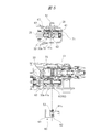
<全体構成> 図1に示されるように、本実施形態に係るハンマドリル1Aは、ハウジング10と,ハウジング10の一端側に設けられたハンドル11と、ハウジング10の他端側に設けられたサブハンドル12と、を有する。
ハウジング10内には、先端工具2の駆動源であるモータ20と、モータ20から出力される駆動力(回転力)を打撃力に変換して先端工具2に伝達する打撃力伝達系30と、モータ20から出力される駆動力(回転力)を先端工具2に伝達する回転力伝達系40と、が設けられている。以下の説明では、打撃力伝達系30および回転力伝達系40を「動力伝達系」と総称する場合がある。
モータ20は、ステータ,ロータおよび出力軸21を有する。出力軸21は、ロータを貫通してハウジング10の長手方向に延びている。本実施形態では、ハウジング10の長手方向、つまり出力軸21の方向を前後方向と定義する。さらに、サブハンドル12が設けられている側を「前方」、ハンドル11が設けられている側を「後方」と定義する。かかる定義に従えば、先端工具2は、駆動源であるモータ20の前方に配置されている。
ロータを貫通して前後方向に延びている出力軸21は、2つの軸受22a,22bによって回動可能に支持されている。軸受22aは出力軸21の前側(先端側)を回転可能に支持し、軸受22bは出力軸21の後ろ側(後端側)を回転可能に支持している。出力軸21の先端側は、軸受22aを貫通して当該軸受22aの前方に突出している。軸受22aの前方に突出している出力軸21の先端には、ギヤ(ピニオン23)が設けられている。
モータ20は、ハンドル11に設けられているトリガ11aの操作に基づいて作動する。具体的には、作業者によってトリガ11aが引かれると、モータ20に電力が供給され、出力軸21が回転する。一方、作業者によるトリガ11aの引きが解除されると、モータ20に対する電力供給が遮断され、出力軸21の回転が停止する。尚、出力軸21には冷却ファン24が装着されている。冷却ファン24は、出力軸21と一体的に回転し、主にモータ20を冷却するための冷却風を発生させる。また、モータ20の周囲には、スイッチング素子を含む駆動回路や、ホール素子を含む制御回路などが配置されており、これら回路も冷却ファン24が発生させる冷却風によって冷却される。
ハウジング10内には、回転軸25およびシリンダ31が出力軸21と平行に配置されている。回転軸25の先端側は軸受25aにより回転可能に支持され、回転軸25の後端側は軸受25bにより回転可能に支持されている。軸受25bを貫通して当該軸受25bの後方に突出している回転軸25の後端には、出力軸21の先端に設けられているピニオン23と係合する従動ギヤ26が設けられている。そして、ドリルモードまたはハンマドリルモードが選択されると、出力軸21の回転が回転軸25を介してシリンダ31に伝達される。つまり、回転軸25は、出力軸21とシリンダ31との間に介在する動力伝達要素の一つである。そこで、以下の説明では、回転軸25を「中間軸25」と呼ぶ場合がある。
<打撃力伝達系> 図1に示されるように、中間軸25上であって軸受25bの前方には、中間軸25の回転運動を往復運動に変換する変換機構32が設けられている。変換機構32は、内輪,外輪,転動体および連結棒から構成されており、「レシプロベアリング」と呼ばれることもある。内輪は中間軸25に対して相対回転可能に支持され、外輪は内輪の周囲に配置され、転動体は内輪と外輪との間に介在している。また、連結棒は、外輪の外周面から当該外輪の径方向外側に向かって延在している。内輪の外周面および外輪の内周面には、断面円弧状の溝がそれぞれ形成されている。転動体は、一部が内輪に形成されている溝に嵌合し、他の一部が外輪に形成されている溝に嵌合した状態で内輪と外輪との間に介在している。言い換えれば、内輪と外輪とは転動体を介して相対回転可能に連結されている。
また、中間軸25上であって変換機構32の前方には、中間軸25に沿って前後に移動可能なクラッチ部材33が設けられている。クラッチ部材33は、中間軸25と常時係合している一方、中間軸25の回転を変換機構32に伝達する係合位置と、中間軸25の回転を変換機構32に伝達しない非係合位置と、に移動可能である。
クラッチ部材33が中間軸25に沿って係合位置まで後退すると、中間軸25と変換機構32とがクラッチ部材33を介して接続され、中間軸25から変換機構32に動力が伝達される。具体的には、中間軸25と一体的に回転するクラッチ部材33の後端に設けられた爪が変換機構32の内輪の前端に設けられた爪と係合し、中間軸25の回転がクラッチ部材33を介して内輪に伝達される。
一方、クラッチ部材33が中間軸25に沿って非係合位置まで前進すると、中間軸25と変換機構32との接続が解除され、中間軸25から変換機構32への動力伝達が遮断される。具体的には、内輪に係合していたクラッチ部材33が内輪から離れ、中間軸25から内輪への動力伝達が遮断される。
上記のようなクラッチ部材33の移動は、作業者による動作モードの切り替え操作に応じて実現される。そして、クラッチ部材33が係合位置にあるときに中間軸25が回転すると、内輪が回転する。すると、内輪の表面に沿って外輪が転動し、これに伴って連結棒が前後に揺動する。
上記のようにして揺動する連結棒は、シリンダ31に収容されているカップ状のピストン34の背面に回動可能に連結されている。シリンダ31には、ピストン34の他に、打撃子35および中間子36が収容されている。これらピストン34,打撃子35,中間子36は、後方から前方に向かってこの順で一列に並んでおり、ピストン34と打撃子35との間には空気室37が設けられている。さらに、シリンダ31の前方には、保持部としてのリテーナスリーブ38が設けられている。リテーナスリーブ38は、シリンダ31の先端側に一体に形成されており、シリンダ31とリテーナスリーブ38とは相対回転不能に連結されている。リテーナスリーブ38には先端工具2の根元部が挿入され、リテーナスリーブ38は、挿入された先端工具2の根元部を所定範囲内で直動可能に保持する。
ピストン34に連結されている連結棒が揺動すると、ピストン34がシリンダ31内で前後に往復動する。ここで、クラッチ部材33が係合位置にあるときに中間軸25が回転すると連結棒が前後に揺動することは既述のとおりである。つまり、変換機構32は、中間軸25の回転運動をピストン34の往復運動に変換する。
シリンダ31内でピストン34が往復動すると、空気室37の圧力が変動する。空気室37の圧力が変動すると、その圧力変動に伴って打撃子35が駆動され、打撃子35によって中間子36が打撃され、中間子36によって先端工具2が打撃される。この結果、リテーナスリーブ38に保持されている先端工具2に打撃力が付与される。
このように、中間軸25は、前後方向に延びる中心軸を中心に、モータ20によって回転駆動される。そして、中間軸25の回転力は、シリンダ31,変換機構32,クラッチ部材33,ピストン34,打撃子35,中間子36,空気室37およびリテーナスリーブ38などから構成される打撃力伝達系30によって打撃力に変換されて先端工具2に伝達される。
<回転力伝達系> 図1に示されるように、中間軸25上であってクラッチ部材33の前方には、中間軸25に沿って前後に移動可能なスリーブ41が設けられている。より詳細には、スリーブ41は、クラッチ部材33と軸受25aとの間に配置されている。既述のとおり、変換機構32は軸受25bの前方に配置され、クラッチ部材33は変換機構32の前方に配置されている。つまり、変換機構32,クラッチ部材33およびスリーブ41は、後方から前方に向かってこの順で並んでおり、かつ、2つの軸受25b,25aの間に配置されている。言い換えれば、中間軸25は、変換機構32,クラッチ部材33およびスリーブ41をこの順で貫通している。
図2(a),(b)に示されるように、スリーブ41の内周面には内側ギヤ42が形成され、スリーブ41の外周面には外側ギヤ43が形成されている。一方、スリーブ41を貫通している中間軸25の外周面には、内側ギヤ42と係合可能な中間ギヤ27が中間軸25と一体で形成されている。
ここで、係合位置および非係合位置のいずれにおいても中間軸25と動力伝達可能に係合するクラッチ部材33は、中間ギヤ27と同じく中間軸25の外周面に形成されているギヤ28と常に係合している。このギヤ28は、中間ギヤ27と同時に中間軸25の外周面に形成されたものである。具体的には、中間軸25の外周面に一連のギヤを形成した後に当該ギヤを前後分断し、一部を中間ギヤ27とし、他の一部をクラッチ部材33と常時係合するギヤ28としたものである。このように、中間軸25上に、スリーブ41と係合する中間ギヤ27およびクラッチ部材33と係合するギヤ28を同時に形成することで、中間軸25の製造コストを低減させることができる。
図2(a)に示されているスリーブ41がクラッチ部材33から離間する方向(前方/紙面右側)に移動すると、図2(b)に示されるように、スリーブ41に形成されている内側ギヤ42が中間軸25に形成されている中間ギヤ27に嵌合し、内側ギヤ42と中間ギヤ27とが係合する。一方、図2(b)に示されているスリーブ41がクラッチ部材33に近接する方向(後方/紙面左側)に移動すると、図2(a)に示されるように、スリーブ41に形成されている内側ギヤ42が中間軸25に形成されている中間ギヤ27から離脱し、内側ギヤ42と中間ギヤ27との係合が解除される。つまり、スリーブ41が前方に移動すると、スリーブ41と中間軸25とが係合する一方、スリーブ41が後方に移動すると、スリーブ41と中間軸25との係合が解除される。
以下の説明では、図2(b)に示されているスリーブ41の位置(スリーブ41と中間軸25とが係合し、先端工具2(図1)に回転力を伝達可能となる位置)を「連結位置」と呼ぶ場合がある。また、図2(a)に示されているスリーブ41の位置(スリーブ41と中間軸25との係合が解除され、先端工具2(図1)に回転力を伝達不能となる位置)を「非連結位置」と呼ぶ場合がある。
図2(a)に示されるように、スリーブ41の内側には、当該スリーブ41が非連結位置に移動したときに、中間ギヤ27が収容される環状溝44が形成されている。言い換えれば、スリーブ41を非連結位置まで後退させ、中間ギヤ27を環状溝44に収容する(逃がす)ことにより、スリーブ41と中間軸25との係合が解除される。スリーブ41と中間軸25との係合が解除されると、中間軸25は、スリーブ41に対して空転する。つまり、環状溝44は、中間ギヤ27と係合することなく、中間ギヤ27を収容する。
再び図1を参照する。シリンダ31の周囲には、スリーブ41に形成されている外側ギヤ43と係合するシリンダギヤ45が形成されている。シリンダギヤ45は、シリンダ31の全周に亘って形成されたリング状のギヤであり、外側ギヤ43とスプライン結合している。よって、スリーブ41が連結位置に移動し、当該スリーブ41と中間軸25とが動力伝達可能に係合すると、中間軸25の回転力が外側ギヤ43およびシリンダギヤ45を介してシリンダ31に伝達され、シリンダ31が回転する。すると、リテーナスリーブ38を介してシリンダ31に連結されている先端工具2に回転力が伝達される。一方、スリーブ41が非連結位置に移動し、スリーブ41と中間軸25との係合が解除されると、シリンダ31への回転力の伝達が遮断され、先端工具2への回転力の伝達も遮断される。
このように、中間軸25は、前後方向に延びる中心軸を中心に、モータ20によって回転駆動される。そして、中間軸25の回転力は、スリーブ41(内側ギヤ42および外側ギヤ43),シリンダ31(シリンダギヤ45)およびリテーナスリーブ38などから構成される回転力伝達系40によって先端工具2に伝達される。
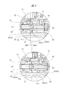
<各動作モードにおけるクラッチ部材およびスリーブの位置> これまでの説明より、クラッチ部材33およびスリーブ41を中間軸25に沿って所定位置に移動させることにより、動作モードが切り替えられることが理解されるはずである。図3に各動作モードにおけるクラッチ部材33およびスリーブ41の位置を示す。図3(a)は、ドリルモード選択時のクラッチ部材33およびスリーブ41の位置を示している。図3(b)は、ハンマドリルモード選択時のクラッチ部材33およびスリーブ41の位置を示している。図3(c)は、ハンマモード選択時のクラッチ部材33およびスリーブ41の位置を示している。
説明の便宜上の理由により、ハンマドリルモード選択時のクラッチ部材33およびスリーブ41の位置(図3(b))について最初に説明する。図3(b)に示されるように、中間軸25の周囲であって、クラッチ部材33とスリーブ41との間には、両者を互いに離間する方向に付勢する弾性体70が設けられている。本実施形態における弾性体70は、中間軸25に巻装されたコイルばねである。コイルばね70は、圧縮状態でクラッチ部材33とスリーブ41との間に配置されている。よって、コイルばね70は、クラッチ部材33を後方に向けて常時付勢し、スリーブ41を前方に向けて常時付勢する。
図3(b)に示されるように、ハンマドリルモード選択時には、コイルばね70の付勢により、クラッチ部材33は係合位置に保持され、スリーブ41は連結位置に保持される。この結果、中間軸25の回転力が打撃力に変換されて先端工具2(図1)に伝達されるとともに、中間軸25の回転力が先端工具2(図1)に伝達される。つまり、図1に示される先端工具2には、打撃力および回転力の双方が付与される。
図3(a)に示されるように、ハンマドリルモードからドリルモードに動作モードが切り替えられると、クラッチ部材33は、コイルばね70の付勢に抗して非係合位置まで前進する一方、スリーブ41の位置は変わらない。つまり、クラッチ部材33は非係合位置に移動する一方、スリーブ41は連結位置に止まる。この結果、図1に示される先端工具2には、打撃力は付与されず、回転力のみが付与される。
図3(c)に示されるように、ハンマドリルモードからハンマモードに動作モードが切り替えられると、スリーブ41は、コイルばね70の付勢に抗して非連結位置まで後退する一方、クラッチ部材33の位置は変わらない。つまり、スリーブ41は非連結位置に移動する一方、クラッチ部材33は係合位置に止まる。この結果、図1に示される先端工具2には、回転力は付与されず、打撃力のみが付与される。
<動作モード切り替えのための操作機構> 次に、上記のようにクラッチ部材33およびスリーブ41を移動させて動作モード切り替えるための機構について具体的に説明する。
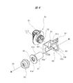
図1に示されるハンマドリル1Aには、クラッチ部材33およびスリーブ41を移動させて動作モードを切り替えるための操作機構が設けられている。操作機構は、図4に示される操作部50やスライダ60などによって構成されている。操作部50は、ハウジング10(図1)の側面に設けられており、作業者によって操作される。スライダ60は、ハウジング10(図1)の内部に設けられており、操作部50の操作に伴って移動し、クラッチ部材33およびスリーブ41を前後に移動させる。具体的には、操作部50は、作業者によって回転操作され、スライダ60は、操作部50の回動に伴って中間軸25上を前後にスライドする。そこで、以下の説明では、操作部50を「ダイヤル50」と呼ぶ場合がある。
図4に示されるダイヤル50は、不図示の支持軸により、ハウジング10(図1)に対して回転可能に支持されている。ダイヤル50の正面には摘み51が形成されており、ダイヤル50の背面には可動部材52が突設されている。可動部材52は、ダイヤル50の回転中心から径方向外側にずれた位置に設けられている。つまり、可動部材52は、ダイヤル50の回転中心に対して偏心しており、ダイヤル50の回動に伴って前後方向に移動する。つまり、本実施形態における可動部材52は、ダイヤル50の背面に突設された偏心ピンである。
スライダ60は、ベースプレート61,前方プレート62および後方プレート63を有する。ベースプレート61は、前後方向を長辺方向とする略長方形に形成されている。前方プレート62および後方プレート63は、ベースプレート61の長手方向両端にそれぞれ連接されており、前後方向において互いに対向している。前方プレート62の先には、ベースプレート61と平行な帯状のガイドプレート64が設けられている。ガイドプレート64は、ハウジング10の内部に設けられているガイド溝に挿入され、スライダ60の前後動を案内する。また、スライダ60は、弾性体71により後方へ付勢されている。本実施形態における弾性体71は、スライダ60とハウジング10との間に挟持されたコイルばねである。
ベースプレート61には、ダイヤル50の背面から突出しているピン52が嵌め込まれる窓61aが形成されている。前方プレート62には、スリーブ41が挿通される略円形の開口部62aが形成されており、後方プレート63には、クラッチ部材33の外形に倣った切欠き63aが形成されている。尚、図4では、スリーブ41に外周面に形成されている外側ギヤ43の図示は省略されている。
図2(b)に示されるように、スライダ60は、クラッチ部材33およびスリーブ41の周囲に、これらに跨って配置される。具体的には、スライダ60は、前方プレート62がスリーブ41に形成されているフランジ41aの前方に位置し、後方プレート63がクラッチ部材33に形成されているフランジ33aの後方に位置するように、クラッチ部材33およびスリーブ41の周囲に配置される。つまり、クラッチ部材33およびスリーブ41のフランジ33a,41aは、スライダ60の後方プレート63と前方プレート62との間に挟まれる。この結果、前方プレート62の背面は、スリーブ41のフランジ41aの前面と対向し、後方プレート63の前面は、クラッチ部材33のフランジ33aの背面と対向する。
再び図4を参照する。既述のとおり、スライダ60は、ダイヤル50の回転操作に伴って中間軸25上を前後に移動する。具体的には、ダイヤル50が回転操作されると、ベースプレート61の窓61aに嵌合されているピン52が変位し、これに伴ってスライダ60が前後に移動する。より具体的には、ダイヤル50を前方に回転させると、ピン52が窓61aの前側の内側面に当接し、スライダ60を前方に向かって押す。一方、ダイヤル50を後方に回転させると、コイルばね71の付勢力により、ピン52の後退に伴って、スライダ60が後方に向かって移動する。
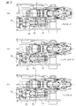
<ダイヤル回転位置とスライダ,クラッチ部材およびスリーブの前後位置> 図5~図7に、ダイヤル50の回転位置と、スライダ60,クラッチ部材33およびスリーブ41の前後位置と、の関係を示す。図5は、ハンマドリルモード選択時における上記各部材の位置関係を示している。図6は、ドリルモード選択時における上記各部材の位置関係を示している。図7は、ハンマモード選択時における上記各部材の位置関係を示している。
図5に示されるように、動作モードをハンマドリルモードに切り替えるときには、摘み51が中間軸25に対して垂直または略垂直になるようにダイヤル50を回転させる。言い換えれば、摘み51が中間軸25に対して垂直または略垂直になるようにダイヤル50を回転させると、他のモードからハンマドリルモードに動作モードが切り替えられる。このとき、ダイヤル50に設けられているピン52は、コイルばね71の付勢力に抗して、スライダ60を前方へ押圧する。よって、スライダ60は、図示されている中立位置に置かれる。スライダ60が中立位置にあるとき、当該スライダ60の前方プレート62は、スリーブ41のフランジ41aに当接せず、スライダ60の後方プレート63は、クラッチ部材33のフランジ33aに当接しない。よって、クラッチ部材33およびスリーブ41は、コイルばね70による付勢のみを受け、クラッチ部材33は係合位置に保持され、スリーブ41は連結位置に保持される。
図6に示されるように、動作モードをドリルモードに切り替えるときには、摘み51が中間軸25に対して平行または略平行になるまでダイヤル50を前方に回転させる。言い換えれば、摘み51が中間軸25に対して平行または略平行になるようにダイヤル50を回転させると、他のモードからドリルモードに動作モードが切り替えられる。このとき、ダイヤル50に設けられているピン52は、窓61aの前側の内側面に当接し、スライダ60を前方に向かって押す。これにより、スライダ60は、図示されている前進位置に移動する。スライダ60が中立位置(図5)から前進位置(図6)に移動すると、クラッチ部材33のフランジ33aの後方に位置している後方プレート63が当該フランジ33aに当接し、クラッチ部材33をコイルばね70の付勢に抗して前方に押し出す。一方、スリーブ41のフランジ41aの前方に位置している前方プレートは、当該フランジ41aから離間する。つまり、クラッチ部材33は前方に移動する一方、スリーブ41は移動しない。この結果、クラッチ部材33は係合位置から非係合位置に移動される一方、スリーブ41は連結位置に保持される。
図7に示されるように、動作モードをハンマモードに切り替えるときには、摘み51が中間軸25に対して平行または略平行になるまでダイヤル50を後方に回転させる。言い換えれば、摘み51が中間軸25に対して平行または略平行になるまでダイヤル50を回転させると、他のモードからドリルモードに動作モードが切り替えられる。このとき、ダイヤル50に設けられているピン52は後退し、これに伴ってスライダ60は、コイルばね71に付勢されて後方へ移動する。これにより、スライダ60は、図示されている後進位置に移動する。スライダ60が中立位置(図5)から後進位置(図7)に移動すると、ピン52がフランジ41aに当接し、スリーブ41をコイルばね70の付勢に抗して後方に押す。一方、クラッチ部材33のフランジ33aの後方に位置している後方プレート63は、当該フランジ33aから離間する。つまり、スリーブ41は後方に移動する一方、クラッチ部材33は移動しない。この結果、スリーブ41は連結位置から非連結位置に移動される一方、クラッチ部材33は係合位置に保持される。
尚、図4に示されるように、前方プレート62の開口部62aの内周には、フランジ41aの前面に形成されている凸部41bが嵌合可能な凹部62bが形成されている。よって、前方プレート62がフランジ41aに当接すると、凸部41bが凹部62bに嵌合し、スリーブ41の不要な回転が規制される。
以上のように、本実施形態に係るハンマドリル1Aが備える回転力伝達系40では、中間軸25からシリンダ31への回転力の伝達が、中間軸25と直接係合するスリーブ41のみを介して行われる。また、中間軸25とスリーブ41との係合を解除すれば、中間軸25からシリンダ31への回転力の伝達が遮断される。つまり、中間軸25とシリンダ31との間に介在する動力伝達要素は、中間軸25に沿って直動するスリーブ41のみであり、回転力伝達系40の部品点数が可及的に削減されている。
本発明は上記実施形態に限定されるものではなく、その要旨を逸脱しない範囲で種々変更可能である。例えば、上記実施形態では、スリーブ41の後方側の端部に内側ギヤ42が形成されていた。しかし、内側ギヤ42は、スリーブ41の前方側の端部に形成することもできる。
図8(a)~(c)に、前側端部に内側ギヤ42が形成されたスリーブ41を有するハンマドリル1Bにおける、クラッチ部材33およびスリーブ41の動作モード毎の位置を示す。図8(a)は、ドリルモード選択時のクラッチ部材33およびスリーブ41の位置を示している。図8(b)は、ハンマドリルモード選択時のクラッチ部材33およびスリーブ41の位置を示している。図8(c)は、ハンマモード選択時のクラッチ部材33およびスリーブ41の位置を示している。
図8(c)に最も明確に示されているように、スリーブ41の前側端部の内周面に内側ギヤ42が形成されている。また、図8(c)に示されている中間ギヤ27は、中間軸25と一体で形成されている点は図3(c)と同様だが、図3(c)に示されている中間ギヤ27に比べて、中間軸25の先端寄りに設けられている。さらに、図8(c)に示されているスリーブ41には、図2(a),(b)に示されるスリーブ41に設けられている環状溝44が設けられていない。
もっとも、ハンマモード(図8(c))からドリルモード(図8(a))またはハンマドリルモード(図8(b))に動作モードが切り替えられると、スリーブ41が前方に移動し、スリーブ41と中間軸25とが係合する点は、上記実施形態と同様である。また、ドリルモード(図8(a))またはハンマドリルモード(図8(b))からハンマモード(図8(c))に動作モードが切り替えられると、スリーブ41が後方に移動し、スリーブ41と中間軸25との係合が解除される点も、上記実施形態と同様である。
言い換えれば、ハンマドリルモードおよびドリルモード選択時には、ハンマモード選択時に比べて、スリーブ41が前方に位置する点は、上記実施形態と同様である。また、ハンマモード選択時には、ドリルモードおよびハンマドリルモード選択時に比べて、スリーブ41が後方に位置する点も、上記実施形態と同様である。
本発明に係る打撃作業機は、上記3つの動作モード(ドリルモード,ハンマモード,ハンマドリルモード)を備える打撃作業機に限定されない。例えば、本発明に係る打撃作業機には、ハンマモードおよびハンマドリルモードの2つの動作モードのみを備える打撃作業機も含まれる。ハンマモードおよびハンマドリルモードの2つの動作モードのみを備える打撃作業機では、上記実施形態におけるクラッチ部材33が省略される。
本発明に係る打撃作業機は、ハンマドリルに限定されない。本発明は、ハンマドリル以外の打撃作業機に適用された場合にも上記と同一または実質的に同一の作用効果を奏する。
1A,1B…ハンマドリル、2…先端工具、10…ハウジング、11…ハンドル、11a…トリガ、12…サブハンドル、20…モータ、21…出力軸、22a,22b,25a,25b…軸受、23…ピニオン、24…冷却ファン、25…回転軸(中間軸)、26…従動ギヤ、27…中間ギヤ、30…打撃力伝達系、31…シリンダ、32…変換機構、33…クラッチ部材、33a,41a…フランジ、34…ピストン、35…打撃子、36…中間子、37…空気室、38…リテーナスリーブ、40…回転力伝達系、41…スリーブ、41b…凸部、42…内側ギヤ、43…外側ギヤ、44…環状溝、45…シリンダギヤ、50…操作部(ダイヤル)、52…可動部材(ピン)、60…スライダ、61…ベースプレート、61a…窓、62…前方プレート、62a…開口部、62b…凹部、63…後方プレート、64…ガイドプレート、70,71…弾性体(コイルばね)
Claims (11)
- 駆動源と、
前記駆動源の前方に配置され、打撃力と回転力の一方または双方が付与される先端工具と、
前後方向に延びる中心軸を中心に、前記駆動源によって回転駆動される回転軸と、
前記回転軸の回転力を前記先端工具に伝達する回転力伝達系と、を備える打撃作業機であって、
前記回転力伝達系は、前記回転軸上に、前後方向に移動可能に設けられるスリーブを含み、
前記スリーブが前方に移動すると、当該スリーブと前記回転軸とが係合して、前記先端工具に回転力を伝達可能となり、
前記スリーブが後方に移動すると、当該スリーブと前記回転軸との係合が解除されて、前記先端工具に回転力を伝達不能となる、打撃作業機。 - 前記スリーブの内周面に内側ギヤが形成され、
前記スリーブの外周面に外側ギヤが形成され、
前記スリーブが前方に移動すると、前記内側ギヤが前記回転軸の外周面に形成されている中間ギヤと係合し、
前記スリーブが後方に移動すると、前記内側ギヤと前記中間ギヤとの係合が解除される、請求項1に記載の打撃作業機。 - 前記内側ギヤは、前記スリーブの後方側の端部に形成されている、請求項2に記載の打撃作業機。
- 前記内側ギヤは、前記スリーブの前方側の端部に形成されている、請求項2に記載の打撃作業機。
- 前記スリーブの内側に、当該スリーブが後方に移動したときに、前記中間ギヤと係合することなく当該中間ギヤを収容する環状溝が形成されている、請求項2~4のいずれか一項に記載の打撃作業機。
- 前記回転軸の回転力を打撃力に変換して前記先端工具に伝達する打撃力伝達系を備え、
前記打撃力伝達系は、
前記回転軸の回転運動を往復運動に変換する変換機構と、
前記回転軸上に、前後方向に移動可能に設けられ、前記回転軸から前記変換機構に動力が伝達される係合位置と、前記回転軸から前記変換機構に動力が伝達されない非係合位置と、に移動するクラッチ部材と、を含み、前記クラッチ部材は、前記係合位置および前記非係合位置のいずれにおいても、前記回転軸と動力伝達可能に係合する、請求項1~5のいずれか一項に記載の打撃作業機。 - 前記回転軸を回転可能に支持する2つの軸受を有し、
前記変換機構,クラッチ部材およびスリーブは、この順で前記2つの軸受の間に配置されている、請求項6に記載の打撃作業機。 - 前記打撃力伝達系は、シリンダおよび当該シリンダに収容されたピストンをさらに含み、
前記変換機構は、前記回転軸の回転運動を前記ピストンの往復運動に変換し、
前記回転力伝達系は、前記シリンダの周囲に設けられ、前記スリーブに形成されている前記外側ギヤと係合するシリンダギヤをさらに含む、請求項6または7に記載の打撃作業機。 - 作業者によって操作される操作部と、
前記操作部の操作に伴って移動し、前記スリーブを前後方向に移動させる可動部材と、を有する、請求項6~8のいずれか一項に記載の打撃作業機。 - 前記回転軸の周囲に設けられ、前記クラッチ部材と前記スリーブとを互いに離間する方向に付勢する弾性体を有し、
前記可動部材は、前記スリーブを前記弾性体の付勢に抗して後方に移動させる、請求項9に記載の打撃作業機。 - 前記駆動源としてのモータを有し、
前記回転軸の一端には、前記モータの出力軸の一端に設けられているピニオンと係合する従動ギヤが設けられ、
前記出力軸,回転軸およびシリンダは、互いに平行に配置されている、請求項8~10のいずれか一項に記載の打撃作業機。
Priority Applications (3)
| Application Number | Priority Date | Filing Date | Title |
|---|---|---|---|
| CN201980078438.2A CN113165152B (zh) | 2018-11-29 | 2019-10-25 | 打击作业机 |
| JP2020558192A JP7331864B2 (ja) | 2018-11-29 | 2019-10-25 | 打撃作業機 |
| DE112019005160.1T DE112019005160T5 (de) | 2018-11-29 | 2019-10-25 | Schlagarbeitsgerät |
Applications Claiming Priority (2)
| Application Number | Priority Date | Filing Date | Title |
|---|---|---|---|
| JP2018-222997 | 2018-11-29 | ||
| JP2018222997 | 2018-11-29 |
Publications (1)
| Publication Number | Publication Date |
|---|---|
| WO2020110539A1 true WO2020110539A1 (ja) | 2020-06-04 |
Family
ID=70853237
Family Applications (1)
| Application Number | Title | Priority Date | Filing Date |
|---|---|---|---|
| PCT/JP2019/041959 Ceased WO2020110539A1 (ja) | 2018-11-29 | 2019-10-25 | 打撃作業機 |
Country Status (4)
| Country | Link |
|---|---|
| JP (1) | JP7331864B2 (ja) |
| CN (1) | CN113165152B (ja) |
| DE (1) | DE112019005160T5 (ja) |
| WO (1) | WO2020110539A1 (ja) |
Citations (5)
| Publication number | Priority date | Publication date | Assignee | Title |
|---|---|---|---|---|
| JPS5015653B1 (ja) * | 1970-12-02 | 1975-06-06 | ||
| JPS582760B2 (ja) * | 1975-08-19 | 1983-01-18 | マシ−ネンフアブリ−ク・ケツペルン・ゲゼルシヤフト・ミツト・ベシユレンクテル・ハフツング・ウント・コンパニイ・コマンデイ−ト・ゲゼルシヤフト | 粒状物の熱間圧縮練製のためのロ−ルプレス |
| JPH07328955A (ja) * | 1994-06-09 | 1995-12-19 | Hitachi Koki Co Ltd | ハンマドリル |
| JP2003245872A (ja) * | 2002-02-22 | 2003-09-02 | Makita Corp | ハンマードリル |
| WO2017073236A1 (ja) * | 2015-10-30 | 2017-05-04 | 日立工機株式会社 | ハンマドリル |
Family Cites Families (8)
| Publication number | Priority date | Publication date | Assignee | Title |
|---|---|---|---|---|
| JP3582760B2 (ja) * | 1997-04-18 | 2004-10-27 | 日立工機株式会社 | ハンマドリル |
| JP4446248B2 (ja) * | 2004-11-24 | 2010-04-07 | 日立工機株式会社 | ハンマドリル |
| JP5055749B2 (ja) * | 2005-11-16 | 2012-10-24 | マックス株式会社 | ハンマドリル |
| CN100513090C (zh) * | 2007-10-30 | 2009-07-15 | 常州赛迪电气制造有限公司 | 双速多功能电锤 |
| JP5431000B2 (ja) * | 2009-04-01 | 2014-03-05 | 株式会社マキタ | ハンマードリル |
| EP2979819A4 (en) * | 2013-03-26 | 2016-11-16 | Hitachi Koki Kk | POWER TOOL |
| WO2015045734A1 (ja) * | 2013-09-27 | 2015-04-02 | 日立工機株式会社 | 打撃工具 |
| JP6709120B2 (ja) * | 2016-07-15 | 2020-06-10 | 株式会社マキタ | 打撃工具 |
-
2019
- 2019-10-25 DE DE112019005160.1T patent/DE112019005160T5/de active Pending
- 2019-10-25 JP JP2020558192A patent/JP7331864B2/ja active Active
- 2019-10-25 WO PCT/JP2019/041959 patent/WO2020110539A1/ja not_active Ceased
- 2019-10-25 CN CN201980078438.2A patent/CN113165152B/zh active Active
Patent Citations (5)
| Publication number | Priority date | Publication date | Assignee | Title |
|---|---|---|---|---|
| JPS5015653B1 (ja) * | 1970-12-02 | 1975-06-06 | ||
| JPS582760B2 (ja) * | 1975-08-19 | 1983-01-18 | マシ−ネンフアブリ−ク・ケツペルン・ゲゼルシヤフト・ミツト・ベシユレンクテル・ハフツング・ウント・コンパニイ・コマンデイ−ト・ゲゼルシヤフト | 粒状物の熱間圧縮練製のためのロ−ルプレス |
| JPH07328955A (ja) * | 1994-06-09 | 1995-12-19 | Hitachi Koki Co Ltd | ハンマドリル |
| JP2003245872A (ja) * | 2002-02-22 | 2003-09-02 | Makita Corp | ハンマードリル |
| WO2017073236A1 (ja) * | 2015-10-30 | 2017-05-04 | 日立工機株式会社 | ハンマドリル |
Also Published As
| Publication number | Publication date |
|---|---|
| CN113165152B (zh) | 2024-08-30 |
| DE112019005160T5 (de) | 2021-08-19 |
| JP7331864B2 (ja) | 2023-08-23 |
| JPWO2020110539A1 (ja) | 2021-09-30 |
| CN113165152A (zh) | 2021-07-23 |
Similar Documents
| Publication | Publication Date | Title |
|---|---|---|
| US5588496A (en) | Slip clutch arrangement for power tool | |
| JP4828926B2 (ja) | ハンマードリル | |
| JP5468570B2 (ja) | 打撃工具 | |
| US7748472B2 (en) | Hammer drill | |
| US7549484B2 (en) | Power tool | |
| US20190061132A1 (en) | Power tool | |
| US11318596B2 (en) | Power tool having hammer mechanism | |
| AU2004202111A1 (en) | Rotary hammer | |
| JP5340881B2 (ja) | 打撃工具 | |
| JP2004082557A (ja) | ハンマードリル | |
| US7296635B2 (en) | Rotary hammer with mode change ring | |
| JP4446248B2 (ja) | ハンマドリル | |
| JP5055749B2 (ja) | ハンマドリル | |
| US20230118960A1 (en) | Power tool | |
| JP5007955B2 (ja) | ハンマドリル | |
| JP2828657B2 (ja) | ハンマードリル | |
| JP5668525B2 (ja) | 電動工具 | |
| WO2020110539A1 (ja) | 打撃作業機 | |
| JPH06262413A (ja) | 回転工具における動力切換機構 | |
| US10399216B2 (en) | Rotary hammer | |
| JP4405378B2 (ja) | 電動工具 | |
| US12246426B2 (en) | Rotary hammer | |
| JP4556180B2 (ja) | ハンマドリル | |
| JP2012171063A (ja) | 打撃工具 | |
| JP2024168766A (ja) | 打撃工具 |
Legal Events
| Date | Code | Title | Description |
|---|---|---|---|
| 121 | Ep: the epo has been informed by wipo that ep was designated in this application |
Ref document number: 19890785 Country of ref document: EP Kind code of ref document: A1 |
|
| ENP | Entry into the national phase |
Ref document number: 2020558192 Country of ref document: JP Kind code of ref document: A |
|
| 122 | Ep: pct application non-entry in european phase |
Ref document number: 19890785 Country of ref document: EP Kind code of ref document: A1 |