WO2020110485A1 - トルクチューニング方法及びトルクチューニングシステム - Google Patents
トルクチューニング方法及びトルクチューニングシステム Download PDFInfo
- Publication number
- WO2020110485A1 WO2020110485A1 PCT/JP2019/040399 JP2019040399W WO2020110485A1 WO 2020110485 A1 WO2020110485 A1 WO 2020110485A1 JP 2019040399 W JP2019040399 W JP 2019040399W WO 2020110485 A1 WO2020110485 A1 WO 2020110485A1
- Authority
- WO
- WIPO (PCT)
- Prior art keywords
- torque
- motor
- ball stud
- housing
- ball
- Prior art date
- Legal status (The legal status is an assumption and is not a legal conclusion. Google has not performed a legal analysis and makes no representation as to the accuracy of the status listed.)
- Ceased
Links
Images



Classifications
-
- B—PERFORMING OPERATIONS; TRANSPORTING
- B60—VEHICLES IN GENERAL
- B60G—VEHICLE SUSPENSION ARRANGEMENTS
- B60G21/00—Interconnection systems for two or more resiliently-suspended wheels, e.g. for stabilising a vehicle body with respect to acceleration, deceleration or centrifugal forces
- B60G21/02—Interconnection systems for two or more resiliently-suspended wheels, e.g. for stabilising a vehicle body with respect to acceleration, deceleration or centrifugal forces permanently interconnected
- B60G21/04—Interconnection systems for two or more resiliently-suspended wheels, e.g. for stabilising a vehicle body with respect to acceleration, deceleration or centrifugal forces permanently interconnected mechanically
- B60G21/05—Interconnection systems for two or more resiliently-suspended wheels, e.g. for stabilising a vehicle body with respect to acceleration, deceleration or centrifugal forces permanently interconnected mechanically between wheels on the same axle but on different sides of the vehicle, i.e. the left and right wheel suspensions being interconnected
- B60G21/055—Stabiliser bars
-
- F—MECHANICAL ENGINEERING; LIGHTING; HEATING; WEAPONS; BLASTING
- F16—ENGINEERING ELEMENTS AND UNITS; GENERAL MEASURES FOR PRODUCING AND MAINTAINING EFFECTIVE FUNCTIONING OF MACHINES OR INSTALLATIONS; THERMAL INSULATION IN GENERAL
- F16C—SHAFTS; FLEXIBLE SHAFTS; ELEMENTS OR CRANKSHAFT MECHANISMS; ROTARY BODIES OTHER THAN GEARING ELEMENTS; BEARINGS
- F16C11/00—Pivots; Pivotal connections
- F16C11/04—Pivotal connections
- F16C11/06—Ball-joints; Other joints having more than one degree of angular freedom, i.e. universal joints
-
- F—MECHANICAL ENGINEERING; LIGHTING; HEATING; WEAPONS; BLASTING
- F16—ENGINEERING ELEMENTS AND UNITS; GENERAL MEASURES FOR PRODUCING AND MAINTAINING EFFECTIVE FUNCTIONING OF MACHINES OR INSTALLATIONS; THERMAL INSULATION IN GENERAL
- F16C—SHAFTS; FLEXIBLE SHAFTS; ELEMENTS OR CRANKSHAFT MECHANISMS; ROTARY BODIES OTHER THAN GEARING ELEMENTS; BEARINGS
- F16C43/00—Assembling bearings
- F16C43/02—Assembling sliding-contact bearings
Definitions
- the present invention relates to a ball joint, which plays a role of reducing a shock from a road surface of a vehicle, by adjusting a frictional force between a ball portion of a ball stud to be inserted into a housing and a spherical surface inside the housing so that a rocking torque and a rotating torque are adjusted.
- the present invention relates to a torque tuning method and a torque tuning system for adjusting the above.
- the vehicle suspension reduces the impact transmitted from the road surface to the car body, and the stabilizer enhances the roll rigidity (rigidity against torsion) of the car body.
- the suspension and the stabilizer are connected via a stabilizer link.
- the stabilizer link is configured by providing ball joints at both ends of a rod-shaped support bar.
- a ball joint there is a configuration in which the ball portion of the ball stud is rotatably housed in a resin-shaped cup-shaped housing.
- the inside of the housing having this configuration has a spherical curved surface along the spherical shape of the ball portion.
- This spherical curved surface is also referred to as a spherical surface inside the housing.
- a joint device described in Patent Document 1 This joint device is configured by fitting a joint ball (ball portion) of a ball stud into a housing notch (a spherical surface inside the housing).
- the swing torque, the rotation torque, and the elastic lift amount change according to the frictional force when the ball portion rotates.
- the ball portion and the inner spherical surface of the housing oscillate as the suspension of the vehicle makes a stroke.
- the characteristics of the oscillating slide are defined as the oscillating torque and the rotating torque. If the frictional force at the time of rotation of the ball portion increases and the rocking torque and the rotation torque increase, the riding comfort deteriorates.
- the above-mentioned elastic lift amount is the movement amount of the ball portion with respect to the spherical surface inside the housing.
- the frictional force decreases, the amount of elastic lift increases, and the ball portion moves largely on the spherical surface inside the housing.
- backlash is generated in the ball joint, which causes abnormal noise while the vehicle is traveling. That is, when the frictional force decreases, the swing torque and the rotation torque decrease, but the elastic lift amount increases, which is a reciprocal relationship.
- the present invention has been made in view of such a background, and a torque tuning method and a torque tuning method capable of appropriately adjusting a frictional force between a ball portion of a ball stud enclosed by a housing inner spherical surface and the housing inner spherical surface.
- An object is to provide a torque tuning system.
- the torque tuning method of the present invention is a ball stud in which a metallic spherical body is integrally joined to the other end of a stud whose one end is connected to a structure,
- a ball joint having an inner spherical surface including a spherical portion of a ball stud and a resin housing having an open space on one side, torque tuning for adjusting a frictional force between the inner spherical surface of the housing and the spherical portion.
- the ball stud of the test body is rotated by a motor around the axis of the ball stud, and at the time of this rotation, the rotational torque of the motor increases and decreases from the apex, and the curve that rises again from the lowered bottom
- the step of defining the rotation torque of the bottom when drawing as a reference value the step of including the spherical portion of the torque tuning target in the housing by insert molding, and the ball stud of the torque tuning target centering on the axis, Rotating the motor at a speed equal to or higher than the speed at which the inner spherical surface that covers the spherical portion is worn; measuring the rotation torque of the motor during the rotation; and when the measured rotation torque becomes the reference value, And a step of stopping the motor.
- the torque tuning method of the present invention includes a ball stud in which a metallic spherical portion is integrally joined to the other end of a stud portion whose one end is connected to the structure, and a spherical portion of the ball stud.
- the step of measuring the torque and the differential value of the curve connecting the measured rotational torque with a line according to the elapsed time are calculated, and the differential value becomes 0, and then the differential value approximates to 0. And a step of stopping the motor.
- the torque tuning method of the present invention includes a ball stud in which a metallic spherical portion is integrally joined to the other end of a stud portion whose one end is connected to the structure, and a spherical portion of the ball stud.
- a ball joint comprising a resin housing having an inner spherical surface and one of which has an open space, which is a torque tuning method for adjusting a frictional force between the inner spherical surface of the housing and the spherical body portion.
- the ball stud is rotated by the first motor about the axis of the ball stud, and the housing or the ball stud is rocked by using the rotary drive of the second motor to respond to the rotary drive of the second motor.
- the rocking torque rises and falls from the apex, and the step of defining the rocking torque of the bottom when drawing a curve rising again from the lowered bottom is used as a reference value, and the spherical portion of the torque tuning target is insert-molded into the housing.
- the torque tuning system of the present invention includes a ball stud in which a metallic ball portion is integrally joined to the other end of a stud portion whose one end is connected to the structure, and a ball portion of the ball stud.
- a resin housing having an inner spherical surface and a space having one opening, and a torque tuning system for adjusting a frictional force between the inner spherical surface of the housing and the spherical body portion, wherein the ball stud is the ball stud.
- a motor that rotates about the axis of the shaft, a measuring instrument that measures the rotation torque of the motor during the rotation, and a rotation torque of the motor that increases when the ball stud rotates and that decreases from the apex.
- the rotation torque of the bottom when drawing a rising curve is set as a reference value, and a power supply control device that supplies power to the motor and the measuring instrument is provided, and the power supply control device is configured such that the measured rotation torque is the The motor is stopped when the reference value is reached.
- FIG. 9 is a diagram showing curves C1 to C3 of the rotation torque of the motor according to the processing time when the ball stud rotates.
- FIG. 1 is a vertical sectional view of a ball joint of a stabilizer link according to an embodiment of the present invention.
- the ball joint J shown in FIG. 1 is insert-molded by a resin outer housing (housing) 11 so as to cover the ball portion (sphere portion) 10b at the tip end portion of the ball stud 10, and the ball portion 10b and the ball portion 10b. It is insert-molded so that the tip portion 1a1 of the support bar 1a for joint connection is integrally connected.
- the inner spherical surface (also referred to as the inner spherical surface of the housing) 11a of the housing 11 including the spherical ball portion 10b made of metal has a spherical curved shape along the spherical shape of the ball portion 10b.
- the stabilizer link 1 is configured to include the above-mentioned ball joints J at both ends of a rod-shaped support bar.
- one end portion of the suspension indicated by reference numeral 2 or one end portion of the stabilizer is inserted through the through hole to the position of the collar portion 10a1 and is fixed by being tightened with the nut N1.
- the suspension 2 or the stabilizer 2 configures the structure described in the claims.
- the ball stud 10 has a structure in which a spherical ball portion 10b is integrally connected to one end of a rod-shaped stud portion 10s.
- a male screw 10n is threaded on the stud portion 10s.
- a flange portion 10a1 and a small flange portion 10a2, which extend in a circular shape, are formed separately from each other on the tip side (ball portion 10b side) of the male screw 10n.
- a dust cover 13 is arranged between the upper end of the outer housing 11 and the flange 10a1.
- the ball portion 10b at one end of the ball stud 10 is covered with the spherical inner spherical surface 11a of the housing, and the covered metal ball portion 10b and the metal support bar 1a are made of resin. It is integrally contained and fixed by a made outer housing 11.
- a steel pipe is used as a metal material, and the tip end portion 1a1 is pressed in the direction in which the ball stud 10 extends to be deformed into a flat plate shape.
- the support bar 1a may be made of resin or other material besides metal. Further, when the support bar 1a is made of resin, it may be integrated with the outer housing 11.
- a cylindrical straight portion 10s1 is formed on the lower side (ball portion 10b side) of the small flange portion 10a2 that is formed around the stud portion 10s.
- a straight column-shaped straight portion 10s2 having a predetermined length (for example, 1 mm) below the R portion 10a3 below the small brim portion 10a2 is provided, and from below the straight portion 10s2 to a position near the ball portion 10b, A taper shape (conical shape) that becomes thinner as the ball portion 10b gets closer may be used.
- the outer housing 11 is made of PA66-GF30 (PA66 with 30% glass fiber by weight).
- the material of the housing 11 may be any as long as the strength requirement is satisfied.
- engineering plastics such as PEEK (polyetheretherketone), PA66 (Polyamide66), PPS (PolyPhenyleneSulfideResin), POM (polyoxymethylene), super engineering plastics, FRP (Fiber Reinforced Plastics), GRP (glass reinforced plastic) : Glass fiber reinforced plastic), CFRP (Carbon Fiber Reinforced Plastics), etc. are used.
- the inner spherical surface 11a of the housing is required to have a predetermined wear durability because the ball portion 10b of the ball stud 10 sways and slides. Further, since the housing 11 is formed by insert molding, thermoplastic resin is preferable.
- the housing 11 is formed with an annular convex flange 11f having a tapered (conical) tapered portion 11f1 that extends outward from the upper end 11u of the inner spherical surface 11a.
- the starting point of the tapered portion 11f1 is the outer corner 11u1 of the upper end 11u.
- the inclination angle of the tapered portion 11f1 which is the inner peripheral surface of the convex flange 11f, is designed so as to satisfy the swing angle of the ball stud 10 when the ball stud 10 swings, as indicated by the double-headed arrow ⁇ 1. ing.
- the embedded portion of the iron link 13a of the dust cover 13 is press-fitted and fixed to the outer peripheral surface of the convex flange 11f.
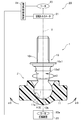
- FIG. 2 is a diagram showing a configuration of a torque tuning system for the ball joint J.
- the ball joint J shown in FIG. 2 is a partial cross-sectional view when the ball joint J shown in FIG. 1 is viewed from the arrow Y1 direction.
- An axis V passing through the center of the ball portion 10b perpendicularly to the horizontal line H is the axis of the ball stud 10.
- the diameter of the ball portion 10b on the horizontal line H is also called the equator S.
- Torque tuning is a process of appropriately adjusting the swinging torque and the rotating torque of the ball stud 10 and the elastic lift amount by adjusting the frictional force between the ball portion 10b of the ball joint J and the inner spherical surface 11a of the housing. .. As shown in FIG. 2, the torque tuning is performed by rotating the ball stud 10 as shown by an arrow ⁇ 2 and swinging the housing 11 left and right as shown by a two-way arrow ⁇ 3 so that the housing inner spherical surface 11a is rotated. While the ball portion 10b is rotated, the inner spherical surface 11a of the housing is swung. This torque tuning method will be described.
- the rotation direction of the stud 10 may be opposite to the arrow ⁇ 2, and the swinging direction ⁇ 3 may be any direction. Further, the swing torque and the rotation torque are abbreviated as torque, and the elastic lift amount is abbreviated as a lift amount.
- a torque tuning system (also referred to as a system) 20 shown in FIG. 2 includes a ball stud 10, a rotary torque meter (also referred to as a meter) 21, a motor 22, an oscillating device 23 having a motor 23 a, and a power supply control device 24. Is configured.
- the meter 21 constitutes the measuring device described in the claims.
- the rotation axis of the motor 22 is fixed to the ball stud 10 via the meter 21 so that the rotation axis of the motor 22 and the axis V of the ball stud 10 are aligned with each other.
- fluctuation apparatus 23 is equipped with the rocking
- the oscillating mechanism oscillates the housing 11 left and right (see FIG. 4) as shown by an arrow ⁇ 3 with the horizontal line H passing through the center of the ball portion 10b as a central axis.
- a power supply control device 24 that supplies power is connected to the meter 21, the motor 22, and the rocking device 23.
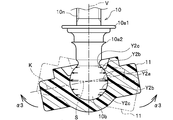
- FIG. 3 shows a partial cross-sectional structure of the front surface of the ball joint J shown in FIG. 1 when viewed from the direction of the arrow Y1.
- the central axis K in the lateral width direction passing through the center of the ball portion 10b in the housing 11 in the horizontal state is in a state of being aligned with the equator S of the ball portion 10b.
- the temperature in the vicinity of the equator S of the ball portion 10b becomes the highest and the inner spherical surface 11a of the housing is largely deformed. Become. However, the temperature of the ball portion 10b due to frictional heat is lower than the melting point of the resin housing 11 and is controlled so that the housing 11 is deformable.
- the contact position of the equator S of the ball portion 10b on the inner spherical surface 11a of the housing changes as the housing 11 swings left and right.
- the contact position of the equator S on the inner spherical surface 11a may be changed by rocking the ball stud 10 and the ball portion 10b with the housing 11 fixed. In this case, the rocking device is assembled to the ball stud 10.
- the ball stud 10 is returned to a state where the ball stud 10 is vertical with respect to the horizontal housing 11 and fixed only after the rocking is started at the time of rotation, and the ball portion 10b is rotated, the inner spherical surface 11a is deformed at the equator S. It is also possible to make it the largest and to make it smaller as it goes up and down from the equator S.
- FIG. 5 shows an example of measuring the measured rotational torque (N ⁇ m).
- the curve C1 shown in FIG. 5 shows the rotational torque that changes with the passage of time from time t0 to time t8.
- the measured rotation torque gradually increases after the rotation of the ball portion 10b and the swing of the housing 11 is started, and rises in a steep curve near time t2a, and at the time t3a, the peak of the torque T8a (N ⁇ m). Reach the top. Furthermore, the rotational torque descends from the top in a gentle curve, reaches the bottom (bottom) of the torque T1a (N ⁇ m) at time t6a, and rises from this bottom to the torque T2a (N ⁇ m) at time t7a.
- the pulse shape changes to C3.
- the rotating torque near the apex of the pulse-like C3 is a torque for generating a burr that melts a part of the upper part of the inner spherical surface 11a of the housing and jumps out. Therefore, after the rotation and the swing of the ball portion 10b are started, if the rotation and the swing are stopped at the level where the rotation torque becomes the top and then the bottom, the friction between the ball portion 10b and the housing inner spherical surface 11a. You can adjust the force to a small level. In other words, it is possible to adjust the swinging torque and the rotating torque of the ball stud 10 and the frictional force so that the elastic lift amount can be adjusted appropriately (small).
- the curves C1 and C3 of the rotational torque characteristic are obtained in advance by an experiment, and the torque at the level where the rotational torque becomes the top and then the bottom from the curves C1 and C3 is set as the reference value T1a.
- This reference value T1a is stored (held) and set in a storage unit (not shown) of the power supply control device 24 shown in FIG.
- the power supply control device 24 supplies power to the rocking device 23, the motor 22, and the meter 21, and after starting the rocking device 23 and the motor 22, when the rotational torque measured by the meter 21 reaches the reference value T1a.
- the control for stopping the operations of the rocking device 23 and the motor 22 and the power supply is performed.
- the inner spherical surface 11a of the housing is expanded and deformed into a shape in which the rotation torque of the motor 22 is reduced. Even if the ball portion 10b is cooled in this deformed state, the expanded deformation of the inner spherical surface 11a is maintained. Therefore, the swinging torque and the rotating torque of the ball stud 10 and the elastic lift amount can be properly adjusted.
- the ball portion 10b may be rotated only by the motor 22, and the rotation operation of the motor 22 may be stopped when the rotation torque measured by the meter 21 reaches the reference value T1a.
- the torque tuning method includes a ball stud 10 in which a metal ball portion 10b is integrally joined to the other end of a stud portion, one end of which is connected to the suspension 2 or the stabilizer 2 as a structure, and the ball stud 10.
- a ball joint having an inner spherical surface 11a including the ball portion 10b and a housing 11 made of resin having an open space on one side, the frictional force between the inner spherical surface 11a of the housing 11 and the ball portion 10b is adjusted. It is a thing.
- the torque tuning method is characterized in that the ball stud 10 of the test body is rotated by the motor 22 around the axis of the ball stud 10, and the rotation torque of the motor 22 increases and decreases from the top during this rotation.
- the rotation torque of the bottom when drawing a curve that rises again from the lowered bottom is set as the reference value.
- the ball portion 10b to be torque-tuned is included in the housing 11 by insert molding.
- the ball stud 10 to be torque-tuned is rotated by the motor 22 about the shaft center of the ball stud 10 at a speed not less than the speed at which the inner spherical surface 11a covering the ball portion 10b is worn.
- the rotation torque of the motor 22 is measured during rotation.
- the motor 22 is stopped when the measured rotation torque reaches the reference value.
- the inner spherical surface 11a of the housing 11 is deformed by the friction with the ball portion 10b, so that the rotation torque of the motor 22 is changed.
- the motor 22 stops. Since the reference value is the bottom value after the rotational torque of the motor 22 after rotation reaches its peak, the motor 22 will stop when the rotational torque reaches a predetermined low value.
- the inner spherical surface 11a of the housing 11 expanded and deformed so that the rotational torque has a predetermined small value is retained even when the ball portion 10b is cooled. Therefore, the swinging torque and the rotating torque of the ball stud 10 and the elastic lift amount can be properly adjusted. Further, by setting the reference value to a desired value, it becomes possible to control the rotational torque to a desired value.
- the torque tuning method further includes rocking the housing 11 (or the ball stud 10) with the rocking device 23 when the ball stud 10 is rotated by the motor 22, and rocking when the motor 22 is stopped. To stop.
- the system 20 includes a motor 22 that rotates the ball stud 10 around the axis of the ball stud 10, a meter 21 that measures the rotational torque of the motor 22 when the ball stud 10 rotates, and a motor 22 that rotates the ball stud 10 when the ball stud 10 rotates.
- the rotation torque of the bottom rises when the rotation torque rises and falls from the apex, and when the curve rises again from the bottom, the bottom rotation torque is set as a reference value, and a power supply controller 24 that supplies power to the motor 22 and the meter 21 is provided. Then, the power supply control device 24 controls to stop the motor 22 when the rotational torque measured by the meter 21 reaches the reference value.
- the system 20 further includes a swing device 23 that swings the housing 11 (or the ball stud 10) when the ball stud 10 is rotated by the motor 22 and stops the swing when the motor 22 is stopped.
- the first modification of the present embodiment is that the power supply control device 24 does not hold the reference value T1a and performs the following control. That is, when the ball stud 10 is rotated by the motor 22 and the rocking device 23 and the housing 11 (or the ball stud 10) is rocked, the power supply control device 24 shows the rotational torque measured by the meter 21 as shown in FIG. Thus, the curve C1 is drawn by plotting according to the elapsed time, and the differential value of the curve C1 is calculated at this time. The calculation of the differential value may be performed by linearly correcting the curve C1. The power supply control device 24 performs control to stop the rotation and swing when the differential value becomes 0 and then becomes the differential value close to 0.
- the power supply control device 24 performs control to stop the rotation and swing when the differential value changes from negative to positive. You can
- the torque tuning method of the second modification of the present embodiment is that the rotation and swing of the ball stud 10 are stopped when the swing torque of the housing 11 when swinging reaches a reference value.
- the system configuration in this case uses an oscillating torque meter (not shown) that measures the rotational driving torque of the motor 23a in the oscillating device 23 shown in FIG. 2 as an oscillating torque.
- the measured swing torque draws a curve having the same tendency as the curves C1 and C3 of the rotation torque shown in FIG.
- the motor 22 that rotates the ball stud 10 constitutes a first motor recited in the claims, and the motor 23a constitutes a second motor recited in the claims.
- the rocking torque meter constitutes the measuring device described in the claims.
- the torque at the level where the swing torque becomes the top and then the bottom is stored as a reference value of the swing torque in a storage unit (not shown) of the power supply control device 24. And set it.
- the power control device 24 supplies power to the rocking device 23, the motor 22, and the meter 21, and after the rocking device 23 and the motor 22 are started, the rocking torque measured by the torque meter becomes a reference value. Then, control is performed to stop the operation of the rocking device 23 and the motor 22 and the power supply.
- the ball stud 10 may be swung by a swing device (not shown) having the motor 23a.
- the motor 22 rotates the ball stud 10 and the ball portion 10b, and the housing 11 or the ball stud 10 swings in response to the rotational drive of the motor 23a.
- the inner spherical surface of the housing 11 is deformed by the friction with the ball portion 10b, so that the swing torque according to the rotational driving of the motor 23a varies.
- the motors 22 and 23a stop when the swing torque reaches a reference value during this change. Since the reference value is the bottom value after the rocking torque reaches its peak, the motors 22 and 23a stop when the rocking torque becomes a predetermined value.
- the inner spherical surface of the housing 11 expanded and deformed so that the swing torque has a predetermined small value is retained even when the ball portion 10b is cooled. Therefore, the swinging torque and the rotating torque of the ball stud 10 and the elastic lift amount can be properly adjusted.
- the power supply control device 24 does not hold the reference value, and like the first modification, the power supply control device 24 has a differential value of 0 and then a differential value close to 0. In such a case, control may be performed to stop the rotation and swing.
- the power supply control device 24 may perform control to stop the rotation and swing when the differential value changes from negative to positive.
- the ball joint J to which the torque tuning of the present invention is applied can be applied to a joint portion of a robot arm such as an industrial robot or a humanoid robot, or a device in which an arm such as a shovel car or a crane truck rotates at the joint portion.
- Stabillink 1 1 Stabillink 1a Support bar 10 Ball stud 10b Ball part (sphere part) 10s Stud part 11 Outer housing (housing) 20 Torque Tuning System 21 Rotational Torque Meter 22 Motor 23 Swinging Device 24 Power Supply Control Device J Ball Joint
Landscapes
- Engineering & Computer Science (AREA)
- General Engineering & Computer Science (AREA)
- Mechanical Engineering (AREA)
- Pivots And Pivotal Connections (AREA)
- Vehicle Body Suspensions (AREA)
- Mounting Of Bearings Or Others (AREA)
Abstract
本発明に関わるトルクチューニング方法は、ボールスタッド(10)を、当該ボールスタッド(10)の軸芯を中心にモータ(22)で回転させ、この回転時にモータ(22)の回転トルクが上がって頂点から下がり、この下がった底から再度上る曲線を描く際の底の回転トルクを基準値として定める。次に、ボール部(10b)をインサート成形によりハウジング(11)で包含する。次に、ボールスタッド(10)を、ボールスタッド(10)の軸芯を中心に、ボール部(10b)を覆う内球面(11a)が摩耗する速度以上でモータ(22)により回転させる。次に、回転時にモータ(22)の回転トルクを計測する。次に、計測される回転トルクが基準値となった際にモータ(22)を停止するようにした。
Description
本発明は、車両の路面からの衝撃軽減などの役割を果たすボールジョイントにおいて、ハウジング内に挿入されるボールスタッドのボール部と、ハウジング内球面との摩擦力を調整して揺動トルク及び回転トルク等を調整するトルクチューニング方法及びトルクチューニングシステムに関する。
車両のサスペンションは、路面から車体に伝わる衝撃を軽減し、スタビライザは、車体のロール剛性(捩れに対する剛性)を高める。このサスペンションとスタビライザは、スタビリンクを介して連結されている。スタビリンクは、棒状のサポートバーの両端にボールジョイントを備えて構成されている。
ボールジョイントとして、樹脂によるカップ状のハウジング内に、ボールスタッドのボール部を回転可能に収容した構成がある。この構成のハウジング内は、ボール部の球状に沿った球形湾曲面の形状となっている。この球形湾曲面をハウジング内球面とも称す。この構成のボールジョイントとして、例えば特許文献1に記載のジョイント装置がある。このジョイント装置は、ボールスタッドのジョイントボール(ボール部)がハウジング切欠き内(ハウジング内球面)に嵌め込まれて構成されている。
このようなハウジング内球面にボール部が直接回転可能に収容されたボールジョイントにおいては、ボール部の回転時の摩擦力に応じて、揺動トルク及び回転トルク、並びに弾性リフト量が変化する。なお、ボールジョイントでは、車両のサスペンションがストロークするに伴い、ボール部とハウジング内球面とが揺摺動するが、この揺摺動する際の特性が、揺動トルク及び回転トルクと定義づけられる。ボール部の回転時の摩擦力が増加して揺動トルク及び回転トルクが高まると、乗り心地が悪化する。
上述した弾性リフト量とは、ハウジング内球面に対するボール部の移動量である。上記の摩擦力が低下すると弾性リフト量が大きくなって、ボール部がハウジング内球面で大きく移動する。このため、ボールジョイントにガタが発生し、車両走行中の異音の発生に繋がる。つまり、摩擦力が低下すると、揺動トルク及び回転トルクは低下するが、弾性リフト量は大きくなるといった相反関係がある。
そこで、例えばボール部に対するハウジング内球面の締め代を調整すれば、揺動トルク及び回転トルクを、車両の乗り心地が向上するように低下させ、弾性リフト量を、ボールジョイントにガタが発生しないように小さくすることが可能である。
しかし、特許文献1のようなハウジング内球面にボール部が直接回転可能に収容された構成のボールジョイントにおいては、ボール部とハウジング内球面との間のクリアランスの精度が悪い場合、ハウジング内球面によるボール部の締め代を最適値に設定することができず、このため、揺動トルク及び回転トルク、並びに弾性リフト量を適正に調整することができないという問題がある。
本発明は、このような背景に鑑みてなされたものであり、ハウジング内球面で包含されたボールスタッドのボール部と当該ハウジング内球面との摩擦力を適正に調整することができるトルクチューニング方法及びトルクチューニングシステムを提供することを課題とする。
前記した課題を解決するため、本発明のトルクチューニング方法は、構造体に一端部が連結されるスタッド部の他端部に、金属製の球体部が一体に接合されて成るボールスタッドと、当該ボールスタッドの球体部を包含する内球面を有し、一方が開口した空間を有する樹脂製のハウジングとを備えるボールジョイントにおいて、当該ハウジングの内球面と当該球体部との摩擦力を調整するトルクチューニング方法であって、試験体の前記ボールスタッドを、当該ボールスタッドの軸芯を中心にモータで回転させ、この回転時にモータの回転トルクが上がって頂点から下がり、この下がった底から再度上る曲線を描く際の当該底の回転トルクを基準値として定めるステップと、トルクチューニング対象の前記球体部をインサート成形により前記ハウジングで包含するステップと、トルクチューニング対象の前記ボールスタッドを軸芯を中心に、前記球体部を覆う前記内球面が摩耗する速度以上でモータにより回転させるステップと、前記回転時に前記モータの回転トルクを計測するステップと、前記計測される回転トルクが前記基準値となった際に前記モータを停止するステップとを実行することを特徴とする。
本発明のトルクチューニング方法は、構造体に一端部が連結されるスタッド部の他端部に、金属製の球体部が一体に接合されて成るボールスタッドと、当該ボールスタッドの球体部を包含する内球面を有し、一方が開口した空間を有する樹脂製のハウジングと、当該ハウジングの内球面と当該球体部との摩擦力を調整するトルクチューニング方法であって、前記球体部をインサート成形により前記ハウジングで包含するステップと、前記ボールスタッドを、当該ボールスタッドの軸芯を中心に、前記球体部を覆う前記内球面が摩耗する速度以上でモータにより回転させるステップと、前記回転時に前記モータの回転トルクを計測するステップと、前記計測される回転トルクを経過時間に応じて線で結んだ曲線の微分値を計算し、この微分値が0となった次に、0に近似する微分値となった際に、前記モータを停止するステップとを実行することを特徴とする。
本発明のトルクチューニング方法は、構造体に一端部が連結されるスタッド部の他端部に、金属製の球体部が一体に接合されて成るボールスタッドと、当該ボールスタッドの球体部を包含する内球面を有し、一方が開口した空間を有する樹脂製のハウジングとを備えるボールジョイントにおいて、当該ハウジングの内球面と当該球体部との摩擦力を調整するトルクチューニング方法であって、試験体の前記ボールスタッドを、当該ボールスタッドの軸芯を中心に第1モータで回転させると共に、前記ハウジング又は当該ボールスタッドを第2モータの回転駆動を用いて揺動させ、第2モータの回転駆動に応じた揺動トルクが上がって頂点から下がり、この下がった底から再度上る曲線を描く際の当該底の揺動トルクを基準値として定めるステップと、トルクチューニング対象の前記球体部をインサート成形により前記ハウジングで包含するステップと、トルクチューニング対象の前記ボールスタッドを軸芯を中心に、前記球体部を覆う前記内球面が摩耗する速度以上でモータにより回転させるステップと、前記回転時に前記揺動トルクを計測するステップと、前記計測される揺動トルクが前記基準値となった際に前記第1モータ及び第2モータを停止するステップとを実行することを特徴とする。
本発明のトルクチューニングシステムは、構造体に一端部が連結されるスタッド部の他端部に、金属製の球体部が一体に接合されて成るボールスタッドと、当該ボールスタッドの球体部を包含する内球面を有し、一方が開口した空間を有する樹脂製のハウジングと、当該ハウジングの内球面と当該球体部との摩擦力を調整するトルクチューニングシステムであって、前記ボールスタッドを、当該ボールスタッドの軸芯を中心に回転させるモータと、前記回転時に前記モータの回転トルクを計測する計測器と、前記ボールスタッドの回転時に前記モータの回転トルクが上がって頂点から下がり、この下がった底から再度上る曲線を描く際の当該底の回転トルクが基準値として設定され、前記モータ及び前記計測器に電源を供給する電源制御装置とを備え、前記電源制御装置は、前記計測される回転トルクが前記基準値となった際に前記モータを停止することを特徴とする。
本発明によれば、ハウジング内球面で包含されたボールスタッドのボール部と当該ハウジング内球面との摩擦力を適正に調整することができる。
本発明によれば、ハウジング内球面で包含されたボールスタッドのボール部と当該ハウジング内球面との摩擦力を適正に調整することができるトルクチューニング方法及びトルクチューニングシステムを提供することができる。
以下、本発明の実施形態を、図面を参照して説明する。
<実施形態>
図1は、本発明に係る実施形態のスタビリンクのボールジョイントの縦断面図である。
図1に示すボールジョイントJは、樹脂製のアウターハウジング(ハウジング)11により、ボールスタッド10の先端部のボール部(球体部)10bを覆うようにインサート成形され、且つ、ボール部10bと、ボールジョイント連結用のサポートバー1aの先端部1a1とが一体に結合するようにインサート成形されている。金属製で球状のボール部10bを包含するハウジング11の内球面(ハウジング内球面ともいう)11aは、ボール部10bの球状に沿った球形湾曲状となっている。
<実施形態>
図1は、本発明に係る実施形態のスタビリンクのボールジョイントの縦断面図である。
図1に示すボールジョイントJは、樹脂製のアウターハウジング(ハウジング)11により、ボールスタッド10の先端部のボール部(球体部)10bを覆うようにインサート成形され、且つ、ボール部10bと、ボールジョイント連結用のサポートバー1aの先端部1a1とが一体に結合するようにインサート成形されている。金属製で球状のボール部10bを包含するハウジング11の内球面(ハウジング内球面ともいう)11aは、ボール部10bの球状に沿った球形湾曲状となっている。
このようなボール部10bとハウジング内球面11aとの間に隙間が無い結合構造において、ボール部10bと内球面11aとの摩擦力を後述のトルクチューニングにより調整することにより、揺動トルク及び回転トルク(値)、並びに弾性リフト量とを適正範囲に設定できる低トルクスタビリンクを実現する。
ここで、車両のサスペンションは、路面から車体に伝わる衝撃を軽減し、スタビライザは、車体のロール剛性を高めるものであり、サスペンションとスタビライザは、スタビリンク1を介して連結されている。スタビリンク1は、棒状のサポートバーの両端に、上述したボールジョイントJを備えて構成されている。
ボールジョイントJのスタッド部10sは、符号2で示すサスペンションの一端部又はスタビライザの一端部が貫通孔を介して鍔部10a1の位置まで挿通され、ナットN1で締め付けられて固定されている。なお、サスペンション2又はスタビライザ2は、請求項記載の構造体を構成する。
ボールスタッド10は、棒状のスタッド部10sの一端に球状のボール部10bが一体に連結された構造を有している。スタッド部10sには、雄ねじ10nが螺刻されている。この雄ねじ10nよりも先端側(ボール部10b側)には、周回状に拡がる鍔部10a1と小鍔部10a2とが離間して形成されている。アウターハウジング11の上端部と鍔部10a1との間には、ダストカバー13が配設されている。
ボールジョイントJは、ボールスタッド10の一端部のボール部10bが球形湾曲状のハウジング内球面11aで覆われ、この覆われた金属製のボール部10bと、金属製のサポートバー1aとが、樹脂製のアウターハウジング11により一体に包含されて固定されている。サポートバー1aは、金属材料として例えば、鋼管が使用されており、先端部1a1はボールスタッド10が延在する方向にプレスされて平板状に変形されている。なお、サポートバー1aは、金属製以外に、樹脂製やこの他の材料であってもよい。更に、サポートバー1aが樹脂製である場合、アウターハウジング11と一体に構成してもよい。
スタッド部10sの周回状に形成される小鍔部10a2の下方側(ボール部10b側)には、円柱形状のストレート部10s1が形成されている。若しくは、小鍔部10a2下方のR部10a3の下方を所定以上の長さ(例えば1mm)だけ、ストレートの円柱形状のストレート部10s2とし、ストレート部10s2の下からボール部10bの近接位置までを、ボール部10bに近付くに従い細くなるテーパ形状(円錐形状)としてもよい。
アウターハウジング11は、PA66-GF30(PA66に重量比30%のガラス繊維を入れた材料)が用いられる。なお、ハウジング11の材料は強度要件が満たされるものであればよい。例えば、PEEK(polyetheretherketone)、PA66(Polyamide 66)、PPS(Poly Phenylene Sulfide Resin)、POM(polyoxymethylene)等のエンジニアリングプラスティック、スーパーエンジニアリングプラスティック、FRP(Fiber Reinforced Plastics:繊維強化プラスティック)、GRP(glass reinforced plastic:ガラス繊維強化プラスティック)、CFRP(Carbon Fiber Reinforced Plastics:炭素繊維強化プラスティック)等が使用される。
上述したように、ハウジング内球面11aは、ボールスタッド10のボール部10bが揺摺動するため、所定の摩耗耐久性が求められる。また、ハウジング11はインサート成形で形成されるため、熱可塑性樹脂がよい。
ハウジング11には、内球面11aの上端11uから外方に広がるテーパ形状(円錐形状)のテーパ部11f1を有する凸形状の凸形フランジ11fが円環状に形成されている。テーパ部11f1の開始点は、上端11uの外側コーナー11u1となっている。
凸形フランジ11fの内周面であるテーパ部11f1の傾斜角は、双方向矢印α1で示すように、ボールスタッド10が揺動した際に、ボールスタッド10の揺動角を満たすように設計されている。凸形フランジ11fの外周面には、上述したように、ダストカバー13の鉄リンク13aの埋設箇所が圧入固定されている。
ハウジング11は、球形湾曲状の内球面11aでボール部10bを内方に向けて締め付けるので、ボール部10bとの摩擦力が大きくなって、ボールスタッド10の揺動トルク及び回転トルク、並びに弾性リフト量の調整が必要となる。この調整のため、後述のトルクチューニングが行われる。
<トルクチューニング方法>
図2は、ボールジョイントJのトルクチューニングシステムの構成を示す図である。但し、図2に示すボールジョイントJは、図1に示すボールジョイントJを矢印Y1方向から見た際の一部断面図である。なお、ボール部10bの中心を水平線Hに対して垂直に通る軸線Vは、ボールスタッド10の軸芯である。また、水平線H上のボール部10bの直径を赤道Sともいう。
図2は、ボールジョイントJのトルクチューニングシステムの構成を示す図である。但し、図2に示すボールジョイントJは、図1に示すボールジョイントJを矢印Y1方向から見た際の一部断面図である。なお、ボール部10bの中心を水平線Hに対して垂直に通る軸線Vは、ボールスタッド10の軸芯である。また、水平線H上のボール部10bの直径を赤道Sともいう。
トルクチューニングとは、ボールジョイントJのボール部10bとハウジング内球面11aとの摩擦力を調整することにより、ボールスタッド10の揺動トルク及び回転トルク、並びに弾性リフト量を適正に調整する工程である。このトルクチューニングは、図2に示すように、ボールスタッド10を矢印α2で示すように回転させると共に、ハウジング11を双方向矢印α3で示すように左右に揺動させることにより、ハウジング内球面11aでボール部10bを回転させながら、ハウジング内球面11aを揺動させる動作を行うものである。このトルクチューニング方法について説明する。
なお、スタッド10の回転方向は矢印α2と逆方向であってもよく、揺動方向α3も何れの方向でもよい。また、揺動トルク及び回転トルクをトルク、弾性リフト量をリフト量と省略する。
図2に示すトルクチューニングシステム(システムともいう)20は、ボールスタッド10と、回転トルクメータ(メータともいう)21と、モータ22と、モータ23aを有する揺動装置23と、電源制御装置24とを備えて構成されている。なお、メータ21は、請求項記載の計測器を構成する。
モータ22は、当該モータ22の回転軸とボールスタッド10の軸線Vとが一直線になるように、回転軸がメータ21を介してボールスタッド10に固定されている。揺動装置23は、モータ23aを動力源とする揺動機構(図示せず)を備える。揺動機構は、ボール部10bの中心を通る水平線Hを中心軸としてハウジング11を矢印α3で示すように左右に揺動(図4参照)させる動作を行う。メータ21、モータ22及び揺動装置23には、電源を供給する電源制御装置24が接続されている。
図3に、図1に示すボールジョイントJを矢印Y1方向から見た場合の正面の一部断面構成を示す。図3では水平状態のハウジング11におけるボール部10bの中心を通る横幅方向の中心軸Kが、ボール部10bの赤道Sと一致した状態となっている。
この状態でモータ22によりボールスタッド10が矢印α2で示す方向に回転されると、ボールスタッド10の先端のボール部10bも同様に回転し、樹脂製のハウジング内球面11aとの間で摩擦熱が発生する。この摩擦熱でハウジング内球面11aが溶ける寸前の軟化状態となって締め代が緩和される。言い換えれば、摩擦熱でハウジング内球面11aを変形させ、インサート成形でボール部10bを締めている内球面11aを緩めて、回転トルクを少なくする。
ボール部10bが静止状態から回転する際に、ハウジング内球面11aによるボール部10bの締め付けが強いと、モータ22による大きな回転トルクを必要とする。そこで、モータ22での回転始動時に、揺動装置23で、図4に矢印α3で示すように、ハウジング11を揺動させることで、ボール部10bとハウジング内球面11aとの締め付けを緩和し、モータ22で回転し易くしている。ボールスタッド10を回転させる際に揺動させることで、ボール部10bとの接触位置による周速差の低減が達成され、ハウジング11のボール部10b接触面の発熱度合が均一になる。
図3に示すように、ボール部10bが回転中に、ボール部10bの中心を通るボールスタッド10の軸線Vが水平な中心軸Kに対して垂直である場合、矢印Y2aで示すように、ボール部10bの外周の回転速度(周速)が赤道Sで最も速くなり、矢印Y2b,Y2cで示すように、赤道Sから上側又は下側へ離れる程に遅くなる。この周速に応じて、ボール部10bとハウジング内球面11aとの摩耗熱が、赤道Sで最も大きくなり、赤道Sから離れるに応じて小さくなる。
このような摩擦熱に応じて、ボール部10bの赤道Sの付近が最も高温となってハウジング内球面11aが大きく変形し、赤道Sから離れるに従って低温となって、ハウジング内球面11aの変形も小さくなる。但し、摩擦熱によるボール部10bの温度は、樹脂製のハウジング11の融点よりも低く、ハウジング11が変形可能な温度となるように制御される。
しかし、図4に双方向の矢印α3で示すように、ハウジング11が左右に揺動することによって、ハウジング内球面11aにおけるボール部10bの赤道Sの当接位置が変わる。この内球面11aにおける赤道Sの当接位置は、ハウジング11を固定しておき、ボールスタッド10及びボール部10bを揺動させて変えても良い。この場合、ボールスタッド10に揺動装置が組み付けられる。
図4に示すように、ハウジング11の揺動によって、上記垂直に立設するボールスタッド10の軸線Vに対してハウジング11の中心軸Kが、鋭角又は鈍角にずれた場合、ボール部10bの赤道Sの当接位置が、ハウジング内球面11aの中心軸Kが通る位置から、その鋭角又は鈍角にずれた角度分ずれる。このように、ボール部10bが最も高温となる赤道Sの内球面11aへの当接位置が変わるので、ハウジング内球面11aの温度分布が、より均一になる。
また、揺動を回転始動時のみとして、水平なハウジング11に対してボールスタッド10が垂直となる状態に戻して固定後、ボール部10bを回転させれば、内球面11aの変形を赤道Sで最も大きくし、赤道Sから上下に離れるに従って小さくすることも可能となる。
このように、ボール部10bとの摩擦熱でハウジング内球面11aを変形させることで、ボール部10bを締めている内球面11aを緩め、回転トルクを適正(又は最小)とするトルクチューニングを次のように行う。
トルクチューニングを行う場合、ボール部10bを回転駆動するモータ22の回転トルクを、メータ21で計測して行う。この計測される回転トルク(N・m)の計測例を図5に示す。図5に示す曲線C1は、時刻t0~t8で示す時間経過に応じて変化する回転トルクを示す。
計測される回転トルクは、ボール部10bの回転及びハウジング11の揺動の始動後から徐々に高くなり、時刻t2a付近で急峻なカーブで上昇し、時刻t3aでトルクT8a(N・m)の頂点(トップ)に到達する。更に、回転トルクは、トップから緩やかなカーブで下り、時刻t6aでトルクT1a(N・m)の底(ボトム)に到達し、このボトムから時刻t7aでトルクT2a(N・m)まで上って下がるパルス状C3に変化する。
上記パルス状C3の頂点付近の回転トルクは、ハウジング内球面11aの上部の一部が溶けて外部へ飛び出すバリの発生トルクとなる。従って、ボール部10bの回転及び揺動の始動後に、回転トルクがトップとなった次にボトムとなるレベルで、回転及び揺動を停止させれば、ボール部10bとハウジング内球面11aとの摩擦力を小さく調整できる。言い換えれば、ボールスタッド10の揺動トルク及び回転トルク、並びに弾性リフト量を適正(小さく)に調整できるような摩擦力に調整できる。
このトルクチューニングを行うために、予め実験により、回転トルク特性の曲線C1,C3を求め、この曲線C1,C3から回転トルクがトップとなった次にボトムとなるレベルのトルクを基準値T1aとし、この基準値T1aを図2に示す電源制御装置24の図示せぬ記憶部に記憶(保持)して設定しておく。
電源制御装置24は、揺動装置23、モータ22及びメータ21に電源を供給し、揺動装置23及びモータ22を始動後に、メータ21で計測される回転トルクが基準値T1aとなった時点で、揺動装置23及びモータ22の動作及び電源供給を停止する制御を行う。
この制御によって、ハウジング内球面11aはモータ22の回転トルクが低くなる形状に拡大変形する。この変形状態でボール部10bが冷却しても、内球面11aの拡大変形は保持される。このため、ボールスタッド10の揺動トルク及び回転トルク、並びに弾性リフト量を適正に調整可能となる。
但し、モータ22のみでボール部10bを回転させ、メータ21で計測される回転トルクが基準値T1aとなった時点で、モータ22の回転動作を停止するようにしてもよい。
<実施形態の効果>
このような本実施形態のトルクチューニング方法の効果について説明する。トルクチューニング方法は、構造体としてのサスペンション2又はスタビライザ2に一端部が連結されるスタッド部の他端部に、金属製のボール部10bが一体に接合されて成るボールスタッド10と、ボールスタッド10のボール部10bを包含する内球面11aを有し、一方が開口した空間を有する樹脂製のハウジング11とを備えるボールジョイントにおいて、ハウジング11の内球面11aとボール部10bとの摩擦力を調整するものである。
このような本実施形態のトルクチューニング方法の効果について説明する。トルクチューニング方法は、構造体としてのサスペンション2又はスタビライザ2に一端部が連結されるスタッド部の他端部に、金属製のボール部10bが一体に接合されて成るボールスタッド10と、ボールスタッド10のボール部10bを包含する内球面11aを有し、一方が開口した空間を有する樹脂製のハウジング11とを備えるボールジョイントにおいて、ハウジング11の内球面11aとボール部10bとの摩擦力を調整するものである。
(1)トルクチューニング方法の特徴は、試験体のボールスタッド10を、当該ボールスタッド10の軸芯を中心にモータ22で回転させ、この回転時にモータ22の回転トルクが上がって頂点から下がり、この下がった底から再度上る曲線を描く際の底の回転トルクを基準値として定める。次に、トルクチューニング対象のボール部10bをインサート成形によりハウジング11で包含する。次に、トルクチューニング対象のボールスタッド10を、ボールスタッド10の軸芯を中心に、ボール部10bを覆う内球面11aが摩耗する速度以上でモータ22により回転させる。次に、回転時にモータ22の回転トルクを計測する。次に、計測される回転トルクが基準値となった際にモータ22を停止するようにした。
この方法によれば、モータ22でのボールスタッド10の回転と共にボール部10bが回転すると、ハウジング11の内球面11aがボール部10bとの摩擦により変形するので、モータ22の回転トルクが可変する。この可変時にモータ22の回転トルクが、予め定められた基準値となった際にモータ22が停止する。基準値は、回転後のモータ22の回転トルクが頂点となった後の底の値なので、所定の低い回転トルクとなった際にモータ22が停止することになる。この回転トルクが所定の小さい値となるように拡大変形したハウジング11の内球面11aは、ボール部10bが冷却しても保持される。このため、ボールスタッド10の揺動トルク及び回転トルク、並びに弾性リフト量を適正に調整可能となる。また、基準値を所望の値に設定することにより、回転トルクを所望の値にコントロールすることが可能となる。
(2)トルクチューニング方法は、更に、ボールスタッド10をモータ22で回転させる際に、揺動装置23でハウジング11(又はボールスタッド10)を揺動させ、モータ22を停止する際に、揺動を停止するようにした。
この方法によれば、ボールスタッド10を回転させる際に揺動させることで、ボール部10bとの接触位置による周速差の低減が達成され、ハウジング11のボール部10b接触面の発熱度合を均一にできる。
次に、本実施形態のトルクチューニングシステム20の効果について説明する。
(3)システム20は、ボールスタッド10を、ボールスタッド10の軸芯を中心に回転させるモータ22と、回転時にモータ22の回転トルクを計測するメータ21と、ボールスタッド10の回転時にモータ22の回転トルクが上がって頂点から下がり、この下がった底から再度上る曲線を描く際の底の回転トルクが基準値として設定され、モータ22及びメータ21に電源を供給する電源制御装置24とを備える。そして、電源制御装置24が、メータ21で計測される回転トルクが基準値となった際にモータ22を停止する制御を行うようにした。
この構成によれば、上記(1)のトルクチューニング方法と同様の効果を得ることができる。
(4)システム20は、ボールスタッド10をモータ22で回転させる際に、ハウジング11(又はボールスタッド10)を揺動し、モータ22を停止する際に揺動を停止する揺動装置23を更に備えた。
この構成によれば、上記(2)のトルクチューニング方法と同様の効果を得ることができる。
<実施形態の変形例1>
本実施形態の変形例1は、電源制御装置24が基準値T1aを保持せず、次のような制御を行うようにした点にある。
即ち、モータ22及び揺動装置23でのボールスタッド10の回転及びハウジング11(又はボールスタッド10)の揺動時に、電源制御装置24は、メータ21で計測される回転トルクを、図5に示すように、経過時間に応じてプロットして曲線C1を描き、この際に曲線C1の微分値を計算する。この微分値の計算は、曲線C1を線状に線形補正して行っても良い。電源制御装置24は、微分値が0となった次に、0に近似する微分値となった際に、上記回転及び揺動を停止させる制御を行う。
本実施形態の変形例1は、電源制御装置24が基準値T1aを保持せず、次のような制御を行うようにした点にある。
即ち、モータ22及び揺動装置23でのボールスタッド10の回転及びハウジング11(又はボールスタッド10)の揺動時に、電源制御装置24は、メータ21で計測される回転トルクを、図5に示すように、経過時間に応じてプロットして曲線C1を描き、この際に曲線C1の微分値を計算する。この微分値の計算は、曲線C1を線状に線形補正して行っても良い。電源制御装置24は、微分値が0となった次に、0に近似する微分値となった際に、上記回転及び揺動を停止させる制御を行う。
つまり、図5に示すように、曲線C1が時刻t3aでトルクT8a(N・m)のトップに到達した際に、曲線C1の微分値が0となる。この次に、曲線C1が時刻t6aでトルクT1a(N・m)のボトムに到達した際に、曲線C1の微分値が0となる。この2回目に0となる前に、0に近似する微分値を予め定めておき、この定められた0に近似する微分値となった際に、上記回転及び揺動を停止させるようにした。
この他、曲線C1のボトムから急激にパルス状C3に立ち上がる場合も想定できるので、電源制御装置24は、微分値が負から正になった際に上記回転及び揺動を停止させる制御を行うようにしてもよい。
このようなトルクチューニング方法によっても、ボール部10bの回転及びハウジング11(又はボールスタッド10)の揺動の始動後に、回転トルクがトップとなった後にボトムとなる近似レベルで、回転及び揺動を停止させることができる。これによって、ボール部10bとハウジング内球面11aとの摩擦力を小さく調整できる。これによりボルスタッド10の揺動トルク及び回転トルク、並びに弾性リフト量を適正に調整できる。
<実施形態の変形例2>
本実施形態の変形例2のトルクチューニング方法は、ハウジング11の揺動時の揺動トルクが基準値となった際に、ボールスタッド10の回転及び揺動を停止するようにした点にある。この場合のシステム構成は、図2に示す揺動装置23におけるモータ23aの回転駆動のトルクを、揺動トルクとして計測する揺動トルクメータ(図示せず)を用いる。その計測される揺動トルクは、図5に示した回転トルクの曲線C1,C3と同傾向の曲線を描く。なお、ボールスタッド10を回転するモータ22は、請求項記載の第1モータを構成し、モータ23aは、請求項記載の第2モータを構成する。揺動トルクメータは、請求項記載の計測器を構成する。
本実施形態の変形例2のトルクチューニング方法は、ハウジング11の揺動時の揺動トルクが基準値となった際に、ボールスタッド10の回転及び揺動を停止するようにした点にある。この場合のシステム構成は、図2に示す揺動装置23におけるモータ23aの回転駆動のトルクを、揺動トルクとして計測する揺動トルクメータ(図示せず)を用いる。その計測される揺動トルクは、図5に示した回転トルクの曲線C1,C3と同傾向の曲線を描く。なお、ボールスタッド10を回転するモータ22は、請求項記載の第1モータを構成し、モータ23aは、請求項記載の第2モータを構成する。揺動トルクメータは、請求項記載の計測器を構成する。
そこで、曲線C1,C3のように、揺動トルクがトップとなった次にボトムとなるレベルのトルクを揺動トルクの基準値として、電源制御装置24の図示せぬ記憶部に記憶(保持)して設定しておく。この電源制御装置24が、揺動装置23、モータ22及びメータ21に電源を供給し、揺動装置23及びモータ22を始動後に、トルクメータで計測される揺動トルクが基準値となった時点で、揺動装置23及びモータ22の動作及び電源供給を停止する制御を行う。
但し、ハウジング11の揺動に代え、ボールスタッド10を、モータ23aを有する揺動装置(図示せず)によって揺動させても良い。
このようなトルクチューニング方法によれば、モータ22によりボールスタッド10及びボール部10bが回転すると共に、ハウジング11又はボールスタッド10がモータ23aの回転駆動に応じて揺動する。この際、ハウジング11の内球面がボール部10bとの摩擦により変形するので、モータ23aの回転駆動に応じた揺動トルクが可変する。この可変時に揺動トルクが、基準値となった際にモータ22,23aが停止する。基準値は、揺動トルクが頂点となった後の底の値なので、揺動トルクが所定値まで小さくなった際にモータ22,23aが停止することになる。この揺動トルクが所定の小さい値となるように拡大変形したハウジング11の内球面は、ボール部10bが冷却しても保持される。このため、ボールスタッド10の揺動トルク及び回転トルク、並びに弾性リフト量を適正に調整可能となる。
この他、変形例2において、電源制御装置24が基準値を保持せず、前述の変形例1のように、電源制御装置24が微分値が0となった次に、0に近似する微分値となった際に、上記回転及び揺動を停止させる制御を行っても良い。
この他、前述したように、電源制御装置24が、微分値が負から正になった際に上記回転及び揺動を停止させる制御を行っても良い。
その他、具体的な構成について、本発明の主旨を逸脱しない範囲で適宜変更が可能である。
本発明のトルクチューニングが行なわれるボールジョイントJは、産業用ロボットや人型ロボット等のロボットアームの関節部分や、ショベルカーやクレーン車等のアームが関節部分で回転する装置に適用可能である。
本発明のトルクチューニングが行なわれるボールジョイントJは、産業用ロボットや人型ロボット等のロボットアームの関節部分や、ショベルカーやクレーン車等のアームが関節部分で回転する装置に適用可能である。
1 スタビリンク
1a サポートバー
10 ボールスタッド
10b ボール部(球体部)
10s スタッド部
11 アウターハウジング(ハウジング)
20 トルクチューニングシステム
21 回転トルクメータ
22 モータ
23 揺動装置
24 電源制御装置
J ボールジョイント
1a サポートバー
10 ボールスタッド
10b ボール部(球体部)
10s スタッド部
11 アウターハウジング(ハウジング)
20 トルクチューニングシステム
21 回転トルクメータ
22 モータ
23 揺動装置
24 電源制御装置
J ボールジョイント
Claims (6)
- 構造体に一端部が連結されるスタッド部の他端部に、金属製の球体部が一体に接合されて成るボールスタッドと、当該ボールスタッドの球体部を包含する内球面を有し、一方が開口した空間を有する樹脂製のハウジングとを備えるボールジョイントにおいて、当該ハウジングの内球面と当該球体部との摩擦力を調整するトルクチューニング方法であって、
試験体の前記ボールスタッドを、当該ボールスタッドの軸芯を中心にモータで回転させ、この回転時にモータの回転トルクが上がって頂点から下がり、この下がった底から再度上る曲線を描く際の当該底の回転トルクを基準値として定めるステップと、
トルクチューニング対象の前記球体部をインサート成形により前記ハウジングで包含するステップと、
トルクチューニング対象の前記ボールスタッドを軸芯を中心に、前記球体部を覆う前記内球面が摩耗する速度以上でモータにより回転させるステップと、
前記回転時に前記モータの回転トルクを計測するステップと、
前記計測される回転トルクが前記基準値となった際に前記モータを停止するステップと
を実行することを特徴とするトルクチューニング方法。 - 構造体に一端部が連結されるスタッド部の他端部に、金属製の球体部が一体に接合されて成るボールスタッドと、当該ボールスタッドの球体部を包含する内球面を有し、一方が開口した空間を有する樹脂製のハウジングと、当該ハウジングの内球面と当該球体部との摩擦力を調整するトルクチューニング方法であって、
前記球体部をインサート成形により前記ハウジングで包含するステップと、
前記ボールスタッドを、当該ボールスタッドの軸芯を中心に、前記球体部を覆う前記内球面が摩耗する速度以上でモータにより回転させるステップと、
前記回転時に前記モータの回転トルクを計測するステップと、
前記計測される回転トルクを経過時間に応じて線で結んだ曲線の微分値を計算し、この微分値が0となった次に、0に近似する微分値となった際に、前記モータを停止するステップと
を実行することを特徴とするトルクチューニング方法。 - 前記ボールスタッドを前記モータにより回転させるステップにおいて、当該モータによる回転と共に前記ハウジング又は当該ボールスタッドを揺動させ、
前記モータを停止するステップにおいて、前記モータを停止する際に、前記揺動を停止する
ことを特徴とする請求項1又は2に記載のトルクチューニング方法。 - 構造体に一端部が連結されるスタッド部の他端部に、金属製の球体部が一体に接合されて成るボールスタッドと、当該ボールスタッドの球体部を包含する内球面を有し、一方が開口した空間を有する樹脂製のハウジングとを備えるボールジョイントにおいて、当該ハウジングの内球面と当該球体部との摩擦力を調整するトルクチューニング方法であって、
試験体の前記ボールスタッドを、当該ボールスタッドの軸芯を中心に第1モータで回転させると共に、前記ハウジング又は当該ボールスタッドを第2モータの回転駆動を用いて揺動させ、第2モータの回転駆動に応じた揺動トルクが上がって頂点から下がり、この下がった底から再度上る曲線を描く際の当該底の揺動トルクを基準値として定めるステップと、
トルクチューニング対象の前記球体部をインサート成形により前記ハウジングで包含するステップと、
トルクチューニング対象の前記ボールスタッドを軸芯を中心に、前記球体部を覆う前記内球面が摩耗する速度以上でモータにより回転させるステップと、
前記回転時に前記揺動トルクを計測するステップと、
前記計測される揺動トルクが前記基準値となった際に前記第1モータ及び第2モータを停止するステップと
を実行することを特徴とするトルクチューニング方法。 - 構造体に一端部が連結されるスタッド部の他端部に、金属製の球体部が一体に接合されて成るボールスタッドと、当該ボールスタッドの球体部を包含する内球面を有し、一方が開口した空間を有する樹脂製のハウジングと、当該ハウジングの内球面と当該球体部との摩擦力を調整するトルクチューニングシステムであって、
前記ボールスタッドを、当該ボールスタッドの軸芯を中心に回転させるモータと、
前記回転時に前記モータの回転トルクを計測する計測器と、
前記ボールスタッドの回転時に前記モータの回転トルクが上がって頂点から下がり、この下がった底から再度上る曲線を描く際の当該底の回転トルクが基準値として設定され、前記モータ及び前記計測器に電源を供給する電源制御装置と
を備え、
前記電源制御装置は、前記計測される回転トルクが前記基準値となった際に前記モータを停止する
ことを特徴とするトルクチューニングシステム。 - 前記ボールスタッドを前記モータで回転させる際に前記ハウジング又は当該ボールスタッドを揺動し、当該モータを停止する際に揺動を停止する揺動装置
を更に備えることを特徴とする請求項5に記載のトルクチューニングシステム。
Applications Claiming Priority (2)
| Application Number | Priority Date | Filing Date | Title |
|---|---|---|---|
| JP2018220421A JP2020085129A (ja) | 2018-11-26 | 2018-11-26 | トルクチューニング方法及びトルクチューニングシステム |
| JP2018-220421 | 2018-11-26 |
Publications (1)
| Publication Number | Publication Date |
|---|---|
| WO2020110485A1 true WO2020110485A1 (ja) | 2020-06-04 |
Family
ID=70852266
Family Applications (1)
| Application Number | Title | Priority Date | Filing Date |
|---|---|---|---|
| PCT/JP2019/040399 Ceased WO2020110485A1 (ja) | 2018-11-26 | 2019-10-15 | トルクチューニング方法及びトルクチューニングシステム |
Country Status (2)
| Country | Link |
|---|---|
| JP (1) | JP2020085129A (ja) |
| WO (1) | WO2020110485A1 (ja) |
Citations (4)
| Publication number | Priority date | Publication date | Assignee | Title |
|---|---|---|---|---|
| JPH0861356A (ja) * | 1994-08-24 | 1996-03-08 | Otix:Kk | ボールジョイント構造体の製造方法及び組付け調整装置 |
| JP2010096334A (ja) * | 2008-10-20 | 2010-04-30 | Jtekt Corp | ボールジョイントの製造方法 |
| JP2017129223A (ja) * | 2016-01-21 | 2017-07-27 | 日本発條株式会社 | トルクチューニング方法及びボールジョイント |
| JP2018173129A (ja) * | 2017-03-31 | 2018-11-08 | 日本発條株式会社 | ボールジョイントの製造方法、及びスタビリンクの製造方法 |
-
2018
- 2018-11-26 JP JP2018220421A patent/JP2020085129A/ja active Pending
-
2019
- 2019-10-15 WO PCT/JP2019/040399 patent/WO2020110485A1/ja not_active Ceased
Patent Citations (4)
| Publication number | Priority date | Publication date | Assignee | Title |
|---|---|---|---|---|
| JPH0861356A (ja) * | 1994-08-24 | 1996-03-08 | Otix:Kk | ボールジョイント構造体の製造方法及び組付け調整装置 |
| JP2010096334A (ja) * | 2008-10-20 | 2010-04-30 | Jtekt Corp | ボールジョイントの製造方法 |
| JP2017129223A (ja) * | 2016-01-21 | 2017-07-27 | 日本発條株式会社 | トルクチューニング方法及びボールジョイント |
| JP2018173129A (ja) * | 2017-03-31 | 2018-11-08 | 日本発條株式会社 | ボールジョイントの製造方法、及びスタビリンクの製造方法 |
Also Published As
| Publication number | Publication date |
|---|---|
| JP2020085129A (ja) | 2020-06-04 |
Similar Documents
| Publication | Publication Date | Title |
|---|---|---|
| CN106458243A (zh) | 用于机动车辆的转向管柱、螺杆和轴螺母 | |
| US7347295B2 (en) | Tire wheel structure | |
| US11555516B2 (en) | Ball joint and stabilizer link using same | |
| US11041524B2 (en) | Ball joint | |
| KR102321099B1 (ko) | 회전 구동장치 | |
| CN108350929A (zh) | 扭矩调整方法以及球接头 | |
| CN106536327A (zh) | 机电动力转向系统 | |
| CN103534109A (zh) | 车辆用悬架装置 | |
| WO2020110485A1 (ja) | トルクチューニング方法及びトルクチューニングシステム | |
| WO2018181010A1 (ja) | ボールジョイントの製造方法、及びスタビリンクの製造方法 | |
| JPWO2014069422A1 (ja) | 電動式パワーステアリング装置 | |
| CN114475771A (zh) | 能够调节蜗轮蜗杆间隙的电动助力转向系统及汽车 | |
| CN105984302B (zh) | 一种汽车悬架 | |
| US10273738B2 (en) | Actuator and actuator for opening/closing vehicle door | |
| JP2000081025A (ja) | ボールジョイントおよびその製造方法 | |
| JP6873364B2 (ja) | ロアスプリングシートの製造方法及びその製造方法により製造されたロアスプリングシート | |
| JP2018168879A (ja) | ボールジョイント、及びこれを用いたスタビリンク | |
| WO2020129429A1 (ja) | ボールジョイントの製造方法 | |
| JP2022034721A (ja) | 可塑化装置、射出成形装置および三次元造形装置 | |
| KR102488024B1 (ko) | 차량용 현가장치 | |
| CN106765547A (zh) | 空调器 | |
| CN114286741A (zh) | 转臂式机器人 | |
| CN206953927U (zh) | 一种汽车前减震总成 | |
| CN208164690U (zh) | 汽车机械三角臂总成支撑装置 | |
| US20140153999A1 (en) | Restricted ball joint |
Legal Events
| Date | Code | Title | Description |
|---|---|---|---|
| 121 | Ep: the epo has been informed by wipo that ep was designated in this application |
Ref document number: 19888515 Country of ref document: EP Kind code of ref document: A1 |
|
| NENP | Non-entry into the national phase |
Ref country code: DE |
|
| 122 | Ep: pct application non-entry in european phase |
Ref document number: 19888515 Country of ref document: EP Kind code of ref document: A1 |