WO2020110388A1 - 受信装置、通信システムおよび受信方法 - Google Patents
受信装置、通信システムおよび受信方法 Download PDFInfo
- Publication number
- WO2020110388A1 WO2020110388A1 PCT/JP2019/033226 JP2019033226W WO2020110388A1 WO 2020110388 A1 WO2020110388 A1 WO 2020110388A1 JP 2019033226 W JP2019033226 W JP 2019033226W WO 2020110388 A1 WO2020110388 A1 WO 2020110388A1
- Authority
- WO
- WIPO (PCT)
- Prior art keywords
- signal
- unit
- layer
- fast fourier
- fourier transform
- Prior art date
- Legal status (The legal status is an assumption and is not a legal conclusion. Google has not performed a legal analysis and makes no representation as to the accuracy of the status listed.)
- Ceased
Links
Images





Classifications
-
- H—ELECTRICITY
- H04—ELECTRIC COMMUNICATION TECHNIQUE
- H04B—TRANSMISSION
- H04B1/00—Details of transmission systems, not covered by a single one of groups H04B3/00 - H04B13/00; Details of transmission systems not characterised by the medium used for transmission
- H04B1/06—Receivers
- H04B1/16—Circuits
-
- H—ELECTRICITY
- H04—ELECTRIC COMMUNICATION TECHNIQUE
- H04H—BROADCAST COMMUNICATION
- H04H40/00—Arrangements specially adapted for receiving broadcast information
- H04H40/18—Arrangements characterised by circuits or components specially adapted for receiving
-
- H—ELECTRICITY
- H04—ELECTRIC COMMUNICATION TECHNIQUE
- H04L—TRANSMISSION OF DIGITAL INFORMATION, e.g. TELEGRAPHIC COMMUNICATION
- H04L27/00—Modulated-carrier systems
- H04L27/26—Systems using multi-frequency codes
Definitions
- the present technology relates to a receiving device. More specifically, the present invention relates to a receiving device that receives broadcast waves, a communication system, and a processing method in these devices.
- Hierarchical transmission is used in the current terrestrial digital TV broadcasting, and multiple services with different image quality and noise immunity are provided on the same channel.
- one segment in the center of the transmission band transmits a highly noise-resistant one-segment signal for mobile terminals, and the other twelve segments transmit high-definition signals for fixed television receivers.
- the above-mentioned conventional transmission device amplifies or attenuates the output of the carrier modulation unit for each layer.
- the power level of the signal input to the carrier demodulation unit is different from the originally expected signal, which may increase the error rate.
- This technology was created in view of this situation, and its purpose is to perform carrier demodulation appropriately for signals with different power levels for each layer.
- the present technology has been made to solve the above-described problems, and a first aspect thereof is a fast Fourier transform unit that performs a fast Fourier transform process on a received signal to generate a fast Fourier transform signal, and the high speed Fourier transform unit described above.
- a receiver including an amplitude normalization unit that normalizes the amplitude of a signal for each layer of a Fourier transform signal, and a carrier demodulation unit that demodulates the normalized signal to generate data, a receiving method thereof, and , A communication system. This brings about the effect of normalizing the amplitude of the signal for each layer and demodulating the carrier.
- the amplitude normalization unit may perform the normalization based on the power increase/decrease rate according to the hierarchy. This brings about the effect of normalizing and demodulating the carrier based on the power increase/decrease rate according to the hierarchy.
- a transmission control signal acquisition unit that acquires a transmission control signal from the fast Fourier transform signal is further included, and the amplitude normalization unit increases or decreases power according to the hierarchy from the transmission control signal.
- the rate may be acquired. This brings about the effect of normalizing and demodulating the carrier based on the power increase/decrease rate acquired from the transmission control signal.
- a hierarchical signal acquisition unit that acquires a signal for each layer from the fast Fourier transform signal is further included, and the amplitude normalization unit sets the amplitude of the signal for each layer to the layer.
- the normalization may be performed by dividing by a corresponding power increase/decrease rate. This brings about the effect of normalizing by dividing the amplitude of the signal for each layer by the power increase/decrease rate according to the layer.
- a pilot signal extraction unit that extracts a pilot signal from the fast Fourier transform signal, and the pilot signal is corrected according to the hierarchy and interpolated in the time axis direction and the frequency axis direction.
- a transmission line estimation unit that estimates a transmission line and generates a transmission line coefficient, and an equalization unit that corrects the fast Fourier transform signal based on the transmission line coefficient may be further included.
- the pilot signal is corrected according to the hierarchy and interpolated in the time axis direction and the frequency axis direction to estimate the transmission path, and the effect of the transmission path is removed from the signal to perform carrier demodulation.
- a reception layer designating unit for designating a layer to be received is further provided, and the transmission channel estimating unit is configured to have the transmission channel coefficient and the designated layer according to the designated layer.
- the equalization unit corrects the fast Fourier transform signal based on the transmission path coefficient, and the amplitude normalization unit calculates the power increase/decrease rate of the designated layer. Based on this, the amplitude of the output of the equalizer may be normalized. This brings about the effect that the designated layer is preferentially received.
- a reception environment determination unit that determines the layer to be received based on the reception environment of the reception signal is further provided, and the reception layer designation unit is a determination result of the reception environment determination unit.
- the hierarchy to be received may be designated. This brings about the effect of preferentially receiving the hierarchy determined based on the reception environment of the reception signal.
- a bandpass filter that limits a reception band of the reception signal, and a band required for data demodulation are determined based on the transmission control signal to receive the reception signal in the bandpass filter. It may further include a bandpass filter control unit for controlling the band. This brings about the effect of limiting the reception band in accordance with the band determined based on the transmission control signal.
- Step S905 It is a flow chart showing an example of a processing procedure of amplitude normalization processing (Step S905) in a 1st embodiment of this art. It is a figure which shows the structural example of the receiver 300 in 2nd Embodiment of this technique. It is a flow chart which shows the example of a processing procedure of transmission channel presumption processing in a 2nd embodiment of this art. It is a figure which shows the structural example of the receiver 300 in 3rd Embodiment of this technique. It is a flow chart showing an example of a processing procedure of receiving hierarchy designation processing in a 3rd embodiment of this art. It is a figure which shows the structural example of the receiver 300 in the modification of embodiment of this technique.
- FIG. 9 is a flowchart showing an example of a processing procedure of bandpass filter control processing in a modification of the embodiment of the present technology.
- First embodiment (example of normalizing amplitude and demodulating data) 2.
- Second embodiment (example in which a transmission layer is estimated by designating a receiving layer) 3.
- Third embodiment (example in which a reception layer is determined according to a reception environment and a transmission path is estimated) 4.
- Modification (example of controlling the bandwidth of bandpass filter)
- FIG. 1 is a diagram showing an example of the overall configuration of a communication system in an embodiment of the present technology.
- the transmission signal transmitted from the transmitter 100 is affected by the transmission path 200 and is received by the receiver 300 as a reception signal.
- the transmission signal is S
- the channel coefficient of the transmission path is H
- the reception signal is R
- the receiver can determine the channel coefficient H, it can take out the transmission signal S by dividing the reception signal R by the channel coefficient H. However, as will be described later, when power amplification or power attenuation is performed on the transmitter side, it is necessary for the receiver side to take out the transmission signal in consideration of these.
- FIG. 2 is a diagram illustrating a configuration example of the transmitter 100 according to the embodiment of the present technology.
- the transmitter 100 is a device that transmits an OFDM (Orthogonal Frequency Division Multiplexing) signal.
- This transmitter 100 includes carrier modulation sections 111 and 112, amplitude adjustment sections 121 to 123, a hierarchical composition section 130, a framing section 150, an IFFT section 170, a transmission section 180, and an antenna 190.
- the carrier modulators 111 and 112 perform mapping processing of input data according to preset parameters and modulation schemes, and output carrier symbols.
- the carrier modulation unit 111 modulates the data a of the A layer and outputs the modulation signal Sa.
- the carrier modulator 112 modulates the data b of the B layer and outputs the modulated signal Sb.
- a modulation method of B layer data used for fixed reception a modulation method having a larger number of modulation levels and a larger data transmission amount than that of the A layer is assumed.
- the amplitude adjusting unit 121 adjusts the power of the modulated signal Sa from the carrier modulating unit 111 according to a preset power increase/decrease rate Aa. That is, the output of the amplitude adjusting unit 121 becomes Aa ⁇ Sa.
- the amplitude adjustment unit 122 adjusts the power of the modulated signal Sb from the carrier modulation unit 112 according to a preset power increase/decrease rate Ab. That is, the output of the amplitude adjusting unit 121 becomes Ab ⁇ Sb.
- the power increase/decrease rate Ab of the amplitude adjusting unit 122 is smaller than 1. That is, the power adjustment is a concept including power amplification and power attenuation.
- the amplitude adjusting unit 123 adjusts the amplitude of the power of the pilot signal.
- This pilot signal is a known signal Ssp, and is inserted at regular intervals in the time axis direction and the frequency axis direction.
- Amplitude adjusting section 123 adjusts the power according to the data symbol of the layer in which the pilot signal is arranged.
- the pilot signal (that is, Aa ⁇ Ssp or Ab ⁇ Ssp) adjusted by the amplitude adjusting unit 123 is supplied to the framing unit 150.
- the layer synthesizing unit 130 hierarchically synthesizes the A layer modulation data from the amplitude adjusting unit 121 and the B layer modulation data from the amplitude adjusting unit 122.
- the signal synthesized by the hierarchical synthesizer 130 is supplied to the framing unit 150.
- the framing section 150 generates an OFDM frame by arranging the data signals of the A layer and the B layer from the layer synthesizing section 130, the pilot signal from the amplitude adjusting section 123, and the like at predetermined carriers and symbol positions. It is a thing.
- the OFDM frame generated by the framing unit 150 is supplied to the IFFT unit 170.
- the IFFT unit 170 performs an Inverse Fast Fourier Transform (IFFT) on the OFDM-framed modulated signal from the framing unit 150 to transform the frequency domain signal into a time domain signal. Is.
- the modulated signal converted into the time domain signal by the IFFT unit 170 is supplied to the transmission unit 180.
- the IFFT unit 170 is an example of the inverse fast Fourier transform unit described in the claims.
- the transmission unit 180 adds a guard interval to the modulation signal from the IFFT unit 170, performs quadrature modulation, frequency-converts into a radio frequency signal, performs power amplification, and outputs the transmission signal from the antenna 190. To do.
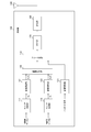
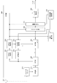
- FIG. 3 is a diagram illustrating a configuration example of the receiver 300 according to the first embodiment of the present technology.
- the receiver 300 includes an antenna 311, a bandpass filter 313, a reception unit 315, an FFT unit 320, a TMCC extraction unit 331, a TMCC demodulation unit 332, an SP extraction unit 333, and a transmission path estimation unit 341.
- the equalizer 345, the deframer 360, the layer divider 370, the amplitude normalizers 381 and 382, and the carrier demodulators 391 and 392 are provided.
- the reception signal received by the antenna 311 is input to the reception unit 315 via the bandpass filter 313.
- the band pass filter 313 is a filter that limits the pass band of the received signal.
- the receiving unit 315 frequency-converts the radio frequency received signal into an intermediate frequency signal, performs quadrature demodulation, and then performs signal processing such as guard interval removal.
- the FFT unit 320 performs a fast Fourier transform (FFT) on the signal processed by the receiving unit 315, and transforms a time domain signal into a frequency domain signal y.
- the frequency domain signal y converted by the FFT unit 320 is output to the TMCC extraction unit 331, the SP extraction unit 333, and the equalization unit 345.
- the FFT unit 320 is an example of the fast Fourier transform unit described in the claims.
- the TMCC extraction unit 331 extracts a transmission control (TMCC: Transmission and Multiplexing Configulation Control) signal from the frequency domain signal from the FFT unit 320.
- This TMCC signal is a signal related to transmission control of a modulated wave, which is necessary for demodulating a received signal.
- the TMCC signal includes information such as a layer to which the signal belongs, power increase/decrease rates Aa and Ab in the amplitude adjusting units 121 and 122 of the transmitter 100, and a band of a broadcast wave.
- the TMCC demodulation unit 332 demodulates the TMCC signal extracted by the TMCC extraction unit 331. By demodulating the TMCC signal by the TMCC demodulation unit 332, it becomes possible to specify the layer included in the received signal, the power increase/decrease rate, the band of the broadcast wave, and other information included in the TMCC signal.
- the TMCC demodulation unit 332 is an example of the transmission control signal acquisition unit described in the claims.
- the SP extraction unit 333 extracts a scattered pilot (SP) signal from the frequency domain signal from the FFT unit 320.
- the SP signal is a pilot signal inserted at a constant interval in the time axis direction and the frequency axis direction for estimating the transmission path.
- the SP signal extracted by the SP extraction unit 333 is supplied to the transmission path estimation unit 341.
- the SP extraction unit 333 is an example of the pilot signal extraction unit described in the claims.
- the transmission path estimation unit 341 estimates the transmission path by interpolating the SP signal extracted by the SP extraction unit 333 in the time axis direction and the frequency axis direction for the layer specified by the TMCC demodulation unit 332.
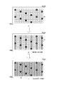
- FIG. 4 is a diagram illustrating a mode example of transmission path estimation by the transmission path estimation unit 341 according to the embodiment of the present technology.
- the transmission path estimation unit 341 obtains the transmission path of the SP signal 30 extracted by the SP extraction unit 333, as indicated by a in the figure.
- the SP signal 30 is divided according to the layer to which the SP signal 30 belongs by referring to the layer specified by the TMCC demodulation unit 332. That is, in the A layer, the SP signal 30 is divided by Aa ⁇ Ssp. On the other hand, in the B layer, the SP signal 30 is divided by Ab ⁇ Ssp. Note that Ssp is the SP signal before the amplitude adjustment by the amplitude adjusting unit 123.
- the transmission path of the data signal 40 is obtained by performing interpolation of the transmission path in the time axis direction.
- the transmission path of the data signal 50 is obtained by interpolating the transmission path in the frequency axis direction.
- the transmission path is estimated by interpolating the SP signal for each layer, and the channel coefficient H is generated.
- the generated channel coefficient H is supplied to the equalization unit 345.
- the equalization unit 345 performs equalization processing based on the signal y from the FFT unit 320 and the channel coefficient H from the transmission path estimation unit 341. That is, each signal y is corrected (y/H) with each channel coefficient H, and the corrected OFDM frame is calculated.
- the output of the equalizer 345 is supplied to the deframer 360. That is, Aa.Sa is supplied for the signal of the A layer, and Ab.Sb is supplied for the signal of the B layer.
- the deframerization section 360 extracts a necessary data signal from the OFDM frame signal from the equalization section 345.
- the data signal extracted by the deframer 360 is supplied to the layer divider 370.
- the layer division unit 370 divides the data signal from the deframerization unit 360 into data signals for each layer.
- the divided data signals are supplied to the amplitude normalization units 381 and 382 of the corresponding layers. That is, Aa ⁇ Sa is supplied to the amplitude normalizing unit 381, and Ab ⁇ Sb is supplied to the amplitude normalizing unit 382.
- the hierarchy division unit 370 is an example of the hierarchy signal acquisition unit described in the claims.
- the amplitude normalization units 381 and 382 normalize the amplitude of the data signal divided by the layer division unit 370 according to the power increase/decrease rate included in the TMCC signal. That is, the amplitude normalization unit 381 divides the signals Aa and Sa from the layer division unit 370 by the power increase/decrease rate Aa and outputs the data signal Sa. Further, amplitude normalization section 382 divides signals Ab and Sb from hierarchical division section 370 by power increase/decrease rate Ab and outputs data signal Sb.
- the carrier demodulation units 391 and 392 are for demodulating the data signal whose amplitude is normalized by the amplitude normalization units 381 and 382. That is, the carrier demodulation unit 391 demodulates the data signal Sa from the amplitude normalization unit 381 and outputs the data a. Further, the carrier demodulation unit 392 demodulates the data signal Sb from the amplitude normalization unit 382 and outputs the data b.
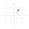
- FIG. 5 is a diagram showing the necessity of amplitude normalization in the embodiment of the present technology.
- 16QAM Quadrature Amplitude Modulation
- This 16QAM is a quadrature phase amplitude modulation system that transmits 16 kinds of values by a 4-bit signal.
- the data signal Sa is originally expected to be demodulated as the position 10. At this time, if the signal of this layer is power-amplified by the power increase/decrease rate Aa in the transmitter 100, it becomes the value of the position 20, and the receiver 300 may be received as a position other than the position 10.
- the amplitude normalization units 381 and 382 normalize the amplitude according to the power increase/decrease rate to remove the influence of power adjustment in the transmitter 100 and reduce the error rate.
- FIG. 6 is a flowchart showing an example of the overall processing procedure of the receiver 300 according to the first embodiment of the present technology.
- the reception signal received by the antenna 311 is input to the reception unit 315 via the bandpass filter 313 (step S901).
- the receiving unit 315 supplies the signal subjected to the signal processing to the FFT unit 320.
- the FFT unit 320 performs a fast Fourier transform process on the signal processed by the receiving unit 315 (step S902).
- the transmission path estimation unit 341 estimates the transmission path by interpolating the SP signal extracted by the SP extraction unit 333 in the time axis direction and the frequency axis direction (step S903). ).
- a necessary data signal is extracted by the deframerization section 360 from the signal of the OFDM frame that has been equalized by the equalization section 345, and divided by the layer division section 370 into data signals for each layer (step). S904).
- the amplitude normalization units 381 and 382 perform amplitude normalization on the data signal for each layer thus obtained (step S905), and the carrier demodulation units 391 and 392 demodulate the data signal (step S906). ..
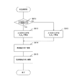
- FIG. 7 is a flowchart showing an example of the processing procedure of the transmission path estimation processing (step S903) in the first embodiment of the present technology.
- the transmission path estimation unit 341 sets the input SP signal to Aa ⁇ Division by Ssp (step S912).
- the input SP signal is the SP signal of the B layer (step S911: No)
- the input SP signal is H ⁇ Ab ⁇ Ssp, and therefore the transmission path estimation unit 341 determines the input SP signal. Division by Ab ⁇ Ssp (step S913).
- the transmission path estimation unit 341 interpolates the SP signal after division in the time axis direction (step S914) and interpolates in the frequency axis direction (step S915). As a result, the transmission path is estimated and the channel coefficient H is generated.
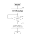
- FIG. 8 is a flowchart showing an example of a processing procedure of the amplitude normalization processing (step S905) according to the first embodiment of the present technology.
- the layer dividing unit 370 converts the input data to the amplitude normalizing unit 381 (“amplitude normalizing unit a” in the figure). Is output) (step S922).
- the amplitude normalization unit 381 divides the input data by Aa and outputs it to the carrier demodulation unit 391 (denoted as “carrier demodulation unit a” in the figure) (step S923).
- the layer dividing unit 370 converts the input data to the amplitude normalizing unit 382 (in the figure, “amplitude normalizing unit”). b”) (step S924).
- the amplitude normalization unit 382 divides the input data by Ab and outputs it to the carrier demodulation unit 392 (denoted as “carrier demodulation unit b” in the figure) (step S925).
- the amplitude normalization unit 381 and 382 of the receiver 300 normalizes the amplitude of the signal whose amplitude has been adjusted in the transmitter 100 for each layer. , The received data signal can be demodulated correctly.
- the two layers of the A layer and the B layer are described as an example, but the same can be applied to the case of three layers or more. The same applies to the following embodiments.
- Second Embodiment> In the above-described first embodiment, it is assumed that the signals of all the layers are received, but an application of receiving only a specific layer is also conceivable. In the second embodiment, the circuit scale and power consumption are reduced by designating the reception layer. Note that the overall configuration of the communication system and the configuration of the transmitter 100 are the same as those in the above-described first embodiment, so detailed description will be omitted.
- FIG. 9 is a figure which shows the structural example of the receiver 300 in 2nd Embodiment of this technique.
- the receiver 300 according to the second embodiment further includes a reception layer designation unit 355 in addition to the above-described first embodiment.
- the transmission path estimation unit 342, the equalization unit 346, the layer division unit 371, and the carrier demodulation unit 393 have different functions from those of the above-described first embodiment. Further, it is not necessary to provide the amplitude normalization units 381 and 382 for each layer. Except for these, the detailed description is omitted because it is the same as that of the first embodiment described above.
- the reception layer designating unit 355 designates a layer to be received according to an instruction from the operator of the receiver 300 or the like.
- the designated layer is supplied to the transmission path estimation unit 342, the layer division unit 371, and the carrier demodulation unit 393.
- the transmission path estimation unit 342 estimates the transmission path by interpolating the SP signal in the time axis direction and the frequency axis direction, as in the above-described first embodiment.
- the operation is performed on the premise.
- the SP signal is divided by Aa ⁇ Ssp in the A layer, and the SP signal is divided by Ab ⁇ Ssp in the B layer.
- the SP signal after the division is multiplied and then the interpolation is performed according to the layer designated as the reception target.
- the equalization unit 346 performs equalization processing as in the above-described first embodiment. However, in the second embodiment, equalization processing is performed based on the signal y from the FFT unit 320 and the output x from the transmission path estimation unit 342. That is, the signal y is corrected (y/x) with the output x, and the corrected OFDM frame is calculated. At this time, the signal y is H.Aa.Sa for the signal of the A layer, and the signal y is H.Ab.Sb for the signal of the B layer. Assuming that the layer designated for reception and the layer of the input signal match, the output of the equalization unit 346 is Sa for the signal of the A layer and Sa for the signal of the B layer. Respectively, Sb is obtained.
- the equalizer 346 in the second embodiment has a function of removing the channel coefficient H, which is the influence of the transmission path, by division, and Aa or Ab (the figure that is the influence of the power increase/decrease rate of the hierarchy designated for reception). It can be considered to have two functions, that is, a function of removing (indicated as A) by division. That is, the equalizing section 346 is equivalent to the equalizing section 345 and the amplitude normalizing section 383 provided at its output section, as compared with the equalizing section 345 of the first embodiment described above.
- the equalization unit 345 has a role of removing the channel coefficient H, which is the influence of the transmission line, by division, and the amplitude normalization unit 383 includes the power increase/decrease rate included in the output of the equalization unit 345 (denoted as y′ in the figure).
- the amplitude normalization unit 383 has the role of removing Aa or Ab, which is the effect of, by division. Therefore, the function of the amplitude normalization unit 383 is included in the equalization unit 346.
- the layer dividing unit 371 divides the data signal from the deframing unit 360 into data signals for each layer, as in the first embodiment described above. However, in the second embodiment, since the layer to be received is designated, only the data signal of the designated layer is divided and supplied to the subsequent stage.
- the hierarchy division unit 371 is an example of the hierarchy signal acquisition unit described in the claims.
- the carrier demodulation unit 393 demodulates the data signal, as in the first embodiment described above. However, in the second embodiment, since the layer to be received is designated, only the data signal of the designated layer is demodulated. Therefore, unlike the above-described first embodiment, one carrier demodulation unit 393 is sufficient. That is, carrier demodulation section 393 demodulates data a from data signal Sa when the designated reception layer is the A layer, and demodulates data b from data signal Sb when the designated reception layer is the B layer.
- FIG. 10 is a flowchart showing an example of a processing procedure of transmission path estimation processing according to the second embodiment of the present technology.
- the transmission path estimation unit 342 determines the input SP signal as Aa ⁇ Division by Ssp (step S932).
- the input SP signal is the SP signal of the B layer (step S931: No)
- the input SP signal is H ⁇ Ab ⁇ Ssp, so the transmission path estimation unit 342 determines the input SP signal. Division by Ab ⁇ Ssp (step S933).
- step S934: Yes If the layer designated to be received by the receiving layer designation unit 355 is layer A (step S934: Yes), the transmission path estimation unit 342 further multiplies the SP signal by Aa (step S935). On the other hand, if the layer designated for reception is the B layer (step S934: No), the transmission path estimation unit 342 further multiplies the SP signal by Ab (step S936).
- the transmission path estimation unit 342 interpolates the obtained SP signal in the time axis direction (step S937) and interpolates in the frequency axis direction (step S938). Thereby, the transmission path is estimated and the output x is generated. That is, the transmission path estimation unit 342 outputs H ⁇ Aa as the output x if the designated reception layer is the A layer, and outputs H ⁇ Ab as the output x if the designated reception layer is the B layer. ..
- the circuit scale and power consumption of the receiver 300 can be reduced by designating the layer to be received by the reception layer designating unit 355.
- Third Embodiment> In the above-described second embodiment, it is assumed that the operator of the receiver 300 or the like specifies the layer to be received, but the layer to be received is determined based on the reception environment of the received signal. May be. In the third embodiment, an example using a modulation error ratio (MER) as an index for measuring the reception environment will be described. Note that the overall configuration of the communication system and the configuration of the transmitter 100 are the same as those in the above-described first embodiment, so detailed description will be omitted.
- MER modulation error ratio
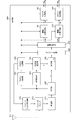
- FIG. 11 is a figure which shows the structural example of the receiver 300 in 3rd Embodiment of this technique.
- the receiver 300 according to the third embodiment includes a MER calculation unit 351 in addition to the above-described second embodiment.
- the other parts are the same as those of the second embodiment described above, and thus detailed description thereof will be omitted.
- the MER calculation unit 351 calculates the modulation error ratio (MER) from the received signal as an index of the reception environment.
- the reception layer designation unit 356 determines the reception environment by using the MER as an index to judge the reception environment.
- the MER calculation unit 351 is an example of the reception environment determination unit described in the claims.
- the reception layer designation unit 356 designates the B layer when it is determined that the reception environment is good using the MER as an index, and designates the A layer when it is determined that the reception environment is bad. As a result, the hierarchy to be received can be specified according to the receiving environment without the operator having to input.
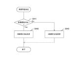
- FIG. 12 is a flowchart showing a processing procedure example of a reception layer designation processing according to the third embodiment of the present technology.
- the MER calculation unit 351 calculates the MER from the received signal.
- the reception layer designation unit 356 determines the reception environment using the MER as an index. If it is determined that the reception environment is good (step S941: Yes), the B layer is designated as the layer to be received (step S942). On the other hand, when it is determined that the reception environment is bad (step S941: No), the layer A is designated as the layer to be received (step S943).
- the reception environment is determined by using the MER calculated by the MER calculation unit 351 as an index, thereby specifying the layer to be received according to the reception environment. be able to.
- MER is used as an index for measuring the reception environment
- an index other than MER may be used as long as the quality of the reception environment can be determined.
- the number of error corrections of the error correction unit, the number of multipaths, the degree of fluctuation of the transmission path, etc. may be used as an index.
- the bandpass filter 313 is used to receive a signal in a predetermined band.
- the occupied band of the received signal may not be known until demodulation, and it is difficult to fix the bandwidth. Therefore, in this modification, the band of the band pass filter 313 is appropriately set to match the occupied band of the received signal. Note that the overall configuration of the communication system and the configuration of the transmitter 100 are the same as those in the above-described first embodiment, so detailed description will be omitted.
- FIG. 13 is a diagram illustrating a configuration example of the receiver 300 in the modification example of the embodiment of the present technology.
- the receiver 300 in this modification includes a bandpass filter control unit 312 in addition to the first embodiment described above. Except for these, the detailed description is omitted because it is the same as that of the first embodiment described above.
- the band pass filter control unit 312 variably controls the signal pass band of the band pass filter 313.
- the bandpass filter control unit 312 sets the bandwidth of the bandpass filter 313 to be narrow so as not to receive a signal in a band more than necessary.
- the bandwidth of the bandpass filter 313 is set wide so that the entire received signal can be received.
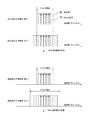
- FIG. 14 is a diagram illustrating a mode example of bandwidth control of the bandpass filter control unit 312 in the modification of the embodiment of the present technology.
- the TMCC signal 70 described above is inserted within the narrowest possible bandwidth of the broadcast wave 60.
- the TMCC signal 70 contains information necessary for demodulation. Although a plurality of TMCC signals 70 are shown, their contents are the same. Therefore, by complementing each other using the plurality of TMCC signals 70, it is possible to complement each other by the portions damaged by noise and perform more reliable reception.
- the band of the bandpass filter 313 may be narrow enough to receive the TMCC signal, regardless of the occupied band of the broadcast wave 60. Since the information of the TMCC signal is necessary for the data demodulation, at this stage, there is no problem even if the band other than the TMCC signal is excluded by the bandpass filter 313.
- the band of the bandpass filter 313 is set in accordance with the occupied band of the broadcast wave 60. Thereby, the band of the bandpass filter 313 can be appropriately set to match the occupied band of the broadcast wave 60.
- FIG. 15 is a flowchart showing an example of a processing procedure of bandpass filter control processing in the modification of the embodiment of the present technology.
- the bandpass filter control unit 312 controls the band of the bandpass filter 313 so as to match the narrowest band of the broadcast wave (step S951).
- the bandpass filter control unit 312 can specify the band of the broadcast wave from the demodulation result of the TMCC signal. Therefore, the bandpass filter 313 can match the band. The band is controlled (step S953).
- the band of the bandpass filter 313 is controlled according to the demodulation result of the TMCC signal, so that the band is appropriately set to match the occupied band of the broadcast wave. be able to. That is, when demodulating the TMCC signal, the band of the bandpass filter is such that noise is minimized regardless of the band of the broadcast wave. Therefore, the demodulation performance of the TMCC signal is improved and the TMCC signal is demodulated accordingly. Higher speed can be expected. Further, since the information of the TMCC signal is required for the data demodulation, even if a part of the broadcast wave is dropped by the bandpass filter before the demodulation of the TMCC signal, there is no problem. On the other hand, after the TMCC demodulation, the band of the bandpass filter is changed to the band that matches the broadcast wave, so that the data can be demodulated.
- the processing procedure described in the above-described embodiment may be regarded as a method having these series of procedures, or as a program for causing a computer to execute the series of procedures or a recording medium storing the program. You can catch it.
- this recording medium for example, a CD (Compact Disc), an MD (MiniDisc), a DVD (Digital Versatile Disc), a memory card, a Blu-ray disc (Blu-ray (registered trademark) Disc), or the like can be used.
- the present technology may have the following configurations.
- a fast Fourier transform unit that performs a fast Fourier transform process on a received signal to generate a fast Fourier transform signal
- An amplitude normalization unit that normalizes the amplitude of the signal for each layer of the fast Fourier transform signal
- a carrier demodulation unit that generates data by performing carrier demodulation on the normalized signal.
- the image processing apparatus further includes a layer signal acquisition unit that acquires a signal for each layer from the fast Fourier transform signal, The receiver according to (3), wherein the amplitude normalization unit performs the normalization by dividing the amplitude of the signal for each layer by a power increase/decrease rate according to the layer.
- a pilot signal extraction unit that extracts a pilot signal from the fast Fourier transform signal
- a transmission path estimation unit that estimates the transmission path by correcting the pilot signal according to the hierarchy and interpolating in the time axis direction and the frequency axis direction, and a transmission path coefficient
- the receiving device further including an equalization unit that corrects the fast Fourier transform signal based on the transmission path coefficient.
- the transmission path estimation unit generates a product of the transmission path coefficient and a power increase/decrease rate of the specified layer according to the specified layer,
- the equalizer corrects the fast Fourier transform signal based on the transmission path coefficient,
- the reception device according to (5), wherein the amplitude normalization unit normalizes the amplitude of the output of the equalization unit based on the power increase/decrease rate of the designated layer.
- the receiving device according to (6), wherein the reception layer designating unit designates the layer to be received according to the determination result of the reception environment determining unit.
- a bandpass filter for limiting the reception band of the received signal A band pass filter control unit that determines a band required for data demodulation based on the transmission control signal and controls the reception band of the reception signal in the band pass filter.
- a communication system including a transmitting device and a receiving device that transmit a signal for each layer via a transmission line
- the transmitter is A carrier modulation unit that performs carrier modulation of data for each layer, An amplitude adjusting unit that increases or decreases the amplitude of the carrier-modulated signal for each layer for each layer, A layer synthesizing unit for synthesizing the signals of the respective layers for which the amplitude is adjusted, An inverse fast Fourier transform unit that generates an inverse fast Fourier transform signal by performing an inverse fast Fourier transform process on the combined signal, A transmitter for transmitting the inverse fast Fourier transform signal,
- the receiving device is A receiver for receiving the signal transmitted from the transmitter, A fast Fourier transform unit that generates a fast Fourier transform signal by performing a fast Fourier transform process on the signal received from the transmitting device, An amplitude normalization unit that normalizes the amplitude of the signal for each layer of the fast Fourier transform signal,
- a communication system comprising: a carrier demodulation unit that demodulates
Landscapes
- Engineering & Computer Science (AREA)
- Signal Processing (AREA)
- Computer Networks & Wireless Communication (AREA)
- Circuits Of Receivers In General (AREA)
- Digital Transmission Methods That Use Modulated Carrier Waves (AREA)
Abstract
Description
1.第1の実施の形態(振幅を正規化してデータを復調する例)
2.第2の実施の形態(受信階層を指定して伝送路を推定する例)
3.第3の実施の形態(受信環境に応じて受信階層を決定して伝送路を推定する例)
4.変形例(バンドパスフィルタの帯域幅を制御する例)
[通信システム]
図1は、本技術の実施の形態における通信システムの全体構成例を示す図である。
R=HS
図2は、本技術の実施の形態における送信機100の構成例を示す図である。
図3は、本技術の第1の実施の形態における受信機300の構成例を示す図である。
y=H・Aa・Sa
であり、B階層の信号の場合は
y=H・Ab・Sb
である。なお、FFT部320は、特許請求の範囲に記載の高速フーリエ変換部の一例である。
図5は、本技術の実施の形態における振幅正規化の必要性を示す図である。
図6は、本技術の第1の実施の形態における受信機300の全体の処理手順例を示す流れ図である。
上述の第1の実施の形態では、全ての階層の信号を受信することを想定していたが、特定の階層のみを受信する用途も考えられる。この第2の実施の形態では、受信階層を指定することにより、回路規模や消費電力の低減を図る。なお、通信システムの全体構成および送信機100の構成については、上述の第1の実施の形態と同様であるため、詳細な説明は省略する。
図9は、本技術の第2の実施の形態における受信機300の構成例を示す図である。
x=H・Aa
となり、受信指定された階層がB階層の場合は
x=H・Ab
となる。
図10は、本技術の第2の実施の形態における伝送路推定処理の処理手順例を示す流れ図である。
上述の第2の実施の形態では、受信対象となる階層を受信機300の操作者などが指定することを想定していたが、受信信号の受信環境に基づいて受信対象となる階層を決定してもよい。この第3の実施の形態では、受信環境を測る指標として、変調誤差比(MER:Modulation Error Ratio)を用いた例について説明する。なお、通信システムの全体構成および送信機100の構成については、上述の第1の実施の形態と同様であるため、詳細な説明は省略する。
図11は、本技術の第3の実施の形態における受信機300の構成例を示す図である。
図12は、本技術の第3の実施の形態における受信階層指定処理の処理手順例を示す流れ図である。
受信機にとって、受信しようとしている信号の帯域外の信号は妨害波となる。そのため、上述の第1乃至第3の実施の形態では、バンドパスフィルタ313を用いて所定の帯域の信号を受信していた。ただし、一般に、受信信号の占有帯域は復調するまで分からないことがあり、帯域幅を固定することは難しい。そこで、この変形例では、バンドパスフィルタ313の帯域を受信信号の占有帯域に合わせるよう適切に設定を行う。なお、通信システムの全体構成および送信機100の構成については、上述の第1の実施の形態と同様であるため、詳細な説明は省略する。
図13は、本技術の実施の形態の変形例における受信機300の構成例を示す図である。
図14は、本技術の実施の形態の変形例におけるバンドパスフィルタ制御部312の帯域幅制御の態様例を示す図である。
図15は、本技術の実施の形態の変形例におけるバンドパスフィルタ制御処理の処理手順例を示す流れ図である。
(1)受信信号を高速フーリエ変換処理して高速フーリエ変換信号を生成する高速フーリエ変換部と、
前記高速フーリエ変換信号の階層毎の信号の振幅を正規化する振幅正規化部と、
前記正規化された信号をキャリア復調してデータを生成するキャリア復調部と
を具備する受信装置。
(2)前記振幅正規化部は、前記階層に応じた電力増減率に基づいて前記正規化を行う
前記(1)に記載の受信装置。
(3)前記高速フーリエ変換信号から伝送制御信号を取得する伝送制御信号取得部をさらに具備し、
前記振幅正規化部は、前記伝送制御信号から前記階層に応じた電力増減率を取得する
前記(2)に記載の受信装置。
(4)前記高速フーリエ変換信号から前記階層毎の信号を取得する階層信号取得部をさらに具備し、
前記振幅正規化部は、前記階層毎の信号の振幅を前記階層に応じた電力増減率によって除算することにより前記正規化を行う
前記(3)に記載の受信装置。
(5)前記高速フーリエ変換信号からパイロット信号を抽出するパイロット信号抽出部と、
前記パイロット信号を前記階層に応じて補正して時間軸方向および周波数軸方向に補間することにより伝送路を推定して伝送路係数を生成する伝送路推定部と、
前記伝送路係数に基づいて前記高速フーリエ変換信号を補正する等化部と
をさらに具備する前記(3)に記載の受信装置。
(6)受信すべき階層を指定する受信階層指定部をさらに具備し、
前記伝送路推定部は、前記指定された階層に応じて前記伝送路係数と前記指定された階層の電力増減率との積を生成し、
前記等化部は、前記伝送路係数に基づいて前記高速フーリエ変換信号を補正し、
前記振幅正規化部は、前記指定された階層の電力増減率に基づいて前記等化部の出力の振幅を正規化する
前記(5)に記載の受信装置。
(7)前記受信信号の受信環境に基づいて前記受信すべき階層を判定する受信環境判定部をさらに具備し、
前記受信階層指定部は、前記受信環境判定部の判定結果に従って前記受信すべき階層を指定する
前記(6)に記載の受信装置。
(8)前記受信信号の受信帯域を制限するバンドパスフィルタと、
前記伝送制御信号に基づいてデータ復調に必要な帯域を判断して前記バンドパスフィルタにおける前記受信信号の受信帯域を制御するバンドパスフィルタ制御部と
をさらに具備する前記(3)から(7)のいずれかに記載の受信装置。
(9)伝送路を介して階層毎の信号を伝送する送信装置および受信装置を具備する通信システムであって、
前記送信装置は、
前記階層毎のデータをキャリア変調するキャリア変調部と、
前記キャリア変調された前記階層毎の信号の振幅を前記階層毎に増減する振幅調整部と、
前記振幅調整された前記階層毎の信号を合成する階層合成部と、
前記合成された信号を逆高速フーリエ変換処理して逆高速フーリエ変換信号を生成する逆高速フーリエ変換部と、
前記逆高速フーリエ変換信号を送信する送信部とを備え、
前記受信装置は、
前記送信装置から送信された信号を受信する受信部と、
前記送信装置から受信した前記信号を高速フーリエ変換処理して高速フーリエ変換信号を生成する高速フーリエ変換部と、
前記高速フーリエ変換信号の階層毎の信号の振幅を正規化する振幅正規化部と、
前記正規化された信号をキャリア復調してデータを生成するキャリア復調部とを備える
通信システム。
(10)高速フーリエ変換部が、受信信号を高速フーリエ変換処理して高速フーリエ変換信号を生成する手順と、
振幅正規化部が、前記高速フーリエ変換信号の階層毎の信号の振幅を正規化する手順と、
キャリア復調部が、前記正規化された信号をキャリア復調してデータを生成する手順と
を具備する受信方法。
111、112 キャリア変調部
121~123 振幅調整部
130 階層合成部
150 フレーム化部
170 IFFT部
180 送信部
190、311 アンテナ
200 伝送路
300 受信機
312 バンドパスフィルタ制御部
313 バンドパスフィルタ
315 受信部
320 FFT部
331 TMCC抽出部
332 TMCC復調部
333 SP抽出部
341、342 伝送路推定部
345、346 等化部
351 MER算出部
355、356 受信階層指定部
360 デフレーム化部
370、371 階層分割部
381~383 振幅正規化部
391~393 キャリア復調部
Claims (10)
- 受信信号を高速フーリエ変換処理して高速フーリエ変換信号を生成する高速フーリエ変換部と、
前記高速フーリエ変換信号の階層毎の信号の振幅を正規化する振幅正規化部と、
前記正規化された信号をキャリア復調してデータを生成するキャリア復調部と
を具備する受信装置。 - 前記振幅正規化部は、前記階層に応じた電力増減率に基づいて前記正規化を行う
請求項1記載の受信装置。 - 前記高速フーリエ変換信号から伝送制御信号を取得する伝送制御信号取得部をさらに具備し、
前記振幅正規化部は、前記伝送制御信号から前記階層に応じた電力増減率を取得する
請求項2記載の受信装置。 - 前記高速フーリエ変換信号から前記階層毎の信号を取得する階層信号取得部をさらに具備し、
前記振幅正規化部は、前記階層毎の信号の振幅を前記階層に応じた電力増減率によって除算することにより前記正規化を行う
請求項3記載の受信装置。 - 前記高速フーリエ変換信号からパイロット信号を抽出するパイロット信号抽出部と、
前記パイロット信号を前記階層に応じて補正して時間軸方向および周波数軸方向に補間することにより伝送路を推定して伝送路係数を生成する伝送路推定部と、
前記伝送路係数に基づいて前記高速フーリエ変換信号を補正する等化部と
をさらに具備する請求項3記載の受信装置。 - 受信すべき階層を指定する受信階層指定部をさらに具備し、
前記伝送路推定部は、前記指定された階層に応じて前記伝送路係数と前記指定された階層の電力増減率との積を生成し、
前記等化部は、前記伝送路係数に基づいて前記高速フーリエ変換信号を補正し、
前記振幅正規化部は、前記指定された階層の電力増減率に基づいて前記等化部の出力の振幅を正規化する
請求項5記載の受信装置。 - 前記受信信号の受信環境に基づいて前記受信すべき階層を判定する受信環境判定部をさらに具備し、
前記受信階層指定部は、前記受信環境判定部の判定結果に従って前記受信すべき階層を指定する
請求項6記載の受信装置。 - 前記受信信号の受信帯域を制限するバンドパスフィルタと、
前記伝送制御信号に基づいてデータ復調に必要な帯域を判断して前記バンドパスフィルタにおける前記受信信号の受信帯域を制御するバンドパスフィルタ制御部と
をさらに具備する請求項3記載の受信装置。 - 伝送路を介して階層毎の信号を伝送する送信装置および受信装置を具備する通信システムであって、
前記送信装置は、
前記階層毎のデータをキャリア変調するキャリア変調部と、
前記キャリア変調された前記階層毎の信号の振幅を前記階層毎に増減する振幅調整部と、
前記振幅調整された前記階層毎の信号を合成する階層合成部と、
前記合成された信号を逆高速フーリエ変換処理して逆高速フーリエ変換信号を生成する逆高速フーリエ変換部と、
前記逆高速フーリエ変換信号を送信する送信部とを備え、
前記受信装置は、
前記送信装置から送信された信号を受信する受信部と、
前記送信装置から受信した前記信号を高速フーリエ変換処理して高速フーリエ変換信号を生成する高速フーリエ変換部と、
前記高速フーリエ変換信号の階層毎の信号の振幅を正規化する振幅正規化部と、
前記正規化された信号をキャリア復調してデータを生成するキャリア復調部とを備える
通信システム。 - 高速フーリエ変換部が、受信信号を高速フーリエ変換処理して高速フーリエ変換信号を生成する手順と、
振幅正規化部が、前記高速フーリエ変換信号の階層毎の信号の振幅を正規化する手順と、
キャリア復調部が、前記正規化された信号をキャリア復調してデータを生成する手順と
を具備する受信方法。
Priority Applications (2)
| Application Number | Priority Date | Filing Date | Title |
|---|---|---|---|
| JP2020558097A JP7432522B2 (ja) | 2018-11-30 | 2019-08-26 | 受信装置、通信システムおよび受信方法 |
| BR112021009881-0A BR112021009881A2 (pt) | 2018-11-30 | 2019-08-26 | dispositivo e método de recepção, e, sistema de comunicação |
Applications Claiming Priority (2)
| Application Number | Priority Date | Filing Date | Title |
|---|---|---|---|
| JP2018224320 | 2018-11-30 | ||
| JP2018-224320 | 2018-11-30 |
Publications (1)
| Publication Number | Publication Date |
|---|---|
| WO2020110388A1 true WO2020110388A1 (ja) | 2020-06-04 |
Family
ID=70852734
Family Applications (1)
| Application Number | Title | Priority Date | Filing Date |
|---|---|---|---|
| PCT/JP2019/033226 Ceased WO2020110388A1 (ja) | 2018-11-30 | 2019-08-26 | 受信装置、通信システムおよび受信方法 |
Country Status (3)
| Country | Link |
|---|---|
| JP (1) | JP7432522B2 (ja) |
| BR (1) | BR112021009881A2 (ja) |
| WO (1) | WO2020110388A1 (ja) |
Citations (7)
| Publication number | Priority date | Publication date | Assignee | Title |
|---|---|---|---|---|
| JPH11145928A (ja) * | 1997-11-04 | 1999-05-28 | Nippon Hoso Kyokai <Nhk> | Ofdm伝送方法、送信装置および受信装置 |
| JP2000101542A (ja) * | 1998-09-24 | 2000-04-07 | Jisedai Digital Television Hoso System Kenkyusho:Kk | 地上デジタル放送方式 |
| JP2005204339A (ja) * | 2005-03-18 | 2005-07-28 | Matsushita Electric Ind Co Ltd | 無線送信装置及びガード周波数帯設定方法 |
| JP2009232439A (ja) * | 2008-02-29 | 2009-10-08 | Sony Corp | 受信装置、受信方法、およびプログラム |
| JP2017527167A (ja) * | 2014-07-03 | 2017-09-14 | エレクトロニクス アンド テレコミュニケーションズ リサーチ インスチチュートElectronics And Telecommunications Research Institute | レイヤードディビジョンマルチプレキシングを利用した信号マルチプレキシング装置および信号マルチプレキシング方法 |
| JP2018029336A (ja) * | 2016-08-15 | 2018-02-22 | 日本放送協会 | Ofdm送受信装置 |
| JP2018050153A (ja) * | 2016-09-21 | 2018-03-29 | 日本放送協会 | Ofdm信号送信装置、ofdm信号受信装置、ofdm信号送信方法、ofdm信号受信方法及びチップ |
Family Cites Families (1)
| Publication number | Priority date | Publication date | Assignee | Title |
|---|---|---|---|---|
| JP2010034854A (ja) | 2008-07-29 | 2010-02-12 | Sharp Corp | 復調装置、復調方法、復調プログラム、及びコンピュータ読み取り可能な記録媒体 |
-
2019
- 2019-08-26 JP JP2020558097A patent/JP7432522B2/ja active Active
- 2019-08-26 WO PCT/JP2019/033226 patent/WO2020110388A1/ja not_active Ceased
- 2019-08-26 BR BR112021009881-0A patent/BR112021009881A2/pt unknown
Patent Citations (7)
| Publication number | Priority date | Publication date | Assignee | Title |
|---|---|---|---|---|
| JPH11145928A (ja) * | 1997-11-04 | 1999-05-28 | Nippon Hoso Kyokai <Nhk> | Ofdm伝送方法、送信装置および受信装置 |
| JP2000101542A (ja) * | 1998-09-24 | 2000-04-07 | Jisedai Digital Television Hoso System Kenkyusho:Kk | 地上デジタル放送方式 |
| JP2005204339A (ja) * | 2005-03-18 | 2005-07-28 | Matsushita Electric Ind Co Ltd | 無線送信装置及びガード周波数帯設定方法 |
| JP2009232439A (ja) * | 2008-02-29 | 2009-10-08 | Sony Corp | 受信装置、受信方法、およびプログラム |
| JP2017527167A (ja) * | 2014-07-03 | 2017-09-14 | エレクトロニクス アンド テレコミュニケーションズ リサーチ インスチチュートElectronics And Telecommunications Research Institute | レイヤードディビジョンマルチプレキシングを利用した信号マルチプレキシング装置および信号マルチプレキシング方法 |
| JP2018029336A (ja) * | 2016-08-15 | 2018-02-22 | 日本放送協会 | Ofdm送受信装置 |
| JP2018050153A (ja) * | 2016-09-21 | 2018-03-29 | 日本放送協会 | Ofdm信号送信装置、ofdm信号受信装置、ofdm信号送信方法、ofdm信号受信方法及びチップ |
Also Published As
| Publication number | Publication date |
|---|---|
| JP7432522B2 (ja) | 2024-02-16 |
| BR112021009881A2 (pt) | 2021-08-17 |
| JPWO2020110388A1 (ja) | 2021-10-14 |
Similar Documents
| Publication | Publication Date | Title |
|---|---|---|
| US8406322B2 (en) | OFDM demodulation device and method | |
| US8750435B2 (en) | Receiving apparatus, receiving method, and receiving system | |
| US20070036232A1 (en) | Ofdm reception apparatus and ofdm reception method | |
| JP3079950B2 (ja) | 直交周波数分割多重変調信号の受信装置及び伝送方法 | |
| US20170118057A1 (en) | Ofdm transmitting and receiving systems and methods thereof | |
| JP3740468B2 (ja) | Ofdm受信装置及びデータ復調方法 | |
| TW201515413A (zh) | 用於傳送和接收信號的發射機和接收機 | |
| JP4173460B2 (ja) | デジタル放送受信装置 | |
| JPWO2017183631A1 (ja) | Los−mimo復調装置、通信装置、los−mimo伝送システム、los−mimo復調方法及びプログラム | |
| US8175204B2 (en) | Receiving device, signal processing method, and program | |
| US8989286B2 (en) | Mapping a transmission stream in a virtual baseband to a physical baseband with equalization | |
| JP2010074417A (ja) | 無線送信機、受信機および無線送信方法 | |
| JP7432522B2 (ja) | 受信装置、通信システムおよび受信方法 | |
| CN104052692B (zh) | 数据信号校正电路、接收器和数据信号校正方法 | |
| JP7782662B2 (ja) | 無線通信方法、無線通信システム、及び送信装置 | |
| JP2018029336A (ja) | Ofdm送受信装置 | |
| JP2002152169A (ja) | 直交周波数分割多重信号受信装置及び直交周波数分割多重信号受信方法 | |
| JP2012023670A (ja) | Ofdm伝送方式における受信機 | |
| JP7720002B2 (ja) | 無線通信方法、無線通信システム、及び送信装置 | |
| JP2008167116A (ja) | 受信装置および方法、並びにプログラム | |
| JP2010141907A (ja) | 受信装置、受信方法、およびプログラム | |
| JP7006892B2 (ja) | 送信回路、送信機器、歪み補正方法 | |
| JP2019068160A (ja) | 信号送受信装置、送信機、受信機、信号送受信装置の制御方法、およびプログラム | |
| JP5068230B2 (ja) | Ofdmデジタル信号等化装置、等化方法及び中継装置 | |
| JP2004140739A (ja) | Ofdm受信装置 |
Legal Events
| Date | Code | Title | Description |
|---|---|---|---|
| 121 | Ep: the epo has been informed by wipo that ep was designated in this application |
Ref document number: 19891628 Country of ref document: EP Kind code of ref document: A1 |
|
| ENP | Entry into the national phase |
Ref document number: 2020558097 Country of ref document: JP Kind code of ref document: A |
|
| NENP | Non-entry into the national phase |
Ref country code: DE |
|
| REG | Reference to national code |
Ref country code: BR Ref legal event code: B01A Ref document number: 112021009881 Country of ref document: BR |
|
| ENP | Entry into the national phase |
Ref document number: 112021009881 Country of ref document: BR Kind code of ref document: A2 Effective date: 20210521 |
|
| 122 | Ep: pct application non-entry in european phase |
Ref document number: 19891628 Country of ref document: EP Kind code of ref document: A1 |