WO2020105595A1 - 燃料噴射システム - Google Patents
燃料噴射システムInfo
- Publication number
- WO2020105595A1 WO2020105595A1 PCT/JP2019/045127 JP2019045127W WO2020105595A1 WO 2020105595 A1 WO2020105595 A1 WO 2020105595A1 JP 2019045127 W JP2019045127 W JP 2019045127W WO 2020105595 A1 WO2020105595 A1 WO 2020105595A1
- Authority
- WO
- WIPO (PCT)
- Prior art keywords
- valve
- fuel
- pressure
- opening
- closing
- Prior art date
- Legal status (The legal status is an assumption and is not a legal conclusion. Google has not performed a legal analysis and makes no representation as to the accuracy of the status listed.)
- Ceased
Links
Images









Classifications
-
- F—MECHANICAL ENGINEERING; LIGHTING; HEATING; WEAPONS; BLASTING
- F02—COMBUSTION ENGINES; HOT-GAS OR COMBUSTION-PRODUCT ENGINE PLANTS
- F02D—CONTROLLING COMBUSTION ENGINES
- F02D41/00—Electrical control of supply of combustible mixture or its constituents
- F02D41/30—Controlling fuel injection
- F02D41/38—Controlling fuel injection of the high pressure type
- F02D41/40—Controlling fuel injection of the high pressure type with means for controlling injection timing or duration
- F02D41/401—Controlling injection timing
-
- F—MECHANICAL ENGINEERING; LIGHTING; HEATING; WEAPONS; BLASTING
- F02—COMBUSTION ENGINES; HOT-GAS OR COMBUSTION-PRODUCT ENGINE PLANTS
- F02D—CONTROLLING COMBUSTION ENGINES
- F02D41/00—Electrical control of supply of combustible mixture or its constituents
- F02D41/30—Controlling fuel injection
- F02D41/38—Controlling fuel injection of the high pressure type
- F02D41/3809—Common rail control systems
- F02D41/3836—Controlling the fuel pressure
-
- F—MECHANICAL ENGINEERING; LIGHTING; HEATING; WEAPONS; BLASTING
- F02—COMBUSTION ENGINES; HOT-GAS OR COMBUSTION-PRODUCT ENGINE PLANTS
- F02D—CONTROLLING COMBUSTION ENGINES
- F02D41/00—Electrical control of supply of combustible mixture or its constituents
- F02D41/02—Circuit arrangements for generating control signals
- F02D41/14—Introducing closed-loop corrections
- F02D41/1401—Introducing closed-loop corrections characterised by the control or regulation method
-
- F—MECHANICAL ENGINEERING; LIGHTING; HEATING; WEAPONS; BLASTING
- F02—COMBUSTION ENGINES; HOT-GAS OR COMBUSTION-PRODUCT ENGINE PLANTS
- F02D—CONTROLLING COMBUSTION ENGINES
- F02D41/00—Electrical control of supply of combustible mixture or its constituents
- F02D41/30—Controlling fuel injection
- F02D41/38—Controlling fuel injection of the high pressure type
- F02D41/3809—Common rail control systems
- F02D41/3836—Controlling the fuel pressure
- F02D41/3845—Controlling the fuel pressure by controlling the flow into the common rail, e.g. the amount of fuel pumped
-
- F—MECHANICAL ENGINEERING; LIGHTING; HEATING; WEAPONS; BLASTING
- F02—COMBUSTION ENGINES; HOT-GAS OR COMBUSTION-PRODUCT ENGINE PLANTS
- F02D—CONTROLLING COMBUSTION ENGINES
- F02D41/00—Electrical control of supply of combustible mixture or its constituents
- F02D41/30—Controlling fuel injection
- F02D41/38—Controlling fuel injection of the high pressure type
- F02D41/3809—Common rail control systems
- F02D41/3836—Controlling the fuel pressure
- F02D41/3863—Controlling the fuel pressure by controlling the flow out of the common rail, e.g. using pressure relief valves
-
- F—MECHANICAL ENGINEERING; LIGHTING; HEATING; WEAPONS; BLASTING
- F02—COMBUSTION ENGINES; HOT-GAS OR COMBUSTION-PRODUCT ENGINE PLANTS
- F02M—SUPPLYING COMBUSTION ENGINES IN GENERAL WITH COMBUSTIBLE MIXTURES OR CONSTITUENTS THEREOF
- F02M47/00—Fuel-injection apparatus operated cyclically with fuel-injection valves actuated by fluid pressure
- F02M47/02—Fuel-injection apparatus operated cyclically with fuel-injection valves actuated by fluid pressure of accumulator-injector type, i.e. having fuel pressure of accumulator tending to open, and fuel pressure in other chamber tending to close, injection valves and having means for periodically releasing that closing pressure
- F02M47/027—Electrically actuated valves draining the chamber to release the closing pressure
-
- F—MECHANICAL ENGINEERING; LIGHTING; HEATING; WEAPONS; BLASTING
- F02—COMBUSTION ENGINES; HOT-GAS OR COMBUSTION-PRODUCT ENGINE PLANTS
- F02M—SUPPLYING COMBUSTION ENGINES IN GENERAL WITH COMBUSTIBLE MIXTURES OR CONSTITUENTS THEREOF
- F02M61/00—Fuel-injectors not provided for in groups F02M39/00 - F02M57/00 or F02M67/00
- F02M61/04—Fuel-injectors not provided for in groups F02M39/00 - F02M57/00 or F02M67/00 having valves, e.g. having a plurality of valves in series
- F02M61/10—Other injectors with elongated valve bodies, i.e. of needle-valve type
-
- F—MECHANICAL ENGINEERING; LIGHTING; HEATING; WEAPONS; BLASTING
- F02—COMBUSTION ENGINES; HOT-GAS OR COMBUSTION-PRODUCT ENGINE PLANTS
- F02M—SUPPLYING COMBUSTION ENGINES IN GENERAL WITH COMBUSTIBLE MIXTURES OR CONSTITUENTS THEREOF
- F02M61/00—Fuel-injectors not provided for in groups F02M39/00 - F02M57/00 or F02M67/00
- F02M61/16—Details not provided for in, or of interest apart from, the apparatus of groups F02M61/02 - F02M61/14
- F02M61/161—Means for adjusting injection-valve lift
-
- F—MECHANICAL ENGINEERING; LIGHTING; HEATING; WEAPONS; BLASTING
- F02—COMBUSTION ENGINES; HOT-GAS OR COMBUSTION-PRODUCT ENGINE PLANTS
- F02M—SUPPLYING COMBUSTION ENGINES IN GENERAL WITH COMBUSTIBLE MIXTURES OR CONSTITUENTS THEREOF
- F02M63/00—Other fuel-injection apparatus having pertinent characteristics not provided for in groups F02M39/00 - F02M57/00 or F02M67/00; Details, component parts, or accessories of fuel-injection apparatus, not provided for in, or of interest apart from, the apparatus of groups F02M39/00 - F02M61/00 or F02M67/00; Combination of fuel pump with other devices, e.g. lubricating oil pump
- F02M63/0012—Valves
- F02M63/0059—Arrangements of valve actuators
- F02M63/0064—Two or more actuators acting on two or more valve bodies
-
- F—MECHANICAL ENGINEERING; LIGHTING; HEATING; WEAPONS; BLASTING
- F02—COMBUSTION ENGINES; HOT-GAS OR COMBUSTION-PRODUCT ENGINE PLANTS
- F02D—CONTROLLING COMBUSTION ENGINES
- F02D41/00—Electrical control of supply of combustible mixture or its constituents
- F02D41/02—Circuit arrangements for generating control signals
- F02D41/14—Introducing closed-loop corrections
- F02D41/1401—Introducing closed-loop corrections characterised by the control or regulation method
- F02D2041/1413—Controller structures or design
- F02D2041/1431—Controller structures or design the system including an input-output delay
-
- F—MECHANICAL ENGINEERING; LIGHTING; HEATING; WEAPONS; BLASTING
- F02—COMBUSTION ENGINES; HOT-GAS OR COMBUSTION-PRODUCT ENGINE PLANTS
- F02D—CONTROLLING COMBUSTION ENGINES
- F02D2200/00—Input parameters for engine control
- F02D2200/02—Input parameters for engine control the parameters being related to the engine
- F02D2200/06—Fuel or fuel supply system parameters
- F02D2200/0602—Fuel pressure
Definitions
- the present disclosure relates to a fuel injection system.
- Patent Document 1 A technology has been proposed in which the injection state of the fuel actually injected from the fuel injection valve is detected and the fuel injection system is controlled with high accuracy (for example, refer to Patent Document 1).
- a fuel pressure sensor that detects the pressure of fuel that fluctuates with fuel injection from the injection hole is attached to the fuel passage from the pressure accumulator to the injection hole of the fuel injection valve, and fluctuations that occur with fuel injection are attached.
- a control device that estimates actual injection start timing and actual injection end timing based on a waveform is disclosed. By using the injection start timing and the injection end timing thus estimated, it is possible to detect the response delay of the fuel injection valve with respect to the injection command signal.
- two opening / closing valves are provided as pressure adjusting valves for adjusting the fuel pressure in the control chamber, and by controlling their drive independently, the inclination of the injection rate of the fuel injected from the injection holes is increased.
- the injection start timing and the injection end timing are simply used. It is impossible to determine which of the two on-off valves causes the response delay of the pressure regulating valve only by estimating In order to realize more appropriate fuel injection control, it is required to sufficiently enhance the driving accuracy of the pressure regulating valve.
- the present disclosure has been made in view of the above problems, and provides a fuel injection system capable of accurately detecting a response delay of a pressure control valve, and further improving the accuracy of fuel injection control.
- the main purpose is that.
- the present disclosure relates to a fuel injection system including a pressure accumulator that stores fuel in a high pressure state, and a fuel injection valve that injects high pressure fuel in the pressure accumulator into a cylinder of an internal combustion engine.
- a first disclosure is that the fuel injection valve is injected by axially moving in accordance with a control chamber to which the high pressure fuel is supplied from the pressure accumulator through a high pressure fuel passage and a fuel pressure inside the control chamber.
- a needle valve that opens a hole to inject fuel and a fuel passage that is connected to the control chamber, and allows and blocks the outflow of fuel from the control chamber to allow fuel pressure inside the control chamber.
- a pressure adjusting valve for adjusting the pressure of the fuel passage, the fuel passage having a first fuel passage having a first orifice, and a second orifice having a second orifice for restricting a flow rate of fuel by a flow passage area different from that of the first orifice.
- a fuel passage, the pressure regulating valve includes a first opening / closing valve arranged in the first fuel passage and a second opening / closing valve arranged in the second fuel passage, and the high pressure fuel passage
- a pressure detection unit for detecting the fuel pressure in the interior
- a drive control unit for controlling the opening and closing of the pressure regulating valve based on the drive command signal output to the fuel injection valve, and the drive command signal After the output, an inflection point of the fuel pressure detected by the pressure detection unit and an acquisition unit that acquires the slope of the fuel pressure after the inflection point appears, and the inflection point acquired by the acquisition unit
- a delay time calculation unit that calculates a response delay time of the pressure control valve with respect to the drive command signal for each of the first opening / closing valve and the second opening / closing valve based on the inclination.
- the behavior of the pressure change of the fuel pressure in the control chamber varies depending on the combination of the open / closed state of the first open / close valve and the open / closed state of the second open / close valve.
- the behavior of the pressure change of the fuel pressure in the high-pressure fuel passage that connects the pressure accumulating container and the control chamber also differs. That is, when the first opening / closing valve is opened and the fuel is discharged from the first fuel passage, and when the second opening / closing valve is opened and the fuel is discharged from the second fuel passage, the control chamber is discharged. The flow rate of the discharged fuel is different, and the change behavior of the fuel pressure in the high pressure fuel passage is different accordingly.
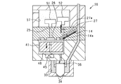
- FIG. 1 is a diagram showing a schematic configuration of a fuel injection system
- FIG. 2 is a diagram showing an example of an injection rate pattern of the fuel injection valve
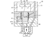
- FIG. 3 is a diagram showing a fuel injection valve when the valve is closed
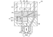
- FIG. 4 is a diagram for explaining the operation of the fuel injection valve in the high speed valve opening mode
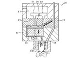
- FIG. 5 is a diagram for explaining the operation of the fuel injection valve when shifting from the high speed valve opening mode to the high speed valve closing mode
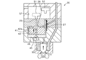
- FIG. 6 is a diagram for explaining the operation of the fuel injection valve in the high speed valve closing mode
- FIG. 1 is a diagram showing a schematic configuration of a fuel injection system
- FIG. 2 is a diagram showing an example of an injection rate pattern of the fuel injection valve
- FIG. 3 is a diagram showing a fuel injection valve when the valve is closed
- FIG. 4 is a diagram for explaining the operation of the fuel injection valve in the high speed valve opening mode
- FIG. 5 is a diagram for explaining the operation of the fuel injection valve when shifting from the high
- FIG. 7 is a diagram for explaining the operation of the fuel injection valve in the low speed valve opening mode
- FIG. 8 is a diagram for explaining the operation of the fuel injection valve when shifting from the low speed valve opening mode to the low speed valve closing mode
- FIG. 9 is a diagram for explaining the operation of the fuel injection valve in the low speed valve closing mode
- FIG. 10 is a diagram showing a pressure reducing operation by the second opening / closing valve
- FIG. 11 is a diagram for explaining the calculation processing of the valve opening delay time
- FIG. 12 is a diagram for explaining the calculation processing of the valve closing delay time
- FIG. 13 is a diagram showing a correspondence relationship between the injection rate mode and the valve opening delay time
- FIG. 14 is a diagram showing a correspondence relationship between the injection rate mode and the valve closing delay time
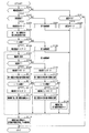
- FIG. 15 is a flowchart showing a processing procedure of response delay time calculation processing
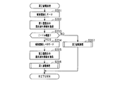
- FIG. 16 is a subroutine of the first energization processing
- FIG. 17 is a subroutine of the second energization processing
- FIG. 18 is a subroutine of the pressure reducing valve mode process.
- the present embodiment is embodied in a fuel injection system applied to an in-vehicle multi-cylinder diesel engine which is an internal combustion engine.
- an electronic control unit hereinafter, referred to as "ECU" is the center for controlling the fuel injection of the engine.
- the fuel injection system 10 includes a common rail 11, a fuel injection valve 20, and an ECU 90.
- the common rail 11 is connected to the downstream side of a high-pressure pump (not shown), and fuel pressurized by the high-pressure pump (hereinafter referred to as “high-pressure fuel”) is supplied. Inside the common rail 11, the high-pressure fuel pumped from the high-pressure pump is held in a high pressure state.
- the common rail 11 is not provided with a pressure reducing valve that lowers the fuel pressure in the common rail (hereinafter referred to as “rail pressure”).
- a fuel injection valve 20 is connected to the common rail 11 via a high-pressure pipe 12.
- the fuel injection valve 20 is a direct injection type that directly injects fuel into the combustion chamber of the engine 70, and is attached to each of a plurality of cylinders (four cylinders in this embodiment). It should be noted that FIG. 1 shows only the fuel injection valve 20 of one cylinder, and the description of the fuel injection valve 20 is omitted for the remaining cylinders.
- the ECU 90 is a microcomputer including a CPU, ROM, RAM, drive circuit, input / output interface, and the like. Detection signals are sequentially input to the ECU 90 from various sensors such as a crank angle sensor that detects a rotation speed of the engine 70 and an accelerator sensor that detects an accelerator operation amount.
- the ECU 90 calculates an optimum fuel injection amount and injection timing based on engine operation information such as engine rotation speed and accelerator operation amount, and outputs a corresponding energization pulse (injection signal) to the fuel injection valve 20. As a result, the fuel injection of the fuel injection valve 20 is controlled in each cylinder.
- the ECU 90 functions as a “drive control unit”, a “delay time calculation unit”, and an “injection correction unit”.
- the fuel injection valve 20 includes first to fourth main body portions 21 to 24, and the first to fourth main body portions 21 to 24 are integrated to form an injection valve main body.
- the first to fourth main body portions 21 to 24 are arranged in this order in the axial direction of the fuel injection valve 20, and the fuel supplied from the common rail 11 to the first main body portion 21 is provided in the fourth main body portion 24. It injects from the injection hole 34.
- the axial direction of the fuel injection valve 20 will be referred to as “vertical direction”
- the first body portion 21 side of the fuel injection valve 20 will be referred to as “upward”
- the fourth body portion 24 side will be referred to as “downward”. ..
- the first main body 21 is provided with a first high pressure passage 13 and a low pressure chamber 57.
- the first high-pressure passage 13 is formed across the first body portion 21, the second body portion 22, and the third body portion 23, and penetrates the first to third body portions 21 to 23.
- the first high-pressure passage 13 is connected to the high-pressure pipe 12 at the end opposite to the second main body 22 side.
- a fuel pressure sensor 73 that detects the pressure of the fuel in the first high pressure passage 13 is attached to the first high pressure passage 13. The detection signal of the fuel pressure sensor 73 is input to the ECU 90.
- the low-pressure chamber 57 is formed at the boundary with the second main body 22 in the first main body 21 by denting the surface facing the second main body 22 upward.
- the high-pressure fuel in the first high-pressure passage 13 passes through the second main body portion 22, the third main body portion 23, and the fourth main body portion 24, and the low-pressure chamber 57 stores the fuel whose pressure has been reduced.
- the low pressure chamber 57 is connected to the return pipe 65 via the low pressure passage 58, and further connected to the fuel tank 61. As a result, part of the high pressure fuel supplied to the fuel injection valve 20 is returned from the low pressure chamber 57 to the fuel tank 61 through the return pipe 65.
- An opening / closing valve 50 that controls the fuel injection state of the fuel injection valve 20 is provided inside the low pressure chamber 57.
- the on-off valve 50 is of an electromagnetic drive type, and the opening and closing of the valve is controlled by the ECU 90.
- the second main body 22 is provided with a second high pressure passage 14, an intermediate chamber 26, a first passage 25, and a second passage 27.
- the second high-pressure passage 14 is a branch passage that branches from the first high-pressure passage 13, and is a fuel passage to which the high-pressure fuel from the common rail 11 is supplied.
- the second high pressure passage 14 is provided with a pressure rising orifice 14a.
- the boost orifice 14a limits the flow rate of the fuel flowing through the second high pressure passage 14.
- an annular chamber 14b is formed at the end portion on the side opposite to the first high pressure passage 13.
- the annular chamber 14b is a fuel passage portion formed in an annular shape in the boundary portion of the second main body portion 22 with the third main body portion 23.
- the high pressure fuel from the first high pressure passage 13 is introduced into the annular chamber 14b through the second high pressure passage 14.
- the intermediate chamber 26 is a cylindrical chamber, and is formed at the boundary between the second main body 22 and the third main body 23.
- the first passage 25 extends in the axial direction (vertical direction) of the fuel injection valve 20 inside the second main body portion 22 and penetrates the second main body portion 22.
- the first passage 25 has one end communicating with the low pressure chamber 57 and the other end communicating with the intermediate chamber 26. As a result, the intermediate chamber 26 communicates with the low pressure chamber 57 via the first passage 25.
- the second passage 27 is formed inside the second main body portion 22 and extends in the same direction (vertical direction) as the first passage 25.
- the second passage 27 penetrates through the second main body 22, one end of which communicates with the low-pressure chamber 57, and the other end of which communicates with the first control chamber 46 of the third main body 23. ..
- a decompression orifice 27 a is provided in the second passage 27 at a position close to the first main body portion 21.
- the pressure reducing orifice 27a limits the flow rate of the fuel flowing through the second passage 27.
- the second passage 27 corresponds to the "second fuel passage"
- the pressure reducing orifice 27a corresponds to the "second orifice”.
- the first body 23 is provided with a first control chamber 46 and a connection passage 47.
- the first control chamber 46 is a chamber formed inside the injection valve body by denting the surface facing the second body portion 22 downward, and is in communication with the annular chamber 14b.
- the high pressure fuel from the first high pressure passage 13 is supplied to the first control chamber 46 via the second high pressure passage 14.
- a driven valve 41 which is displaceable in the axial direction (vertical direction) of the fuel injection valve 20 is arranged.
- the driven valve 41 has a cylindrical shape, and has a third passage 42 formed in the center thereof so as to penetrate therethrough in the axial direction.
- the third passage 42 has an opening on the side of the second main body 22 that is open to the intermediate chamber 26, and an opening on the side of the fourth main body 24 that is open to the inside of the first control chamber 46.
- the third passage 42 is provided with a decompression orifice 42a. The flow rate of the fuel flowing through the third passage 42 is limited by the pressure reducing orifice 42a.
- the fuel flow rate on the outlet side of the pressure reducing orifice 42a is set to be larger than the fuel flow rate on the outlet side of the pressure reducing orifice 27a included in the second passage 27.
- the first passage 25 and the third passage 42 form a “first fuel passage”.
- the decompression orifice 42a corresponds to the "first orifice”.
- a spring 45 is attached to the driven valve 41 to bias the driven valve 41 toward the second main body portion 22 (upward).
- the driven valve 41 is in contact with the lower surface of the second main body portion 22 by the upward force due to the fuel pressure inside the first control chamber 46 and the biasing force of the spring 45.
- the driven valve 41 blocks the communication between the annular chamber 14b and the first control chamber 46, while the intermediate chamber 26 communicates with the first control chamber 46 through the third passage 42.
- the fuel in the first control chamber 46 can flow into the low pressure chamber 57 via the third passage 42, the intermediate chamber 26 and the first passage 25.
- the driven valve 41 In the state where the driven valve 41 is in contact with the lower surface of the second body portion 22, the fuel pressure inside the first control chamber 46 decreases, and the upward force due to the fuel pressure inside the first control chamber 46 and When the biasing force of the spring 45 falls below the downward force due to the fuel pressure inside the annular chamber 14b and the intermediate chamber 26, the driven valve 41 is displaced in the direction away from the lower surface of the second main body portion 22. As a result, the intermediate chamber 26 communicates with the first control chamber 46 without passing through the third passage 42, and the annular chamber 14b communicates with the first control chamber 46.
- the second passage 27 directly connects the low pressure chamber 57 and the first control chamber 46. That is, the first control chamber 46 communicates with the low pressure chamber 57 via the second passage 27 regardless of the position (lifted state) of the driven valve 41. Further, a connection passage 47 extending from the first control chamber 46 to the fourth body portion 24 is formed in the third body portion 23. The connection passage 47 is provided with an orifice 47a, and the orifice 47a limits the flow rate of the fuel flowing through the connection passage 47.
- the fourth body 24 is provided with a cylinder 35, a needle valve 31, a high pressure chamber 33, and a second control chamber 36.
- a plurality of injection holes 34 for injecting fuel toward the outside are formed at the tip of the cylinder 35.
- the needle valve 31 is housed inside the cylinder 35 so as to be capable of reciprocating in the vertical direction.
- a spring 32 that biases the needle valve 31 downward is attached to the upper surface of the needle valve 31.
- the high pressure chamber 33 is provided in the middle of the passage that connects the first high pressure passage 13 and the injection hole 34. Inside the high pressure chamber 33, the tip of the needle valve 31 is arranged.
- the second control chamber 36 is provided inside the cylinder 35 on the side opposite to the injection hole 34 (above the needle valve 31). The second control chamber 36 communicates with the first control chamber 46 via a connection passage 47.
- the high-pressure fuel from the first high-pressure passage 13 is supplied to the second control chamber 36 via the first control chamber 46 and the connection passage 47.
- the fuel pressure inside the second control chamber 36 and the urging force of the spring 32 attached to the needle valve 31 act on the needle valve 31, so that the needle valve 31 closes the injection hole 34 (downward). It is displaced and the fuel injection valve 20 is closed.
- the needle valve 31 opens the injection hole 34 (upward direction). ), The fuel injection valve 20 is opened.
- the fuel injection valve 20 is opened, the high pressure fuel in the high pressure chamber 33 is injected from the injection hole 34.
- the on-off valve 50 is arranged inside the low pressure chamber 57 in the fuel passage that connects the first control chamber 46 and the low pressure chamber 57.
- the on-off valve 50 regulates the fuel pressure inside the first control chamber 46 by allowing and blocking the outflow of fuel from the first control chamber 46 to the low pressure chamber 57 under drive control by the ECU 90.
- the opening / closing valve 50 has a first opening / closing valve 51 and a second opening / closing valve 52.
- the first opening / closing valve 51 is arranged on the first passage 25, and the open / close state thereof is controlled to switch between communication and cutoff between the low pressure chamber 57 and the first passage 25.
- the second opening / closing valve 52 is arranged on the second passage 27, and the open / close state of the second opening / closing valve 52 is controlled to switch the communication between the low pressure chamber 57 and the second passage 27 and the disconnection thereof.
- the ECU 90 independently controls the open / closed state of the first open / close valve 51 and the open / closed state of the second open / close valve 52 by electrically driving the first solenoid 53 and the second solenoid 54 independently of each other.
- the first opening / closing valve 51 when the first solenoid 53 is not energized, the first opening / closing valve 51 is in contact with the second body portion 22 by the urging force of the first spring 55. In this abutting state, the first on-off valve 51 blocks the communication between the low pressure chamber 57 and the first passage 25 (valve closed state).
- the first solenoid 53 is energized while the first opening / closing valve 51 is closed, the first opening / closing valve 51 moves upward against the biasing force of the first spring 55 and is separated from the second main body portion 22. To do. In this state, the low pressure chamber 57 and the first passage 25 are in communication with each other (valve open state), and the fuel is allowed to flow from the first passage 25 into the low pressure chamber 57.
- the second opening / closing valve 52 is in contact with the second body portion 22 by the urging force of the second spring 56. In this abutting state, the communication between the low pressure chamber 57 and the second passage 27 is blocked by the second opening / closing valve 52 (valve closed state). Further, when the second solenoid 54 is energized in the closed state of the second opening / closing valve 52, the second opening / closing valve 52 moves upward against the biasing force of the second spring 56 and is separated from the second main body portion 22. To do. In this state, the low pressure chamber 57 and the second passage 27 are communicated with each other (valve open state), and the inflow of fuel from the second passage 27 into the low pressure chamber 57 is allowed.
- the ECU 90 moves the needle valve 31 to the open position and the closed position by switching the opening and closing of the first opening / closing valve 51.
- the ECU 90 switches the opening / closing of the second opening / closing valve 52 in accordance with the drive control of the first opening / closing valve 51, so that the movement when the needle valve 31 moves to the opening position and the closing position.
- Control the speed That is, the ECU 90 independently controls the opening / closing of the first opening / closing valve 51 and the second opening / closing valve 52 to determine the slope of the fuel injection rate, more specifically, the rising speed and the falling speed of the injection rate. Control each.
- FIG. 2 shows an example of the injection rate pattern of the fuel injection valve 20.
- the first opening / closing valve 51 is opened at the start of fuel injection by the fuel injection valve 20, and the first opening / closing valve 51 is closed at the end of fuel injection.
- the second opening / closing valve 52 is controlled to open and close according to the rising speed and the falling speed of the injection rate.
- the second opening / closing valve 52 is opened (Fig. 2 (a) and (See (c))
- the second opening / closing valve 52 is closed (see FIGS. 2B and 2D).
- the high-speed valve closing mode injection end (H) mode
- the second opening / closing valve 52 is closed (FIGS. 2A and 2B).
- the second on-off valve 52 is opened in the low-speed valve closing mode (injection end (L) mode) in which the falling rate of the injection rate is slowed (see FIGS. 2C and 2D). Further, the rising speed and the falling speed of the injection rate may be changed midway.
- the fuel injection valve 20 for example, as shown in FIG. 2E, an injection rate pattern (injection end (H ⁇ L) mode) for changing from the high speed valve closing mode to the low speed valve closing mode is realized, As shown in 2 (f), it is also possible to realize an injection rate pattern (injection start (L ⁇ H) mode) for changing from the low speed valve opening mode to the high speed valve opening mode.
- the relationship between the open / closed states of the first opening / closing valve 51 and the second opening / closing valve 52 and the operation of the fuel injection valve 20 will be described with reference to FIGS. 3 to 8.
- the first solenoid 53 and the second solenoid 54 are de-energized, so that the first opening / closing valve 51 and the second opening / closing valve 52 are both closed, as shown in FIG.
- the communication between the high pressure chamber 33 and the injection hole 34 is blocked.
- the first control chamber 46 communicates with the low pressure chamber 57 via the first passage 25, the third passage 42, and the second passage 27.
- the fuel inside the first control chamber 46 and the second control chamber 36 passes through two routes, a route passing through the first passage 25 and the third passage 42 and a route passing through the second passage 27. Flow into the low pressure chamber 57.
- the fuel pressure inside the first control chamber 46 and the second control chamber 36 decreases at high speed, and the needle valve 31 is displaced at high speed in the valve opening direction (upward direction). As a result, fuel is injected from the injection hole 34. In this case, the injection rate rises at high speed as shown in FIG.
- a differential pressure is generated before and after the decompression orifice 42a, and the sum of the upward force due to the fuel pressure inside the first control chamber 46 and the biasing force of the spring 45 is the inside of the intermediate chamber 26 and the annular chamber 14b. It is higher than the downward force due to fuel pressure. Therefore, the driven valve 41 is kept in contact with the second main body portion 22 when both the first opening / closing valve 51 and the second opening / closing valve 52 are open (see FIG. 4).
- the fuel in the first control chamber 46 flows into the intermediate chamber 26 via the third passage 42, so that the inside of the intermediate chamber 26 The fuel pressure rises (see FIG. 5). Further, by closing the second opening / closing valve 52, the communication between the low pressure chamber 57 and the first control chamber 46 is cut off. In this case, the downward force due to the fuel pressure inside the intermediate chamber 26 and the annular chamber 14b becomes larger than the total of the upward force due to the fuel pressure inside the first control chamber 46 and the biasing force of the spring 45. As a result, the driven valve 41 moves downward (see FIG. 6). The downward movement of the driven valve 41 causes the high-pressure fuel in the first high-pressure passage 13 to flow into the first control chamber 46.
- the fuel pressure inside the first control chamber 46 rises at a high speed.
- the needle valve 31 starts to descend and closes. The operation shifts (see FIG. 6). In this case, as shown in FIG. 2A, the injection rate falls at a high speed. After that, the injection hole 34 is closed by the needle valve 31, so that the fuel injection by the fuel injection valve 20 is stopped.
- the second opening / closing valve 52 is maintained in the closed state as shown in FIG.
- the on-off valve 51 is opened, the fuel inside the first control chamber 46 flows into the intermediate chamber 26 via the third passage 42 and the first passage 25.
- a differential pressure is generated before and after the decompression orifice 42a, and the sum of the upward force due to the fuel pressure inside the first control chamber 46 and the urging force of the spring 45 is the intermediate chamber 26 and the annular chamber 14b. It is higher than the downward force due to the internal fuel pressure. Therefore, the driven valve 41 is maintained in a state of being in contact with the second main body portion 22.
- the injection rate rises at a low speed. That is, the rate of increase (inclination) of the injection rate when the first opening / closing valve 51 is open and the second opening / closing valve 52 is closed is the injection rate when the first opening / closing valve 51 and the second opening / closing valve 52 are both open. Is smaller than the rising speed (slope) of. After the injection rate reaches the maximum, the operation is the same as the operation at the time of high speed fall shown in FIG.
- the operation at high speed startup is similar to the operation at high speed startup shown in FIG.
- the injection rate reaches the maximum, as shown in FIG. 8, when the second opening / closing valve 52 is maintained in the open state and the first opening / closing valve 51 is closed, the fuel in the first control chamber 46 passes through the third passage. It flows into the intermediate chamber 26 via 42, and the fuel pressure inside the intermediate chamber 26 rises. Further, since the second opening / closing valve 52 is in the open state, the fuel inside the first control chamber 46 flows into the low pressure chamber 57 via the second passage 27.
- the fuel pressure inside the intermediate chamber 26 increases, and the downward force due to the fuel pressure inside the intermediate chamber 26 and the annular chamber 14b causes the upward force due to the fuel pressure inside the first control chamber 46 and the spring 45.
- the driven valve 41 moves downward (see FIG. 9). The downward movement of the driven valve 41 causes the high-pressure fuel in the first high-pressure passage 13 to flow into the first control chamber 46.
- the second opening / closing valve 52 since the second opening / closing valve 52 is maintained in the open state, the fuel pressure inside the first control chamber 46 rises at a low speed.
- the needle valve 31 starts to descend and closes. The operation shifts (see FIG. 9).
- the injection rate falls at a low speed. That is, the rate of decrease (gradient) of the injection rate in the state where the first opening / closing valve 51 is closed and the second opening / closing valve 52 is open is the injection rate in the state where both the first opening / closing valve 51 and the second opening / closing valve 52 are closed. Is smaller than the decreasing speed (slope) of. After that, the injection hole 34 is closed by the needle valve 31, so that the fuel is not injected from the injection hole 34.
- FIG. 10 is a diagram showing an operation in the pressure reducing valve mode in which the second on-off valve 52 reduces the fuel pressure in the common rail 11 without injecting fuel from the fuel injection valve 20.
- the fuel pressure inside the second control chamber 36, the first control chamber 46, and the intermediate chamber 26 is equal to that of the first high-pressure passage 13.
- the fuel pressure is equal to the internal fuel pressure
- the driven valve 41 is in contact with the second body portion 22 (see FIG. 3).
- the second opening / closing valve 52 is opened from this state.
- the fuel in the first control chamber 46 is discharged to the low pressure chamber 57 via the second passage 27, and the driven valve 41 is lowered as the pressure inside the first control chamber 46 decreases. Move in the direction.
- the flow rate of fuel through the pressure increasing orifice 14a is larger than the flow rate of fuel through the pressure reducing orifice 27a. It is set. Therefore, when the first opening / closing valve 51 is closed and the second opening / closing valve 52 is opened, the pressure loss of the fuel discharged from the inside of the first control chamber 46 through the second passage 27 in the second passage 27 is reduced. In this case, the pressure loss of the fuel flowing from the second high pressure passage 14 into the first control chamber 46 becomes larger than the pressure loss in the second high pressure passage 14. Therefore, in the state where the first opening / closing valve 51 is closed and the second opening / closing valve 52 is opened, the needle valve 31 blocks the high pressure chamber 33 from the injection hole 34, that is, fuel is not injected from the injection hole 34. The state is maintained.
- the fuel pressure inside the common rail 11 decreases. That is, the fuel pressure in the common rail 11 is reduced in a state where fuel is not injected from the fuel injection valve 20. Therefore, the fuel injection valve 20 has a function as a pressure reducing valve that reduces the fuel pressure in the common rail 11.
- the driven valve 41 blocks communication between the annular chamber 14b and the first control chamber 46.
- the opening area and the biasing force of the spring 45 are set. That is, when the first passage 25 and the low pressure chamber 57 are communicated with each other by the first opening / closing valve 51, the first control chamber 46 and the intermediate chamber 26 are communicated with each other by the driven valve 41 via the third passage 42. This is achieved by limiting the fuel flow rate by the decompression orifice 42a, the exposed area of the driven valve 41 to the intermediate chamber 26, the exposed area of the driven valve 41 to the first high pressure passage 13, and the biasing force set by the spring 45. ing.
- the first opening / closing valve 51 and Of the second on-off valve 52 the first control is performed when the first on-off valve 51 is open and the second on-off valve 52 is closed and when the second on-off valve 52 is open and the first on-off valve 51 is closed.
- the behavior of changing the fuel pressure inside the chamber 46 is different.
- the behavior of the change in the fuel pressure appears as a difference in the moving speed of the needle valve 31, and further as a pressure change of the fuel in the high pressure fuel passage.
- valve opening delay time Td the time until the first opening / closing valve 51 and the second opening / closing valve 52 are actually opened with the output of the drive command signal.
- the time until the valve is opened (valve closing delay time Te) is divided into the first opening / closing valve 51 and the second opening / closing valve 52 to be calculated.
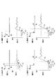
- FIG. 11 is a diagram for explaining the calculation processing of the valve opening delay time Td.
- FIG. 11 shows an example of how the valve opening delay time Td is obtained in the pressure reducing valve mode and each injection rate mode.
- the upper part shows the transition of the energizing pulse of the opening / closing valve 50, of which the solid line shows the first opening / closing valve 51 and the alternate long and short dash line shows the second opening / closing valve 52.
- the lower part shows the transition of the fuel pressure in the high-pressure fuel passage (hereinafter referred to as “detection pressure R”).
- FIG. 11 shows a value obtained by performing a linear approximation by the least square method on the output value of the fuel pressure sensor 73.
- (1-1) Pressure Reducing Valve Mode In the pressure reducing valve mode, as shown in FIG. 11A, the first solenoid 53 is de-energized with the first opening / closing valve 51 and the second opening / closing valve 52 closed. Then, the second solenoid 54 is energized (time t11). When the second opening / closing valve 52 is opened by this energization, the fuel in the first control chamber 46 is discharged to the low pressure chamber 57 via the second passage 27. However, the needle valve 31 remains in the closed position (see FIG. 10). In this case, a pressure drop occurs in the fuel pressure in the first high pressure passage 13, and an inflection point P1 appears in the detected pressure R (time t12).
- the inflection point P1 is caused by the valve opening operation of the second opening / closing valve 52. Therefore, in the pressure reducing valve mode, after the energization pulse is turned on, the inflection point P1 of the pressure decrease is detected by the fuel pressure sensor 73, and from the valve opening command timing (time t11) to the timing (time t12) at which the inflection point P1 appears. Is acquired as the valve opening delay time TdB of the second opening / closing valve 52.
- the inflection point P2 is caused by the valve opening operation of the first opening / closing valve 51. Therefore, in the injection start (L) mode, after the energization pulse is turned on, the inflection point P2 of the pressure drop is detected by the fuel pressure sensor 73, and the inflection point P2 appears (time t21) from the valve opening command timing (time t21). The time until t22) is acquired as the valve opening delay time TdA of the first opening / closing valve 51.
- the inflection point P3 After time t32 when the inflection point P3 appears, the fuel pressure gradually decreases. At this time, when the inclination ⁇ of the pressure drop starting from the inflection point P3 is equivalent to the inclination ⁇ 1 of the pressure reducing valve mode, the inflection point P3 is the second opening / closing valve with the first opening / closing valve 51 closed. It can be determined that 52 is due to switching from the closed valve to the open valve.
- a pressure drop inflection point P4 appears, and the pressure drop slope ⁇ starting from the inflection point P4 is a slope corresponding to the injection start (H) mode.
- H injection start
- the inflection point P (P3, P4) of the pressure drop and the slope ⁇ of the pressure drop are acquired by the fuel pressure sensor 73, and the acquired inflection point P is used to open the valve opening delay time.
- Td the inflection point P (P3, P4) of the pressure drop and the slope ⁇ of the pressure drop
- the acquired inflection point P is used to open the valve opening delay time.
- TdA of the first opening / closing valve 51 and the valve opening delay time TdB of the second opening / closing valve 52 are separated and detected.
- the correspondence relationship between the open / closed states of the first open / close valve 51 and the second open / close valve 52 and the inclination ⁇ is stored in advance, for example, as a specific map. Then, by comparing the correspondence relationship with the inclination ⁇ acquired this time, the inflection point P of the pressure drop acquired by the fuel pressure sensor 73 is determined as the opening of either the first opening / closing valve 51 or the second opening / closing valve 52. Determine if it is due to a valve delay.
- the inclination ⁇ 1 corresponding to the pressure reducing valve mode (the first opening / closing valve 51 is closed and the second opening / closing valve 52 is open)
- the injection start (L) mode (the first opening / closing valve 51 is Three types of inclination ⁇ 2 corresponding to the valve opening and the second opening / closing valve 52 are stored
- the inclination ⁇ 3 corresponding to the injection start (H) mode (both the first opening / closing valve 51 and the second opening / closing valve 52 are open) are stored. It is stored in the department.
- the inclination ⁇ of each mode is stored according to the rail pressure.
- FIG. 11 (d) it is assumed that the first opening / closing valve 51 opens before the second opening / closing valve 52. That is, as shown in FIG. 11D, immediately after time t42 when the pressure drop inflection point P3 is detected by the fuel pressure sensor 73, the inclination ⁇ of the detected pressure R is the inclination ⁇ 2 corresponding to the injection start (L) mode. When it is, it can be determined that the appearance of the inflection point P3 is caused by the opening of the first opening / closing valve 51.
- the inflection point P4 of the pressure drop is detected again, and the inclination ⁇ immediately after the inflection point P4 is detected is the inclination ⁇ 3 corresponding to the injection start (H) mode.
- the time from the valve opening command timing (time t41) to the timing at which the inflection point P3 appears (time t42) is acquired as the valve opening delay time TdA of the first opening / closing valve 51.
- the time from the valve opening command timing (time t41) to the timing (time t43) at which the inflection point P4 appears is acquired as the valve opening delay time TdB of the second opening / closing valve 52.
- (1-4) Injection Start (L ⁇ H) Mode In the injection start (L ⁇ H) mode, when the first opening / closing valve 51 and the second opening / closing valve 52 are closed as shown in FIG. First, the first solenoid 53 is energized (time t51). In addition, after a lapse of a predetermined time from the start of energization of the first solenoid 53, the second solenoid 54 is energized (time t52). The fuel in the first control chamber 46 is discharged to the low pressure chamber 57 with the energization, the needle valve 31 moves, the fuel pressure in the first high pressure passage 13 decreases, and the inflection point P5 first appears in the detected pressure R. (Time t53).
- the inflection point P5 appears when the second opening / closing valve 52 is closed and the first opening / closing is performed. It can be determined that this is due to the valve 51 switching from closed to open.
- the opening delay time TdA of the first opening / closing valve 51 and the opening delay time TdB of the second opening / closing valve 52 are respectively calculated from the inflection points (P5, P6) after turning on the energizing pulse and the inclination ⁇ of the pressure drop. Can be detected.
- the inclination ⁇ 2 corresponding to the injection start (L) mode is first detected after the energization pulse for the opening / closing valve 50 is turned on.
- the time from the output timing (time t51) of the drive command signal to the timing (time t53) at which the inflection point P5 appears is acquired as the valve opening delay time TdA of the first opening / closing valve 51.
- the time from the injection rate mode switching timing (time t52) to the timing at which the inflection point P6 appears (time t54) is acquired as the valve opening delay time TdB of the second opening / closing valve 52.
- the inflection point P7 appears when the second opening / closing valve 51 remains closed. It can be determined that 52 is due to switching from the closed valve to the open valve.
- the inflection point P8 of the pressure drop is detected again, and immediately after the inflection point P8 is detected, the inclination ⁇ is the inclination ⁇ 3 corresponding to the injection start (H) mode.
- the valve opening delay times TdA and TdB can be detected from the inflection points (P7, P8) and the inclination ⁇ that appear after the energization pulse is turned on.
- the inflection point P ⁇ b> 7 changes from the injection start command timing (time t ⁇ b> 61).
- the time until the appearance timing (time t63) is acquired as the valve opening delay time TdB of the second opening / closing valve 52.
- the time from the injection rate mode switching timing (time t62) to the timing at which the inflection point P8 appears (time t64) is acquired as the valve opening delay time TdA of the first opening / closing valve 51.
- FIG. 12 shows an example of an acquisition mode of the valve closing delay time Te at the end of the pressure reducing valve mode and in each injection rate mode. Note that the upper and lower stages in FIG. 12 show the transitions of the energization pulse and the detected pressure R for the first on-off valve 51 and the second on-off valve 52, respectively, as in FIG.
- the inflection point W1 is caused by the valve closing operation of the second opening / closing valve 52. Therefore, at the end of the pressure reducing valve mode, the inflection point W1 is acquired by the fuel pressure sensor 73 after the energization pulse to the second on-off valve 52 is turned off, and the inflection point W1 appears from the valve closing command timing (time t15). The time until (time t16) is acquired as the valve closing delay time TeB of the second opening / closing valve 52.
- the inflection point W2 is caused by the valve closing operation of the first opening / closing valve 51. Therefore, after the pulse is turned off through the passage of the first on-off valve 51, the fuel pressure sensor 73 detects the inflection point W2 of the pressure decrease, and the inflection point W2 appears from the valve closing command timing (time t25) (time t26). ) Is acquired as the valve closing delay time TeA of the first opening / closing valve 51.
- the inflection point W3 is caused by the second opening / closing valve 52 being first switched from the open valve to the closed valve while the first opening / closing valve 51 is open. Therefore, the time from the valve closing command timing (time t35) to the timing at which the inflection point W3 appears (time t36) is acquired as the valve closing delay time TeB of the second opening / closing valve 52.
- the inflection point W4 for pressure recovery is detected, and the inclination ⁇ immediately after the inflection point W4 is the inclination ⁇ 2 corresponding to the injection end (H) mode.
- the time from the valve closing command timing (time t35) to the timing at which the inflection point W4 appears (time t37) is acquired as the valve closing delay time TeA of the first opening / closing valve 51.
- the inflection point W6 When the inflection point W6 appears at time t47 after the inflection point W5 is acquired and the inclination ⁇ after the inflection point W6 is the inclination ⁇ 2 corresponding to the injection end (H) mode, the inflection point W6. It can be determined that the occurrence of the is due to the closing of the second opening / closing valve 52. Therefore, the time from the valve closing command timing (time t45) to the timing at which the inflection point P14 appears (time t47) is acquired as the valve closing delay time TeB of the second opening / closing valve 52.
- the valve closing delay calculating process the correspondence between the open / closed state of each of the first opening / closing valve 51 and the second opening / closing valve 52 and the inclination ⁇ is stored in advance as a specifying map. Then, by comparing the corresponding relationship with the slope ⁇ acquired this time, the inflection point W of the pressure recovery acquired by the fuel pressure sensor 73 is determined by which one of the first on-off valve 51 and the second on-off valve 52 is closed. Determine if it is due to delay.
- the pressure reducing valve mode (when only the second on-off valve 52 is closed from the open state) has a corresponding inclination ⁇ 1
- the injection end (H) mode (the first on-off valve 51 and the second on-off valve 52 are both Three types of inclinations ⁇ 2 corresponding to (closed valve) and an injection end (L) mode (the first opening / closing valve 51 is closed and the second opening / closing valve 52 is opened) are stored in the storage unit.
- the slope ⁇ of each mode is stored according to the rail pressure.
- FIG. 13 shows a correspondence relationship between the injection rate mode and the valve opening delay time Td
- FIG. 14 shows a correspondence relationship between the injection rate mode and the valve closing delay time Te.
- the delay time corresponding to the circled columns in the "valve opening delay detection propriety" and “valve closing delay detection propriety” columns can be detected.
- the valve opening delay time Td and the valve closing delay time are shown. Te can be detected separately for each of the first on-off valve 51 and the second on-off valve 52.
- the valve closing delay time TeB cannot be detected when there is no pressure recovery after pressure reducing.
- step S101 it is determined whether or not there is an injection start request for injecting fuel from the fuel injection valve 20.
- the process proceeds to step S102, and it is determined whether or not the valve opening speed of the needle valve 31 is made high.
- the determination is made based on the engine operating state (engine rotation speed, engine load, etc.). If an affirmative decision is made in step S102, the operation proceeds to step S103, in which injection start (H) mode energization is carried out. Specifically, the first solenoid 53 and the second solenoid 54 are energized simultaneously.
- step S104 the valve opening delay times TdA and TdB of the first on-off valve 51 and the second on-off valve 52 are calculated using the detected pressure R after the energization of the first solenoid 53 and the second solenoid 54 is started.
- the valve opening delay information for calculation information about the inflection point P of the pressure drop and the inclination ⁇ of the pressure drop starting from the inflection point P are acquired (see FIGS. 11C and 11D). ).
- the information about the inflection point P includes the time required from the start of energization until the inflection point P appears.
- step S105 it is determined whether or not the valve opening speed of the needle valve 31 is switched from high speed to low speed on the way to reaching the maximum injection rate. If an affirmative decision is made in step S105, the operation proceeds to step S106, and the energization for the injection start (H ⁇ L) mode is switched. Specifically, the energization of the second solenoid 54 is stopped while the energization of the first solenoid 53 is continued. Then, in step S107, the injection end request is acquired at a timing when a predetermined period has elapsed from the timing of the injection start request. The time from the injection start request to the injection end request is calculated based on the engine operating state (engine rotation speed and engine load) each time.
- step S108 it is determined whether or not the closing speed of the needle valve 31 is made high.
- the process proceeds to step S109, and energization for the injection end (H) mode is performed. Specifically, the energization of the first solenoid 53 and the second solenoid 54 is stopped.
- step S110 as the valve opening delay information for calculating the valve closing delay time TeA of the first opening / closing valve 51 by using the detected pressure R after stopping the energization of the first solenoid 53 and the second solenoid 54, Information about the inflection point W of the pressure recovery is acquired (see FIGS. 12C and 12D).
- the information about the inflection point W includes the time required from the end of energization until the inflection point W appears. At this time, the slope ⁇ of the pressure recovery starting from the inflection point W may also be acquired as the valve opening delay information.
- step S111 it is determined whether or not the closing speed of the needle valve 31 is switched from high speed to low speed on the way to reaching the injection rate of zero. If an affirmative decision is made in step S111, the operation proceeds to step S112, and the energization for the injection end (H ⁇ L) mode is switched. Specifically, the energization of the second solenoid 54 is restarted while the energization of the first solenoid 53 is stopped. After that, in step S113, the energization of the second solenoid 54 is stopped after a predetermined time has elapsed from the resumption of energization of the second solenoid 54, and the process proceeds to step S114. On the other hand, when a negative determination is made in step S111 (that is, when the injection end (H) mode is continued), the process of steps S112 and 113 is not performed and the process proceeds to step S114.
- step S114 the valve opening delay times TdA, TdB, and the valve closing delay time TeA are calculated using the information about the inflection points P, W and the inclinations ⁇ , ⁇ obtained when the fuel injection valve 20 is opened and closed, respectively. Calculate each. Specifically, by using the acquired inclination ⁇ and the specifying map, it is specified which of the first on-off valve 51 and the second on-off valve 52 the inflection point P has caused, and the inflection point is changed. From the information on the point P, the time length of the valve opening delay time Td is calculated. Further, the time length of the valve closing delay time Te is calculated from the information about the inflection point W, and thus the valve opening delay times TdA and TdB and the valve closing delay time TeA are calculated.
- the injection learning value is updated by the calculated valve opening delay times TdA, TdB and the valve closing delay time TeA.
- the updated injection learning value is used to correct the drive command signals for the first opening / closing valve 51 and the second opening / closing valve 52.
- the learning period is set during normal engine operation, and the first opening / closing valve 51 and the second opening / closing valve 51 and the second valve closing delay times TeA, TeB are used by using the plurality of valve opening delay times TdA, TdB and the valve closing delay times TeA, TeB acquired during the learning period.
- the injection learning value of each on-off valve 52 may be calculated.
- step S108 the process proceeds to step S115 to energize for the injection end (L) mode. Specifically, the energization of the first solenoid 53 is stopped and the energization of the second solenoid 54 is restarted.
- step S116 the pressure recovery inflection is used as the valve closing delay information for calculating the valve closing delay time TeA of the first opening / closing valve 51 using the detected pressure R after the energization of the first solenoid 53 is stopped. Information regarding the point W and the slope ⁇ of pressure recovery starting from the inflection point W are acquired.
- step S117 it is determined whether or not the closing speed of the needle valve 31 is switched from low speed to high speed on the way to reaching the injection rate of zero. If an affirmative decision is made in step S117, the operation proceeds to step S118, and the energization for the injection end (L ⁇ H) mode is switched. Specifically, the energization of the second solenoid 54 in addition to the first solenoid 53 is stopped.
- step S119 the detected pressure R after the energization of the second solenoid 54 is stopped is used as the valve closing delay information for calculating the valve closing delay time TeB of the second opening / closing valve 52, and the inflection point of the pressure recovery is set. Information regarding W and the slope ⁇ of pressure recovery starting from the inflection point W are acquired. After that, the process proceeds to step S114, and the response delay time is calculated using the valve opening delay information and the valve closing delay information.
- step S117 when a negative determination is made in step S117, the energization of the second solenoid 54 is stopped after a predetermined time has elapsed from the resumption of energization of the second solenoid 54 (step S120), and the process proceeds to step S114.
- step S105 when a negative determination is made in step S105, that is, when the valve opening speed of the needle valve 31 remains high at the time of starting injection, the process proceeds to step S150, and the first energization process shown in FIG. 16 is performed. Execute a subroutine.
- step S154 the energization of the first solenoid 53 and the second solenoid 54 is stopped as the valve closing delay information for calculating the valve closing delay times TeA and TeB of the first opening / closing valve 51 and the second opening / closing valve 52.
- Information on the inflection point W and the slope ⁇ of the pressure recovery starting from the inflection point W are acquired from the subsequent detected pressure R (see FIGS. 12C and 12D).
- step S152 When a negative determination is made in step S152, the flow proceeds to step S158, and energization for the injection end (L) mode is performed.
- the energization of the first solenoid 53 is stopped while the energization of the second solenoid 54 is continued.
- steps S159 to S163 the same processing as steps S116 to S120 in FIG. 15 described above is executed.
- step S102 when the negative determination is made in step S102, that is, when the valve opening speed of the needle valve 31 is set low in the rising period of the injection rate after the injection start request, the process proceeds to step S200, and FIG. The second energization processing subroutine shown in is executed.
- step S201 energization for the injection start (L) mode is performed.
- the energization of the first solenoid 53 is started while the energization of the second solenoid 54 is stopped.
- step S202 the pressure drop change is used as the valve opening delay information for calculating the valve opening delay time TdA of the first opening / closing valve 51 using the detected pressure R after the energization of the first solenoid 53.
- Information about the bending point P is acquired (see FIG. 11B). At this time, the slope ⁇ of the pressure drop starting from the inflection point P may also be acquired.
- step S203 it is determined whether or not the valve opening speed of the needle valve 31 is switched from low speed to high speed during the time until the injection rate becomes maximum.
- the operation proceeds to step S204, and the energization for the injection start (L ⁇ H) mode is switched.
- energizing the second solenoid 54 is started.
- the change in pressure drop is used as the valve opening delay information for calculating the valve opening delay time TdB of the second opening / closing valve 52 using the detected pressure R after the energization of the second solenoid 54.
- step S206 Information regarding the inflection point P and the slope ⁇ of the pressure drop starting from the inflection point P are acquired (see FIG. 11E). Further, in step S206, the subroutine of the first energization process shown in FIG. 16 is executed. Then, in step S114, the response delay time is calculated. Further, the injection learning value is updated with the calculated response delay time.
- step S203 when a negative determination is made in step S203, the process proceeds to step S207, and the third energization process subroutine is executed.
- the third energization process is a process that is executed when the fuel injection is ended from the state where the first opening / closing valve 51 is open and the state where the second opening / closing valve 52 is closed, and the processing of steps S107 to S120 of FIG. It is composed by. That is, when a negative determination is made in step S203, the same processing as steps S107 to S120 of FIG. 15 is executed. Then, the process of step S114 is executed, and this routine is finished.
- step S101 when the negative determination is made in step S101, that is, when there is no injection start request, the process proceeds to step S121, and it is determined whether or not the common rail 11 is depressurized.
- this routine is finished as it is.
- step S300 the pressure reducing valve mode processing subroutine shown in FIG. 18 is executed.
- step S301 as the energization for the pressure reducing valve mode, the energization of the second solenoid 54 is started while the energization of the first solenoid 53 is stopped.
- step S302 the pressure drop inflection is used as valve opening delay information for calculating the valve opening delay time TdB of the second opening / closing valve 52 using the detected pressure R after the energization of the second solenoid 54 is started.
- Information about the point P and the slope ⁇ of the pressure drop starting from the inflection point P are acquired (see FIG. 11A).
- step S303 a decompression end request is input when the common rail pressure drops to the target pressure. If there is a pressure reduction termination request, the energization of the second solenoid 54 is stopped in step S304, and the pressure reduction valve mode is terminated.
- step S305 an inflection point of pressure recovery is used as valve closing delay information for calculating the valve closing delay time TeB of the second opening / closing valve 52 using the detected pressure R after the energization of the second solenoid 54 is stopped. The information about W and the slope ⁇ of the pressure recovery starting from the inflection point W are acquired (see FIG. 12A). Then, the process returns to the main routine of FIG. 15 to execute the process of step S114.
- a response delay time of the opening / closing valve 50 with respect to the drive command signal is calculated for each of the first opening / closing valve 51 and the second opening / closing valve 52.
- the response delay of the pressure regulating valve can be detected with high accuracy, and the accuracy of the fuel injection system can be further improved.
- the inflection point P is caused by the opening of either the first opening / closing valve 51 or the second opening / closing valve 52. Then, the valve opening delay time Td was calculated. Similarly, using the inclination ⁇ starting from the inflection point W of pressure recovery, which of the first on-off valve 51 and the second on-off valve 52 is the inflection point W caused by? The valve closing delay time Te was calculated by specifying With such a configuration, the response delay time of the first on-off valve 51 and the response delay time of the second on-off valve 52 can be separately detected by the detection value of one fuel pressure sensor 73.
- the decompression start timing and decompression end timing cannot be controlled accurately in the pressure reducing valve mode, rail pressure cannot be controlled accurately, and there is concern that inconveniences such as excessive output or insufficient output, emissions, and deterioration of fuel economy may occur.
- the response delay of the second opening / closing valve 52 is accurately reflected to drive and control the second opening / closing valve 52. can do. As a result, it is possible to improve the accuracy of the decompression start timing and the decompression end timing.
- the drive command signals are corrected for each of the first opening / closing valve 51 and the second opening / closing valve 52. Accordingly, it is possible to improve the accuracy of the drive start timing and the drive end timing of each of the first opening / closing valve 51 and the second opening / closing valve 52.
- the fuel pressure sensor 73 may be attached at any position in the high-pressure fuel passage as long as the pressure changes in conjunction with the pressure change in the first control chamber 46 that accompanies the drive of the opening / closing valve 50. Not limited. For example, it may be provided at the position of the second main body portion 22 or the third main body portion 23 in the first high pressure passage 13. Alternatively, it may be provided in the second high-pressure passage 14 on the upstream side of the pressurizing orifice 14a.
- the configuration of the fuel injection valve 20 is not limited to the configuration shown in FIG.
- the second passage 27 is formed inside the driven valve 41 and the third passage 27 is formed. It may be configured to communicate with the first control chamber 46 via a passage different from the passage 42.
- the second passage 27 communicates with the intermediate chamber 26 and the driven valve 41 blocks the first high pressure passage 13 and the first control chamber 46
- the second passage 27 connects the intermediate chamber 26 and the third passage 42. It may be configured to communicate with the first control chamber 46 via the.
- the moving speed of the needle valve 31 may be adjusted with higher accuracy.
- the flow rate of the fuel through the pressure increasing orifice 14a is set to be larger than the total of the flow rates of the fuel through the pressure reducing orifices provided in the fuel passages of the two or more on-off valves.
- control unit and the method described in the present disclosure are provided by a dedicated computer provided by configuring a processor and a memory programmed to execute one or more functions embodied by a computer program, May be realized.
- control unit and the method described in the present disclosure may be realized by a dedicated computer provided by configuring a processor with one or more dedicated hardware logic circuits.
- control unit and the method thereof described in the present disclosure are based on a combination of a processor and a memory programmed to execute one or more functions and a processor configured by one or more hardware logic circuits. It may be implemented by one or more dedicated computers configured.
- the computer program may be stored in a computer-readable non-transition tangible recording medium as an instruction executed by a computer.
Landscapes
- Engineering & Computer Science (AREA)
- Chemical & Material Sciences (AREA)
- Combustion & Propulsion (AREA)
- Mechanical Engineering (AREA)
- General Engineering & Computer Science (AREA)
- Physics & Mathematics (AREA)
- Fluid Mechanics (AREA)
- Fuel-Injection Apparatus (AREA)
- Electrical Control Of Air Or Fuel Supplied To Internal-Combustion Engine (AREA)
- Combined Controls Of Internal Combustion Engines (AREA)
Abstract
燃料噴射システム(10)は、蓄圧容器(11)内の高圧燃料を内燃機関(70)の気筒内に噴射する燃料噴射弁(20)を備える。燃料噴射システム(10)は、高圧燃料通路(13,14)内の燃料圧力を検出する圧力検出部と、燃料噴射弁(20)に出力された駆動指令信号に基づいて、圧力調整弁(51,52)の開弁及び閉弁を制御する駆動制御部と、前記駆動指令信号の出力後において、前記圧力検出部により検出した燃料圧力の変曲点と、前記変曲点が現れた後の燃料圧力の傾きとを取得する取得部と、前記取得部により取得した前記変曲点と前記傾きとに基づいて、前記駆動指令信号に対する前記圧力調整弁の応答遅れ時間を第1開閉弁(51)及び第2開閉弁(52)のそれぞれについて算出する遅れ時間算出部と、を備える。
Description
本出願は、2018年11月19日に出願された日本特許出願番号2018-216792号に基づくもので、ここにその記載内容を援用する。
本開示は、燃料噴射システムに関する。
燃料噴射弁から実際に噴射された燃料の噴射状態を検出し、燃料噴射システムを高精度に制御する技術が提案されている(例えば、特許文献1参照)。特許文献1には、蓄圧容器から燃料噴射弁の噴射孔に至るまでの燃料通路に、噴射孔からの燃料噴射に伴い変動する燃料の圧力を検出する燃圧センサを取り付け、燃料噴射に伴い生じる変動波形に基づいて実際の噴射開始時期及び噴射終了時期を推定する制御装置が開示されている。こうして推定された噴射開始時期及び噴射終了時期を用いることにより、噴射指令信号に対する燃料噴射弁の応答遅れを検出することが可能である。
燃料噴射弁としては、制御室内の燃料圧力を調整する圧力調整弁として2個の開閉弁を備え、それらの駆動を独立して制御することにより、噴射孔から噴射される燃料の噴射率の傾きを調整するものがある。こうした燃料噴射弁において、上記特許文献1に記載のもののように、燃圧センサの検出値を用いて噴射指令信号に対する燃料噴射弁の応答遅れを検出しようとした場合、単に噴射開始時期及び噴射終了時期を推定するだけでは、圧力調整弁の応答遅れが、2個の開閉弁のうちいずれによるものか判別することができない。より適切な燃料噴射制御を実現するために、圧力調整弁の駆動の精度を十分に高めることが要求される。
本開示は、上記課題に鑑みてなされたものであり、圧力調整弁の応答遅れを精度良く検出することができ、ひいては燃料噴射制御の更なる精度向上を図ることができる燃料噴射システムを提供することを主たる目的とする。
上記課題を解決するために、以下の手段を採用した。
本開示は、燃料を高圧状態で蓄える蓄圧容器と、前記蓄圧容器内の高圧燃料を内燃機関の気筒内に噴射する燃料噴射弁とを備える燃料噴射システムに関する。第1の開示は、前記燃料噴射弁は、前記蓄圧容器から高圧燃料通路を通じて前記高圧燃料が供給される制御室と、前記制御室の内部の燃料圧力に応じて軸方向に移動することにより噴射孔を開弁して燃料を噴射させるニードル弁と、前記制御室に接続される燃料通路に配置され、前記制御室からの燃料の流出を許容及び遮断することにより前記制御室の内部の燃料圧力を調整する圧力調整弁と、を備え、前記燃料通路は、第1オリフィスを有する第1燃料通路と、前記第1オリフィスと異なる流路面積によって燃料の流量を制限する第2オリフィスを有する第2燃料通路と、を備え、前記圧力調整弁は、前記第1燃料通路に配置された第1開閉弁と、前記第2燃料通路に配置された第2開閉弁と、を備え、前記高圧燃料通路内の燃料圧力を検出する圧力検出部と、前記燃料噴射弁に出力された駆動指令信号に基づいて、前記圧力調整弁の開弁及び閉弁を制御する駆動制御部と、前記駆動指令信号の出力後において、前記圧力検出部により検出した燃料圧力の変曲点と、前記変曲点が現れた後の燃料圧力の傾きとを取得する取得部と、前記取得部により取得した前記変曲点と前記傾きとに基づいて、前記駆動指令信号に対する前記圧力調整弁の応答遅れ時間を前記第1開閉弁及び前記第2開閉弁のそれぞれについて算出する遅れ時間算出部と、を備える。
上記構成の燃料噴射弁においては、第1開閉弁の開閉状態及び第2開閉弁の開閉状態の組み合わせに応じて、制御室内の燃料圧力の圧力変化の挙動が異なる。この場合、蓄圧容器と制御室とを接続する高圧燃料通路内の燃料圧力の圧力変化の挙動も異なる。すなわち、第1開閉弁が開弁されて第1燃料通路から燃料が排出される場合と、第2開閉弁が開弁されて第2燃料通路から燃料が排出される場合とでは、制御室から排出される燃料の流量が相違し、これに付随して高圧燃料通路内の燃料圧力の変化挙動が相違する。こうした点に着目し上記構成とすることにより、圧力調整弁の応答遅れがいずれの開閉弁によるものかを特定することができる。これにより、圧力調整弁の応答遅れを精度良く検出することができ、ひいては、燃料噴射システムの更なる精度向上を図ることができる。
本開示についての上記目的およびその他の目的、特徴や利点は、添付の図面を参照しながら下記の詳細な記述により、より明確になる。その図面は、
図1は、燃料噴射システムの概略構成を示す図であり、
図2は、燃料噴射弁の噴射率パターンの一例を示す図であり、
図3は、閉弁時の燃料噴射弁を表す図であり、
図4は、高速開弁モードの燃料噴射弁の動作を説明する図であり、
図5は、高速開弁モードから高速閉弁モードへ移行するときの燃料噴射弁の動作を説明する図であり、
図6は、高速閉弁モードの燃料噴射弁の動作を説明する図であり、
図7は、低速開弁モードの燃料噴射弁の動作を説明する図であり、
図8は、低速開弁モードから低速閉弁モードへ移行するときの燃料噴射弁の動作を説明する図であり、
図9は、低速閉弁モードの燃料噴射弁の動作を説明する図であり、
図10は、第2開閉弁による減圧動作を示す図であり、
図11は、開弁遅れ時間の算出処理を説明する図であり、
図12は、閉弁遅れ時間の算出処理を説明する図であり、
図13は、噴射率モードと開弁遅れ時間との対応関係を示す図であり、
図14は、噴射率モードと閉弁遅れ時間との対応関係を示す図であり、
図15は、応答遅れ時間算出処理の処理手順を示すフローチャートであり、
図16は、第1通電処理のサブルーチンであり、
図17は、第2通電処理のサブルーチンであり、
図18は、減圧弁モード処理のサブルーチンである。
以下、実施形態について図面を参照しつつ説明する。なお、以下の各実施形態の相互において、互いに同一又は均等である部分には図中、同一符号を付しており、同一符号の部分についてはその説明を援用する。
本実施形態は、内燃機関である車載多気筒ディーゼルエンジンに適用される燃料噴射システムに具体化している。この燃料噴射システムでは、電子制御ユニット(以下、「ECU」という。)を中枢としてエンジンの燃料噴射を制御している。図1に示すように、燃料噴射システム10は、コモンレール11、燃料噴射弁20及びECU90を備える。
図1において、コモンレール11は、図示しない高圧ポンプの下流側に接続されており、高圧ポンプで高圧化された燃料(以下「高圧燃料」という。)が供給される。コモンレール11の内部には、高圧ポンプから圧送された高圧燃料が高圧状態で保持される。コモンレール11には、コモンレール内の燃料圧力(以下「レール圧」という。)を低下させる減圧弁が設けられていない。
コモンレール11には、高圧配管12を介して燃料噴射弁20が接続されている。燃料噴射弁20は、エンジン70の燃焼室内に燃料を直接噴射する直噴式であり、複数の気筒(本実施形態では4気筒)のそれぞれに取り付けられている。なお、図1には、1つの気筒の燃料噴射弁20のみを示し、残りの気筒については燃料噴射弁20の記載を省略している。
ECU90は、CPU、ROM、RAM、駆動回路、入出力インターフェース等を含むマイクロコンピュータである。ECU90には、エンジン70の回転速度を検出するクランク角センサ、アクセル操作量を検出するアクセルセンサ等の各種センサから検出信号が逐次入力される。ECU90は、エンジン回転速度やアクセル操作量等のエンジン運転情報に基づいて最適な燃料噴射量及び噴射時期を算出し、それに応じた通電パルス(噴射信号)を燃料噴射弁20に出力する。これにより、各気筒において、燃料噴射弁20の燃料噴射が制御される。なお、ECU90が「駆動制御部」、「遅れ時間算出部」及び「噴射補正部」として機能する。
次に、燃料噴射弁20の構成について詳細に説明する。燃料噴射弁20は、第1~第4本体部21~24を備え、これら第1~第4本体部21~24が一体化されることにより噴射弁本体が構成されている。第1~第4本体部21~24は、燃料噴射弁20の軸方向にこの順に並べて配置されており、コモンレール11から第1本体部21に供給された燃料を、第4本体部24に設けられた噴射孔34から噴射する。なお、以下の説明では、燃料噴射弁20の軸方向を「上下方向」、燃料噴射弁20における第1本体部21側を「上方向」、第4本体部24側を「下方向」とする。
第1本体部21には、第1高圧通路13と、低圧室57とが設けられている。第1高圧通路13は、第1本体部21、第2本体部22及び第3本体部23に亘って形成されており、第1~第3本体部21~23を貫通している。第1高圧通路13は、第2本体部22側とは反対側の端部が高圧配管12に連通されている。これにより、コモンレール11からの高圧燃料が高圧配管12を介して第1高圧通路13に供給される。第1高圧通路13には、第1高圧通路13内の燃料の圧力を検出する燃圧センサ73が取り付けられている。燃圧センサ73の検出信号はECU90に入力される。
低圧室57は、第2本体部22を向いた面が上方向に凹むことにより、第1本体部21において第2本体部22との境界部に形成されている。低圧室57には、第1高圧通路13内の高圧燃料が第2本体部22、第3本体部23及び第4本体部24を経由し、これにより低圧化された燃料が収容されている。低圧室57は、低圧通路58を介してリターン配管65に接続されており、更に燃料タンク61に接続されている。これにより、燃料噴射弁20に供給される高圧燃料の一部は、低圧室57からリターン配管65を通じて燃料タンク61に戻される。低圧室57の内部には、燃料噴射弁20の燃料の噴射状態を制御する開閉弁50が設けられている。開閉弁50は電磁駆動式であり、ECU90により開弁及び閉弁が制御される。
第2本体部22には、第2高圧通路14と、中間室26と、第1通路25と、第2通路27とが設けられている。第2高圧通路14は、第1高圧通路13から分岐する分岐路であり、コモンレール11からの高圧燃料が供給される燃料通路である。第2高圧通路14には、昇圧オリフィス14aが設けられている。この昇圧オリフィス14aにより、第2高圧通路14を流れる燃料の流量が制限される。第2高圧通路14において、第1高圧通路13とは反対側の端部には環状室14bが形成されている。環状室14bは、第2本体部22において第3本体部23との境界部に環状に形成された燃料通路部である。環状室14bには、第1高圧通路13からの高圧燃料が第2高圧通路14を通じて導入される。
中間室26は、円柱状に形成されたチャンバであり、第2本体部22と第3本体部23との境界部に形成されている。第1通路25は、第2本体部22の内部において燃料噴射弁20の軸方向(上下方向)に延びており、第2本体部22を貫通している。第1通路25は、その一方の端部が低圧室57に連通され、他方の端部が中間室26に連通されている。これにより、中間室26は、第1通路25を介して低圧室57に連通されている。
第2通路27は、第2本体部22の内部に形成されており、第1通路25と同じ方向(上下方向)に延びている。第2通路27は第2本体部22を貫通しており、その一方の端部が低圧室57に連通され、他方の端部が第3本体部23の第1制御室46に連通されている。第2通路27には、第1本体部21に近い位置に減圧オリフィス27aが設けられている。減圧オリフィス27aにより第2通路27を流れる燃料の流量が制限される。なお、第2通路27が「第2燃料通路」に相当し、減圧オリフィス27aが「第2オリフィス」に相当する。
第3本体部23には、第1制御室46と、接続通路47とが設けられている。第1制御室46は、第2本体部22を向いた面が下方向に凹むことにより噴射弁本体の内部に形成されたチャンバであり、環状室14bに連通されている。第1制御室46には、第1高圧通路13からの高圧燃料が第2高圧通路14を介して供給される。
第1制御室46の内部には、燃料噴射弁20の軸方向(上下方向)に変位可能な従動弁41が配置されている。従動弁41は円柱状であり、その中央部において軸方向に貫通する第3通路42が形成されている。第3通路42は、第2本体部22側の開口部が中間室26に開放されており、第4本体部24側の開口部が第1制御室46の内部に開放されている。第3通路42には減圧オリフィス42aが設けられている。減圧オリフィス42aによって第3通路42を流れる燃料の流量が制限される。減圧オリフィス42aの出口側の燃料流量は、第2通路27が有する減圧オリフィス27aの出口側の燃料流量よりも大きく設定されている。なお、第1通路25及び第3通路42により「第1燃料通路」が構成されている。減圧オリフィス42aが「第1オリフィス」に相当する。
従動弁41には、従動弁41を第2本体部22に向かう方向(上方向)へ付勢するスプリング45が取り付けられている。従動弁41は、第1制御室46の内部の燃料圧力による上方向の力及びスプリング45の付勢力により第2本体部22の下面に当接している。この当接状態では、従動弁41によって環状室14bと第1制御室46との連通は遮断される一方、中間室26は第3通路42を介して第1制御室46に連通された状態となる。この状態では、第1制御室46内の燃料は、第3通路42、中間室26及び第1通路25を介して低圧室57に流入可能である。
従動弁41が第2本体部22の下面に当接している状態において、第1制御室46の内部の燃料圧力が低下して、第1制御室46の内部の燃料圧力による上方向の力及びスプリング45の付勢力が、環状室14b及び中間室26の内部の燃料圧力による下方向の力を下回ると、従動弁41が第2本体部22の下面から離間する方向に変位する。これにより、中間室26が第3通路42を介さずに第1制御室46に連通されるとともに、環状室14bが第1制御室46に連通される。
第2通路27は、低圧室57と第1制御室46とを直接連通している。つまり、第1制御室46は、従動弁41の位置(リフト状態)に依らずに第2通路27を介して低圧室57に連通されている。また、第3本体部23には、第1制御室46から第4本体部24へ延びる接続通路47が形成されている。接続通路47にはオリフィス47aが設けられており、オリフィス47aによって接続通路47を流れる燃料の流量が制限される。
第4本体部24には、シリンダ35と、ニードル弁31と、高圧室33と、第2制御室36とが設けられている。シリンダ35の先端部には、外部に向かって燃料が噴射される噴射孔34が複数形成されている。ニードル弁31は、シリンダ35の内部において上下方向に往復動可能に収容されている。ニードル弁31の上面には、ニードル弁31を下方向へ付勢するスプリング32が取り付けられている。
高圧室33は、第1高圧通路13と噴射孔34とを連通する通路の途中に設けられている。この高圧室33の内部に、ニードル弁31の先端部が配置されている。第2制御室36は、シリンダ35の内部において噴射孔34とは反対側(ニードル弁31の上方)に設けられている。第2制御室36は、接続通路47を介して第1制御室46に連通されている。これにより、第1高圧通路13からの高圧燃料が、第1制御室46及び接続通路47を介して第2制御室36に供給される。第2制御室36の内部の燃料圧力と、ニードル弁31に取り付けられたスプリング32の付勢力とがニードル弁31に作用することにより、ニードル弁31が噴射孔34を塞ぐ方向(下方向)に変位し、燃料噴射弁20が閉弁状態となる。
また、高圧室33の内部の燃料圧力が、第2制御室36の内部の燃料圧力及びスプリング32の付勢力の合計の力よりも大きくなると、ニードル弁31が噴射孔34を開く方向(上方向)に変位し、燃料噴射弁20が開弁状態となる。燃料噴射弁20が開弁状態となることにより、高圧室33内の高圧燃料が噴射孔34から噴射される。
次に、開閉弁50の構成について説明する。開閉弁50は、低圧室57の内部において、第1制御室46と低圧室57とを接続する燃料通路に配置されている。開閉弁50は、ECU90により駆動制御により第1制御室46から低圧室57への燃料の流出を許容及び遮断することにより、第1制御室46の内部の燃料圧力を調整する。
開閉弁50は、第1開閉弁51と、第2開閉弁52とを有している。第1開閉弁51は、第1通路25上に配置されており、その開閉状態が制御されることにより低圧室57と第1通路25との連通及び遮断を切り替える。第2開閉弁52は、第2通路27上に配置されており、その開閉状態が制御されることにより低圧室57と第2通路27との連通及び遮断を切り替える。ECU90は、第1ソレノイド53と第2ソレノイド54とを互いに独立して通電駆動することにより、第1開閉弁51の開閉状態と第2開閉弁52の開閉状態とを互いに独立して制御する。
具体的には、第1ソレノイド53の非通電時には、第1開閉弁51は、第1スプリング55の付勢力により第2本体部22に当接している。この当接状態では、第1開閉弁51により低圧室57と第1通路25との連通が遮断された状態(閉弁状態)となる。また、第1開閉弁51の閉弁状態において第1ソレノイド53に通電すると、第1スプリング55の付勢力に抗して第1開閉弁51が上方向に移動し、第2本体部22から離間する。この状態では、低圧室57と第1通路25とが連通された状態(開弁状態)となり、第1通路25から低圧室57への燃料の流入が許容される。
また、第2ソレノイド54の非通電時には、第2開閉弁52は、第2スプリング56の付勢力により第2本体部22に当接している。この当接状態では、第2開閉弁52により低圧室57と第2通路27との連通が遮断された状態(閉弁状態)となる。また、第2開閉弁52の閉弁状態において第2ソレノイド54に通電すると、第2スプリング56の付勢力に抗して第2開閉弁52が上方向に移動し、第2本体部22から離間する。この状態では、低圧室57と第2通路27とが連通された状態(開弁状態)となり、第2通路27から低圧室57への燃料の流入が許容される。
燃料噴射制御において、ECU90は、第1開閉弁51の開弁及び閉弁を切り替えることにより、ニードル弁31を開弁位置及び閉弁位置に移動させる。これにより、噴射孔34から燃料が噴射される噴射動作と、燃料の噴射が停止される噴射停止動作とが切り替えられる。また、ECU90は、第1開閉弁51の駆動制御に併せて、第2開閉弁52の開弁及び閉弁を切り替えることにより、ニードル弁31が開弁位置及び閉弁位置に移動するときの移動速度を制御する。すなわち、ECU90は、第1開閉弁51及び第2開閉弁52の開閉を独立して制御することにより、燃料の噴射率の傾き、より具体的には、噴射率の立ち上がり速度及び立ち下がり速度をそれぞれ制御する。
図2に、燃料噴射弁20の噴射率パターンの例を示している。いずれの噴射率パターンにおいても、燃料噴射弁20による燃料噴射の開始時には第1開閉弁51を開弁し、燃料噴射の終了時には第1開閉弁51を閉弁する。第2開閉弁52については、噴射率の立ち上がり速度、立ち下がり速度に応じて開弁及び閉弁を制御する。
具体的には、燃料噴射の開始時における噴射率の立ち上がり速度を急峻にする高速開弁モード(噴射開始(H)モード)では、第2開閉弁52を開弁し(図2(a)及び(c)参照)、噴射率の立ち上がり速度を緩慢にする低速開弁モード(噴射開始(L)モード)では、第2開閉弁52を閉弁する(図2(b)及び(d)参照)。また、燃料噴射の終了時における噴射率の立ち下がり速度を急峻にする高速閉弁モード(噴射終了(H)モード)では、第2開閉弁52を閉弁し(図2(a)及び(b)参照)、噴射率の立ち下がり速度を緩慢にする低速閉弁モード(噴射終了(L)モード)では、第2開閉弁52を開弁する(図2(c)及び(d)参照)。また、噴射率の立ち上がり速度及び立ち下がり速度を途中で変更してもよい。燃料噴射弁20によれば、例えば図2(e)に示すように、高速閉弁モードから低速閉弁モードへ変更する噴射率パターン(噴射終了(H→L)モード)を実現したり、図2(f)に示すように、低速開弁モードから高速開弁モードへ変更する噴射率パターン(噴射開始(L→H)モード)を実現したりすることもできる。
第1開閉弁51及び第2開閉弁52の開閉状態と燃料噴射弁20の動作との関係について図3~8を用いて説明する。噴射開始前は、第1ソレノイド53及び第2ソレノイド54を非通電とすることにより、図3に示すように、第1開閉弁51及び第2開閉弁52は共に閉じており、ニードル弁31によって高圧室33と噴射孔34との連通が遮断されている。
高速開弁モード且つ高速閉弁モードの噴射パターン(図2(a)参照)の場合について、図3~6を用いて説明する。噴射開始前において、第1開閉弁51及び第2開閉弁52が閉弁した状態では、第1高圧通路13からの高圧燃料が導入されることにより、第2~第4本体部22~24に形成された燃料貯留部(環状室14b、中間室26、第1制御室46、第2制御室36、高圧室33)及び燃料通路(第1通路25、第2通路27、第3通路42、接続通路47)は、第1高圧通路13内の燃料圧力と同等の高圧状態で保持されている(図3参照)。
第1開閉弁51及び第2開閉弁52が閉じられた状態において、第1ソレノイド53及び第2ソレノイド54への通電により第1開閉弁51及び第2開閉弁52を共に開弁すると、図4に示すように、第1制御室46が、第1通路25、第3通路42及び第2通路27を介して低圧室57に連通される。これにより、第1制御室46及び第2制御室36の内部の燃料が、第1通路25及び第3通路42を通過する経路と、第2通路27を通過する経路との2つの経路を介して低圧室57へ流入される。このため、第1制御室46及び第2制御室36の内部の燃料圧力が高速で低下し、ニードル弁31が高速で開弁方向(上方向)に変位する。これにより噴射孔34から燃料が噴射される。この場合、図2(a)に示すように噴射率が高速で立ち上がる。
なお、減圧オリフィス42aの前後には差圧が生じており、第1制御室46の内部の燃料圧力による上方向の力及びスプリング45の付勢力の合計が、中間室26及び環状室14bの内部の燃料圧力による下方向の力よりも高くなっている。このため、従動弁41は、第1開閉弁51及び第2開閉弁52を共に開いた状態において、第2本体部22に当接している状態に維持されている(図4参照)。
噴射率が最大になった後、第1開閉弁51を閉弁すると、第1制御室46内の燃料が第3通路42を介して中間室26へ流入することにより、中間室26の内部の燃料圧力が上昇する(図5参照)。また、第2開閉弁52を閉弁することにより、低圧室57と第1制御室46との連通が遮断される。この場合、中間室26及び環状室14bの内部の燃料圧力による下方向の力が、第1制御室46の内部の燃料圧力による上方向の力及びスプリング45の付勢力の合計よりも大きくなることにより、従動弁41が下方向へ移動する(図6参照)。この従動弁41の下方向への移動により、第1高圧通路13の高圧燃料が第1制御室46に流入する。
このとき、第1開閉弁51及び第2開閉弁52が共に閉弁しているため、第1制御室46の内部の燃料圧力は高速で上昇する。第1制御室46から接続通路47を介して第2制御室36へ燃料が流入し、第2制御室36の内部の燃料圧力が所定圧力よりも高くなると、ニードル弁31が下降し始めて閉弁動作に移行する(図6参照)。この場合、図2(a)に示すように、噴射率が高速で立ち下がる。その後、ニードル弁31によって噴射孔34が塞がれることにより、燃料噴射弁20による燃料噴射が停止される。
次に、低速開弁モード且つ高速閉弁モードの噴射パターン(図2(b)参照)の場合について説明する。噴射開始前において、第1開閉弁51及び第2開閉弁52が閉じられた状態(図3参照)において、図7に示すように、第2開閉弁52を閉じた状態で維持し、第1開閉弁51を開くと、第1制御室46の内部の燃料が第3通路42及び第1通路25を介して中間室26に流入する。このとき、減圧オリフィス42aの前後には差圧が生じており、第1制御室46の内部の燃料圧力による上方向の力及びスプリング45の付勢力の合計が、中間室26及び環状室14bの内部の燃料圧力による下方向の力よりも高くなっている。このため、従動弁41は、第2本体部22に当接している状態に維持される。
第2開閉弁52が閉じられた状態では、第2通路27を介した燃料の流通が許容されていないため、第1制御室46の内部の燃料圧力は低速で低下し、ニードル弁31は低速で開弁方向に変位する。この場合、図2(b)に示すように、噴射率が低速で立ち上がる。つまり、第1開閉弁51が開き、かつ第2開閉弁52が閉じた状態における噴射率の上昇速度(傾き)は、第1開閉弁51及び第2開閉弁52が共に開いた状態における噴射率の上昇速度(傾き)よりも小さくなる。噴射率が最大となった後は、図2(a)に示す高速立下げ時の動作と同様である。
次に、高速開弁モード且つ低速閉弁モードの噴射パターン(図2(c)参照)の場合について説明する。まず、高速立上げ時の動作は、図2(a)に示す高速立上げ時の動作と同様である。噴射率が最大になった後、図8に示すように、第2開閉弁52を開いた状態で維持し、第1開閉弁51を閉じると、第1制御室46内の燃料が第3通路42を介して中間室26へ流入し、中間室26の内部の燃料圧力が上昇する。また、第2開閉弁52は開いた状態であるため、第1制御室46の内部の燃料は、第2通路27を介して低圧室57に流入する。中間室26の内部の燃料圧力が上昇し、中間室26及び環状室14bの内部の燃料圧力による下方向の力が、第1制御室46の内部の燃料圧力による上方向の力及びスプリング45の付勢力の合計よりも大きくなると、従動弁41が下方向へ移動する(図9参照)。この従動弁41の下方向への移動により、第1高圧通路13の高圧燃料が第1制御室46に流入する。
このとき、第2開閉弁52は開いた状態で維持されているため、第1制御室46の内部の燃料圧力は低速で上昇する。第1制御室46から接続通路47を介して第2制御室36に燃料が流入し、第2制御室36の内部の燃料圧力が所定圧力よりも高くなると、ニードル弁31が下降し始めて閉弁動作に移行する(図9参照)。この場合、図2(c)に示すように、噴射率が低速で立ち下がる。つまり、第1開閉弁51が閉じ、かつ第2開閉弁52が開いた状態における噴射率の低下速度(傾き)は、第1開閉弁51及び第2開閉弁52が共に閉じた状態における噴射率の低下速度(傾き)よりも小さくなる。その後、ニードル弁31によって噴射孔34が塞がれることにより、噴射孔34から燃料が噴射されなくなる。
図10は、第2開閉弁52により、燃料噴射弁20から燃料を噴射させずにコモンレール11内の燃料圧力を減圧させる減圧弁モードの動作を示す図である。
上述したように、第1開閉弁51及び第2開閉弁52が共に閉じた状態では、第2制御室36、第1制御室46及び中間室26の内部の燃料圧力は第1高圧通路13の内部の燃料圧力と同等であり、従動弁41は第2本体部22に当接している(図3参照)。減圧動作では、この状態から第2開閉弁52を開く。これにより、図10に示すように、第1制御室46内の燃料が第2通路27を介して低圧室57へ排出され、第1制御室46の内部の圧力低下に伴い従動弁41が下方向へ移動する。
燃料噴射弁20では、第1開閉弁51が閉じられ且つ第2開閉弁52が開かれた状態において、昇圧オリフィス14aを介した燃料の流量が、減圧オリフィス27aを介した燃料の流量よりも大きく設定されている。このため、第1開閉弁51が閉じられ且つ第2開閉弁52が開かれた状態では、第1制御室46の内部から第2通路27を通じて排出される燃料の第2通路27における圧力損失の方が、第2高圧通路14から第1制御室46へ流入する燃料の第2高圧通路14における圧力損失よりも大きくなる。したがって、第1開閉弁51が閉じられ且つ第2開閉弁52が開かれた状態では、ニードル弁31により高圧室33と噴射孔34とが遮断された状態、つまり噴射孔34から燃料が噴射されない状態が維持される。
また、コモンレール11から第1高圧通路13及び第2高圧通路14を介して第1制御室46へ燃料が流入し、その流入した燃料が第1制御室46から低圧室57へ排出され、燃料噴射システムの上流側(低圧側)へ戻されることにより、コモンレール11の内部の燃料圧力が低下する。すなわち、燃料噴射弁20から燃料を噴射させない状態で、コモンレール11内の燃料圧力が減圧される。このため、燃料噴射弁20は、コモンレール11内の燃料圧力を減圧する減圧弁としての機能を有する。
なお、燃料噴射弁20においては、第1開閉弁51により第1通路25と低圧室57とが連通された場合に、従動弁41により環状室14bと第1制御室46との連通が遮断されるように、減圧オリフィス42aの流路面積、中間室26の第3本体部23(第1制御室46)側の開口面積、環状室14bの第3本体部23(第1制御室46)側の開口面積、及びスプリング45による付勢力が設定されている。すなわち、第1開閉弁51により第1通路25と低圧室57とが連通された場合に、従動弁41により第1制御室46と中間室26とを第3通路42を介して連通した状態となることが、減圧オリフィス42aによる燃料流量の制限、中間室26への従動弁41の露出面積、第1高圧通路13への従動弁41の露出面積、及びスプリング45による付勢力の設定により実現されている。
ここで、燃料噴射弁20において、第1開閉弁51の開弁に伴い減圧オリフィス42aを介し第1制御室46から低圧室57に排出される燃料流量Q1と、第2開閉弁52の開弁に伴い減圧オリフィス27aを介し第1制御室46から低圧室57に排出される燃料流量Q2とが異なる。具体的には、燃料流量Q2は燃料流量Q1よりも少ない。そのため、第1制御室46が減圧オリフィス42aを介して低圧室57に連通されている状態(すなわち、従動弁41が第2本体部22に当接している状態)において、第1開閉弁51及び第2開閉弁52のうち、第1開閉弁51が開き且つ第2開閉弁52が閉じた状態と、第2開閉弁52が開き且つ第1開閉弁51が閉じた状態とでは、第1制御室46の内部の燃料圧力が変化する挙動が異なる。この燃料圧力の変化の挙動は、ニードル弁31の移動速度の違いとして現れ、更には高圧燃料通路内の燃料の圧力変化として現れる。
この点を利用し、本実施形態では、第1開閉弁51及び第2開閉弁52について、駆動指令信号の出力に伴い実際に開弁するまでの時間(開弁遅れ時間Td)及び実際に閉弁するまでの時間(閉弁遅れ時間Te)を第1開閉弁51と第2開閉弁52とで切り分けて算出することとしている。以下、図11及び図12を用いて詳しく説明する。
図11は、開弁遅れ時間Tdの算出処理を説明する図である。図11には、減圧弁モード及び各噴射率モードにおける開弁遅れ時間Tdの取得態様の例を示している。なお、図11(a)~(f)中、上段は、開閉弁50の通電パルスの推移を表し、このうち実線は第1開閉弁51について、一点鎖線は第2開閉弁52についてそれぞれ示している。下段は、高圧燃料通路内の燃料圧力(以下、「検出圧力R」という。)の推移を表している。検出圧力Rについて図11には、燃圧センサ73の出力値に対し最小二乗法による直線近似を行い取得した値を示している。
(1-1)減圧弁モード
減圧弁モードでは、図11(a)に示すように、第1開閉弁51及び第2開閉弁52が閉じられた状態において、第1ソレノイド53を非通電にしたまま第2ソレノイド54に通電する(時刻t11)。この通電により第2開閉弁52を開くと、第1制御室46内の燃料が第2通路27を介して低圧室57に排出される。ただし、ニードル弁31は閉弁位置のままである(図10参照)。この場合、第1高圧通路13の燃料圧力に圧力落込みが生じ、検出圧力Rに変曲点P1が現れる(時刻t12)。この変曲点P1は、第2開閉弁52の開弁動作に起因するものと判断できる。そこで、減圧弁モードでは、通電パルスのオン後において、燃圧センサ73により圧力低下の変曲点P1を検出し、開弁指令タイミング(時刻t11)から変曲点P1が現れるタイミング(時刻t12)までの時間を、第2開閉弁52の開弁遅れ時間TdBとして取得する。
減圧弁モードでは、図11(a)に示すように、第1開閉弁51及び第2開閉弁52が閉じられた状態において、第1ソレノイド53を非通電にしたまま第2ソレノイド54に通電する(時刻t11)。この通電により第2開閉弁52を開くと、第1制御室46内の燃料が第2通路27を介して低圧室57に排出される。ただし、ニードル弁31は閉弁位置のままである(図10参照)。この場合、第1高圧通路13の燃料圧力に圧力落込みが生じ、検出圧力Rに変曲点P1が現れる(時刻t12)。この変曲点P1は、第2開閉弁52の開弁動作に起因するものと判断できる。そこで、減圧弁モードでは、通電パルスのオン後において、燃圧センサ73により圧力低下の変曲点P1を検出し、開弁指令タイミング(時刻t11)から変曲点P1が現れるタイミング(時刻t12)までの時間を、第2開閉弁52の開弁遅れ時間TdBとして取得する。
(1-2)噴射開始(L)モード
燃料噴射弁20の噴射開始時において噴射率の立ち上がり速度を緩慢にする噴射開始(L)モードでは、図11(b)に示すように、第1開閉弁51及び第2開閉弁52が閉じられた状態において、第2ソレノイド54を非通電にしたまま第1ソレノイド53に通電する(時刻t21)。この通電により第1開閉弁51を開くと、第1制御室46内の燃料が第3通路42及び第1通路25を介して低圧室57に排出される。これに伴い、ニードル弁31が開弁位置に移動する。また、第1高圧通路13の燃料圧力に圧力落込みが生じ、検出圧力Rに変曲点P2が現れる(時刻t22)。この変曲点P2は、第1開閉弁51の開弁動作に起因するものと判断できる。そこで、噴射開始(L)モードでは、通電パルスのオン後において、燃圧センサ73により圧力低下の変曲点P2を検出し、開弁指令タイミング(時刻t21)から変曲点P2が現れるタイミング(時刻t22)までの時間を、第1開閉弁51の開弁遅れ時間TdAとして取得する。
燃料噴射弁20の噴射開始時において噴射率の立ち上がり速度を緩慢にする噴射開始(L)モードでは、図11(b)に示すように、第1開閉弁51及び第2開閉弁52が閉じられた状態において、第2ソレノイド54を非通電にしたまま第1ソレノイド53に通電する(時刻t21)。この通電により第1開閉弁51を開くと、第1制御室46内の燃料が第3通路42及び第1通路25を介して低圧室57に排出される。これに伴い、ニードル弁31が開弁位置に移動する。また、第1高圧通路13の燃料圧力に圧力落込みが生じ、検出圧力Rに変曲点P2が現れる(時刻t22)。この変曲点P2は、第1開閉弁51の開弁動作に起因するものと判断できる。そこで、噴射開始(L)モードでは、通電パルスのオン後において、燃圧センサ73により圧力低下の変曲点P2を検出し、開弁指令タイミング(時刻t21)から変曲点P2が現れるタイミング(時刻t22)までの時間を、第1開閉弁51の開弁遅れ時間TdAとして取得する。
(1-3)噴射開始(H)モード
噴射開始時に噴射率の立ち上がり速度を急峻にする噴射開始(H)モードでは、図11(c)に示すように、第1開閉弁51及び第2開閉弁52が閉じられた状態において、第1ソレノイド53及び第2ソレノイド54に同時に通電する(時刻t31)。この通電により第1開閉弁51及び第2開閉弁52が開くと、第1制御室46内の燃料が、第3通路42及び第1通路25の燃料経路と、第2通路27との2つの経路を介して低圧室57に排出される。これに伴い、ニードル弁31が開弁位置に移動するとともに、第1高圧通路13の燃料圧力が低下し、検出圧力Rに変曲点P3が現れる(時刻t32)。
噴射開始時に噴射率の立ち上がり速度を急峻にする噴射開始(H)モードでは、図11(c)に示すように、第1開閉弁51及び第2開閉弁52が閉じられた状態において、第1ソレノイド53及び第2ソレノイド54に同時に通電する(時刻t31)。この通電により第1開閉弁51及び第2開閉弁52が開くと、第1制御室46内の燃料が、第3通路42及び第1通路25の燃料経路と、第2通路27との2つの経路を介して低圧室57に排出される。これに伴い、ニードル弁31が開弁位置に移動するとともに、第1高圧通路13の燃料圧力が低下し、検出圧力Rに変曲点P3が現れる(時刻t32)。
変曲点P3が現れた時刻t32以降では、燃料圧力が次第に低下していく。このとき、変曲点P3を起点とする圧力落込みの傾きθが、減圧弁モードの傾きθ1相当である場合、変曲点P3は、第1開閉弁51が閉じられたまま第2開閉弁52が閉弁から開弁に切り替わったことに起因するものと判断できる。
また、変曲点P3が現れた後の時刻t33で圧力落込みの変曲点P4が現れ、かつ変曲点P4を起点とする圧力落込みの傾きθが噴射開始(H)モード相当の傾きθ3である場合、その変曲点P4の出現は、第1開閉弁51の開弁に起因するものと判断できる。
したがって、通電パルスのオン後において、燃圧センサ73により圧力低下の変曲点P(P3,P4)及び圧力落込みの傾きθを取得し、その取得した変曲点Pを用いて開弁遅れ時間Tdを算出する。また、取得した傾きθから、通電パルスのオン後に現れた2つの変曲点Pのそれぞれが、第1開閉弁51及び第2開閉弁52のうちいずれの開弁遅れに起因するものであるかを特定する。これにより、第1開閉弁51の開弁遅れ時間TdA、及び第2開閉弁52の開弁遅れ時間TdBを切り分けて検出する。図11(c)では、通電パルスのオン後、最初に減圧弁モード相当の傾きθ1を検出しているため、開弁指令タイミング(時刻t31)から変曲点P3が現れるタイミング(時刻t32)までの時間を、第2開閉弁52の開弁遅れ時間TdBとして取得する。また、開弁指令タイミング(時刻t31)から変曲点P4が現れるタイミング(時刻t33)までの時間を、第1開閉弁51の開弁遅れ時間TdAとして取得する。
本実施形態では、第1開閉弁51及び第2開閉弁52のそれぞれの開閉状態と傾きθとの対応関係を、例えば特定用マップとして予め記憶しておく。そして、その対応関係と今回取得した傾きθとを対比することにより、燃圧センサ73により取得した圧力落込みの変曲点Pが、第1開閉弁51及び第2開閉弁52のうちいずれの開弁遅れに起因するかを特定する。具体的には、本実施形態では、減圧弁モード(第1開閉弁51が閉弁、第2開閉弁52が開弁)相当の傾きθ1、噴射開始(L)モード(第1開閉弁51が開弁、第2開閉弁52が閉弁)相当の傾きθ2、及び噴射開始(H)モード(第1開閉弁51及び第2開閉弁52が共に開弁)相当の傾きθ3の3種類が記憶部に記憶されている。各モードの傾きθは、レール圧に応じて記憶されている。
図11(d)では、第1開閉弁51が第2開閉弁52よりも先に開弁した場合を想定している。すなわち、図11(d)に示すように、燃圧センサ73により圧力落込みの変曲点P3を検出した時刻t42の直後において、検出圧力Rの傾きθが噴射開始(L)モード相当の傾きθ2である場合、変曲点P3の出現は、第1開閉弁51が開弁したことに起因するものと判断できる。また、変曲点P3を検出した後の時刻t43に圧力落込みの変曲点P4を再び検出し、かつ変曲点P4を検出した直後の傾きθが噴射開始(H)モード相当の傾きθ3である場合、変曲点P4の出現は第2開閉弁52の開弁に起因するものと判断できる。したがって、図11(d)の場合には、開弁指令タイミング(時刻t41)から変曲点P3が現れるタイミング(時刻t42)までの時間を、第1開閉弁51の開弁遅れ時間TdAとして取得する。また、開弁指令タイミング(時刻t41)から変曲点P4が現れるタイミング(時刻t43)までの時間を、第2開閉弁52の開弁遅れ時間TdBとして取得する。
なお、第1ソレノイド53及び第2ソレノイド54に同時に通電開始した後に最初に現れた変曲点Pを起点とする傾きθが、噴射開始(H)モード相当の傾きθ3であった場合には、第1開閉弁51と第2開閉弁52との開弁遅れが同時であると判断する。
(1-4)噴射開始(L→H)モード
噴射開始(L→H)モードでは、図11(e)に示すように、第1開閉弁51及び第2開閉弁52が閉じられた状態において、まず第1ソレノイド53に通電する(時刻t51)。また、第1ソレノイド53への通電開始から所定時間が経過した後、第2ソレノイド54に通電する(時刻t52)。通電に伴い第1制御室46内の燃料が低圧室57に排出され、ニードル弁31が移動するとともに、第1高圧通路13の燃料圧力が低下し、検出圧力Rにまず変曲点P5が現れる(時刻t53)。
噴射開始(L→H)モードでは、図11(e)に示すように、第1開閉弁51及び第2開閉弁52が閉じられた状態において、まず第1ソレノイド53に通電する(時刻t51)。また、第1ソレノイド53への通電開始から所定時間が経過した後、第2ソレノイド54に通電する(時刻t52)。通電に伴い第1制御室46内の燃料が低圧室57に排出され、ニードル弁31が移動するとともに、第1高圧通路13の燃料圧力が低下し、検出圧力Rにまず変曲点P5が現れる(時刻t53)。
このとき、変曲点P5を検出した直後の傾きθが噴射開始(L)モード相当の傾きθ2であれば、変曲点P5の出現は、第2開閉弁52が閉じられたまま第1開閉弁51が閉弁から開弁に切り替わったことに起因するものと判断できる。また、変曲点P5を検出してから所定時間が経過した後の時刻t54に圧力落込みの変曲点P6を検出し、かつ変曲点P6を検出した直後において傾きθが噴射開始(H)モード相当の傾きθ3である場合、変曲点P6の出現は、さらに第2開閉弁52が閉弁から開弁に切り替わったことに起因するものと判断できる。したがって、通電パルスのオン後における変曲点(P5,P6)及び圧力低下の傾きθから、第1開閉弁51の開弁遅れ時間TdA、及び第2開閉弁52の開弁遅れ時間TdBをそれぞれ検出できる。
具体的には、図11(e)では、開閉弁50に対する通電パルスのオン後、最初に噴射開始(L)モード相当の傾きθ2を検出している。この場合、駆動指令信号の出力タイミング(時刻t51)から変曲点P5が現れるタイミング(時刻t53)までの時間を、第1開閉弁51の開弁遅れ時間TdAとして取得する。また、噴射率モードの切替タイミング(時刻t52)から変曲点P6が現れるタイミング(時刻t54)までの時間を、第2開閉弁52の開弁遅れ時間TdBとして取得する。
(1-5)減圧弁モードから噴射開始(H)モードへの移行時
減圧弁モードでは、図11(f)に示すように、第1開閉弁51及び第2開閉弁52が閉じられた状態において、まず第2ソレノイド54に通電する(時刻t61)。その後、噴射開始(H)モードへ移行する場合、その要求が有った時刻t62で、第1ソレノイド53に通電する。これらの通電により開閉弁50が開弁すると、第1高圧通路13の燃料圧力が低下し、検出圧力Rに変曲点P7が現れる(時刻t63)。
減圧弁モードでは、図11(f)に示すように、第1開閉弁51及び第2開閉弁52が閉じられた状態において、まず第2ソレノイド54に通電する(時刻t61)。その後、噴射開始(H)モードへ移行する場合、その要求が有った時刻t62で、第1ソレノイド53に通電する。これらの通電により開閉弁50が開弁すると、第1高圧通路13の燃料圧力が低下し、検出圧力Rに変曲点P7が現れる(時刻t63)。
検出圧力Rの変曲点P7を検出した直後において、傾きθが減圧弁モード相当の傾きθ1である場合、変曲点P7の出現は、第1開閉弁51が閉じられたまま第2開閉弁52が閉弁から開弁に切り替わったことに起因するものと判断できる。また、変曲点P7を検出した後の時刻t64に圧力落込みの変曲点P8を再び検出し、かつ変曲点P8を検出した直後において傾きθが噴射開始(H)モード相当の傾きθ3である場合、変曲点P8の出現は、さらに第1開閉弁51が閉弁から開弁に切り替わったことに起因するものと判断できる。つまり、図11(f)の場合には、通電パルスのオン後に現れた変曲点(P7,P8)及び傾きθから、開弁遅れ時間TdA,TdBをそれぞれ検出できる。
具体的には、図11(f)では、通電パルスのオン後、最初に減圧弁モード相当の傾きθ1を検出しているため、噴射開始の指令のタイミング(時刻t61)から変曲点P7が現れるタイミング(時刻t63)までの時間を、第2開閉弁52の開弁遅れ時間TdBとして取得する。また、噴射率モードの切替タイミング(時刻t62)から変曲点P8が現れるタイミング(時刻t64)までの時間を、第1開閉弁51の開弁遅れ時間TdAとして取得する。
次に、閉弁遅れ時間Teの算出処理について図12を用いて説明する。図12には、減圧弁モードの終了時及び各噴射率モードにおける閉弁遅れ時間Teの取得態様の例を示している。なお、図12中の上段及び下段は図11と同じく、第1開閉弁51及び第2開閉弁52に対する通電パルス、検出圧力Rの推移をそれぞれ示している。
(2-1)減圧弁モード
減圧弁モードでは、図12(a)に示すように、第1開閉弁51が閉じられ且つ第2開閉弁52が開かれた状態において、第2開閉弁52の通電パルスをオフすることにより第2ソレノイド54の通電が停止される(時刻t15)。この通電停止により第2開閉弁52が閉じられると、第1制御室46と低圧室57との連通が遮断される。これにより、第1高圧通路13の燃料圧力が回復し、検出圧力Rに変曲点W1が現れる(時刻t16)。この変曲点W1は、第2開閉弁52の閉弁動作に起因するものと判断できる。そこで、減圧弁モードの終了時には、第2開閉弁52に対する通電パルスのオフ後において、燃圧センサ73により変曲点W1を取得し、閉弁指令タイミング(時刻t15)から変曲点W1が現れるタイミング(時刻t16)までの時間を第2開閉弁52の閉弁遅れ時間TeBとして取得する。
減圧弁モードでは、図12(a)に示すように、第1開閉弁51が閉じられ且つ第2開閉弁52が開かれた状態において、第2開閉弁52の通電パルスをオフすることにより第2ソレノイド54の通電が停止される(時刻t15)。この通電停止により第2開閉弁52が閉じられると、第1制御室46と低圧室57との連通が遮断される。これにより、第1高圧通路13の燃料圧力が回復し、検出圧力Rに変曲点W1が現れる(時刻t16)。この変曲点W1は、第2開閉弁52の閉弁動作に起因するものと判断できる。そこで、減圧弁モードの終了時には、第2開閉弁52に対する通電パルスのオフ後において、燃圧センサ73により変曲点W1を取得し、閉弁指令タイミング(時刻t15)から変曲点W1が現れるタイミング(時刻t16)までの時間を第2開閉弁52の閉弁遅れ時間TeBとして取得する。
(2-2)噴射終了(H)モード
図12(b)に示すように、第1開閉弁51が開かれ且つ第2開閉弁52が閉じられた状態において噴射終了(H)モードにより燃料噴射を停止する場合、第1開閉弁51の通電パルスがオフされることにより第1ソレノイド53の通電が停止される(時刻t25)。この通電停止により第1開閉弁51が閉じられると、第1制御室46と低圧室57との連通が遮断されることにより第1高圧通路13の燃料圧力が回復し、検出圧力Rに変曲点W2が現れる(時刻t26)。この変曲点W2は、第1開閉弁51の閉弁動作に起因するものと判断できる。したがって、第1開閉弁51の通でパルスのオフ後において、燃圧センサ73により圧力低下の変曲点W2を検出し、閉弁指令タイミング(時刻t25)から変曲点W2が現れるタイミング(時刻t26)までの時間を、第1開閉弁51の閉弁遅れ時間TeAとして取得する。
図12(b)に示すように、第1開閉弁51が開かれ且つ第2開閉弁52が閉じられた状態において噴射終了(H)モードにより燃料噴射を停止する場合、第1開閉弁51の通電パルスがオフされることにより第1ソレノイド53の通電が停止される(時刻t25)。この通電停止により第1開閉弁51が閉じられると、第1制御室46と低圧室57との連通が遮断されることにより第1高圧通路13の燃料圧力が回復し、検出圧力Rに変曲点W2が現れる(時刻t26)。この変曲点W2は、第1開閉弁51の閉弁動作に起因するものと判断できる。したがって、第1開閉弁51の通でパルスのオフ後において、燃圧センサ73により圧力低下の変曲点W2を検出し、閉弁指令タイミング(時刻t25)から変曲点W2が現れるタイミング(時刻t26)までの時間を、第1開閉弁51の閉弁遅れ時間TeAとして取得する。
(2-3)噴射終了(H)モード
図12(c)に示すように、第1開閉弁51及び第2開閉弁52が開かれた状態において噴射終了(H)モードにより燃料噴射を停止する場合、まず、第1ソレノイド53及び第2ソレノイド54の通電を同時に停止する(時刻t35)。この通電停止により第1高圧通路13の燃料圧力が上昇し、検出圧力Rに変曲点W3が現れる(時刻t36)。また、変曲点W3を検出した直後において、検出圧力Rの圧力上昇の傾きδが、噴射終了(L)モード相当の傾きδ4よりも小さい傾きδ4となっている。この場合、変曲点W3は、第1開閉弁51が開いたまま、第2開閉弁52が先に開弁から閉弁に切り替わったことに起因するものと判断できる。したがって、閉弁指令タイミング(時刻t35)から変曲点W3が現れるタイミング(時刻t36)までの時間を、第2開閉弁52の閉弁遅れ時間TeBとして取得する。
図12(c)に示すように、第1開閉弁51及び第2開閉弁52が開かれた状態において噴射終了(H)モードにより燃料噴射を停止する場合、まず、第1ソレノイド53及び第2ソレノイド54の通電を同時に停止する(時刻t35)。この通電停止により第1高圧通路13の燃料圧力が上昇し、検出圧力Rに変曲点W3が現れる(時刻t36)。また、変曲点W3を検出した直後において、検出圧力Rの圧力上昇の傾きδが、噴射終了(L)モード相当の傾きδ4よりも小さい傾きδ4となっている。この場合、変曲点W3は、第1開閉弁51が開いたまま、第2開閉弁52が先に開弁から閉弁に切り替わったことに起因するものと判断できる。したがって、閉弁指令タイミング(時刻t35)から変曲点W3が現れるタイミング(時刻t36)までの時間を、第2開閉弁52の閉弁遅れ時間TeBとして取得する。
また、変曲点W3が現れた後の時刻t37において、圧力回復の変曲点W4を検出し、かつ変曲点W4を直後における傾きδが噴射終了(H)モード相当の傾きδ2である。この場合、変曲点W4の出現は、第1開閉弁51の閉弁に起因するものと判断できる。そこで、閉弁指令タイミング(時刻t35)から変曲点W4が現れるタイミング(時刻t37)までの時間を、第1開閉弁51の閉弁遅れ時間TeAとして取得する。
一方、図12(d)では、第1ソレノイド53及び第2ソレノイド54の通電を同時に停止し、これに伴い検出圧力Rに変曲点W5が現れた場合、変曲点W5の直後の傾きδが噴射終了(L)モード相当の傾きδ3である。この場合、変曲点W6は、第2開閉弁52が開かれたまま、第1開閉弁51が先に開弁から閉弁に切り替わったことに起因するものと判断できる。したがって、閉弁指令タイミング(時刻t45)から変曲点W5が現れるタイミング(時刻t46)までの時間を、第1開閉弁51の閉弁遅れ時間TeAとして取得する。
また、変曲点W5を取得した後の時刻t47に変曲点W6が現れ、かつ変曲点W6の後の傾きδが噴射終了(H)モード相当の傾きδ2である場合、変曲点W6の出現は、第2開閉弁52の閉弁に起因するものと判断できる。そこで、閉弁指令タイミング(時刻t45)から変曲点P14が現れるタイミング(時刻t47)までの時間を、第2開閉弁52の閉弁遅れ時間TeBとして取得する。
閉弁遅れ算出処理についても開弁遅れ算出処理と同様に、第1開閉弁51及び第2開閉弁52のそれぞれの開閉状態と傾きδとの対応関係が特定用マップとして予め記憶されている。そして、その対応関係と今回取得した傾きδとを対比することにより、燃圧センサ73により取得した圧力回復の変曲点Wが、第1開閉弁51及び第2開閉弁52のうちいずれの閉弁遅れに起因するかを特定する。具体的には、減圧弁モード(第2開閉弁52のみ開弁の状態から閉弁するとき)相当の傾きδ1、噴射終了(H)モード(第1開閉弁51及び第2開閉弁52が共に閉弁)相当の傾きδ2、及び噴射終了(L)モード(第1開閉弁51が閉弁、第2開閉弁52が開弁)相当の傾きδ3の3種類が記憶部に記憶されている。各モードの傾きδは、レール圧に応じて記憶されている。
なお、第1ソレノイド53及び第2ソレノイド54に通電している状況において第1ソレノイド53及び第2ソレノイド54の通電を同時に停止した場合、その通電停止後に最初に現れた圧力回復の変曲点Wを起点とする傾きδが、噴射開始(H)モード相当の傾きδ2であった場合には、第1開閉弁51と第2開閉弁52との閉弁遅れが同時であると判断する。
図13には、噴射率モードと開弁遅れ時間Tdとの対応関係を示し、図14には、噴射率モードと閉弁遅れ時間Teとの対応関係を示している。なお、図13及び図14中、「開弁遅れ検出可否」及び「閉弁遅れ検出可否」の欄において丸印を付した欄に対応する遅れ時間を検出可能であることを表す。図13及び図14から分かるように、第1開閉弁51及び第2開閉弁52の開弁/閉弁の切替時における検出圧力Rの挙動によれば、開弁遅れ時間Td及び閉弁遅れ時間Teを、第1開閉弁51及び第2開閉弁52のそれぞれについて切り分けて検出することができる。なお、図14中、減圧弁モードでは、減圧後に圧力回復がない場合には閉弁遅れ時間TeBについて検出不可である。
次に、応答遅れ時間算出処理の処理手順について、図15~18のフローチャートを用いて説明する。この処理は、ECU90のマイコンにより所定周期毎に実行される。
図15において、ステップS101では、燃料噴射弁20から燃料を噴射する噴射開始要求が有ったか否かを判定する。噴射開始要求が有った場合には、ステップS102へ進み、ニードル弁31の開弁速度を高速にするか否かを判定する。ここでは、エンジン運転状態(エンジン回転速度及びエンジン負荷等)に基づいて判定する。ステップS102で肯定判定された場合にはステップS103へ進み、噴射開始(H)モード用の通電を行う。具体的には、第1ソレノイド53及び第2ソレノイド54を同時に通電する。
続くステップS104では、第1ソレノイド53及び第2ソレノイド54の通電を開始した後の検出圧力Rを用いて、第1開閉弁51及び第2開閉弁52のそれぞれの開弁遅れ時間TdA、TdBを算出するための開弁遅れ情報として、圧力落込みの変曲点Pに関する情報、及び変曲点Pを起点とする圧力落込みの傾きθを取得する(図11(c)及び(d)参照)。変曲点Pに関する情報としては、通電開始から変曲点Pが現れるまでに要した時間が含まれる。
ステップS105では、最大噴射率に到達するまでの途中において、ニードル弁31の開弁速度を高速から低速に切り替えるか否かを判定する。ステップS105で肯定判定された場合、ステップS106へ進み、噴射開始(H→L)モード用の通電に切り替える。具体的には、第1ソレノイド53の通電を継続したまま第2ソレノイド54の通電を停止する。その後、ステップS107では、噴射開始要求のタイミングから所定期間が経過したタイミングで噴射終了要求を取得する。噴射開始要求から噴射終了要求までの時間は、都度のエンジン運転状態(エンジン回転速度及びエンジン負荷)に基づき算出される。
噴射終了要求が有ると、続くステップS108では、ニードル弁31の閉弁速度を高速にするか否かを判定する。ニードル弁31を高速移動させる場合には、ステップS109へ進み、噴射終了(H)モード用の通電を行う。具体的には、第1ソレノイド53及び第2ソレノイド54の通電を停止する。続くステップS110では、第1ソレノイド53及び第2ソレノイド54の通電を停止した後の検出圧力Rを用いて、第1開閉弁51の閉弁遅れ時間TeAを算出するための開弁遅れ情報として、圧力回復の変曲点Wに関する情報を取得する(図12(c)及び(d)参照)。変曲点Wに関する情報としては、通電終了から変曲点Wが現れるまでに要した時間が含まれる。このとき、開弁遅れ情報として、変曲点Wを起点とする圧力回復の傾きδを併せて取得してもよい。
続くステップS111では、噴射率ゼロに到達するまでの途中において、ニードル弁31の閉弁速度を高速から低速に切り替えるか否かを判定する。ステップS111で肯定判定された場合にはステップS112へ進み、噴射終了(H→L)モード用の通電に切り替える。具体的には、第1ソレノイド53の通電を停止したまま第2ソレノイド54の通電を再開する。その後、ステップS113では、第2ソレノイド54の通電再開から所定時間が経過した後に第2ソレノイド54の通電を停止し、ステップS114へ進む。一方、ステップS111で否定判定された場合(つまり、噴射終了(H)モードを継続する場合)には、ステップS112,113の処理を行わずにステップS114へ進む。
ステップS114では、燃料噴射弁20の開弁時及び閉弁時にそれぞれ取得した変曲点P,Wに関する情報及び傾きθ,δを用いて、開弁遅れ時間TdA、TdB及び閉弁遅れ時間TeAをそれぞれ算出する。具体的には、取得した傾きθと特定用マップとを用いて、変曲点Pが第1開閉弁51及び第2開閉弁52のうちいずれに起因して現れたかを特定するとともに、変曲点Pに関する情報から、開弁遅れ時間Tdの時間長さを算出する。また、変曲点Wに関する情報から、閉弁遅れ時間Teの時間長さを算出するこうして、開弁遅れ時間TdA、TdB及び閉弁遅れ時間TeAをそれぞれ算出する。
また、ステップS114では、算出した開弁遅れ時間TdA、TdB及び閉弁遅れ時間TeAにより噴射学習値を更新する。更新された噴射学習値は、第1開閉弁51及び第2開閉弁52のそれぞれの駆動指令信号を補正するために用いられる。なお、通常のエンジン運転中に学習期間を設定し、その学習期間において取得した複数個の開弁遅れ時間TdA、TdB及び閉弁遅れ時間TeA,TeBを用いて、第1開閉弁51及び第2開閉弁52のそれぞれの噴射学習値を算出してもよい。
さて、ステップS108で否定判定された場合には、ステップS115へ進み、噴射終了(L)モード用の通電を行う。具体的には、第1ソレノイド53の通電を停止し、第2ソレノイド54の通電を再開する。続くステップS116では、第1ソレノイド53の通電を停止した後の検出圧力Rを用いて、第1開閉弁51の閉弁遅れ時間TeAを算出するための閉弁遅れ情報として、圧力回復の変曲点Wに関する情報、及び変曲点Wを起点とする圧力回復の傾きδを取得する。
続くステップS117では、噴射率ゼロに到達するまでの途中において、ニードル弁31の閉弁速度を低速から高速に切り替えるか否かを判定する。ステップS117で肯定判定された場合にはステップS118へ進み、噴射終了(L→H)モード用の通電に切り替える。具体的には、第1ソレノイド53に加え第2ソレノイド54の通電も停止する。
ステップS119では、第2ソレノイド54の通電を停止した後の検出圧力Rを用いて、第2開閉弁52の閉弁遅れ時間TeBを算出するための閉弁遅れ情報として、圧力回復の変曲点Wに関する情報、及び変曲点Wを起点とする圧力回復の傾きδを取得する。その後、ステップS114へ進み、開弁遅れ情報及び閉弁遅れ情報を用いて応答遅れ時間を算出する。一方、ステップS117で否定判定された場合には、第2ソレノイド54の通電再開から所定時間が経過した後に第2ソレノイド54の通電を停止し(ステップS120)、ステップS114へ進む。
図15において、ステップS105で否定判定された場合、すなわち、噴射開始時においてニードル弁31の開弁速度を高速のままにする場合には、ステップS150へ進み、図16に示す第1通電処理のサブルーチンを実行する。
図16において、ステップS151~S157では、上述した図15のステップS107~S113と同様の処理を実行する。ただし、ステップS154では、第1開閉弁51及び第2開閉弁52の閉弁遅れ時間TeA,TeBを算出するための閉弁遅れ情報として、第1ソレノイド53及び第2ソレノイド54の通電を停止した後の検出圧力Rから、変曲点Wに関する情報、及び変曲点Wを起点とする圧力回復の傾きδを取得する(図12(c)及び(d)参照)。
ステップS152で否定判定された場合にはステップS158へ進み、噴射終了(L)モード用の通電を行う。ここでは、第2ソレノイド54の通電を継続したまま第1ソレノイド53の通電を停止する。その後のステップS159~S163では、上述した図15のステップS116~S120と同様の処理を実行する。
図15の説明に戻り、ステップS102で否定判定された場合、すなわち、噴射開始要求後の噴射率の立ち上がり期間においてニードル弁31の開弁速度を低速とする場合にはステップS200へ進み、図17に示す第2通電処理のサブルーチンを実行する。
図17において、ステップS201では、噴射開始(L)モード用の通電を行う。ここでは、第2ソレノイド54の通電を停止したまま第1ソレノイド53の通電を開始する。続くステップS202では、第1ソレノイド53の通電を開始した後の検出圧力Rを用いて、第1開閉弁51の開弁遅れ時間TdAを算出するための開弁遅れ情報として、圧力落込みの変曲点Pに関する情報を取得する(図11(b)参照)。このとき、変曲点Pを起点とする圧力落込みの傾きθも併せて取得してもよい。
ステップS203では、噴射率が最大になるまでの途中において、ニードル弁31の開弁速度を低速から高速に切り替えるか否かを判定する。ステップS203で肯定判定された場合、ステップS204へ進み、噴射開始(L→H)モード用の通電に切り替える。ここでは、第1ソレノイド53の通電に加え、第2ソレノイド54の通電を開始する。続くステップS205では、第2ソレノイド54の通電を開始した後の検出圧力Rを用いて、第2開閉弁52の開弁遅れ時間TdBを算出するための開弁遅れ情報として、圧力落込みの変曲点Pに関する情報、及び変曲点Pを起点とする圧力落込みの傾きθを取得する(図11(e)参照)。また、ステップS206では、図16に示す第1通電処理のサブルーチンを実行する。その後、ステップS114において応答遅れ時間を算出する。また、算出した応答遅れ時間により噴射学習値を更新する。
一方、ステップS203で否定判定された場合には、ステップS207へ進み、第3通電処理のサブルーチンを実行する。この第3通電処理は、第1開閉弁51が開いた状態且つ第2開閉弁52が閉じた状態から燃料噴射を終了する場合に実行される処理であり、図15のステップS107~S120の処理により構成されている。すなわち、ステップS203で否定判定された場合には、図15のステップS107~S120と同様の処理を実行する。その後、ステップS114の処理を実行し、本ルーチンを終了する。
図15の説明に戻り、ステップS101で否定判定された場合、すなわち、噴射開始要求がない場合には、ステップS121へ進み、コモンレール11の減圧を行うか否かを判定する。ステップS121で否定判定された場合には、そのまま本ルーチンを終了する。一方、ステップS121で肯定判定された場合には、ステップS300へ進み、図18に示す減圧弁モード処理のサブルーチンを実行する。
図18において、ステップS301では、減圧弁モード用の通電として、第1ソレノイド53の通電を停止したまま第2ソレノイド54の通電を開始する。ステップS302では、第2ソレノイド54の通電を開始した後の検出圧力Rを用いて、第2開閉弁52の開弁遅れ時間TdBを算出するための開弁遅れ情報として、圧力落込みの変曲点Pに関する情報、及び変曲点Pを起点とする圧力落込みの傾きθを取得する(図11(a)参照)。
続くステップS303では、コモンレール圧が目標圧力まで低下した場合に減圧終了要求を入力する。減圧終了要求が有ると、ステップS304で第2ソレノイド54の通電を停止し、減圧弁モードを終了する。ステップS305では、第2ソレノイド54の通電を停止した後の検出圧力Rを用いて、第2開閉弁52の閉弁遅れ時間TeBを算出するための閉弁遅れ情報として、圧力回復の変曲点Wに関する情報、及び変曲点Wを起点とする圧力回復の傾きδを取得する(図12(a)参照)。その後、図15のメインルーチンに戻り、ステップS114の処理を実行する。
以上詳述した本実施形態によれば、次の優れた効果が得られる。
上記構成の燃料噴射弁では、第1開閉弁の開閉状態及び第2開閉弁の開閉状態の組み合わせに応じて、制御室内の燃料圧力の圧力変化の挙動が異なる点に着目し、駆動指令信号(第1開閉弁51の通電パルス及び第2開閉弁52の通電パルス)の出力後において、燃圧センサ73により検出した燃料圧力の変曲点P,Wと、その変曲点P,Wが現れた後の燃料圧力の傾きθ,δとを取得する。そして、その取得した変曲点P,Wと傾きθ,δとに基づいて、駆動指令信号に対する開閉弁50の応答遅れ時間を第1開閉弁51及び第2開閉弁52のそれぞれについて算出する構成とした。この構成によれば、開閉弁50の応答遅れが、第1開閉弁51及び第2開閉弁52のうちいずれの開閉弁によるものかを特定することができる。これにより、圧力調整弁の応答遅れを精度良く検出することができ、ひいては、燃料噴射システムの更なる精度向上を図ることができる。
具体的には、圧力落込みの変曲点Pを起点とする傾きθを用いて、その変曲点Pが第1開閉弁51及び第2開閉弁52のうちいずれの開弁に起因するものであるかを特定することにより開弁遅れ時間Tdを算出した。また同様に、圧力回復の変曲点Wを起点とする傾きδを用いて、その変曲点Wが第1開閉弁51及び第2開閉弁52のいずれの閉弁に起因するものであるかを特定することにより閉弁遅れ時間Teを算出した。こうした構成とすることにより、1つの燃圧センサ73の検出値によって、第1開閉弁51の応答遅れ時間と第2開閉弁52の応答遅れ時間とを切り分けて検出することができる。
減圧弁モードにおいて減圧開始タイミング及び減圧終了タイミングを精度良く制御できない場合、レール圧を精度良く制御できず、出力過多又は出力不足、エミッションや燃費悪化等の不都合が生じることが懸念される。この点、本実施形態の構成によれば、第2開閉弁52のみを開弁する減圧弁モードにおいても、第2開閉弁52の応答遅れを精度良く反映させて第2開閉弁52を駆動制御することができる。これにより、減圧開始タイミング及び減圧終了タイミングの精度向上を図ることができる。
算出した開始遅れ時間Tda,Tdb及び閉弁遅れ時間Tea,Tebを用いて、第1開閉弁51及び第2開閉弁52のそれぞれについて駆動指令信号を補正する構成とした。これにより、第1開閉弁51及び第2開閉弁52のそれぞれの駆動開始タイミング及び駆動終了タイミングの精度向上を図ることができる。
(他の実施形態)
本開示は上記実施形態に限定されず、例えば以下のように実施されてもよい。
本開示は上記実施形態に限定されず、例えば以下のように実施されてもよい。
・燃圧センサ73の取付け位置は、高圧燃料通路のうち、開閉弁50の駆動に伴う第1制御室46内の圧力変化に連動して圧力変化する位置であればよく、図1に示す位置に限定されない。例えば、第1高圧通路13のうち第2本体部22又は第3本体部23の位置に設けられていてもよい。あるいは、第2高圧通路14において昇圧オリフィス14aの上流側に設けられていてもよい。
・燃料噴射弁20の構成は、図1に示す構成に限定されない。例えば、図1の燃料噴射弁20において、従動弁41が第1高圧通路13と第1制御室46とを遮断した状態では、第2通路27が、従動弁41の内部に形成され且つ第3通路42とは別の通路を介して第1制御室46に連通される構成としてもよい。あるいは、第2通路27が中間室26に連通され、従動弁41が第1高圧通路13と第1制御室46とを遮断した状態では、第2通路27が中間室26及び第3通路42を介して第1制御室46に連通される構成としてもよい。
また、図1の燃料噴射弁20において、ニードル弁31の移動速度を調整する第2開閉弁52として2個以上の開閉弁を設け、これら2個以上の開閉弁の開閉を個別に制御することにより、ニードル弁31の移動速度を更に高精度に調整するようにしてもよい。この場合、昇圧オリフィス14aを介した燃料の流量が、2個以上の開閉弁のそれぞれの燃料通路に設けられた減圧オリフィスを介した燃料の流量の合計よりも大きく設定する。
・本開示に記載の制御部及びその手法は、コンピュータプログラムにより具体化された一つ乃至は複数の機能を実行するようにプログラムされたプロセッサ及びメモリーを構成することによって提供された専用コンピュータにより、実現されてもよい。あるいは、本開示に記載の制御部及びその手法は、一つ以上の専用ハードウエア論理回路によってプロセッサを構成することによって提供された専用コンピュータにより、実現されてもよい。もしくは、本開示に記載の制御部及びその手法は、一つ乃至は複数の機能を実行するようにプログラムされたプロセッサ及びメモリーと一つ以上のハードウエア論理回路によって構成されたプロセッサとの組み合わせにより構成された一つ以上の専用コンピュータにより、実現されてもよい。また、コンピュータプログラムは、コンピュータにより実行されるインストラクションとして、コンピュータ読み取り可能な非遷移有形記録媒体に記憶されていてもよい。
本開示は、実施例に準拠して記述されたが、本開示は当該実施例や構造に限定されるものではないと理解される。本開示は、様々な変形例や均等範囲内の変形をも包含する。加えて、様々な組み合わせや形態、さらには、それらに一要素のみ、それ以上、あるいはそれ以下、を含む他の組み合わせや形態をも、本開示の範疇や思想範囲に入るものである。
Claims (5)
- 燃料を高圧状態で蓄える蓄圧容器(11)と、前記蓄圧容器内の高圧燃料を内燃機関(70)の気筒内に噴射する燃料噴射弁(20)とを備える燃料噴射システムであって、
前記燃料噴射弁は、
前記蓄圧容器から高圧燃料通路(13,14)を通じて前記高圧燃料が供給される制御室(36,46)と、
前記制御室の内部の燃料圧力に応じて軸方向に移動することにより噴射孔(34)を開弁して燃料を噴射させるニードル弁(31)と、
前記制御室に接続される燃料通路(25,27)に配置され、前記制御室からの燃料の流出を許容及び遮断することにより前記制御室の内部の燃料圧力を調整する圧力調整弁(51,52)と、を備え、
前記燃料通路は、第1オリフィス(42a)を有する第1燃料通路(25,42)と、前記第1オリフィスと異なる流路面積によって燃料の流量を制限する第2オリフィス(27a)を有する第2燃料通路(27)と、を備え、
前記圧力調整弁は、前記第1燃料通路に配置された第1開閉弁(51)と、前記第2燃料通路に配置された第2開閉弁(52)と、を備え、
前記高圧燃料通路内の燃料圧力を検出する圧力検出部と、
前記燃料噴射弁に出力された駆動指令信号に基づいて、前記圧力調整弁の開弁及び閉弁を制御する駆動制御部と、
前記駆動指令信号の出力後において、前記圧力検出部により検出した燃料圧力の変曲点と、前記変曲点が現れた後の燃料圧力の傾きとを取得する取得部と、
前記取得部により取得した前記変曲点と前記傾きとに基づいて、前記駆動指令信号に対する前記圧力調整弁の応答遅れ時間を前記第1開閉弁及び前記第2開閉弁のそれぞれについて算出する遅れ時間算出部と、
を備える、燃料噴射システム。 - 前記遅れ時間算出部は、前記傾きに基づいて、前記変曲点の出現が前記第1開閉弁及び前記第2開閉弁のうちいずれの応答遅れに起因するかを特定することにより、前記駆動指令信号に対する前記圧力調整弁の応答遅れ時間を前記第1開閉弁及び前記第2開閉弁のそれぞれについて算出する、請求項1に記載の燃料噴射システム。
- 前記第1開閉弁及び第2開閉弁のそれぞれの開閉状態と前記傾きとの対応関係を記憶しておく記憶部を備え、
前記遅れ時間算出部は、前記記憶部に記憶されている前記対応関係と、前記取得部により今回取得した前記傾きとに基づいて、前記変曲点の出現が前記第1開閉弁及び前記第2開閉弁のうちいずれの応答遅れに起因するかを特定する、請求項2に記載の燃料噴射システム。 - 前記第1開閉弁を閉弁したまま前記第2開閉弁を開弁することにより、前記噴射孔から燃料を噴射させずに前記制御室から燃料を排出して前記蓄圧容器の内部の燃料圧力を低下させる減圧制御部を備える、請求項1~3のいずれか一項に記載の燃料噴射システム。
- 前記遅れ時間算出部により算出した応答遅れ時間を用いて、前記第1開閉弁及び前記第2開閉弁のそれぞれについて前記駆動指令信号を補正する噴射補正部を備える、請求項1~4のいずれか一項に記載の燃料噴射システム。
Priority Applications (2)
| Application Number | Priority Date | Filing Date | Title |
|---|---|---|---|
| DE112019005792.8T DE112019005792T5 (de) | 2018-11-19 | 2019-11-18 | Kraftstoffeinspritzsystem |
| US17/322,006 US11225928B2 (en) | 2018-11-19 | 2021-05-17 | Fuel injection system |
Applications Claiming Priority (2)
| Application Number | Priority Date | Filing Date | Title |
|---|---|---|---|
| JP2018216792A JP7035978B2 (ja) | 2018-11-19 | 2018-11-19 | 燃料噴射システム |
| JP2018-216792 | 2018-11-19 |
Related Child Applications (1)
| Application Number | Title | Priority Date | Filing Date |
|---|---|---|---|
| US17/322,006 Continuation US11225928B2 (en) | 2018-11-19 | 2021-05-17 | Fuel injection system |
Publications (1)
| Publication Number | Publication Date |
|---|---|
| WO2020105595A1 true WO2020105595A1 (ja) | 2020-05-28 |
Family
ID=70774364
Family Applications (1)
| Application Number | Title | Priority Date | Filing Date |
|---|---|---|---|
| PCT/JP2019/045127 Ceased WO2020105595A1 (ja) | 2018-11-19 | 2019-11-18 | 燃料噴射システム |
Country Status (4)
| Country | Link |
|---|---|
| US (1) | US11225928B2 (ja) |
| JP (1) | JP7035978B2 (ja) |
| DE (1) | DE112019005792T5 (ja) |
| WO (1) | WO2020105595A1 (ja) |
Families Citing this family (1)
| Publication number | Priority date | Publication date | Assignee | Title |
|---|---|---|---|---|
| CN114458498B (zh) * | 2022-02-24 | 2022-10-28 | 哈尔滨工程大学 | 一种基于节流阻容效应实现高稳定喷射的高压共轨喷油器 |
Citations (2)
| Publication number | Priority date | Publication date | Assignee | Title |
|---|---|---|---|---|
| JP2009074535A (ja) * | 2007-08-31 | 2009-04-09 | Denso Corp | 燃料噴射装置、燃料噴射システム、及び燃料噴射装置の異常判定方法 |
| JP2009228681A (ja) * | 2007-08-31 | 2009-10-08 | Denso Corp | 燃料噴射装置、燃料噴射システム及び燃料噴射装置の異常判定方法 |
Family Cites Families (9)
| Publication number | Priority date | Publication date | Assignee | Title |
|---|---|---|---|---|
| EP0111200B1 (en) * | 1982-11-25 | 1988-02-03 | Kawasaki Jukogyo Kabushiki Kaisha | Fuel injection timing control system |
| JPS60184934A (ja) * | 1984-03-05 | 1985-09-20 | Nippon Denso Co Ltd | 燃料噴射装置 |
| JP3924999B2 (ja) * | 1999-08-12 | 2007-06-06 | 株式会社日立製作所 | 燃料ポンプ及びそれを用いた筒内噴射エンジン |
| JP4501975B2 (ja) * | 2007-08-31 | 2010-07-14 | 株式会社デンソー | 燃料噴射装置及び燃料噴射装置の製造方法 |
| JP4462307B2 (ja) * | 2007-08-31 | 2010-05-12 | 株式会社デンソー | 燃料噴射装置及び燃料噴射システム |
| US8459234B2 (en) * | 2007-08-31 | 2013-06-11 | Denso Corporation | Fuel injection device, fuel injection system, and method for determining malfunction of the same |
| JP4678397B2 (ja) | 2007-10-15 | 2011-04-27 | 株式会社デンソー | 燃料噴射状態検出装置 |
| JP4893851B2 (ja) | 2010-10-13 | 2012-03-07 | 株式会社デンソー | 燃料噴射状態検出装置 |
| JP5587364B2 (ja) * | 2012-06-12 | 2014-09-10 | 株式会社日本自動車部品総合研究所 | 燃圧波形取得装置 |
-
2018
- 2018-11-19 JP JP2018216792A patent/JP7035978B2/ja not_active Expired - Fee Related
-
2019
- 2019-11-18 DE DE112019005792.8T patent/DE112019005792T5/de not_active Withdrawn
- 2019-11-18 WO PCT/JP2019/045127 patent/WO2020105595A1/ja not_active Ceased
-
2021
- 2021-05-17 US US17/322,006 patent/US11225928B2/en not_active Expired - Fee Related
Patent Citations (2)
| Publication number | Priority date | Publication date | Assignee | Title |
|---|---|---|---|---|
| JP2009074535A (ja) * | 2007-08-31 | 2009-04-09 | Denso Corp | 燃料噴射装置、燃料噴射システム、及び燃料噴射装置の異常判定方法 |
| JP2009228681A (ja) * | 2007-08-31 | 2009-10-08 | Denso Corp | 燃料噴射装置、燃料噴射システム及び燃料噴射装置の異常判定方法 |
Also Published As
| Publication number | Publication date |
|---|---|
| JP7035978B2 (ja) | 2022-03-15 |
| JP2020084824A (ja) | 2020-06-04 |
| DE112019005792T5 (de) | 2021-09-02 |
| US20210270203A1 (en) | 2021-09-02 |
| US11225928B2 (en) | 2022-01-18 |
Similar Documents
| Publication | Publication Date | Title |
|---|---|---|
| US8863727B2 (en) | Piezoelectric fuel injector system, method for estimating timing characteristics of a fuel injection event | |
| US10132266B2 (en) | Internal combustion engine with fuel injection valve and controller for fuel injection control | |
| JP2013113135A (ja) | ポンプ制御装置 | |
| US9797332B2 (en) | Fuel injection control device and fuel injection control method for internal combustion engine | |
| CN104712482A (zh) | 用于控制柴油机共轨系统的减压阀的方法 | |
| WO2020105595A1 (ja) | 燃料噴射システム | |
| JP4685638B2 (ja) | 燃料噴射量制御装置及びその制御装置を備えた内燃機関 | |
| EP3263874B1 (en) | Controller for internal combustion engine and method for controlling internal combustion engine | |
| EP2693031A1 (en) | Cetane number estimation device | |
| US7171944B1 (en) | High-pressure fuel pump control device for internal combustion | |
| CN103221667B (zh) | 用于控制内燃机的燃油压力的方法 | |
| JP2012144981A (ja) | レール圧制御及びコモンレール式燃料噴射制御装置 | |
| JP2009299494A (ja) | 燃料噴射量制御装置 | |
| US6405710B1 (en) | Internal combustion engine high pressure fuel injection system with selectable fuel rail volume | |
| WO2020116427A1 (ja) | 内燃機関の噴射制御装置 | |
| JP4020048B2 (ja) | 内燃機関の燃料噴射装置 | |
| JP6204878B2 (ja) | 内燃機関 | |
| WO2017094437A1 (ja) | 燃料噴射制御装置、燃料噴射システム及び燃料噴射弁 | |
| JP4830883B2 (ja) | 噴射量制御装置 | |
| JP7070378B2 (ja) | 燃料噴射システム | |
| KR101836630B1 (ko) | 차량의 연료압밸브 제어방법 및 그 제어시스템 | |
| JP4820470B2 (ja) | 内燃機関の燃料噴射制御装置 | |
| WO2020184339A1 (ja) | 高圧ポンプの制御装置 | |
| JP6686508B2 (ja) | 内燃機関、及び、内燃機関の燃料噴射制御方法 | |
| JP5336347B2 (ja) | エンジン停止時レール圧制御方法及びコモンレール式燃料噴射制御装置 |
Legal Events
| Date | Code | Title | Description |
|---|---|---|---|
| 121 | Ep: the epo has been informed by wipo that ep was designated in this application |
Ref document number: 19886368 Country of ref document: EP Kind code of ref document: A1 |
|
| 122 | Ep: pct application non-entry in european phase |
Ref document number: 19886368 Country of ref document: EP Kind code of ref document: A1 |