WO2020105593A1 - タッピングデバイス - Google Patents
タッピングデバイスInfo
- Publication number
- WO2020105593A1 WO2020105593A1 PCT/JP2019/045122 JP2019045122W WO2020105593A1 WO 2020105593 A1 WO2020105593 A1 WO 2020105593A1 JP 2019045122 W JP2019045122 W JP 2019045122W WO 2020105593 A1 WO2020105593 A1 WO 2020105593A1
- Authority
- WO
- WIPO (PCT)
- Prior art keywords
- tapping device
- tapping
- sliders
- cover
- cam
- Prior art date
- Legal status (The legal status is an assumption and is not a legal conclusion. Google has not performed a legal analysis and makes no representation as to the accuracy of the status listed.)
- Ceased
Links
Images




Classifications
-
- A—HUMAN NECESSITIES
- A61—MEDICAL OR VETERINARY SCIENCE; HYGIENE
- A61H—PHYSICAL THERAPY APPARATUS, e.g. DEVICES FOR LOCATING OR STIMULATING REFLEX POINTS IN THE BODY; ARTIFICIAL RESPIRATION; MASSAGE; BATHING DEVICES FOR SPECIAL THERAPEUTIC OR HYGIENIC PURPOSES OR SPECIFIC PARTS OF THE BODY
- A61H23/00—Percussion or vibration massage, e.g. using supersonic vibration; Suction-vibration massage; Massage with moving diaphragms
- A61H23/02—Percussion or vibration massage, e.g. using supersonic vibration; Suction-vibration massage; Massage with moving diaphragms with electric or magnetic drive
Definitions
- the present invention relates to a tapping device.
- Patent Document 1 discloses a tapping-type beauty device that taps the face skin lightly and rhythmically by tapping a fingertip-sized hit.
- the tapper of the tapping member rotates around the mounting part. Most of the tapping member is exposed from the frame of the apparatus, and the tapping member can move in a wide area. Therefore, the tapping member may come into contact with something other than the tapping target. Further, in the prior art, it is necessary to adjust the distance between the skin and the hitting piece while holding the device by hand so that the hitting piece hits the skin with appropriate strength. It's difficult to get it right.
- An embodiment of the present invention aims to provide a tapping device that can be safely and easily tapped on the skin without contacting a member other than the tapping target.
- the disclosed tapping device includes a plurality of sliders having finger portions, a driving member that moves the sliders in a first direction, and a second direction that is a direction opposite to the first direction.
- a tapping device that presses the slider further comprising a cover that covers the plurality of finger portions of the plurality of sliders.
- the tapping device can be brought into close contact with the skin, and the tapping member can be safely and easily tapped without contacting anything other than the tapping target.
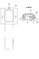
- FIG. 2 is a cross-sectional view taken along the line AA of the tapping device according to the present embodiment shown in FIG. 1B. It is a front view and a sectional view showing the state where a sheet and a mounting ring were attached to a tapping device concerning this embodiment.
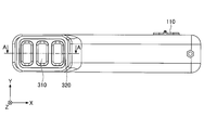
- FIG. 1A is a front view of the tapping device 1 according to the present embodiment.
- FIG. 1B is a side view of the tapping device 1 according to this embodiment.
- the longitudinal direction of the tapping device 1 (the lateral direction of FIGS. 1A and 1B) is the X axis
- the right direction is the X direction
- the left direction is the ⁇ X direction.
- the width direction of the tapping device 1 (vertical direction in FIG. 1B) is the Y axis
- the upward direction is the Y direction
- the downward direction is the ⁇ Y direction.
- the height direction of the tapping device 1 (vertical direction in FIG. 1A) is the Z axis, the upward direction is the Z direction, and the downward direction is the ⁇ Z direction.
- the tapping target is set to be parallel to the XY plane and tapped along the Z axis.
- the tapping device 1 includes a grip portion 100 and a tapping head portion 200.
- the grip portion 100 is a portion that the user holds with the hand when using the tapping device 1.
- the grip portion 100 of this embodiment includes a power switch 110. Further, an operation unit such as a setting switch other than the power switch 110 and a display unit showing the operating state may be provided.
- the grip part 100 of this embodiment incorporates a part of a control board 40, a battery 50, and a tapping mechanism part 400, which will be described later.
- the tapping head section 200 is a section that is pressed against a target such as the skin to be tapped by the user.
- the tapping head section 200 of this embodiment incorporates a part of a tapping mechanism section 400 described later.
- the tapping device 1 further includes a cover 300 on a portion to be pressed against an object to be tapped.
- FIG. 2 is an exploded perspective view of the tapping device 1 according to this embodiment.
- the tapping device 1 includes a housing 10.
- the housing 10 is configured by joining a top cover 11 and a bottom cover 12.
- the grip portion 100 is provided on the housing 10.
- a frame portion 15 is provided at the tip portion of the bottom cover 12.
- the frame portion 15 constitutes a part of the tapping head portion 200, and is provided so as to cover a side surface periphery of a finger portion 411 described later.
- the cover 300 is attached to the frame portion 15.
- the housing 10 includes a mechanical box 20 inside the housing 10.
- the mechanical box 20 is configured by connecting a mechanical box top cover 21 and a mechanical box bottom cover 22.
- the mechanical box 20 contains a part of the tapping mechanism section 400.
- a sound is generated when the tapping mechanism unit 400 operates. For example, sound is generated from the motor that is the driving unit 423 of the tapping mechanism unit 400.
- the tapping mechanism section 400 is doubly surrounded by the mechanical box 20 and the housing 10, so that sound is prevented from leaking to the outside of the housing 10. You can Therefore, it is possible to reduce the noise of the tapping device 1.
- the mechanical box 20 is installed in the housing 10 via the cushioning material 30.
- the tapping mechanism 400 generates vibration during operation. Vibration can be prevented from being transmitted to the housing 10 through the cushioning material 30. Furthermore, it is possible to prevent the sound of the tapping mechanism section 400 from being transmitted to the outside of the housing 10. Therefore, the noise of the tapping device 1 can be reduced by installing the mechanical box 20 of the present embodiment as described above.
- the housing 10 includes a control board 40 and a battery 50 in a top cover 11 and a bottom cover 12.
- the control board 40 includes a circuit for driving and controlling the driving unit 423 of the tapping mechanism unit 400.
- the battery 50 supplies electric power for driving the driving unit 423 of the tapping mechanism unit 400 and the control board 40, respectively.
- the tapping mechanism unit 400 causes the tapping device 1 to perform a tapping operation.
- FIG. 3 is a perspective view of the tapping mechanism unit 400 of the tapping device 1 according to this embodiment.
- FIG. 4 is a perspective view of the slider 410 of the tapping device 1 according to this embodiment.
- the tapping mechanism section 400 includes a slider 410, a driving member 420, and a pressing member 430.
- the slider 410 includes a finger portion 411 and a connecting member 412.
- the tapping device 1 of the present embodiment includes three sliders 410.
- the three sliders 410 are laterally arranged linearly. By arranging in a straight line, tapping can be performed with a human finger.
- the finger portion 411 is a member that taps the skin via the cover 300 when tapping.
- the shape of the finger portion 411 is a shape imitating the shape of a human finger. Specifically, it has a substantially rectangular shape when viewed from the front. It is preferable that a part of the cross section of the finger portion 411 is a part of a substantially ellipse simulating the shape of the belly part of the finger.
- the finger portion 411 is formed by one member, but it may be formed by using a plurality of members. For example, a rectangular parallelepiped and a rounded member may be combined and formed.
- the finger portion 411 may be removable from the connecting member 412. By making it removable, the user can select the finger portion 411 having a desired shape or the finger portion 411 having a preferable shape for the operation.
- the connecting member 412 is a member that connects the finger portion 411 and a cam receiving portion 421 described later at a predetermined interval.
- the driving member 420 includes a cam receiving portion 421, a cam shaft 422, and a driving portion 423.
- the cam receiving portion 421 is a member that engages with a cam 425 described later.
- One cam receiving portion 421 is provided for each slider 410.
- the tapping device 1 of this embodiment includes a total of three cam receiving portions 421.
- the cam receiving portion 421 is attached to the side of the connecting member 412 opposite to the finger portion 411.
- the cam shaft 422 is a member that rotates the cam 425.
- the cam shaft 422 includes the same number of cams 425 as the sliders 410.
- the cam shaft 422 is rotated by the drive unit 423.
- the cam 425 provided on the cam shaft 422 rotates.
- the rotating cam 425 engages with the cam receiving portion 421 to move the cam receiving portion 421 in the Z direction (first direction).
- the drive unit 423 is a member that rotates the cam shaft 422. In the present embodiment of FIG. 3, it is specifically a motor.
- a speed reducer may be provided between the drive unit 423 and the cam shaft 422.
- the rotation speed of the drive unit 423 or the cam shaft 422 may be adjustable. For example, by increasing the rotation speed, tapping can be performed with a fast rhythm, and by decreasing the rotation speed, tapping can be performed with a slow rhythm.
- the pressing member 430 is a member that presses the slider 410 in the ⁇ Z direction (second direction), which is the opposite direction to the Z direction (first direction).
- a compression spring provided between the slider 410 and the mechanical box top cover 21 is used as the pressing member 430.
- the maximum force of pressing the slider 410 of the compression spring of the present embodiment that is, the force (maximum load) of the compression spring when the compression spring is most compressed when the tapping device 1 is operated is 1 to 10N. Is desirable. Further, it is desirable to set it to 3 to 4N. By using such a force that presses the slider 410, tapping strength that reproduces tapping with a human finger is obtained.
- the pressing member 430 may be any member that can press the slider 410, and may be, for example, an elastic member such as a spring or rubber.
- an elastic member such as a spring or rubber.
- the pressing member 430 is a compression spring in the present embodiment, a tension spring may be used as the pressing member 430 to push the slider 410 by pulling it from the lower side.
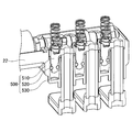
- FIG. 5 is a cross-sectional perspective view of the damper 500 of the tapping device 1 according to this embodiment.
- the damper 500 is a member that attenuates the speed when the slider 410 moves in the ⁇ Z direction (second direction), which is the opposite direction to the Z direction (first direction).
- the tapping device 1 of the present embodiment includes one damper 500 for each slider 410.
- the damper 500 includes a piston 510, an O ring 520, and a cylinder 530.
- the piston 510 of this embodiment is integrated with the cam receiving portion 421.
- the piston 510 has a substantially rod shape.
- a groove having a semicircular cross section is formed on the outer peripheral surface of the piston 510 at the outer periphery on the tip side. About half of the cross section of the O-ring 520 is fitted and mounted in the groove.
- the shape of the cylinder 530 of this embodiment is a substantially cylindrical shape having a bottom.
- the cylinder 530 of this embodiment is formed on the mechanical box bottom cover 22.
- the piston 510 is inserted into the cylinder 530.
- the O-ring 520 comes into close contact with the groove having a semicircular cross section of the piston 510 and the inner surface of the cylinder 530.
- the space surrounded by the piston 510, the O-ring 520, and the cylinder 530 is in a sealed state.
- the damper 500 operates as an air damper.
- a relatively loud impact sound is generated when the slider 410 is stopped at a high speed.
- the damper 500 By providing the damper 500, the speed of the slider 410 can be stopped while the speed is appropriately damped. Thereby, the impact sound can be reduced. Therefore, it is possible to reduce the noise of the tapping device 1.
- the air damper is used as the damper 500 of the present embodiment, a damper other than the air damper may be used.
- a damper other than the air damper may be used.
- a hydraulic type may be used.
- an elastic member such as rubber or spring may be used.
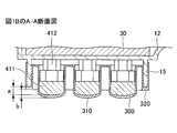
- FIG. 6 is a cross-sectional view of the tapping device 1 according to this embodiment.
- FIG. 6 is a sectional view taken along line AA of FIG. 1B. Note that FIG. 6 shows a cross section near the tapping head unit 200.
- FIG. 6 shows a state in which all the sliders 410 are stationary (stationary state) and the finger portions 411 are at the lowest point.
- the tapping device 1 of the present embodiment includes three sliders 410.
- Each slider 410 includes finger portions 411.
- the cover 300 is attached so as to cover the plurality of finger portions 411.
- the cover 300 includes a plurality of convex portions 310 corresponding to the finger portions 411, and a cover frame portion 320 surrounding the convex portions 310 and covering the frame portion 15.
- the cover 300 is attached by fitting the cover frame portion 320 of the cover 300 and the frame portion 15 of the bottom cover 12 together.
- the finger portion 411 is inserted from the side opposite to the tapping target side of the convex portion 310.
- the slider 410 is in a state in which the slider 410 is stationary without moving in the Z direction when the cam receiving portion 421 of the drive member 420 and the cam 425 are not engaged (stationary). State).
- the finger portion 411 projects from the frame portion 15 toward the tapping target side by a distance a as shown in FIG.
- the distance a is about 3 mm.
- the finger portion 411 projects from the frame portion 15 toward the tapping target side, whereas the convex portion 310 projects from the cover frame portion 320 toward the tapping target side by a distance b.
- the distance b is about 3 mm, which is the same as the distance a.
- the distance a and the distance b may be the same distance or different distances.
- the combined thickness of the epidermis and dermis of human skin is about 2.2 mm.
- the convex portion 310 can be pushed in by about 3 mm with the cover surface of the cover frame portion 320 in contact with the skin during driving.
- the protrusion 310 can be pushed into the dermis layer including the capillaries and lymphatic vessels by protruding the protrusion 310 by about 3 mm.
- the tapping device 1 of the present embodiment includes the frame portion 15 and the cover frame portion 320, by driving the finger portions 411 so that the cover frame portion 320 is brought into contact with the skin, the skin and the finger portions 411 are in use. The distance between and can be easily adjusted. Further, since the frame portion 15 and the cover frame portion 320 are provided, it is possible to prevent the finger portion 411 from being excessively pressed against the skin when the cover frame portion 320 contacts the skin.
- the cover 300 is preferably a liquid impermeable cover, that is, a liquid impermeable cover.
- the material of the cover 300 is preferably flexible because it comes into contact with the skin.
- the material of the cover 300 is rubber or elastomer. In particular, urethane and silicone are preferable. By using the flexible cover 300, it is possible to approximate the human skin sensation when touching.
- the cover 300 of the tapping device 1 of this embodiment covers a plurality of finger portions 411 with one cover 300.
- the number of parts can be reduced as compared with the case where each finger portion 411 is covered with an individual cover.
- by covering the spaces between the finger portions 411 with a cover it is possible to improve water resistance and prevent objects from being caught in the gaps between the finger portions 411.
- the cover 300 of the tapping device 1 is detachable because it is attached by fitting the cover frame portion 320 into the frame portion 15. Since the cover 300 is removable, for example, the user can change the cover 300 or use the cover 300 having different specifications such as thickness. Also, since it is removable, the cover 300 can be removed and washed when it becomes dirty.
- the surface of the cover 300 of the present embodiment is a smooth surface (curved surface), but is not limited thereto.
- protrusions may be provided on the surface.
- the surface of the cover 300 may be changed according to the purpose of tapping.
- the cover 300 having a smooth surface may be used for daily skin care, and the cover 300 having protrusions may be used for massage.
- FIG. 7 is a front view showing a state in which the seat 700 of the tapping device 1 and the mounting ring 600 are mounted.
- a cosmetic base such as a lotion using a nonwoven fabric
- tapping can be performed while using the sheet 700 containing the cosmetic base together.
- the sheet 700 is mounted on the cover 300 of the tapping device 1 by the mounting ring 600.
- the sheet 700 When performing tapping, it is preferable to impregnate the sheet 700 with a cosmetic base.
- the cosmetic base may be applied to the surface of the sheet 700.
- the sheet 700 may be any one that can be impregnated or coated with a cosmetic base.
- a sheet having a three-dimensional porous structure, particularly a non-woven fabric, a sponge, or a cloth is preferable.
- a nonwoven fabric containing cotton is preferable.
- the cosmetic base applied at the same time as the tapping device 1 of the present embodiment preferably contains a water-soluble active ingredient.
- the water-soluble active ingredient is preferably a moisturizing ingredient or a whitening ingredient.
- the moisturizing component preferably contains glycerin.
- the whitening component preferably contains any one of tranexamic acid, a vitamin C derivative, arbutin, 4-methoxysalicylic acid potassium salt, and nicotinic acid amide.
- the sheet 700 is attached to the tapping device 1 of this embodiment, it is not necessary to press the sheet 700 by hand. Therefore, tapping can be performed while applying the cosmetic base to the skin by operating the tapping device 1 with one hand.
- tapping device 1 of the present embodiment taps with the plurality of sliders 410, tapping such as finger tapping of an esthetician can be performed at the same time as putting with a nonwoven fabric. As a result, a higher beauty effect and a comfort that cannot be felt by one's hands can be realized.
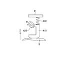
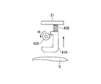
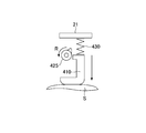
- 8A, 8B, and 8C are diagrams for explaining the tapping operation of the slider 410 of the tapping device 1 according to this embodiment.
- the camshaft 422 is rotated by the drive unit 423. As the cam shaft 422 rotates, the cam 425 rotates. In FIG. 8, the cam 425 rotates counterclockwise (in the direction of arrow R).
- FIG. 8A is a diagram showing a state before the cam 425 and the cam receiving portion 421 are engaged with each other. Since the slider 410 is pressed by the pressing member 430 in the ⁇ Z direction (second direction) that is the opposite direction to the Z direction (first direction), the finger portion 411 is at the lowest point. is there. Then, the skin S, which is the object of tapping, is in contact with the skin 300 via the cover 300. The cover 300 and the sheet 700 are omitted in FIGS. 8A, 8B, and 8C.
- FIG. 8B is a diagram showing a state in which the cam 425 and the cam receiving portion 421 are engaged with each other.
- the cam 425 and the cam receiving portion 421 are engaged with each other.
- the slider 410 moves in the Z direction (first direction) as the cam 425 rotates.
- the spring which is the pressing member 430, is compressed and elastic energy is accumulated.
- FIG. 8C is a diagram of a state immediately after the engagement between the cam 425 and the cam receiving portion 421 is disengaged.
- the cam 425 rotates while the cam 425 and the cam receiving portion 421 are engaged with each other, the engagement is disengaged.
- the slider 410 releases the accumulated elastic energy of the spring, which is the pressing member 430, so that the slider 410 is in the opposite direction to the Z direction (first direction), ie, ⁇ Z direction (second direction). ) To move linearly. Then, it moves and the finger portion 411 collides with the skin S that is the tapping target to perform tapping.
- the tapping device 1 of this embodiment can perform tapping without damaging the joint between the epidermis and the dermis, which causes sagging or spots during tapping.
- tapping is performed by the repulsive force of the spring which is the pressing member 430. Therefore, the skin can be tapped with almost constant strength. Further, even if the rotation speed of the driving unit 423 is changed, the strength of tapping does not change, and tapping can be performed with a constant strength.
- the slider when the slider is forcibly moved like a cam mechanism or a crank mechanism that uses a plate cam and a contactor, if a force is applied to the slider in the direction opposite to the movement direction, the operation stops. Or, in some cases, it may break down. Further, the slider is strongly pressed against the skin in proportion to the force of pressing the slider against the skin.
- the tapping mechanism unit 400 of the present embodiment even if the cover 300 is pressed against the skin and the slider 410 is pressed in the Z direction, the tapping mechanism unit 400 can move in the Z direction against the force of the pressing member 430. Therefore, even when the cover 300 is pressed against the skin, the tapping mechanism unit 400 can be prevented from malfunctioning.
- the tapping device 1 of this embodiment includes three sliders 410.
- tapping is sequentially performed in the order in which the sliders 410 close to the drive unit 423 are lined up.
- tapping can be performed so as to simulate a person tapping with fingers in order.
- a constant pressure stimulus with continuity can be applied to the skin.
- tapping may be sequentially performed from the slider 410 farther from the driving unit 423 in order.
- the sliders 410 may be individually tapped at different timings. Further, all the sliders 410 may be tapped at the same time.
- the number of the protrusions that engage with the cam receiving portion 421 of the cam 426 is one, but the number of the protrusions is not limited to one.
- two protrusions may be provided like the cam 426 of FIG. 9, or three or more protrusions may be provided.
- it is preferable that the number of rotations of the drive unit 423 or the cam shaft 422 and the number of protrusions of the cam 425 described above are determined so as to have a rhythm that reproduces human tapping.
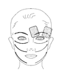
- FIG. 10 is a diagram illustrating a method of using the tapping device 1 according to this embodiment.
- a cosmetic base is included in the sheet 700 (for example, a nonwoven fabric made of cotton).
- the sheet 700 is attached to the tapping device 1.
- the tapping head portion 200 of the tapping device 1 is brought into close contact with the central portion of the face.
- the tapping device 1 is slowly slid laterally outward from the center of the face.
- (6) Repeat (5) several times while changing the place.
- tapping can be performed using the tapping device 1 of this embodiment.
- the tapping mechanism section 400 is housed inside the housing 10 and the cover 300. Therefore, the operating part of the tapping mechanism part 400 is not exposed to the outside and does not come into contact with it, so that it can be used safely.
- the tapping device 1 of the present embodiment is used by bringing the cover 300 into close contact with the skin. Therefore, when the tapping device 1 is used, it is easy to perform the alignment without having to adjust the distance between the skin and the hitting piece as in the prior art. Therefore, tapping can be performed easily.
- the cover 300 of the present embodiment is a liquid impermeable cover. Therefore, even if the liquid from the outside, in particular, the sheet 700 is used by being impregnated with the liquid cosmetic base, the cosmetic base does not enter the inside of the housing. Further, it is possible to prevent a failure due to the liquid entering the tapping device 1.
- the tapping device 1 of the present embodiment can perform the tapping by mounting the sheet 700 including the cosmetic base, the tapping using the cosmetic base can be easily performed.
- the tapping device 1 of this embodiment includes three sliders 410, but the number is not limited to three. Two or more may be used. For example, the number of sliders 410 may be four. Further, the number of sliders 410 may be one.
- the plurality of sliders 410 are linearly arranged, but the arrangement of the sliders is not limited to linear arrangement. For example, it may be curved. Further, the tapping device 1 of the present embodiment has one row, but two or more rows may be arranged.
- the maximum force for pressing the slider 410 of the pressing member 430 may be adjusted. For example, when the slider 410 is in a stationary state, the size of the spring that is the pressing member 430 may be changed and adjusted.
Landscapes
- Health & Medical Sciences (AREA)
- Epidemiology (AREA)
- Pain & Pain Management (AREA)
- Physical Education & Sports Medicine (AREA)
- Rehabilitation Therapy (AREA)
- Life Sciences & Earth Sciences (AREA)
- Animal Behavior & Ethology (AREA)
- General Health & Medical Sciences (AREA)
- Public Health (AREA)
- Veterinary Medicine (AREA)
- Percussion Or Vibration Massage (AREA)
Abstract
フィンガー部を備える複数の摺動子と、前記摺動子を第1の方向に移動させる駆動部材と、前記第1の方向とは逆の方向である第2の方向に前記摺動子を押圧する押圧部材と、を備えるタッピングデバイスであって、当該複数の摺動子の複数の前記フィンガー部を覆うカバーを更に備えるタッピングデバイス。
Description
本発明は、タッピングデバイスに関する。
従来から、コットン製等の不織布に化粧水を含ませてパッティング(肌を連続に軽くたたく行為)することが知られている。この不織布を用いることによって、角層への化粧水の浸透量を増やすことができる。
また、従来、人の皮膚を軽くたたく(タッピングする)機器が知られている。特許文献1には、指頭程度の大きさの叩打子により顔面皮膚を軽く且つリズミカルに叩打(タッピング)するタッピング式美容器が開示されている。
不織布に化粧水を含ませてパッティング(肌を連続でたたく行為)する際には、例えば、不織布の中心を中指の腹に置いて、中指と人差し指及び薬指とで不織布の端部を挟み込んで、肌をたたくようにする。しかしながら、不織布を適切に持ちながら、肌をたたくようにするには慣れが必要であり困難である。また、中指の腹で肌をたたくような単純なパッティングしかできない。例えば、不織布を手に持ちながら、エステで行われるような複数の指でタッピングするようなことはできない。
先行技術は、タッピング部材の叩打子が取付部を中心に回転する。タッピング部材の大部分が装置の框体から露出し、タッピング部材が可動する領域が広いことから、叩打(タッピング)する対象以外にタッピング部材が接触する可能性がある。また、先行技術では叩打子が適切な強度で肌を叩打するように手で装置を持ちながら肌と叩打子との間隔を調整しなければならず、間隔を一定に保ちつつ叩打子を肌に適切に当てるようにすることは困難である。
本発明の一実施形態は、タッピングを行う部材がタッピング対象以外に接触することなしに、肌に密着させて安全で簡単にタッピングを行うことができるタッピングデバイスを提供することを目的とする。
開示のタッピングデバイスは、フィンガー部を備える複数の摺動子と、前記摺動子を第1の方向に移動させる駆動部材と、前記第1の方向とは逆の方向である第2の方向に前記摺動子を押圧する押圧部材と、を備えるタッピングデバイスであって、当該複数の摺動子の複数の前記フィンガー部を覆うカバーを更に備える。
タッピングデバイスを肌に密着させて、タッピングを行う部材がタッピング対象以外に接触することなしに安全で簡単にタッピングを行うことができる。
以下に図面を参照して本実施形態について説明する。
最初に、タッピングデバイス1の外観について説明する。
図1Aは、本実施形態に係るタッピングデバイス1の正面図である。図1Bは、本実施形態に係るタッピングデバイス1の側面図である。最初に、方向について説明する。図1に座標軸を示す。図1Aの側面図及び図1Bの正面図において、タッピングデバイス1の長手方向(図1A,図1Bの左右方向)をX軸として、右方向をX方向、左方向を-X方向とする。図1Bの正面図において、タッピングデバイス1の幅方向(図1Bの上下方向)をY軸として、上方向をY方向、下方向を-Y方向とする。図1Aの側面図において、タッピングデバイス1の高さ方向(図1Aの上下方向)をZ軸として、上方向をZ方向、下方向を-Z方向とする。タッピング対象は、X-Y平面に平行になるようにして、Z軸に沿ってタッピングする。
タッピングデバイス1は、把持部100と、タッピングヘッド部200と、を備える。
把持部100は、使用者がタッピングデバイス1を使用する際に手で握る部分である。本実施形態の把持部100には、電源スイッチ110を備える。また、電源スイッチ110以外の設定スイッチ等の操作部や動作状態を示す表示部を備えてもよい。本実施形態の把持部100は、後述する制御基板40や電池50、タッピング機構部400の一部を内蔵する。
タッピングヘッド部200は、使用者がタッピングする肌等の対象に押し当てて使用する部分である。本実施形態のタッピングヘッド部200は、後述するタッピング機構部400の一部を内蔵する。
本実施形態に係るタッピングデバイス1は、タッピングする対象に押し当てる部分に、カバー300を更に備える。
次に、タッピングデバイス1の構成について説明する。
図2は、本実施形態に係るタッピングデバイス1の分解斜視図である。
タッピングデバイス1は、筐体10を備える。筐体10は、トップカバー11とボトムカバー12を結合することにより構成する。把持部100は、筐体10に設けられている。ボトムカバー12の先端部分には、枠部15を備える。枠部15は、タッピングヘッド部200の一部を構成し、後述するフィンガー部411の側面周囲を覆うように設けられる。枠部15には、カバー300が取り付けられる。
筐体10は、筐体10の内部にメカボックス20を備える。メカボックス20は、メカボックストップカバー21とメカボックスボトムカバー22を結合することにより構成する。メカボックス20は、タッピング機構部400の一部を内蔵している。タッピング機構部400において動作の際に音が発生する。例えば、タッピング機構部400の駆動部423であるモータから音が発生する。メカボックス20にタッピング機構部400を内蔵することによって、タッピング機構部400は、メカボックス20と筐体10とにより二重に囲まれるので、筐体10の外に音が漏れるのを防止することができる。したがって、タッピングデバイス1の低騒音化を行うことができる。
また、メカボックス20は、緩衝材30を介して筐体10に設置される。タッピング機構部400は動作の際に振動が発生する。緩衝材30を介することによって筐体10に振動が伝わることを防止することができる。さらに、タッピング機構部400の音が筐体10の外に伝わることを防止することができる。したがって、本実施形態のメカボックス20の上記のように設置することによって、タッピングデバイス1の低騒音化を行うことができる。
筐体10は、トップカバー11とボトムカバー12の中に制御基板40と、電池50を備える。制御基板40は、タッピング機構部400の駆動部423を駆動制御する回路等を備える。電池50は、タッピング機構部400の駆動部423と制御基板40を駆動する電力をそれぞれに供給する。
次に、タッピングデバイス1のタッピング機構部400について説明する。タッピング機構部400により、タッピングデバイス1はタッピング動作を行う。
図3は、本実施形態に係るタッピングデバイス1のタッピング機構部400の斜視図である。図4は、本実施形態に係るタッピングデバイス1の摺動子410の斜視図である。
タッピング機構部400は、摺動子410と、駆動部材420と、押圧部材430と、を備える。
タッピング機構部400の各部材について説明する。
摺動子410は、フィンガー部411と、連結部材412と、を備える。本実施形態のタッピングデバイス1は、3個の摺動子410を備える。本実施形態のタッピングデバイス1では、3個の摺動子410を横に直線状に並べている。直線状に並べることによって、人の指でタッピングするようにすることができる。
フィンガー部411は、タッピングを行う際にカバー300を介して肌をタッピングする部材である。フィンガー部411の形状は、人の指の形状を模した形状となっている。具体的には、正面視略長方形状の形状になっている。フィンガー部411の断面の一部は、指の腹部の形状を模した略楕円の一部とするのが好ましい。なお、本実施形態においては、フィンガー部411は一つの部材で形成しているが、複数の部材を用いて形成してもよい。例えば、直方体と丸みを帯びた部材を組み合わせて形成してもよい。
なお、フィンガー部411は、連結部材412から取り外し可能としてもよい。取り外し可能にすることによって、使用者は好みの形状のフィンガー部411を選んだり、施術に好ましい形状のフィンガー部411を選んだりすることができる。
連結部材412は、フィンガー部411と後述するカム受部421を所定の間隔で連結する部材である。
次に、駆動部材420について説明する。駆動部材420は、カム受部421と、カムシャフト422と、駆動部423と、を備える。
カム受部421は、後述するカム425と係合する部材である。カム受部421は、各摺動子410にそれぞれ1個設けられる。本実施形態のタッピングデバイス1は、合計3個のカム受部421を備える。カム受部421は、連結部材412のフィンガー部411とは反対側に取り付けられる。
カムシャフト422は、カム425を回動する部材である。カムシャフト422は、摺動子410と同じ個数のカム425を備える。カムシャフト422は、駆動部423により回動する。それによって、カムシャフト422に設けられているカム425が回動する。回動するカム425は、カム受部421と係合してカム受部421をZ方向(第1の方向)に移動させる。
駆動部423は、カムシャフト422を回動する部材である。図3の本実施形態では、具体的にはモータである。駆動部423とカムシャフト422との間に減速機を備えるようにしてもよい。なお、駆動部423又はカムシャフト422の回転数を調整可能としてもよい。例えば、回転数を上げることにより速いリズムでタッピングさせたり、回転数を下げることにより、ゆったりしたリズムでタッピングさせたりすることができる。
次に、押圧部材430について説明する。
押圧部材430は、摺動子410をZ方向(第1の方向)とは逆の方向である-Z方向(第2の方向)に押圧する部材である。本実施形態では、押圧部材430として、摺動子410とメカボックストップカバー21の間に設けた圧縮ばねを用いる。本実施形態の圧縮ばねの摺動子410を押圧する最大の力、すなわち、タッピングデバイス1を動作させたときに圧縮ばねを最も圧縮した場合の圧縮ばねの力(最大荷重)は、1~10Nであること望ましい。さらには、3~4Nにすることが望ましい。そのような摺動子410を押圧する力にすることよって、人の指によるタッピングを再現するようなタッピングの強さとなる。
押圧部材430は、摺動子410を押圧することができる部材であればよく、例えば、ばね、ゴム等の弾性部材等であればよい。なお、ばねについて、本実施形態では押圧部材430は圧縮ばねを用いているが、押圧部材430として引張りばねを用いて摺動子410を下側から引っ張るようにして押圧してもよい。
次にダンパ500について説明する。
図5は、本実施形態に係るタッピングデバイス1のダンパ500の断面斜視図である。ダンパ500は、摺動子410がZ方向(第1の方向)と逆の方向である-Z方向(第2の方向)に移動する際に、速度を減衰させる部材である。
本実施形態のタッピングデバイス1は、各摺動子410に一つずつダンパ500を備える。ダンパ500は、ピストン510と、Oリング520と、シリンダ530を備える。
本実施形態のピストン510は、カム受部421と一体となっている。ピストン510の形状は略棒状である。ピストン510の先端側の外周には、断面が半円状の溝が外周面に形成されている。Oリング520の断面の約半分が当該溝に嵌挿され装着される。
本実施形態のシリンダ530の形状は、底を有する略円筒形である。本実施形態のシリンダ530はメカボックスボトムカバー22に形成されている。
ピストン510は、シリンダ530に挿入される。その際に、Oリング520は、ピストン510の断面が半円状の溝とシリンダ530の内面に密着する。それによって、ピストン510、Oリング520、シリンダ530で囲まれる空間は密封状態となる。タッピングを行う際にピストン510がシリンダ530に押し込まれると、シリンダ530内の空気が圧縮されることから、摺動子410の速度を減衰させることができる。そのようにして、ダンパ500はエアダンパとして動作する。
摺動子410を早い速度状態で停止させると比較的大きな打撃音が発生する。ダンパ500を設けることによって、摺動子410の速度を適切に減衰させた状態で停止させることができる。それにより打撃音を小さくすることができる。したがって、タッピングデバイス1の低騒音化を行うことができる。
なお、本実施形態のダンパ500として、エアダンパを採用したが、エアダンパ以外のダンパを採用してもよい。例えば、油圧式を用いてもよい。また、ゴムやバネ等の弾性部材を用いてもよい。
次に、カバー300について図1、2、6を用いて説明する。
図6は、本実施形態に係るタッピングデバイス1の断面図である。図6は、図1BのA-Aで切断した断面図である。なお、図6では、タッピングヘッド部200近辺の断面を示す。図6は、すべての摺動子410が静止した状態(静止状態)で、フィンガー部411が最下点にある状態を示す。
本実施形態のタッピングデバイス1は、3個の摺動子410を備える。各摺動子410は、フィンガー部411を備える。カバー300は、その複数のフィンガー部411を覆うように取り付けられている。
図6に示すように、カバー300は、フィンガー部411に対応する複数の凸部310と、凸部310を取り囲み、枠部15を覆うカバー枠部320を備える。カバー300は、カバー300のカバー枠部320とボトムカバー12の枠部15とをはめ合わせることで取り付ける。また、フィンガー部411は、凸部310のタッピング対象側とは反対側から挿入される。
ここで、本実施形態のタッピングデバイス1のフィンガー部411と枠部15との位置関係について説明する。摺動子410は、後述するように、駆動部材420のカム受部421とカム425が係合していない状態では、Z方向に移動されずに摺動子410が静止している状態(静止状態)となる。そのような静止状態において、フィンガー部411は枠部15より、図6に示すように距離aだけタッピング対象側に突出している。本実施形態のタッピングデバイス1では、距離aは約3mmである。
上記のように、フィンガー部411は枠部15よりタッピング対象側に突出しているのに対応して、凸部310は、カバー枠部320より距離bだけタッピング対象側に突出している。本実施形態のタッピングデバイス1では、距離bは距離aと同じく約3mmである。なお、距離aと距離bは同じ距離であってもよいし、異なる距離であってもよい。
人の皮膚の表皮と真皮をあわせた厚さは約2.2mm程度である。駆動時にカバー枠部320のカバー面を肌に当てた状態で、凸部310を約3mm押し込むことができる。その結果、凸部310を約3mm突出されることによって、毛細血管やリンパ管を含む真皮層まで凸部310押し込むことができる。真皮まで押し込むことによって体液の循環を効果的に促すことが可能となる。
本実施形態のタッピングデバイス1では、枠部15とカバー枠部320を備えているので、カバー枠部320を肌に当てるようにフィンガー部411を駆動することより使用状態において、肌とフィンガー部411との間隔の調整を簡単に行うことができる。また、枠部15とカバー枠部320を備えているので、カバー枠部320が肌に当たることによって、肌にフィンガー部411を強く抑え過ぎるのを防止することができる。
カバー300は、液体を透過しない、すなわち、液体非透過性のカバーが好ましい。カバー300の材質は、肌に接触することから柔軟性のあるものが望ましい。例えば、カバー300の材質は、ゴムやエラストマー等である。特に、ウレタンやシリコーンであることが好ましい。柔軟性のあるカバー300を用いることによって、接触したときに人の肌の感覚に近づけることができる。
本実施形態のタッピングデバイス1のカバー300は、複数のフィンガー部411を一つのカバー300で覆う。そのことによって、各フィンガー部411を個別のカバーで覆うのと比較して、部品点数を減らすことができる。また、フィンガー部411の間もカバーで覆うことによって、耐水性を向上させたり、フィンガー部411の隙間にものが挟まることを防止したりすることができる。
本実施形態のタッピングデバイス1のカバー300は、枠部15にカバー枠部320をはめ込むことで取り付けていることから取り外しが可能になっている。カバー300を取り外し可能であることによって、例えば、使用者によってカバー300を変えたり、厚み等の仕様の異なるカバー300を使用したりすることが可能である。また、取り外し可能であることから、カバー300を取り外して、汚れた際に洗うことができる。
また、本実施形態のカバー300の表面は、平滑な面(曲面)となっているがそれに限らない。例えば、突起を表面に備えるようにしてもよい。また、カバー300の表面をタッピングの用途に応じて変更してもよい。例えば、日常のスキンケアの際には、平滑な面のカバー300を用いて、マッサージの際には、突起を備えるカバー300を用いてもよい。
次に、タッピングデバイス1と併用するシート700とシート700を装着するための装着リング600について説明する。
図7は、タッピングデバイス1のシート700と装着リング600とを装着した状態を示す正面図である。従来技術で述べたように、不織布を用いて化粧水等の化粧基剤を適用すると角層への化粧水の浸透量が増える効果があることが知られている。本実施形態のタッピングデバイス1では、化粧基剤を含むシート700を併用しながらタッピングを行うことができる。シート700は、装着リング600によりタッピングデバイス1のカバー300の上に取り付ける。
タッピングを行う際は、化粧基剤をシート700に含浸されるのが好ましい。また、化粧基剤は、シート700のシート表面に塗工させているようにしてもよい。
シート700は、化粧基剤を含浸又は塗工できるものであればよい。例えば、3次元多孔質構造のシート、特に、不織布、スポンジ、布のいずれかであることが好ましい。特に、コットンを含む不織布が好ましい。
本実施形態のタッピングデバイス1と同時に適用する化粧基剤は、水溶性有効成分を配合していることが好ましい。さらに水溶性有効成分は、保湿成分又は美白成分であることが好ましい。保湿成分は、グリセリンを含むことが好ましい。美白成分は、トラネキサム酸、ビタミンC誘導体、アルブチン、4-メトキシサリチル酸カリウム塩、ニコチン酸アミドのいずれかを含むことが好ましい。
本実施形態のタッピングデバイス1にシート700を取り付けられているので、シート700を手で押さえる必要がない。したがって、片手でのタッピングデバイス1の操作で、肌に化粧基剤を適用しながらタッピングすることができる。
本実施形態のタッピングデバイス1は、複数の摺動子410によって、タッピングを行うことから、不織布によるパッティングと同時にエステティシャンのフィンガータッピングのようなタッピングを行うことができる。それによって、より高い美容効果と自分の手では感じることができない心地よさを実現することができる。
次にタッピング機構部400の動作について説明する。
図8A、図8B、図8Cは、本実施形態に係るタッピングデバイス1の摺動子410のタッピング動作を説明する図である。
カムシャフト422は駆動部423により回転する。カムシャフト422が回転することにより、カム425が回転する。図8において、カム425は反時計回り(矢印Rの方向)に回転する。
図8Aは、カム425とカム受部421が係合する前の状態の図である。摺動子410は、押圧部材430によってZ方向(第1の方向)と逆の方向である-Z方向(第2の方向)に押圧されていることから、フィンガー部411は、最下点にある。そして、タッピング対象である肌Sにカバー300を介して接している。なお、図8A、図8B、図8Cではカバー300とシート700は省略している。
図8Bは、カム425とカム受部421が係合している状態の図である。カム425が駆動されることにより、カム425とカム受部421が係合する。カム425とカム受部421が係合すると、カム425が回転するにしたがって、摺動子410がZ方向(第1の方向)に移動する。押圧部材430であるバネは圧縮されて弾性エネルギーが蓄積される。
図8Cは、カム425とカム受部421の係合が外れた直後の状態の図である。カム425とカム受部421が係合している状態で、カム425が回転していくと係合が外れる。係合が外れると、摺動子410は、押圧部材430であるバネの蓄積された弾性エネルギーが解放されてZ方向(第1の方向)と逆の方向である-Z方向(第2の方向)に直線的に移動する。そして、移動して、タッピング対象である肌Sにフィンガー部411が衝突してタッピングを行う。
ここで肌に加わる力の影響について説明する。例えば、ローラ等により肌に横方向に力が加わると表皮と真皮との接合部を破壊してたるみやシミの原因になる。従来技術も叩打子が取付け部を中心に回転することから、肌に垂直に叩打することは困難である。本実施形態のタッピングデバイス1の摺動子410は、直線的に移動する。そのことから、肌に横方向に力が加わることなく肌をタッピングする際に常に肌に垂直に力を加えることができる。したがって、本実施形態のタッピングデバイス1は、タッピングの際にたるみやシミの原因となる表皮と真皮との接合部を傷つけることなくタッピングすることができる。
本実施形態のタッピング機構部400では、カム425とカム受部421の係合が外れた後は、押圧部材430であるバネの反発力によってタッピングする。そのことから、ほぼ一定の強さで肌をタッピングすることができる。また、駆動部423の回転数を変えても、タッピングの強さは変わらず、一定の強さでタッピングを行うことができる。
また、例えば、板カムと接触子を用いるカム機構やクランク機構のように強制的に摺動子を移動させる場合には、摺動子に移動方向と逆方向に力がかかると、動作が止まったり、場合によっては故障したりする可能性がある。また、摺動子を肌に押し付ける力に比例して摺動子が肌に強く押し付けられることになる。
本実施形態のタッピング機構部400では、例えば、肌にカバー300を押し付けて摺動子410をZ方向に押しても、押圧部材430の力に抗してZ方向に移動することが可能である。したがって、肌にカバー300を押し付けた時にも、タッピング機構部400の故障を防止することできる。
図3に示すように、本実施形態のタッピングデバイス1は、3つの摺動子410を備える。本実施形態では、駆動部423に近い摺動子410から並んでいる順番に順次タッピングを行う。そのようにタッピングすることによって、人が指で順番にタッピングするのを模擬するようにタッピングすることができる。また、順番にタッピングすることによって、連続性のある一定の圧刺激を肌に与えることができる。
なお、タッピングする順番については、本実施形態の例に限らず例えば駆動部423から遠い摺動子410から順番に順次タッピングしてもよい。また、順番にタッピングするのではなく、各摺動子410がお互いにタイミングをずらして個別にタッピングするようにしてもよい。さらにすべての摺動子410が同時にタッピングしてもよい。
また、図8では、カム426のカム受部421と係合する突起は1つであったが、突起の数は1つに限らない。例えば、図9のカム426のように2つの突起を設けてもよいし、3つ以上の突起を設けてもよい。また、上述の駆動部423又はカムシャフト422の回転数とカム425の突起の数は、人のタッピングを再現するようなリズムとなるように決めることが好ましい。
次に、タッピングデバイス1の使用方法について説明する。
図10は、本実施形態に係るタッピングデバイス1の使用方法について説明する図である。
以下の手順に従ってタッピングデバイス1を使用する。
(1)化粧基剤をシート700(例えば、コットン製の不織布)に含ませる。
(2)タッピングデバイス1にシート700を装着する。
(3)タッピングデバイス1の電源を入れる。
(4)タッピングデバイス1のタッピングヘッド部200を顔の中心部分に密着させる。
(5)図10のように、顔の中心から外側に向かってゆっくりと横にタッピングデバイス1をスライドさせる。
(6)場所を変えながら(5)を数回繰り返す。
(7)タッピングデバイス1の電源を切る。
(2)タッピングデバイス1にシート700を装着する。
(3)タッピングデバイス1の電源を入れる。
(4)タッピングデバイス1のタッピングヘッド部200を顔の中心部分に密着させる。
(5)図10のように、顔の中心から外側に向かってゆっくりと横にタッピングデバイス1をスライドさせる。
(6)場所を変えながら(5)を数回繰り返す。
(7)タッピングデバイス1の電源を切る。
このように本実施形態のタッピングデバイス1を用いてタッピングを行うことができる。
次に、本実施形態のタッピングデバイス1の特徴についてまとめる。
本実施形態のタッピングデバイス1では、タッピング機構部400が筐体10とカバー300の内部に収納されている。そのことから、タッピング機構部400の稼働部分が外部に露出することなく、接触することがないので安全に使用することができる。
また、本実施形態のタッピングデバイス1は、カバー300を肌に密着させて使用する。そのことから、タッピングデバイス1を使用する際に、従来技術のように肌と叩打子との間隔を調整する必要がなく位置合わせをするのか容易である。したがって、簡単にタッピングを行うことができる。
さらに、本実施形態のカバー300は液体非透過性のカバーである。そのことから、外部からの液体、特に、シート700に液状の化粧基剤を含浸させて用いても化粧基剤が筐体内部に侵入することない。また、液体がタッピングデバイス1の内部に侵入することによる故障を防止することができる。
また、本実施形態のタッピングデバイス1は、化粧基剤を含むシート700を装着してタッピングを行うことができることから、化粧基剤を併用したタッピングを簡単に行うことができる。
なお、本実施形態のタッピングデバイス1は、3個の摺動子410を備えているが、個数については、3個に限らない。2個以上であればよい。例えば、摺動子410を4個としてもよい。また、摺動子410が1個であってもよい。
また、本実施形態のタッピングデバイス1は、複数の摺動子410を直線状に並べているが、摺動子の配置は直線状に並べるのに限らない。例えば、曲線状にならべてもよい。また、本実施形態のタッピングデバイス1は1列であるが、2列以上並べてもよい。
さらに、押圧部材430の摺動子410を押圧する最大の力を調整できるようにしてもよい。例えば、摺動子410の静止状態において、押圧部材430であるばねの寸法を変えるようにして調整するようにしてもよい。
以上、本発明を実施例に基づいて説明したが、本発明は上記実施例に限定されるものではなく、特許請求の範囲に記載の範囲内で様々な変形が可能である。
本願は、日本特許庁に2018年11月19日に出願された基礎出願特願2018-216534号の優先権を主張するものであり、その全内容を参照によりここに援用する。
1 タッピングデバイス
15 枠部
300 カバー
320 カバー枠部
410 摺動子
411 フィンガー部
420 駆動部材
421 カム受部
422 カムシャフト
425 カム
430 押圧部材
500 ダンパ
600 装着リング
700 シート
15 枠部
300 カバー
320 カバー枠部
410 摺動子
411 フィンガー部
420 駆動部材
421 カム受部
422 カムシャフト
425 カム
430 押圧部材
500 ダンパ
600 装着リング
700 シート
Claims (19)
- フィンガー部を備える複数の摺動子と、前記摺動子を第1の方向に移動させる駆動部材と、前記第1の方向とは逆の方向である第2の方向に前記摺動子を押圧する押圧部材と、を備えるタッピングデバイスであって、
当該複数の摺動子の複数の前記フィンガー部を覆うカバーを更に備えること
を特徴するタッピングデバイス。 - 前記カバーは液体非透過性であること
を特徴とする請求項1に記載のタッピングデバイス。 - 当該複数の摺動子はダンパを備えること
を特徴とする請求項1又は請求項2のいずれかに記載のタッピングデバイス。 - 前記ダンパはエアダンパであること
を特徴とする請求項3に記載のタッピングデバイス。 - 前記カバーを覆うシート及び前記シートを取り付ける装着リングを備えること
を特徴とする請求項1~4のいずれか一項に記載のタッピングデバイス。 - 前記シートは、化粧基剤を含むこと
を特徴とする請求項5に記載のタッピングデバイス。 - 前記化粧基剤は、前記シートに含浸されている、又は、前記シートの表面に塗工されていること
を特徴とする請求項6に記載のタッピングデバイス。 - 前記化粧基剤は、水溶性有効成分を配合していること
を特徴とする請求項6又は請求項7のいずれかに記載のタッピングデバイス。 - 前記水溶性有効成分が、保湿成分又は美白成分であること
を特徴とする請求項8に記載のタッピングデバイス。 - 前記保湿成分は、グリセリンを含むこと
を特徴とする請求項9に記載のタッピングデバイス。 - 前記美白成分は、トラネキサム酸、ビタミンC誘導体、アルブチン、4-メトキシサリチル酸カリウム塩、ニコチン酸アミドのいずれかを含むこと
を特徴とする請求項9に記載のタッピングデバイス。 - 前記シートは、3次元多孔質構造のシートであること
を特徴とする請求項5~11のいずれか一項に記載のタッピングデバイス。 - 前記フィンガー部の断面の一部は、指の腹部の形状を模した略楕円の一部であること
を特徴とする請求項1~12のいずれか一項に記載のタッピングデバイス。 - 前記押圧部材の前記摺動子を押圧する最大の力が1~10Nであること
を特徴とする請求項1~13のいずれか一項に記載のタッピングデバイス。 - 前記フィンガー部の側面周囲を覆う枠部を備え、
前記カバーは、前記フィンガー部を覆う凸部と、前記枠部を覆うカバー枠部と、を備え、
前記凸部が前記カバー枠部より、静止状態でタッピング対象側に突出すること
を特徴とする請求項1~14のいずれか一項に記載のタッピングデバイス。 - 前記凸部が前記カバー枠部より、静止状態でタッピング対象側に2~5mm突出すること
を特徴とする請求項15のいずれか一項に記載のタッピングデバイス。 - 前記複数の摺動子は、前記摺動子が並んでいる順番に順次タッピングすること
を特徴とする請求項1~16のいずれか一項に記載のタッピングデバイス。 - 前記複数の摺動子は、お互いにタイミングをずらして個別にタッピングすること
を特徴とする請求項1~16のいずれか一項に記載のタッピングデバイス。 - 前記駆動部材は、前記複数の摺動子に設けられた複数のカム受部と、当該複数のカム受部に係合する複数のカムと、前記複数のカムを駆動するカムシャフトを含み、
前記カムが駆動されることにより、前記カムと前記カム受部が係合して前記摺動子が前記第1の方向に移動し、
前記カムと前記カム受部との係合が外れて、前記摺動子の前記フィンガー部が前記押圧部材の押圧する方向に直線的に移動し、
前記摺動子の前記フィンガー部が前記押圧部材の押圧する方向に移動することによって、前記フィンガー部がタッピングすること
を特徴とする請求項1~18のいずれか一項に記載のタッピングデバイス。
Priority Applications (2)
| Application Number | Priority Date | Filing Date | Title |
|---|---|---|---|
| CN201980075655.6A CN113056252A (zh) | 2018-11-19 | 2019-11-18 | 叩打装置 |
| JP2020558388A JP7697786B2 (ja) | 2018-11-19 | 2019-11-18 | タッピングデバイス |
Applications Claiming Priority (2)
| Application Number | Priority Date | Filing Date | Title |
|---|---|---|---|
| JP2018216534 | 2018-11-19 | ||
| JP2018-216534 | 2018-11-19 |
Publications (1)
| Publication Number | Publication Date |
|---|---|
| WO2020105593A1 true WO2020105593A1 (ja) | 2020-05-28 |
Family
ID=70773687
Family Applications (1)
| Application Number | Title | Priority Date | Filing Date |
|---|---|---|---|
| PCT/JP2019/045122 Ceased WO2020105593A1 (ja) | 2018-11-19 | 2019-11-18 | タッピングデバイス |
Country Status (3)
| Country | Link |
|---|---|
| JP (1) | JP7697786B2 (ja) |
| CN (1) | CN113056252A (ja) |
| WO (1) | WO2020105593A1 (ja) |
Citations (5)
| Publication number | Priority date | Publication date | Assignee | Title |
|---|---|---|---|---|
| JPS5345084A (en) * | 1976-10-04 | 1978-04-22 | Souji Kawada | Entire body stimulating device |
| JPH0595530U (ja) * | 1992-06-08 | 1993-12-27 | 株式会社ニチエイ | 美顔器 |
| JP2007029518A (ja) * | 2005-07-28 | 2007-02-08 | Chiken Kk | トリートメント装置 |
| JP2012061251A (ja) * | 2010-09-17 | 2012-03-29 | Kyushu Hitachi Maxell Ltd | 美容器具 |
| JP2014061190A (ja) * | 2012-09-21 | 2014-04-10 | Family Inada Co Ltd | 手持ち型マッサージ機 |
Family Cites Families (14)
| Publication number | Priority date | Publication date | Assignee | Title |
|---|---|---|---|---|
| JP3949071B2 (ja) | 2003-03-11 | 2007-07-25 | 株式会社友泉 | 叩打振動マッサージ器 |
| CN202061048U (zh) * | 2010-12-24 | 2011-12-07 | 佛山市顺德区盛熙电器制造有限公司 | 一种手指按摩装置 |
| CN202620167U (zh) * | 2012-05-15 | 2012-12-26 | 广州腾龙电子塑胶科技有限公司 | 一种安装于水中的电磁按摩装置 |
| TWI461189B (zh) * | 2012-09-26 | 2014-11-21 | Joong Chenn Industry Co Ltd | Automatic tapping mechanism |
| JP2014108160A (ja) * | 2012-11-30 | 2014-06-12 | Panasonic Corp | 頭皮ケア装置 |
| CN103101284B (zh) * | 2013-02-17 | 2015-04-22 | 中国神华能源股份有限公司 | 滚筒胶板压实装置 |
| CN203724435U (zh) * | 2014-03-03 | 2014-07-23 | 南京友谊整形外科医院有限责任公司 | 一种面部皮肤除皱仪 |
| CN203953483U (zh) * | 2014-06-12 | 2014-11-26 | 宁波丹龙电器制造有限公司 | 一种洗脸刷 |
| CN205235165U (zh) * | 2015-12-10 | 2016-05-18 | 厦门宏湾医疗科技有限公司 | 超声波导入仪 |
| CN106208507B (zh) * | 2016-09-07 | 2017-06-16 | 东莞市长锦成电器有限公司 | 一种专用于足部按摩垫的电机 |
| CN207084967U (zh) * | 2017-01-18 | 2018-03-13 | 陶素芹 | 一种内分泌理疗护理装置 |
| CN108403410A (zh) * | 2017-09-14 | 2018-08-17 | 童振锴 | 一种中药熏蒸盆 |
| CN107811837A (zh) * | 2017-11-28 | 2018-03-20 | 盛珊瑜 | 一种医疗神经科用可转换按摩头的康复保健按摩器 |
| CN108186305A (zh) * | 2018-01-23 | 2018-06-22 | 长沙理工大学 | 手指按摩器 |
-
2019
- 2019-11-18 WO PCT/JP2019/045122 patent/WO2020105593A1/ja not_active Ceased
- 2019-11-18 JP JP2020558388A patent/JP7697786B2/ja active Active
- 2019-11-18 CN CN201980075655.6A patent/CN113056252A/zh active Pending
Patent Citations (5)
| Publication number | Priority date | Publication date | Assignee | Title |
|---|---|---|---|---|
| JPS5345084A (en) * | 1976-10-04 | 1978-04-22 | Souji Kawada | Entire body stimulating device |
| JPH0595530U (ja) * | 1992-06-08 | 1993-12-27 | 株式会社ニチエイ | 美顔器 |
| JP2007029518A (ja) * | 2005-07-28 | 2007-02-08 | Chiken Kk | トリートメント装置 |
| JP2012061251A (ja) * | 2010-09-17 | 2012-03-29 | Kyushu Hitachi Maxell Ltd | 美容器具 |
| JP2014061190A (ja) * | 2012-09-21 | 2014-04-10 | Family Inada Co Ltd | 手持ち型マッサージ機 |
Also Published As
| Publication number | Publication date |
|---|---|
| JPWO2020105593A1 (ja) | 2021-09-30 |
| JP7697786B2 (ja) | 2025-06-24 |
| CN113056252A (zh) | 2021-06-29 |
Similar Documents
| Publication | Publication Date | Title |
|---|---|---|
| JP5916362B2 (ja) | 美顔器 | |
| CN208877207U (zh) | 一种用于按摩仪的枢转装置和包括该枢转装置的按摩仪 | |
| US20140345643A1 (en) | Vibration Puff Having Elastic Moving Body Inside | |
| JP5832421B2 (ja) | 美肌装置 | |
| EP1481657A3 (en) | Massaging device | |
| JP2012501684A (ja) | スキンケアのためのマッサージ装置 | |
| US12245982B1 (en) | Length-adjustable meandering masseur | |
| JP2010075288A (ja) | 施療子及びそれを用いたマッサージ器 | |
| KR20220167754A (ko) | 손 마사지 장치 | |
| KR101248038B1 (ko) | 눈 마사지기 | |
| KR101779083B1 (ko) | 안마기의 손 지압 패드 | |
| JP7697786B2 (ja) | タッピングデバイス | |
| KR101530165B1 (ko) | 안면 마사지 장치 | |
| CN212065959U (zh) | 多头式自适应美容仪 | |
| JP7355349B1 (ja) | 頭皮マッサージ装置 | |
| JP3139689U (ja) | マッサージウェア構造 | |
| CN110090147B (zh) | 一种可点穴按摩头及按摩椅 | |
| CN2796700Y (zh) | 简易型按摩器 | |
| JPH11332955A (ja) | 健康器具 | |
| JP2014094262A (ja) | 頭皮マッサージ器 | |
| JP5463505B2 (ja) | ハンドマッサージロボット | |
| JP2014200373A (ja) | マッサージ機 | |
| JP2004313689A (ja) | スライド式指圧部を備えたマッサージ器 | |
| JP7455419B1 (ja) | 美容鍼ヘッド、および美容鍼ヘッドを備えるマッサージ機器 | |
| CN214596468U (zh) | 一种头部振动按摩器 |
Legal Events
| Date | Code | Title | Description |
|---|---|---|---|
| 121 | Ep: the epo has been informed by wipo that ep was designated in this application |
Ref document number: 19887832 Country of ref document: EP Kind code of ref document: A1 |
|
| ENP | Entry into the national phase |
Ref document number: 2020558388 Country of ref document: JP Kind code of ref document: A |
|
| NENP | Non-entry into the national phase |
Ref country code: DE |
|
| 122 | Ep: pct application non-entry in european phase |
Ref document number: 19887832 Country of ref document: EP Kind code of ref document: A1 |