WO2020105491A1 - 弾性ローラ - Google Patents
弾性ローラInfo
- Publication number
- WO2020105491A1 WO2020105491A1 PCT/JP2019/044128 JP2019044128W WO2020105491A1 WO 2020105491 A1 WO2020105491 A1 WO 2020105491A1 JP 2019044128 W JP2019044128 W JP 2019044128W WO 2020105491 A1 WO2020105491 A1 WO 2020105491A1
- Authority
- WO
- WIPO (PCT)
- Prior art keywords
- silicone oil
- elastic
- isocyanate compound
- surface layer
- elastic roller
- Prior art date
- Legal status (The legal status is an assumption and is not a legal conclusion. Google has not performed a legal analysis and makes no representation as to the accuracy of the status listed.)
- Ceased
Links
Images

Classifications
-
- F—MECHANICAL ENGINEERING; LIGHTING; HEATING; WEAPONS; BLASTING
- F16—ENGINEERING ELEMENTS AND UNITS; GENERAL MEASURES FOR PRODUCING AND MAINTAINING EFFECTIVE FUNCTIONING OF MACHINES OR INSTALLATIONS; THERMAL INSULATION IN GENERAL
- F16C—SHAFTS; FLEXIBLE SHAFTS; ELEMENTS OR CRANKSHAFT MECHANISMS; ROTARY BODIES OTHER THAN GEARING ELEMENTS; BEARINGS
- F16C13/00—Rolls, drums, discs, or the like; Bearings or mountings therefor
-
- G—PHYSICS
- G03—PHOTOGRAPHY; CINEMATOGRAPHY; ANALOGOUS TECHNIQUES USING WAVES OTHER THAN OPTICAL WAVES; ELECTROGRAPHY; HOLOGRAPHY
- G03G—ELECTROGRAPHY; ELECTROPHOTOGRAPHY; MAGNETOGRAPHY
- G03G15/00—Apparatus for electrographic processes using a charge pattern
-
- G—PHYSICS
- G03—PHOTOGRAPHY; CINEMATOGRAPHY; ANALOGOUS TECHNIQUES USING WAVES OTHER THAN OPTICAL WAVES; ELECTROGRAPHY; HOLOGRAPHY
- G03G—ELECTROGRAPHY; ELECTROPHOTOGRAPHY; MAGNETOGRAPHY
- G03G15/00—Apparatus for electrographic processes using a charge pattern
- G03G15/06—Apparatus for electrographic processes using a charge pattern for developing
- G03G15/08—Apparatus for electrographic processes using a charge pattern for developing using a solid developer, e.g. powder developer
Definitions
- the present invention relates to an elastic roller.
- Development rollers used in image forming devices such as copiers, printers, and facsimiles that use electrophotography have the function of conveying the developer to the image carrier on which the electrostatic latent image is formed.
- the developer transportability of the developing roller affects the quality of the image forming apparatus, especially the print density. Therefore, it has been studied to form unevenness on the surface of the developing roller and adjust the electrical characteristics of various materials forming the developing roller, thereby improving the developer transportability of the developing roller.
- the developer may stick to the surface of the developing roller when used for a long time (referred to as "filming").
- filming is, for example, because the developer is deformed or destroyed by the sliding stress of the blade or the like that is in pressure contact with the elastic roller when the developer is charged or adhered, and further, the development by frictional heat with the blade or the like is performed. It is considered to be caused by the melting of the agent.
- it has been required to provide an elastic roller in which the occurrence of filming is suppressed as much as possible and thereby the durable printing performance is stabilized.
- a liquid binder containing (A) a polyol, an isocyanate compound, and a reactive silicone oil, (B) silicone rubber particles, and (C) a diluting solvent are provided.
- An elastic roller is disclosed having a surface layer formed by applying and curing a mixture containing the same.
- the inventors of the present invention have shown that by coating and curing a mixture containing at least a binder main agent obtained by polymerizing a composition composed of a silicone oil modified at both ends and an isocyanate compound, and a blocked isocyanate compound.
- the inventors have found that an elastic roller having a surface layer has excellent suppression of filming generation and excellent productivity, and has completed the present invention.
- the present invention provides the following.
- An elastic roller which is obtained by applying and curing (A) A binder main agent obtained by polymerizing a composition containing a silicone oil modified at both ends and an isocyanate compound, (B) a blocked isocyanate compound, (C) a silicone rubber particle and / or acrylic having a particle diameter of 0.2 ⁇ m or more and 10 ⁇ m or less. Particles, (D) diluent solvent.
- component (A) is a binder main agent obtained by polymerizing a composition containing both-end modified silicone oil, one-end diol modified silicone oil, and an isocyanate compound.
- the component (A) is a binder main agent obtained by polymerizing a composition containing a silicone oil modified at both ends, a silicone oil modified at one end with a diol, an isocyanate compound, and a carbonate polyol and / or a hydrogenated butadiene polyol. )
- the elastic roller described in (1) is a binder main agent obtained by polymerizing a composition containing a silicone oil modified at both ends, a silicone oil modified at one end with a diol, an isocyanate compound, and a carbonate polyol and / or a hydrogenated butadiene polyol.
- the component (B) is an isocyanurate type blocked isocyanate end-capped with methyl ethyl ketone oxime or an adduct type blocked isocyanate end-capped with methyl ethyl ketone oxime.
- the elastic roller of the present invention coats and cures a mixture containing at least a binder main agent obtained by polymerizing a composition consisting of silicone oil modified at both ends and an isocyanate compound, and a blocked isocyanate compound. Therefore, the reaction between the isocyanate compound and the binder main agent having a hydroxyl group after the preparation of the mixture can be easily controlled, so that the viscosity of the mixture is not improved and the workability is excellent. Furthermore, since the surface layer of the elastic roller formed from this mixture has a low relative dielectric constant, the occurrence of filming is well suppressed even after long-term use.
- the elastic roller 1 of the present invention includes a shaft body 2, an elastic layer 3 provided on the outer surface of the shaft body 2, and a surface layer 4 provided outside the elastic layer 3.
- the elastic roller 1 of the present invention is preferably used as a developing roller, but is not limited to such an application.
- shaft body 2 As the shaft body 2, preferably, a shaft body having a conductive property and used in a conventionally known elastic roller can be used.
- the shaft body 2 is preferably made of at least one metal selected from the group consisting of iron, aluminum, stainless steel, and brass, for example.
- such a shaft body 2 is generally known by the name of "core bar”.
- the shaft body 2 may include an insulating resin.
- the insulating resin may be, for example, a thermoplastic resin or a thermosetting resin.
- the shaft body 2 may include, for example, a core body made of an insulating resin and a plating layer provided on the core body. Such a shaft body 2 can be obtained, for example, by plating a core body made of an insulating resin to make it conductive.
- the shaft body 2 is preferably a core metal in order to obtain good conductive properties.
- the shape of the shaft body 2 is preferably, for example, a rod shape, a tubular shape, or the like.
- the sectional shape of the shaft body 2 may be, for example, a circular shape, an elliptical shape, or a non-circular shape such as a polygonal shape.
- the outer peripheral surface of the shaft body 2 may be subjected to treatments such as cleaning treatment, degreasing treatment, and primer treatment.
- the axial length of the shaft body 2 is not particularly limited and may be appropriately adjusted according to the form of the image forming apparatus to be installed.
- the diameter of the shaft body 2 is not particularly limited, and may be appropriately adjusted according to the form of the image forming apparatus to be installed.
- the elastic layer 3 is made of a rubber material including silicone rubber. Since the elastic layer 3 contains the silicone rubber, the compression set can be reduced and the flexibility in the low temperature environment is excellent.
- silicone rubber examples include crosslinked products of organopolysiloxane such as dimethylpolysiloxane and diphenylpolysiloxane. Further, the silicone rubber may be a modified product thereof.
- the elastic layer 3 preferably mainly contains silicone rubber. Specifically, the content of the silicone rubber in the elastic layer 3 is preferably 30% by mass or more, more preferably 40% by mass or more, and 60% by mass based on the total mass of the elastic layer 3. It is more preferable that the above is satisfied.
- the elastic layer 3 may include components other than the rubber material.
- the elastic layer 3 may further include a conductivity imparting agent.
- the conductivity imparting agent is not particularly limited as long as it is a component for imparting conductivity to the elastic layer 3.
- Examples of the conductivity-imparting agent include conductive carbon, carbons for rubber, metal, conductive powder containing a conductive polymer, and the like.
- Carbon black is preferably used as the conductive powder, and examples of carbon black include furnace black such as Ketjen black (registered trademark), acetylene black, channel black, and thermal black.
- the elastic layer 3 is formed so that the outer peripheral surface of the shaft body 2 is exposed at both ends of the shaft body 2 in the axial direction. That is, on the outer peripheral surface of the shaft body 2, there is a region where the elastic layer 3 is not provided.
- the mode of the elastic layer 3 in the present invention is not limited to such a mode, and the elastic layer 3 may be provided so as to cover the entire outer peripheral surface of the shaft body 2.
- the elastic layer 3 may be a solid layer, and preferably has no hollow inside the layer.
- solid means that the layer does not have 0.1 mm 2 / piece or more hollows.
- the JIS A hardness of the elastic layer 3 is preferably 20 or more and 55 or less. Since the JIS A hardness (JIS K 6301) of the elastic layer is within the above range, the contact area (nip width) between the elastic roller and the contacted body (for example, an image carrier such as a photoconductor) becomes large. Performances such as transfer efficiency, charging efficiency, and development efficiency tend to be further improved. Further, the possibility of mechanically damaging the contacted body is reduced.
- the thickness of the elastic layer 3 is preferably 0.5 mm or more and 10 mm or less from the viewpoint that a uniform nip width with the contacted body can be ensured in the contact state with the contacted body. It is more preferably 1 mm or more and 5 mm or less.
- “thickness” means the thickness of the elastic roller 1 in the direction perpendicular to the axial direction.
- the outer diameter of the elastic layer 3 is not particularly limited. The outer diameter may be, for example, 5 mm or more and 20 mm or less. In the present specification, the "outer diameter" means the outer diameter of the elastic roller 1 in a cross section perpendicular to the axial direction.
- the thickness and outer diameter of the elastic layer 3 are adjusted by adjusting the amount of the rubber composition used when forming the elastic layer 3, polishing or grinding the outer peripheral surface of the elastic layer 3 after forming the elastic layer 3, and the like. Can be adjusted by.
- the outer peripheral surface of the elastic layer 3 may be subjected to surface treatment such as primer treatment, corona treatment, plasma treatment, excimer treatment, UV treatment, itro treatment and flame treatment.
- the elastic layer 3 may be a cured product of the rubber composition shown below.
- the above rubber composition preferably contains a rubber component forming a silicone rubber by crosslinking.
- a rubber component include silicone raw rubber such as organopolysiloxane.
- organopolysiloxane examples include the organopolysiloxane represented by the following average composition formula.
- RnSiO (4-n) / 2 [R represents a monovalent hydrocarbon group which may be substituted. The carbon number of the hydrocarbon group is preferably 1 or more and 12 or less, and more preferably 1 or more and 8 or less. A plurality of R may be the same or different. n shows the number of 1.95 or more and 2.05 or less. ]
- R in the above formula examples include an alkyl group such as a methyl group, an ethyl group, a propyl group, a butyl group, a hexyl group, and a dodecyl group, a cycloalkyl group such as a cyclohexyl group, a vinyl group, an allyl group, a butenyl group, and hexenyl.
- Groups such as alkenyl groups, phenyl groups, tolyl groups, etc. aryl groups, ⁇ -phenylpropyl groups, etc.
- aralkyl groups and chloromethyl groups, trifluoropropyl groups, cyanoethyl groups, etc., hydrogen bonded to carbon atoms of the above groups
- examples thereof include organic groups in which some or all of the atoms are substituted with halogen atoms or cyano groups.
- the organopolysiloxane is preferably an organopolysiloxane containing at least two alkenyl groups bonded to a silicon atom in one molecule.
- at least two R's preferably have the above alkenyl group.
- the organopolysiloxane has a vinyl group.
- organopolysiloxane examples include dimethylpolysiloxane and diphenylpolysiloxane.
- the organopolysiloxane preferably has a molecular chain terminal blocked with a trimethylsilyl group, a dimethylvinylsilyl group, a dimethylhydroxysilyl group, a trivinylsilyl group, or the like.
- the rubber composition may contain various additives.
- additives include, for example, conductivity-imparting agents, chain extenders, and auxiliary agents such as crosslinking agents, catalysts such as addition reaction catalysts, reaction control agents, dispersants, antioxidants, antioxidants, and fillers.
- catalysts such as addition reaction catalysts, reaction control agents, dispersants, antioxidants, antioxidants, and fillers.
- the rubber composition may be a liquid rubber composition or a millable rubber composition.
- the surface layer 4 is provided on the outermost surface of the elastic roller 1. In order to prevent the occurrence of filming in the elastic roller 1, it is necessary to adjust at least the characteristics of the surface layer 4.
- the surface layer 4 is formed by applying and curing a mixture of the following components (A) to (D).
- a binder main agent obtained by polymerizing a composition comprising a silicone oil modified at both ends and an isocyanate compound,
- B blocked isocyanate compound,
- C Silicone rubber particles and / or acrylic particles having a particle diameter of 0.2 ⁇ m or more and 10 ⁇ m,
- Diluting solvent Diluting solvent.
- the binder main agent is obtained by polymerizing a composition comprising a silicone oil modified at both ends and an isocyanate compound.
- This composition may further contain a one-end diol-modified silicone oil, and a carbonate polyol and / or a hydrogenated butadiene polyol, if necessary, but does not contain a polyol other than the carbonate polyol and the hydrogenated butadiene polyol. Need not have.
- a polyol other than the carbonate polyol and the hydrogenated butadiene polyol is contained in this composition, the compatibility with the block isocyanate compound of the component (B) described later is lowered, and the curing failure of the above mixture is caused.
- the both-end modified silicone oil is one kind of so-called reactive silicone oil, and has a property of polymerizing with an isocyanate compound and a blocked isocyanate compound of the component (B) described later. Therefore, the silicone oil modified at both ends is preferably modified at both ends of the silicone chain with an amino group (primary or secondary amino group), a mercapto group, or a hydroxyl group.
- These both-end modified silicone oils are commercially available as both-end amino-modified silicone oils, both-end mercapto-modified silicone oils, both-end carboxyl-modified silicone oils, both-end phenol-modified silicone oils, and both-end carbinol-modified silicone oils.
- examples of the preferred both-end modified silicone oil used in the present invention include the both-end modified silicone oil represented by the following general formula (1).
- R represents —C 3 H 6 OC 2 H 4 OH or —C 3 H 6 OCH 2 —C (CH 2 OH) 2 C 2 H 5 , and n is 20 or less. Represents an integer.
- silicone oils represented by the general formula (1) it is particularly preferable to use a silicone oil in which R at both ends is —C 3 H 6 OC 2 H 4 OH and n is about 10. ..
- silicone oil commercially available products can be appropriately obtained.
- the functional group bonded to the silicon atom is a methyl group, but a silicone oil modified at both ends in which the methyl group is replaced with a hydrogen atom may be used.
- the silicone oil modified at both ends in the mixture for forming the surface layer 4 By containing the silicone oil modified at both ends in the mixture for forming the surface layer 4, appropriate elasticity can be imparted to the surface layer, and the electrical properties of the surface layer 4 can be adjusted so that the relative dielectric constant of the surface layer is increased. It is possible to reduce the film thickness and effectively suppress the occurrence of filming.
- the one-end diol-modified silicone oil is a reactive silicone oil like the both-end modified silicone oil, but two hydroxyl groups are bonded to one end of the silicone chain.
- a linear polyurethane is produced.
- a branched chain is introduced into the polyurethane and the elastic roller 1 It is possible to improve the nano-level fine roughness of.
- Examples of the one-end diol-modified silicone oil include one-end modified silicone oil represented by the following general formula (2).
- R ′ represents —C 3 H 6 OCH 2 —C (CH 2 OH) 2 C 2 H 5
- n represents an integer of 20 or less.
- silicone oils modified with a diol having a single terminal represented by the general formula (2)
- the functional group bonded to the silicon atom is a methyl group, but a silicone oil in which the methyl group is replaced with a hydrogen atom may be used.
- the one-end diol-modified silicone oil used for preparing the binder main agent is preferably 0.1 part by mass or more and 10 parts by mass or less based on 100 parts by mass of both-end modified silicone oil. It is more preferable that the amount is 6 parts by mass or more.
- the isocyanate compound used for preparing the binder main agent is not particularly limited as long as it has reactivity with the reactive group introduced into the silicone oil, and for example, diphenylmethane diisocyanate ( Examples thereof include diisocyanates such as MDI), tolylene diisocyanate (TDI) and hexamethylene diisocyanate (HDI), and burette modified products, isocyanurate modified products, urethane modified products thereof and the like.
- diphenylmethane diisocyanate examples thereof include diisocyanates such as MDI), tolylene diisocyanate (TDI) and hexamethylene diisocyanate (HDI), and burette modified products, isocyanurate modified products, urethane modified products thereof and the like.
- MDI diisocyanates
- TDI tolylene diisocyanate
- HDI hexamethylene diisocyanate
- burette modified products isocyanurate modified products, urethane modified products
- the isocyanate compound used for the preparation of the binder main agent is preferably 5 parts by mass or more and 85 parts by mass or less, and 15 parts by mass or more and 75 parts by mass, with respect to 100 parts by mass of the silicone oil modified at both ends.
- the following is more preferable.
- Carbonate polyol, hydrogenated butadiene polyol Carbonate polyols and hydrogenated butadiene polyols react with the above-mentioned isocyanate compounds and the below-mentioned blocked isocyanate compounds to form polyurethanes, but unlike other polyols, they have excellent compatibility with the blocked isocyanate compounds. There is.
- the other polyols the inventors of the present invention cause layer separation with the blocked isocyanate, leading to poor curing. Therefore, polyols other than the carbonate polyol and the hydrogenated butadiene polyol form the binder main component.
- the carbonate polyol and hydrogenated butadiene polyol have good compatibility with the blocked isocyanate compound and do not cause such a problem. Therefore, the surface layer 4 having good characteristics can be formed by using these polyols.
- the carbonate polyol and / or hydrogenated butadiene polyol is preferably 5 parts by mass or more and 40 parts by mass or less, and more preferably 10 parts by mass or more and 30 parts by mass or less with respect to 100 parts by mass of the silicone oil modified at both ends. preferable.
- these polyols commercially available products can be used.
- the blocked isocyanate compound is a derivative of various isocyanate compounds usually used in the preparation of polyurethane (for example, aromatic isocyanate compound, aliphatic isocyanate compound, alicyclic isocyanate compound) in adduct type or isocyanurate type. It is possible to use an isocyanurate type blocked isocyanate or an adduct type blocked isocyanate end-capped with methyl ethyl ketone oxime.
- isocyanate compounds include aromatic isocyanate compounds such as 2,4-tolylene diisocyanate (2,4-TDI), 2,6-tolylene diisocyanate (2,6-TDI) and 4,4′- Diphenylmethane diisocyanate (4,4'-MDI), 2,4'-diphenylmethane diisocyanate (2,4'-MDI), 1,4-phenylene diisocyanate, polymethylene polyphenylene polyisocyanate, tolidine diisocyanate (TODI), 1,5- Examples thereof include naphthalene diisocyanate (NDI) and 3,3′-dimethylbiphenyl-4,4′-diisocyanate.
- NDI naphthalene diisocyanate
- NDI 3,3′-dimethylbiphenyl-4,4′-diisocyanate.
- aliphatic isocyanate compound examples include hexamethylene diisocyanate (HDI), trimethylhexamethylene diisocyanate (TMHDI), lysine diisocyanate, norbornene diisocyanatomethyl (NBDI), xylylene diisocyanate (XDI), tetramethyl xylylene diisocyanate. (TMXDI) and the like.
- examples of the alicyclic polyisocyanate include transcyclohexane-1,4-diisocyanate, isophorone diisocyanate (IPDI), H6XDI (hydrogenated XDI), H12MDI (hydrogenated MDI), and 4,4′-dicyclohexylmethane. Examples thereof include diisocyanate.
- the blocked isocyanate compound since the blocked isocyanate compound is used for the preparation of polyurethane, the viscosity of the mixed solution does not increase even after a lapse of time after the preparation of the mixed solution for forming the surface layer 4, and the surface layer The workability in forming No. 4 is maintained excellent. At this time, no polyol other than carbonate polyol and hydrogenated butadiene polyol is used in the preparation of the binder main agent, so that the compatibility between the blocked isocyanate compound and the other components is maintained well, and curing failure may occur. Absent.
- the amount of the blocked isocyanate compound used in the mixed liquid used for forming the surface layer 4 is preferably 5 parts by mass or more and 80 parts by mass or less, and 10 parts by mass with respect to 100 parts by mass of the binder main agent. More preferably, it is 70 parts by mass or less.
- the mixed liquid for forming the surface layer 4 contains silicone rubber particles and / or acrylic particles.
- the particle size of the silicone rubber particles and the acrylic particles is preferably 0.2 ⁇ m or more and 10 ⁇ m or less, and more preferably 0.8 ⁇ m or more and 5 ⁇ m or less.
- the silicone rubber particles and acrylic particles used in the present invention preferably have heat resistance such that they are not deformed or melted even at a temperature of 100 ° C. or higher, and more preferably have a heat resistance at 130 ° C. to 180 ° C. Thereby, even at the crosslinking temperature of the surface layer 4, it is possible to prevent the silicone rubber particles and the acrylic particles from being deformed.
- the heat resistance of the silicone rubber particles and the acrylic particles can be evaluated by confirming that the silicone rubber particles and the acrylic particles do not melt and flow out in the melt flow indexer even when pressure and heat are applied. ..
- the hardness of the silicone rubber particles and the acrylic particles is preferably 20 degrees or more and 80 degrees or less, more preferably 50 degrees C or more and 75 degrees or less as measured by Durometer A (instantaneous) (JIS K 6253: 1997). ..
- Durometer A instantaneous
- JIS K 6253: 1997 JIS K 6253: 1997.
- the hardness of the silicone rubber particles and the acrylic particles is within the above range, it is possible to effectively prevent the increase of the friction coefficient of the surface layer 4 and the occurrence of adhesion due to the destruction and deformation of the silicone rubber particles and the acrylic particles.
- the silicone rubber particles and the acrylic particles may be present (embedded) in the surface layer 4, or a part thereof may be projected on the surface of the surface layer 4. Further, it may be dispersed non-uniformly in the surface layer 4, or may be unevenly distributed on the surface side of the surface layer 4.
- silicone rubber particles and the acrylic particles for the silicone rubber particles, a structure obtained by crosslinking dimethylpolysiloxane, etc., organopolysiloxane, polyorganosylsesoxane is preferable, and commercially available acrylic particles are used as the acrylic particles. be able to.
- silicone rubber particles as organic groups, alkyl groups such as methyl group, ethyl group, propyl group and butyl group; aryl groups such as phenyl group and tolyl group; alkenyl groups such as vinyl group and allyl group; ⁇ - Aralkyl groups such as phenylethyl group and ⁇ -phenylpropyl group; monovalent halogenated hydrocarbon groups such as chloromethyl group and 3,3,3-trifluoropropyl group; epoxy group, amino group, mercapto group, acryloxy group, Organopolysiloxane or organopolysilsesquioxane having a group selected from one or two or more monovalent organic groups having 1 to 20 carbon atoms selected from reactive group-containing organic groups such as methacryloxy group
- the particles prepared from the organopolysiloxane or the organopolysilsesquioxane may be particles surface-treated with an organoalkoxysilane.
- silicone rubber particles examples include “KMP-597” manufactured by Shin-Etsu Chemical Co., Ltd., “EP-5500”, “EP-2600”, and “EP-2601” manufactured by Toray Dow Corning Co., Ltd. , “E-2720", “DY 33-430M”, “EP-2720”, “EP-9215 Cosmetic Powder”, “9701 Cosmetic Powder”, etc. can be used.
- the amount of the silicone rubber particles and / or acrylic particles used is preferably 15 parts by mass or more and 50 parts by mass or less, and more preferably 20 parts by mass or more and 30 parts by mass or less with respect to 100 parts by mass of the binder main agent. ..
- ((D) Diluting solvent As the diluting solvent, an aqueous solvent and an organic solvent can be used, and a low boiling point solvent and a high boiling point solvent can be used in combination depending on the required drying rate.
- the solid content concentration is preferably in the range of 20% by mass or more and 60% by mass or less, and in the range of 30% by mass or more and 50% by mass or less. Is more preferable.
- the solid content concentration is low, liquid dripping easily occurs at the time of application and it takes a long time to dry.
- the solid content concentration is high, the coated surface is rough or the thickness is difficult to control.
- the silicone rubber particles and the acrylic particles swell in the mixed liquid, and the surface layer 4 can be made to have no repellency or dent and the sedimentation of the silicone rubber particles or the acrylic particles in the mixed liquid is suppressed. be able to.
- an organic solvent such as methyl ethyl ketone (MEK), methyl isobutyl ketone (MIBK), tetrahydrofuran (THF), acetone, ethyl acetate, butyl acetate, toluene, xylene, heptane, cyclohexanone, and isophorone.
- MEK methyl ethyl ketone
- MIBK methyl isobutyl ketone
- THF tetrahydrofuran
- an adhesive layer may be provided between the shaft body 2 and the elastic layer 3 and between the elastic layer 3 and the surface layer 4.
- the adhesive layer adjusts its electrical characteristics. As a result, the electrical characteristics of the elastic roller 1 can be adjusted, and thus the developing performance of the elastic roller 1 as a developing roller can be adjusted well.
- the adhesive layer preferably contains an organic titanium compound and / or an organic zirconium compound, and more preferably contains these organic metal compounds and a silane coupling agent.
- the organic titanium compound and the organic zirconium compound in combination with the silane coupling agent, the dielectric constant of the elastic layer 3 is increased to maintain good development performance, and the adhesiveness between the elastic layer 3 and the surface layer 4 is improved. Can be good.
- the organic titanium compound include a titanium compound containing an alkoxy group and a titanium chelate compound
- examples of the organic zirconium compound include a zirconium compound containing an alkoxy group and a zirconium chelate compound.
- these organic titanium compounds and organic zirconium compounds commercially available compounds can be appropriately used.
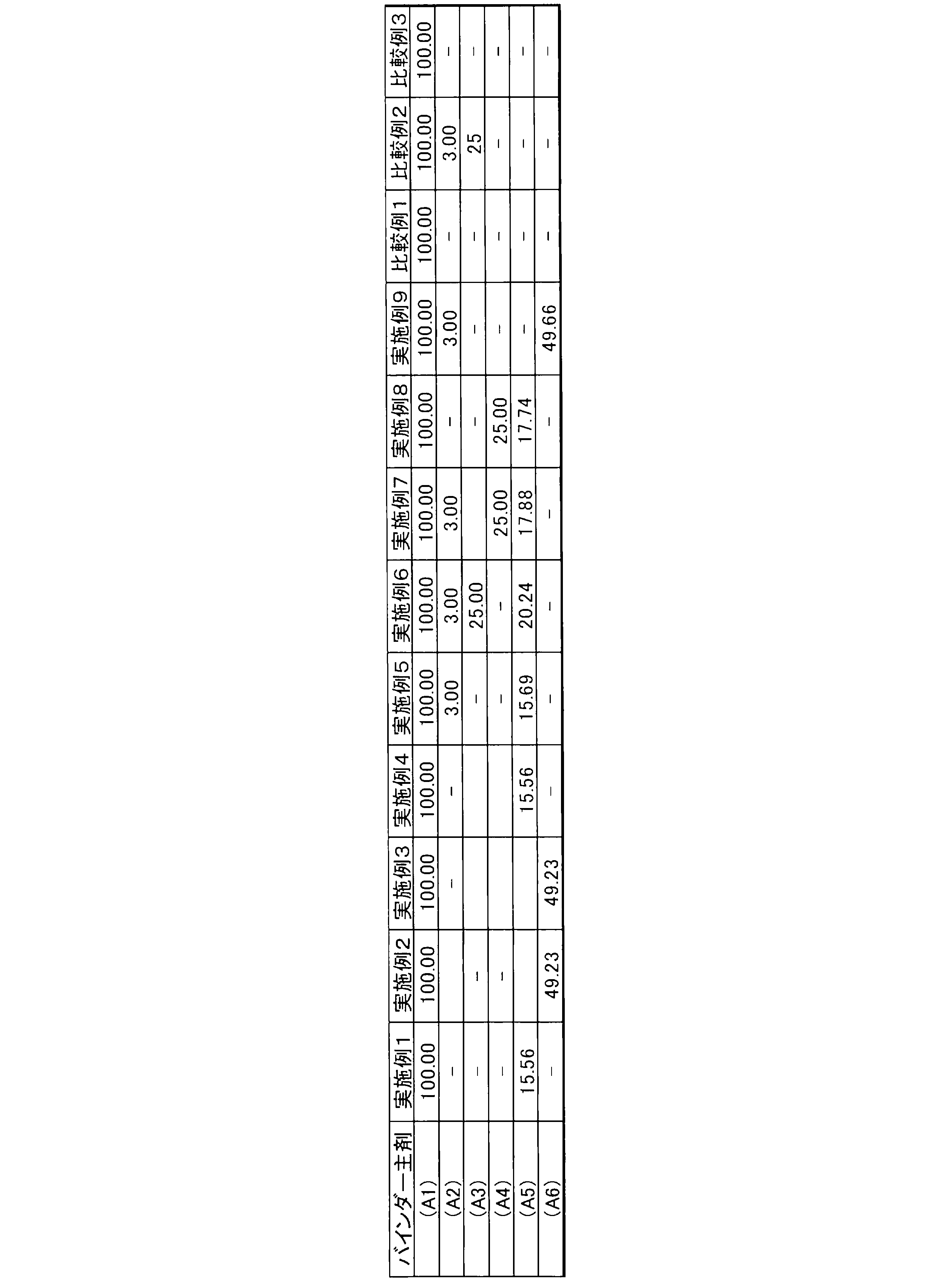
- ⁇ Preparation of binder main agent> The following materials were mixed to prepare a composition for preparing a binder base material, which was held at 100 to 120 ° C. for 4 to 6 hours to prepare a binder base material.
- the detailed formulation for preparing the composition for preparing the binder main component is shown in Table 1.
- Binder Main Agent (A1) Both ends hydroxyl group modified dimethyl silicone oil (A2) One end diol modified silicone oil (A3) Carbonate diol (A4) Hydrogenated butadiene diol (A5) Isocyanate compound (Adduct type isocyanate) (A6) Isocyanate compound (Nurate type isocyanate)
- ⁇ Adhesive layer> Silane coupling agent (F2) Organic titanium compound (titanium oligomer) (F3) Organozirconium compound (zirconium tributoxy monoacetylacetonate)
- An elastic body made of a rubber material was molded on the outer peripheral surface of the shaft body by extrusion molding using a rubber composition formed of silicone rubber.
- the rubber composition formed from silicone rubber was heated at 360 ° C. for 5 minutes using an infrared heating furnace (IR furnace), and further heated at 200 ° C. for 4 hours using a gear oven. Cured.
- IR furnace infrared heating furnace
- an elastic layer made of a cured product of the rubber composition was formed on the outer peripheral surface of the shaft treated with the primer.
- the elastic layer was a solid layer, and the thickness of the elastic layer was 3.50 mm.
- the resistance value of the elastic layer was measured using an electric resistance value measuring device R8340 ULTRA HIGH RESISTANCE METER (manufactured by ADVANTEST Co., Ltd.), it was 1.0 ⁇ 10 5 ⁇ .
- the adhesive constituting the adhesive layer shown in Table 2 was applied according to each category of Examples and Comparative Examples, and then the mixed solution of (A) to (D) shown in Table 2 was applied by a spray method. By heating the applied mixed liquid at 150 to 170 ° C. for 30 minutes, a surface layer was formed on the elastic layer. The thickness of the surface layer was 10 ⁇ m.
- the print density and the filming amount of each of the manufactured developing rollers were measured as follows.
- the image forming apparatus used was model number: HL-L2360DN (manufactured by Brother Industries, Ltd.).
- As the developing roller of the image forming apparatus each manufactured developing roller was mounted in the developing apparatus. Then, a solid image was formed under the conditions of a temperature of 23 ° C. and a humidity of 55%, and the print evaluation was confirmed.
- the filming condition after printing 4000 sheets and the print density after printing 4000 sheets (the density step ratio between the initial print forming portion and the final print forming portion of solid printing) were evaluated.
- An X-Rite 500 spectrodensitometer manufactured by X-Rite was used for the concentration measurement.
- the print density was evaluated according to the following evaluation criteria. In this test, the print density is evaluated as A or B when it is evaluated. A: When the density step ratio is 96 to 100% and the printing dots are clean B: When the density step ratio is 92 to 95% and there are other problems (coarse printing dots) C : When the density step ratio is 91% or less and there are other problems
- Toner adhesion was evaluated by the amount of developer adhered. Specifically, after sucking the developer adhering to the surface of the developing roller after printing 4000 sheets, the mass transferred to the filming weight measuring jig was measured. For the filming evaluation, the mass of the transferred developer was evaluated according to the following criteria. In this test, the filming amount is evaluated as A or B for the evaluation. A: 0 mg or more and 0.003 mg or less B: 0.003 mg or more and 0.006 mg or less C: 0.006 mg or more
- the mixed solution for forming the surface layer was left at room temperature for 0 to 12 hours, the viscosity was measured every hour, and the stability was evaluated. If the viscosity was 80 mPa ⁇ s or more within 8 hours, the viscosity was C, and if the viscosity was 50 mPa ⁇ s or more and less than 80 mPa ⁇ s between 0 and 8 hours, the viscosity was B. What was suppressed below 2050 mPa ⁇ s was designated as A. In the present invention, A or higher was passed.
Landscapes
- Engineering & Computer Science (AREA)
- General Engineering & Computer Science (AREA)
- Physics & Mathematics (AREA)
- General Physics & Mathematics (AREA)
- Mechanical Engineering (AREA)
- Rolls And Other Rotary Bodies (AREA)
- Dry Development In Electrophotography (AREA)
Abstract
軸体と、軸体の外周面上に設けられる弾性層と、弾性層より外側に設けられる表層と、を備え、表層が、下記(A)成分から(D)成分の混合物を塗布して硬化したものである、弾性ローラ;(A)両末端変性シリコーンオイル及びイソシアネート化合物を含む組成物を重合したバインダー主剤、(B)ブロックイソシアネート化合物、(C)粒子径が0.2μm以上10μm以下である、シリコーンゴム粒子及び/又はアクリル粒子、(D)希釈溶剤。
Description
本発明は、弾性ローラに関する。
電子写真方式を採用する複写機、プリンター、ファクシミリ等の画像形成装置に用いられる現像ローラは、静電潜像が形成された像担持体に現像剤を搬送する機能を持つ。現像ローラが有する現像剤搬送性は、画像形成装置の品質、特に印字濃度に影響する。したがって、現像ローラの表面に凹凸を形成するとともに、現像ローラを構成する各種材料の電気的特性を調整し、これにより、現像ローラの現像剤搬送性を向上させることが検討されている。
ここで、現像ローラは、長期間使用された場合、その表面に現像剤が固着することがある(「フィルミング」という)。このようなフィルミングは、例えば、現像剤を帯電又は付着させる際に弾性ローラと圧接するブレード等の摺動ストレスによって現像剤が変形し、又は破壊され、さらに、ブレード等との摩擦熱による現像剤の溶融等に起因して生じるものと考えられている。従来、現像ローラの製造にあたっては、フィルミングの発生を極力抑制し、これにより、耐久印字性能が安定化された弾性ローラを提供することが求められていた。
従来公知の現像ローラとして、例えば、特許文献1には、(A)ポリオール、イソシアネート化合物、及び反応性シリコーンオイルを含む液状バインダーと、(B)シリコーンゴム粒子と、(C)希釈溶剤と、を含む混合物を塗布して硬化してなる表層を備えた、弾性ローラが開示されている。
ここで、特許文献1のように、反応性シリコーンオイル及びイソシアネート化合物を含有する液状バインダーを使用した場合、液状バインダー調製からの時間の経過に伴って、架橋反応が進行して、液状バインダーの粘度が向上し、弾性ローラ製造の作業性が低下する問題があった。
本発明は、上記事情に鑑みてなされたものであり、フィルミングの発生が良好に抑制されるとともに、製造にあたっての作業性に優れ、良好な生産性を有する弾性ローラを提供することを目的とする。
本発明は、上記事情に鑑みてなされたものであり、フィルミングの発生が良好に抑制されるとともに、製造にあたっての作業性に優れ、良好な生産性を有する弾性ローラを提供することを目的とする。
本発明の発明者らは、鋭意研究を行った結果、両末端変性シリコーンオイル及びイソシアネート化合物からなる組成物を重合したバインダー主剤と、ブロックイソシアネート化合物と、を少なくとも含む混合物を塗布及び硬化することにより、表層を形成した弾性ローラが、フィルミングの発生が良好に抑制され、生産性にも優れることを見出し、本発明を完成するに至った。具体的には、本発明は、以下のものを提供する。
(1)軸体と、前記軸体の外周面上に設けられる弾性層と、弾性層より外側に設けられる表層と、を備え、前記表層が、下記(A)成分から(D)成分の混合物を塗布して硬化したものである、弾性ローラ;
(A)両末端変性シリコーンオイル及びイソシアネート化合物を含む組成物を重合したバインダー主剤、(B)ブロックイソシアネート化合物、(C)粒子径が0.2μm以上10μm以下である、シリコーンゴム粒子及び/又はアクリル粒子、(D)希釈溶剤。
(A)両末端変性シリコーンオイル及びイソシアネート化合物を含む組成物を重合したバインダー主剤、(B)ブロックイソシアネート化合物、(C)粒子径が0.2μm以上10μm以下である、シリコーンゴム粒子及び/又はアクリル粒子、(D)希釈溶剤。
(2)(A)成分が、両末端変性シリコーンオイル、片末端ジオール変性シリコーンオイル、及びイソシアネート化合物を含む組成物を重合したバインダー主剤である、(1)に記載の弾性ローラ。
(3)(A)成分が、両末端変性シリコーンオイル、片末端ジオール変性シリコーンオイル、イソシアネート化合物、並びにカーボネートポリオール及び/又は水添ブタジエンポリオールを含む組成物を重合させたバインダー主剤である、(1)に記載の弾性ローラ。
(4)(B)成分が、メチルエチルケトンオキシムで末端封止されたイソシアヌレート型ブロックイソシアネート、又はメチルエチルケトンオキシムで末端封止されたアダクト型ブロックイソシアネートである、(1)から(3)のいずれかに記載の弾性ローラ。
(5)さらに、弾性層及び表層の間に接着層を有し、接着層が、有機チタン化合物及び/又は有機ジルコニウム化合物を含有する、(1)から(4)のいずれかに記載の弾性ローラ。
本発明の弾性ローラは、表層を形成する際に、両末端変性シリコーンオイル及びイソシアネート化合物からなる組成物を重合したバインダー主剤と、ブロックイソシアネート化合物と、を少なくとも含む混合物を塗布及び硬化する。このため、混合物の調製後の、イソシアネート化合物と水酸基を有するバインダー主剤との反応が容易に制御可能であるため、混合物の粘度が向上せず、作業性に優れる。さらに、この混合物から形成される弾性ローラの表層は、比誘電率が低いものとなるため、長期間使用したとしても、フィルミングの発生が良好に抑制されたものとなる。
以下、本発明について、図面を参照して詳細に説明する。
<弾性ローラ>
本発明の弾性ローラ1は、軸体2と、軸体2の外表面に設けられる弾性層3と、弾性層3より外側に設けられる表層4と、を備える。本発明の弾性ローラ1は、好ましくは、現像ローラとして用いられるものであるが、そのような用途に限定されるものではない。
本発明の弾性ローラ1は、軸体2と、軸体2の外表面に設けられる弾性層3と、弾性層3より外側に設けられる表層4と、を備える。本発明の弾性ローラ1は、好ましくは、現像ローラとして用いられるものであるが、そのような用途に限定されるものではない。
[軸体]
軸体2は、好ましくは、導電特性を有する、従来公知の弾性ローラに用いられる軸体を用いることができる。軸体2は、例えば、鉄、アルミニウム、ステンレス鋼、及び真鍮からなる群より選択される少なくとも1種の金属で構成されていることが好ましい。なお、このような軸体2は、一般に、「芯金」の名称でも知られている。
軸体2は、好ましくは、導電特性を有する、従来公知の弾性ローラに用いられる軸体を用いることができる。軸体2は、例えば、鉄、アルミニウム、ステンレス鋼、及び真鍮からなる群より選択される少なくとも1種の金属で構成されていることが好ましい。なお、このような軸体2は、一般に、「芯金」の名称でも知られている。
軸体2は、絶縁性樹脂を含むものであってもよい。絶縁性樹脂は、例えば、熱可塑性樹脂であってもよく、熱硬化性樹脂であってもよい。軸体2は、例えば、絶縁性樹脂からなる芯体と、この芯体上に設けられたメッキ層と、を備えるものであってよい。このような軸体2は、例えば、絶縁性樹脂からなる芯体にメッキを施して導電化することにより得ることができる。
軸体2は、良好な導電特性を得るために、芯金であることが好ましい。
軸体2の形状は、例えば、棒状、管状等であることが好ましい。軸体2の断面形状は、例えば、円形、楕円形であってもよく、多角形等の非円形であってもよい。軸体2の外周面には、洗浄処理、脱脂処理、プライマー処理等の処理が施されていてもよい。
軸体2の軸方向の長さは特に限定されず、設置される画像形成装置の形態に応じて適宜調整してもよい。また、軸体2の直径(外接円の直径)も特に限定されず、設置される画像形成装置の形態に応じて適宜調整すればよい。
[弾性層]
弾性層3は、シリコーンゴムを含むゴム材料から構成される。弾性層3がシリコーンゴムを含むことで、圧縮永久歪みを低減することができるとともに、低温環境下における柔軟性に優れるという効果が得られる。
弾性層3は、シリコーンゴムを含むゴム材料から構成される。弾性層3がシリコーンゴムを含むことで、圧縮永久歪みを低減することができるとともに、低温環境下における柔軟性に優れるという効果が得られる。
シリコーンゴムとしては、例えば、ジメチルポリシロキサン、ジフェニルポリシロキサン等のオルガノポリシロキサンの架橋物が挙げられる。また、シリコーンゴムは、これらの変性物であってもよい。
弾性層3は、主としてシリコーンゴムを含んでいることが好ましい。具体的には、弾性層3におけるシリコーンゴムの含有量が、弾性層3の全質量を基準として、30質量%以上であることが好ましく、40質量%以上であることがより好ましく、60質量%以上であることが更に好ましい。
弾性層3は、ゴム材料以外の成分を含んでいてもよい。例えば、弾性層3は、導電性付与剤を更に含んでいてもよい。導電性付与剤は、弾性層3に導電性を付与するための成分であればよく、特に限定されるものではない。導電性付与剤としては、例えば、導電性カーボン、ゴム用カーボン類、金属、導電性ポリマー等を含む導電性粉末等を挙げることができる。導電性粉末としては、カーボンブラックを用いることが好ましく、カーボンブラックとしては、例えば、ケッチェンブラック(登録商標)等のファーネスブラック、アセチレンブラック、チャンネルブラック、サーマルブラック等を挙げることができる。
弾性ローラ1においては、軸体2の軸方向の両端で軸体2の外周面が露出するように弾性層3が形成されている。すなわち、軸体2の外周面上には、弾性層3が設けられていない領域が存在している。しかしながら、本発明における、弾性層3の態様はこのような態様に限定されるものではなく、弾性層3が、軸体2の外周面の全面を覆うように設けられていてもよい。
弾性層3は、中実な層であってよく、層の内部に中空を有していないことが好ましい。本明細書において「中実」とは、層の内部に0.1mm2/個以上の中空を有しないことを意味する。
弾性層3のJIS A硬度は、20以上55以下であることが好ましい。弾性層のJIS A硬度(JIS K 6301)が上記範囲内であることにより、弾性ローラと被当接体(例えば、感光体等の像担持体)との接触面積(ニップ幅)が大きくなるため、転写効率、帯電効率、及び現像効率等の性能が一層向上する傾向にある。また、被当接体に機械的ダメージを与える可能性が低減される。
弾性層3の厚さは、被当接体との当接状態において被当接体との均一なニップ幅を確保することができる等の観点から、0.5mm以上10mm以下であることが好ましく、1mm以上5mm以下であることがより好ましい。なお、本明細書において「厚さ」とは、弾性ローラ1の軸方向に垂直な方向の厚さを意味する。弾性層3の外径は、特に限定されない。外径は、例えば、5mm以上20mm以下であってもよい。なお、本明細書において、「外径」とは、弾性ローラ1の軸方向に垂直な断面における外径を意味する。弾性層3の厚さ及び外径は、弾性層3を形成する際に用いるゴム組成物の量を調整する、弾性層3の形成後に弾性層3の外周面を研磨又は研削する、等の方法により調整することができる。
弾性層3の外周面には、プライマー処理、コロナ処理、プラズマ処理、エキシマ処理、UV処理、イトロ処理、フレーム処理等の表面処理が施されていてもよい。
弾性層3は、以下に示すゴム組成物の硬化物であってもよい。
(ゴム組成物)
上記のゴム組成物は、架橋によりシリコーンゴムを構成するゴム成分を含有することが好ましい。このようなゴム成分としては、例えば、オルガノポリシロキサン等のシリコーン生ゴムが挙げられる。
上記のゴム組成物は、架橋によりシリコーンゴムを構成するゴム成分を含有することが好ましい。このようなゴム成分としては、例えば、オルガノポリシロキサン等のシリコーン生ゴムが挙げられる。
オルガノポリシロキサンとしては、例えば、下記平均組成式で表されるオルガノポリシロキサン等を挙げることができる。
RnSiO(4-n)/2
[Rは、置換されていてもよい一価の炭化水素基を示す。炭化水素基の炭素数は、1以上12以下が好ましく、1以上8以下がより好ましい。複数のRは同一でも異なっていてもよい。nは1.95以上2.05以下の数を示す。]
RnSiO(4-n)/2
[Rは、置換されていてもよい一価の炭化水素基を示す。炭化水素基の炭素数は、1以上12以下が好ましく、1以上8以下がより好ましい。複数のRは同一でも異なっていてもよい。nは1.95以上2.05以下の数を示す。]
上記式中のRとしては、例えば、メチル基、エチル基、プロピル基、ブチル基、ヘキシル基、ドデシル基等のアルキル基、シクロヘキシル基等のシクロアルキル基、ビニル基、アリル基、ブテニル基、ヘキセニル基等のアルケニル基、フェニル基、トリル基等のアリール基、β-フェニルプロピル基等のアラルキル基、及びクロロメチル基、トリフルオロプロピル基、シアノエチル基等、上記の基の炭素原子に結合した水素原子の一部又は全部をハロゲン原子又はシアノ基等で置換された有機基を挙げることができる。
オルガノポリシロキサンは、一分子中にケイ素原子と結合するアルケニル基を少なくとも2個含有するオルガノポリシロキサンであることが好ましい。例えば、上記式中、少なくとも2個のRが上記アルケニル基を有することが好ましい。オルガノポリシロキサンは、ビニル基を有することが更に好ましい。
オルガノポリシロキサンの具体例としては、ジメチルポリシロキサン、ジフェニルポリシロキサン等が挙げられる。オルガノポリシロキサンは、分子鎖末端がトリメチルシリル基、ジメチルビニルシリル基、ジメチルヒドロキシシリル基、トリビニルシリル基等で封鎖されていることが好ましい。
ゴム組成物は、各種の添加剤を含有していてもよい。このような添加剤としては、例えば、導電性付与剤、鎖延長剤、及び架橋剤等の助剤、付加反応触媒等の触媒、反応制御剤、分散剤、老化防止剤、酸化防止剤、充填材、顔料、着色剤、加工助剤、軟化剤、可塑剤、乳化剤、耐熱性向上剤、難燃性向上剤、受酸剤、熱伝導性向上剤、離型剤、溶剤などを挙げることができる。
ゴム組成物は、液状のゴム組成物であってよく、ミラブル型のゴム組成物であってよい。
[表層]
表層4は、弾性ローラ1の最表面に設けられるものである。弾性ローラ1におけるフィルミングの発生を防止するためには、少なくとも、表層4の特性を調整する必要がある。本発明においては、表層4は、下記(A)成分から(D)成分の混合物を塗布して硬化したものである。
(A)両末端変性シリコーンオイル及びイソシアネート化合物からなる組成物を重合したバインダー主剤、
(B)ブロックイソシアネート化合物、
(C)粒子径が0.2μm以上10μmである、シリコーンゴム粒子及び/又はアクリル粒子、
(D)希釈溶剤。
表層4は、弾性ローラ1の最表面に設けられるものである。弾性ローラ1におけるフィルミングの発生を防止するためには、少なくとも、表層4の特性を調整する必要がある。本発明においては、表層4は、下記(A)成分から(D)成分の混合物を塗布して硬化したものである。
(A)両末端変性シリコーンオイル及びイソシアネート化合物からなる組成物を重合したバインダー主剤、
(B)ブロックイソシアネート化合物、
(C)粒子径が0.2μm以上10μmである、シリコーンゴム粒子及び/又はアクリル粒子、
(D)希釈溶剤。
なお、上記の混合物は、加熱硬化される前には液状の状態のものである。
((A)バインダー主剤)
バインダー主剤は、両末端変性シリコーンオイル及びイソシアネート化合物からなる組成物を重合させたものである。この組成物は、必要に応じて、更に、片末端ジオール変性シリコーンオイル、並びにカーボネートポリオール及び/又は水添ブタジエンポリオールを含んでいてもよいが、カーボネートポリオール及び水添ブタジエンポリオール以外のポリオールを含有していない必要がある。この組成物にカーボネートポリオール及び水添ブタジエンポリオール以外のポリオールが含有される場合、後述する(B)成分のブロックイソシアネート化合物との相溶性が低下し、上記の混合物の硬化不良を起こすこととなる。
バインダー主剤は、両末端変性シリコーンオイル及びイソシアネート化合物からなる組成物を重合させたものである。この組成物は、必要に応じて、更に、片末端ジオール変性シリコーンオイル、並びにカーボネートポリオール及び/又は水添ブタジエンポリオールを含んでいてもよいが、カーボネートポリオール及び水添ブタジエンポリオール以外のポリオールを含有していない必要がある。この組成物にカーボネートポリオール及び水添ブタジエンポリオール以外のポリオールが含有される場合、後述する(B)成分のブロックイソシアネート化合物との相溶性が低下し、上記の混合物の硬化不良を起こすこととなる。
(両末端変性シリコーンオイル)
両末端変性シリコーンオイルは、いわゆる、反応性シリコーンオイルの1種であり、イソシアネート化合物、及び後述する(B)成分のブロックイソシアネート化合物と重合する特性を有する。よって、両末端変性シリコーンオイルは、アミノ基(1級又は2級アミノ基)、メルカプト基、又はヒドロキシル基により、シリコーン鎖の両末端が変性されていることが好ましい。これらの両末端変性シリコーンオイルは、両末端アミノ変性シリコーンオイル、両末端メルカプト変性シリコーンオイル、両末端カルボキシル変性シリコーンオイル、両末端フェノール変性シリコーンオイル、両末端カルビノール変性シリコーンオイルとして市販されている。
両末端変性シリコーンオイルは、いわゆる、反応性シリコーンオイルの1種であり、イソシアネート化合物、及び後述する(B)成分のブロックイソシアネート化合物と重合する特性を有する。よって、両末端変性シリコーンオイルは、アミノ基(1級又は2級アミノ基)、メルカプト基、又はヒドロキシル基により、シリコーン鎖の両末端が変性されていることが好ましい。これらの両末端変性シリコーンオイルは、両末端アミノ変性シリコーンオイル、両末端メルカプト変性シリコーンオイル、両末端カルボキシル変性シリコーンオイル、両末端フェノール変性シリコーンオイル、両末端カルビノール変性シリコーンオイルとして市販されている。
ここで、本発明で用いられる好ましい両末端変性シリコーンオイルとしては、以下の一般式(1)で示される両末端変性シリコーンオイルを挙げることができる。

一般式(1)において、Rは、-C3H6OC2H4OH、又は-C3H6OCH2-C(CH2OH)2C2H5を示し、nは、20以下の整数を表す。
一般式(1)で示される両末端変性シリコーンオイルの中でも、特に、両末端のRが、-C3H6OC2H4OHであり、nが約10であるシリコーンオイルを用いることが好ましい。このようなシリコーンオイルについては、市販のものを適宜入手することができる。
なお、一般式(1)においては、ケイ素原子に結合する官能基は、メチル基となっているが、このメチル基が水素原子で置換された両末端変性シリコーンオイルであってもよい。
表層4を形成するための混合物に両末端変性シリコーンオイルを含有することにより、表層に適度な弾性を付与することができるとともに、表層4の電気的特性を調整して、表層の比誘電率を低下させることができ、フィルミングの発生を有効に抑制することができる。
(片末端ジオール変性シリコーンオイル)
片末端ジオール変性シリコーンオイルは、両末端変性シリコーンオイルと同様に、反応性シリコーンオイルであるが、シリコーン鎖の一方の末端に、2つのヒドロキシル基が結合しているものである。通常、両末端変性シリコーンオイルとイソシアネート化合物とを重合させた場合、直鎖状のポリウレタンが生成するが、片末端ジオール変性シリコーンオイルを併用することにより、ポリウレタンに分岐鎖が導入され、弾性ローラ1のナノレベルの微細な粗さを向上させることができる。
片末端ジオール変性シリコーンオイルは、両末端変性シリコーンオイルと同様に、反応性シリコーンオイルであるが、シリコーン鎖の一方の末端に、2つのヒドロキシル基が結合しているものである。通常、両末端変性シリコーンオイルとイソシアネート化合物とを重合させた場合、直鎖状のポリウレタンが生成するが、片末端ジオール変性シリコーンオイルを併用することにより、ポリウレタンに分岐鎖が導入され、弾性ローラ1のナノレベルの微細な粗さを向上させることができる。
片末端ジオール変性シリコーンオイルとしては、以下の一般式(2)で示される片末端変性シリコーンオイルを挙げることができる。

一般式(2)において、R’は、-C3H6OCH2-C(CH2OH)2C2H5を示し、nは、20以下の整数を表す。
一般式(2)で示される片末端ジオール変性シリコーンオイルの中でも、特に、nが約10であるシリコーンオイルを用いることが好ましい。なお、一般式(2)においては、ケイ素原子に結合する官能基は、メチル基となっているが、このメチル基が水素原子で置換されたシリコーンオイルであってもよい。
本発明において、バインダー主剤の調製のために使用する片末端ジオール変性シリコーンオイルは、両末端変性シリコーンオイル100質量部に対して、0.1質量部以上10質量部以下であることが好ましく、2質量部以上6質量部以下であることがより好ましい。両末端変性シリコーンオイルに対する片末端ジオール変性シリコーンオイルの使用量を上記の範囲内のものとすることにより、表層4の表面粗さを調整することにより、現像性能を良好に維持ししつつ、フィルミングを効果的に防止することができる。
(イソシアネート化合物)
本発明において、バインダー主剤の調製のために用いるイソシアネート化合物としては、シリコーンオイルに導入された反応性基との反応性を有するものであれば特に限定されるものではないが、例えば、ジフェニルメタンジイソシアネート(MDI)、トリレンジイソシアネート(TDI)、ヘキサメチレンジイソシアネート(HDI)等のジイソシアネート、及びそれらのビュレット変性体、イソシアヌレート変性体、ウレタン変性体等を挙げることができる。これらのイソシアネート化合物の中でも、ヘキサメチレンジイソシアネート、及びそのビュレット変性体、イソシアヌレー卜変性体、ウレタン変性体等を使用することが好ましい。イソシアネート化合物は、その分子鎖が長いほど、より高い柔軟性を有するポリウレタンを生成することができる。
本発明において、バインダー主剤の調製のために用いるイソシアネート化合物としては、シリコーンオイルに導入された反応性基との反応性を有するものであれば特に限定されるものではないが、例えば、ジフェニルメタンジイソシアネート(MDI)、トリレンジイソシアネート(TDI)、ヘキサメチレンジイソシアネート(HDI)等のジイソシアネート、及びそれらのビュレット変性体、イソシアヌレート変性体、ウレタン変性体等を挙げることができる。これらのイソシアネート化合物の中でも、ヘキサメチレンジイソシアネート、及びそのビュレット変性体、イソシアヌレー卜変性体、ウレタン変性体等を使用することが好ましい。イソシアネート化合物は、その分子鎖が長いほど、より高い柔軟性を有するポリウレタンを生成することができる。
本発明において、バインダー主剤の調製のために使用するイソシアネート化合物は、両末端変性シリコーンオイル100質量部に対して、5質量部以上85質量部以下であることが好ましく、15質量部以上75質量部以下であることがより好ましい。両末端変性シリコーンオイルに対するイソシアネート化合物の使用量を上記の範囲内のものとすることにより、表層4を形成するための混合物の粘度を好適なものとして、作業性を向上させることができる。
(カーボネートポリオール、水添ブタジエンポリオール)
カーボネートポリオール及び水添ブタジエンポリオールは、上述のイソシアネート化合物や後述するブロックイソシアネート化合物と反応して、ポリウレタンを形成するものであるが、他のポリオールとは異なり、ブロックイソシアネート化合物との相溶性に優れている。本発明の発明者らは、他のポリオールを使用した場合、ブロックイソシアネートとの間で層分離を起こし、硬化不良につながるため、カーボネートポリオール及び水添ブタジエンポリオール以外のポリオールは、バインダー主剤を形成するための組成物には使用できないことを見出したが、カーボネートポリオール及び水添ブタジエンポリオールについては、ブロックイソシアネート化合物との相溶性が良好で、このような問題を引き起こさないことが判明した。よって、これらのポリオールを使用することにより、良好な特性を有する表層4を形成することができる。
カーボネートポリオール及び水添ブタジエンポリオールは、上述のイソシアネート化合物や後述するブロックイソシアネート化合物と反応して、ポリウレタンを形成するものであるが、他のポリオールとは異なり、ブロックイソシアネート化合物との相溶性に優れている。本発明の発明者らは、他のポリオールを使用した場合、ブロックイソシアネートとの間で層分離を起こし、硬化不良につながるため、カーボネートポリオール及び水添ブタジエンポリオール以外のポリオールは、バインダー主剤を形成するための組成物には使用できないことを見出したが、カーボネートポリオール及び水添ブタジエンポリオールについては、ブロックイソシアネート化合物との相溶性が良好で、このような問題を引き起こさないことが判明した。よって、これらのポリオールを使用することにより、良好な特性を有する表層4を形成することができる。
カーボネートポリオール及び/又は水添ブタジエンポリオールは、両末端変性シリコーンオイル100質量部に対して、5質量部以上40質量部以下であることが好ましく、10質量部以上30質量部以下であることがより好ましい。これらのポリオールとしては、市販のものを使用することができる。
((B)ブロックイソシアネート化合物)
ブロックイソシアネート化合物は、ポリウレタンの調製に通常使用される各種イソシアネート化合物(例えば、芳香族イソシアネート化合物、脂肪族イソシアネート化合物、脂環式イソシアネート化合物)を、アダクト型又はイソシアヌレート型に誘導したものであって、メチルエチルケトンオキシムにより末端封止されたイソシアヌレート型ブロックイソシアネート又はアダクト型ブロックイソシアネートを使用することができる。
ブロックイソシアネート化合物は、ポリウレタンの調製に通常使用される各種イソシアネート化合物(例えば、芳香族イソシアネート化合物、脂肪族イソシアネート化合物、脂環式イソシアネート化合物)を、アダクト型又はイソシアヌレート型に誘導したものであって、メチルエチルケトンオキシムにより末端封止されたイソシアヌレート型ブロックイソシアネート又はアダクト型ブロックイソシアネートを使用することができる。
これらのイソシアネート化合物として、芳香族イソシアネート化合物としては、例えば、2,4-トリレンジイソシアネート(2,4-TDI)、2,6-トリレンジイソシアネート(2,6-TDI)、4,4’-ジフェニルメタンジイソシアネート(4,4’-MDI)、2,4’-ジフェニルメタンジイソシアネート(2,4’-MDI)、1,4-フェニレンジイソシアネート、ポリメチレンポリフェニレンポリイソシアネート、トリジンジイソシアネート(TODI)、1,5-ナフタレンジイソシアネート(NDI)、3,3’-ジメチルビフェニル-4,4’-ジイソシアネート等を挙げることができる。また、脂肪族イソシアネート化合物としては、例えば、ヘキサメチレンジイソシアネート(HDI)、トリメチルヘキサメチレンジイソシアネート(TMHDI)、リジンジイソシアネート、ノルボルネンジイソシアナートメチル(NBDI)、キシリレンジイソシアネート(XDI)、テトラメチルキシリレンジイソシアネート(TMXDI)等を挙げることができる。さらに、脂環式ポリイソシアネートとしては、例えば、トランスシクロヘキサン-1,4-ジイソシアネート、イソホロンジイソシアネート(IPDI)、H6XDI(水添XDI)、H12MDI(水添MDI)、4,4’-ジシクロへキシルメタンジイソシアネート等を挙げることができる。
本発明においては、ポリウレタンの調製にブロックイソシアネート化合物を使用しているため、表層4を形成するための混合液の調製後、時間が経過しても、この混合液の粘度が上昇せず、表層4の形成の際の作業性が良好に維持される。この際、バインダー主剤の調製にあたって、カーボネートポリオール及び水添ブタジエンポリオール以外のポリオールを使用していないので、ブロックイソシアネート化合物と、他の成分との相溶性が良好に維持され、硬化不良を生じることがない。
本発明において、表層4を形成するために使用する混合液におけるブロックイソシアネート化合物の使用量は、バインダー主剤100質量部に対して、5質量部以上80質量部以下であることが好ましく、10質量部以上70質量部以下であることがより好ましい。ブロックイソシアネート化合物の使用量を上記範囲内のものとすることにより、形成される表層4の硬度を好適な範囲に維持することができる。
((C)シリコーンゴム粒子、アクリル粒子)
表層4を形成するための混合液は、シリコーンゴム粒子及び/又はアクリル粒子を含有する。このシリコーンゴム粒子及びアクリル粒子の粒子径は、0.2μm以上10μm以下であることが好ましく、0.8μm以上5μm以下であることがより好ましい。シリコーンゴム粒子及びアクリル粒子の粒子径を上記の範囲内のものとすることにより、弾性ローラ1の表面粗さが適切に維持され、現像剤搬送性が良好に保たれる一方で、解像度を高い水準に維持して、画質の悪化を防止することができる。シリコーンゴム粒子及びアクリル粒子の粒径は、弾性ローラ1を切断処理した後に、顕微鏡により断面を観察することにより測定することができる。
表層4を形成するための混合液は、シリコーンゴム粒子及び/又はアクリル粒子を含有する。このシリコーンゴム粒子及びアクリル粒子の粒子径は、0.2μm以上10μm以下であることが好ましく、0.8μm以上5μm以下であることがより好ましい。シリコーンゴム粒子及びアクリル粒子の粒子径を上記の範囲内のものとすることにより、弾性ローラ1の表面粗さが適切に維持され、現像剤搬送性が良好に保たれる一方で、解像度を高い水準に維持して、画質の悪化を防止することができる。シリコーンゴム粒子及びアクリル粒子の粒径は、弾性ローラ1を切断処理した後に、顕微鏡により断面を観察することにより測定することができる。
本発明において使用するシリコーンゴム粒子、及びアクリル粒子は、100℃以上の温度でも変形又は溶融等しない耐熱性を有することが好ましく、130℃から180℃での耐熱性を有することがより好ましい。これにより、表層4の架橋温度においても、これらのシリコーンゴム粒子、及びアクリル粒子が、変形することを防止することができる。シリコーンゴム粒子、及びアクリル粒子の耐熱性は、メルトフローインデクサーにおいて、圧力と熱を与えてもシリコーンゴム粒子やアクリル粒子が溶けて流れ出すことがないことを確認することにより、評価することができる。
シリコーンゴム粒子及びアクリル粒子の硬度は、デュロメータA(瞬時)(JIS K 6253:1997)により測定して20度以上80度以下であることが好ましく、50℃以上75度以下であることがより好ましい。シリコーンゴム粒子及びアクリル粒子の硬度が、上記の範囲内のものであることにより、シリコーンゴム粒子及びアクリル粒子の破壊や変形による、表層4の摩擦係数の上昇や粘着の発生を効果的に防止できるとともに、表層4の硬度が上がりすぎることによる、表層4におけるクラックや割れの発生を防止することもでき、トナーに過剰なストレスを与えることも防止できる。
シリコーンゴム粒子、及びアクリル粒子は、表層4中に存在(埋没)していてもよく、その一部が表層4の表面に突出していてもよい。また、表層4において不均一に分散していてもよく、表層4の表面側に偏在していてもよい。
シリコーンゴム粒子、及びアクリル粒子のうち、シリコーンゴム粒子については、ジメチルポリシロキサン等、オルガノポリシロキサン、ポリオルガノシルセスオキサンを架橋した構造が好ましく、アクリル粒子としては、市販のアクリル粒子を使用することができる。
なお、シリコーンゴム粒子については、有機基として、メチル基、エチル基、プロピル基、ブチル基等のアルキル基;フェニル基、トリル基等のアリール基;ビニル基、アリル基等のアルケニル基;β-フェニルエチル基、β-フェニルプロピル基等のアラルキル基;クロロメチル基、3,3,3-トリフルオロプロピル基等の1価ハロゲン化炭化水素基;エポキシ基、アミノ基、メルカプト基、アクリロキシ基、メタクリロキシ基等の反応性基含有有機基から選択される1種又は2種以上の炭素数1以上20以下の1価の有機基から選択される基を有するオルガノポリシロキサン又はオルガノポリシルセスキオキサンから調製することが好ましく、これら、オルガノポリシロキサン又はオルガノポリシルセスキオキサンから調製される粒子を、オルガノアルコキシシランで表面処理した粒子であってもよい。このようなシリコーンゴム粒子としては、例えば、信越化学工業株式会社製の「KMP-597」や、東レ・ダウコーニング株式会社製の「EP-5500」、「EP-2600」、「EP-2601」、「E-2720」、「DY 33-430M」、「EP-2720」、「EP-9215Cosmetic Powder」、「9701Cosmetic Powder」等を使用することができる。
シリコーンゴム粒子及び/又はアクリル粒子の使用量は、バインダー主剤100質量部に対して、15質量部以上50質量部以下であることが好ましく、20質量部以上30質量部以下であることがより好ましい。シリコーンゴム粒子及び/又はアクリル粒子の使用量を、上記使用量の範囲内のものとすることにより、弾性ローラ1の表面粗さが適切に維持され、現像剤搬送性が良好に保たれる一方で、解像度を高い水準に維持して、画質の悪化を防止することができる。
((D)希釈溶剤)
希釈溶剤としては、水系溶剤、及び有機系溶剤を使用することができ、求められる乾燥速度に応じて、低沸点溶剤、高沸点溶剤を組み合わせて使用することができる。
希釈溶剤としては、水系溶剤、及び有機系溶剤を使用することができ、求められる乾燥速度に応じて、低沸点溶剤、高沸点溶剤を組み合わせて使用することができる。
本発明において、表層4を形成するための混合物においては、固形分濃度が20質量%以上60質量%以下の範囲内であることが好ましく、30質量%以上50質量%以下の範囲内であることがより好ましい。固形分濃度が低いと、塗布時に液ダレが起こり易く、乾燥に時間がかかる。固形分濃度が高いと、塗布表面のザラツキを生じる、又は、厚み制御が難しくなる。
本発明において、希釈溶剤としては、上述のシリコーンゴム粒子やアクリル粒子を膨潤させる希釈溶剤を使うことが好ましい。これにより、混合液中でシリコーンゴム粒子やアクリル粒子が膨潤し、表層4を、はじきや凹みのないものとすることができるとともに、混合液中でのシリコーンゴム粒子やアクリル粒子の沈降を抑制することができる。
このような希釈溶剤としては、メチルエチルケトン(MEK)、メチルイソブチルケトン(MIBK)、テトラヒドロフラン(THF)、アセトン、酢酸エチル、酢酸ブチル、トルエン、キシレン、ヘプタン、シクロヘキサノン、イソホロン等の有機溶剤を用いることが好ましい。
[接着層]
本発明の弾性ローラ1は、軸体2と弾性層3との間、及び弾性層3と表層4との間に、接着層を備えていてもよい接着層はその電気的特性を調整することにより、弾性ローラ1としての電気的特性を調整することができ、これにより、現像ローラとしての弾性ローラ1の現像性能を良好に調整することができる。
本発明の弾性ローラ1は、軸体2と弾性層3との間、及び弾性層3と表層4との間に、接着層を備えていてもよい接着層はその電気的特性を調整することにより、弾性ローラ1としての電気的特性を調整することができ、これにより、現像ローラとしての弾性ローラ1の現像性能を良好に調整することができる。
接着層は、有機チタン化合物及び/又は有機ジルコニウム化合物を含有していることが好ましく、これらの有機金属化合物と、シランカップリング剤とを含有していることがより好ましい。有機チタン化合物及び有機ジルコニウム化合物と、シランカップリング剤とを併用することにより、弾性層3の誘電率を上昇させて、現像性能を良好に維持するとともに、弾性層3と表層4との接着性を良好なものとすることができる。有機チタン化合物としては、アルコキシ基を含有するチタン化合物、チタンキレート化合物等が挙げることができ、有機ジルコニウム化合物としては、アルコキシ基を含有するジルコニウム化合物、ジルコニウムキレート化合物等を挙げることができる。これらの、有機チタン化合物及び有機ジルコニウム化合物は、市販されているものを適宜使用することができる。
以下、本発明について、実施例を挙げて詳細に説明する。なお、本発明は、以下に示す実施例に何ら限定されるものではない。
<バインダー主剤の調製>
以下に示す材料を混合して、バインダー主剤を調製するための組成物を調製し、これを、100℃から120℃で、4時間から6時間保持して、バインダー主剤を調製した。バインダー主剤を調製するための組成物を調製する際の詳細な配合については、表1に示した。
以下に示す材料を混合して、バインダー主剤を調製するための組成物を調製し、これを、100℃から120℃で、4時間から6時間保持して、バインダー主剤を調製した。バインダー主剤を調製するための組成物を調製する際の詳細な配合については、表1に示した。
[(A)バインダー主剤を調製するための組成物]
(A1)両末端ヒドロキシル基変性ジメチルシリコーンオイル
(A2)片末端ジオール変性シリコーンオイル
(A3)カーボネートジオール
(A4)水添ブタジエンジオール
(A5)イソシアネート化合物(アダクト型イソシアネート)
(A6)イソシアネート化合物(ヌレート型イソシアネート)
(A1)両末端ヒドロキシル基変性ジメチルシリコーンオイル
(A2)片末端ジオール変性シリコーンオイル
(A3)カーボネートジオール
(A4)水添ブタジエンジオール
(A5)イソシアネート化合物(アダクト型イソシアネート)
(A6)イソシアネート化合物(ヌレート型イソシアネート)
<表層を形成するための混合液の調製>
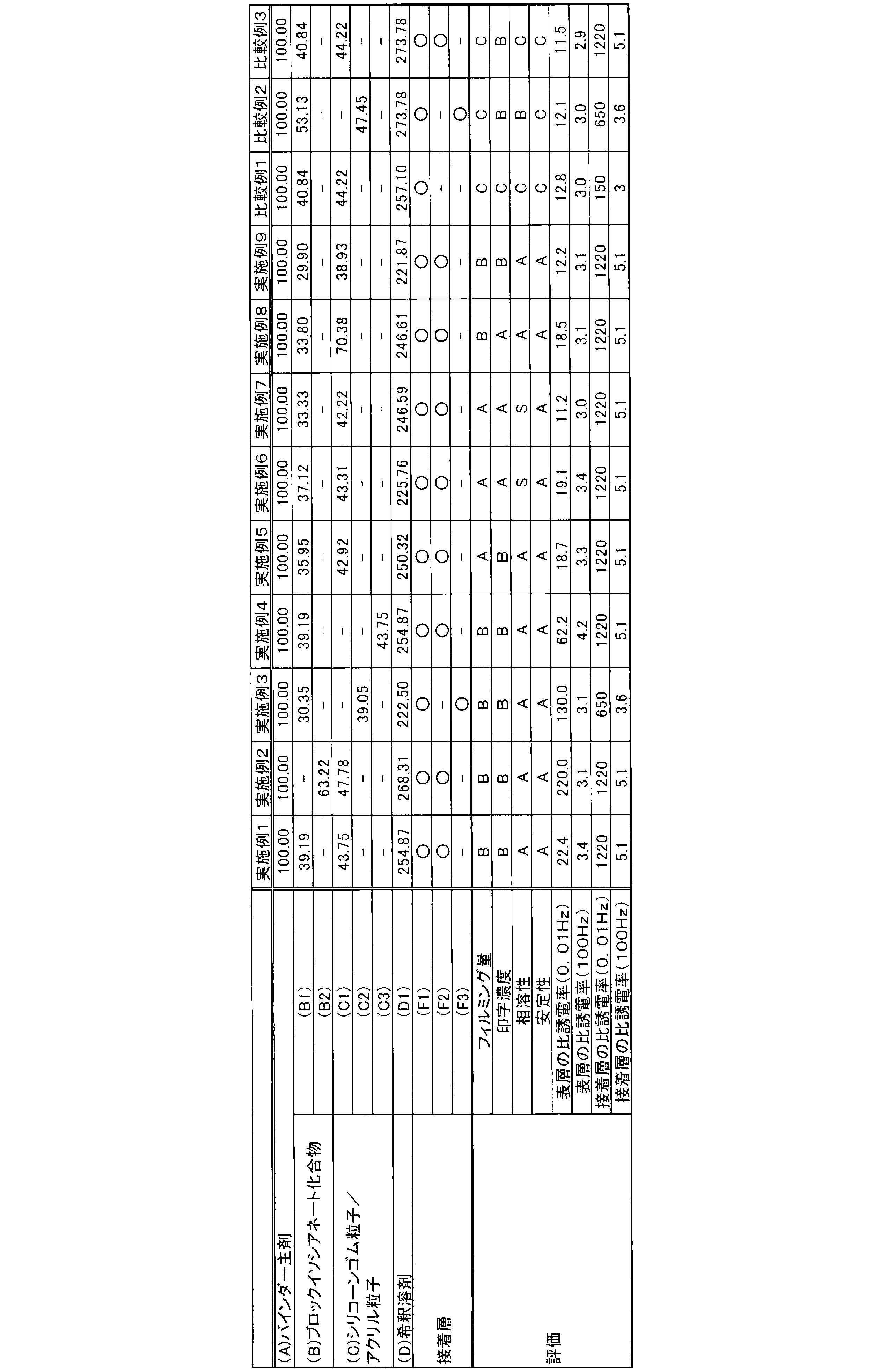
バインダー主剤と、下記に示す各材料を混合して、表層を形成するための混合液を調製した。混合液調整の際の詳細な配合については、表2に示した。
バインダー主剤と、下記に示す各材料を混合して、表層を形成するための混合液を調製した。混合液調整の際の詳細な配合については、表2に示した。
[(B)イソシアネート化合物]
(B1)メチルエチルケトンオキシムで封止されたヌレート型イソシアネート
(B2)メチルエチルケトンオキシムで封止されたアダクト型イソシアネート
(B1)メチルエチルケトンオキシムで封止されたヌレート型イソシアネート
(B2)メチルエチルケトンオキシムで封止されたアダクト型イソシアネート
[(C)シリコーンゴム粒子、アクリル粒子]
(C1)シリコーンゴムビーズ(平均粒子径2μm)
(C2)高復元性アクリル微粒子(平均粒子径3μm)
(C3)高復元性アクリル微粒子(平均粒子径10μm)
(C1)シリコーンゴムビーズ(平均粒子径2μm)
(C2)高復元性アクリル微粒子(平均粒子径3μm)
(C3)高復元性アクリル微粒子(平均粒子径10μm)
[(D)希釈溶剤]
(D1)酢酸ブチル
(D1)酢酸ブチル
<接着層>
(F1)シランカップリング剤
(F2)有機チタン化合物(チタンオリゴマー)
(F3)有機ジルコニウム化合物(ジルコニウムトリブトキシモノアセチルアセトネート)
(F1)シランカップリング剤
(F2)有機チタン化合物(チタンオリゴマー)
(F3)有機ジルコニウム化合物(ジルコニウムトリブトキシモノアセチルアセトネート)
<実施例及び比較例;現像ローラの作製>
快削鋼SUM23で構成されている軸体(直径7.5mm、長さ274.1mm)の表面にシリコーン系プライマーを塗布した後、ギヤオーブン中で150℃乾燥させた。この操作により、軸体の外周面をプライマー処理した。
快削鋼SUM23で構成されている軸体(直径7.5mm、長さ274.1mm)の表面にシリコーン系プライマーを塗布した後、ギヤオーブン中で150℃乾燥させた。この操作により、軸体の外周面をプライマー処理した。
シリコーンゴムから形成されたゴム組成物を用いた押出成形により、軸体の外周面上にゴム材料からなる弾性体を成形した。なお、押出成形では、シリコーンゴムから形成されたゴム組成物を、赤外線加熱炉(IR炉)を用いて360℃で5分間加熱し、さらに、ギヤオーブンを用いて200℃で4時間加熱して硬化させた。これにより、プライマー処理された軸体の外周面上にゴム組成物の硬化物からなる弾性層を形成した。弾性層は中実な層であり、弾性層の厚さは3.50mmであった。また、弾性層の抵抗値を、電気抵抗値測定装置R8340 ULTRA HIGH RESISTANCE METER(ADVANTEST株式会社製)を使用して測定したところ、1.0×10⁵Ωであった。
実施例及び比較例の各区分に応じて、表2に示す接着層を構成する接着剤を塗布し、次いで、表2に示す(A)~(D)の混合液をスプレー法によって塗布した。塗布された混合液を150℃から170℃で30分間加熱することにより、弾性層上に表層を形成した。表層の厚さは10μmであった。
<評価>
(印字濃度及びフィルミング量の測定)
製造した各現像ローラについて、以下のようにして、印字濃度及びフィルミング量を測定した。用いた画像形成装置は、型番:HL-L2360DN(ブラザー工業株式会社製)であった。この画像形成装置の現像ローラとして、製造した各現像ローラを現像装置内に装着した。次いで、温度23℃湿度55%の条件で、ベタ画像を形成し、印字評価を確認した。4000枚印刷後のフィルミング状況と、4000枚印刷後の印字濃度(ベタ印字の初期印字形成部分と終期印字形成部分との濃度段差率)を評価した。濃度測定にはX-Rite社製のX-Rite500分光濃度計を使用した。
(印字濃度及びフィルミング量の測定)
製造した各現像ローラについて、以下のようにして、印字濃度及びフィルミング量を測定した。用いた画像形成装置は、型番:HL-L2360DN(ブラザー工業株式会社製)であった。この画像形成装置の現像ローラとして、製造した各現像ローラを現像装置内に装着した。次いで、温度23℃湿度55%の条件で、ベタ画像を形成し、印字評価を確認した。4000枚印刷後のフィルミング状況と、4000枚印刷後の印字濃度(ベタ印字の初期印字形成部分と終期印字形成部分との濃度段差率)を評価した。濃度測定にはX-Rite社製のX-Rite500分光濃度計を使用した。
印字濃度は、下記評価基準により評価した。本試験において、印字濃度は、評価がA又はBであると合格である。
A:濃度段差率が96~100%であり、かつ印字ドットがきれいであった場合
B:濃度段差率が92~95%であり、かつその他の不具合(印字ドットが粗い)があった場合
C:濃度段差率が91%以下であり、かつその他の不具合があった場合
A:濃度段差率が96~100%であり、かつ印字ドットがきれいであった場合
B:濃度段差率が92~95%であり、かつその他の不具合(印字ドットが粗い)があった場合
C:濃度段差率が91%以下であり、かつその他の不具合があった場合
トナー付着(フィルミング)は、現像剤の付着量により評価した。具体的には、4000枚印字した後の現像ローラの表面に付着している現像剤を吸引後、フィルミング重量測定ジグに転写した質量を測定した。フィルミング評価については、転写した現像剤の質量で下記基準により評価した。本試験において、フィルミング量は、評価がA又はBであると合格である。
A:0mg以上0.003mg以下
B:0.003mgより多く0.006mg以下
C:0.006mgより多い
A:0mg以上0.003mg以下
B:0.003mgより多く0.006mg以下
C:0.006mgより多い
(表層を形成するための混合液の相溶性)
相溶性の評価については、アズワン株式会社製の分光光度計ASV11Dにより測定した透過率を用いた。透過率60%未満をC、60%以上をB、70%以上をA、80%以上をSとした。B以上であれば合格とした。
相溶性の評価については、アズワン株式会社製の分光光度計ASV11Dにより測定した透過率を用いた。透過率60%未満をC、60%以上をB、70%以上をA、80%以上をSとした。B以上であれば合格とした。
(表層を形成するための混合液の安定性)
表層を形成するための混合液を、室温で、0時間から12時間放置し、1時間ごとに粘度を測定して、その安定性を評価した。8時間以内に粘度が80mPa・s以上となったものをC、0時間から8時間の間に粘度が50mPa・s以上80mPa・s未満となったものをB、1224時間放置しても粘度が2050mPa・s未満以下に抑えられたものをAとした。本発明ではA以上を合格とした。
表層を形成するための混合液を、室温で、0時間から12時間放置し、1時間ごとに粘度を測定して、その安定性を評価した。8時間以内に粘度が80mPa・s以上となったものをC、0時間から8時間の間に粘度が50mPa・s以上80mPa・s未満となったものをB、1224時間放置しても粘度が2050mPa・s未満以下に抑えられたものをAとした。本発明ではA以上を合格とした。
(比誘電率の測定)
作製した現像ローラにおける表層、接着層について、LCRメーター(株式会社NF回路設計ブロック製)を使用して、0.01Hz及び100kHzにおける比誘電率を測定した。
作製した現像ローラにおける表層、接着層について、LCRメーター(株式会社NF回路設計ブロック製)を使用して、0.01Hz及び100kHzにおける比誘電率を測定した。
以上の結果を表2に示す。
1 弾性ローラ
2 軸体
3 弾性層
4 表層
2 軸体
3 弾性層
4 表層
Claims (5)
- 軸体と、前記軸体の外周面上に設けられる弾性層と、弾性層より外側に設けられる表層と、を備え、
前記表層が、下記(A)成分から(D)成分の混合物を塗布して硬化したものである、弾性ローラ;
(A)両末端変性シリコーンオイル及びイソシアネート化合物を含む組成物を重合したバインダー主剤、
(B)ブロックイソシアネート化合物、
(C)粒子径が0.2μm以上10μm以下である、シリコーンゴム粒子及び/又はアクリル粒子、
(D)希釈溶剤。 - (A)成分が、両末端変性シリコーンオイル、片末端ジオール変性シリコーンオイル、及びイソシアネート化合物を含む組成物を重合したバインダー主剤である、請求項1に記載の弾性ローラ。
- (A)成分が、両末端変性シリコーンオイル、片末端ジオール変性シリコーンオイル、イソシアネート化合物、並びにカーボネートポリオール及び/又は水添ブタジエンポリオールを含む組成物を重合させたバインダー主剤である、請求項1に記載の弾性ローラ。
- (B)成分が、メチルエチルケトンオキシムで末端封止されたイソシアヌレート型ブロックイソシアネート、又はメチルエチルケトンオキシムで末端封止されたアダクト型ブロックイソシアネートである、請求項1から3のいずれかに記載の弾性ローラ。
- さらに、弾性層及び表層の間に接着層を有し、
接着層が、有機チタン化合物及び/又は有機ジルコニウム化合物を含有する、請求項1から4のいずれかに記載の弾性ローラ。
Priority Applications (1)
| Application Number | Priority Date | Filing Date | Title |
|---|---|---|---|
| CN201980060744.3A CN112740112B (zh) | 2018-11-20 | 2019-11-11 | 弹性辊 |
Applications Claiming Priority (2)
| Application Number | Priority Date | Filing Date | Title |
|---|---|---|---|
| JP2018217641A JP7156756B2 (ja) | 2018-11-20 | 2018-11-20 | 弾性ローラ |
| JP2018-217641 | 2018-11-20 |
Publications (1)
| Publication Number | Publication Date |
|---|---|
| WO2020105491A1 true WO2020105491A1 (ja) | 2020-05-28 |
Family
ID=70773627
Family Applications (1)
| Application Number | Title | Priority Date | Filing Date |
|---|---|---|---|
| PCT/JP2019/044128 Ceased WO2020105491A1 (ja) | 2018-11-20 | 2019-11-11 | 弾性ローラ |
Country Status (3)
| Country | Link |
|---|---|
| JP (1) | JP7156756B2 (ja) |
| CN (1) | CN112740112B (ja) |
| WO (1) | WO2020105491A1 (ja) |
Families Citing this family (2)
| Publication number | Priority date | Publication date | Assignee | Title |
|---|---|---|---|---|
| JP7422022B2 (ja) * | 2020-07-02 | 2024-01-25 | 信越ポリマー株式会社 | 現像ローラ |
| JP2023031162A (ja) * | 2021-08-24 | 2023-03-08 | 五洋紙工株式会社 | ゴムロールおよびそれを用いた積層ラベルの製造方法 |
Citations (10)
| Publication number | Priority date | Publication date | Assignee | Title |
|---|---|---|---|---|
| JPH10161394A (ja) * | 1996-11-26 | 1998-06-19 | Fuji Xerox Co Ltd | 静電荷像現像用帯電付与部材、静電潜像現像剤および画像形成方法 |
| JP2006274139A (ja) * | 2005-03-30 | 2006-10-12 | Toyobo Co Ltd | ポリウレタン樹脂およびそれを用いた導電性ロール |
| JP2007047200A (ja) * | 2005-08-05 | 2007-02-22 | Kaneka Corp | 電子写真用弾性ローラ |
| US20090257789A1 (en) * | 2008-04-15 | 2009-10-15 | John Jansen | Developing roller, developing apparatus comprising the developing roller, and method for providing the developing roller |
| JP2010243642A (ja) * | 2009-04-02 | 2010-10-28 | Canon Chemicals Inc | 帯電部材及び帯電ローラ |
| JP2012252215A (ja) * | 2011-06-03 | 2012-12-20 | Bridgestone Corp | 現像ローラ |
| JP2013049781A (ja) * | 2011-08-31 | 2013-03-14 | Tamura Seisakusho Co Ltd | 熱硬化性樹脂組成物 |
| WO2015156330A1 (ja) * | 2014-04-08 | 2015-10-15 | Nok株式会社 | 現像ロール用ゴム部材及びその製造方法 |
| JP2016068559A (ja) * | 2014-09-29 | 2016-05-09 | 東ソー株式会社 | 樹脂成型に用いられる離型剤組成物、及びこの離型剤を用いて成型されるポリウレタン樹脂成型物 |
| JP2018180481A (ja) * | 2017-04-21 | 2018-11-15 | キヤノン株式会社 | 電子写真用導電性部材、電子写真プロセスカートリッジ及び電子写真画像形成装置 |
Family Cites Families (1)
| Publication number | Priority date | Publication date | Assignee | Title |
|---|---|---|---|---|
| JP5085172B2 (ja) * | 2007-03-30 | 2012-11-28 | 東海ゴム工業株式会社 | 現像ロール |
-
2018
- 2018-11-20 JP JP2018217641A patent/JP7156756B2/ja active Active
-
2019
- 2019-11-11 WO PCT/JP2019/044128 patent/WO2020105491A1/ja not_active Ceased
- 2019-11-11 CN CN201980060744.3A patent/CN112740112B/zh active Active
Patent Citations (10)
| Publication number | Priority date | Publication date | Assignee | Title |
|---|---|---|---|---|
| JPH10161394A (ja) * | 1996-11-26 | 1998-06-19 | Fuji Xerox Co Ltd | 静電荷像現像用帯電付与部材、静電潜像現像剤および画像形成方法 |
| JP2006274139A (ja) * | 2005-03-30 | 2006-10-12 | Toyobo Co Ltd | ポリウレタン樹脂およびそれを用いた導電性ロール |
| JP2007047200A (ja) * | 2005-08-05 | 2007-02-22 | Kaneka Corp | 電子写真用弾性ローラ |
| US20090257789A1 (en) * | 2008-04-15 | 2009-10-15 | John Jansen | Developing roller, developing apparatus comprising the developing roller, and method for providing the developing roller |
| JP2010243642A (ja) * | 2009-04-02 | 2010-10-28 | Canon Chemicals Inc | 帯電部材及び帯電ローラ |
| JP2012252215A (ja) * | 2011-06-03 | 2012-12-20 | Bridgestone Corp | 現像ローラ |
| JP2013049781A (ja) * | 2011-08-31 | 2013-03-14 | Tamura Seisakusho Co Ltd | 熱硬化性樹脂組成物 |
| WO2015156330A1 (ja) * | 2014-04-08 | 2015-10-15 | Nok株式会社 | 現像ロール用ゴム部材及びその製造方法 |
| JP2016068559A (ja) * | 2014-09-29 | 2016-05-09 | 東ソー株式会社 | 樹脂成型に用いられる離型剤組成物、及びこの離型剤を用いて成型されるポリウレタン樹脂成型物 |
| JP2018180481A (ja) * | 2017-04-21 | 2018-11-15 | キヤノン株式会社 | 電子写真用導電性部材、電子写真プロセスカートリッジ及び電子写真画像形成装置 |
Also Published As
| Publication number | Publication date |
|---|---|
| JP7156756B2 (ja) | 2022-10-19 |
| JP2020086039A (ja) | 2020-06-04 |
| CN112740112A (zh) | 2021-04-30 |
| CN112740112B (zh) | 2024-01-19 |
Similar Documents
| Publication | Publication Date | Title |
|---|---|---|
| EP3605241B1 (en) | Electrophotographic member, electrophotographic process cartridge and electrophotographic image forming apparatus | |
| WO2014002479A1 (ja) | 現像部材、プロセスカートリッジおよび電子写真装置 | |
| JP6616697B2 (ja) | 現像ローラ、現像装置及び画像形成装置 | |
| WO2012098590A1 (ja) | 現像ローラ、現像装置及び画像形成装置 | |
| JP2022071172A (ja) | 現像ローラ及びその製造方法 | |
| WO2020105491A1 (ja) | 弾性ローラ | |
| JP2017173714A (ja) | 現像剤担持体、プロセスカートリッジ及び電子写真画像形成装置 | |
| JP5459828B2 (ja) | 弾性ローラ、画像形成装置用定着装置及び画像形成装置 | |
| JP7429170B2 (ja) | 現像ローラ | |
| JP7340071B2 (ja) | 弾性ローラ | |
| JP7422022B2 (ja) | 現像ローラ | |
| JP7547302B2 (ja) | 現像ローラ | |
| JP5022686B2 (ja) | 現像ローラの製造方法 | |
| JP7422006B2 (ja) | 現像ローラ及び画像形成装置 | |
| JP7850104B2 (ja) | 現像ローラ | |
| JP2025024941A (ja) | 弾性ローラ | |
| JP2024178775A (ja) | 電子写真用部材及び現像ローラ | |
| JP7297652B2 (ja) | 現像ローラ、現像装置及び画像形成装置 | |
| JP2026062092A (ja) | 現像ローラ | |
| JP7444675B2 (ja) | 現像ローラ及び画像形成装置 | |
| JP6926375B2 (ja) | 現像ローラ、現像装置及び画像形成装置 | |
| JP2020201462A (ja) | 像担持体用クリーニングローラ及び画像形成装置 | |
| JP5049552B2 (ja) | 現像ローラ、プロセスカートリッジ及び画像形成装置 | |
| JPH11352770A (ja) | トナー担持体及び画像形成装置 | |
| JP2001290362A (ja) | 半導電性スポンジロール及び現像装置 |
Legal Events
| Date | Code | Title | Description |
|---|---|---|---|
| 121 | Ep: the epo has been informed by wipo that ep was designated in this application |
Ref document number: 19887561 Country of ref document: EP Kind code of ref document: A1 |
|
| NENP | Non-entry into the national phase |
Ref country code: DE |
|
| 122 | Ep: pct application non-entry in european phase |
Ref document number: 19887561 Country of ref document: EP Kind code of ref document: A1 |