WO2020105403A1 - 基板処理方法および基板処理装置 - Google Patents
基板処理方法および基板処理装置Info
- Publication number
- WO2020105403A1 WO2020105403A1 PCT/JP2019/043060 JP2019043060W WO2020105403A1 WO 2020105403 A1 WO2020105403 A1 WO 2020105403A1 JP 2019043060 W JP2019043060 W JP 2019043060W WO 2020105403 A1 WO2020105403 A1 WO 2020105403A1
- Authority
- WO
- WIPO (PCT)
- Prior art keywords
- gas
- liquid
- tank
- substance
- substrate
- Prior art date
- Legal status (The legal status is an assumption and is not a legal conclusion. Google has not performed a legal analysis and makes no representation as to the accuracy of the status listed.)
- Ceased
Links
Images




Classifications
-
- H—ELECTRICITY
- H10—SEMICONDUCTOR DEVICES; ELECTRIC SOLID-STATE DEVICES NOT OTHERWISE PROVIDED FOR
- H10P—GENERIC PROCESSES OR APPARATUS FOR THE MANUFACTURE OR TREATMENT OF DEVICES COVERED BY CLASS H10
- H10P50/00—Etching of wafers, substrates or parts of devices
-
- H—ELECTRICITY
- H10—SEMICONDUCTOR DEVICES; ELECTRIC SOLID-STATE DEVICES NOT OTHERWISE PROVIDED FOR
- H10P—GENERIC PROCESSES OR APPARATUS FOR THE MANUFACTURE OR TREATMENT OF DEVICES COVERED BY CLASS H10
- H10P52/00—Grinding, lapping or polishing of wafers, substrates or parts of devices
Definitions
- one of the objects of the present invention is to provide a substrate processing method and a substrate processing apparatus capable of reducing the reduction amount of the processing liquid in the tank due to the adjustment of the dissolved oxygen concentration.
- the first substance is contained in both the first adjustment gas and the first processing liquid, even if the first adjustment gas is continuously supplied to the first supply tank, the first substance in the first supply tank It is difficult to reduce the processing liquid. As a result, the frequency of supplying the new first processing liquid to the first supply tank can be reduced. Furthermore, even when a plurality of components are contained in the first processing liquid, it is possible to suppress the change in the concentration of the first processing liquid. As a result, it is possible to suppress changes in the quality of the substrate with the passage of time.
- the first substance may be one atom or a molecule.
- the first liquid containing the first substance may be a liquid of the first substance (a liquid containing 100% of the first substance) or a liquid containing the first substance and a substance other than the first substance. It may be. The same applies to the preconditioning liquid and the second liquid described later.
- the first processing liquid supplied to the substrate from the first supply tank is recovered in the first supply tank via the recovery tank.
- the dissolved oxygen concentration of the first processing liquid supplied to the substrate has changed. Therefore, before the first treatment liquid is collected in the first supply tank, the preconditioning gas containing low oxygen gas is dissolved in the first treatment liquid in the collection tank.
- the dissolved oxygen concentration of the first treatment liquid in the recovery tank can be brought close to the dissolved oxygen concentration of the first treatment liquid in the first supply tank.
- the preconditioned gas contains not only the low oxygen gas but also the first substance. Therefore, the dissolved oxygen concentration of the first processing liquid in the recovery tank can be adjusted while suppressing the decrease of the first processing liquid in the recovery tank.
- the exhaust gas containing the first substance is cooled in the first rising pipe extending upward from the first supply tank.
- Part of the first substance contained in the exhaust gas is liquefied in the first rising pipe and adheres to the inner peripheral surface of the first rising pipe.
- the droplets of the first substance become large to some extent, they flow toward the first supply tank along the inner peripheral surface of the first ascending pipe by their own weight, and fall into the first processing liquid in the first supply tank.
- the first substance contained in the exhaust gas can be returned to the first supply tank.
- the treatment liquid further includes a mixing step immediately before mixing outside the second supply tank, and a mixing ratio changing step for changing the mixing ratio of the first processing liquid and the second processing liquid mixed in the immediately preceding mixing step.
- the supplying step includes a mixed solution supplying step of supplying the first processing liquid and the second processing liquid mixed in the immediately preceding mixing step to the substrate.
- a tenth aspect is the substrate processing method according to any one of the first to eighth aspects, wherein the first treatment liquid is a liquid containing a second substance in addition to the first substance,
- the first gas generation step the low oxygen gas is supplied into the first gas generation tank that stores the first liquid containing the first substance and the second substance,
- the concentration of the first substance in the first treatment liquid increases with time.
- the first substance can be reduced while reducing the decrease amount of the second substance from the first treatment liquid. Material can be reduced from the first process liquid. Thereby, the concentration of the first treatment liquid can be brought close to the initial concentration, and the change in the quality of the substrate over time can be suppressed.
- An eleventh aspect includes a first gas generation tank that stores a first liquid containing a first substance, and supplies a low oxygen gas having an oxygen concentration lower than an oxygen concentration in air into the first gas generation tank. And forming bubbles of the low oxygen gas in the first liquid in the first gas generation tank to generate a first adjusted gas containing the low oxygen gas and the first substance.
- a first supply tank for storing a first processing liquid containing the first substance; and a first supply tank for dissolving the first adjustment gas in the first processing liquid in the first supply tank.
- a substrate processing apparatus comprising a first final adjustment unit for adjusting a dissolved oxygen concentration of the first processing liquid in the substrate, and a processing liquid nozzle for supplying the first processing liquid in the first supply tank to a substrate. To do. With this configuration, it is possible to achieve the same effects as the effects described regarding the substrate processing method described above.
- a twelfth aspect is the substrate processing apparatus of the eleventh aspect, wherein the first gas generation unit has a higher concentration of the first substance than the low oxygen gas before being supplied to the first gas generation tank. It is a unit that generates the first adjusted gas. With this configuration, it is possible to achieve the same effects as the effects described regarding the substrate processing method described above.
- a fourteenth aspect is the substrate processing apparatus according to any one of the eleventh to thirteenth aspects, wherein the substrate processing apparatus includes a recovery tank that stores the first processing liquid after being supplied to the substrate.
- a recovery unit for recovering the first processing liquid supplied to the substrate to the first supply tank via the recovery tank, and a preliminary gas generation tank for storing a preliminary adjustment liquid containing the first substance.
- a preconditioning gas generation unit that generates a preconditioning gas containing one substance; and the first processing liquid in the recovery tank before the first processing liquid supplied to the substrate is recovered in the first supply tank.
- a fifteenth aspect is the substrate processing apparatus according to any one of the eleventh aspect to the fourteenth aspect, wherein the first final adjustment unit is a gas supply pipe for introducing the first adjusted gas into the first supply tank. And a gas exhaust pipe for exhausting the gas in the first supply tank, wherein the substrate processing apparatus cools the exhaust gas exhausted from the first supply tank and includes the gas contained in the exhaust gas.
- a first cooler for liquefying the first substance, and a first recycle pipe for returning the first substance liquefied by the first cooler to the first supply tank are further provided.
- a seventeenth aspect is the substrate processing apparatus of the fourteenth aspect, wherein the preconditioning unit discharges gas in the recovery tank and gas supply piping for flowing the preconditioning gas into the recovery tank.
- the substrate processing apparatus may further include a gas exhaust pipe, and the substrate processing apparatus may cool the exhaust gas discharged from the recovery tank to liquefy the first substance contained in the exhaust gas, and the second cooler. And a second recycling pipe for returning the liquefied first substance to the recovery tank.
- An eighteenth aspect is the substrate processing apparatus of the seventeenth aspect, wherein the gas discharge pipe includes a second ascending pipe extending upward from the recovery tank, and the second cooler is the inside of the second ascending pipe.
- a second in-pipe cooler is included that cools the exhaust gas and liquefies the first substance contained in the exhaust gas on the inner peripheral surface of the second ascending pipe.
- a 19th aspect is the substrate processing apparatus of any one of the 11th to 18th aspects, wherein the substrate processing apparatus includes a second gas generation tank for storing a second liquid containing a second substance, The low oxygen gas is supplied into the second gas generation tank to form bubbles of the low oxygen gas in the second liquid in the second gas generation tank, and the low oxygen gas and the second substance are added.
- a second gas generation unit for generating a second adjusted gas containing: and a second supply tank for storing a second processing liquid containing the second substance, wherein the second processing liquid in the second supply tank contains the second processing liquid.
- a second final adjustment unit that dissolves a second adjustment gas to adjust the dissolved oxygen concentration of the second processing liquid in the second supply tank, and the first processing liquid and the second processing liquid are supplied to the substrate.
- the mixing unit immediately before mixing the first processing liquid and the second processing liquid outside the first supply tank and the second supply tank, the first processing liquid mixed in the mixing unit immediately before, and A mixing ratio changing valve for changing a mixing ratio of the second processing liquid is further provided, and the processing liquid nozzle applies the mixed liquid of the first processing liquid and the second processing liquid mixed in the immediately preceding mixing unit to the substrate. It includes a mixed solution nozzle for supply.
- a twentieth aspect is the substrate processing apparatus according to any one of the eleventh to eighteenth aspects, wherein the first processing liquid is a liquid containing a second substance in addition to the first substance,
- the one gas generation unit supplies the low oxygen gas into the first gas generation tank that stores the first liquid that includes the first substance and the second substance, and supplies the low oxygen gas to the inside of the first gas generation tank.
- a plurality-containing gas generation unit that forms bubbles of the low-oxygen gas in the first liquid and generates a plurality-containing gas containing the low-oxygen gas, the first substance, and the second substance, and the first substance.
- a second gas generation tank that stores one of a second substance and stores a second liquid that does not include the other of the first substance and the second substance, and supplies the low oxygen gas into the second gas generation tank. Then, bubbles of the low oxygen gas are formed in the second liquid in the second gas generation tank, and one of the first substance and the second substance and the low oxygen gas are contained, and the first substance And a part-containing gas generation unit that generates a part-containing gas that does not include the other of the second substances, the first final adjusting unit including the plurality of containing gases corresponding to the first adjusting gas as the first containing gas.
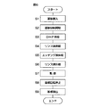
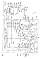
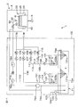
- FIG. 7 is a process diagram for describing an example of substrate processing performed by the substrate processing apparatus. It is a schematic diagram which shows a chemical solution supply unit, a chemical solution recovery unit, a concentration measurement unit, and a dissolved oxygen concentration change unit. It is the schematic diagram which looked at the external appearance of the 1st cooler attached to the 1st rise piping horizontally.
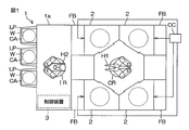
- FIG. 1 is a schematic view of the substrate processing apparatus 1 according to the first embodiment of the present invention viewed from above.
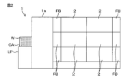
- FIG. 2 is a schematic view of the substrate processing apparatus 1 viewed from the side.
- the substrate processing apparatus 1 is a single-wafer processing apparatus that processes disk-shaped substrates W such as semiconductor wafers one by one.
- the substrate processing apparatus 1 includes a load port LP that holds a carrier CA that contains a substrate W, and a plurality of processes that processes the substrate W transported from the carrier CA on the load port LP with a processing fluid such as a processing liquid or a processing gas.
- the unit 2 includes a carrier robot that carries the substrate W between the carrier CA on the load port LP and the processing unit 2, and a controller 3 that controls the substrate processing apparatus 1.
- the transfer robot includes an indexer robot IR for loading and unloading the substrate W with respect to the carrier CA on the load port LP, and a center robot CR for loading and unloading the substrate W with respect to the plurality of processing units 2.
- the indexer robot IR transfers the substrate W between the load port LP and the center robot CR, and the center robot CR transfers the substrate W between the indexer robot IR and the processing unit 2.
- the center robot CR includes a hand H1 that supports the substrate W, and the indexer robot IR includes a hand H2 that supports the substrate W.
- the substrate processing apparatus 1 includes a plurality of (for example, four) fluid boxes FB that accommodate fluid devices such as valves.
- a chemical liquid cabinet CC that accommodates a chemical liquid tank and the like is arranged outside the outer wall 1 a of the substrate processing apparatus 1.
- the chemical liquid cabinet CC may be arranged beside the outer wall 1a of the substrate processing apparatus 1, or may be arranged below (underground) a clean room in which the substrate processing apparatus 1 is installed.
- the plurality of processing units 2 form a plurality of towers arranged around the center robot CR in a plan view.
- FIG. 1 shows an example in which four towers are formed.
- each tower includes a plurality of (for example, three) processing units 2 stacked one above the other.
- the four fluid boxes FB correspond to four towers, respectively.
- the chemical liquid in the chemical liquid cabinet CC is supplied to all the processing units 2 included in the tower corresponding to the fluid box FB via any of the fluid boxes FB.
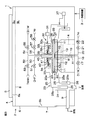
- FIG. 3 is a schematic view of the inside of the processing unit 2 provided in the substrate processing apparatus 1 as viewed horizontally.
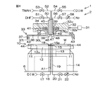
- FIG. 4 is an enlarged view in which a part of FIG. 3 is enlarged.
- FIG. 3 shows a state where the elevating frame 32 and the blocking member 33 are located at the lower position
- FIG. 4 shows a state where the elevating frame 32 and the blocking member 33 are located at the upper position.
- the processing unit 2 includes a box-shaped chamber 4 having an internal space, and a spin chuck 10 that holds a single substrate W horizontally in the chamber 4 and rotates the substrate W around a vertical rotation axis A1 passing through the central portion of the substrate W. And a cylindrical processing cup 23 that surrounds the spin chuck 10 around the rotation axis A1.
- the chamber 4 includes a box-shaped partition wall 6 having a loading / unloading port 6b through which the substrate W passes, and a shutter 7 for opening / closing the loading / unloading port 6b.
- the chamber 4 further includes a rectifying plate 8 arranged below the blower opening 6a that opens on the ceiling surface of the partition wall 6.
- the FFU 5 fan filter unit
- the exhaust duct 9 for discharging the gas in the chamber 4 is connected to the processing cup 23.
- the blower port 6 a is provided at the upper end of the chamber 4, and the exhaust duct 9 is arranged at the lower end of the chamber 4. A part of the exhaust duct 9 is arranged outside the chamber 4.
- the rectifying plate 8 partitions the internal space of the partition wall 6 into an upper space Su above the rectifying plate 8 and a lower space SL below the rectifying plate 8.
- the upper space Su between the ceiling surface of the partition wall 6 and the upper surface of the current plate 8 is a diffusion space in which clean air diffuses.
- the lower space SL between the lower surface of the current plate 8 and the floor surface of the partition wall 6 is a processing space in which the substrate W is processed.
- the spin chuck 10 and the processing cup 23 are arranged in the lower space SL.
- the vertical distance from the floor surface of the partition wall 6 to the lower surface of the flow straightening plate 8 is longer than the vertical distance from the upper surface of the flow straightening plate 8 to the ceiling surface of the partition wall 6.
- the FFU 5 sends clean air to the upper space Su via the air outlet 6a.
- the clean air supplied to the upper space Su hits the current plate 8 and diffuses in the upper space Su.
- the clean air in the upper space Su passes through a plurality of through holes vertically penetrating the straightening vane 8 and flows downward from the entire area of the straightening vane 8.
- the clean air supplied to the lower space SL is sucked into the processing cup 23 and discharged from the lower end of the chamber 4 through the exhaust duct 9. As a result, a uniform downward flow (downflow) of clean air flowing downward from the current plate 8 is formed in the lower space SL.
- the processing of the substrate W is performed in a state where the downflow of clean air is formed.
- the spin chuck 10 includes a disk-shaped spin base 12 held in a horizontal posture, a plurality of chuck pins 11 holding the substrate W in a horizontal posture above the spin base 12, and a central portion of the spin base 12.
- a spin shaft 13 extending downward and a spin motor 14 for rotating the spin base 12 and the plurality of chuck pins 11 by rotating the spin shaft 13 are included.
- the spin chuck 10 is not limited to a sandwich type chuck in which the plurality of chuck pins 11 are brought into contact with the outer peripheral surface of the substrate W, but the back surface (lower surface) of the substrate W, which is a non-device forming surface, is attracted to the upper surface 12u of the spin base 12. It may be a vacuum chuck that holds the substrate W horizontally.
- the spin base 12 includes an upper surface 12u arranged below the substrate W.
- the upper surface 12u of the spin base 12 is parallel to the lower surface of the substrate W.
- the upper surface 12u of the spin base 12 is a facing surface that faces the lower surface of the substrate W.
- the upper surface 12u of the spin base 12 has a ring shape surrounding the rotation axis A1.
- the outer diameter of the upper surface 12u of the spin base 12 is larger than the outer diameter of the substrate W.
- the chuck pin 11 projects upward from the outer peripheral portion of the upper surface 12u of the spin base 12.
- the chuck pin 11 is held by the spin base 12.
- the substrate W is held by the plurality of chuck pins 11 with the lower surface of the substrate W separated from the upper surface 12u of the spin base 12.
- the processing unit 2 includes a lower surface nozzle 15 that discharges the processing liquid toward the central portion of the lower surface of the substrate W.
- the lower surface nozzle 15 includes a nozzle disk portion arranged between the upper surface 12u of the spin base 12 and the lower surface of the substrate W, and a nozzle tubular portion extending downward from the nozzle disk portion.
- the liquid ejection port 15p of the lower surface nozzle 15 is open at the center of the upper surface of the nozzle disk portion. When the substrate W is held by the spin chuck 10, the liquid ejection port 15p of the lower surface nozzle 15 vertically opposes the central portion of the lower surface of the substrate W.
- the substrate processing apparatus 1 includes a lower rinse liquid pipe 16 for guiding the rinse liquid to the lower surface nozzle 15, and a lower rinse liquid valve 17 interposed in the lower rinse liquid pipe 16.
- a lower rinse liquid valve 17 interposed in the lower rinse liquid pipe 16.
- the rinse liquid supplied to the lower surface nozzle 15 is not limited to pure water, but IPA (isopropyl alcohol), carbonated water, electrolytic ionic water, hydrogen water, ozone water, and hydrochloric acid water having a dilution concentration (for example, about 1 to 100 ppm) It may be either.
- the lower rinse liquid valve 17 includes a valve body provided with an internal flow passage through which the liquid flows and an annular valve seat surrounding the internal flow passage, a valve body movable with respect to the valve seat, and a valve. And an actuator that moves the valve body between a closed position in which the body contacts the valve seat and an open position in which the valve body is spaced from the valve seat.
- the actuator may be a pneumatic actuator or an electric actuator, or may be an actuator other than these.
- the control device 3 controls the actuator to open and close the lower rinse liquid valve 17.
- the outer peripheral surface of the lower surface nozzle 15 and the inner peripheral surface of the spin base 12 form a lower tubular passage 19 extending vertically.
- the lower cylindrical passage 19 includes a lower central opening 18 that opens at the central portion of the upper surface 12u of the spin base 12.
- the lower central opening 18 is arranged below the nozzle disk portion of the lower surface nozzle 15.
- the substrate processing apparatus 1 includes a lower gas pipe 20 for guiding an inert gas supplied to the lower central opening 18 via a lower tubular passage 19, a lower gas valve 21 interposed in the lower gas pipe 20, and a lower gas.
- a lower gas flow rate adjusting valve 22 that changes the flow rate of the inert gas supplied from the pipe 20 to the lower tubular passage 19 is provided.
- the inert gas supplied from the lower gas pipe 20 to the lower tubular passage 19 is nitrogen gas.
- Nitrogen gas does not contain oxygen or contains very little oxygen.
- the inert gas is not limited to nitrogen gas, and may be other inert gas such as helium gas or argon gas. These inert gases are gases having an oxygen concentration lower than the oxygen concentration in air (about 21 vol%).
- the nitrogen gas supplied from the lower gas pipe 20 to the lower tubular passage 19 is discharged upward from the lower central opening 18 at a flow rate corresponding to the opening degree of the lower gas flow rate adjusting valve 22. It After that, the nitrogen gas radially flows between the lower surface of the substrate W and the upper surface 12u of the spin base 12 in the horizontal direction. As a result, the space between the substrate W and the spin base 12 is filled with nitrogen gas, and the oxygen concentration in the atmosphere is reduced. The oxygen concentration in the space between the substrate W and the spin base 12 is changed according to the opening degrees of the lower gas valve 21 and the lower gas flow rate adjusting valve 22.
- the processing cup 23 includes a plurality of guards 25 for receiving the liquid discharged outward from the substrate W, a plurality of cups 26 for receiving the liquid guided downward by the plurality of guards 25, a plurality of guards 25 and a plurality of cups. 26 and a cylindrical outer wall member 24 surrounding the same.
- FIG. 3 shows an example in which two guards 25 and two cups 26 are provided.
- the guard 25 includes a cylindrical guard tubular portion 25b surrounding the spin chuck 10 and an annular guard ceiling portion 25a extending obliquely upward from the upper end portion of the guard tubular portion 25b toward the rotation axis A1.
- the plurality of guard ceiling portions 25a are vertically stacked, and the plurality of guard tubular portions 25b are arranged concentrically.
- the plurality of cups 26 are arranged below the plurality of guard tubular portions 25b, respectively. Each of the plurality of cups 26 forms an annular liquid receiving groove that opens upward.
- the processing unit 2 includes a guard lifting unit 27 that lifts and lowers the plurality of guards 25 individually.
- the guard lifting unit 27 positions the guard 25 at any position from the upper position to the lower position.
- the upper position is a position where the upper end 25u of the guard 25 is arranged above the holding position where the substrate W held by the spin chuck 10 is arranged.
- the lower position is a position where the upper end 25u of the guard 25 is arranged below the holding position.
- the annular upper end of the guard ceiling portion 25a corresponds to the upper end 25u of the guard 25.
- the upper end 25u of the guard 25 surrounds the substrate W and the spin base 12 in a plan view.
- the processing liquid When the processing liquid is supplied to the substrate W while the spin chuck 10 is rotating the substrate W, the processing liquid is shaken off from the substrate W.
- the processing liquid When the processing liquid is supplied to the substrate W, the upper end 25u of at least one guard 25 is arranged above the substrate W. Therefore, the processing liquid such as the chemical liquid and the rinse liquid discharged from the substrate W is received by one of the guards 25 and guided to the cup 26 corresponding to the guard 25.
- the processing unit 2 includes an elevating frame 32 arranged above the spin chuck 10, a blocking member 33 suspended from the elevating frame 32, and a central nozzle 45 inserted in the blocking member 33. And a blocking member lifting unit 31 that lifts the blocking member 33 and the central nozzle 45 by lifting the lifting frame 32.
- the elevating frame 32, the blocking member 33, and the central nozzle 45 are arranged below the straightening vane 8.
- the blocking member 33 includes a disc portion 36 arranged above the spin chuck 10 and a tubular portion 37 extending downward from the outer peripheral portion of the disc portion 36.
- the blocking member 33 includes a cup-shaped inner surface that is recessed upward.
- the inner surface of the blocking member 33 includes the lower surface 36L of the disc portion 36 and the inner peripheral surface 37i of the tubular portion 37. Below, the lower surface 36L of the disk portion 36 may be referred to as the lower surface 36L of the blocking member 33.
- the lower surface 36L of the disc portion 36 is a facing surface that faces the upper surface of the substrate W.
- the lower surface 36L of the disc portion 36 is parallel to the upper surface of the substrate W.
- the inner peripheral surface 37i of the tubular portion 37 extends downward from the outer peripheral edge of the lower surface 36L of the disc portion 36.
- the inner diameter of the tubular portion 37 increases as it approaches the lower end of the inner peripheral surface 37i of the tubular portion 37.
- the inner diameter of the lower end of the inner peripheral surface 37i of the tubular portion 37 is larger than the diameter of the substrate W.
- the inner diameter of the lower end of the inner peripheral surface 37i of the tubular portion 37 may be larger than the outer diameter of the spin base 12.
- the lower surface 36L of the disc portion 36 is an annular shape surrounding the rotation axis A1.
- An inner peripheral edge of the lower surface 36L of the disc portion 36 forms an upper central opening 38 that opens at the central portion of the lower surface 36L of the disc portion 36.
- the inner peripheral surface of the blocking member 33 forms a through hole extending upward from the upper central opening 38.
- the through hole of the blocking member 33 vertically penetrates the blocking member 33.
- the central nozzle 45 is inserted into the through hole of the blocking member 33.
- the outer diameter of the lower end of the central nozzle 45 is smaller than the diameter of the upper central opening 38.
- the inner peripheral surface of the blocking member 33 is coaxial with the outer peripheral surface of the central nozzle 45.
- the inner peripheral surface of the blocking member 33 surrounds the outer peripheral surface of the central nozzle 45 at intervals in the radial direction (direction orthogonal to the rotation axis A1).
- the inner peripheral surface of the blocking member 33 and the outer peripheral surface of the central nozzle 45 form an upper cylindrical passage 39 extending vertically.
- the central nozzle 45 projects upward from the elevating frame 32 and the blocking member 33. When the blocking member 33 is suspended from the elevating frame 32, the lower end of the central nozzle 45 is disposed above the lower surface 36L of the disc portion 36.
- a processing liquid such as a chemical liquid or a rinse liquid is discharged downward from the lower end of the central nozzle 45.
- the blocking member 33 includes a cylindrical connecting portion 35 extending upward from the disc portion 36, and an annular flange portion 34 extending outward from the upper end portion of the connecting portion 35.
- the flange portion 34 is arranged above the disc portion 36 and the tubular portion 37 of the blocking member 33.
- the flange portion 34 is parallel to the disc portion 36.
- the outer diameter of the flange portion 34 is smaller than the outer diameter of the tubular portion 37.
- the flange portion 34 is supported by a lower plate 32L of the elevating frame 32, which will be described later.
- the elevating frame 32 includes an upper plate 32u located above the flange portion 34 of the blocking member 33, a side ring 32s that extends downward from the upper plate 32u, and surrounds the flange portion 34, and an inner side from a lower end portion of the side ring 32s. And an annular lower plate 32L that extends downwardly and that is located below the flange portion 34 of the blocking member 33.
- the outer peripheral portion of the flange portion 34 is arranged between the upper plate 32u and the lower plate 32L.
- the outer peripheral portion of the flange portion 34 is vertically movable between the upper plate 32u and the lower plate 32L.
- the elevating frame 32 and the blocking member 33 are positioned to restrict relative movement of the elevating frame 32 and the blocking member 33 in the circumferential direction (direction around the rotation axis A1) in a state where the blocking member 33 is supported by the elevating frame 32.
- It includes a protrusion 41 and a positioning hole 42.
- FIG. 3 shows an example in which a plurality of positioning protrusions 41 are provided in the lower plate 32L and a plurality of positioning holes 42 are provided in the flange portion 34.
- the positioning protrusion 41 may be provided on the flange portion 34, and the positioning hole 42 may be provided on the lower plate 32L.
- the plurality of positioning protrusions 41 are arranged on a circle having a center arranged on the rotation axis A1.
- the plurality of positioning holes 42 are arranged on a circle having a center arranged on the rotation axis A1.
- the plurality of positioning holes 42 are arranged in the circumferential direction with the same regularity as the plurality of positioning protrusions 41.
- the positioning protrusion 41 protruding upward from the upper surface of the lower plate 32L is inserted into the positioning hole 42 extending upward from the lower surface of the flange portion 34. This restricts the movement of the blocking member 33 in the circumferential direction with respect to the elevating frame 32.
- the blocking member 33 includes a plurality of upper support portions 43 protruding downward from the inner surface of the blocking member 33.
- the spin chuck 10 includes a plurality of lower support portions 44 that respectively support the plurality of upper support portions 43.
- the plurality of upper support portions 43 are surrounded by the tubular portion 37 of the blocking member 33.
- the lower end of the upper support portion 43 is arranged above the lower end of the tubular portion 37.
- the radial distance from the rotation axis A1 to the upper support portion 43 is larger than the radius of the substrate W.
- the radial distance from the rotation axis A1 to the lower support portion 44 is larger than the radius of the substrate W.
- the lower support portion 44 projects upward from the upper surface 12u of the spin base 12.
- the lower support portion 44 is arranged outside the chuck pin 11.
- the plurality of upper support portions 43 are arranged on a circle having a center arranged on the rotation axis A1.
- the plurality of lower support portions 44 are arranged on a circle having a center arranged on the rotation axis A1.
- the plurality of lower support portions 44 are arranged in the circumferential direction with the same regularity as the plurality of upper support portions 43.
- the plurality of lower support portions 44 rotate together with the spin base 12 about the rotation axis A1.
- the rotation angle of the spin base 12 is changed by the spin motor 14.
- the plurality of upper support portions 43 respectively overlap the plurality of lower support portions 44 in plan view.
- the blocking member lifting unit 31 is connected to the lifting frame 32.
- the blocking member elevating unit 31 lowers the elevating frame 32 while the flange portion 34 of the blocking member 33 is supported by the lower plate 32L of the elevating frame 32, the blocking member 33 also lowers.
- the blocking member elevating unit 31 lowers the blocking member 33 in a state where the spin base 12 is arranged at a reference rotation angle where the plurality of upper supporting portions 43 overlap with the plurality of lower supporting portions 44 in a plan view, the upper supporting portions 43 are supported.
- the lower end of the portion 43 contacts the upper end of the lower support portion 44.
- the plurality of upper support portions 43 are respectively supported by the plurality of lower support portions 44.
- the blocking member elevating unit 31 positions the elevating frame 32 at any position from the upper position (the position shown in FIG. 4) to the lower position (the position shown in FIG. 3).
- the upper position is a position where the positioning protrusion 41 is inserted into the positioning hole 42 and the flange portion 34 of the blocking member 33 is in contact with the lower plate 32L of the elevating frame 32. That is, the upper position is the position where the blocking member 33 is suspended from the elevating frame 32.
- the lower position is a position where the lower plate 32L is separated from the flange portion 34 and the positioning protrusion 41 is pulled out from the positioning hole 42. That is, the lower position is a position where the connection between the elevating frame 32 and the blocking member 33 is released and the blocking member 33 does not contact any part of the elevating frame 32.
- the lower end of the tubular portion 37 of the blocking member 33 is arranged below the lower surface of the substrate W, and the upper surface of the substrate W and the lower surface 36L of the blocking member 33 are separated from each other.
- the space therebetween is surrounded by the tubular portion 37 of the blocking member 33. Therefore, the space between the upper surface of the substrate W and the lower surface 36L of the blocking member 33 is shielded not only from the atmosphere above the blocking member 33 but also from the atmosphere around the blocking member 33.
- the degree of sealing of the space between the upper surface of the substrate W and the lower surface 36L of the blocking member 33 can be increased.
- the blocking member 33 does not collide with the elevating frame 32 even if the blocking member 33 is rotated around the rotation axis A1 with respect to the elevating frame 32.
- the upper support part 43 of the blocking member 33 is supported by the lower support part 44 of the spin chuck 10, the upper support part 43 and the lower support part 44 mesh with each other, and the relative positions of the upper support part 43 and the lower support part 44 in the circumferential direction. Movement is restricted.
- the spin motor 14 rotates in this state, the torque of the spin motor 14 is transmitted to the blocking member 33 via the upper support portion 43 and the lower support portion 44.
- the blocking member 33 rotates in the same direction as the spin base 12 at the same speed while the elevating frame 32 and the central nozzle 45 are stationary.
- the central nozzle 45 includes a plurality of liquid discharge ports that discharge liquid and a gas discharge port that discharges gas.
- the plurality of liquid discharge ports include a first chemical liquid discharge port 46 that discharges the first chemical liquid, a second chemical liquid discharge port 47 that discharges the second chemical liquid, and an upper rinse liquid discharge port 48 that discharges the rinse liquid.
- the gas discharge port is the upper gas discharge port 49 that discharges the inert gas.
- the first chemical liquid discharge port 46, the second chemical liquid discharge port 47, and the upper rinse liquid discharge port 48 are open at the lower end of the center nozzle 45.
- the upper gas discharge port 49 opens on the outer peripheral surface of the central nozzle 45.
- the first chemical liquid and the second chemical liquid are, for example, sulfuric acid, nitric acid, hydrochloric acid, hydrofluoric acid, phosphoric acid, acetic acid, aqueous ammonia, hydrogen peroxide solution, organic acids (eg citric acid, oxalic acid, etc.), organic alkalis (eg TMAH ( Tetramethylammoniumhydroxide), an inorganic alkali (eg, NaOH (sodium hydroxide)), a surfactant, and a solution containing at least one of corrosion inhibitors: sulfuric acid, nitric acid, hydrochloric acid, hydrofluoric acid, phosphoric acid, acetic acid.
- Ammonia water, hydrogen peroxide water, citric acid, oxalic acid, inorganic alkali and TMAH are etching liquids.
- the first chemical liquid and the second chemical liquid may be the same chemical liquid or different chemical liquids from each other.
- FIG. 3 shows an example in which the first chemical liquid is DHF (dilute hydrofluoric acid) and the second chemical liquid is TMAH.
- FIG. 3 shows an example in which the rinse liquid supplied to the central nozzle 45 is pure water and the inert gas supplied to the central nozzle 45 is nitrogen gas.
- TMAH is an aqueous solution of TMAH, but hereinafter, an aqueous solution of TMAH is referred to as TMAH unless otherwise specified.
- the dissolved oxygen concentration of TMAH is adjusted in advance.
- the dissolved oxygen concentration of DHF is also adjusted in advance.
- the rinse liquid supplied to the central nozzle 45 may be a rinse liquid other than pure water.
- the inert gas supplied to the central nozzle 45 may be an inert gas other than nitrogen gas.
- the substrate processing apparatus 1 guides a first chemical liquid to the central nozzle 45, a first chemical liquid pipe 50, a first chemical liquid valve 51 interposed in the first chemical liquid pipe 50, and a second chemical liquid to the central nozzle 45.
- An upper rinse liquid valve 55 is provided.
- the substrate processing apparatus 1 further includes an upper gas pipe 56 for guiding the gas to the central nozzle 45, an upper gas valve 57 interposed in the upper gas pipe 56, and a gas supplied from the upper gas pipe 56 to the central nozzle 45.
- An upper gas flow rate adjusting valve 58 for changing the flow rate is provided.
- the first chemical liquid valve 51 When the first chemical liquid valve 51 is opened, the first chemical liquid is supplied to the central nozzle 45 and is discharged downward from the first chemical liquid discharge port 46 that opens at the lower end of the central nozzle 45.
- the second chemical liquid valve 53 When the second chemical liquid valve 53 is opened, the second chemical liquid is supplied to the central nozzle 45 and is discharged downward from the second chemical liquid discharge port 47 that opens at the lower end of the central nozzle 45.
- the upper rinse liquid valve 55 is opened, the rinse liquid is supplied to the central nozzle 45 and is discharged downward from the upper rinse liquid discharge port 48 that opens at the lower end of the central nozzle 45.
- the chemical liquid or the rinse liquid is supplied to the upper surface of the substrate W.
- the nitrogen gas guided by the upper gas pipe 56 is supplied to the central nozzle 45 at a flow rate corresponding to the opening degree of the upper gas flow rate adjusting valve 58, and is opened on the outer peripheral surface of the central nozzle 45.
- the gas is discharged obliquely downward from the upper gas discharge port 49.
- the nitrogen gas flows downward in the upper tubular passage 39 while flowing in the upper tubular passage 39 in the circumferential direction.
- the nitrogen gas reaching the lower end of the upper tubular passage 39 flows out downward from the lower end of the upper tubular passage 39. After that, the nitrogen gas radially flows in all directions in the space between the upper surface of the substrate W and the lower surface 36L of the blocking member 33.
- the space between the substrate W and the blocking member 33 is filled with nitrogen gas, and the oxygen concentration in the atmosphere is reduced.
- the oxygen concentration in the space between the substrate W and the blocking member 33 is changed according to the opening degrees of the upper gas valve 57 and the upper gas flow rate adjusting valve 58.
- FIG. 5 is a block diagram showing the hardware of the control device 3.
- the control device 3 is a computer including a computer main body 61 and a peripheral device 64 connected to the computer main body 61.
- the computer main body 61 includes a CPU 62 (central processing unit) that executes various instructions and a main storage device 63 that stores information.
- the peripheral device 64 includes an auxiliary storage device 65 that stores information such as the program P, a reading device 66 that reads information from the removable medium M, and a communication device 67 that communicates with other devices such as a host computer.
- the control device 3 is connected to the input device 68 and the display device 69.
- the input device 68 is operated when an operator such as a user or a person in charge of maintenance inputs information to the substrate processing apparatus 1.
- the information is displayed on the screen of the display device 69.
- the input device 68 may be any one of a keyboard, a pointing device, and a touch panel, or may be a device other than these.
- a touch panel display that also serves as the input device 68 and the display device 69 may be provided in the substrate processing apparatus 1.
- the CPU 62 executes the program P stored in the auxiliary storage device 65.
- the program P in the auxiliary storage device 65 may be installed in the control device 3 in advance, or may be sent from the removable medium M to the auxiliary storage device 65 through the reading device 66, It may be sent from an external device such as a host computer to the auxiliary storage device 65 through the communication device 67.
- the auxiliary storage device 65 and the removable medium M are non-volatile memories that retain the memory even when power is not supplied.
- the auxiliary storage device 65 is, for example, a magnetic storage device such as a hard disk drive.
- the removable medium M is, for example, an optical disk such as a compact disk or a semiconductor memory such as a memory card.
- the removable medium M is an example of a computer-readable recording medium in which the program P is recorded.
- the upper gas valve 57 and the lower gas valve 21 are opened, and the upper central opening 38 of the blocking member 33 and the lower central opening 18 of the spin base 12 start discharging nitrogen gas.
- the blocking member elevating unit 31 lowers the elevating frame 32 from the upper position to the lower position, and the guard elevating unit 27 raises one of the guards 25 from the lower position to the upper position.
- the spin base 12 is held at the reference rotation angle at which the plurality of upper support portions 43 overlap the plurality of lower support portions 44 in plan view. Therefore, the upper support portion 43 of the blocking member 33 is supported by the lower support portion 44 of the spin base 12, and the blocking member 33 separates from the elevating frame 32.
- the spin motor 14 is driven and the rotation of the substrate W is started (step S2 in FIG. 6).
- the first chemical liquid valve 51 is opened with the blocking member 33 positioned at the lower position, and the central nozzle 45 starts discharging DHF.
- the DHF discharged from the central nozzle 45 after landing on the central portion of the upper surface of the substrate W, flows outward along the upper surface of the rotating substrate W. As a result, a DHF liquid film covering the entire upper surface of the substrate W is formed, and DHF is supplied to the entire upper surface of the substrate W.
- the first chemical liquid valve 51 is closed and the discharge of DHF is stopped.
- the upper rinse liquid valve 55 is opened with the blocking member 33 positioned at the lower position, and the central nozzle 45 starts discharging pure water.
- the pure water that has landed on the central portion of the upper surface of the substrate W flows outward along the upper surface of the rotating substrate W.
- the DHF on the substrate W is washed away by the pure water discharged from the central nozzle 45.
- a pure water liquid film covering the entire upper surface of the substrate W is formed.
- a second chemical liquid supply step of supplying TMAH, which is an example of the second chemical liquid, to the upper surface of the substrate W is performed (step S5 in FIG. 6).
- the second chemical liquid valve 53 is opened with the blocking member 33 positioned at the lower position, and the central nozzle 45 starts discharging TMAH.
- the guard elevating unit 27 may move at least one guard 25 vertically in order to switch the guard 25 that receives the liquid discharged from the substrate W.
- the TMAH that has landed on the central portion of the upper surface of the substrate W flows outward along the upper surface of the rotating substrate W. Pure water on the substrate W is replaced with TMAH discharged from the central nozzle 45. As a result, a TMAH liquid film covering the entire upper surface of the substrate W is formed.
- the second chemical liquid valve 53 is closed and the discharge of TMAH is stopped.
- the spin motor 14 accelerates the substrate W in the rotation direction while the blocking member 33 is in the lower position, and the substrate W in the period from the first chemical liquid supply process to the second rinse liquid supply process is increased.
- the substrate W is rotated at a high rotation speed (for example, several thousand rpm) higher than the rotation speed.
- a high rotation speed for example, several thousand rpm
- the spin motor 14 stops rotating.
- the spin motor 14 stops the spin base 12 at the reference rotation angle.
- the rotation of the substrate W is stopped (step S8 in FIG. 6).
- the chemical liquid supply unit 71 measures the temperature of the chemical liquid whose temperature is adjusted by the first temperature controller 77A that changes the temperature of the chemical liquid in the first supply tank 72A by heating or cooling the chemical liquid, and the temperature of the chemical liquid adjusted by the first temperature controller 77A.
- the first thermometer 78A may be included.
- the first temperature controller 77A and the first thermometer 78A are installed in the first circulation pipe 74A. The temperature of the first temperature controller 77A is changed based on the measurement value of the first thermometer 78A. As a result, the temperature of the chemical liquid in the first supply tank 72A is maintained at the set temperature.
- the first temperature controller 77A is a heater that heats the liquid at a temperature higher than room temperature (for example, 20 to 30 ° C.), and the first thermometer 78A measures the temperature of the chemical liquid in the first circulation pipe 74A.
- the first temperature controller 77A may be a cooler that cools the liquid at a temperature lower than room temperature, or may have both heating and cooling functions.
- the first temperature controller 77A may be arranged in the first supply tank 72A.
- the first thermometer 78A may measure the temperature of the chemical liquid in the first supply tank 72A.
- the chemical solution in the upstream recovery tank 84 is sent from the upstream recovery tank 84 to the intermediate pipe 87 by the upstream pump 88 and flows into the downstream recovery tank 89.
- the chemical liquid in the upstream recovery tank 84 is recovered in the downstream recovery tank 89 through the intermediate pipe 87.
- the chemical liquid in the upstream recovery tank 84 is sent to the intermediate pipe 87 by the upstream pump 88, air flows into the upstream recovery tank 84 via the breather pipe 86.
- the downstream recovery tank 89 is connected to the upstream end of the downstream pipe 90.
- the downstream end of the downstream pipe 90 is connected to the first supply tank 72A.
- the chemical liquid recovery unit 81 includes a downstream valve 93 that opens and closes the inside of the downstream pipe 90.
- the chemical liquid recovery unit 81 further includes a downstream pump 91 that sends the chemical liquid in the downstream recovery tank 89 to the first supply tank 72A through the downstream pipe 90, a downstream filter 92 that removes foreign matters from the chemical liquid that flows in the downstream pipe 90, and a downstream.
- a return pipe 94 for guiding the chemical liquid in the pipe 90 to the downstream recovery tank 89 is included.
- the gas outlet 123p of the first upstream gas supply pipe 123 is arranged in the chemical liquid in the first gas generation tank 122.
- the low oxygen gas forms many bubbles in the chemical liquid in the first gas generation tank 122.
- the low oxygen gas floats in the chemical liquid to the liquid surface of the chemical liquid and mixes with the gas on the liquid surface of the chemical liquid.
- the chemical vapor and mist are dispersed in the low oxygen gas.
- the adjusted gas containing the low oxygen gas and the chemical liquid is generated in the first gas generation tank 122.
- the gas dissolving apparatus 101 includes a second gas generation tank 132 that stores a chemical solution (TMAH in this example), a second upstream gas supply pipe 133 that supplies low oxygen gas into the second gas generation tank 132, and a second The second downstream gas supply pipe 131 for supplying the regulated gas generated in the gas generation tank 132 to the downstream recovery tank 89 is included.
- the gas dissolving device 101 may include a second check valve 134 interposed in the second upstream gas supply pipe 133. In this case, the reverse flow of gas in the second upstream gas supply pipe 133 (the flow of gas in the direction away from the gas discharge port 133p of the second upstream gas supply pipe 133) is prevented by the second check valve 134.
- the gas discharge port 133p of the second upstream gas supply pipe 133 is arranged in the chemical liquid in the second gas generation tank 132.
- the low oxygen gas forms a large number of bubbles in the chemical liquid in the second gas generation tank 132.
- the low oxygen gas floats in the chemical liquid to the liquid surface of the chemical liquid and mixes with the gas on the liquid surface of the chemical liquid.
- the chemical vapor and mist are dispersed in the low oxygen gas.
- the adjusted gas containing the low oxygen gas and the chemical liquid is generated in the second gas generation tank 132.
- the adjusted gas in the second gas generation tank 132 flows into the upstream end of the second downstream gas supply pipe 131 provided with a gas inlet.
- the upstream end of the second downstream gas supply pipe 131 is connected to the second gas generation tank 132.
- the upstream end of the second downstream gas supply pipe 131 is arranged above the liquid surface of the chemical liquid in the second gas generation tank 132. If the gas in the second gas generation tank 132 flows into the second downstream gas supply pipe 131, even if the upstream end of the second downstream gas supply pipe 131 is arranged in the second gas generation tank 132. It may be arranged on the surface of the second gas generation tank 132.
- the gas discharge port 131p of the second downstream gas supply pipe 131 is arranged in the chemical solution in the downstream recovery tank 89. If the adjusted gas discharged from the gas discharge port 131p of the second downstream gas supply pipe 131 is supplied into the downstream recovery tank 89, the gas discharge port 131p of the second downstream gas supply pipe 131 will be connected to the downstream recovery tank 89. It may be arranged above the liquid surface of the drug solution inside.
- the adjustment gas discharged from the gas discharge port 131p of the second downstream gas supply pipe 131 forms a large number of bubbles in the chemical liquid in the downstream recovery tank 89. After that, the adjusted gas floats in the chemical liquid to the liquid surface of the chemical liquid and mixes with the gas on the liquid surface of the chemical liquid.
- a part of the adjusted gas supplied into the downstream recovery tank 89 dissolves in the chemical solution in the downstream recovery tank 89.
- Dissolved gas such as dissolved oxygen is discharged from the chemical liquid in the downstream recovery tank 89 by dissolving the adjusted gas.
- the adjustment gas is a gas whose main component is a low oxygen gas whose oxygen concentration is lower than that of air. Therefore, the dissolved oxygen concentration of the chemical solution in the downstream recovery tank 89 decreases due to the dissolution of the adjusted gas.
- the chemical liquid having a low dissolved oxygen concentration is supplied from the downstream recovery tank 89 to the first supply tank 72A.
- the first gas generation tank 122 and the first upstream gas supply pipe 123 are included in the first gas generator that generates the first adjusted gas.
- the second gas generation tank 132 and the second upstream gas supply pipe 133 are included in the second gas generator that generates the second adjusted gas.
- the second gas generation tank 132 corresponds to the preliminary gas generation tank. Therefore, the chemical liquid in the second gas generation tank 132 corresponds to the preconditioned liquid, and the regulated gas generated in the second gas generation tank 132 corresponds to the preconditioned gas.
- the gas dissolving apparatus 101 includes a second inert gas pipe 110 that guides an inert gas to the second upstream gas supply pipe 133, and an inert gas from the second inert gas pipe 110 to the second upstream gas supply pipe 133.
- a second inert gas valve 111 that opens and closes between an open state in which gas flows and a closed state in which inert gas is blocked by the second inert gas pipe 110, and a second upstream gas supply pipe from the second inert gas pipe 110.
- a second inert gas flow rate adjusting valve 112 for changing the flow rate of the inert gas supplied to 133.
- the gas dissolving device 101 includes, in addition to the first inert gas pipe 103 and the like, a first oxygen-containing gas pipe 106 that guides an oxygen-containing gas containing oxygen such as clean air to the first upstream gas supply pipe 123; A first oxygen-containing gas valve 107 that opens and closes between an open state in which the oxygen-containing gas flows from the oxygen-containing gas pipe 106 to the first upstream gas supply pipe 123 and a closed state in which the oxygen-containing gas is dammed by the first oxygen-containing gas pipe 106. And a first oxygen-containing gas flow rate adjusting valve 108 that changes the flow rate of the oxygen-containing gas supplied from the first oxygen-containing gas pipe 106 to the first upstream gas supply pipe 123.
- the gas dissolving apparatus 101 includes, in addition to the second inert gas pipe 110 and the like, a second oxygen-containing gas pipe 113 for guiding an oxygen-containing gas containing oxygen such as clean air to the second upstream gas supply pipe 133.
- Second oxygen that is opened and closed between an open state in which the oxygen-containing gas flows from the second oxygen-containing gas pipe 113 to the second upstream gas supply pipe 133 and a closed state in which the oxygen-containing gas is dammed by the second oxygen-containing gas pipe 113. It may include a containing gas valve 114 and a second oxygen containing gas flow rate adjusting valve 115 for changing the flow rate of the oxygen containing gas supplied from the second oxygen containing gas pipe 113 to the second upstream gas supply pipe 133.
- the second gas generation tank 132 is a sealed tank.
- nitrogen gas is supplied from the second inert gas pipe 110 to the second upstream gas supply pipe 133 at a flow rate corresponding to the opening degree of the second inert gas flow rate adjusting valve 112.
- the second oxygen-containing gas valve 114 is opened, air is supplied from the second oxygen-containing gas pipe 113 to the second upstream gas supply pipe 133 at a flow rate corresponding to the opening degree of the second oxygen-containing gas flow rate adjusting valve 115. .. Therefore, by adjusting the openings of the second inert gas flow rate adjusting valve 112 and the second oxygen-containing gas flow rate adjusting valve 115, the flow rate of the adjusting gas supplied into the downstream recovery tank 89 can be precisely controlled.
- the gas dissolving device 101 includes a first gas discharge pipe 125 that discharges the gas in the first supply tank 72A.
- the upstream end of the first gas discharge pipe 125 provided with a gas inlet is connected to the first supply tank 72A.
- the downstream end of the first gas discharge pipe 125 provided with a gas outlet is arranged in a space maintained at atmospheric pressure. Therefore, the atmospheric pressure in the first supply tank 72A is maintained at or near atmospheric pressure.
- the gas dissolving device 101 may include a relief valve that discharges the gas in the first supply tank 72A to the first gas discharge pipe 125 only when the atmospheric pressure in the first supply tank 72A is equal to or higher than the set pressure.
- the first gas discharge pipe 125 includes a first rising pipe 126 extending upward from the first supply tank 72A.
- the second gas discharge pipe 135 includes a second ascending pipe 136 extending upward from the downstream recovery tank 89.
- the first rising pipe 126 may be vertical or may be inclined with respect to the horizontal plane. Further, the first rising pipe 126 may have any of a linear shape, a broken line shape, and a curved shape. The same applies to the second rising pipe 136.
- the upstream end of the first ascending pipe 126 corresponds to the uppermost end of the first ascending pipe 126.
- the upstream end of the second ascending pipe 136 corresponds to the uppermost end of the second ascending pipe 136.
- FIG. 8A is a schematic diagram in which the outer appearance of the first cooler 127 attached to the first ascending pipe 126 is viewed horizontally.
- FIG. 8B is a schematic diagram showing a vertical cross section of the first rising pipe 126 and the first supply tank 72A.
- the second cooler 137 has the same configuration as the first cooler 127.
- the positional relationship between the second cooler 137 and the second rising pipe 136 is the same as the positional relationship between the first cooler 127 and the first rising pipe 126. Therefore, hereinafter, the first cooler 127 will be described and the description of the second cooler 137 will be omitted.
- the first cooler 127 includes a first cooling pipe 128 that guides a cooling fluid having a temperature lower than room temperature.
- the first cooling pipe 128 is spirally wound around the first rising pipe 126.
- the first cooling pipe 128 is in contact with the outer peripheral surface of the first rising pipe 126.
- the cooling fluid constantly flows in the first rising pipe 126, and cools the first rising pipe 126 via the first cooling pipe 128.
- the cooling fluid may be a cooling liquid such as cooling water or a cooling gas.
- Exhaust gas discharged from the first supply tank 72A to the first ascending pipe 126 contains not only low oxygen gas but also vapor of chemical liquid and mist.
- the vapor of the chemical solution changes into droplets or the droplets contained in the mist of the chemical solution become large. Therefore, as shown in FIG. 8B, the liquid droplets of the chemical liquid adhere to the inner peripheral surface of the first rising pipe 126.
- the second ascending pipe 136 liquid drops of the chemical liquid adhere to the inner peripheral surface of the second ascending pipe 136.
- the first ascending pipe 126 is an example of a first recycling pipe that returns the liquid drops of the chemical liquid to the first supply tank 72A.
- the second ascending pipe 136 is an example of a second recycle pipe for returning the liquid drops of the chemical liquid to the downstream recovery tank 89.
- FIG. 8B when the liquid drop of the chemical liquid becomes large to some extent, it flows toward the first supply tank 72A along the inner peripheral surface of the first rising pipe 126 by its own weight, and drops into the chemical liquid in the first supply tank 72A. To do.
- the liquid droplets of the chemical liquid become large to some extent, they drop into the chemical liquid in the downstream recovery tank 89. As a result, it is possible to reduce the reduction amount of the chemical liquid in the first supply tank 72A and the downstream recovery tank 89.
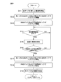
- FIG. 9 is a flowchart showing an example of a flow from supplying a new chemical liquid to the first supply tank 72A to discharging the chemical liquid in the first supply tank 72A.
- the operations described below are executed by the control device 3 controlling the substrate processing apparatus 1.
- the control device 3 is programmed to execute the following operations and the like. In the following, reference is made to FIGS. 7 and 9.
- the chemical solution (TMAH which is an example of the second chemical solution) whose dissolved oxygen concentration is not adjusted is the first supply tank 72A and the upstream recovery tank. It is supplied to 84, the 1st gas production tank 122, and the 2nd gas production tank 132 (Step S11 of Drawing 9).
- the control device 3 opens the first inert gas valve 104 and starts the supply of nitrogen gas to the first gas generation tank 122. Similarly, the control device 3 opens the second inert gas valve 111 and starts the supply of nitrogen gas to the second gas generation tank 132. Thereby, the bubbling of the chemical liquid is started in the first gas generation tank 122 and the second gas generation tank 132. Along with that, the generation of the adjusted gas containing the nitrogen gas and the chemical liquid is started in the first gas generation tank 122 and the second gas generation tank 132 (step S12 in FIG. 9).
- the adjusted gas generated in the first gas generation tank 122 is supplied to the first supply tank 72A.
- the adjusted gas generated in the second gas generation tank 132 is supplied to the downstream recovery tank 89. Therefore, when the supply of the nitrogen gas to the first gas generation tank 122 and the second gas generation tank 132 is started, the supply of the adjusted gas to the first supply tank 72A and the downstream recovery tank 89 is started. Thereby, the bubbling of the chemical liquid is started in the first supply tank 72A and the downstream recovery tank 89 (step S13 in FIG. 9).
- the control device 3 determines that the dissolved oxygen concentration of the chemical solution in the first supply tank 72A is in the final concentration range based on the measurement value of the first oxygen concentration meter 96. It is confirmed whether or not it is within (step S14 of FIG. 9).
- the control device 3 When the dissolved oxygen concentration of the chemical liquid in the first supply tank 72A is not within the final concentration range (No in step S14 in FIG. 9), the control device 3 again stores the first supply tank 72A in the first supply tank 72A after a predetermined time has elapsed. Check whether the dissolved oxygen concentration of the chemical solution is within the final concentration range. Before confirming the dissolved oxygen concentration of the chemical liquid again, the control device 3 changes the flow rate of the nitrogen gas supplied to the first gas generation tank 122 or changes the mixed gas of nitrogen gas and air to the first gas generation tank 122. It may be supplied to.
- the control device 3 opens the second chemical liquid valve 53 to start the first supply tank 72A.
- the supply of the chemical liquid to the central nozzle 45 is started (step S15 in FIG. 9).
- the control device 3 closes the second chemical liquid valve 53 and stops the supply of the chemical liquid to the central nozzle 45.
- the second chemical liquid supply step of supplying TMAH, which is an example of the second chemical liquid, to the upper surface of the substrate W is performed (step S5 in FIG. 6).
- the chemical liquid discharged from the substrate W is supplied to the upstream recovery tank 84 via the guard 25, the cup 26, and the upstream pipe 82.
- the chemical liquid in the upstream recovery tank 84 is supplied to the downstream recovery tank 89 through the intermediate pipe 87.
- the chemical liquid discharged from the substrate W is recovered in the downstream recovery tank 89, and the dissolved oxygen concentration is adjusted in the downstream recovery tank 89.
- the chemical liquid in the downstream recovery tank 89 is supplied to the first supply tank 72A as needed.
- the control device 3 determines whether or not the chemical liquid in the first supply tank 72A should be replaced with a new chemical liquid (step S16 in FIG. 9). Whether or not the chemical solution is replaced may be determined based on at least one of the usage time of the chemical solution and the number of processed substrates W, or may be determined based on other criteria. Alternatively, the chemical liquid in the first supply tank 72A may be exchanged when the user of the substrate processing apparatus 1 inputs a chemical liquid exchange command to the input device 68 (see FIG. 5).
- the control device 3 When it is not necessary to replace the chemical liquid in the first supply tank 72A with a new chemical liquid (No in step S16 of FIG. 9), the control device 3 again determines that the dissolved oxygen concentration of the chemical liquid in the first supply tank 72A is the final value. It is confirmed whether or not it is within the concentration range (step S14 in FIG. 9). If the dissolved oxygen concentration of the chemical liquid in the first supply tank 72A is within the final concentration range (Yes in step S14 of FIG. 9), the control device 3 opens the second chemical liquid valve 53 to start the first supply tank 72A. The supply of the chemical liquid to the central nozzle 45 is started (step S16 in FIG. 9). As a result, TMAH, which is an example of the second chemical liquid, is supplied to another substrate W.
- TMAH which is an example of the second chemical liquid
- the control device 3 closes the first inert gas valve 104, and the nitrogen gas to the first gas generation tank 122 is closed. Stop the gas supply. Similarly, the control device 3 closes the second inert gas valve 111 to stop the supply of the nitrogen gas to the second gas generation tank 132.
- the control device 3 also controls the opened valve (at least one of the first oxygen-containing gas valve 107 and the second oxygen-containing gas valve 114). close.
- step S17 in FIG. 9 the bubbling of the chemical liquid in the first gas generation tank 122 and the second gas generation tank 132 is stopped. Therefore, the production of the adjusted gas in the first gas production tank 122 and the second gas production tank 132 is stopped.
- the chemical solution in the first gas generation tank 122 and the second gas generation tank 132 is discharged (see FIG. 9). Step S19). Similarly, the chemical liquid in the first supply tank 72A and the downstream recovery tank 89 is discharged (step S19 in FIG. 9). After that, the chemical liquid whose dissolved oxygen concentration is not adjusted is again supplied to the first supply tank 72A, the upstream recovery tank 84, the first gas generation tank 122, and the second gas generation tank 132 (step S11 in FIG. 9). .. As a result, the existing drug solution is replaced with a new drug solution.
- the first supply tank 72A is supplied with not only the low oxygen gas but also the adjusted gas containing a trace amount of the chemical liquid.
- the exhaust gas exhausted from the first supply tank 72A to the first gas exhaust pipe 125 also contains a small amount of the chemical liquid.
- the chemical liquid contained in the adjusted gas dissolves in the chemical liquid in the first supply tank 72A.
- the concentration of the chemical liquid in the adjusted gas is equal to or approximately the same as the concentration of the chemical liquid in the exhaust gas. Therefore, the dissolved oxygen concentration of the chemical liquid in the first supply tank 72A can be adjusted while suppressing the decrease of the chemical liquid in the first supply tank 72A.
- the downstream recovery tank 89 is supplied with not only a low oxygen gas but also a regulated gas containing a trace amount of the chemical liquid.
- the exhaust gas discharged from the downstream recovery tank 89 to the second gas exhaust pipe 135 also contains a small amount of the chemical liquid.
- the chemical liquid contained in the adjusted gas dissolves in the chemical liquid in the downstream recovery tank 89.
- the concentration of the chemical liquid in the adjusted gas is equal to or approximately the same as the concentration of the chemical liquid in the exhaust gas. Therefore, the dissolved oxygen concentration of the chemical liquid in the downstream recovery tank 89 can be adjusted while suppressing the decrease of the chemical liquid in the downstream recovery tank 89.
- the chemical liquid in the first gas generation tank 122 will gradually decrease.
- the amount of the new chemical liquid supplied to the first gas generation tank 122 decreases between the time when the new chemical liquid is supplied to the first supply tank 72A and the use of this chemical liquid is stopped. It is preferable that the amount is larger than the amount of the drug solution. In this case, it is not necessary to replenish the first gas generation tank 122 with a new chemical solution between the time when the new chemical solution is supplied to the first supply tank 72A and the use of this chemical solution is stopped.
- the chemical liquid in the second gas generation tank 132 gradually decreases.
- the amount of the new chemical liquid supplied to the second gas generation tank 132 decreases between the time when the new chemical liquid is supplied to the downstream recovery tank 89 and the use of this chemical liquid is stopped. It is preferable that the amount is larger than the amount. In this case, it is not necessary to replenish the second gas generation tank 132 with a new chemical solution between the time when the new chemical solution is supplied to the downstream recovery tank 89 and the use of this chemical solution is stopped.
- the low oxygen gas having the oxygen concentration lower than the oxygen concentration in the air is supplied into the first gas generation tank 122.
- the first gas generation tank 122 stores a chemical liquid corresponding to the first liquid.
- the low oxygen gas is dispersed in the chemical liquid in the first gas generation tank 122 to form a large number of bubbles.
- the low oxygen gas floats in the chemical liquid to the liquid surface of the chemical liquid and mixes with the gas on the liquid surface of the chemical liquid.
- the vapor and mist of the chemical solution are dispersed in the low oxygen gas. Thereby, the adjusted gas containing the low oxygen gas and the chemical liquid is generated.
- the adjusted gas is supplied to the first supply tank 72A that stores the chemical liquid corresponding to the first processing liquid, and is dissolved in the chemical liquid in the first supply tank 72A.
- the adjusted gas contains low oxygen gas. Therefore, by dissolving the adjusted gas, oxygen in the chemical liquid is discharged, and the dissolved oxygen concentration of the chemical liquid decreases. As a result, the dissolved oxygen concentration of the chemical liquid in the first supply tank 72A is adjusted.
- TMAH anhydrous
- water H 2 O
- low oxygen gas containing no chemical liquid is supplied into the first gas generation tank 122.
- the low oxygen gas forms a large number of bubbles in the chemical liquid in the first gas generation tank 122 and floats in the chemical liquid to the liquid surface of the chemical liquid.
- a regulated gas having a high concentration of the chemical liquid for example, a regulated gas having a concentration of the chemical liquid at or near the saturated concentration
- the adjustment gas having a high concentration of the chemical liquid is supplied to the first supply tank 72A.
- the reduction amount of the chemical liquid in the first supply tank 72A can be effectively reduced.
- the chemical liquid is stored not only in the first supply tank 72A but also in the first gas generation tank 122. Therefore, the adjusted gas containing the chemical liquid is generated in the first gas generation tank 122 and supplied to the first supply tank 72A. Even if the liquid component of the adjusted gas dissolves in the chemical liquid, the concentration of the chemical liquid in the first supply tank 72A does not change or hardly changes. Accordingly, it is possible to suppress the change in the concentration of the chemical liquid in the first supply tank 72A.
- the chemical liquid supplied to the substrate W from the first supply tank 72A is recovered in the first supply tank 72A via the downstream recovery tank 89.
- the dissolved oxygen concentration of the chemical liquid supplied to the substrate W has changed. Therefore, before the chemical solution is collected in the first supply tank 72A, the adjusted gas containing the low oxygen gas is dissolved in the chemical solution in the downstream recovery tank 89. Thereby, the dissolved oxygen concentration of the chemical liquid in the downstream recovery tank 89 can be brought close to the dissolved oxygen concentration of the chemical liquid in the first supply tank 72A.
- the regulated gas contains not only low oxygen gas but also chemical liquid. Therefore, the dissolved oxygen concentration of the chemical liquid in the downstream recovery tank 89 can be adjusted while suppressing the decrease of the chemical liquid in the downstream recovery tank 89.
- the gas in the first supply tank 72A is discharged from the first supply tank 72A while the adjusted gas is allowed to flow into the first supply tank 72A.
- the exhaust gas discharged from the first supply tank 72A contains vapor of chemical liquid and mist.
- the exhaust gas is cooled in the first ascending pipe 126 extending upward from the first supply tank 72A.
- a part of the chemical liquid contained in the exhaust gas adheres to the inner peripheral surface of the first rising pipe 126.
- the droplet of the chemical liquid becomes large to some extent, the droplet of the chemical liquid flows toward the first supply tank 72A along the inner peripheral surface of the first rising pipe 126 by its own weight, and drops into the chemical liquid in the first supply tank 72A. ..
- the chemical liquid contained in the exhaust gas can be returned to the first supply tank 72A.
- the gas in the downstream recovery tank 89 is discharged from the downstream recovery tank 89 while allowing the adjusted gas to flow into the downstream recovery tank 89.
- the exhaust gas discharged from the downstream recovery tank 89 contains chemical vapor and mist.
- the exhaust gas is cooled in the second ascending pipe 136 extending upward from the downstream recovery tank 89.
- a part of the chemical liquid contained in the exhaust gas adheres to the inner peripheral surface of the second ascending pipe 136.
- the liquid droplets of the chemical liquid become large to some extent, the liquid droplets of the chemical liquid flow toward the downstream recovery tank 89 along the inner peripheral surface of the second ascending pipe 136 by their own weight, and fall into the chemical liquid in the downstream recovery tank 89.
- the chemical liquid contained in the exhaust gas can be returned to the downstream recovery tank 89.
- Second Embodiment Next, a second embodiment will be described.
- the main difference between the second embodiment and the first embodiment is that a plurality of supply tanks for storing the processing liquid supplied to the substrate W are provided, and the processing liquid in these supply tanks is applied to the substrate W. It is to be mixed before being supplied.
- FIG. 10 is a schematic diagram showing a chemical liquid supply unit 71 and a gas dissolving device 101 according to the second embodiment. 10, the same components as those shown in FIGS. 1 to 9 are given the same reference numerals as those in FIG. 1 and the like, and the description thereof will be omitted.
- the chemical liquid supply unit 71 includes a second supply tank 72B in addition to the first supply tank 72A.
- “X” indicates the first treatment liquid
- “Y” indicates the second treatment liquid. Therefore, the first processing liquid is stored in the first supply tank 72A and the first gas generation tank 122, and the second processing liquid is stored in the second supply tank 72B and the second gas generation tank 132.
- An example of the first treatment liquid is TMAH (an aqueous solution of TMAH), and an example of the second treatment liquid is water (H 2 O).
- TMAH anhydrous
- water (H 2 O) is an example of the second substance.
- the adjusted gas generated in the first gas generation tank 122 is supplied to the first supply tank 72A. Thereby, the dissolved oxygen concentration of the first processing liquid in the first supply tank 72A is adjusted.
- the adjusted gas generated in the second gas generation tank 132 is supplied to the second supply tank 72B. Thereby, the dissolved oxygen concentration of the second processing liquid in the second supply tank 72B is adjusted.
- the gas in the first supply tank 72A is discharged to the first gas discharge pipe 125, and the gas in the second supply tank 72B is discharged to the second gas discharge pipe 135.
- the chemical liquid supply unit 71 forms a second liquid level sensor 73B that detects the amount of the second processing liquid in the second supply tank 72B and an annular circulation path that circulates the second processing liquid in the second supply tank 72B.
- a second circulation pipe 74B for performing the second treatment a second pump 75B for sending the second treatment liquid in the second supply tank 72B to the second circulation pipe 74B, and a second treatment for removing foreign matters such as particles from the second treatment liquid flowing through the circulation path. 2 filter 76B.
- the upstream and downstream ends of the second circulation pipe 74B are connected to the second supply tank 72B.
- the second pump 75B and the second filter 76B are interposed in the second circulation pipe 74B.
- the second processing liquid is sent from the second supply tank 72B to the upstream end of the second circulation pipe 74B by the second pump 75B, and returns to the second supply tank 72B from the downstream end of the second circulation pipe 74B.
- the second processing liquid in the second supply tank 72B circulates in the circulation path.
- the temperature of the chemical liquid supply unit 71 is adjusted by a second temperature controller 77B that changes the temperature of the second processing liquid in the second supply tank 72B by heating or cooling the second processing liquid, and a second temperature controller 77B.
- a second thermometer 78B for measuring the temperature of the second processing liquid may be included.
- the second temperature controller 77B and the second thermometer 78B are provided in the second circulation pipe 74B.
- the temperature of the second temperature controller 77B is changed based on the measurement value of the second thermometer 78B. As a result, the temperature of the second processing liquid in the second supply tank 72B is maintained at the set temperature.
- the chemical liquid supply unit 71 includes a first individual pipe 70A that guides the first processing liquid in the first circulation pipe 74A to the second chemical liquid pipe 52, and a first individual pipe 70A that supplies the first chemical liquid to the second chemical liquid pipe 52 from the first individual pipe 70A.
- a first flow rate adjusting valve 79A for changing the flow rate of the processing liquid and a first opening / closing valve 80A interposed in the first individual pipe 70A are included.
- the chemical liquid supply unit 71 is further supplied to the second chemical liquid pipe 52 from the second individual pipe 70B that guides the second processing liquid in the second circulation pipe 74B to the second chemical liquid pipe 52, and the second individual pipe 70B. It includes a second flow rate adjusting valve 79B for changing the flow rate of the second processing liquid, and a second opening / closing valve 80B interposed in the second individual pipe 70B.
- the first processing liquid in the first circulation pipe 74A is supplied to the second chemical liquid pipe 52 at a flow rate corresponding to the opening of the first flow rate adjusting valve 79A.
- the second processing liquid in the second circulation pipe 74B is supplied to the second chemical liquid pipe 52 at a flow rate corresponding to the opening degree of the second flow rate adjusting valve 79B.
- the first treatment liquid and the second treatment liquid are mixed in the second chemical liquid pipe 52 corresponding to the collecting pipe, and discharged from the central nozzle 45. As a result, the mixed liquid of the first processing liquid and the second processing liquid is supplied to the substrate W.
- the mixed liquid of the first processing liquid and the second processing liquid corresponds to the second chemical liquid.
- the mixed liquid of the first processing liquid and the second processing liquid is discharged from the central nozzle 45 and supplied to the substrate W.
- the mixing ratio of the first processing liquid and the second processing liquid is changed according to the opening degrees of the first flow rate adjusting valve 79A and the second flow rate adjusting valve 79B. Therefore, the control device 3 can change the concentration of the second chemical liquid supplied to the substrate W by changing the openings of the first flow rate adjusting valve 79A and the second flow rate adjusting valve 79B.
- a mixed liquid of the first processing liquid and the second processing liquid is supplied to the substrate W.
- the first processing liquid and the second processing liquid are mixed not in the tank but immediately before being supplied to the substrate W. Therefore, the mixing ratio of the first processing liquid and the second processing liquid can be changed according to the required quality of the substrate W.
- the second treatment liquid in the second supply tank 72B has the dissolved oxygen concentration adjusted similarly to the first treatment liquid in the first supply tank 72A.
- the adjustment gas supplied to the second supply tank 72B contains not only the low oxygen gas but also the second processing liquid. Therefore, the mixed liquid of the first processing liquid and the second processing liquid can be supplied to the substrate W while reducing the decrease amount of the second processing liquid in the second supply tank 72B.
- the main difference between the third embodiment and the first embodiment is that not only the adjusted gas generated in the first gas generation tank 122 but also the adjusted gas generated in the second gas generation tank 132 is the first supply tank. Is to be supplied to 72A.
- FIG. 11 is a schematic diagram showing a chemical liquid supply unit 71 and a gas dissolving device 101 according to the third embodiment. 11, configurations that are the same as the configurations shown in FIGS. 1 to 10 are given the same reference numerals as in FIG. 1 and the like, and description thereof is omitted.
- the first processing liquid is stored in the first supply tank 72A and the first gas generation tank 122, and the second processing liquid is stored in the first gas generation tank 122.
- An example of the first treatment liquid is TMAH (an aqueous solution of TMAH), and an example of the second treatment liquid is water (H 2 O).
- the first processing liquid corresponds to the second chemical liquid supplied to the substrate W in the above-mentioned second chemical liquid supply step (step S5 in FIG. 6).
- the vapor and mist of the first treatment liquid are dispersed in the low oxygen gas, and the adjusted gas containing the low oxygen gas and the first treatment liquid is generated.
- the second gas generation tank 132 the vapor and mist of the second processing liquid are dispersed in the low oxygen gas, and the adjusted gas containing the low oxygen gas and the second processing liquid is generated.
- the adjustment gas containing low oxygen gas and 1st process liquid is called multiple containing gas
- the adjustment gas containing low oxygen gas and 2nd process liquid is called partial containing gas.
- the control device 3 supplies the plural-containing gas generated in the first gas generation tank 122 to the first supply tank 72A to dissolve the plural-containing gas in the first processing liquid in the first supply tank 72A, The dissolved oxygen concentration of the first treatment liquid is adjusted. Further, the control device 3 generates a part of the contained gas in the second gas generation tank 132 and supplies it to the first supply tank 72A, if necessary.
- the controller 3 may supply both the plural-containing gas and the partially-containing gas into the first supply tank 72A, or may supply only the partially-containing gas into the first supply tank 72A.
- the supply of the partially-containing gas to the first supply tank 72A may be performed based on a detection value of a densitometer (not shown) that detects the concentration of the first processing liquid in the first supply tank 72A, It may be done on a regular basis.
- the first treatment liquid (TMAH aqueous solution) in the first supply tank 72A includes TMAH (anhydrous) corresponding to the first substance and water (water) corresponding to the second substance. H 2 O).
- TMAH (anhydrous) and water (H 2 O) have different vapor pressures. Therefore, the concentration of the first processing liquid in the first supply tank 72A changes with the passage of time. If the difference in vapor pressure between the first substance and the second substance is small, the amount of change in the concentration of the first treatment liquid is small, but if the difference in vapor pressure between the first substance and the second substance is large, the first treatment is performed. The concentration of the liquid changes drastically.
- the plural-containing gas and the partially-containing gas are separately supplied to the first supply tank 72A.
- Both the plural-containing gas and the partially-containing gas include low oxygen gas. Therefore, the dissolved oxygen concentration of the first treatment liquid in the first supply tank 72A can be adjusted by supplying either the plural-containing gas or the partially-containing gas to the first supply tank 72A.
- the plural-containing gas contains both the first substance and the second substance, and the partially-containing gas contains only the second substance.
- the concentration of the first substance in the first treatment liquid increases with time.
- a partially containing gas containing the second substance but not the first substance is supplied to the first supply tank 72A, the reduction amount of the second substance from the first processing liquid is reduced and One substance can be reduced from the first processing liquid.
- the concentration of the first processing liquid can be brought close to the initial concentration, and the change in the quality of the substrate W over time can be suppressed.
- an etching solution such as TMAH may be supplied to the lower surface of the substrate W instead of the upper surface of the substrate W.
- the etching liquid may be supplied to both the upper surface and the lower surface of the substrate W. In these cases, the etching liquid may be discharged to the lower surface nozzle 15.
- the material etched by TMAH may be a material other than polysilicon.
- the etching liquid may be a liquid other than TMAH. Processing other than etching may be performed by the substrate processing apparatus 1.
- polymer removal may be performed by supplying a polymer removing liquid to the surface of the substrate W where the metal such as copper is exposed to remove the polymer residue from the substrate W.
- DHF is an example of a polymer removing liquid.
- At least one of the first cooler 127 and the second cooler 137 may be a cooler such as a Peltier element that does not use a cooling fluid. At least one of the first cooler 127 and the second cooler 137 may be omitted. That is, the exhaust gas discharged from the first supply tank 72A does not have to be cooled. Similarly, the exhaust gas discharged from the downstream recovery tank 89 may not be cooled.
- the chemical liquid formed by cooling the exhaust gas may be returned to the first supply tank 72A or the downstream recovery tank 89 via a pipe other than the first gas exhaust pipe 125 and the second gas exhaust pipe 135.
- a first recycle pipe for guiding the chemical liquid from the first cooler 127 to the first gas discharge pipe 125 may be provided.
- a second recycle pipe for guiding the chemical liquid from the second cooler 137 to the second gas discharge pipe 135 may be provided.
- At least one of the upstream recovery tank 84 and the downstream recovery tank 89 may be omitted.
- a recovery tank connected in series with the upstream recovery tank 84 and the downstream recovery tank 89 may be provided. That is, three or more recovery tanks connected in series may be arranged on the recovery path from the processing unit 2 to the first supply tank 72A.
- the liquid in the first gas generation tank 122 may be different from the liquid in the first supply tank 72A. That is, the number of substances contained in the liquid in the first gas generation tank 122 may be different from the number of substances contained in the liquid in the first supply tank 72A.
- the liquid in the second gas generation tank 132 may be different from the liquid in the downstream recovery tank 89.
- the liquid in the second gas generation tank 132 may be different from the liquid in the second supply tank 72B.
- FIG. 10 shows an example in which the second processing liquid supplied from the second supply tank 72B is mixed with the first processing liquid supplied from the first supply tank 72A in the second chemical liquid pipe 52.
- the second processing liquid may be mixed in a nozzle such as the central nozzle 45.
- the tubular portion 37 may be omitted from the blocking member 33.
- the upper support portion 43 and the lower support portion 44 may be omitted from the blocking member 33 and the spin chuck 10.
- the blocking member 33 may be omitted from the processing unit 2.
- the processing unit 2 may be provided with a nozzle that discharges the processing liquid such as the first chemical liquid toward the substrate W.
- the nozzle may be a scan nozzle that can move horizontally in the chamber 4, or may be a fixed nozzle fixed to the partition wall 6 of the chamber 4.
- the nozzle may include a plurality of liquid ejection ports that supply the treatment liquid to the upper surface or the lower surface of the substrate W by simultaneously ejecting the treatment liquid toward a plurality of positions that are separated in the radial direction of the substrate W. In this case, at least one of the flow rate, temperature, and concentration of the processing liquid to be discharged may be changed for each liquid discharge port.
- the dissolved oxygen concentration changing unit may include, in addition to the gas dissolving device 101, a degassing device 85 for removing the dissolved gas of the chemical liquid.
- the deaerator 85 is, for example, an ultrasonic wave generator that generates ultrasonic vibrations.
- FIG. 7 shows an example in which the ultrasonic generator is arranged in the upstream recovery tank 84.
- the ultrasonic generator is in contact with the chemical solution in the upstream recovery tank 84.
- the ultrasonic generator generates ultrasonic vibrations, bubbles are generated in the chemical liquid in the upstream recovery tank 84.
- the bubbles are discharged from the surface (liquid surface) of the chemical liquid into the space inside the upstream recovery tank 84.
- the dissolved gas of the chemical liquid in the upstream recovery tank 84 is removed, and the total amount of gas dissolved in the chemical liquid is reduced.
- the gas released from the chemical solution in the upstream recovery tank 84 is discharged from the upstream recovery tank 84 through the breather pipe 86 connected to the upstream recovery tank 84.
- FIG. 7 shows an example in which the ultrasonic generator is arranged inside the upstream collection tank 84, but the ultrasonic generator may be arranged outside the upstream collection tank 84. That is, the ultrasonic vibration generated by the ultrasonic generator may be transmitted to the chemical liquid in the upstream recovery tank 84 via the upstream recovery tank 84.
- the degassing device 85 includes a decompression device that reduces the atmospheric pressure in the upstream recovery tank 84, a stirring device that stirs the chemical liquid in the upstream recovery tank 84, and a It may be provided with at least one of a semipermeable membrane that allows only unnecessary gas to pass therethrough.
- the chemical liquid supplied to the substrate W in the processing unit 2 is recovered in the upstream recovery tank 84.
- the chemical liquid supplied to the substrate W is dissolved with a gas contained in the atmosphere, such as oxygen gas, and the dissolved oxygen concentration is increasing.
- the gas generated by the chemical reaction between the substrate W and the chemical solution may be dissolved in the chemical solution.
- hydrogen gas is generated.
- the chemical solution having an increased dissolved hydrogen concentration is recovered in the upstream recovery tank 84.
- the first oximeter 96 and the second oximeter 98 are diaphragm-type oximeters that measure the dissolved oxygen concentration by, for example, an electrochemical analysis method (diaphragm electrode method).
- the diaphragm-type oxygen concentration meter measures the dissolved oxygen concentration of the measurement target by detecting the concentration of oxygen that has passed through the diaphragm. Since the hydrogen molecules are smaller than the oxygen molecules, the hydrogen molecules dissolved in the chemical solution may pass through the diaphragm of the oximeter. Carbon dioxide may also penetrate the diaphragm. That is, molecules or atoms having a size equal to or smaller than that of oxygen molecules pass through the diaphragm of the oximeter. These molecules may reduce the detection accuracy of the first oximeter 96 and the second oximeter 98.
- the deaerator 85 removes the dissolved gas of the chemical solution stored in the upstream recovery tank 84.
- the unnecessary gas dissolved in the chemical liquid during the processing of the substrate W is removed from the chemical liquid.
- the adjusted gas dissolves in the chemical liquid. Even if unnecessary gas remains in the chemical solution collected in the downstream recovery tank 89, this unnecessary gas is discharged from the chemical solution by dissolving the adjusted gas. Therefore, the chemical liquid having an extremely low concentration of unnecessary gas is collected in the first supply tank 72A. Therefore, the dissolved oxygen concentration of the chemical liquid in the first supply tank 72A can be detected with high accuracy.
- the substrate processing apparatus 1 may be a batch type apparatus that collectively processes a plurality of substrates W. That is, the processing unit 2 includes an inner tank for storing the processing liquid, a nozzle for discharging the processing liquid stored in the inner tank, an outer tank for storing the processing liquid overflowing from the inner tank, and a plurality of substrates W.
- a lifter that moves up and down while simultaneously holding a plurality of substrates W between a lower position where the plurality of substrates W are located above the processing liquid in the inner tank and a lower position where the plurality of substrates W are immersed in the processing liquid inside the inner tank; May be provided.
- the second chemical liquid pipe 52 (see FIG. 7) may be connected to the nozzle
- the upstream pipe 82 (see FIG. 7) may be connected to the outer tank.
- the substrate processing apparatus 1 is not limited to the apparatus that processes the disk-shaped substrate W, but may be an apparatus that processes the polygonal substrate W.
Landscapes
- Cleaning Or Drying Semiconductors (AREA)
- Weting (AREA)
Abstract
処理液を貯留する第1ガス生成タンク122内に空気中の酸素濃度よりも低い酸素濃度を有する低酸素ガスを供給して、第1ガス生成タンク122内の処理液中に低酸素ガスの気泡を形成する。これにより、低酸素ガスと処理液とを含む第1調整ガスが生成される。その後、第1供給タンク72A内の処理液に第1調整ガスを溶解させ、第1供給タンク72A内の処理液の溶存酸素濃度を調整する。その後、第1供給タンク72A内の処理液を基板Wに供給する。
Description
この出願は、2018年11月21日提出の日本国特許出願2018-218058号に基づく優先権を主張しており、この出願の全内容はここに引用により組み込まれるものとする。
本発明は、基板を処理する基板処理方法および基板処理装置に関する。処理対象の基板には、たとえば、半導体ウエハ、液晶表示装置および有機EL(electroluminescence)表示装置などのFPD(Flat Panel Display)用基板、光ディスク用基板、磁気ディスク用基板、光磁気ディスク用基板、フォトマスク用基板、セラミック基板、太陽電池用基板などが含まれる。
半導体装置やFPDなどの製造工程では、半導体ウエハやガラス基板などの基板を処理する基板処理装置が用いられる。特許文献1には、TMAH(Tetramethyl ammonium hydroxide)を基板に供給する基板処理装置が開示されている。この基板処理装置では、TMAHを貯留するタンク内に窒素ガスおよびドライエアーの少なくとも一方が供給される。これにより、TMAHの溶存酸素濃度が調整される。TMAHを貯留するタンク内に供給されたガスは、排気ラインを介してタンクの外に排出される。
特許文献1に記載の基板処理装置では、TMAH中の溶存酸素濃度を調整するために、窒素ガスおよびドライエアーの少なくとも一方をタンク内に供給し、TMAH中に多数の気泡を形成する。これはバブリングと呼ばれる。
TMAH中のガスは、TMAHの液面まで浮上した後、タンク内のガスと共に排気ラインに排出される。タンクから排出された排出ガスには、窒素ガスおよびドライエアーの少なくとも一方だけでなく、TMAHの蒸気やTMAHのミストが含まれる。排出ガスに含まれるTMAHは極僅かではあるが、バブリングを続けると、タンク内のTMAHが排気ラインを通じて徐々に排出される。そのため、新しいTMAHをタンクに供給する頻度が高まり、基板の処理に要するランニングコストが増加する。
さらに、タンク内の処理液に複数の成分が含まれる場合は、これらの成分の蒸気圧が互いに異なるので、バブリングを続けると、処理液の濃度が徐々に変化する。特に、気化し易い成分が処理液に含まれる場合は、処理液の濃度が大幅に変化する。処理液の濃度が時間の経過に伴って変化すると、処理液によって処理された基板の品質も時間の経過に伴って変化してしまう。したがって、基板の品質の安定性が損なわれる。
そこで、本発明の目的の一つは、溶存酸素濃度の調整に伴うタンク内での処理液の減少量を減らすことができる基板処理方法および基板処理装置を提供することである。
第1態様は、第1物質を含む第1液体を貯留する第1ガス生成タンク内に空気中の酸素濃度よりも低い酸素濃度を有する低酸素ガスを供給して、前記第1ガス生成タンク内の前記第1液体中に前記低酸素ガスの気泡を形成し、前記低酸素ガスと前記第1物質とを含む第1調整ガスを生成する第1ガス生成工程と、第1供給タンクに貯留されている前記第1物質を含む第1処理液に前記第1調整ガスを溶解させ、前記第1供給タンク内の前記第1処理液の溶存酸素濃度を調整する第1最終調整工程と、前記第1供給タンク内の前記第1処理液を基板に供給する処理液供給工程とを含む、基板処理方法を提供する。
この方法によれば、空気中の酸素濃度よりも低い酸素濃度を有する低酸素ガスを、第1ガス生成タンク内に供給する。第1ガス生成タンクには、第1物質を含む第1液体が貯留されている。低酸素ガスは、第1ガス生成タンク内の第1液体中で分散し、多数の気泡を形成する。その後、低酸素ガスは、第1液体中を第1液体の液面まで浮上し、第1液体の液面上のガスと混ざり合う。ここまでの過程で、第1液体に含まれる第1物質の蒸気やミストが、低酸素ガス中に分散する。これにより、低酸素ガスと第1物質とを含む第1調整ガスが生成される。
第1調整ガスは、第1処理液を貯留する第1供給タンクに供給され、第1供給タンク内の第1処理液に溶解する。第1調整ガスには、低酸素ガスが含まれている。したがって、第1調整ガスの溶解によって、第1処理液中の酸素が排出され、第1処理液の溶存酸素濃度が低下する。これにより、第1供給タンク内の第1処理液の溶存酸素濃度が調整される。
さらに、第1調整ガスおよび第1処理液のいずれにも第1物質が含まれているので、第1調整ガスを第1供給タンクに供給し続けたとしても、第1供給タンク内の第1処理液が減少し難い。これにより、新しい第1処理液を第1供給タンクに供給する頻度を低下させることができる。さらに、複数の成分が第1処理液に含まれる場合でも、第1処理液の濃度変化を抑えることができる。これにより、時間の経過に伴う基板の品質の変化を抑えることができる。
第1物質は、1つの原子であってもよいし、分子であってもよい。後述する第2物質についても同様である。第1物質を含む第1液体は、第1物質の液体(第1物質の含有率が100%の液体)であってもよいし、第1物質と第1物質以外の物質とを含む液体であってもよい。後述する事前調整液および第2液体についても同様である。
第2態様は、第1態様の基板処理方法であって、前記第1調整ガスにおける前記第1物質の濃度は、前記第1ガス生成タンクに供給される前の前記低酸素ガスにおける前記第1物質の濃度よりも高い。
この方法によれば、第1物質の濃度が低い低酸素ガスを、第1ガス生成タンク内に供給する。前述のように、低酸素ガスは、第1ガス生成タンク内の第1液体中に多数の気泡を形成し、第1液体中を第1液体の液面まで浮上する。これにより、第1物質の濃度が高い第1調整ガス(たとえば、第1物質の濃度が飽和濃度またはその近傍の第1調整ガス)が生成される。そして、第1物質の濃度が高い第1調整ガスが第1供給タンクに供給される。これにより、第1供給タンク内の第1処理液の減少量を効果的に減らすことができる。
第3態様は、第1態様または第2態様の基板処理方法であって、前記第1ガス生成タンクは、前記第1処理液を貯留するタンクである。
この方法によれば、第1供給タンクだけでなく、第1ガス生成タンクにも第1処理液が貯留されている。したがって、第1処理液を含む第1調整ガスが第1ガス生成タンクで生成され、第1供給タンクに供給される。第1調整ガスの液体成分が第1処理液に溶け込んだとしても、第1供給タンク内の第1処理液の濃度は変わらないもしくは殆ど変わらない。これにより、第1供給タンク内の第1処理液の濃度変化を抑えることができる。
第4態様は、第1態様から第3態様のいずれか1つの基板処理方法であって、前記基板処理方法は、前記基板に供給された後の前記第1処理液を、回収タンクを介して前記第1供給タンクに回収する回収工程と、前記第1物質を含む事前調整液を貯留する事前ガス生成タンク内に前記低酸素ガスを供給して、前記事前ガス生成タンク内の前記事前調整液中に前記低酸素ガスの気泡を形成し、前記低酸素ガスと前記第1物質とを含む事前調整ガスを生成する事前調整ガス生成工程と、前記基板に供給された前記第1処理液が前記第1供給タンクに回収される前に、前記回収タンク内の前記第1処理液に前記事前調整ガスを溶解させて、前記回収タンク内の前記第1処理液の溶存酸素濃度を調整する事前調整工程とをさらに含む。
この方法によれば、第1供給タンクから基板に供給された第1処理液を、回収タンクを介して第1供給タンクに回収する。基板に供給された第1処理液は溶存酸素濃度が変化している。したがって、第1処理液を第1供給タンクに回収する前に、低酸素ガスを含む事前調整ガスを回収タンク内の第1処理液に溶解させる。これにより、回収タンク内の第1処理液の溶存酸素濃度を、第1供給タンク内の第1処理液の溶存酸素濃度に近づけることができる。さらに、事前調整ガスには、低酸素ガスだけでなく、第1物質も含まれている。したがって、回収タンク内の第1処理液の減少を抑えながら、回収タンク内の第1処理液の溶存酸素濃度を調整することができる。
第5態様は、第1態様から第4態様のいずれか1つの基板処理方法であって、前記第1最終調整工程は、前記第1供給タンク内に前記第1調整ガスを流入させるガス供給工程と、前記第1供給タンク内のガスを排出するガス排出工程とを含み、前記基板処理方法は、前記第1供給タンクから排出された排出ガスを冷却して、前記排出ガスに含まれる前記第1物質を液化させる第1冷却工程と、前記第1冷却工程で液化した前記第1物質を前記第1供給タンクに戻す第1リサイクル工程とをさらに含む。
この方法によれば、第1調整ガスを第1供給タンク内に流入させながら、第1供給タンク内のガスを第1供給タンクから排出する。第1供給タンクから排出された排出ガスには、第1物質の蒸気やミストが含まれている。排出ガスを冷却すると、第1物質の蒸気が第1物質の液滴に変化したり、第1物質のミストに含まれる第1物質の液滴が大きくなったりする。第1物質の液体は、第1供給タンクに戻される。これにより、第1供給タンク内の第1処理液の減少量をさらに減らすことができる。
第6態様は、第5態様の基板処理方法であって、前記第1冷却工程は、前記第1供給タンクから上方に延びる第1上昇配管内の前記排出ガスを冷却して、前記排出ガスに含まれる前記第1物質を前記第1上昇配管の内周面で液化させる第1配管内冷却工程を含み、前記第1リサイクル工程は、前記第1上昇配管の内周面で液化した前記第1物質を前記第1上昇配管の内周面に沿って前記第1供給タンクの方に落下させる第1落下工程を含む。
この方法によれば、第1物質を含む排出ガスを、第1供給タンクから上方に延びる第1上昇配管内で冷却する。排出ガスに含まれる第1物質の一部は第1上昇配管内で液化し、第1上昇配管の内周面に付着する。第1物質の液滴がある程度大きくなると、自重で第1上昇配管の内周面に沿って第1供給タンクの方に流れ、第1供給タンク内の第1処理液に落下する。これにより、排出ガスに含まれる第1物質を第1供給タンクに戻すことができる。
第1供給タンクから上方に延びるのであれば、第1上昇配管は、鉛直であってもよいし、水平面に対して傾いていてもよい。また、第1上昇配管は、直線状、折れ線状、および曲線状のいずれであってもよい。つまり、第1上昇配管内の液体が第1上昇配管の内周面を伝って第1供給タンク内の第1処理液に落下するのであれば、第1上昇配管はどのような形状であってもよい。
第7態様は、第4態様の基板処理方法であって、前記事前調整工程は、前記回収タンク内に前記事前調整ガスを流入させるガス供給工程と、前記回収タンク内のガスを排出するガス排出工程とを含み、前記基板処理方法は、前記回収タンクから排出された排出ガスを冷却して、前記排出ガスに含まれる前記第1物質を液化させる第2冷却工程と、前記第2冷却工程で液化した前記第1物質を前記回収タンクに戻す第2リサイクル工程とをさらに含む。
この方法によれば、事前調整ガスを回収タンク内に流入させながら、回収タンク内のガスを回収タンクから排出する。回収タンクから排出された排出ガスには、第1物質の蒸気やミストが含まれている。排出ガスを冷却すると、第1物質の蒸気が第1物質の液滴に変化したり、第1物質のミストに含まれる第1物質の液滴が大きくなったりする。第1物質の液体は、回収タンクに戻される。これにより、回収タンク内の第1処理液の減少量をさらに減らすことができる。
第8態様は、第7態様の基板処理方法であって、前記第2冷却工程は、前記回収タンクから上方に延びる第2上昇配管内の前記排出ガスを冷却して、前記排出ガスに含まれる前記第1物質を前記第2上昇配管の内周面で液化させる第2配管内冷却工程を含み、前記第2リサイクル工程は、前記第2上昇配管の内周面で液化した前記第1物質を前記第2上昇配管の内周面に沿って前記回収タンクの方に落下させる第2落下工程を含む。
この方法によれば、第1物質を含む排出ガスを、回収タンクから上方に延びる第2上昇配管内で冷却する。排出ガスに含まれる第1物質の一部は第2上昇配管内で液化し、第2上昇配管の内周面に付着する。第1物質の液滴がある程度大きくなると、自重で第2上昇配管の内周面に沿って回収タンクの方に流れ、回収タンク内の第1処理液に落下する。これにより、排出ガスに含まれる第1物質を回収タンクに戻すことができる。
回収タンクから上方に延びるのであれば、第2上昇配管は、鉛直であってもよいし、水平面に対して傾いていてもよい。また、第2上昇配管は、直線状、折れ線状、および曲線状のいずれであってもよい。つまり、第2上昇配管内の液体が第2上昇配管の内周面を伝って回収タンク内の第1処理液に落下するのであれば、第2上昇配管はどのような形状であってもよい。
第9態様は、第1態様から第8態様のいずれか1つの基板処理方法であって、前記基板処理方法は、第2物質を含む第2液体を貯留する第2ガス生成タンク内に前記低酸素ガスを供給して、前記第2ガス生成タンク内の前記第2液体中に前記低酸素ガスの気泡を形成し、前記低酸素ガスと前記第2物質とを含む第2調整ガスを生成する第2ガス生成工程と、第2供給タンクに貯留されている前記第2物質を含む第2処理液に前記第2調整ガスを溶解させて、前記第2供給タンク内の前記第2処理液の溶存酸素濃度を調整する第2最終調整工程と、前記第1処理液および第2処理液が前記基板に供給される前に、前記第1処理液および第2処理液を前記第1供給タンクおよび第2供給タンクの外で混合する直前混合工程と、前記直前混合工程で混合される前記第1処理液および第2処理液の混合比を変更する混合比変更工程とをさらに含み、前記処理液供給工程は、前記直前混合工程で混合された前記第1処理液および第2処理液を前記基板に供給する混合液供給工程を含む。
この方法によれば、第1処理液および第2処理液の混合液を基板に供給する。第1処理液および第2処理液は、タンク内でなく、基板に供給される直前に混合される。したがって、要求される基板の品質に応じて第1処理液および第2処理液の混合比を変更できる。さらに、第2供給タンク内の第2処理液は、第1供給タンク内の第1処理液と同様に溶存酸素濃度が調整されている。第2供給タンクに供給される第2調整ガスは、低酸素ガスだけでなく、第2処理液にも含まれる第2物質を含んでいる。したがって、第2供給タンク内の第2処理液の減少量を減らしながら、第1処理液および第2処理液の混合液を基板に供給できる。
第10態様は、第1態様から第8態様のいずれか1つの基板処理方法であって、前記第1処理液は、前記第1物質に加えて、第2物質を含む液体であり、前記第1ガス生成工程は、前記第1物質と前記第2物質とを含む前記第1液体を貯留する前記第1ガス生成タンク内に前記低酸素ガスを供給して、前記第1ガス生成タンク内の前記第1液体中に前記低酸素ガスの気泡を形成し、前記低酸素ガスと前記第1物質と前記第2物質とを含む複数含有ガスを生成する複数含有ガス生成工程と、前記第1物質および第2物質の一方を含み、前記第1物質および第2物質の他方を含まない第2液体を貯留する第2ガス生成タンク内に前記低酸素ガスを供給して、前記第2ガス生成タンク内の前記第2液体中に前記低酸素ガスの気泡を形成し、前記第1物質および第2物質の一方と前記低酸素ガスとを含み、前記第1物質および第2物質の他方を含まない一部含有ガスを生成する一部含有ガス生成工程と、を含み、前記第1最終調整工程は、前記第1調整ガスに相当する前記複数含有ガスを前記第1供給タンク内の前記第1処理液に溶解させて、前記第1供給タンク内の前記第1処理液の溶存酸素濃度を調整する主調整工程と、前記一部含有ガスを前記第1供給タンク内の前記第1処理液に溶解させて、前記第1供給タンク内の前記第1処理液の溶存酸素濃度を調整する副調整工程と、を含む。
この方法によれば、第1物質および第2物質を含む第1処理液を、第1供給タンクから基板に供給する。第1物質および第2物質の蒸気圧が異なるので、第1供給タンク内の第1処理液の濃度は時間の経過に伴って変化する。第1物質および第2物質の蒸気圧の差が小さければ、第1処理液の濃度の変化量は僅かであるが、第1物質および第2物質の蒸気圧の差が大きいと、第1処理液の濃度が大幅に変化してしまう。
複数含有ガスおよび一部含有ガスは、第1供給タンクに別々に供給される。複数含有ガスおよび一部含有ガスは、いずれも、低酸素ガスを含む。したがって、複数含有ガスおよび一部含有ガスのいずれを第1供給タンクに供給しても、第1供給タンク内の第1処理液の溶存酸素濃度を調整できる。その一方で、複数含有ガスは、第1物質および第2物質の両方を含み、一部含有ガスは、第1物質および第2物質の一方だけを含む。
たとえば、第2物質が第1物質よりも蒸気圧が高く、第1物質よりも蒸発し易い場合、第1処理液における第1物質の濃度が時間の経過に伴って増加する。このような場合に、第2物質を含み、第1物質を含まない一部含有ガスを第1供給タンクに供給すれば、第1処理液からの第2物質の減少量を減らしながら、第1物質を第1処理液から減らすことができる。これにより、第1処理液の濃度を当初の濃度に近づけることができ、時間の経過に伴う基板の品質の変化を抑えることができる。
第11態様はは、第1物質を含む第1液体を貯留する第1ガス生成タンクを含み、前記第1ガス生成タンク内に空気中の酸素濃度よりも低い酸素濃度を有する低酸素ガスを供給して、前記第1ガス生成タンク内の前記第1液体中に前記低酸素ガスの気泡を形成し、前記低酸素ガスと前記第1物質とを含む第1調整ガスを生成する第1ガス生成ユニットと、前記第1物質を含む第1処理液を貯留する第1供給タンクを含み、前記第1供給タンク内の前記第1処理液に前記第1調整ガスを溶解させ、前記第1供給タンク内の前記第1処理液の溶存酸素濃度を調整する第1最終調整ユニットと、前記第1供給タンク内の前記第1処理液を基板に供給する処理液ノズルとを備える、基板処理装置を提供する。この構成によれば、前述の基板処理方法に関して述べた効果と同様な効果を奏することができる。
第12態様は、第11態様の基板処理装置であって、前記第1ガス生成ユニットは、前記第1ガス生成タンクに供給される前の前記低酸素ガスよりも前記第1物質の濃度が高い前記第1調整ガスを生成するユニットである。この構成によれば、前述の基板処理方法に関して述べた効果と同様な効果を奏することができる。
第13態様は、第11態様または第12態様の基板処理装置であって、前記第1ガス生成タンクは、前記第1処理液を貯留するタンクである。この構成によれば、前述の基板処理方法に関して述べた効果と同様な効果を奏することができる。
第14態様は、第11態様から第13態様のいずれか1つの基板処理装置であって、前記基板処理装置は、前記基板に供給された後の前記第1処理液を貯留する回収タンクを含み、前記基板に供給された前記第1処理液を、前記回収タンクを介して前記第1供給タンクに回収する回収ユニットと、前記第1物質を含む事前調整液を貯留する事前ガス生成タンクを含み、前記事前ガス生成タンク内に前記低酸素ガスを供給して、前記事前ガス生成タンク内の前記事前調整液中に前記低酸素ガスの気泡を形成し、前記低酸素ガスと前記第1物質とを含む事前調整ガスを生成する事前調整ガス生成ユニットと、前記基板に供給された前記第1処理液が前記第1供給タンクに回収される前に、前記回収タンク内の前記第1処理液に前記事前調整ガスを溶解させて、前記回収タンク内の前記第1処理液の溶存酸素濃度を調整する事前調整ユニットとをさらに備える。この構成によれば、前述の基板処理方法に関して述べた効果と同様な効果を奏することができる。
第15態様は、第11態様から第14態様のいずれか1つの基板処理装置であって、前記第1最終調整ユニットは、前記第1供給タンク内に前記第1調整ガスを流入させるガス供給配管と、前記第1供給タンク内のガスを排出するガス排出配管とをさらに含み、前記基板処理装置は、前記第1供給タンクから排出された排出ガスを冷却して、前記排出ガスに含まれる前記第1物質を液化させる第1クーラーと、前記第1クーラーによって液化された前記第1物質を前記第1供給タンクに戻す第1リサイクル配管とをさらに備える。この構成によれば、前述の基板処理方法に関して述べた効果と同様な効果を奏することができる。
第16態様は、第14態様の基板処理装置であって、前記ガス排出配管は、前記第1供給タンクから上方に延びる第1上昇配管を含み、前記第1クーラーは、前記第1上昇配管内の前記排出ガスを冷却して、前記排出ガスに含まれる前記第1物質を前記第1上昇配管の内周面で液化させる第1配管内クーラーを含む。この構成によれば、前述の基板処理方法に関して述べた効果と同様な効果を奏することができる。
第17態様は、第14態様の基板処理装置であって、前記事前調整ユニットは、前記回収タンク内に前記事前調整ガスを流入させるガス供給配管と、前記回収タンク内のガスを排出するガス排出配管とをさらに含み、前記基板処理装置は、前記回収タンクから排出された排出ガスを冷却して、前記排出ガスに含まれる前記第1物質を液化させる第2クーラーと、前記第2クーラーによって液化された前記第1物質を前記回収タンクに戻す第2リサイクル配管とをさらに含む。この構成によれば、前述の基板処理方法に関して述べた効果と同様な効果を奏することができる。
第18態様は、第17態様の基板処理装置であって、前記ガス排出配管は、前記回収タンクから上方に延びる第2上昇配管を含み、前記第2クーラーは、前記第2上昇配管内の前記排出ガスを冷却して、前記排出ガスに含まれる前記第1物質を前記第2上昇配管の内周面で液化させる第2配管内クーラーを含む。この構成によれば、前述の基板処理方法に関して述べた効果と同様な効果を奏することができる。
第19態様は、第11態様から第18態様のいずれか1つの基板処理装置であって、前記基板処理装置は、第2物質を含む第2液体を貯留する第2ガス生成タンクを含み、前記第2ガス生成タンク内に前記低酸素ガスを供給して、前記第2ガス生成タンク内の前記第2液体中に前記低酸素ガスの気泡を形成し、前記低酸素ガスと前記第2物質とを含む第2調整ガスを生成する第2ガス生成ユニットと、前記第2物質を含む第2処理液を貯留する第2供給タンクを含み、前記第2供給タンク内の前記第2処理液に前記第2調整ガスを溶解させて、前記第2供給タンク内の前記第2処理液の溶存酸素濃度を調整する第2最終調整ユニットと、前記第1処理液および第2処理液が前記基板に供給される前に、前記第1処理液および第2処理液を前記第1供給タンクおよび第2供給タンクの外で混合する直前混合ユニットと、前記直前混合ユニットで混合される前記第1処理液および第2処理液の混合比を変更する混合比変更バルブとをさらに備え、前記処理液ノズルは、前記直前混合ユニットで混合された前記第1処理液および第2処理液の混合液を前記基板に供給する混合液ノズルを含む。この構成によれば、前述の基板処理方法に関して述べた効果と同様な効果を奏することができる。
第20態様は、第11態様から第18態様のいずれか1つの基板処理装置であって、前記第1処理液は、前記第1物質に加えて、第2物質を含む液体であり、前記第1ガス生成ユニットは、前記第1物質と前記第2物質とを含む前記第1液体を貯留する前記第1ガス生成タンク内に前記低酸素ガスを供給して、前記第1ガス生成タンク内の前記第1液体中に前記低酸素ガスの気泡を形成し、前記低酸素ガスと前記第1物質と前記第2物質とを含む複数含有ガスを生成する複数含有ガス生成ユニットと、前記第1物質および第2物質の一方を含み、前記第1物質および第2物質の他方を含まない第2液体を貯留する第2ガス生成タンクを含み、前記第2ガス生成タンク内に前記低酸素ガスを供給して、前記第2ガス生成タンク内の前記第2液体中に前記低酸素ガスの気泡を形成し、前記第1物質および第2物質の一方と前記低酸素ガスとを含み、前記第1物質および第2物質の他方を含まない一部含有ガスを生成する一部含有ガス生成ユニットと、を含み、前記第1最終調整ユニットは、前記第1調整ガスに相当する前記複数含有ガスを前記第1供給タンク内の前記第1処理液に溶解させて、前記第1供給タンク内の前記第1処理液の溶存酸素濃度を調整する主調整ユニットと、前記一部含有ガスを前記第1供給タンク内の前記第1処理液に溶解させて、前記第1供給タンク内の前記第1処理液の溶存酸素濃度を調整する副調整ユニットと、を含む。この構成によれば、前述の基板処理方法に関して述べた効果と同様な効果を奏することができる。
本発明における前述の、またはさらに他の目的、特徴および効果は、添付図面を参照して次に述べる実施形態の説明により明らかにされる。
図1は、本発明の第1実施形態に係る基板処理装置1を上から見た模式図である。図2は、基板処理装置1を側方から見た模式図である。
図1に示すように、基板処理装置1は、半導体ウエハなどの円板状の基板Wを1枚ずつ処理する枚葉式の装置である。基板処理装置1は、基板Wを収容するキャリアCAを保持するロードポートLPと、ロードポートLP上のキャリアCAから搬送された基板Wを処理液や処理ガスなどの処理流体で処理する複数の処理ユニット2と、ロードポートLP上のキャリアCAと処理ユニット2との間で基板Wを搬送する搬送ロボットと、基板処理装置1を制御する制御装置3とを備えている。
搬送ロボットは、ロードポートLP上のキャリアCAに対して基板Wの搬入および搬出を行うインデクサロボットIRと、複数の処理ユニット2に対して基板Wの搬入および搬出を行うセンターロボットCRとを含む。インデクサロボットIRは、ロードポートLPとセンターロボットCRとの間で基板Wを搬送し、センターロボットCRは、インデクサロボットIRと処理ユニット2との間で基板Wを搬送する。センターロボットCRは、基板Wを支持するハンドH1を含み、インデクサロボットIRは、基板Wを支持するハンドH2を含む。
基板処理装置1は、バルブなどの流体機器を収容する複数(たとえば4つ)の流体ボックスFBを含む。薬液用のタンク等を収容する薬液キャビネットCCは、基板処理装置1の外壁1aの外に配置されている。薬液キャビネットCCは、基板処理装置1の外壁1aの側方に配置されていてもよいし、基板処理装置1が設置されるクリーンルームの下(地下)に配置されていてもよい。
複数の処理ユニット2は、平面視でセンターロボットCRのまわりに配置された複数のタワーを形成している。図1は、4つのタワーが形成されている例を示している。図2に示すように、各タワーは、上下に積層された複数(たとえば3つ)の処理ユニット2を含む。4つの流体ボックスFBは、それぞれ、4つのタワーに対応している。薬液キャビネットCC内の薬液は、いずれかの流体ボックスFBを介して、当該流体ボックスFBに対応するタワーに含まれる全ての処理ユニット2に供給される。
図3は、基板処理装置1に備えられた処理ユニット2の内部を水平に見た模式図である。図4は、図3の一部を拡大した拡大図である。図3は、昇降フレーム32および遮断部材33が下位置に位置している状態を示しており、図4は、昇降フレーム32および遮断部材33が上位置に位置している状態を示している。
処理ユニット2は、内部空間を有する箱型のチャンバー4と、チャンバー4内で1枚の基板Wを水平に保持しながら基板Wの中央部を通る鉛直な回転軸線A1まわりに回転させるスピンチャック10と、回転軸線A1まわりにスピンチャック10を取り囲む筒状の処理カップ23とを含む。
チャンバー4は、基板Wが通過する搬入搬出口6bが設けられた箱型の隔壁6と、搬入搬出口6bを開閉するシャッター7とを含む。チャンバー4は、さらに、隔壁6の天井面で開口する送風口6aの下方に配置された整流板8を含む。クリーンエアー(フィルターによってろ過された空気)を送るFFU5(ファン・フィルター・ユニット)は、送風口6aの上に配置されている。チャンバー4内のガスを排出する排気ダクト9は、処理カップ23に接続されている。送風口6aは、チャンバー4の上端部に設けられており、排気ダクト9は、チャンバー4の下端部に配置されている。排気ダクト9の一部は、チャンバー4の外に配置されている。
整流板8は、隔壁6の内部空間を整流板8の上方の上空間Suと整流板8の下方の下空間SLとに仕切っている。隔壁6の天井面と整流板8の上面との間の上空間Suは、クリーンエアーが拡散する拡散空間である。整流板8の下面と隔壁6の床面との間の下空間SLは、基板Wの処理が行われる処理空間である。スピンチャック10や処理カップ23は、下空間SLに配置されている。隔壁6の床面から整流板8の下面までの鉛直方向の距離は、整流板8の上面から隔壁6の天井面までの鉛直方向の距離よりも長い。
FFU5は、送風口6aを介して上空間Suにクリーンエアーを送る。上空間Suに供給されたクリーンエアーは、整流板8に当たって上空間Suを拡散する。上空間Su内のクリーンエアーは、整流板8を上下に貫通する複数の貫通孔を通過し、整流板8の全域から下方に流れる。下空間SLに供給されたクリーンエアーは、処理カップ23内に吸い込まれ、排気ダクト9を通じてチャンバー4の下端部から排出される。これにより、整流板8から下方に流れる均一なクリーンエアーの下降流(ダウンフロー)が、下空間SLに形成される。基板Wの処理は、クリーンエアーの下降流が形成されている状態で行われる。
スピンチャック10は、水平な姿勢で保持された円板状のスピンベース12と、スピンベース12の上方で基板Wを水平な姿勢で保持する複数のチャックピン11と、スピンベース12の中央部から下方に延びるスピン軸13と、スピン軸13を回転させることによりスピンベース12および複数のチャックピン11を回転させるスピンモータ14とを含む。スピンチャック10は、複数のチャックピン11を基板Wの外周面に接触させる挟持式のチャックに限らず、非デバイス形成面である基板Wの裏面(下面)をスピンベース12の上面12uに吸着させることにより基板Wを水平に保持するバキューム式のチャックであってもよい。
スピンベース12は、基板Wの下方に配置される上面12uを含む。スピンベース12の上面12uは、基板Wの下面と平行である。スピンベース12の上面12uは、基板Wの下面に対向する対向面である。スピンベース12の上面12uは、回転軸線A1を取り囲む円環状である。スピンベース12の上面12uの外径は、基板Wの外径よりも大きい。チャックピン11は、スピンベース12の上面12uの外周部から上方に突出している。チャックピン11は、スピンベース12に保持されている。基板Wは、基板Wの下面がスピンベース12の上面12uから離れた状態で複数のチャックピン11に保持される。
処理ユニット2は、基板Wの下面中央部に向けて処理液を吐出する下面ノズル15を含む。下面ノズル15は、スピンベース12の上面12uと基板Wの下面との間に配置されたノズル円板部と、ノズル円板部から下方に延びるノズル筒状部とを含む。下面ノズル15の液吐出口15pは、ノズル円板部の上面中央部で開口している。基板Wがスピンチャック10に保持されている状態では、下面ノズル15の液吐出口15pが、基板Wの下面中央部に上下に対向する。
基板処理装置1は、下面ノズル15にリンス液を案内する下リンス液配管16と、下リンス液配管16に介装された下リンス液バルブ17とを含む。下リンス液バルブ17が開かれると、下リンス液配管16によって案内されたリンス液が、下面ノズル15から上方に吐出され、基板Wの下面中央部に供給される。下面ノズル15に供給されるリンス液は、純水(脱イオン水:DIW(Deionized Water))である。下面ノズル15に供給されるリンス液は、純水に限らず、IPA(イソプロピルアルコール)、炭酸水、電解イオン水、水素水、オゾン水、および希釈濃度(たとえば、1~100ppm程度)の塩酸水のいずれかであってもよい。
図示はしないが、下リンス液バルブ17は、液体が流れる内部流路と内部流路を取り囲む環状の弁座とが設けられたバルブボディと、弁座に対して移動可能な弁体と、弁体が弁座に接触する閉位置と弁体が弁座から離れた開位置との間で弁体を移動させるアクチュエータとを含む。他のバルブについても同様である。アクチュエータは、空圧アクチュエータまたは電動アクチュエータであってもよいし、これら以外のアクチュエータであってもよい。制御装置3は、アクチュエータを制御することにより、下リンス液バルブ17を開閉させる。
下面ノズル15の外周面とスピンベース12の内周面は、上下に延びる下筒状通路19を形成している。下筒状通路19は、スピンベース12の上面12uの中央部で開口する下中央開口18を含む。下中央開口18は、下面ノズル15のノズル円板部の下方に配置されている。基板処理装置1は、下筒状通路19を介して下中央開口18に供給される不活性ガスを案内する下ガス配管20と、下ガス配管20に介装された下ガスバルブ21と、下ガス配管20から下筒状通路19に供給される不活性ガスの流量を変更する下ガス流量調整バルブ22とを備えている。
下ガス配管20から下筒状通路19に供給される不活性ガスは、窒素ガスである。窒素ガスは、酸素を含まないもしくは極微量しか酸素を含まない。不活性ガスは、窒素ガスに限らず、ヘリウムガスやアルゴンガスなどの他の不活性ガスであってもよい。これらの不活性ガスは、空気中の酸素濃度(約21vol%)よりも低い酸素濃度を有するガスである。
下ガスバルブ21が開かれると、下ガス配管20から下筒状通路19に供給された窒素ガスが、下ガス流量調整バルブ22の開度に対応する流量で、下中央開口18から上方に吐出される。その後、窒素ガスは、基板Wの下面とスピンベース12の上面12uとの間を水平方向に放射状に流れる。これにより、基板Wとスピンベース12との間の空間が窒素ガスで満たされ、雰囲気中の酸素濃度が低減される。基板Wとスピンベース12との間の空間の酸素濃度は、下ガスバルブ21および下ガス流量調整バルブ22の開度に応じて変更される。
処理カップ23は、基板Wから外方に排出された液体を受け止める複数のガード25と、複数のガード25によって下方に案内された液体を受け止める複数のカップ26と、複数のガード25と複数のカップ26とを取り囲む円筒状の外壁部材24とを含む。図3は、2つのガード25と2つのカップ26とが設けられている例を示している。
ガード25は、スピンチャック10を取り囲む円筒状のガード筒状部25bと、ガード筒状部25bの上端部から回転軸線A1に向かって斜め上に延びる円環状のガード天井部25aとを含む。複数のガード天井部25aは、上下に重なっており、複数のガード筒状部25bは、同心円状に配置されている。複数のカップ26は、それぞれ、複数のガード筒状部25bの下方に配置されている。複数のカップ26は、それぞれ、上向きに開いた環状の受液溝を形成している。
処理ユニット2は、複数のガード25を個別に昇降させるガード昇降ユニット27を含む。ガード昇降ユニット27は、上位置から下位置までの任意の位置にガード25を位置させる。上位置は、ガード25の上端25uがスピンチャック10に保持されている基板Wが配置される保持位置よりも上方に配置される位置である。下位置は、ガード25の上端25uが保持位置よりも下方に配置される位置である。ガード天井部25aの円環状の上端は、ガード25の上端25uに相当する。ガード25の上端25uは、平面視で基板Wおよびスピンベース12を取り囲んでいる。
スピンチャック10が基板Wを回転させている状態で、処理液が基板Wに供給されると、処理液が基板Wから振り切られる。処理液が基板Wに供給されるときは、少なくとも一つのガード25の上端25uが、基板Wよりも上方に配置される。したがって、基板Wから排出された薬液やリンス液などの処理液は、いずれかのガード25に受け止められ、このガード25に対応するカップ26に案内される。
図4に示すように、処理ユニット2は、スピンチャック10の上方に配置された昇降フレーム32と、昇降フレーム32から吊り下げられた遮断部材33と、遮断部材33に挿入された中心ノズル45と、昇降フレーム32を昇降させることにより遮断部材33および中心ノズル45を昇降させる遮断部材昇降ユニット31とを含む。昇降フレーム32、遮断部材33、および中心ノズル45は、整流板8の下方に配置されている。
遮断部材33は、スピンチャック10の上方に配置された円板部36と、円板部36の外周部から下方に延びる筒状部37とを含む。遮断部材33は、上向きに凹んだカップ状の内面を含む。遮断部材33の内面は、円板部36の下面36Lと筒状部37の内周面37iとを含む。以下では、円板部36の下面36Lを、遮断部材33の下面36Lということがある。
円板部36の下面36Lは、基板Wの上面に対向する対向面である。円板部36の下面36Lは、基板Wの上面と平行である。筒状部37の内周面37iは、円板部36の下面36Lの外周縁から下方に延びている。筒状部37の内径は、筒状部37の内周面37iの下端に近づくにしたがって増加している。筒状部37の内周面37iの下端の内径は、基板Wの直径よりも大きい。筒状部37の内周面37iの下端の内径は、スピンベース12の外径より大きくてもよい。遮断部材33が後述する下位置(図3に示す位置)に配置されると、基板Wは、筒状部37の内周面37iによって取り囲まれる。
円板部36の下面36Lは、回転軸線A1を取り囲む円環状である。円板部36の下面36Lの内周縁は、円板部36の下面36Lの中央部で開口する上中央開口38を形成している。遮断部材33の内周面は、上中央開口38から上方に延びる貫通穴を形成している。遮断部材33の貫通穴は、遮断部材33を上下に貫通している。中心ノズル45は、遮断部材33の貫通穴に挿入されている。中心ノズル45の下端の外径は、上中央開口38の直径よりも小さい。
遮断部材33の内周面は、中心ノズル45の外周面と同軸である。遮断部材33の内周面は、径方向(回転軸線A1に直交する方向)に間隔をあけて中心ノズル45の外周面を取り囲んでいる。遮断部材33の内周面と中心ノズル45の外周面とは、上下に延びる上筒状通路39を形成している。中心ノズル45は、昇降フレーム32および遮断部材33から上方に突出している。遮断部材33が昇降フレーム32から吊り下げられているとき、中心ノズル45の下端は、円板部36の下面36Lよりも上方に配置されている。薬液やリンス液などの処理液は、中心ノズル45の下端から下方に吐出される。
遮断部材33は、円板部36から上方に延びる筒状の接続部35と、接続部35の上端部から外方に延びる環状のフランジ部34とを含む。フランジ部34は、遮断部材33の円板部36および筒状部37よりも上方に配置されている。フランジ部34は、円板部36と平行である。フランジ部34の外径は、筒状部37の外径よりも小さい。フランジ部34は、後述する昇降フレーム32の下プレート32Lに支持されている。
昇降フレーム32は、遮断部材33のフランジ部34の上方に位置する上プレート32uと、上プレート32uから下方に延びており、フランジ部34を取り囲むサイドリング32sと、サイドリング32sの下端部から内方に延びており、遮断部材33のフランジ部34の下方に位置する環状の下プレート32Lとを含む。フランジ部34の外周部は、上プレート32uと下プレート32Lとの間に配置されている。フランジ部34の外周部は、上プレート32uと下プレート32Lとの間で上下に移動可能である。
昇降フレーム32および遮断部材33は、遮断部材33が昇降フレーム32に支持されている状態で、周方向(回転軸線A1まわりの方向)への昇降フレーム32および遮断部材33の相対移動を規制する位置決め突起41および位置決め穴42を含む。図3は、複数の位置決め突起41が下プレート32Lに設けられており、複数の位置決め穴42がフランジ部34に設けられている例を示している。位置決め突起41がフランジ部34に設けられ、位置決め穴42が下プレート32Lに設けられてもよい。
複数の位置決め突起41は、回転軸線A1上に配置された中心を有する円上に配置されている。同様に、複数の位置決め穴42は、回転軸線A1上に配置された中心を有する円上に配置されている。複数の位置決め穴42は、複数の位置決め突起41と同じ規則性で周方向に配列されている。下プレート32Lの上面から上方に突出する位置決め突起41は、フランジ部34の下面から上方に延びる位置決め穴42に挿入されている。これにより、昇降フレーム32に対する周方向への遮断部材33の移動が規制される。
遮断部材33は、遮断部材33の内面から下方に突出する複数の上支持部43を含む。スピンチャック10は、複数の上支持部43をそれぞれ支持する複数の下支持部44を含む。複数の上支持部43は、遮断部材33の筒状部37によって取り囲まれている。上支持部43の下端は、筒状部37の下端よりも上方に配置されている。回転軸線A1から上支持部43までの径方向の距離は、基板Wの半径よりも大きい。同様に、回転軸線A1から下支持部44までの径方向の距離は、基板Wの半径よりも大きい。下支持部44は、スピンベース12の上面12uから上方に突出している。下支持部44は、チャックピン11よりも外側に配置されている。
複数の上支持部43は、回転軸線A1上に配置された中心を有する円上に配置されている。同様に、複数の下支持部44は、回転軸線A1上に配置された中心を有する円上に配置されている。複数の下支持部44は、複数の上支持部43と同じ規則性で周方向に配列されている。複数の下支持部44は、スピンベース12と共に回転軸線A1まわりに回転する。スピンベース12の回転角は、スピンモータ14によって変更される。スピンベース12が基準回転角に配置されると、平面視において、複数の上支持部43が、それぞれ、複数の下支持部44に重なる。
遮断部材昇降ユニット31は、昇降フレーム32に連結されている。遮断部材33のフランジ部34が昇降フレーム32の下プレート32Lに支持されている状態で、遮断部材昇降ユニット31が昇降フレーム32を下降させると、遮断部材33も下降する。平面視で複数の上支持部43がそれぞれ複数の下支持部44に重なる基準回転角にスピンベース12が配置されている状態で、遮断部材昇降ユニット31が遮断部材33を下降させると、上支持部43の下端部が下支持部44の上端部に接触する。これにより、複数の上支持部43がそれぞれ複数の下支持部44に支持される。
遮断部材33の上支持部43がスピンチャック10の下支持部44に接触した後に、遮断部材昇降ユニット31が昇降フレーム32を下降させると、昇降フレーム32の下プレート32Lが遮断部材33のフランジ部34に対して下方に移動する。これにより、下プレート32Lがフランジ部34から離れ、位置決め突起41が位置決め穴42から抜け出る。さらに、昇降フレーム32および中心ノズル45が遮断部材33に対して下方に移動するので、中心ノズル45の下端と遮断部材33の円板部36の下面36Lとの高低差が減少する。このとき、昇降フレーム32は、遮断部材33のフランジ部34が昇降フレーム32の上プレート32uに接触しない高さ(後述する下位置)に配置される。
遮断部材昇降ユニット31は、上位置(図4に示す位置)から下位置(図3に示す位置)までの任意の位置に昇降フレーム32を位置させる。上位置は、位置決め突起41が位置決め穴42に挿入されており、遮断部材33のフランジ部34が昇降フレーム32の下プレート32Lに接触している位置である。つまり、上位置は、遮断部材33が昇降フレーム32から吊り下げられた位置である。下位置は、下プレート32Lがフランジ部34から離れており、位置決め突起41が位置決め穴42から抜け出た位置である。つまり、下位置は、昇降フレーム32および遮断部材33の連結が解除され、遮断部材33が昇降フレーム32のいずれの部分にも接触しない位置である。
昇降フレーム32および遮断部材33を下位置に移動させると、遮断部材33の筒状部37の下端が基板Wの下面よりも下方に配置され、基板Wの上面と遮断部材33の下面36Lとの間の空間が、遮断部材33の筒状部37によって取り囲まれる。そのため、基板Wの上面と遮断部材33の下面36Lとの間の空間は、遮断部材33の上方の雰囲気だけでなく、遮断部材33のまわりの雰囲気からも遮断される。これにより、基板Wの上面と遮断部材33の下面36Lとの間の空間の密閉度を高めることができる。
さらに、昇降フレーム32および遮断部材33が下位置に配置されると、昇降フレーム32に対して遮断部材33を回転軸線A1まわりに回転させても、遮断部材33は、昇降フレーム32に衝突しない。遮断部材33の上支持部43がスピンチャック10の下支持部44に支持されると、上支持部43および下支持部44が噛み合い、周方向への上支持部43および下支持部44の相対移動が規制される。この状態で、スピンモータ14が回転すると、スピンモータ14のトルクが上支持部43および下支持部44を介して遮断部材33に伝達される。これにより、遮断部材33は、昇降フレーム32および中心ノズル45が静止した状態で、スピンベース12と同じ方向に同じ速度で回転する。
中心ノズル45は、液体を吐出する複数の液吐出口と、ガスを吐出するガス吐出口とを含む。複数の液吐出口は、第1薬液を吐出する第1薬液吐出口46と、第2薬液を吐出する第2薬液吐出口47と、リンス液を吐出する上リンス液吐出口48とを含む。ガス吐出口は、不活性ガスを吐出する上ガス吐出口49である。第1薬液吐出口46、第2薬液吐出口47、および上リンス液吐出口48は、中心ノズル45の下端で開口している。上ガス吐出口49は、中心ノズル45の外周面で開口している。
第1薬液および第2薬液は、たとえば、硫酸、硝酸、塩酸、フッ酸、リン酸、酢酸、アンモニア水、過酸化水素水、有機酸(たとえばクエン酸、蓚酸など)、有機アルカリ(たとえばTMAH(Tetramethyl ammonium hydroxide)、無機アルカリ(たとえばNaOH(水酸化ナトリウム))、界面活性剤、および腐食防止剤のうちの少なくとも1つを含む液である。硫酸、硝酸、塩酸、フッ酸、リン酸、酢酸、アンモニア水、過酸化水素水、クエン酸、蓚酸、無機アルカリおよびTMAHは、エッチング液である。
第1薬液および第2薬液は、同種の薬液であってもよいし、互いに異なる種類の薬液であってもよい。図3は、第1薬液がDHF(希フッ酸)であり、第2薬液がTMAHである例を示している。また、図3は、中心ノズル45に供給されるリンス液が純水であり、中心ノズル45に供給される不活性ガスが窒素ガスである例を示している。TMAHは、厳密には、TMAHの水溶液であるが、以下では、特に断りがない限り、TMAHの水溶液をTMAHという。TMAHは、予め溶存酸素濃度が調整されている。DHFも、予め溶存酸素濃度が調整されている。中心ノズル45に供給されるリンス液は、純水以外のリンス液であってもよい。中心ノズル45に供給される不活性ガスは、窒素ガス以外の不活性ガスであってもよい。
基板処理装置1は、中心ノズル45に第1薬液を案内する第1薬液配管50と、第1薬液配管50に介装された第1薬液バルブ51と、中心ノズル45に第2薬液を案内する第2薬液配管52と、第2薬液配管52に介装された第2薬液バルブ53と、中心ノズル45にリンス液を案内する上リンス液配管54と、上リンス液配管54に介装された上リンス液バルブ55とを備えている。基板処理装置1は、さらに、中心ノズル45にガスを案内する上ガス配管56と、上ガス配管56に介装された上ガスバルブ57と、上ガス配管56から中心ノズル45に供給されるガスの流量を変更する上ガス流量調整バルブ58とを備えている。
第1薬液バルブ51が開かれると、第1薬液が中心ノズル45に供給され、中心ノズル45の下端で開口する第1薬液吐出口46から下方に吐出される。第2薬液バルブ53が開かれると、第2薬液が中心ノズル45に供給され、中心ノズル45の下端で開口する第2薬液吐出口47から下方に吐出される。上リンス液バルブ55が開かれると、リンス液が中心ノズル45に供給され、中心ノズル45の下端で開口する上リンス液吐出口48から下方に吐出される。これにより、薬液またはリンス液が基板Wの上面に供給される。
上ガスバルブ57が開かれると、上ガス配管56によって案内された窒素ガスが、上ガス流量調整バルブ58の開度に対応する流量で、中心ノズル45に供給され、中心ノズル45の外周面で開口する上ガス吐出口49から斜め下方に吐出される。その後、窒素ガスは、上筒状通路39内を周方向に流れながら、上筒状通路39内を下方に流れる。上筒状通路39の下端に達した窒素ガスは、上筒状通路39の下端から下方に流れ出る。その後、窒素ガスは、基板Wの上面と遮断部材33の下面36Lとの間の空間をあらゆる方向に放射状に流れる。これにより、基板Wと遮断部材33との間の空間が窒素ガスで満たされ、雰囲気中の酸素濃度が低減される。基板Wと遮断部材33との間の空間の酸素濃度は、上ガスバルブ57および上ガス流量調整バルブ58の開度に応じて変更される。
図5は、制御装置3のハードウェアを示すブロック図である。
制御装置3は、コンピュータ本体61と、コンピュータ本体61に接続された周辺装置64とを含む、コンピュータである。コンピュータ本体61は、各種の命令を実行するCPU62(central processing unit:中央処理装置)と、情報を記憶する主記憶装置63とを含む。周辺装置64は、プログラムP等の情報を記憶する補助記憶装置65と、リムーバブルメディアMから情報を読み取る読取装置66と、ホストコンピュータ等の他の装置と通信する通信装置67とを含む。
制御装置3は、入力装置68および表示装置69に接続されている。入力装置68は、ユーザーやメンテナンス担当者などの操作者が基板処理装置1に情報を入力するときに操作される。情報は、表示装置69の画面に表示される。入力装置68は、キーボード、ポインティングデバイス、およびタッチパネルのいずれかであってもよいし、これら以外の装置であってもよい。入力装置68および表示装置69を兼ねるタッチパネルディスプレイが基板処理装置1に設けられていてもよい。
CPU62は、補助記憶装置65に記憶されたプログラムPを実行する。補助記憶装置65内のプログラムPは、制御装置3に予めインストールされたものであってもよいし、読取装置66を通じてリムーバブルメディアMから補助記憶装置65に送られたものであってもよいし、ホストコンピュータなどの外部装置から通信装置67を通じて補助記憶装置65に送られたものであってもよい。
補助記憶装置65およびリムーバブルメディアMは、電力が供給されていなくても記憶を保持する不揮発性メモリーである。補助記憶装置65は、たとえば、ハードディスクドライブ等の磁気記憶装置である。リムーバブルメディアMは、たとえば、コンパクトディスクなどの光ディスクまたはメモリーカードなどの半導体メモリーである。リムーバブルメディアMは、プログラムPが記録されたコンピュータ読取可能な記録媒体の一例である。
補助記憶装置65は、複数のレシピを記憶している。レシピは、基板Wの処理内容、処理条件、および処理手順を規定する情報である。複数のレシピは、基板Wの処理内容、処理条件、および処理手順の少なくとも一つにおいて互いに異なる。制御装置3は、ホストコンピュータによって指定されたレシピにしたがって基板Wが処理されるように基板処理装置1を制御する。以下の各工程は、制御装置3が基板処理装置1を制御することにより実行される。言い換えると、制御装置3は、以下の各工程を実行するようにプログラムされている。
図6は、基板処理装置1によって実行される基板Wの処理の一例について説明するための工程図である。
基板Wの処理の具体例は、ポリシリコン膜が露出した基板Wの表面にエッチング液の一例であるTMAHを供給して、ポリシリコン膜をエッチングするエッチング処理である。以下では、図1~図4および図6を参照する。
基板処理装置1によって基板Wが処理されるときは、チャンバー4内に基板Wを搬入する搬入工程が行われる(図6のステップS1)。
具体的には、昇降フレーム32および遮断部材33が上位置に位置しており、全てのガード25が下位置に位置している状態で、センターロボットCRが、基板WをハンドH1で支持しながら、ハンドH1をチャンバー4内に進入させる。そして、センターロボットCRは、基板Wの表面が上に向けられた状態でハンドH1上の基板Wを複数のチャックピン11の上に置く。その後、複数のチャックピン11が基板Wの外周面に押し付けられ、基板Wが把持される。センターロボットCRは、基板Wをスピンチャック10の上に置いた後、ハンドH1をチャンバー4の内部から退避させる。
次に、上ガスバルブ57および下ガスバルブ21が開かれ、遮断部材33の上中央開口38およびスピンベース12の下中央開口18が窒素ガスの吐出を開始する。これにより、基板Wに接する雰囲気中の酸素濃度が低減される。さらに、遮断部材昇降ユニット31が昇降フレーム32を上位置から下位置に下降させ、ガード昇降ユニット27がいずれかのガード25を下位置から上位置に上昇させる。このとき、スピンベース12は、平面視で複数の上支持部43がそれぞれ複数の下支持部44に重なる基準回転角に保持されている。したがって、遮断部材33の上支持部43がスピンベース12の下支持部44に支持され、遮断部材33が昇降フレーム32から離れる。その後、スピンモータ14が駆動され、基板Wの回転が開始される(図6のステップS2)。
次に、第1薬液の一例であるDHFを基板Wの上面に供給する第1薬液供給工程が行われる(図6のステップS3)。
具体的には、遮断部材33が下位置に位置している状態で第1薬液バルブ51が開かれ、中心ノズル45がDHFの吐出を開始する。中心ノズル45から吐出されたDHFは、基板Wの上面中央部に着液した後、回転している基板Wの上面に沿って外方に流れる。これにより、基板Wの上面全域を覆うDHFの液膜が形成され、基板Wの上面全域にDHFが供給される。第1薬液バルブ51が開かれてから所定時間が経過すると、第1薬液バルブ51が閉じられ、DHFの吐出が停止される。
次に、リンス液の一例である純水を基板Wの上面に供給する第1リンス液供給工程が行われる(図6のステップS4)。
具体的には、遮断部材33が下位置に位置している状態で上リンス液バルブ55が開かれ、中心ノズル45が純水の吐出を開始する。基板Wの上面中央部に着液した純水は、回転している基板Wの上面に沿って外方に流れる。基板W上のDHFは、中心ノズル45から吐出された純水によって洗い流される。これにより、基板Wの上面全域を覆う純水の液膜が形成される。上リンス液バルブ55が開かれてから所定時間が経過すると、上リンス液バルブ55が閉じられ、純水の吐出が停止される。
次に、第2薬液の一例であるTMAHを基板Wの上面に供給する第2薬液供給工程が行われる(図6のステップS5)。
具体的には、遮断部材33が下位置に位置している状態で第2薬液バルブ53が開かれ、中心ノズル45がTMAHの吐出を開始する。TMAHの吐出が開始される前に、ガード昇降ユニット27は、基板Wから排出された液体を受け止めるガード25を切り替えるために、少なくとも一つのガード25を鉛直に移動させてもよい。基板Wの上面中央部に着液したTMAHは、回転している基板Wの上面に沿って外方に流れる。基板W上の純水は、中心ノズル45から吐出されたTMAHに置換される。これにより、基板Wの上面全域を覆うTMAHの液膜が形成される。第2薬液バルブ53が開かれてから所定時間が経過すると、第2薬液バルブ53が閉じられ、TMAHの吐出が停止される。
次に、リンス液の一例である純水を基板Wの上面に供給する第2リンス液供給工程が行われる(図6のステップS6)。
具体的には、遮断部材33が下位置に位置している状態で上リンス液バルブ55が開かれ、中心ノズル45が純水の吐出を開始する。基板Wの上面中央部に着液した純水は、回転している基板Wの上面に沿って外方に流れる。基板W上のTMAHは、中心ノズル45から吐出された純水によって洗い流される。これにより、基板Wの上面全域を覆う純水の液膜が形成される。上リンス液バルブ55が開かれてから所定時間が経過すると、上リンス液バルブ55が閉じられ、純水の吐出が停止される。
次に、基板Wの回転によって基板Wを乾燥させる乾燥工程が行われる(図6のステップS7)。
具体的には、遮断部材33が下位置に位置している状態でスピンモータ14が基板Wを回転方向に加速させ、第1薬液供給工程から第2リンス液供給工程までの期間における基板Wの回転速度よりも大きい高回転速度(たとえば数千rpm)で基板Wを回転させる。これにより、液体が基板Wから除去され、基板Wが乾燥する。基板Wの高速回転が開始されてから所定時間が経過すると、スピンモータ14が回転を停止する。このとき、スピンモータ14は、基準回転角でスピンベース12を停止させる。これにより、基板Wの回転が停止される(図6のステップS8)。
次に、基板Wをチャンバー4から搬出する搬出工程が行われる(図6のステップS9)。
具体的には、遮断部材昇降ユニット31が昇降フレーム32を上位置まで上昇させ、ガード昇降ユニット27が全てのガード25を下位置まで下降させる。さらに、上ガスバルブ57および下ガスバルブ21が閉じられ、遮断部材33の上中央開口38とスピンベース12の下中央開口18とが窒素ガスの吐出を停止する。その後、センターロボットCRが、ハンドH1をチャンバー4内に進入させる。センターロボットCRは、複数のチャックピン11が基板Wの把持を解除した後、スピンチャック10上の基板WをハンドH1で支持する。その後、センターロボットCRは、基板WをハンドH1で支持しながら、ハンドH1をチャンバー4の内部から退避させる。これにより、処理済みの基板Wがチャンバー4から搬出される。
図7は、薬液供給ユニット71と、薬液回収ユニット81と、濃度測定ユニット95と、溶存酸素濃度変更ユニットとを示す模式図である。図7では、薬液キャビネットCCを一点鎖線で示している。図7において一点鎖線で囲まれた領域に配置された部材は薬液キャビネットCC内に配置されている。以下の説明では、第2薬液を単に薬液という。第2薬液の一例は、TMAHである。
基板処理装置1は、薬液を基板Wに供給する薬液供給ユニット71と、基板Wに供給された薬液を薬液供給ユニット71に回収する薬液回収ユニット81とを備えている。中心ノズル45、第2薬液配管52、および第2薬液バルブ53は、薬液供給ユニット71に含まれる。基板処理装置1は、さらに、薬液に溶け込んでいるガスの濃度を測定する濃度測定ユニット95と、薬液の溶存酸素濃度を変更する溶存酸素濃度変更ユニットとを備えている。
薬液供給ユニット71は、基板Wに供給される薬液(この例では、TMAH)を貯留する第1供給タンク72Aと、第1供給タンク72A内の薬液の量を検出する第1液面センサー73Aとを含む。薬液供給ユニット71は、さらに、第1供給タンク72A内の薬液を循環させる環状の循環路を形成する第1循環配管74Aと、第1供給タンク72A内の薬液を第1循環配管74Aに送る第1ポンプ75Aと、循環路を流れる薬液からパーティクルなどの異物を除去する第1フィルター76Aとを含む。
第1循環配管74Aの上流端および下流端は、第1供給タンク72Aに接続されている。第1ポンプ75Aおよび第1フィルター76Aは、第1循環配管74Aに介装されている。薬液は、第1ポンプ75Aによって第1供給タンク72Aから第1循環配管74Aの上流端に送られ、第1循環配管74Aの下流端から第1供給タンク72Aに戻る。これにより、第1供給タンク72A内の薬液が循環路を循環する。第2薬液配管52の上流端は、第1循環配管74Aに接続されている。第2薬液バルブ53が開かれると、第1循環配管74A内を流れる薬液の一部が、第2薬液配管52を介して中心ノズル45に供給される。
薬液供給ユニット71は、薬液の加熱または冷却によって第1供給タンク72A内の薬液の温度を変更する第1温度調節器77Aと、第1温度調節器77Aによって温度が調節された薬液の温度を測定する第1温度計78Aとを含んでいてもよい。第1温度調節器77Aおよび第1温度計78Aは、第1循環配管74Aに介装されている。第1温度調節器77Aの温度は、第1温度計78Aの測定値に基づいて変更される。これにより、第1供給タンク72A内の薬液の温度が設定温度に維持される。
図7は、第1温度調節器77Aが室温(たとえば20~30℃)よりも高い温度で液体を加熱するヒーターであり、第1温度計78Aが第1循環配管74A内の薬液の温度を測定する例を示している。第1温度調節器77Aは、室温よりも低い温度で液体を冷却するクーラーであってもよいし、加熱および冷却の両方の機能を有していてもよい。また、第1温度調節器77Aは、第1供給タンク72A内に配置されていてもよい。第1温度計78Aは、第1供給タンク72A内の薬液の温度を測定してもよい。
薬液回収ユニット81は、処理ユニット2から回収された薬液を貯留する上流回収タンク84と、上流回収タンク84から回収された薬液を貯留する下流回収タンク89とを含む。薬液回収ユニット81は、さらに、処理ユニット2から上流回収タンク84に薬液を導く上流配管82と、上流回収タンク84から下流回収タンク89に薬液を導く中間配管87と、下流回収タンク89から第1供給タンク72Aに薬液を導く下流配管90とを含む。上流回収タンク84および下流回収タンク89は、処理ユニット2から第1供給タンク72Aに回収される薬液を一時的に貯留する回収タンクである。
図7は、上流回収タンク84が処理ユニット2の下に配置されており、下流回収タンク89が薬液キャビネットCCの中に配置されている例を示している。上流回収タンク84は、基板処理装置1の外壁1a(図1参照)の中に配置されていてもよいし、基板処理装置1の外壁1aの外に配置されていてもよい。また、上流回収タンク84は、上流配管82を介して複数の処理ユニット2に接続されていてもよいし、上流配管82を介して1つの処理ユニット2だけに接続されていてもよい。前者の場合、上流回収タンク84は、同じタワーに含まれる全ての処理ユニット2だけに接続されていてもよいし、基板処理装置1に含まれる全ての処理ユニット2に接続されていてもよい。
上流配管82の上流端は、処理カップ23のいずれかのカップ26に接続されている。上流配管82の下流端は、上流回収タンク84に接続されている。中間配管87の上流端は、上流回収タンク84に接続されている。中間配管87の下流端は、下流回収タンク89に接続されている。薬液回収ユニット81は、上流配管82の内部を開閉する上流バルブ83と、中間配管87を通じて上流回収タンク84内の薬液を下流回収タンク89に送る上流ポンプ88とを含む。
基板Wに供給された薬液は、上流配管82に接続されたカップ26から上流配管82に流れる。上流バルブ83が閉じられているときは、カップ26から上流配管82に流入した薬液が上流バルブ83でせき止められる。上流バルブ83が開かれているときは、カップ26内の薬液が上流配管82を通じて上流回収タンク84内に流入する。このとき、上流回収タンク84内のガスは、ブリーザー配管86を介して基板処理装置1の外部に排出される。
上流回収タンク84内の薬液は、上流ポンプ88によって上流回収タンク84から中間配管87に送られ、下流回収タンク89に流入する。これにより、上流回収タンク84内の薬液が中間配管87を通じて下流回収タンク89に回収される。上流回収タンク84内の薬液が上流ポンプ88によって中間配管87に送られるときは、空気がブリーザー配管86を介して上流回収タンク84に流入する。
下流回収タンク89は、下流配管90の上流端に接続されている。下流配管90の下流端は、第1供給タンク72Aに接続されている。薬液回収ユニット81は、下流配管90の内部を開閉する下流バルブ93を含む。薬液回収ユニット81は、さらに、下流配管90を通じて下流回収タンク89内の薬液を第1供給タンク72Aに送る下流ポンプ91と、下流配管90内を流れる薬液から異物を除去する下流フィルター92と、下流配管90内の薬液を下流回収タンク89に案内するリターン配管94とを含む。
下流ポンプ91および下流フィルター92は、下流配管90に介装されている。リターン配管94の上流端は、下流配管90に接続されている。リターン配管94の下流端は、下流回収タンク89に接続されている。下流ポンプ91および下流フィルター92は、下流バルブ93の上流に配置されている。同様に、リターン配管94の上流端は、下流バルブ93の上流に配置されている。リターン配管94の上流端は、下流ポンプ91の下流に配置されている。
下流バルブ93が開かれているときは、下流ポンプ91によって下流回収タンク89から下流配管90に送られた薬液の一部が、下流配管90を通じて第1供給タンク72Aに供給され、残りの薬液が、リターン配管94を通じて下流回収タンク89に戻る。下流バルブ93が閉じられているときは、下流ポンプ91によって下流回収タンク89から下流配管90に送られた薬液の全てが、リターン配管94を通じて下流回収タンク89に戻る。したがって、下流バルブ93が閉じられているときは、下流回収タンク89内の薬液が、下流配管90およびリターン配管94によって形成された環状の循環路を循環する。
濃度測定ユニット95は、第1供給タンク72A内の薬液の溶存酸素濃度を測定する第1酸素濃度計96と、下流回収タンク89内の薬液の溶存酸素濃度を測定する第2酸素濃度計98とを含む。図7は、第1酸素濃度計96および第2酸素濃度計98が、第1供給タンク72Aおよび下流回収タンク89の外で薬液の溶存酸素濃度を測定する例を示している。この例では、濃度測定ユニット95は、第1供給タンク72Aから送り出された薬液を案内する第1測定配管97と、下流回収タンク89から送り出された薬液を案内する第2測定配管99とを含む。第1酸素濃度計96は、第1供給タンク72Aの中で薬液の溶存酸素濃度を測定してもよい。同様に、第2酸素濃度計98は、下流回収タンク89の中で薬液の溶存酸素濃度を測定してもよい。
第1酸素濃度計96は、第1測定配管97に介装されている。第2酸素濃度計98は、第2測定配管99に介装されている。第1酸素濃度計96および第2酸素濃度計98は、それぞれ、第1循環配管74Aおよび下流配管90に介装されていてもよい。この場合、第1測定配管97および第2測定配管99を省略してもよい。第1測定配管97の上流端は、第1フィルター76Aに接続されている。第2測定配管99の上流端は、下流バルブ93の上流の位置で下流配管90に接続されている。第1測定配管97および第2測定配管99の下流端は、ドレインタンク100に接続されている。第1測定配管97の上流端は、第1循環配管74Aに接続されていてもよい。第2測定配管99の上流端は、下流フィルター92に接続されていてもよい。
溶存酸素濃度変更ユニットは、空気よりも酸素濃度が低い調整ガスを薬液に溶け込ませるガス溶解装置101を含む。調整ガスは、空気中の酸素濃度よりも低い酸素濃度を有する低酸素ガスを含む。低酸素ガスは、窒素ガスなどの不活性ガスであってもよいし、不活性ガスとこれ以外のガスとの混合ガスであってもよい。調整ガスは、低酸素ガスに加えて、薬液に含まれる物質を含む。以下では、TMAH(無水物)および水(H2O)の両方が調整ガスに含まれる例について説明する。したがって、調整ガスには、低酸素ガス以外に2つの物質(TMAHおよびH2O)が含まれる。
ガス溶解装置101は、薬液(この例では、TMAH)を貯留する第1ガス生成タンク122と、第1ガス生成タンク122内に低酸素ガスを供給する第1上流ガス供給配管123と、第1ガス生成タンク122内で生成された調整ガスを第1供給タンク72Aに供給する第1下流ガス供給配管121とを含む。ガス溶解装置101は、第1上流ガス供給配管123に介装された第1逆止弁124を備えていてもよい。この場合、第1上流ガス供給配管123でのガスの逆流(第1上流ガス供給配管123のガス吐出口123pから遠ざかる方向へのガスの流れ)は、第1逆止弁124によって防止される。
第1上流ガス供給配管123のガス吐出口123pは、第1ガス生成タンク122内の薬液中に配置されている。低酸素ガスが第1上流ガス供給配管123のガス吐出口123pから吐出されると、低酸素ガスは、第1ガス生成タンク122内の薬液中に多数の気泡を形成する。その後、低酸素ガスは、薬液の液面まで薬液中を浮上し、薬液の液面上のガスと混ざり合う。ここまでの過程で、薬液の蒸気やミストが低酸素ガス中に分散する。これにより、低酸素ガスと薬液とを含む調整ガスが第1ガス生成タンク122内で生成される。
第1ガス生成タンク122内の調整ガスは、ガスの入口が設けられた第1下流ガス供給配管121の上流端に流入する。第1下流ガス供給配管121の上流端は、第1ガス生成タンク122に接続されている。第1下流ガス供給配管121の上流端は、第1ガス生成タンク122内の薬液の液面よりも上方に配置されている。第1ガス生成タンク122内のガスが第1下流ガス供給配管121に流入するのであれば、第1下流ガス供給配管121の上流端は、第1ガス生成タンク122の中に配置されていてもよいし、第1ガス生成タンク122の表面に配置されていてもよい。
第1下流ガス供給配管121のガス吐出口121pは、第1供給タンク72A内の薬液中に配置されている。第1下流ガス供給配管121のガス吐出口121pから吐出された調整ガスが第1供給タンク72A内に供給されるのであれば、第1下流ガス供給配管121のガス吐出口121pは、第1供給タンク72A内の薬液の液面よりも上方に配置されていてもよい。第1下流ガス供給配管121のガス吐出口121pから吐出された調整ガスは、第1供給タンク72A内の薬液中に多数の気泡を形成する。その後、調整ガスは、薬液の液面まで薬液中を浮上し、薬液の液面上のガスと混ざり合う。
第1供給タンク72A内に供給された調整ガスの一部は、第1供給タンク72A内の薬液に溶け込む。溶存酸素などの溶存ガスは、調整ガスの溶解によって、第1供給タンク72A内の薬液から排出される。調整ガスは、空気よりも酸素濃度が低い低酸素ガスを主成分とするガスである。したがって、第1供給タンク72A内の薬液の溶存酸素濃度は、調整ガスの溶解によって低下する。これにより、溶存酸素濃度が低い薬液が、第1供給タンク72Aから中心ノズル45に供給される。
ガス溶解装置101は、薬液(この例では、TMAH)を貯留する第2ガス生成タンク132と、第2ガス生成タンク132内に低酸素ガスを供給する第2上流ガス供給配管133と、第2ガス生成タンク132内で生成された調整ガスを下流回収タンク89に供給する第2下流ガス供給配管131とを含む。ガス溶解装置101は、第2上流ガス供給配管133に介装された第2逆止弁134を備えていてもよい。この場合、第2上流ガス供給配管133でのガスの逆流(第2上流ガス供給配管133のガス吐出口133pから遠ざかる方向へのガスの流れ)は、第2逆止弁134によって防止される。
第2上流ガス供給配管133のガス吐出口133pは、第2ガス生成タンク132内の薬液中に配置されている。低酸素ガスが第2上流ガス供給配管133のガス吐出口133pから吐出されると、低酸素ガスは、第2ガス生成タンク132内の薬液中に多数の気泡を形成する。その後、低酸素ガスは、薬液の液面まで薬液中を浮上し、薬液の液面上のガスと混ざり合う。ここまでの過程で、薬液の蒸気やミストが低酸素ガス中に分散する。これにより、低酸素ガスと薬液とを含む調整ガスが第2ガス生成タンク132内で生成される。
第2ガス生成タンク132内の調整ガスは、ガスの入口が設けられた第2下流ガス供給配管131の上流端に流入する。第2下流ガス供給配管131の上流端は、第2ガス生成タンク132に接続されている。第2下流ガス供給配管131の上流端は、第2ガス生成タンク132内の薬液の液面よりも上方に配置されている。第2ガス生成タンク132内のガスが第2下流ガス供給配管131に流入するのであれば、第2下流ガス供給配管131の上流端は、第2ガス生成タンク132の中に配置されていてもよいし、第2ガス生成タンク132の表面に配置されていてもよい。
第2下流ガス供給配管131のガス吐出口131pは、下流回収タンク89内の薬液中に配置されている。第2下流ガス供給配管131のガス吐出口131pから吐出された調整ガスが下流回収タンク89内に供給されるのであれば、第2下流ガス供給配管131のガス吐出口131pは、下流回収タンク89内の薬液の液面よりも上方に配置されていてもよい。第2下流ガス供給配管131のガス吐出口131pから吐出された調整ガスは、下流回収タンク89内の薬液中に多数の気泡を形成する。その後、調整ガスは、薬液の液面まで薬液中を浮上し、薬液の液面上のガスと混ざり合う。
下流回収タンク89内に供給された調整ガスの一部は、下流回収タンク89内の薬液に溶け込む。溶存酸素などの溶存ガスは、調整ガスの溶解によって、下流回収タンク89内の薬液から排出される。調整ガスは、空気よりも酸素濃度が低い低酸素ガスを主成分とするガスである。したがって、下流回収タンク89内の薬液の溶存酸素濃度は、調整ガスの溶解によって低下する。これにより、溶存酸素濃度が低い薬液が、下流回収タンク89から第1供給タンク72Aに供給される。
第1ガス生成タンク122および第1上流ガス供給配管123は、第1調整ガスを生成する第1ガスジェネレーターに含まれる。第2ガス生成タンク132および第2上流ガス供給配管133は、第2調整ガスを生成する第2ガスジェネレーターに含まれる。この実施形態では、第2ガス生成タンク132が、事前ガス生成タンクに相当する。したがって、第2ガス生成タンク132内の薬液は、事前調整液に相当し、第2ガス生成タンク132で生成された調整ガスは、事前調整ガスに相当する。
ガス溶解装置101は、不活性ガスを第1上流ガス供給配管123に案内する第1不活性ガス配管103と、第1不活性ガス配管103から第1上流ガス供給配管123に不活性ガスが流れる開状態と不活性ガスが第1不活性ガス配管103でせき止められる閉状態との間で開閉する第1不活性ガスバルブ104と、第1不活性ガス配管103から第1上流ガス供給配管123に供給される不活性ガスの流量を変更する第1不活性ガス流量調整バルブ105とを含む。
同様に、ガス溶解装置101は、不活性ガスを第2上流ガス供給配管133に案内する第2不活性ガス配管110と、第2不活性ガス配管110から第2上流ガス供給配管133に不活性ガスが流れる開状態と不活性ガスが第2不活性ガス配管110でせき止められる閉状態との間で開閉する第2不活性ガスバルブ111と、第2不活性ガス配管110から第2上流ガス供給配管133に供給される不活性ガスの流量を変更する第2不活性ガス流量調整バルブ112とを含む。
ガス溶解装置101は、第1不活性ガス配管103等に加えて、クリーンエアーなどの酸素を含む酸素含有ガスを第1上流ガス供給配管123に案内する第1酸素含有ガス配管106と、第1酸素含有ガス配管106から第1上流ガス供給配管123に酸素含有ガスが流れる開状態と酸素含有ガスが第1酸素含有ガス配管106でせき止められる閉状態との間で開閉する第1酸素含有ガスバルブ107と、第1酸素含有ガス配管106から第1上流ガス供給配管123に供給される酸素含有ガスの流量を変更する第1酸素含有ガス流量調整バルブ108とを含んでいてもよい。
同様に、ガス溶解装置101は、第2不活性ガス配管110等に加えて、クリーンエアーなどの酸素を含む酸素含有ガスを第2上流ガス供給配管133に案内する第2酸素含有ガス配管113と、第2酸素含有ガス配管113から第2上流ガス供給配管133に酸素含有ガスが流れる開状態と酸素含有ガスが第2酸素含有ガス配管113でせき止められる閉状態との間で開閉する第2酸素含有ガスバルブ114と、第2酸素含有ガス配管113から第2上流ガス供給配管133に供給される酸素含有ガスの流量を変更する第2酸素含有ガス流量調整バルブ115とを含んでいてもよい。
第1不活性ガスバルブ104が開かれると、つまり、第1不活性ガスバルブ104が閉状態から開状態に切り替えられると、不活性ガスの一例である窒素ガスが、第1不活性ガス流量調整バルブ105の開度に対応する流量で第1不活性ガス配管103から第1上流ガス供給配管123に供給される。同様に、第1酸素含有ガスバルブ107が開かれると、酸素含有ガスの一例である空気が、第1酸素含有ガス流量調整バルブ108の開度に対応する流量で第1酸素含有ガス配管106から第1上流ガス供給配管123に供給される。第1不活性ガスバルブ104および第1酸素含有ガスバルブ107の両方が開かれると、窒素ガスおよび空気の混合ガスが、第1上流ガス供給配管123に供給される。
第1ガス生成タンク122は、密閉されたタンクである。第1上流ガス供給配管123から第1ガス生成タンク122にガスが供給されると、第1ガス生成タンク122に供給されたガスと同じ量のガスが、第1ガス生成タンク122から第1下流ガス供給配管121に排出される。したがって、第1不活性ガス流量調整バルブ105および第1酸素含有ガス流量調整バルブ108の開度を調整することにより、第1供給タンク72A内に供給される調整ガスの流量を精密に制御できる。これにより、第1供給タンク72A内の薬液の溶存酸素濃度を精密に制御できる。
第1ガス生成タンク122と同様に、第2ガス生成タンク132は、密閉されたタンクである。第2不活性ガスバルブ111が開かれると、窒素ガスが、第2不活性ガス流量調整バルブ112の開度に対応する流量で第2不活性ガス配管110から第2上流ガス供給配管133に供給される。第2酸素含有ガスバルブ114が開かれると、空気が、第2酸素含有ガス流量調整バルブ115の開度に対応する流量で第2酸素含有ガス配管113から第2上流ガス供給配管133に供給される。したがって、第2不活性ガス流量調整バルブ112および第2酸素含有ガス流量調整バルブ115の開度を調整することにより、下流回収タンク89内に供給される調整ガスの流量を精密に制御できる。
制御装置3は、調整ガスを第1供給タンク72Aの中に常時供給してもよいし、必要なときにだけ調整ガスを第1供給タンク72Aの中に供給してもよい。同様に、制御装置3は、調整ガスを下流回収タンク89の中に常時供給してもよいし、必要なときにだけ調整ガスを下流回収タンク89の中に供給してもよい。制御装置3は、第1酸素濃度計96の測定値に基づいて調整ガスの流量および組成を変更することにより、第1供給タンク72A内の薬液の溶存酸素濃度を最終濃度範囲内の値に維持する。制御装置3は、第2酸素濃度計98の測定値に基づいて調整ガスの流量および組成を変更することにより、下流回収タンク89内の薬液の溶存酸素濃度を中間濃度範囲内の値に維持してもよい。
ガス溶解装置101は、第1供給タンク72A内のガスを排出する第1ガス排出配管125を含む。ガスの入口が設けられた第1ガス排出配管125の上流端は、第1供給タンク72Aに接続されている。ガスの出口が設けられた第1ガス排出配管125の下流端は、大気圧に維持された空間中に配置されている。したがって、第1供給タンク72A内の気圧は、大気圧またはその付近の値に維持されている。ガス溶解装置101は、第1供給タンク72A内の気圧が設定圧以上のときだけ、第1供給タンク72A内のガスを第1ガス排出配管125に排出するリリーフバルブを備えていてもよい。
ガス溶解装置101は、下流回収タンク89内のガスを排出する第2ガス排出配管135を含む。ガスの入口が設けられた第2ガス排出配管135の上流端は、下流回収タンク89に接続されている。ガスの出口が設けられた第2ガス排出配管135の下流端は、大気圧に維持された空間中に配置されている。したがって、下流回収タンク89内の気圧は、大気圧またはその付近の値に維持されている。ガス溶解装置101は、下流回収タンク89内の気圧が設定圧以上のときだけ、下流回収タンク89内のガスを第2ガス排出配管135に排出するリリーフバルブを備えていてもよい。
第1ガス排出配管125は、第1供給タンク72Aから上方に延びる第1上昇配管126を含む。同様に、第2ガス排出配管135は、下流回収タンク89から上方に延びる第2上昇配管136を含む。第1供給タンク72Aから上方に延びるのであれば、第1上昇配管126は、鉛直であってもよいし、水平面に対して傾いていてもよい。また、第1上昇配管126は、直線状、折れ線状、および曲線状のいずれであってもよい。第2上昇配管136についても同様である。第1上昇配管126の上流端は、第1上昇配管126の最上端に相当する。第2上昇配管136の上流端は、第2上昇配管136の最上端に相当する。
基板処理装置1は、第1供給タンク72Aから第1ガス排出配管125に排出された排出ガスを冷却する第1クーラー127と、下流回収タンク89から第2ガス排出配管135に排出された排出ガスを冷却する第2クーラー137とを含む。図7は、第1クーラー127が第1上昇配管126に取り付けられており、第2クーラー137が第2上昇配管136に取り付けられている例を示している。この例では、第1上昇配管126内の排出ガスが、第1クーラー127によって冷却され、第2上昇配管136内の排出ガスが、第2クーラー137によって冷却される。
図8Aは、第1上昇配管126に取り付けられた第1クーラー127の外観を水平に見た模式図である。図8Bは、第1上昇配管126および第1供給タンク72Aの鉛直断面を示す模式図である。第2クーラー137は、第1クーラー127と同様の構成を備えている。第2クーラー137および第2上昇配管136の位置関係等は、第1クーラー127および第1上昇配管126の位置関係等と同様である。したがって、以下では、第1クーラー127について説明し、第2クーラー137の説明を省略する。
図8Aに示すように、第1クーラー127は、室温よりも低温の冷却流体を案内する第1冷却パイプ128を含む。第1冷却パイプ128は、第1上昇配管126にらせん状に巻き付けられている。第1冷却パイプ128は、第1上昇配管126の外周面に接している。冷却流体は、第1上昇配管126内を常に流れており、第1冷却パイプ128を介して第1上昇配管126を冷却している。冷却流体は、冷却水などの冷却液であってもよいし、冷却ガスであってもよい。
第1供給タンク72Aから第1上昇配管126に排出された排出ガスには、低酸素ガスだけでなく、薬液の蒸気やミストが含まれる。第1上昇配管126内の排出ガスを冷却すると、薬液の蒸気が液滴に変化したり、薬液のミストに含まれる液滴が大きくなったりする。そのため、図8Bに示すように、薬液の液滴が第1上昇配管126の内周面に付着する。第2上昇配管136でも同様に、薬液の液滴が第2上昇配管136の内周面に付着する。
第1上昇配管126は、薬液の液滴を第1供給タンク72Aに戻す第1リサイクル配管の一例である。第2上昇配管136は、薬液の液滴を下流回収タンク89に戻す第2リサイクル配管の一例である。図8Bに示すように、薬液の液滴がある程度大きくなると、自重で第1上昇配管126の内周面に沿って第1供給タンク72Aの方に流れ、第1供給タンク72A内の薬液に落下する。同様に、薬液の液滴がある程度大きくなると、下流回収タンク89内の薬液に落下する。これにより、第1供給タンク72Aおよび下流回収タンク89内の薬液の減少量を減らすことができる。
図9は、新しい薬液を第1供給タンク72Aに供給してから、第1供給タンク72A内の薬液を排出するまでの流れの一例を示すフローチャートである。以下で説明する動作等は、制御装置3が基板処理装置1を制御することにより実行される。言い換えると、制御装置3は、以下の動作等を実行するようにプログラムされている。以下では、図7および図9を参照する。
図6に示す基板Wの処理が基板処理装置1で開始されるときは、溶存酸素濃度が調整されていない薬液(第2薬液の一例であるTMAH)が、第1供給タンク72A、上流回収タンク84、第1ガス生成タンク122、第2ガス生成タンク132に供給される(図9のステップS11)。
第1供給タンク72A内の液量が下限値を上回ると、制御装置3は、第1不活性ガスバルブ104を開いて、第1ガス生成タンク122への窒素ガスの供給を開始する。同様に、制御装置3は、第2不活性ガスバルブ111を開いて、第2ガス生成タンク132への窒素ガスの供給を開始する。これにより、薬液のバブリングが、第1ガス生成タンク122および第2ガス生成タンク132で開始される。それに伴って、窒素ガスと薬液とを含む調整ガスの生成が、第1ガス生成タンク122および第2ガス生成タンク132で開始される(図9のステップS12)。
第1ガス生成タンク122で生成された調整ガスは、第1供給タンク72Aに供給される。第2ガス生成タンク132で生成された調整ガスは、下流回収タンク89に供給される。したがって、第1ガス生成タンク122および第2ガス生成タンク132への窒素ガスの供給が開始されると、第1供給タンク72Aおよび下流回収タンク89への調整ガスの供給が開始される。これにより、薬液のバブリングが、第1供給タンク72Aおよび下流回収タンク89で開始される(図9のステップS13)。
第1供給タンク72Aへの調整ガスの供給が開始されると、第1供給タンク72A内の薬液の溶存酸素濃度が時間の経過に伴って低下していく。同様に、下流回収タンク89への調整ガスの供給が開始されると、下流回収タンク89内の薬液の溶存酸素濃度が時間の経過に伴って低下していく。溶存酸素濃度の調整を開始してから所定時間が経つと、制御装置3は、第1酸素濃度計96の測定値に基づいて、第1供給タンク72A内の薬液の溶存酸素濃度が最終濃度範囲内であるか否かを確認する(図9のステップS14)。
第1供給タンク72A内の薬液の溶存酸素濃度が最終濃度範囲内でない場合(図9のステップS14でNo)、制御装置3は、所定時間が経過した後、再び、第1供給タンク72A内の薬液の溶存酸素濃度が最終濃度範囲内であるか否かを確認する。薬液の溶存酸素濃度を再び確認する前に、制御装置3は、第1ガス生成タンク122に供給される窒素ガスの流量を変更したり、窒素ガスおよび空気の混合ガスを第1ガス生成タンク122に供給したりしてもよい。
第1供給タンク72A内の薬液の溶存酸素濃度が最終濃度範囲内である場合(図9のステップS14でYes)、制御装置3は、第2薬液バルブ53を開いて、第1供給タンク72Aから中心ノズル45への薬液の供給を開始する(図9のステップS15)。第2薬液バルブ53が開かれてから所定時間が経過すると、制御装置3は、第2薬液バルブ53を閉じて、中心ノズル45への薬液の供給を停止する。これにより、第2薬液の一例であるTMAHを基板Wの上面に供給する第2薬液供給工程が行われる(図6のステップS5)。
中心ノズル45が薬液を吐出している間、基板Wから排出された薬液は、ガード25、カップ26、および上流配管82を介して上流回収タンク84に供給される。上流回収タンク84内の薬液は、中間配管87によって下流回収タンク89に供給される。これにより、基板Wから排出された薬液が、下流回収タンク89に回収され、下流回収タンク89で溶存酸素濃度が調整される。下流回収タンク89内の薬液は、必要に応じて第1供給タンク72Aに供給される。
1枚の基板Wに対する薬液の供給が終了した後、制御装置3は、第1供給タンク72A内の薬液を新しい薬液に交換すべきか否かを判断する(図9のステップS16)。薬液を交換するか否かは、薬液の使用時間および基板Wの処理枚数の少なくとも一方に基づいて判断されてもよいし、これら以外の基準に基づいて判断されてもよい。もしくは、基板処理装置1のユーザーが入力装置68(図5参照)に薬液交換指令を入力したときに、第1供給タンク72A内の薬液が交換されてもよい。
第1供給タンク72A内の薬液を新しい薬液に交換しなくてもいい場合(図9のステップS16でNo)、制御装置3は、再び、第1供給タンク72A内の薬液の溶存酸素濃度が最終濃度範囲内であるか否かを確認する(図9のステップS14)。第1供給タンク72A内の薬液の溶存酸素濃度が最終濃度範囲内であれば(図9のステップS14でYes)、制御装置3は、第2薬液バルブ53を開いて、第1供給タンク72Aから中心ノズル45への薬液の供給を開始する(図9のステップS16)。これにより、第2薬液の一例であるTMAHが、別の基板Wに供給される。
第1供給タンク72A内の薬液を新しい薬液に交換すべき場合(図9のステップS16でYes)、制御装置3は、第1不活性ガスバルブ104を閉じて、第1ガス生成タンク122への窒素ガスの供給を停止する。同様に、制御装置3は、第2不活性ガスバルブ111を閉じて、第2ガス生成タンク132への窒素ガスの供給を停止する。第1酸素含有ガスバルブ107および第2酸素含有ガスバルブ114の少なくとも一方が開いている場合、制御装置3は、開いているバルブ(第1酸素含有ガスバルブ107および第2酸素含有ガスバルブ114の少なくとも一方)も閉じる。これにより、第1ガス生成タンク122および第2ガス生成タンク132での薬液のバブリングが停止される(図9のステップS17)。そのため、第1ガス生成タンク122および第2ガス生成タンク132での調整ガスの生成が停止される。
第1ガス生成タンク122での調整ガスの生成が停止されると、第1供給タンク72Aへの調整ガスの供給も停止される。同様に、第2ガス生成タンク132での調整ガスの生成が停止されると、下流回収タンク89への調整ガスの供給も停止される。したがって、第1ガス生成タンク122および第2ガス生成タンク132への窒素ガスの供給が停止されると、第1供給タンク72Aおよび下流回収タンク89への調整ガスの供給が停止される。これにより、第1供給タンク72Aおよび下流回収タンク89での薬液のバブリングが停止される(図9のステップS18)。
第1ガス生成タンク122および第2ガス生成タンク132への窒素ガスの供給が停止された後は、第1ガス生成タンク122および第2ガス生成タンク132内の薬液が排出される(図9のステップS19)。同様に、第1供給タンク72Aおよび下流回収タンク89内の薬液が排出される(図9のステップS19)。その後、溶存酸素濃度が調整されていない薬液が、再び、第1供給タンク72A、上流回収タンク84、第1ガス生成タンク122、第2ガス生成タンク132に供給される(図9のステップS11)。これにより、既存の薬液が新しい薬液に交換される。
このように、第1供給タンク72Aには、低酸素ガスだけでなく、微量の薬液を含む調整ガスが供給される。第1供給タンク72Aから第1ガス排出配管125に排出される排出ガスにも微量の薬液が含まれている。調整ガスに含まれる薬液は、第1供給タンク72A内の薬液に溶け込む。さらに、調整ガスにおける薬液の濃度は、排出ガスにおける薬液の濃度と等しいまたは概ね等しい。したがって、第1供給タンク72A内の薬液の減少を抑制しながら、第1供給タンク72A内の薬液の溶存酸素濃度を調整できる。
同様に、下流回収タンク89には、低酸素ガスだけでなく、微量の薬液を含む調整ガスが供給される。下流回収タンク89から第2ガス排出配管135に排出される排出ガスにも微量の薬液が含まれている。調整ガスに含まれる薬液は、下流回収タンク89内の薬液に溶け込む。さらに、調整ガスにおける薬液の濃度は、排出ガスにおける薬液の濃度と等しいまたは概ね等しい。したがって、下流回収タンク89内の薬液の減少を抑制しながら、下流回収タンク89内の薬液の溶存酸素濃度を調整できる。
その一方で、第1ガス生成タンク122には低酸素ガスだけが供給されるので、薬液のバブリングを続けると、第1ガス生成タンク122内の薬液は徐々に減る。第1ガス生成タンク122に供給される新しい薬液の量は、新しい薬液を第1供給タンク72Aに供給してからこの薬液の使用を停止するまでの間に減少する第1ガス生成タンク122内の薬液の量よりも多いことが好ましい。この場合、新しい薬液を第1供給タンク72Aに供給してからこの薬液の使用を停止するまでの間に、新しい薬液を第1ガス生成タンク122に補充しなくてもよい。
同様に、第2ガス生成タンク132には低酸素ガスだけが供給されるので、薬液のバブリングを続けると、第2ガス生成タンク132内の薬液が徐々に減る。第2ガス生成タンク132に供給される新しい薬液の量は、新しい薬液を下流回収タンク89に供給してからこの薬液の使用を停止するまでの間に減少する第2ガス生成タンク132内の薬液の量よりも多いことが好ましい。この場合、新しい薬液を下流回収タンク89に供給してからこの薬液の使用を停止するまでの間に、新しい薬液を第2ガス生成タンク132に補充しなくてもよい。
以上のように第1実施形態では、空気中の酸素濃度よりも低い酸素濃度を有する低酸素ガスを、第1ガス生成タンク122内に供給する。第1ガス生成タンク122には、第1液体に相当する薬液が貯留されている。低酸素ガスは、第1ガス生成タンク122内の薬液中で分散し、多数の気泡を形成する。その後、低酸素ガスは、薬液中を薬液の液面まで浮上し、薬液の液面上のガスと混ざり合う。ここまでの過程で、薬液の蒸気やミストが、低酸素ガス中に分散する。これにより、低酸素ガスと薬液とを含む調整ガスが生成される。
調整ガスは、第1処理液に相当する薬液を貯留する第1供給タンク72Aに供給され、第1供給タンク72A内の薬液に溶解する。調整ガスには、低酸素ガスが含まれている。したがって、調整ガスの溶解によって、薬液中の酸素が排出され、薬液の溶存酸素濃度が低下する。これにより、第1供給タンク72A内の薬液の溶存酸素濃度が調整される。
さらに、調整ガスおよび薬液のいずれにも同じ物質(TMAH(無水物)および水(H2O))が含まれているので、調整ガスを第1供給タンク72Aに供給し続けたとしても、第1供給タンク72A内の薬液が減少し難い。これにより、新しい薬液を第1供給タンク72Aに供給する頻度を低下させることができる。さらに、薬液の濃度変化を抑えることができる。これにより、時間の経過に伴う基板Wの品質の変化を抑えることができる。
本実施形態では、薬液を含まない低酸素ガスを、第1ガス生成タンク122内に供給する。前述のように、低酸素ガスは、第1ガス生成タンク122内の薬液中に多数の気泡を形成し、薬液中を薬液の液面まで浮上する。これにより、薬液の濃度が高い調整ガス(たとえば、薬液の濃度が飽和濃度またはその近傍の調整ガス)が生成される。そして、薬液の濃度が高い調整ガスが第1供給タンク72Aに供給される。これにより、第1供給タンク72A内の薬液の減少量を効果的に減らすことができる。
本実施形態では、第1供給タンク72Aだけでなく、第1ガス生成タンク122にも薬液が貯留されている。したがって、薬液を含む調整ガスが第1ガス生成タンク122で生成され、第1供給タンク72Aに供給される。調整ガスの液体成分が薬液に溶け込んだとしても、第1供給タンク72A内の薬液の濃度は変わらないもしくは殆ど変わらない。これにより、第1供給タンク72A内の薬液の濃度変化を抑えることができる。
本実施形態では、第1供給タンク72Aから基板Wに供給された薬液を、下流回収タンク89を介して第1供給タンク72Aに回収する。基板Wに供給された薬液は溶存酸素濃度が変化している。したがって、薬液を第1供給タンク72Aに回収する前に、低酸素ガスを含む調整ガスを下流回収タンク89内の薬液に溶解させる。これにより、下流回収タンク89内の薬液の溶存酸素濃度を、第1供給タンク72A内の薬液の溶存酸素濃度に近づけることができる。さらに、調整ガスには、低酸素ガスだけでなく、薬液も含まれている。したがって、下流回収タンク89内の薬液の減少を抑えながら、下流回収タンク89内の薬液の溶存酸素濃度を調整することができる。
本実施形態では、調整ガスを第1供給タンク72A内に流入させながら、第1供給タンク72A内のガスを第1供給タンク72Aから排出する。第1供給タンク72Aから排出された排出ガスには、薬液の蒸気やミストが含まれている。排出ガスは、第1供給タンク72Aから上方に延びる第1上昇配管126内で冷却される。排出ガスに含まれる薬液の一部は、第1上昇配管126の内周面に付着する。薬液の液滴がある程度大きくなると、薬液の液滴は、自重で第1上昇配管126の内周面に沿って第1供給タンク72Aの方に流れ、第1供給タンク72A内の薬液に落下する。これにより、排出ガスに含まれる薬液を第1供給タンク72Aに戻すことができる。
本実施形態では、調整ガスを下流回収タンク89内に流入させながら、下流回収タンク89内のガスを下流回収タンク89から排出する。下流回収タンク89から排出された排出ガスには、薬液の蒸気やミストが含まれている。排出ガスは、下流回収タンク89から上方に延びる第2上昇配管136内で冷却される。排出ガスに含まれる薬液の一部は、第2上昇配管136の内周面に付着する。薬液の液滴がある程度大きくなると、薬液の液滴は、自重で第2上昇配管136の内周面に沿って下流回収タンク89の方に流れ、下流回収タンク89内の薬液に落下する。これにより、排出ガスに含まれる薬液を下流回収タンク89に戻すことができる。
第2実施形態
次に、第2実施形態について説明する。第2実施形態が第1実施形態に対して主として異なる点は、基板Wに供給される処理液を貯留する複数の供給タンクが設けられており、これらの供給タンク内の処理液が基板Wに供給される前に混合されることである。
次に、第2実施形態について説明する。第2実施形態が第1実施形態に対して主として異なる点は、基板Wに供給される処理液を貯留する複数の供給タンクが設けられており、これらの供給タンク内の処理液が基板Wに供給される前に混合されることである。
図10は、第2実施形態に係る薬液供給ユニット71およびガス溶解装置101を示す模式図である。図10において、前述の図1~図9に示された構成と同等の構成については、図1等と同一の参照符号を付してその説明を省略する。
図10に示すように、薬液供給ユニット71は、第1供給タンク72Aに加えて、第2供給タンク72Bを備えている。図10では、「X」が第1処理液を示しており、「Y」が第2処理液を示している。したがって、第1処理液が第1供給タンク72Aおよび第1ガス生成タンク122に貯留されており、第2処理液が第2供給タンク72Bおよび第2ガス生成タンク132に貯留されている。第1処理液の一例は、TMAH(TMAHの水溶液)であり、第2処理液の一例は、水(H2O)である。TMAH(無水物)は、第1物質の一例であり、水(H2O)は、第2物質の一例である。
第1ガス生成タンク122で生成された調整ガスは、第1供給タンク72Aに供給される。これにより、第1供給タンク72A内の第1処理液の溶存酸素濃度が調整される。同様に、第2ガス生成タンク132で生成された調整ガスは、第2供給タンク72Bに供給される。これにより、第2供給タンク72B内の第2処理液の溶存酸素濃度が調整される。第1供給タンク72A内のガスは、第1ガス排出配管125に排出され、第2供給タンク72B内のガスは、第2ガス排出配管135に排出される。
薬液供給ユニット71は、第2供給タンク72B内の第2処理液の量を検出する第2液面センサー73Bと、第2供給タンク72B内の第2処理液を循環させる環状の循環路を形成する第2循環配管74Bと、第2供給タンク72B内の第2処理液を第2循環配管74Bに送る第2ポンプ75Bと、循環路を流れる第2処理液からパーティクルなどの異物を除去する第2フィルター76Bとを含む。
第2循環配管74Bの上流端および下流端は、第2供給タンク72Bに接続されている。第2ポンプ75Bおよび第2フィルター76Bは、第2循環配管74Bに介装されている。第2処理液は、第2ポンプ75Bによって第2供給タンク72Bから第2循環配管74Bの上流端に送られ、第2循環配管74Bの下流端から第2供給タンク72Bに戻る。これにより、第2供給タンク72B内の第2処理液が循環路を循環する。
薬液供給ユニット71は、第2処理液の加熱または冷却によって第2供給タンク72B内の第2処理液の温度を変更する第2温度調節器77Bと、第2温度調節器77Bによって温度が調節された第2処理液の温度を測定する第2温度計78Bとを含んでいてもよい。第2温度調節器77Bおよび第2温度計78Bは、第2循環配管74Bに介装されている。第2温度調節器77Bの温度は、第2温度計78Bの測定値に基づいて変更される。これにより、第2供給タンク72B内の第2処理液の温度が設定温度に維持される。
薬液供給ユニット71は、第1循環配管74A内の第1処理液を第2薬液配管52に案内する第1個別配管70Aと、第1個別配管70Aから第2薬液配管52に供給される第1処理液の流量を変更する第1流量調整バルブ79Aと、第1個別配管70Aに介装された第1開閉バルブ80Aとを含む。薬液供給ユニット71は、さらに、第2循環配管74B内の第2処理液を第2薬液配管52に案内する第2個別配管70Bと、第2個別配管70Bから第2薬液配管52に供給される第2処理液の流量を変更する第2流量調整バルブ79Bと、第2個別配管70Bに介装された第2開閉バルブ80Bとを含む。
第1循環配管74A内の第1処理液は、第1流量調整バルブ79Aの開度に対応する流量で第2薬液配管52に供給される。同様に、第2循環配管74B内の第2処理液は、第2流量調整バルブ79Bの開度に対応する流量で第2薬液配管52に供給される。第1処理液および第2処理液は、集合配管に相当する第2薬液配管52内で混合され、中心ノズル45から吐出される。これにより、第1処理液および第2処理液の混合液が基板Wに供給される。
第1処理液および第2処理液の混合液は、第2薬液に相当する。前述の第2薬液供給工程(図6のステップS5)が行われるときは、第1処理液および第2処理液の混合液が、中心ノズル45から吐出され、基板Wに供給される。第1処理液および第2処理液の混合比は、第1流量調整バルブ79Aおよび第2流量調整バルブ79Bの開度に応じて変更される。したがって、制御装置3は、第1流量調整バルブ79Aおよび第2流量調整バルブ79Bの開度を変更することにより、基板Wに供給される第2薬液の濃度を変更することができる。
第2実施形態では、第1実施形態に係る効果に加えて、次の効果を奏することができる。具体的には、第2実施形態では、第1処理液および第2処理液の混合液を基板Wに供給する。第1処理液および第2処理液は、タンク内でなく、基板Wに供給される直前に混合される。したがって、要求される基板Wの品質に応じて第1処理液および第2処理液の混合比を変更できる。さらに、第2供給タンク72B内の第2処理液は、第1供給タンク72A内の第1処理液と同様に溶存酸素濃度が調整されている。第2供給タンク72Bに供給される調整ガスは、低酸素ガスだけでなく、第2処理液を含んでいる。したがって、第2供給タンク72B内の第2処理液の減少量を減らしながら、第1処理液および第2処理液の混合液を基板Wに供給できる。
第3実施形態
次に、第3実施形態について説明する。第3実施形態が第1実施形態に対して主として異なる点は、第1ガス生成タンク122で生成された調整ガスだけでなく、第2ガス生成タンク132で生成された調整ガスも第1供給タンク72Aに供給されることである。
次に、第3実施形態について説明する。第3実施形態が第1実施形態に対して主として異なる点は、第1ガス生成タンク122で生成された調整ガスだけでなく、第2ガス生成タンク132で生成された調整ガスも第1供給タンク72Aに供給されることである。
図11は、第3実施形態に係る薬液供給ユニット71およびガス溶解装置101を示す模式図である。図11において、前述の図1~図10に示された構成と同等の構成については、図1等と同一の参照符号を付してその説明を省略する。
図11では、「X」が第1処理液を示しており、「Y」が第2処理液を示している。したがって、第3実施形態では、第1処理液が第1供給タンク72Aおよび第1ガス生成タンク122に貯留されており、第2処理液が第1ガス生成タンク122に貯留されている。第1処理液の一例は、TMAH(TMAHの水溶液)であり、第2処理液の一例は、水(H2O)である。第1処理液は、前述の第2薬液供給工程(図6のステップS5)において基板Wに供給される第2薬液に相当する。
第1ガス生成タンク122では、第1処理液の蒸気やミストが低酸素ガスに分散し、低酸素ガスと第1処理液とを含む調整ガスが生成される。第2ガス生成タンク132では、第2処理液の蒸気やミストが低酸素ガスに分散し、低酸素ガスと第2処理液とを含む調整ガスが生成される。以下では、低酸素ガスと第1処理液とを含む調整ガスを複数含有ガスといい、低酸素ガスと第2処理液とを含む調整ガスを一部含有ガスという。
制御装置3は、第1ガス生成タンク122で生成された複数含有ガスを第1供給タンク72Aに供給することにより、第1供給タンク72A内の第1処理液に複数含有ガスを溶解させて、第1処理液の溶存酸素濃度を調整する。また、制御装置3は、必要に応じて、一部含有ガスを第2ガス生成タンク132で生成し、第1供給タンク72Aに供給する。制御装置3は、複数含有ガスおよび一部含有ガスの両方を第1供給タンク72A内に供給してもよいし、一部含有ガスだけを第1供給タンク72A内に供給してもよい。第1供給タンク72Aへの一部含有ガスの供給は、第1供給タンク72A内の第1処理液の濃度を検出する濃度計(図示せず)の検出値に基づいて行われてよいし、定期的に行われてもよい。
第3実施形態では、第1実施形態に係る効果に加えて、次の効果を奏することができる。具体的には、第3実施形態では、第1供給タンク72A内の第1処理液(TMAHの水溶液)は、第1物質に相当するTMAH(無水物)と、第2物質に相当する水(H2O)とを含んでいる。TMAH(無水物)および水(H2O)は蒸気圧が互いに異なる。したがって、第1供給タンク72A内の第1処理液の濃度は時間の経過に伴って変化する。第1物質および第2物質の蒸気圧の差が小さければ、第1処理液の濃度の変化量は僅かであるが、第1物質および第2物質の蒸気圧の差が大きいと、第1処理液の濃度が大幅に変化してしまう。
複数含有ガスおよび一部含有ガスは、第1供給タンク72Aに別々に供給される。複数含有ガスおよび一部含有ガスは、いずれも、低酸素ガスを含む。したがって、複数含有ガスおよび一部含有ガスのいずれを第1供給タンク72Aに供給しても、第1供給タンク72A内の第1処理液の溶存酸素濃度を調整できる。その一方で、複数含有ガスは、第1物質および第2物質の両方を含み、一部含有ガスは、第2物質だけを含む。
たとえば、第2物質が第1物質よりも蒸気圧が高く、第1物質よりも蒸発し易い場合、第1処理液における第1物質の濃度が時間の経過に伴って増加する。このような場合に、第2物質を含み、第1物質を含まない一部含有ガスを第1供給タンク72Aに供給すれば、第1処理液からの第2物質の減少量を減らしながら、第1物質を第1処理液から減らすことができる。これにより、第1処理液の濃度を当初の濃度に近づけることができ、時間の経過に伴う基板Wの品質の変化を抑えることができる。
他の実施形態
本発明は、前述の実施形態の内容に限定されるものではなく、種々の変更が可能である。
本発明は、前述の実施形態の内容に限定されるものではなく、種々の変更が可能である。
たとえば、TMAHなどのエッチング液を、基板Wの上面ではなく、基板Wの下面に供給してもよい。もしくは、基板Wの上面および下面の両方にエッチング液を供給してもよい。これらの場合、下面ノズル15にエッチング液を吐出させればよい。
TMAHによってエッチングされる物質は、ポリシリコン以外の物質であってもよい。エッチング液は、TMAH以外の液体であってもよい。エッチング以外の処理が基板処理装置1で行われてもよい。たとえば、銅などの金属が露出した基板Wの表面にポリマー除去液を供給して、ポリマー残渣を基板Wから除去するポリマー除去が行われてもよい。DHFは、ポリマー除去液の一例である。
第1クーラー127および第2クーラー137の少なくとも一方は、ペルチェ素子などの冷却流体を用いないクーラーであってもよい。第1クーラー127および第2クーラー137の少なくとも一方を省略してもよい。つまり、第1供給タンク72Aから排出された排出ガスを冷却しなくてもよい。同様に、下流回収タンク89から排出された排出ガスを冷却しなくてもよい。
排出ガスの冷却によって形成された薬液を、第1ガス排出配管125および第2ガス排出配管135以外の配管を介して第1供給タンク72Aまたは下流回収タンク89に戻してもよい。具体的には、第1クーラー127から第1ガス排出配管125に薬液を案内する第1リサイクル配管を設けてもよい。同様に、第2クーラー137から第2ガス排出配管135に薬液を案内する第2リサイクル配管を設けてもよい。
上流回収タンク84および下流回収タンク89の少なくとも一方が省略されてもよい。もしくは、上流回収タンク84および下流回収タンク89に直列接続された回収タンクが設けられてもよい。つまり、直列接続された3つ以上の回収タンクが、処理ユニット2から第1供給タンク72Aに至る回収路上に配置されていてもよい。
第1ガス生成タンク122内の液体は、第1供給タンク72A内の液体と異なっていてもよい。つまり、第1ガス生成タンク122内の液体に含まれる物質の数が、第1供給タンク72A内の液体に含まれる物質の数とは異なっていてもよい。同様に、第2ガス生成タンク132内の液体は、下流回収タンク89内の液体と異なっていてもよい。第2ガス生成タンク132内の液体は、第2供給タンク72B内の液体と異なっていてもよい。
図10は、第2供給タンク72Bから供給された第2処理液が、第1供給タンク72Aから供給された第1処理液と第2薬液配管52内で混合される例を示しているが、第2処理液は、中心ノズル45などのノズル内で混合されてもよい。
遮断部材33から筒状部37が省略されてもよい。上支持部43および下支持部44が遮断部材33およびスピンチャック10から省略されてもよい。
遮断部材33が処理ユニット2から省略されてもよい。この場合、第1薬液などの処理液を基板Wに向けて吐出するノズルを処理ユニット2に設ければよい。ノズルは、チャンバー4内で水平に移動可能なスキャンノズルであってもよいし、チャンバー4の隔壁6に対して固定された固定ノズルであってもよい。ノズルは、基板Wの径方向に離れた複数の位置に向けて同時に処理液を吐出することにより、基板Wの上面または下面に処理液を供給する複数の液吐出口を備えていてもよい。この場合、吐出される処理液の流量、温度、および濃度の少なくとも一つを、液吐出口ごとに変化させてもよい。
図7において二点鎖線で示すように、溶存酸素濃度変更ユニットは、ガス溶解装置101に加えて、薬液の溶存ガスを除去する脱気装置85を含んでいてもよい。脱気装置85は、たとえば、超音波振動を発生する超音波発生器である。図7は、超音波発生器が上流回収タンク84内に配置されている例を示している。
超音波発生器は、上流回収タンク84内の薬液に接している。超音波発生器が超音波振動を発生すると、上流回収タンク84内の薬液中に気泡が発生する。この気泡は薬液の表面(液面)から上流回収タンク84内の空間に放出される。これにより、上流回収タンク84内の薬液の溶存ガスが除去され、薬液に溶け込んでいる総ガス量が減少する。上流回収タンク84内の薬液から放出されたガスは、上流回収タンク84に接続されたブリーザー配管86を通じて上流回収タンク84から排出される。
図7は、超音波発生器が上流回収タンク84内に配置されている例を示しているが、超音波発生器は、上流回収タンク84の外に配置されていてもよい。つまり、超音波発生器が発生した超音波振動が、上流回収タンク84を介して上流回収タンク84内の薬液に伝達されてもよい。また、脱気装置85は、超音波発生器に加えてもしくは代えて、上流回収タンク84内の気圧を減少させる減圧装置と、上流回収タンク84内の薬液を攪拌する攪拌装置と、薬液中の不要ガスだけが透過する半透膜と、のうちの少なくとも一つを備えていてもよい。
処理ユニット2内で基板Wに供給された薬液は、上流回収タンク84に回収される。薬液が基板Wに供給されると、薬液と雰囲気とが接触する。そのため、基板Wに供給された薬液には、酸素ガスなどの雰囲気に含まれるガスが溶け込んでおり、溶存酸素濃度が上昇している。基板Wと薬液との化学反応によって発生したガスが、薬液に溶け込んでいる場合もある。たとえば酸性またはアルカリ性のエッチング液で、シリコン単結晶、ポリシリコン、およびアモルファスシリコンなどのシリコンをエッチングすると、水素ガスが発生する。この場合、溶存水素濃度が上昇した薬液が上流回収タンク84に回収される。
第1酸素濃度計96および第2酸素濃度計98は、たとえば電気化学分析法(隔膜電極法)で溶存酸素濃度を測定する隔膜式の酸素濃度計である。隔膜式の酸素濃度計は、隔膜を透過した酸素の濃度を検出することにより、測定対象の溶存酸素濃度を測定する。水素分子が酸素分子よりも小さいので、薬液に溶け込んだ水素分子は、酸素濃度計の隔膜を透過する場合がある。二酸化炭素も隔膜を透過する場合がある。つまり、酸素分子と同等以下の大きさの分子または原子は、酸素濃度計の隔膜を透過してしまう。これらの分子等は第1酸素濃度計96および第2酸素濃度計98の検出精度を低下させる場合がある。
前述のように、脱気装置85は、上流回収タンク84に貯留されている薬液の溶存ガスを除去する。これにより、基板Wの処理中に薬液に溶け込んだ不要ガスが薬液から除去される。下流回収タンク89では、調整ガスが薬液に溶け込む。下流回収タンク89に回収された薬液に不要ガスが残留していたとしても、この不要ガスは、調整ガスの溶解によって薬液から排出される。したがって、不要ガスの濃度が極めて低い薬液が第1供給タンク72Aに回収される。そのため、第1供給タンク72A内の薬液の溶存酸素濃度を高い精度で検出できる。
基板処理装置1は、複数枚の基板Wを一括して処理するバッチ式の装置であってもよい。すなわち、処理ユニット2は、処理液を貯留する内槽と、内槽に貯留される処理液を吐出するノズルと、内槽からあふれた処理液を貯留する外槽と、複数枚の基板Wが内槽内の処理液に浸漬される下位置と複数枚の基板Wが内槽内の処理液の上方に位置する上位置との間で複数枚の基板Wを同時に保持しながら昇降するリフターとを備えていてもよい。この場合、第2薬液配管52(図7参照)をノズルに接続し、上流配管82(図7参照)を外槽に接続すればよい。
基板処理装置1は、円板状の基板Wを処理する装置に限らず、多角形の基板Wを処理する装置であってもよい。
前述の全ての構成の2つ以上が組み合わされてもよい。前述の全ての工程の2つ以上が組み合わされてもよい。
本発明の実施形態について詳細に説明してきたが、これらは本発明の技術的内容を明らかにするために用いられた具体例に過ぎず、本発明はこれらの具体例に限定して解釈されるべきではなく、本発明の精神および範囲は添付の請求の範囲によってのみ限定される。
1 :基板処理装置
45 :中心ノズル(処理液ノズル、混合液ノズル)
52 :第2薬液配管(直前混合ユニット)
70A :第1個別配管(直前混合ユニット)
70B :第2個別配管(直前混合ユニット)
72A :第1供給タンク(第1最終調整ユニット)
72B :第2供給タンク(第2最終調整ユニット)
79A :第1流量調整バルブ(混合比変更バルブ)
79B :第2流量調整バルブ(混合比変更バルブ)
81 :薬液回収ユニット(回収ユニット)
89 :下流回収タンク(回収タンク)
121 :第1下流ガス供給配管(主調整ユニット)
122 :第1ガス生成タンク(第1ガス生成ユニット、複数含有ガス生成ユニット)
126 :第1上昇配管(第1リサイクル配管)
127 :第1クーラー(第1配管内クーラー)
131 :第2下流ガス供給配管(副調整ユニット)
132 :第2ガス生成タンク(事前ガス生成タンク、事前調整ガス生成ユニット、第2ガス生成ユニット、一部含有ガス生成ユニット)
136 :第2上昇配管(第2リサイクル配管)
137 :第2クーラー(第2配管内クーラー)
W :基板
45 :中心ノズル(処理液ノズル、混合液ノズル)
52 :第2薬液配管(直前混合ユニット)
70A :第1個別配管(直前混合ユニット)
70B :第2個別配管(直前混合ユニット)
72A :第1供給タンク(第1最終調整ユニット)
72B :第2供給タンク(第2最終調整ユニット)
79A :第1流量調整バルブ(混合比変更バルブ)
79B :第2流量調整バルブ(混合比変更バルブ)
81 :薬液回収ユニット(回収ユニット)
89 :下流回収タンク(回収タンク)
121 :第1下流ガス供給配管(主調整ユニット)
122 :第1ガス生成タンク(第1ガス生成ユニット、複数含有ガス生成ユニット)
126 :第1上昇配管(第1リサイクル配管)
127 :第1クーラー(第1配管内クーラー)
131 :第2下流ガス供給配管(副調整ユニット)
132 :第2ガス生成タンク(事前ガス生成タンク、事前調整ガス生成ユニット、第2ガス生成ユニット、一部含有ガス生成ユニット)
136 :第2上昇配管(第2リサイクル配管)
137 :第2クーラー(第2配管内クーラー)
W :基板
Claims (20)
- 第1物質を含む第1液体を貯留する第1ガス生成タンク内に空気中の酸素濃度よりも低い酸素濃度を有する低酸素ガスを供給して、前記第1ガス生成タンク内の前記第1液体中に前記低酸素ガスの気泡を形成し、前記低酸素ガスと前記第1物質とを含む第1調整ガスを生成する第1ガス生成工程と、
第1供給タンクに貯留されている前記第1物質を含む第1処理液に前記第1調整ガスを溶解させ、前記第1供給タンク内の前記第1処理液の溶存酸素濃度を調整する第1最終調整工程と、
前記第1供給タンク内の前記第1処理液を基板に供給する処理液供給工程とを含む、基板処理方法。 - 前記第1調整ガスにおける前記第1物質の濃度は、前記第1ガス生成タンクに供給される前の前記低酸素ガスにおける前記第1物質の濃度よりも高い、請求項1に記載の基板処理方法。
- 前記第1ガス生成タンクは、前記第1処理液を貯留するタンクである、請求項1または2に記載の基板処理方法。
- 前記基板に供給された後の前記第1処理液を、回収タンクを介して前記第1供給タンクに回収する回収工程と、
前記第1物質を含む事前調整液を貯留する事前ガス生成タンク内に前記低酸素ガスを供給して、前記事前ガス生成タンク内の前記事前調整液中に前記低酸素ガスの気泡を形成し、前記低酸素ガスと前記第1物質とを含む事前調整ガスを生成する事前調整ガス生成工程と、
前記基板に供給された前記第1処理液が前記第1供給タンクに回収される前に、前記回収タンク内の前記第1処理液に前記事前調整ガスを溶解させて、前記回収タンク内の前記第1処理液の溶存酸素濃度を調整する事前調整工程とをさらに含む、請求項1~3のいずれか一項に記載の基板処理方法。 - 前記第1最終調整工程は、前記第1供給タンク内に前記第1調整ガスを流入させるガス供給工程と、前記第1供給タンク内のガスを排出するガス排出工程とを含み、
前記基板処理方法は、前記第1供給タンクから排出された排出ガスを冷却して、前記排出ガスに含まれる前記第1物質を液化させる第1冷却工程と、前記第1冷却工程で液化した前記第1物質を前記第1供給タンクに戻す第1リサイクル工程とをさらに含む、請求項1~4のいずれか一項に記載の基板処理方法。 - 前記第1冷却工程は、前記第1供給タンクから上方に延びる第1上昇配管内の前記排出ガスを冷却して、前記排出ガスに含まれる前記第1物質を前記第1上昇配管の内周面で液化させる第1配管内冷却工程を含み、
前記第1リサイクル工程は、前記第1上昇配管の内周面で液化した前記第1物質を前記第1上昇配管の内周面に沿って前記第1供給タンクの方に落下させる第1落下工程を含む、請求項5に記載の基板処理方法。 - 前記事前調整工程は、前記回収タンク内に前記事前調整ガスを流入させるガス供給工程と、前記回収タンク内のガスを排出するガス排出工程とを含み、
前記基板処理方法は、前記回収タンクから排出された排出ガスを冷却して、前記排出ガスに含まれる前記第1物質を液化させる第2冷却工程と、前記第2冷却工程で液化した前記第1物質を前記回収タンクに戻す第2リサイクル工程とをさらに含む、請求項4に記載の基板処理方法。 - 前記第2冷却工程は、前記回収タンクから上方に延びる第2上昇配管内の前記排出ガスを冷却して、前記排出ガスに含まれる前記第1物質を前記第2上昇配管の内周面で液化させる第2配管内冷却工程を含み、
前記第2リサイクル工程は、前記第2上昇配管の内周面で液化した前記第1物質を前記第2上昇配管の内周面に沿って前記回収タンクの方に落下させる第2落下工程を含む、請求項7に記載の基板処理方法。 - 前記基板処理方法は、
第2物質を含む第2液体を貯留する第2ガス生成タンク内に前記低酸素ガスを供給して、前記第2ガス生成タンク内の前記第2液体中に前記低酸素ガスの気泡を形成し、前記低酸素ガスと前記第2物質とを含む第2調整ガスを生成する第2ガス生成工程と、
第2供給タンクに貯留されている前記第2物質を含む第2処理液に前記第2調整ガスを溶解させて、前記第2供給タンク内の前記第2処理液の溶存酸素濃度を調整する第2最終調整工程と、
前記第1処理液および第2処理液が前記基板に供給される前に、前記第1処理液および第2処理液を前記第1供給タンクおよび第2供給タンクの外で混合する直前混合工程と、
前記直前混合工程で混合される前記第1処理液および第2処理液の混合比を変更する混合比変更工程とをさらに含み、
前記処理液供給工程は、前記直前混合工程で混合された前記第1処理液および第2処理液を前記基板に供給する混合液供給工程を含む、請求項1~8のいずれか一項に記載の基板処理方法。 - 前記第1処理液は、前記第1物質に加えて、第2物質を含む液体であり、
前記第1ガス生成工程は、
前記第1物質と前記第2物質とを含む前記第1液体を貯留する前記第1ガス生成タンク内に前記低酸素ガスを供給して、前記第1ガス生成タンク内の前記第1液体中に前記低酸素ガスの気泡を形成し、前記低酸素ガスと前記第1物質と前記第2物質とを含む複数含有ガスを生成する複数含有ガス生成工程と、
前記第1物質および第2物質の一方を含み、前記第1物質および第2物質の他方を含まない第2液体を貯留する第2ガス生成タンク内に前記低酸素ガスを供給して、前記第2ガス生成タンク内の前記第2液体中に前記低酸素ガスの気泡を形成し、前記第1物質および第2物質の一方と前記低酸素ガスとを含み、前記第1物質および第2物質の他方を含まない一部含有ガスを生成する一部含有ガス生成工程と、を含み、
前記第1最終調整工程は、
前記第1調整ガスに相当する前記複数含有ガスを前記第1供給タンク内の前記第1処理液に溶解させて、前記第1供給タンク内の前記第1処理液の溶存酸素濃度を調整する主調整工程と、
前記一部含有ガスを前記第1供給タンク内の前記第1処理液に溶解させて、前記第1供給タンク内の前記第1処理液の溶存酸素濃度を調整する副調整工程と、を含む、請求項1~8のいずれか一項に記載の基板処理方法。 - 第1物質を含む第1液体を貯留する第1ガス生成タンクを含み、前記第1ガス生成タンク内に空気中の酸素濃度よりも低い酸素濃度を有する低酸素ガスを供給して、前記第1ガス生成タンク内の前記第1液体中に前記低酸素ガスの気泡を形成し、前記低酸素ガスと前記第1物質とを含む第1調整ガスを生成する第1ガス生成ユニットと、
前記第1物質を含む第1処理液を貯留する第1供給タンクを含み、前記第1供給タンク内の前記第1処理液に前記第1調整ガスを溶解させ、前記第1供給タンク内の前記第1処理液の溶存酸素濃度を調整する第1最終調整ユニットと、
前記第1供給タンク内の前記第1処理液を基板に供給する処理液ノズルとを備える、基板処理装置。 - 前記第1ガス生成ユニットは、前記第1ガス生成タンクに供給される前の前記低酸素ガスよりも前記第1物質の濃度が高い前記第1調整ガスを生成するユニットである、請求項11に記載の基板処理装置。
- 前記第1ガス生成タンクは、前記第1処理液を貯留するタンクである、請求項11または12に記載の基板処理装置。
- 前記基板に供給された後の前記第1処理液を貯留する回収タンクを含み、前記基板に供給された前記第1処理液を、前記回収タンクを介して前記第1供給タンクに回収する回収ユニットと、
前記第1物質を含む事前調整液を貯留する事前ガス生成タンクを含み、前記事前ガス生成タンク内に前記低酸素ガスを供給して、前記事前ガス生成タンク内の前記事前調整液中に前記低酸素ガスの気泡を形成し、前記低酸素ガスと前記第1物質とを含む事前調整ガスを生成する事前調整ガス生成ユニットと、
前記基板に供給された前記第1処理液が前記第1供給タンクに回収される前に、前記回収タンク内の前記第1処理液に前記事前調整ガスを溶解させて、前記回収タンク内の前記第1処理液の溶存酸素濃度を調整する事前調整ユニットとをさらに備える、請求項11~13のいずれか一項に記載の基板処理装置。 - 前記第1最終調整ユニットは、前記第1供給タンク内に前記第1調整ガスを流入させるガス供給配管と、前記第1供給タンク内のガスを排出するガス排出配管とをさらに含み、
前記基板処理装置は、前記第1供給タンクから排出された排出ガスを冷却して、前記排出ガスに含まれる前記第1物質を液化させる第1クーラーと、前記第1クーラーによって液化された前記第1物質を前記第1供給タンクに戻す第1リサイクル配管とをさらに備える、請求項11~14のいずれか一項に記載の基板処理装置。 - 前記ガス排出配管は、前記第1供給タンクから上方に延びる第1上昇配管を含み、
前記第1クーラーは、前記第1上昇配管内の前記排出ガスを冷却して、前記排出ガスに含まれる前記第1物質を前記第1上昇配管の内周面で液化させる第1配管内クーラーを含む、請求項15に記載の基板処理装置。 - 前記事前調整ユニットは、前記回収タンク内に前記事前調整ガスを流入させるガス供給配管と、前記回収タンク内のガスを排出するガス排出配管とをさらに含み、
前記基板処理装置は、前記回収タンクから排出された排出ガスを冷却して、前記排出ガスに含まれる前記第1物質を液化させる第2クーラーと、前記第2クーラーによって液化された前記第1物質を前記回収タンクに戻す第2リサイクル配管とをさらに含む、請求項14に記載の基板処理装置。 - 前記ガス排出配管は、前記回収タンクから上方に延びる第2上昇配管を含み、
前記第2クーラーは、前記第2上昇配管内の前記排出ガスを冷却して、前記排出ガスに含まれる前記第1物質を前記第2上昇配管の内周面で液化させる第2配管内クーラーを含
む、請求項17に記載の基板処理装置。 - 前記基板処理装置は、
第2物質を含む第2液体を貯留する第2ガス生成タンクを含み、前記第2ガス生成タンク内に前記低酸素ガスを供給して、前記第2ガス生成タンク内の前記第2液体中に前記低酸素ガスの気泡を形成し、前記低酸素ガスと前記第2物質とを含む第2調整ガスを生成する第2ガス生成ユニットと、
前記第2物質を含む第2処理液を貯留する第2供給タンクを含み、前記第2供給タンク内の前記第2処理液に前記第2調整ガスを溶解させて、前記第2供給タンク内の前記第2処理液の溶存酸素濃度を調整する第2最終調整ユニットと、
前記第1処理液および第2処理液が前記基板に供給される前に、前記第1処理液および第2処理液を前記第1供給タンクおよび第2供給タンクの外で混合する直前混合ユニットと、
前記直前混合ユニットで混合される前記第1処理液および第2処理液の混合比を変更する混合比変更バルブとをさらに備え、
前記処理液ノズルは、前記直前混合ユニットで混合された前記第1処理液および第2処理液の混合液を前記基板に供給する混合液ノズルを含む、請求項11~18のいずれか一項に記載の基板処理装置。 - 前記第1処理液は、前記第1物質に加えて、第2物質を含む液体であり、
前記第1ガス生成ユニットは、
前記第1物質と前記第2物質とを含む前記第1液体を貯留する前記第1ガス生成タンク内に前記低酸素ガスを供給して、前記第1ガス生成タンク内の前記第1液体中に前記低酸素ガスの気泡を形成し、前記低酸素ガスと前記第1物質と前記第2物質とを含む複数含有ガスを生成する複数含有ガス生成ユニットと、
前記第1物質および第2物質の一方を含み、前記第1物質および第2物質の他方を含まない第2液体を貯留する第2ガス生成タンクを含み、前記第2ガス生成タンク内に前記低酸素ガスを供給して、前記第2ガス生成タンク内の前記第2液体中に前記低酸素ガスの気泡を形成し、前記第1物質および第2物質の一方と前記低酸素ガスとを含み、前記第1物質および第2物質の他方を含まない一部含有ガスを生成する一部含有ガス生成ユニットと、を含み、
前記第1最終調整ユニットは、
前記第1調整ガスに相当する前記複数含有ガスを前記第1供給タンク内の前記第1処理液に溶解させて、前記第1供給タンク内の前記第1処理液の溶存酸素濃度を調整する主調整ユニットと、
前記一部含有ガスを前記第1供給タンク内の前記第1処理液に溶解させて、前記第1供給タンク内の前記第1処理液の溶存酸素濃度を調整する副調整ユニットと、を含む、請求項11~18のいずれか一項に記載の基板処理装置。
Applications Claiming Priority (2)
| Application Number | Priority Date | Filing Date | Title |
|---|---|---|---|
| JP2018218058A JP7176936B2 (ja) | 2018-11-21 | 2018-11-21 | 基板処理方法および基板処理装置 |
| JP2018-218058 | 2018-11-21 |
Publications (1)
| Publication Number | Publication Date |
|---|---|
| WO2020105403A1 true WO2020105403A1 (ja) | 2020-05-28 |
Family
ID=70773057
Family Applications (1)
| Application Number | Title | Priority Date | Filing Date |
|---|---|---|---|
| PCT/JP2019/043060 Ceased WO2020105403A1 (ja) | 2018-11-21 | 2019-11-01 | 基板処理方法および基板処理装置 |
Country Status (3)
| Country | Link |
|---|---|
| JP (1) | JP7176936B2 (ja) |
| TW (1) | TWI783187B (ja) |
| WO (1) | WO2020105403A1 (ja) |
Cited By (3)
| Publication number | Priority date | Publication date | Assignee | Title |
|---|---|---|---|---|
| CN114068352A (zh) * | 2020-07-29 | 2022-02-18 | 东京毅力科创株式会社 | 基片处理装置和基片处理方法 |
| TWI792558B (zh) * | 2020-12-18 | 2023-02-11 | 韓商细美事有限公司 | 處理液供應裝置以及處理液供應方法 |
| TWI853428B (zh) * | 2022-02-01 | 2024-08-21 | 日商斯庫林集團股份有限公司 | 基板處理裝置及基板處理方法 |
Citations (4)
| Publication number | Priority date | Publication date | Assignee | Title |
|---|---|---|---|---|
| JPH0669303A (ja) * | 1992-08-13 | 1994-03-11 | Mitsubishi Materials Corp | シリコンウエーハ表面の酸化膜の膜厚測定方法とその装置 |
| JP2004098022A (ja) * | 2002-09-12 | 2004-04-02 | Olympus Corp | 揮発ガス回収方法及び装置 |
| JP2012195524A (ja) * | 2011-03-18 | 2012-10-11 | Kurita Water Ind Ltd | 電子材料洗浄方法および洗浄装置 |
| JP2013258391A (ja) * | 2012-05-15 | 2013-12-26 | Dainippon Screen Mfg Co Ltd | 基板処理用の薬液生成方法、基板処理用の薬液生成ユニット、および基板処理システム |
-
2018
- 2018-11-21 JP JP2018218058A patent/JP7176936B2/ja active Active
-
2019
- 2019-11-01 WO PCT/JP2019/043060 patent/WO2020105403A1/ja not_active Ceased
- 2019-11-05 TW TW108140116A patent/TWI783187B/zh active
Patent Citations (4)
| Publication number | Priority date | Publication date | Assignee | Title |
|---|---|---|---|---|
| JPH0669303A (ja) * | 1992-08-13 | 1994-03-11 | Mitsubishi Materials Corp | シリコンウエーハ表面の酸化膜の膜厚測定方法とその装置 |
| JP2004098022A (ja) * | 2002-09-12 | 2004-04-02 | Olympus Corp | 揮発ガス回収方法及び装置 |
| JP2012195524A (ja) * | 2011-03-18 | 2012-10-11 | Kurita Water Ind Ltd | 電子材料洗浄方法および洗浄装置 |
| JP2013258391A (ja) * | 2012-05-15 | 2013-12-26 | Dainippon Screen Mfg Co Ltd | 基板処理用の薬液生成方法、基板処理用の薬液生成ユニット、および基板処理システム |
Cited By (5)
| Publication number | Priority date | Publication date | Assignee | Title |
|---|---|---|---|---|
| CN114068352A (zh) * | 2020-07-29 | 2022-02-18 | 东京毅力科创株式会社 | 基片处理装置和基片处理方法 |
| TWI792558B (zh) * | 2020-12-18 | 2023-02-11 | 韓商细美事有限公司 | 處理液供應裝置以及處理液供應方法 |
| US12557580B2 (en) | 2020-12-18 | 2026-02-17 | Semes Co., Ltd. | Apparatus and method for supplying processing liquid |
| TWI853428B (zh) * | 2022-02-01 | 2024-08-21 | 日商斯庫林集團股份有限公司 | 基板處理裝置及基板處理方法 |
| US12500099B2 (en) | 2022-02-01 | 2025-12-16 | SCREEN Holdings Co., Ltd. | Substrate processing apparatus and substrate processing method |
Also Published As
| Publication number | Publication date |
|---|---|
| TWI783187B (zh) | 2022-11-11 |
| TW202029320A (zh) | 2020-08-01 |
| JP7176936B2 (ja) | 2022-11-22 |
| JP2020088085A (ja) | 2020-06-04 |
Similar Documents
| Publication | Publication Date | Title |
|---|---|---|
| JP7096004B2 (ja) | 基板処理方法および基板処理装置 | |
| US10115610B2 (en) | Substrate processing apparatus | |
| JP7064905B2 (ja) | 基板処理方法および基板処理装置 | |
| JP6993885B2 (ja) | 基板処理方法および基板処理装置 | |
| US11670517B2 (en) | Substrate processing method and substrate processing device | |
| JP2019061988A (ja) | 薬液生成方法、薬液生成装置および基板処理装置 | |
| CN103426795A (zh) | 基板处理用的药液生成方法、生成单元及基板处理系统 | |
| JP2020194907A (ja) | 昇華性物質含有液の製造方法、基板乾燥方法、および基板処理装置 | |
| KR20230032954A (ko) | 기판 처리 방법, 및, 기판 처리 장치 | |
| TWI783187B (zh) | 基板處理方法及基板處理裝置 | |
| KR20230049731A (ko) | 기판 처리 방법 및 기판 처리 장치 | |
| KR102790701B1 (ko) | 기판 처리 방법 및 기판 처리 장치 | |
| WO2020044789A1 (ja) | 基板処理方法および基板処理装置 | |
| JP7170511B2 (ja) | 基板処理装置および基板処理方法 | |
| CN121908829A (zh) | 衬底处理方法及衬底处理装置 |
Legal Events
| Date | Code | Title | Description |
|---|---|---|---|
| 121 | Ep: the epo has been informed by wipo that ep was designated in this application |
Ref document number: 19887154 Country of ref document: EP Kind code of ref document: A1 |
|
| NENP | Non-entry into the national phase |
Ref country code: DE |
|
| 122 | Ep: pct application non-entry in european phase |
Ref document number: 19887154 Country of ref document: EP Kind code of ref document: A1 |