WO2020105402A1 - 接続モジュール - Google Patents
接続モジュールInfo
- Publication number
- WO2020105402A1 WO2020105402A1 PCT/JP2019/043019 JP2019043019W WO2020105402A1 WO 2020105402 A1 WO2020105402 A1 WO 2020105402A1 JP 2019043019 W JP2019043019 W JP 2019043019W WO 2020105402 A1 WO2020105402 A1 WO 2020105402A1
- Authority
- WO
- WIPO (PCT)
- Prior art keywords
- wiring
- bus bar
- connection module
- holding
- power storage
- Prior art date
- Legal status (The legal status is an assumption and is not a legal conclusion. Google has not performed a legal analysis and makes no representation as to the accuracy of the status listed.)
- Ceased
Links
Images




Classifications
-
- H—ELECTRICITY
- H01—ELECTRIC ELEMENTS
- H01M—PROCESSES OR MEANS, e.g. BATTERIES, FOR THE DIRECT CONVERSION OF CHEMICAL ENERGY INTO ELECTRICAL ENERGY
- H01M50/00—Constructional details or processes of manufacture of the non-active parts of electrochemical cells other than fuel cells, e.g. hybrid cells
- H01M50/50—Current conducting connections for cells or batteries
- H01M50/502—Interconnectors for connecting terminals of adjacent batteries; Interconnectors for connecting cells outside a battery casing
- H01M50/507—Interconnectors for connecting terminals of adjacent batteries; Interconnectors for connecting cells outside a battery casing comprising an arrangement of two or more busbars within a container structure, e.g. busbar modules
-
- H—ELECTRICITY
- H01—ELECTRIC ELEMENTS
- H01M—PROCESSES OR MEANS, e.g. BATTERIES, FOR THE DIRECT CONVERSION OF CHEMICAL ENERGY INTO ELECTRICAL ENERGY
- H01M50/00—Constructional details or processes of manufacture of the non-active parts of electrochemical cells other than fuel cells, e.g. hybrid cells
- H01M50/50—Current conducting connections for cells or batteries
-
- H—ELECTRICITY
- H01—ELECTRIC ELEMENTS
- H01M—PROCESSES OR MEANS, e.g. BATTERIES, FOR THE DIRECT CONVERSION OF CHEMICAL ENERGY INTO ELECTRICAL ENERGY
- H01M50/00—Constructional details or processes of manufacture of the non-active parts of electrochemical cells other than fuel cells, e.g. hybrid cells
- H01M50/50—Current conducting connections for cells or batteries
- H01M50/502—Interconnectors for connecting terminals of adjacent batteries; Interconnectors for connecting cells outside a battery casing
- H01M50/519—Interconnectors for connecting terminals of adjacent batteries; Interconnectors for connecting cells outside a battery casing comprising printed circuit boards [PCB]
-
- H—ELECTRICITY
- H05—ELECTRIC TECHNIQUES NOT OTHERWISE PROVIDED FOR
- H05K—PRINTED CIRCUITS; CASINGS OR CONSTRUCTIONAL DETAILS OF ELECTRIC APPARATUS; MANUFACTURE OF ASSEMBLAGES OF ELECTRICAL COMPONENTS
- H05K1/00—Printed circuits
- H05K1/02—Details
- H05K1/0277—Bendability or stretchability details
- H05K1/028—Bending or folding regions of flexible printed circuits
-
- H—ELECTRICITY
- H05—ELECTRIC TECHNIQUES NOT OTHERWISE PROVIDED FOR
- H05K—PRINTED CIRCUITS; CASINGS OR CONSTRUCTIONAL DETAILS OF ELECTRIC APPARATUS; MANUFACTURE OF ASSEMBLAGES OF ELECTRICAL COMPONENTS
- H05K1/00—Printed circuits
- H05K1/02—Details
- H05K1/0296—Conductive pattern lay-out details not covered by sub groups H05K1/02 - H05K1/0295
- H05K1/0298—Multilayer circuits
-
- H—ELECTRICITY
- H05—ELECTRIC TECHNIQUES NOT OTHERWISE PROVIDED FOR
- H05K—PRINTED CIRCUITS; CASINGS OR CONSTRUCTIONAL DETAILS OF ELECTRIC APPARATUS; MANUFACTURE OF ASSEMBLAGES OF ELECTRICAL COMPONENTS
- H05K2201/00—Indexing scheme relating to printed circuits covered by H05K1/00
- H05K2201/10—Details of components or other objects attached to or integrated in a printed circuit board
- H05K2201/10007—Types of components
- H05K2201/10037—Printed or non-printed battery
-
- H—ELECTRICITY
- H05—ELECTRIC TECHNIQUES NOT OTHERWISE PROVIDED FOR
- H05K—PRINTED CIRCUITS; CASINGS OR CONSTRUCTIONAL DETAILS OF ELECTRIC APPARATUS; MANUFACTURE OF ASSEMBLAGES OF ELECTRICAL COMPONENTS
- H05K2201/00—Indexing scheme relating to printed circuits covered by H05K1/00
- H05K2201/10—Details of components or other objects attached to or integrated in a printed circuit board
- H05K2201/10227—Other objects, e.g. metallic pieces
- H05K2201/10272—Busbars, i.e. thick metal bars mounted on the printed circuit board [PCB] as high-current conductors
-
- Y—GENERAL TAGGING OF NEW TECHNOLOGICAL DEVELOPMENTS; GENERAL TAGGING OF CROSS-SECTIONAL TECHNOLOGIES SPANNING OVER SEVERAL SECTIONS OF THE IPC; TECHNICAL SUBJECTS COVERED BY FORMER USPC CROSS-REFERENCE ART COLLECTIONS [XRACs] AND DIGESTS
- Y02—TECHNOLOGIES OR APPLICATIONS FOR MITIGATION OR ADAPTATION AGAINST CLIMATE CHANGE
- Y02E—REDUCTION OF GREENHOUSE GAS [GHG] EMISSIONS, RELATED TO ENERGY GENERATION, TRANSMISSION OR DISTRIBUTION
- Y02E60/00—Enabling technologies; Technologies with a potential or indirect contribution to GHG emissions mitigation
- Y02E60/10—Energy storage using batteries
Definitions
- connection module The technology disclosed in this specification relates to a connection module.
- a battery module for an electric vehicle or a hybrid vehicle includes a battery block composed of a plurality of battery cells, and a connection module attached to the battery block and connecting a plurality of single batteries.
- a connection module there is known a flexible printed wiring board with a bus bar, which includes a flexible printed circuit board (FPC) and a plurality of bus bars connected to the flexible printed circuit board and connecting electrode terminals of adjacent power storage elements (Patent). Reference 1).
- a connection module disclosed in the present specification is a connection module that is attached to a power storage element group configured by a plurality of power storage elements including electrode terminals to connect the plurality of power storage elements, and has a plurality of wiring paths.
- a flexible printed circuit board and a plurality of connecting members that are connected to the wiring path and connect the electrode terminals of the adjacent power storage elements to each other;
- the routing paths of are laminated to form a laminated portion.
- the width of the wiring route can be made smaller than that in the case where the wirings corresponding to all the connection members are housed in the wiring route of one layer.
- the routing route can be accommodated in the limited routing space.
- connection module may include a holding member that holds the plurality of connection members and the laminated portion.
- connection module it is possible to collectively hold a plurality of connecting members together with a plurality of connecting members in a state where a plurality of wiring routes are stacked, and to collectively set them at a predetermined position on the storage element group. As a result, workability of assembling the connection module to the power storage element group can be improved.
- the routing path can be accommodated within the limited routing space on the storage element group.
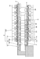
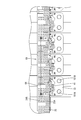
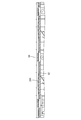
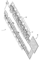
- FIG. 1 Perspective view of the electricity storage module of the embodiment
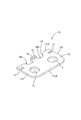
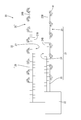
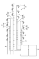
- the perspective view of the bus bar of the embodiment The top view of the flexible printed circuit board of embodiment Development view of the flexible printed circuit board of the embodiment
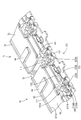
- the perspective view of the resin protector of the embodiment Partial enlarged view of frame R3 in FIG. In the resin protector, the partial expansion perspective view which expands and shows the circumference
- connection module 1 of the present embodiment constitutes an electricity storage module M used as a drive source for vehicles such as electric vehicles and hybrid vehicles. As shown in FIG. 1, the connection module 1 is attached to a power storage element group 150G in which a plurality of power storage elements 150 are arranged in a line, and connects the plurality of power storage elements 150 in series.
- the power storage element 150 is, for example, a secondary battery. As shown in FIG. 1, each power storage element 150 has a flat rectangular parallelepiped shape, and has an electrode placement surface 150F (upper surface in FIG. 1) perpendicular to a surface facing the adjacent power storage element 150. ing.
- the electrode terminals 151A and 151B are arranged on the electrode arrangement surface 150F.
- One of the electrode terminals 151A and 151B is the positive electrode terminal 151A, and the other is the negative electrode terminal 151B.
- Each of the electrode terminals 151A and 151B has a columnar shape, and although not shown in detail, the outer peripheral surface is threaded.
- a plurality of power storage elements 150 are arranged in a line to form a power storage element group 150G.
- two adjacent power storage elements 150 have electrode terminals 151A and 151B of different polarities adjacent to each other (that is, the positive electrode terminal 151A of one power storage element 150 and another adjacent to this).
- the negative electrode terminal 151B of the power storage element 150 is arranged so as to be adjacent to each other.
- connection module 1 is a module that is assembled to the surface (upper surface in FIG. 1) formed by the electrode placement surface 150F of each power storage element 150 in the power storage element group 150G. As shown in FIG. 2, the connection module 1 is connected to the flexible printed circuit board 20 (hereinafter, referred to as “FPC20”) and the FPC20 to connect the positive electrode terminal 151A and the negative electrode terminal 151B of the adjacent power storage elements 150.
- FPC20 flexible printed circuit board 20
- a plurality of bus bars 10 (corresponding to a connecting member) and a resin protector 50 (corresponding to a holding member) that holds the bus bar 10 and the FPC 20 are provided.
- Each of the plurality of bus bars 10 is made of metal, and as shown in FIG. 7, an electrode connecting portion 11 that connects the positive electrode terminal 151 ⁇ / b> A and the negative electrode terminal 151 ⁇ / b> B of the adjacent power storage elements 150, and from this electrode connecting portion 11. It is provided with an FPC connection piece 15 that is continuous and is connected to the FPC 20, and a locking wall 16 that is continuous from the FPC connection piece 15.
- the electrode connection portion 11 is a rectangular plate-shaped portion as a whole, and has two electrode insertion holes 12 through which the electrode terminals 151A and 151B can be inserted and two engagement recesses for engaging the resin protector 50. 13 and 13.
- One electrode insertion hole 12 is arranged at a position close to one short side 11S of the electrode connecting portion 11, and one is arranged at a position close to the other short side 11S.
- One of the two engaging recesses 13 is a recess recessed from one short side 11S of the electrode connecting part 11, and the other is a recess recessed from the other short side 11S.
- the electrode connecting portion 11 has a connection recess 14 that is recessed from one long side 11LA of the pair of long sides 11LA and 11LB.
- the connection recess 14 is a recess defined by a first inner edge 14A parallel to the long side 11LA and a pair of first side edges 14B connecting both ends of the first inner edge 14A and the long side 11LA. ..
- the FPC connection piece 15 is a rectangular plate piece-shaped portion extending from the first inner edge 14A in the same plane as the electrode connection portion 11.
- the locking wall 16 is a short plate wall-shaped portion that extends vertically from the tip of the FPC connection piece 15.
- the FPC 20 is a member for electrically connecting the plurality of bus bars 10 and the ECU (electronic control unit: not shown). Although not shown in detail, the FPC 20 has a plurality of conductive paths formed of copper foil. , And an insulating resin film that covers both surfaces of the conductive path. As shown in FIG. 9, the FPC 20 includes an FPC main body 21 and a plurality of first movable portions 41 connected from the FPC main body 21 and connected to the plurality of bus bars 10, respectively.
- the FPC main body 21 includes an external connection portion 22 connected to the ECU and six wiring portions (first wiring portion 23, second wiring portion 24, third wiring portion) connected to the external connection portion 22.
- the 1st wiring part 23 is provided with the 1st expansion-contraction part 23A extended from the external connection part 22, and the 1st bus-bar arrangement
- positioning part 23B which continues from the extension end of the 1st expansion-contraction part 23A, and is an elongated strip-shaped part as a whole. is there.
- the first stretchable portion 23A is lightly bent along a plurality of folding lines 29, so that the first stretchable portion 23A is bent into a gentle corrugated shape in which mountain-shaped portions and valley-shaped portions are alternately arranged (see also FIG. 6). See also), and it can be expanded and contracted by changing the folding angle. As a result, the displacement of the first bus bar arranging portion 23B in the direction toward and away from the external connecting portion 22 is allowed.
- the second wiring portion 24 includes a second stretchable portion 24A extending from the external connection portion 22 and a second bus bar arrangement portion 24B connected from the extended end of the second stretchable portion 24A.
- the fourth wiring portion 26 includes a fourth expansion / contraction portion 26A extending from the external connection portion 22 and a fourth bus bar arrangement portion 26B continuous from the extending end of the fourth expansion / contraction portion 26A.
- the fifth wiring portion 27 includes a fifth expansion / contraction portion 27A extending from the external connection portion 22 and a fifth bus bar arrangement portion 27B continuous from the extending end of the fifth expansion / contraction portion 27A.
- the configurations of the second stretchable portion 24A, the fourth stretchable portion 26A, and the fifth stretchable portion 27A are the same as the first stretchable portion 23A, except that the lengths are different.
- the third wiring portion 25 and the sixth wiring portion 28 extend from the external connection portion 22.
- the third wiring portion 25 is different from the above four wiring portions 23, 24, 26 and 27 in that it does not have a stretchable portion.
- the six wiring portions 23, 24, 25, 26, 27, 28 extend in the same direction from the external connection portion 22 and are arranged in parallel.
- the first movable portion 41 is an S-shaped wire spring-shaped portion that is continuous from the FPC main body 21. As shown in FIG. 9, a part of the plurality of first movable parts 41 is connected to the third wiring part 25, another part is connected to the sixth wiring part 28, and the rest is a plurality of parts. Each of them is connected from each of the four bus bar arrangement portions 23B, 24B, 26B, 27B.
- the tip end of the first movable portion 41 is a joining piece in which a part of the conductive path is exposed as a joining land (not shown), and the FPC connecting piece 15 is connected thereto by soldering.
- the external connection portion 22 is folded along the mountain fold line shown by the broken line in FIG. 9 and the valley fold line shown by the alternate long and short dash line.
- the first wiring portion 23, the second wiring portion 24, and the third wiring portion 25 form a set of stacked portions (first stacked portion 31), and the fourth wiring The portion 26, the fifth wiring portion 27, and the sixth wiring portion 28 form another set of laminated portions (second laminated portion 32).
- the first laminated portion 31 includes a second layer formed by the first wiring portion 23 on a first layer formed by the second wiring portion 24 and the third wiring portion 25. It has a stacked two-layer structure.
- the third wiring portion 25, the second bus bar arrangement portion 24B, and the first bus bar arrangement portion 23B are arranged in a line in this order from the side closer to the external connection portion 22, and the third wiring
- the plurality of first movable portions 41 connected to the portion 25, the second bus bar arrangement portion 24B, and the first bus bar arrangement portion 23B are also arranged in a line.
- the second layer formed by the fourth wiring portion 26 is stacked on the first layer formed by the fifth wiring portion 27 and the sixth wiring portion 28. It has a layered structure.
- the sixth wiring section 28, the fifth bus bar arranging section 27B, and the fourth bus bar arranging section 26B are arranged in a line in this order from the side closer to the external connection section 22.
- the plurality of first movable portions 41 connected to the portion 28, the fifth bus bar arrangement portion 27B, and the fourth bus bar arrangement portion 26B are also arranged in a line.
- the first busbar placement part 23B is allowed to be displaced in the direction of approaching / separating from the second busbar placement part 24B arranged adjacently.
- the second bus bar disposition part 24B is allowed to be displaced in a direction in which the second bus bar disposition part 24B approaches and separates from the first bus bar disposition part 23B and the third wiring part 25 which are arranged adjacently.
- the fourth busbar disposition part 26B is allowed to be displaced in the direction of approaching / separating with respect to the adjacent fifth busbar disposition part 27B.
- the fifth bus bar arrangement part 27B is allowed to be displaced in the direction of approaching / separating from the fourth bus bar disposing part 26B and the sixth wiring part 28 which are arranged adjacently. There is. Accordingly, it is possible to cope with the positional deviation of the electrode terminals 151A and 151B due to the dimensional tolerance of the storage element group 150G.
- the resin protector 50 is made of synthetic resin, and as shown in FIG. 10, is composed of a first protector 50A holding the first laminated portion 31 and a second protector 50B holding the second laminated portion 32. There is.
- the configuration of the second protector 50B is substantially the same as the configuration of the first protector 50A except for details such as the locking structure for the second laminated portion 32, and therefore the first protector 50A will be described below as an example.
- the first protector 50A is a member that holds the first laminated portion 31, and as shown in FIG. 10, a first FPC holding portion 51 that holds the FPC main body 21 and a plurality of bus bar holding portions 121 that hold the bus bar 10. , 131.
- the first FPC holding unit 51 includes three holding units (first holding unit 61, second holding unit 71, third holding unit 81) and adjacent holding units 61, 71.
- Two first connecting portions 91 for connecting 81 are provided, and the overall shape is an elongated rectangular plate having a size substantially equal to that of the first stacking portion 31.
- the first holding unit 61 is a unit that holds the third wiring portion 25, the second stretchable portion 24A, and the portion of the first stretchable portion 23A that overlaps the third wiring portion 25.
- the second holding unit 71 is a unit that holds the second bus bar arrangement portion 24B and a portion of the first expansion / contraction portion 23A that overlaps the second bus bar arrangement portion 24B.
- the third holding unit 81 is a unit that holds the first bus bar placement portion 23B.
- the first holding unit 61 includes a first mounting plate 62, first side ribs 63 that stand up from the first mounting plate 62, and a plurality of pressing members that are continuous from the first side ribs 63. And a piece 64.
- the first mounting plate 62 is a rectangular plate-shaped portion as a whole, as shown in FIG.
- the first side rib 63 is a stripe-shaped portion that projects from one of the long sides 62LA, 62LB of the first mounting plate 62 (upper side in FIG. 11).
- each of the plurality of pressing pieces 64 is an elongated plate piece-shaped portion that extends from the first side rib 63 in parallel with the first mounting plate 62, and is a part of the first mounting plate 62.
- the first laminated portion 31 can be sandwiched and held between them.
- the second holding unit 71 includes a second mounting plate 72, second side ribs 73 rising from the second mounting plate 72, and a plurality of holding pieces 64 connected from the second side ribs 73.
- the third holding unit 81 includes a third mounting plate 82, a third side rib 83 that rises from the third mounting plate 82, and a plurality of pressing pieces 84 that are continuous from the third side rib 83.
- Each of the two first connecting portions 91 is a leaf spring-shaped portion bent in a W shape, as shown in FIG.
- one first connecting portion 91 is a portion that connects the first placing plate 62 and the second placing plate 72, and one end of the W-shape is the first placing part.
- the short side 62S of the plate 62 is connected to the short side 72S of the second mounting plate 72 at the other end.
- the other first connecting portion 91 similarly connects the second mounting plate 72 and the third mounting plate 82.
- one of the first holding unit 61 located at the end opposite to the second holding unit 71 and the second holding unit 81 of the second holding unit 81 is a fixed bus bar holding part 131, and the other is a movable bus bar holding part 121 connected to the holding units 61, 71, 81 via the second movable part 111. Is.
- the 2nd movable part 111 which connects with the 1st holding
- the same configurations are denoted by the same reference numerals and description thereof will be omitted.
- the first mounting plate 62 has a plurality of spring recesses 101 that are recessed inward from the other (lower side in FIG. 11) long side 62LB of the pair of long sides 62LA and 62LB. ..
- Each spring recess 101 is a recess defined by a second inner edge 101A parallel to the long side 62LB and a pair of second side edges 101B connecting both ends of the second inner edge 101A and the long side 62LB. ..
- the second movable portion 111 is a leaf spring-shaped portion that extends while bending from the second inner edge 101A, extends perpendicularly to the first mounting plate 62, and is then folded back. And an S-shape that extends so as to approach the first mounting plate 62, is folded back, and extends away from the first mounting plate 62.
- Two adjacent two of the second movable portions 111 form a pair and are connected to one movable bus bar holding portion 121.
- the movable bus bar holding portion 121 includes a back plate portion 122 continuous from the second movable portion 111, a bottom plate portion 123 continuous from the back plate portion 122, and an extension piece 125 extending from the bottom plate portion 123.
- the first bus bar locking piece 126 and the two second bus bar locking pieces 127 are provided.
- the back plate part 122 is a plate-shaped part arranged in a posture perpendicular to the first mounting plate 62, and is provided at the tip of each of the pair of second movable parts 111. It is connected.
- the bottom plate portion 123 is a plate-shaped portion that extends vertically from the back plate portion 122 in a direction opposite to the first mounting plate 62, and has two slits 124. ing. Each of the two slits 124 extends from the extended end of the bottom plate portion 123 toward the back plate portion 122, and the slits cause the bottom plate portion 123 to have end plate portions 123A at both ends and a center portion. It is divided into a plate portion 123B. As shown in FIG. 14, the extension piece 125 is a plate-like portion that extends from the extending end of the middle plate portion 123B on the same plane as the bottom plate portion 123.
- the first bus bar locking piece 126 extends from the middle plate portion 123B and is arranged with a gap from the back plate portion 122, and the first bending piece 126A and the first bending piece 126A.
- a first locking claw 126B that projects from the extending end in the direction opposite to the back plate 122 is provided.
- the first bending piece 126A is slightly inclined so as to be farther from the back plate portion 122 as it is farther from the middle plate portion 123B.
- Each of the two second bus bar locking pieces 127 extends from each of the two end plate portions 123A, as shown in FIG. Although not shown in detail, each of the second bus bar locking pieces 127 faces the back plate portion 122 from the second bending piece that extends vertically from the extended end of the two end plate portions 123A and the tip of the second bending piece. And a second locking claw that protrudes.
- the fixed busbar holding portion 131 does not have the second movable portion 111, and is similar to the movable busbar holding portion 121 except that the back plate portion extends from the long side 62LB of the first mounting plate 62.
- the same parts as those of the movable bus bar holding part 121 are designated by the same reference numerals and the description thereof will be omitted.
- the plurality of bus bar holding portions 121 and 131 are arranged in a line as shown in FIG. 10, and the movable bus bar holding portions 121 adjacent to each other are connected by a U-shaped second connecting portion 141 as shown in FIG. It is connected. Similarly, the fixed bus bar holding part 131 and the movable bus bar holding part 121 which are adjacent to each other are also connected by the second connecting part 141.
- connection module 1 An example of a procedure for assembling the connection module 1 having the above configuration will be described below.
- each bus bar 10 connects multiple bus bars 10 to the FPC 20.
- the FPC connecting piece 15 of each bus bar 10 is overlaid on each joining piece of the FPC 20 and joined by reflow soldering.
- Each bus bar 10 is in a state of being connected to the FPC main body 21 via the first movable portion 41, and by the deformation of the first movable portion 41, each bus bar 10 is free to some extent with respect to the FPC main body 21. Can be displaced.
- the joined body of the FPC 20 and the plurality of bus bars 10 is assembled to the resin protector 50.
- the first laminated portion 31 is assembled to the first protector 50A.
- the first stacked unit 31 is stacked on the mounting plates 62, 72, 82 so as to be inserted into the gaps between the pressing pieces 64, 84 and held by the first FPC holding unit 51.
- the height of the pressing piece 64 from the first mounting plate 62 is larger than the thickness of the first laminated portion 31, and as shown in FIG. 4, the second elastic portion 24A is allowed to bend to some extent. In this state, it is sandwiched and held between the pressing piece 64 and the first mounting plate 62.
- the first expansion / contraction portion 23A is also held in a state in which the bending deformation is allowed to some extent.
- the second laminated portion 32 is similarly assembled to the second protector 50B.
- each bus bar 10 is assembled to each bus bar holding portion 121, 131. While bending the first bus bar locking piece 126 and the second bus bar locking piece 127, the electrode connecting portion 11 is pushed toward the bottom plate portion 123. When the electrode connecting portion 11 comes into contact with the bottom plate portion 123, as shown in FIG. 6, the first bus bar locking piece 126 elastically returns, and the locking wall 16 becomes the middle plate portion 123B and the first locking claw 126B. Sandwiched between. Further, the second bus bar locking piece 127 is inserted into the engaging recess 13 and engages with the electrode connecting portion 11. In this way, each bus bar 10 is fixed to each bus bar holding portion 121, 131.
- the first movable portion 41 of the bus bar 10 is allowed to be displaced to some extent with respect to the FPC main body 21, so that the bus bar 10 can be easily assembled to the bus bar holding portions 121 and 131. It can be carried out. Further, by simply pushing the bus bar 10 toward the bottom plate portion 123, it can be easily assembled to the bus bar holding portions 121 and 131.
- connection module 1 Assembly of Connection Module 1 to Storage Element Group 150G
- An example of a procedure for assembling the connection module 1 having the above configuration to the storage element group 150G will be described below.
- connection module 1 is arranged at a predetermined position on the storage element group 150G, and the electrode terminals 151A and 151B are inserted into the electrode insertion holes 12 of each bus bar 10. After that, nuts (not shown) are screwed onto the electrode terminals 151A and 151B to connect the electrode terminals 151A and 151B and the bus bar 10.
- the first protector 50A is assembled along one of the two columns of the electrode terminals 151A and 151B (the lower right column in FIG. 1) to form the first laminated portion 31.
- the bus bar 10 connected to the first wiring portion 23, the second wiring portion 24, and the third wiring portion 25 is connected to the electrode terminals 151A and 151B forming one row.
- the second protector 50B is assembled along the other column of the electrode terminals 151A and 151B (upper left column in FIG. 1), and the fourth wiring portion 26 and the fifth wiring portion 27 that form the second laminated portion 32.
- the bus bar 10 connected to the sixth wiring portion 28 is connected to the electrode terminals 151A and 151B forming the other row.
- the first laminated portion 31 assembled to one row of the electrode terminals 151A and 151B is formed by laminating a plurality of wiring portions 23, 24, 25.
- each wiring part is provided. It is possible to reduce the widths of the wirings 23, 24 and 25 and the width of the first laminated portion 31 formed by the wiring portions 23, 24 and 25. The same applies to the second laminated portion 32. As a result, the wiring route can be accommodated in the limited wiring space on the storage element group 150G.
- connection module 1 includes a resin protector 50
- the resin protector 50 includes a first protector 50A and a second protector 50B.
- the first protector 50A holds the first laminated portion 31 and the bus bar 10 connected to the wiring portions 23, 24, 25 forming the first laminated portion 31.
- the first protector 50A holds the plurality of wiring portions 23, 24, and 25 together and holds the plurality of bus bars 10 together, and collectively holds the plurality of bus bars 10 at a predetermined position on the storage element group 150G. Can be set to.
- the second protector 50B the plurality of wiring portions 26, 27, 28 can be collectively held together with the plurality of bus bars 10 in a stacked state, and can be collectively set at a predetermined position on the storage element group 150G. it can. As a result, workability of assembling the connection module 1 to the power storage element group 150G can be improved.
- the displacement between the first bus bar arrangement portion 23B, the second bus bar arrangement portion 24B and the third wiring portion 25 is allowed. Accordingly, it is possible to cope with the positional deviation of the electrode terminals 151A and 151B due to the dimensional tolerance of the storage element group 150G.
- the first expansion / contraction portion 23A is bent to reduce the length, and the first bus bar arrangement portion 23B and the second The distance from the bus bar placement portion 24B can be reduced.
- the second expansion / contraction portion 24A can be bent to reduce its length, and the distance between the second bus bar arrangement portion 24B and the third wiring portion 25 can be reduced.
- the first expansion / contraction portion 23A is extended to form the first bus bar arrangement portion 23B and the second bus bar arrangement portion 24B. The distance can be increased.
- the second expansion / contraction part 24A can be extended to increase the distance between the second bus bar placement part 24B and the third wiring part 25. The same applies to the second laminated portion 32.
- the distance between the three holding units 61, 71 and 81 in the first protector 50A varies. Since it is allowed, the first protector 50A does not hinder the displacement between the first bus bar arrangement portion 23B, the second bus bar arrangement portion 24B, and the third wiring portion 25. The same applies to the second protector 50B.
- the connection module 1 is a module that is attached to the storage element group 150G configured by the plurality of storage elements 150 including the electrode terminals 151A and 151B to connect the plurality of storage elements 150. Therefore, the FPC 20 including the plurality of wiring portions 23, 24, 25, 26, 27, 28 and the electrode terminal 151A of the adjacent power storage element 150 connected to the wiring portions 23, 24, 25, 26, 27, 28. , 151B for connecting each other, and the FPC 20 being folded, the plurality of wiring portions 23, 24, 25 are laminated to form the first laminated portion 31, and the plurality of wiring portions 23, 24, 25 are formed. The wiring portions 26, 27, 28 are laminated to form a second laminated portion 32.
- the wiring portions 23, 24, 25, 26, 27, 28 of the wiring portions 23, 24, 25, 26, 27, 28 are compared with the case where the wirings (conductive paths) corresponding to all the bus bars 10 are housed in the wiring route of one layer. Since the width can be reduced, the wiring route can be accommodated in the limited wiring space on the storage element group 150G.
- connection module 1 also includes a resin protector 50 that holds the plurality of bus bars 10, the first laminated portion 31, and the second laminated portion 32.
- the plurality of wiring portions 23, 24, 25, 26, 27, 28 are stacked and held together with the plurality of bus bars 10 and are collectively set on the power storage element group 150G. Can be set in position. As a result, the workability of assembling the connection module 1 to the power storage element group 150G can be improved.
- the technology disclosed in the present specification is not limited to the embodiments described by the above description and the drawings, and includes various aspects such as the following.
- the first laminated portion 31 is composed of the three wiring portions 23, 24, 25, but the laminated portion may be composed of two or four or more wiring routes. Absent.
- the first laminated portion 31 has a two-layer structure, but the laminated portion may be composed of three or more layers.
- the first layer is composed of the second wiring part 24 and the third wiring part 25, and the second layer is composed of the first wiring part 23.
- one layer is three or more. It may be configured by the wiring route of.
- the method of folding the flexible printed circuit board to form the laminated portion is not limited to the above embodiment, and for example, a long flexible printed circuit board is folded along a fold line perpendicular to the side edge. It doesn't matter.
- the resin protector 50 includes the pressing pieces 64 and 84.
- the holding member is not limited to the above-described embodiment in the configuration for holding the flexible printed circuit board, and the holding member is provided in the holding member, for example.
- the pin may be inserted into a pin hole provided on the flexible printed board, or the flexible printed board may be engaged with a locking piece provided on the holding member.
- Connection module 10 ... Bus bar (connection member) 20 ... FPC (flexible printed circuit board) 23 ... 1st wiring part (wiring route) 24 ... Second wiring part (routed route) 25 ... Third wiring section (routed route) 26 ... 4th wiring part (wiring route) 27 ... Fifth wiring section (routed route) 28 ... 6th wiring part (wiring route) 31 ... First laminated portion (laminated portion) 32 ... Second laminated portion (laminated portion) 50 ... Resin protector (holding member) 150 ... Storage element 150G ... Storage element group 151A ... Positive electrode terminal (electrode terminal) 151B ... Negative electrode terminal (electrode terminal)
Landscapes
- Engineering & Computer Science (AREA)
- Microelectronics & Electronic Packaging (AREA)
- Chemical & Material Sciences (AREA)
- Chemical Kinetics & Catalysis (AREA)
- Electrochemistry (AREA)
- General Chemical & Material Sciences (AREA)
- Connection Of Batteries Or Terminals (AREA)
- Battery Mounting, Suspending (AREA)
Abstract
接続モジュール1は、電極端子151A、151Bを備える複数の蓄電素子150により構成される蓄電素子群150Gに取り付けられて複数の蓄電素子150を接続するモジュールであって、複数の配線部23、24、25、26、27、28を備えるFPC20と、配線部23、24、25、26、27、28に接続されて、隣り合う蓄電素子150の電極端子151A、151B同士を接続する複数のバスバー10とを備え、FPC20が折り畳まれていることにより、複数の配線部23、24、25が積層されて第1積層部31を構成しているとともに、複数の配線部26、27、28が積層されて第2積層部32を構成している。
Description
本明細書によって開示される技術は、接続モジュールに関する。
電気自動車やハイブリット車用の電池モジュールは、複数の電池セルにより構成される電池ブロックと、この電池ブロックに取り付けられて複数の単電池を接続する接続モジュールとを備えている。接続モジュールとして、フレキシブルプリント基板(FPC)と、このフレキシブルプリント基板に接続され、隣り合う蓄電素子の電極端子同士を接続する複数のバスバーとを備えるバスバー付きフレキシブルプリント配線板が知られている(特許文献1参照)。
上記の構成では、多数の電池セルに対応して、多数のバスバーが必要となるため、1枚のフレキシブルプリント基板に、これらすべてのバスバーに対応する導電路を含めようとすると、フレキシブルプリント基板の幅が大きくなってしまう。電池ブロック上の接続モジュールの配索スペースには限りがあるため、フレキシブルプリント基板の幅が大きくなりすぎると、接続モジュールの組み付けが困難となってしまうことが懸念される。
本明細書によって開示される接続モジュールは、電極端子を備える複数の蓄電素子により構成される蓄電素子群に取り付けられて前記複数の蓄電素子を接続する接続モジュールであって、複数の配索経路を備えるフレキシブルプリント基板と、前記配索経路に接続されて、隣り合う前記蓄電素子の前記電極端子同士を接続する複数の接続部材とを備え、前記フレキシブルプリント基板が折り畳まれていることにより、前記複数の配索経路が積層されて積層部を構成している。
上記の構成によれば、全ての接続部材に対応する配線を、1層の配索経路に収めた場合と比較して、配索経路の幅を小さくすることができるから、蓄電素子群上の限られた配索スペース内に配索経路を収めることができる。
上記の構成において、接続モジュールが、複数の前記接続部材と前記積層部とを保持する保持部材を備えていても構わない。
このような構成によれば、複数の配索経路を積層した状態で、複数の接続部材とともにまとめて保持し、一括して蓄電素子群上の所定位置にセットすることができる。これにより、接続モジュールの蓄電素子群への組み付け作業性を向上させることができる。
本明細書によって開示される接続モジュールによれば、蓄電素子群上の限られた配索スペース内に配索経路を収めることができる。
実施形態を、図1~図15を参照しつつ説明する。本実施形態の接続モジュール1は、電気自動車やハイブリット自動車等の車両の駆動源として使用される蓄電モジュールMを構成する。接続モジュール1は、図1に示すように、複数の蓄電素子150が一列に並べられた蓄電素子群150Gに取り付けられて、複数の蓄電素子150を直列に接続する。
[蓄電素子150および蓄電素子群150G]
蓄電素子150は、例えば、二次電池である。各蓄電素子150は、図1に示すように、外形が扁平な直方体状であって、隣接する蓄電素子150と対向する面に対して垂直な電極配置面150F(図1の上面)を有している。電極配置面150Fには、電極端子151A、151Bが配置されている。電極端子151A、151Bのうち一方は正極端子151Aであり、他方は負極端子151Bである。各電極端子151A、151Bは円柱状であって、外周面には、詳細には図示しないが、ねじ山が切られている。
蓄電素子150は、例えば、二次電池である。各蓄電素子150は、図1に示すように、外形が扁平な直方体状であって、隣接する蓄電素子150と対向する面に対して垂直な電極配置面150F(図1の上面)を有している。電極配置面150Fには、電極端子151A、151Bが配置されている。電極端子151A、151Bのうち一方は正極端子151Aであり、他方は負極端子151Bである。各電極端子151A、151Bは円柱状であって、外周面には、詳細には図示しないが、ねじ山が切られている。
図1に示すように、複数の蓄電素子150が一列に並べられて蓄電素子群150Gを構成している。複数の蓄電素子150は、隣り合う2つの蓄電素子150において、異なる極性の電極端子151A、151Bが互いに隣り合うように(つまり、一の蓄電素子150の正極端子151Aと、これと隣接する他の蓄電素子150の負極端子151Bとが互いに隣り合うように)並べられている。
[接続モジュール1]
接続モジュール1は、蓄電素子群150Gにおいて、各蓄電素子150の電極配置面150Fによって構成される面(図1の上面)に組み付けられるモジュールである。接続モジュール1は、図2に示すように、フレキシブルプリント基板20(以下、「FPC20」と記載する)と、FPC20に接続されて、隣り合う蓄電素子150の正極端子151Aと負極端子151Bとを接続する複数のバスバー10(接続部材に該当)と、バスバー10とFPC20とを保持する樹脂プロテクタ50(保持部材に該当)とを備えている。
接続モジュール1は、蓄電素子群150Gにおいて、各蓄電素子150の電極配置面150Fによって構成される面(図1の上面)に組み付けられるモジュールである。接続モジュール1は、図2に示すように、フレキシブルプリント基板20(以下、「FPC20」と記載する)と、FPC20に接続されて、隣り合う蓄電素子150の正極端子151Aと負極端子151Bとを接続する複数のバスバー10(接続部材に該当)と、バスバー10とFPC20とを保持する樹脂プロテクタ50(保持部材に該当)とを備えている。
(バスバー10)
複数のバスバー10のそれぞれは、金属製であって、図7に示すように、隣り合う蓄電素子150の正極端子151Aと負極端子151Bとを接続する電極接続部11と、この電極接続部11から連なり、FPC20に接続されるFPC接続片15と、FPC接続片15から連なる係止壁16とを備えている。
複数のバスバー10のそれぞれは、金属製であって、図7に示すように、隣り合う蓄電素子150の正極端子151Aと負極端子151Bとを接続する電極接続部11と、この電極接続部11から連なり、FPC20に接続されるFPC接続片15と、FPC接続片15から連なる係止壁16とを備えている。
電極接続部11は、全体として長方形の板状の部分であって、電極端子151A、151Bを挿通可能な2つの電極挿通孔12と、樹脂プロテクタ50との係合のための2つの係合凹部13とを有している。電極挿通孔12は、電極接続部11の一方の短辺11Sに近接した位置に1つ、他方の短辺11Sに近接した位置に1つが配置されている。2つの係合凹部13のうち一方は、電極接続部11の一方の短辺11Sから凹む凹部であり、他方は、他方の短辺11Sから凹む凹部である。
電極接続部11は、一対の長辺11LA、11LBのうち一方の長辺11LAから凹む接続用凹部14を有している。この接続用凹部14は、長辺11LAと平行な第1奥縁14Aと、この第1奥縁14Aの両端と長辺11LAとを繋ぐ一対の第1側縁14Bとで定義される凹部である。FPC接続片15は、第1奥縁14Aから電極接続部11と同一平面内に延びる矩形の板片状の部分である。係止壁16は、FPC接続片15の先端から垂直に延びる短い板壁状の部分である。
(FPC20)
FPC20は、複数のバスバー10とECU(電子制御ユニット:図示せず)とを電気的に接続するための部材であって、詳細には図示しないが、銅箔によって形成された複数の導電路と、導電路の両面を被覆する絶縁樹脂フィルムとを備えている。このFPC20は、図9に示すように、FPC本体21と、FPC本体21から連なり、複数のバスバー10のそれぞれに接続される複数の第1可動部41とを備えている。
FPC20は、複数のバスバー10とECU(電子制御ユニット:図示せず)とを電気的に接続するための部材であって、詳細には図示しないが、銅箔によって形成された複数の導電路と、導電路の両面を被覆する絶縁樹脂フィルムとを備えている。このFPC20は、図9に示すように、FPC本体21と、FPC本体21から連なり、複数のバスバー10のそれぞれに接続される複数の第1可動部41とを備えている。
FPC本体21は、図9に示すように、ECUと接続される外部接続部22と、この外部接続部22から連なる6つの配線部(第1配線部23、第2配線部24、第3配線部25、第4配線部26、第5配線部27および第6配線部28:いずれも配索経路に該当)を備えている。
第1配線部23は、外部接続部22から延びる第1伸縮部23Aと、第1伸縮部23Aの延出端から連なる第1バスバー配置部23Bとを備えており、全体として細長い帯状の部分である。第1伸縮部23Aは、複数の折り線29に沿って軽く折り曲げられることで、山状の部分と谷状の部分とが交互に並んだ緩やかな波型に屈曲されており(図6を併せて参照)、折り角度が変化することで、伸縮可能となっている。これにより、第1バスバー配置部23Bの、外部接続部22に対して近接-離間する方向の変位が許容されている。
第2配線部24は、同様に、外部接続部22から延びる第2伸縮部24Aと、第2伸縮部24Aの延出端から連なる第2バスバー配置部24Bとを備えている。第4配線部26は、同様に、外部接続部22から延びる第4伸縮部26Aと、第4伸縮部26Aの延出端から連なる第4バスバー配置部26Bとを備えている。第5配線部27は、同様に、外部接続部22から延びる第5伸縮部27Aと、第5伸縮部27Aの延出端から連なる第5バスバー配置部27Bとを備えている。第2伸縮部24A、第4伸縮部26A、および第5伸縮部27Aの構成は、長さが異なる点を除き、第1伸縮部23Aと同様である。
第3配線部25および第6配線部28は、外部接続部22から延びている。この第3配線部25は、伸縮部を有していない点で、上記4つの配線部23、24、26、27と異なっている。
6つの配線部23、24、25、26、27、28は、外部接続部22から同方向に延び、並列して配置されている。
第1可動部41は、図3および図9に示すように、FPC本体21から連なるS字の線ばね状の部分である。図9に示すように、複数の第1可動部41のうち一部は、第3配線部25から連なっており、他の一部は、第6配線部28から連なっており、残りは、複数個ずつが、4つのバスバー配置部23B、24B、26B、27Bのそれぞれから連なっている。第1可動部41の先端部は、導電路の一部が接合用ランド(図示せず)として露出された接合片となっており、ここに、FPC接続片15が半田付けにより接続される。
FPC本体21は、外部接続部22が、図9に破線で示す山折り線、および、1点鎖線で示す谷折り線にそって折り畳まれている。これにより、図8に示すように、第1配線部23、第2配線部24および第3配線部25が、一組の積層部(第1積層部31)を構成しており、第4配線部26、第5配線部27および第6配線部28が、他の一組の積層部(第2積層部32)を構成している。
第1積層部31は、図8に示すように、第2配線部24と第3配線部25とで構成される第1層の上に、第1配線部23により構成された第2層が重ねられた2層構造をなしている。第1積層部31において、第3配線部25と、第2バスバー配置部24Bと、第1バスバー配置部23Bとは、外部接続部22に近い方からこの順に一列に並んでおり、第3配線部25と、第2バスバー配置部24Bと、第1バスバー配置部23Bとに連なる複数の第1可動部41も、一列に並んでいる。
同様に、第2積層部32は、第5配線部27と第6配線部28とで構成される第1層の上に、第4配線部26により構成される第2層が重ねられた2層構造をなしている。第2積層部32において、第6配線部28と、第5バスバー配置部27Bと、第4バスバー配置部26Bとは、外部接続部22に近い方からこの順に一列に並んでおり、第6配線部28と、第5バスバー配置部27Bと、第4バスバー配置部26Bとに連なる複数の第1可動部41も、一列に並んでいる。
第1伸縮部23Aの伸縮により、第1バスバー配置部23Bは、隣りに配置された第2バスバー配置部24Bに対して近接-離間する方向の変位が許容されている。また、第2伸縮部24Aの伸縮により、第2バスバー配置部24Bは、隣りに配置された第1バスバー配置部23Bおよび第3配線部25に対して近接-離間する方向の変位が許容されている。同様に、第4伸縮部26Aの伸縮により、第4バスバー配置部26Bは、隣りに配置された第5バスバー配置部27Bに対して近接-離間する方向の変位が許容されている。また、第5伸縮部27Aの伸縮により、第5バスバー配置部27Bは、隣りに配置された第4バスバー配置部26Bおよび第6配線部28に対して近接-離間する方向の変位が許容されている。これらにより、蓄電素子群150Gの寸法公差に起因する電極端子151A、151Bの位置ずれに対応することができる。
(樹脂プロテクタ50)
樹脂プロテクタ50は、合成樹脂製であって、図10に示すように、第1積層部31を保持する第1プロテクタ50Aと、第2積層部32を保持する第2プロテクタ50Bとで構成されている。第2プロテクタ50Bの構成は、第2積層部32に対する係止構造等の細部を除き、第1プロテクタ50Aの構成と概ね同様であるので、以下には、第1プロテクタ50Aを例にとり説明する。
樹脂プロテクタ50は、合成樹脂製であって、図10に示すように、第1積層部31を保持する第1プロテクタ50Aと、第2積層部32を保持する第2プロテクタ50Bとで構成されている。第2プロテクタ50Bの構成は、第2積層部32に対する係止構造等の細部を除き、第1プロテクタ50Aの構成と概ね同様であるので、以下には、第1プロテクタ50Aを例にとり説明する。
第1プロテクタ50Aは、第1積層部31を保持する部材であって、図10に示すように、FPC本体21を保持する第1FPC保持部51と、バスバー10を保持する複数のバスバー保持部121、131とを備えている。
第1FPC保持部51は、図10および図13に示すように、3つの保持ユニット(第1保持ユニット61、第2保持ユニット71、第3保持ユニット81)と、隣り合う保持ユニット61、71、81間を連結する2つの第1連結部91とを備えて、全体として第1積層部31とほぼ同等の大きさの細長い長方形の板状をなしている。第1保持ユニット61は、第3配線部25と、第2伸縮部24Aと、第1伸縮部23Aにおいて第3配線部25に重なる部分とを保持するユニットである。第2保持ユニット71は、第2バスバー配置部24Bと、第1伸縮部23Aにおいて第2バスバー配置部24Bに重なる部分とを保持するユニットである。第3保持ユニット81は、第1バスバー配置部23Bを保持するユニットである。
第1保持ユニット61は、図11および図13に示すように、第1載置板62と、この第1載置板62から立ち上がる第1サイドリブ63と、この第1サイドリブ63から連なる複数の押さえ片64とを備えている。
第1載置板62は、図13に示すように、全体として長方形の板状をなす部分である。第1サイドリブ63は、図11に示すように、第1載置板62の一対の長辺62LA、62LBのうち一方(図11の上方)の長辺62LAから突出するすじ状の部分である。複数の押さえ片64のそれぞれは、図11に示すように、第1サイドリブ63から、第1載置板62と平行に延びる細長い板片状の部分であって、第1載置板62との間で第1積層部31を挟んで保持できるようになっている。
同様に、第2保持ユニット71は、第2載置板72と、この第2載置板72から立ち上がる第2サイドリブ73と、この第2サイドリブ73から連なる複数の押さえ片64とを備えている。また、第3保持ユニット81は、第3載置板82と、この第3載置板82から立ち上がる第3サイドリブ83と、この第3サイドリブ83から連なる複数の押さえ片84とを備えている。
2つの第1連結部91のそれぞれは、図12に示すように、W字形に屈曲された板ばね状の部分である。一方の第1連結部91は、図11および図14に示すように、第1載置板62と第2載置板72とを連結する部分であって、W字の一端が第1載置板62の短辺62Sに、他端が第2載置板72の短辺72Sに接続されている。他方の第1連結部91は、同様に第2載置板72と第3載置板82とを連結している。これらの第1連結部91によって、3つの保持ユニット61、71、81は、互いに近接-離間する方向に変位可能となっている。これにより、上記した第1バスバー配置部23B-第2バスバー配置部24B-第3配線部25間の変位に追従して、3つの保持ユニット61、71、81間の距離を変動させることができる。
図10に示すように、複数のバスバー保持部121、131のうち、第1保持ユニット61において第2保持ユニット71とは反対側の端に位置する1つ、第3保持ユニット81において第2保持ユニット71とは反対側の端に位置する1つは、固定バスバー保持部131であり、その他は、第2可動部111を介して保持ユニット61、71、81に連結された可動バスバー保持部121である。以下には、第1保持ユニット61から連なる第2可動部111、可動バスバー保持部121および固定バスバー保持部131について説明し、第2保持ユニット71および第3保持ユニット81から連なる第2可動部111およびバスバー保持部121、131については、同様の構成に同一の符号を付して説明を省略する。
図14に示すように、第1載置板62は、一対の長辺62LA、62LBのうち他方(図11の下方)の長辺62LBから内側に凹む複数のばね用凹部101を有している。各ばね用凹部101は、長辺62LBに平行な第2奥縁101Aと、この第2奥縁101Aの両端と長辺62LBとを繋ぐ一対の第2側縁101Bとで定義される凹部である。
第2可動部111は、図11に示すように、第2奥縁101Aから屈曲しながら延びる板ばね状の部分であって、第1載置板62に対して垂直に延びた後、折り返されて第1載置板62に近づくように延び、さらに折り返されて第1載置板62から離れるように延びるS字状をなしている。この第2可動部111は、隣り合う2つが対をなして1つの可動バスバー保持部121に接続されている。
可動バスバー保持部121は、図11および図14に示すように、第2可動部111から連なる背板部122と、背板部122から連なる底板部123と、底板部123から延びる延長片125、第1バスバー係止片126、および2つの第2バスバー係止片127を備えている。
背板部122は、図11に示すように、第1載置板62に対して垂直な姿勢で配される板状の部分であって、一対の第2可動部111のそれぞれの先端部に接続されている。
底板部123は、図11および図14に示すように、背板部122から、第1載置板62と反対方向に垂直に延びる板状の部分であって、2本のスリット124を有している。2本のスリット124のそれぞれは、底板部123の延出端から背板部122に向かって延びており、これらのスリット124によって、底板部123は、両端の端板部123Aと、中央の中板部123Bとに分割されている。延長片125は、図14に示すように、中板部123Bの延出端から、底板部123と同一面上に延びる板片状の部分である。
第1バスバー係止片126は、図11に示すように、中板部123Bから延び、背板部122に対して隙間を空けて配置される第1撓み片126Aと、第1撓み片126Aの延出端から背板部122と反対方向に突出する第1係止爪126Bとを備えている。第1撓み片126Aは、中板部123Bから離れるほど背板部122から離れるように僅かに傾斜している。
2つの第2バスバー係止片127のそれぞれは、図11に示すように、2つの端板部123Aのそれぞれから延びている。各第2バスバー係止片127は、詳細には図示しないが、2つの端板部123Aの延出端から垂直に延びる第2撓み片と、第2撓み片の先端から背板部122に向かって突出する第2係止爪とを備えている。
固定バスバー保持部131は、第2可動部111を有しておらず、背板部が第1載置板62の長辺62LBから延びている点を除いて、可動バスバー保持部121と同様の構成を有している。固定バスバー保持部131において、可動バスバー保持部121の各部位と同様の部位には、同一の符号を付して説明を省略する。
複数のバスバー保持部121、131は、図10に示すように、一列に並んでおり、隣り合う可動バスバー保持部121同士は、図11に示すように、U字状の第2連結部141により連結されている。同様に、隣り合う固定バスバー保持部131と可動バスバー保持部121も、第2連結部141により連結されている。
[接続モジュール1の組み立て]
上記の構成の接続モジュール1を組み立てる手順の一例を、以下に説明する。
上記の構成の接続モジュール1を組み立てる手順の一例を、以下に説明する。
まず、複数のバスバー10をFPC20に接続する。各バスバー10のFPC接続片15をFPC20の各接合片に重ね、リフロー半田付けによって接合する。各バスバー10は、第1可動部41を介してFPC本体21と連結された状態となっており、第1可動部41が変形することによって、各バスバー10は、FPC本体21に対してある程度自由に変位することができる。
次に、FPC20と複数のバスバー10との接合体を、樹脂プロテクタ50に組み付ける。
まず、第1積層部31を、第1プロテクタ50Aに組み付ける。第1積層部31を、載置板62、72、82上に、押さえ片64、84との隙間に差し入れるようにして重ね、第1FPC保持部51に保持させる。押さえ片64の第1載置板62からの高さは、第1積層部31の厚さよりも大きくなっており、図4に示すように、第2伸縮部24Aは、屈曲変形がある程度許容された状態で、押さえ片64と第1載置板62との間で挟まれて保持される。同様に、第1伸縮部23Aも、屈曲変形がある程度許容された状態で保持される。
第2積層部32も、同様に第2プロテクタ50Bに組み付けられる。
第2積層部32も、同様に第2プロテクタ50Bに組み付けられる。
次に、各バスバー10を各バスバー保持部121、131に組み付ける。第1バスバー係止片126と第2バスバー係止片127とを撓ませつつ、電極接続部11を底板部123に向かって押し込む。電極接続部11が底板部123に当接すると、図6に示すように、第1バスバー係止片126が弾性復帰して、係止壁16が中板部123Bと第1係止爪126Bとの間で挟まれる。また、第2バスバー係止片127が係合凹部13に挿通されて、電極接続部11に係合する。このようにして、各バスバー10が各バスバー保持部121、131に固定される。このとき、バスバー10は、第1可動部41が変形することによって、FPC本体21に対してある程度自由な変位が許容されているので、バスバー10のバスバー保持部121、131に対する組み付け作業を容易に行うことができる。また、バスバー10を底板部123に向かって押し込むだけで、容易にバスバー保持部121、131に組み付けることができる。
[接続モジュール1の蓄電素子群150Gへの組み付け]
上記の構成の接続モジュール1を蓄電素子群150Gに組み付ける手順の一例を、以下に説明する。
上記の構成の接続モジュール1を蓄電素子群150Gに組み付ける手順の一例を、以下に説明する。
図1に示すように、蓄電素子群150G上の所定位置に接続モジュール1を配置し、各バスバー10の電極挿通孔12に電極端子151A、151Bを挿通させる。その後、各電極端子151A、151Bに図示しないナットをねじ付けることにより、電極端子151A、151Bとバスバー10とを接続する。
図1に示すように、第1プロテクタ50Aは、電極端子151A、151Bの2つの列のうち一方の列(図1の右下の列)に沿って組み付けられ、第1積層部31を構成する第1配線部23、第2配線部24および第3配線部25に接続されたバスバー10が、一方の列をなす電極端子151A、151Bに接続される。また、第2プロテクタ50Bは、電極端子151A、151Bの他方の列(図1の左上の列)に沿って組み付けられ、第2積層部32を構成する第4配線部26、第5配線部27および第6配線部28に接続されたバスバー10が、他方の列をなす電極端子151A、151Bに接続される。
ここで、電極端子151A、151Bの一方の列に組み付けられる第1積層部31は、複数の配線部23、24、25が積層されて構成されている。このような構成によれば、電極端子151A、151Bの一方の列に接続される全てのバスバー10に対応する導電路を、1層の配索経路に収めた場合と比較して、各配線部23、24、25の幅、および、これらの配線部23、24、25により構成される第1積層部31の幅を小さくすることができる。第2積層部32についても同様である。これにより、蓄電素子群150G上の限られた配索スペース内に配索経路を収めることができる。
また、接続モジュール1が、樹脂プロテクタ50を備え、この樹脂プロテクタ50は、第1プロテクタ50Aと第2プロテクタ50Bとを備えている。第1プロテクタ50Aは、第1積層部31と、この第1積層部31を構成する配線部23、24、25に接続されたバスバー10とを保持している。このような構成によれば、第1プロテクタ50Aによって、複数の配線部23、24、25を積層した状態で、複数のバスバー10とともにまとめて保持し、一括して蓄電素子群150G上の所定位置にセットすることができる。同様に、第2プロテクタ50Bによって、複数の配線部26、27、28を積層した状態で、複数のバスバー10とともにまとめて保持し、一括して蓄電素子群150G上の所定位置にセットすることができる。これにより、接続モジュール1の蓄電素子群150Gへの組み付け作業性を向上させることができる。
また、上記したように、第1積層部31においては、第1バスバー配置部23B-第2バスバー配置部24B-第3配線部25間の変位が許容されている。これにより、蓄電素子群150Gの寸法公差に起因する電極端子151A、151Bの位置ずれに対応することができる。
例えば、電極端子151A、151B間の距離が設計寸法よりも小さい場合には、図2に示すように、第1伸縮部23Aを屈曲させて長さを縮め、第1バスバー配置部23Bと第2バスバー配置部24Bとの距離を小さくすることができる。同様に、第2伸縮部24Aを屈曲させて長さを縮め、第2バスバー配置部24Bと第3配線部25との距離を小さくすることができる。一方、電極端子151A、151B間の距離が設計寸法よりも大きい場合には、図15に示すように、第1伸縮部23Aを伸長させて第1バスバー配置部23Bと第2バスバー配置部24Bとの距離を大きくすることができる。同様に、第2伸縮部24Aを伸長させて第2バスバー配置部24Bと第3配線部25との距離を大きくすることができる。第2積層部32についても同様である。
また、第1バスバー配置部23B-第2バスバー配置部24B-第3配線部25間の変位に追従して、第1プロテクタ50Aにおいて、3つの保持ユニット61、71、81間の距離の変動が許容されているから、第1プロテクタ50Aによって第1バスバー配置部23B-第2バスバー配置部24B-第3配線部25間の変位が妨げられることがない。第2プロテクタ50Bについても同様である。
[まとめ]
以上のように本実施形態によれば、接続モジュール1は、電極端子151A、151Bを備える複数の蓄電素子150により構成される蓄電素子群150Gに取り付けられて複数の蓄電素子150を接続するモジュールであって、複数の配線部23、24、25、26、27、28を備えるFPC20と、配線部23、24、25、26、27、28に接続されて、隣り合う蓄電素子150の電極端子151A、151B同士を接続する複数のバスバー10とを備え、FPC20が折り畳まれていることにより、複数の配線部23、24、25が積層されて第1積層部31を構成しているとともに、複数の配線部26、27、28が積層されて第2積層部32を構成している。
以上のように本実施形態によれば、接続モジュール1は、電極端子151A、151Bを備える複数の蓄電素子150により構成される蓄電素子群150Gに取り付けられて複数の蓄電素子150を接続するモジュールであって、複数の配線部23、24、25、26、27、28を備えるFPC20と、配線部23、24、25、26、27、28に接続されて、隣り合う蓄電素子150の電極端子151A、151B同士を接続する複数のバスバー10とを備え、FPC20が折り畳まれていることにより、複数の配線部23、24、25が積層されて第1積層部31を構成しているとともに、複数の配線部26、27、28が積層されて第2積層部32を構成している。
上記の構成によれば、全てのバスバー10に対応する配線(導電路)を、1層の配索経路に収めた場合と比較して、配線部23、24、25、26、27、28の幅を小さくすることができるから、蓄電素子群150G上の限られた配索スペース内に配索経路を収めることができる。
また、接続モジュール1は、複数のバスバー10と第1積層部31、第2積層部32とを保持する樹脂プロテクタ50を備える。
このような構成によれば、複数の配線部23、24、25、26、27、28を、積層した状態で、複数のバスバー10とともにまとめて保持し、一括して蓄電素子群150G上の所定位置にセットすることができる。これにより、接続モジュール1の蓄電素子群150Gへの組み付け作業性を向上させることができる。
<他の実施形態>
本明細書によって開示される技術は上記記述及び図面によって説明した実施形態に限定されるものではなく、例えば次のような種々の態様も含まれる。
(1)上記実施形態では、第1積層部31が3つの配線部23、24、25により構成されていたが、積層部が2つまたは4つ以上の配索経路により構成されていても構わない。
本明細書によって開示される技術は上記記述及び図面によって説明した実施形態に限定されるものではなく、例えば次のような種々の態様も含まれる。
(1)上記実施形態では、第1積層部31が3つの配線部23、24、25により構成されていたが、積層部が2つまたは4つ以上の配索経路により構成されていても構わない。
(2)上記実施形態では、第1積層部31が2層構造をなしていたが、積層部が、3つ以上の層により構成されていても構わない。また、上記実施形態では、第1層が第2配線部24と第3配線部25とで構成され、第2層が第1配線部23により構成されていたが、1つの層が3つ以上の配索経路により構成されていても構わない。
(3)積層部を構成するためのフレキシブルプリント基板の折り畳み方は、上記実施形態の限りではなく、例えば、長尺のフレキシブルプリント基板が、側縁に対して垂直な折り線に沿って折り畳まれていても構わない。
(4)上記実施形態では、樹脂プロテクタ50が押さえ片64、84を備えていたが、保持部材において、フレキシブルプリント基板を保持する構成は上記実施形態の限りではなく、例えば、保持部材に設けたピンを、フレキシブルプリント基板に設けたピン孔に挿通する構成であってもよく、保持部材に設けた係止片にフレキシブルプリント基板を係合させる構成であっても構わない。
1…接続モジュール
10…バスバー(接続部材)
20…FPC(フレキシブルプリント基板)
23…第1配線部(配索経路)
24…第2配線部(配索経路)
25…第3配線部(配索経路)
26…第4配線部(配索経路)
27…第5配線部(配索経路)
28…第6配線部(配索経路)
31…第1積層部(積層部)
32…第2積層部(積層部)
50…樹脂プロテクタ(保持部材)
150…蓄電素子
150G…蓄電素子群
151A…正極端子(電極端子)
151B…負極端子(電極端子)
10…バスバー(接続部材)
20…FPC(フレキシブルプリント基板)
23…第1配線部(配索経路)
24…第2配線部(配索経路)
25…第3配線部(配索経路)
26…第4配線部(配索経路)
27…第5配線部(配索経路)
28…第6配線部(配索経路)
31…第1積層部(積層部)
32…第2積層部(積層部)
50…樹脂プロテクタ(保持部材)
150…蓄電素子
150G…蓄電素子群
151A…正極端子(電極端子)
151B…負極端子(電極端子)
Claims (2)
- 電極端子を備える複数の蓄電素子により構成される蓄電素子群に取り付けられて前記複数の蓄電素子を接続する接続モジュールであって、
複数の配索経路を備えるフレキシブルプリント基板と、
前記配索経路に接続されて、隣り合う前記蓄電素子の前記電極端子同士を接続する複数の接続部材とを備え、
前記フレキシブルプリント基板が折り畳まれていることにより、前記複数の配索経路が積層されて積層部を構成している、接続モジュール。 - 複数の前記接続部材と前記積層部とを保持する保持部材を備える、請求項1に記載の接続モジュール。
Priority Applications (2)
| Application Number | Priority Date | Filing Date | Title |
|---|---|---|---|
| CN201980073308.XA CN112997352B (zh) | 2018-11-22 | 2019-11-01 | 连接模块 |
| US17/296,035 US20220013867A1 (en) | 2018-11-22 | 2019-11-01 | Connection module |
Applications Claiming Priority (2)
| Application Number | Priority Date | Filing Date | Title |
|---|---|---|---|
| JP2018219300A JP6985240B2 (ja) | 2018-11-22 | 2018-11-22 | 接続モジュール |
| JP2018-219300 | 2018-11-22 |
Publications (1)
| Publication Number | Publication Date |
|---|---|
| WO2020105402A1 true WO2020105402A1 (ja) | 2020-05-28 |
Family
ID=70773640
Family Applications (1)
| Application Number | Title | Priority Date | Filing Date |
|---|---|---|---|
| PCT/JP2019/043019 Ceased WO2020105402A1 (ja) | 2018-11-22 | 2019-11-01 | 接続モジュール |
Country Status (4)
| Country | Link |
|---|---|
| US (1) | US20220013867A1 (ja) |
| JP (1) | JP6985240B2 (ja) |
| CN (1) | CN112997352B (ja) |
| WO (1) | WO2020105402A1 (ja) |
Families Citing this family (1)
| Publication number | Priority date | Publication date | Assignee | Title |
|---|---|---|---|---|
| CN116706445A (zh) * | 2022-02-25 | 2023-09-05 | 莫仕连接器(成都)有限公司 | 电池连接模组 |
Citations (4)
| Publication number | Priority date | Publication date | Assignee | Title |
|---|---|---|---|---|
| WO2011024477A1 (ja) * | 2009-08-31 | 2011-03-03 | 三洋電機株式会社 | バッテリモジュール、バッテリシステムおよび電動車両 |
| JP2011049158A (ja) * | 2009-07-29 | 2011-03-10 | Sanyo Electric Co Ltd | バッテリモジュール、バッテリシステムおよび電動車両 |
| JP2019029173A (ja) * | 2017-07-28 | 2019-02-21 | 株式会社デンソー | 監視装置 |
| JP2019192336A (ja) * | 2018-04-18 | 2019-10-31 | 株式会社オートネットワーク技術研究所 | 配線モジュール |
Family Cites Families (7)
| Publication number | Priority date | Publication date | Assignee | Title |
|---|---|---|---|---|
| JP3606278B2 (ja) * | 2003-03-11 | 2005-01-05 | 日産自動車株式会社 | 電池の端子接続構造 |
| JP2013080621A (ja) * | 2011-10-04 | 2013-05-02 | Auto Network Gijutsu Kenkyusho:Kk | 電池用配線モジュール |
| JP2013105522A (ja) * | 2011-11-10 | 2013-05-30 | Auto Network Gijutsu Kenkyusho:Kk | 電池用配線モジュール |
| JP2014022236A (ja) * | 2012-07-19 | 2014-02-03 | Sanyo Electric Co Ltd | バッテリシステム |
| JP6051753B2 (ja) * | 2012-10-10 | 2016-12-27 | 株式会社オートネットワーク技術研究所 | 蓄電モジュール |
| WO2017014049A1 (ja) * | 2015-07-17 | 2017-01-26 | 株式会社オートネットワーク技術研究所 | 配線モジュール、及び蓄電モジュール |
| WO2018124751A1 (ko) * | 2016-12-27 | 2018-07-05 | 주식회사 유라코퍼레이션 | 연성회로기판 및 이를 포함하는 프레임 조립체 |
-
2018
- 2018-11-22 JP JP2018219300A patent/JP6985240B2/ja active Active
-
2019
- 2019-11-01 CN CN201980073308.XA patent/CN112997352B/zh active Active
- 2019-11-01 US US17/296,035 patent/US20220013867A1/en not_active Abandoned
- 2019-11-01 WO PCT/JP2019/043019 patent/WO2020105402A1/ja not_active Ceased
Patent Citations (4)
| Publication number | Priority date | Publication date | Assignee | Title |
|---|---|---|---|---|
| JP2011049158A (ja) * | 2009-07-29 | 2011-03-10 | Sanyo Electric Co Ltd | バッテリモジュール、バッテリシステムおよび電動車両 |
| WO2011024477A1 (ja) * | 2009-08-31 | 2011-03-03 | 三洋電機株式会社 | バッテリモジュール、バッテリシステムおよび電動車両 |
| JP2019029173A (ja) * | 2017-07-28 | 2019-02-21 | 株式会社デンソー | 監視装置 |
| JP2019192336A (ja) * | 2018-04-18 | 2019-10-31 | 株式会社オートネットワーク技術研究所 | 配線モジュール |
Also Published As
| Publication number | Publication date |
|---|---|
| CN112997352B (zh) | 2023-12-29 |
| JP6985240B2 (ja) | 2021-12-22 |
| US20220013867A1 (en) | 2022-01-13 |
| CN112997352A (zh) | 2021-06-18 |
| JP2020087667A (ja) | 2020-06-04 |
Similar Documents
| Publication | Publication Date | Title |
|---|---|---|
| JP7212504B2 (ja) | 接続モジュール | |
| WO2020105401A1 (ja) | 接続モジュール | |
| JP6793690B2 (ja) | コネクタ付き回路体、及び、バスバモジュール | |
| JP7041098B2 (ja) | バスバモジュール | |
| JP6642696B2 (ja) | 電源装置 | |
| JP7022345B2 (ja) | 接続モジュール | |
| JP2020205177A (ja) | バスバモジュール | |
| JP2013105698A (ja) | 電源装置 | |
| JPWO2015099080A1 (ja) | バスバーモジュール及び電池パック | |
| JP2020205176A (ja) | 回路体、基板と回路体との接続構造、及び、バスバモジュール | |
| JP7177109B2 (ja) | 導電モジュール | |
| JP6837042B2 (ja) | 電池導電接続シート及び電池導電接続モジュール | |
| CN113131058B (zh) | 电池组 | |
| JP6985240B2 (ja) | 接続モジュール | |
| JP2010244760A (ja) | 二次電池集合体 | |
| JP2014157731A (ja) | 電源装置 | |
| KR102895437B1 (ko) | 전지 모듈 | |
| JP7308328B2 (ja) | 接続モジュール | |
| JP2024115604A (ja) | バッテリ装置 | |
| JP6115265B2 (ja) | 電池モジュールおよび電池モジュールの製造方法 | |
| JP7613563B2 (ja) | バッテリモジュール、及び、バッテリシステム | |
| JP2002186141A (ja) | ジャンクションボックスおよび該ジャンクションボックス内に収容する積層回路の形成方法 | |
| JP2026001582A (ja) | バスバーモジュール |
Legal Events
| Date | Code | Title | Description |
|---|---|---|---|
| 121 | Ep: the epo has been informed by wipo that ep was designated in this application |
Ref document number: 19886070 Country of ref document: EP Kind code of ref document: A1 |
|
| NENP | Non-entry into the national phase |
Ref country code: DE |
|
| 122 | Ep: pct application non-entry in european phase |
Ref document number: 19886070 Country of ref document: EP Kind code of ref document: A1 |