WO2020105398A1 - 端子モジュール - Google Patents
端子モジュールInfo
- Publication number
- WO2020105398A1 WO2020105398A1 PCT/JP2019/042998 JP2019042998W WO2020105398A1 WO 2020105398 A1 WO2020105398 A1 WO 2020105398A1 JP 2019042998 W JP2019042998 W JP 2019042998W WO 2020105398 A1 WO2020105398 A1 WO 2020105398A1
- Authority
- WO
- WIPO (PCT)
- Prior art keywords
- terminal
- extending
- liquid
- electric wire
- connecting portion
- Prior art date
- Legal status (The legal status is an assumption and is not a legal conclusion. Google has not performed a legal analysis and makes no representation as to the accuracy of the status listed.)
- Ceased
Links
Images


Classifications
-
- G—PHYSICS
- G01—MEASURING; TESTING
- G01R—MEASURING ELECTRIC VARIABLES; MEASURING MAGNETIC VARIABLES
- G01R1/00—Details of instruments or arrangements of the types included in groups G01R5/00 - G01R13/00 and G01R31/00
- G01R1/02—General constructional details
- G01R1/04—Housings; Supporting members; Arrangements of terminals
-
- G—PHYSICS
- G01—MEASURING; TESTING
- G01R—MEASURING ELECTRIC VARIABLES; MEASURING MAGNETIC VARIABLES
- G01R31/00—Arrangements for testing electric properties; Arrangements for locating electric faults; Arrangements for electrical testing characterised by what is being tested not provided for elsewhere
- G01R31/36—Arrangements for testing, measuring or monitoring the electrical condition of accumulators or electric batteries, e.g. capacity or state of charge [SoC]
- G01R31/364—Battery terminal connectors with integrated measuring arrangements
-
- H—ELECTRICITY
- H01—ELECTRIC ELEMENTS
- H01G—CAPACITORS; CAPACITORS, RECTIFIERS, DETECTORS, SWITCHING DEVICES, LIGHT-SENSITIVE OR TEMPERATURE-SENSITIVE DEVICES OF THE ELECTROLYTIC TYPE
- H01G11/00—Hybrid capacitors, i.e. capacitors having different positive and negative electrodes; Electric double-layer [EDL] capacitors; Processes for the manufacture thereof or of parts thereof
- H01G11/08—Structural combinations, e.g. assembly or connection, of hybrid or EDL capacitors with other electric components, at least one hybrid or EDL capacitor being the main component
-
- H—ELECTRICITY
- H01—ELECTRIC ELEMENTS
- H01M—PROCESSES OR MEANS, e.g. BATTERIES, FOR THE DIRECT CONVERSION OF CHEMICAL ENERGY INTO ELECTRICAL ENERGY
- H01M50/00—Constructional details or processes of manufacture of the non-active parts of electrochemical cells other than fuel cells, e.g. hybrid cells
- H01M50/50—Current conducting connections for cells or batteries
- H01M50/502—Interconnectors for connecting terminals of adjacent batteries; Interconnectors for connecting cells outside a battery casing
- H01M50/505—Interconnectors for connecting terminals of adjacent batteries; Interconnectors for connecting cells outside a battery casing comprising a single busbar
-
- H—ELECTRICITY
- H01—ELECTRIC ELEMENTS
- H01M—PROCESSES OR MEANS, e.g. BATTERIES, FOR THE DIRECT CONVERSION OF CHEMICAL ENERGY INTO ELECTRICAL ENERGY
- H01M50/00—Constructional details or processes of manufacture of the non-active parts of electrochemical cells other than fuel cells, e.g. hybrid cells
- H01M50/50—Current conducting connections for cells or batteries
- H01M50/543—Terminals
- H01M50/547—Terminals characterised by the disposition of the terminals on the cells
- H01M50/55—Terminals characterised by the disposition of the terminals on the cells on the same side of the cell
-
- H—ELECTRICITY
- H01—ELECTRIC ELEMENTS
- H01M—PROCESSES OR MEANS, e.g. BATTERIES, FOR THE DIRECT CONVERSION OF CHEMICAL ENERGY INTO ELECTRICAL ENERGY
- H01M50/00—Constructional details or processes of manufacture of the non-active parts of electrochemical cells other than fuel cells, e.g. hybrid cells
- H01M50/50—Current conducting connections for cells or batteries
- H01M50/543—Terminals
- H01M50/552—Terminals characterised by their shape
- H01M50/553—Terminals adapted for prismatic, pouch or rectangular cells
-
- H—ELECTRICITY
- H01—ELECTRIC ELEMENTS
- H01M—PROCESSES OR MEANS, e.g. BATTERIES, FOR THE DIRECT CONVERSION OF CHEMICAL ENERGY INTO ELECTRICAL ENERGY
- H01M50/00—Constructional details or processes of manufacture of the non-active parts of electrochemical cells other than fuel cells, e.g. hybrid cells
- H01M50/50—Current conducting connections for cells or batteries
- H01M50/569—Constructional details of current conducting connections for detecting conditions inside cells or batteries, e.g. details of voltage sensing terminals
-
- H—ELECTRICITY
- H01—ELECTRIC ELEMENTS
- H01R—ELECTRICALLY-CONDUCTIVE CONNECTIONS; STRUCTURAL ASSOCIATIONS OF A PLURALITY OF MUTUALLY-INSULATED ELECTRICAL CONNECTING ELEMENTS; COUPLING DEVICES; CURRENT COLLECTORS
- H01R11/00—Individual connecting elements providing two or more spaced connecting locations for conductive members which are, or may be, thereby interconnected, e.g. end pieces for wires or cables supported by the wire or cable and having means for facilitating electrical connection to some other wire, terminal, or conductive member, blocks of binding posts
- H01R11/11—End pieces or tapping pieces for wires, supported by the wire and for facilitating electrical connection to some other wire, terminal or conductive member
- H01R11/12—End pieces terminating in an eye, hook, or fork
-
- H—ELECTRICITY
- H01—ELECTRIC ELEMENTS
- H01M—PROCESSES OR MEANS, e.g. BATTERIES, FOR THE DIRECT CONVERSION OF CHEMICAL ENERGY INTO ELECTRICAL ENERGY
- H01M50/00—Constructional details or processes of manufacture of the non-active parts of electrochemical cells other than fuel cells, e.g. hybrid cells
- H01M50/10—Primary casings; Jackets or wrappings
- H01M50/102—Primary casings; Jackets or wrappings characterised by their shape or physical structure
- H01M50/103—Primary casings; Jackets or wrappings characterised by their shape or physical structure prismatic or rectangular
-
- H—ELECTRICITY
- H01—ELECTRIC ELEMENTS
- H01R—ELECTRICALLY-CONDUCTIVE CONNECTIONS; STRUCTURAL ASSOCIATIONS OF A PLURALITY OF MUTUALLY-INSULATED ELECTRICAL CONNECTING ELEMENTS; COUPLING DEVICES; CURRENT COLLECTORS
- H01R11/00—Individual connecting elements providing two or more spaced connecting locations for conductive members which are, or may be, thereby interconnected, e.g. end pieces for wires or cables supported by the wire or cable and having means for facilitating electrical connection to some other wire, terminal, or conductive member, blocks of binding posts
- H01R11/11—End pieces or tapping pieces for wires, supported by the wire and for facilitating electrical connection to some other wire, terminal or conductive member
- H01R11/28—End pieces consisting of a ferrule or sleeve
- H01R11/281—End pieces consisting of a ferrule or sleeve for connections to batteries
- H01R11/283—Bolt, screw or threaded ferrule parallel to the battery post
-
- H—ELECTRICITY
- H01—ELECTRIC ELEMENTS
- H01R—ELECTRICALLY-CONDUCTIVE CONNECTIONS; STRUCTURAL ASSOCIATIONS OF A PLURALITY OF MUTUALLY-INSULATED ELECTRICAL CONNECTING ELEMENTS; COUPLING DEVICES; CURRENT COLLECTORS
- H01R13/00—Details of coupling devices of the kinds covered by groups H01R12/70 or H01R24/00 - H01R33/00
- H01R13/46—Bases; Cases
- H01R13/52—Dustproof, splashproof, drip-proof, waterproof, or flameproof cases
- H01R13/5227—Dustproof, splashproof, drip-proof, waterproof, or flameproof cases with evacuation of penetrating liquids
-
- Y—GENERAL TAGGING OF NEW TECHNOLOGICAL DEVELOPMENTS; GENERAL TAGGING OF CROSS-SECTIONAL TECHNOLOGIES SPANNING OVER SEVERAL SECTIONS OF THE IPC; TECHNICAL SUBJECTS COVERED BY FORMER USPC CROSS-REFERENCE ART COLLECTIONS [XRACs] AND DIGESTS
- Y02—TECHNOLOGIES OR APPLICATIONS FOR MITIGATION OR ADAPTATION AGAINST CLIMATE CHANGE
- Y02E—REDUCTION OF GREENHOUSE GAS [GHG] EMISSIONS, RELATED TO ENERGY GENERATION, TRANSMISSION OR DISTRIBUTION
- Y02E60/00—Enabling technologies; Technologies with a potential or indirect contribution to GHG emissions mitigation
- Y02E60/10—Energy storage using batteries
Definitions
- the technology disclosed in this specification relates to a terminal module.
- a voltage detection terminal for detecting the voltage of a battery one described in JP 2012-164591 A (Patent Document 1 below) is known.
- the voltage detection terminal is connected to a terminal of an electric wire extending from a voltage detector, an ECU (Electronic Control Unit), etc., and is connected to a bus bar that connects between the electrodes of the battery.
- liquid such as water droplets may adhere to the bus bar for connecting the electrodes.
- the temperature of the bus bar drops when the vehicle is stopped, dew condensation may occur on the bus bar.
- a liquid such as water droplets attached to the bus bar reaches the electric wire through the voltage detection terminal, the liquid enters the voltage detector or the ECU through the electric wire, causing a problem.
- the technology disclosed by the present specification includes a terminal having a terminal connecting portion connected to an electrode terminal, an electric wire connecting portion connected to an electric wire, and a protector that houses at least a part of the terminal, At least one liquid draining portion including a first extending portion extending in the direction of gravity is provided between the terminal connecting portion and the electric wire connecting portion of the terminal, and the protector includes the liquid draining portion. Is configured to have a housing portion for housing the.
- the liquid attached to the terminal connection portion is stored in the storage portion from the lower end portion of the first extending portion along the first extending portion of the liquid draining portion. It is possible to suppress reaching the electric wire connecting portion. As a result, it is possible to prevent the liquid from reaching the electric wire and causing a malfunction in other devices.
- the terminal module disclosed in this specification may have the following configuration.
- the electrode terminal may be provided on the element body of the electricity storage element, and the first extending portion may extend along a side surface of the element body.
- the first extending portion of the liquid draining portion extends along the side surface of the element body, for example, as compared with the case where the first extending portion is arranged in the upper portion of the element body,
- the length dimension of the first extending portion can be set large. That is, since the liquid can be guided to the position away from the electric wire connecting portion by the first extending portion, it is possible to further suppress the liquid from reaching the electric wire connecting portion.
- the electrode terminal may be provided in the element body of the electricity storage element, and the housing portion may be arranged laterally of the element body. According to such a configuration, since the accommodating portion is arranged on the side of the element body, for example, compared with the case where the accommodating portion is arranged above the element body of the electricity storage element, the electricity storage device to which the terminal module is attached is attached. It is possible to prevent the height of the entire element from increasing.
- the liquid draining portion is provided between a second extending portion extending in a direction opposite to the gravity direction, and an extending end portion of the first extending portion and a base end portion of the second extending portion.
- the accommodation portion may further include a bent portion that is connected in a bent state, and the housing portion may have a bottom wall that faces the bent portion with a gap between the accommodation portion and the bent portion.
- the liquid transmitted through the first extending portion is attracted by the surface tension to the gap between the bent portion of the liquid draining portion and the bottom wall of the containing portion, and the liquid easily stays in the containing portion. Further, it is possible to further suppress the liquid from reaching the electric wire connecting portion.
- the housing portion has an individual housing portion that individually houses the plurality of liquid draining portions. It may be configured to have. According to such a configuration, since the plurality of liquid draining portions are provided between the terminal connecting portion and the electric wire connecting portion, it is possible to suppress the liquid from reaching the electric wire connecting portion.
- the individual accommodating portion has a first side wall extending along the first extending portion and a second side wall extending along the second extending portion, and the first extending portion and the first extending portion are provided.
- the gap between the first side wall and the second side wall may be smaller than the gap between the second extending part and the second side wall.
- the liquid attached to the liquid draining portion is attracted to the gap between the first extending portion and the first side wall by the surface tension, and the liquid can be quickly drawn into the individual containing portion.
- the gap dimension between the second extending portion and the second side wall is larger than the gap dimension between the first extending portion and the first side wall, the second extending portion and the second side wall Surface tension is less likely to be generated in the gap between the side wall and the liquid drawn into the individual accommodating portion can be suppressed from passing through the second extending portion and reaching the electric wire connecting portion side.
- the terminal connecting portion and the electric wire connecting portion are arranged side by side, and the accommodating portion includes a liquid reservoir main body portion extending along a direction in which the terminal connecting portion and the electric wire connecting portion are arranged, and the liquid reservoir main body. It may be configured to have an auxiliary liquid reservoir portion projecting from the liquid reservoir main body portion in a direction intersecting the extending direction of the portion.
- the storage area of the liquid that drops from the liquid draining portion can be increased, and thus it is possible to prevent the liquid accumulated in the storage portion from reaching the electric wire connection portion side along the second extending portion. .. As a result, it is possible to prevent the liquid from reaching the electric wire and causing a malfunction in other devices.
- the depth dimension of the auxiliary liquid reservoir may be set larger than the depth dimension of the liquid reservoir main body.
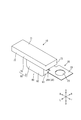
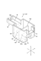
- FIG. 1 is a perspective view of a terminal module according to the first embodiment.
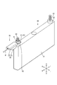
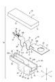
- Perspective view showing a state in which the terminal module is attached to a storage element
- the top view which shows the state which attached the terminal module to the electrical storage element.
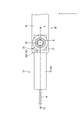
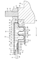
- Side view showing a state in which the terminal module is attached to the storage element
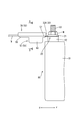
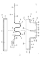
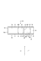
- Top view of voltage detection terminal Top view of lower protector The perspective view which shows the state which attached the terminal module which concerns on Embodiment 2 to the electrical storage element.
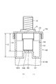
- Sectional view corresponding to the section of FIG. 5 of the terminal module Sectional view corresponding to the section of FIG. 6 of the terminal module
- FIGS. 1 to 10 A first embodiment of the technology disclosed in this specification will be described with reference to FIGS. 1 to 10.
- the present embodiment exemplifies the terminal module 10 connected to the power storage element 80.
- the U direction in FIGS. 1 and 2 is the upper direction
- the D direction is the lower direction
- the R direction is the right direction
- the L direction is the left direction.
- the F direction in FIGS. 1 and 2 will be described as the front and the B direction will be described as the rear.
- the electricity storage element 80 has a flat, substantially rectangular parallelepiped element body 81 in which an electricity storage element (not shown) is housed.
- the element body 81 has a pair of pedestals 82 at both ends in the front-rear direction, and bolt-shaped electrode terminals 83 protruding upward from the pedestal 82 are provided on the upper surface of the pedestal 82. ..
- the electrode terminal 83 is connected to a voltage detection terminal 20 described later of the terminal module 10. To connect the voltage detection terminal 20 to the electrode terminal 83, the voltage detection terminal 20 is assembled so that the electrode terminal 83 is inserted, and the nut N is tightened in the electrode terminal 83. Then, the electrode terminal 83 and the voltage detection terminal 20 are sandwiched between the nut N and the pedestal portion 82 to be electrically connected.
- the terminal module 10 includes a voltage detection terminal 20 for detecting the voltage of the storage element 80, and a protector 50 that houses a part of the voltage detection terminal 20. There is.
- the voltage detection terminal 20 is formed by processing a conductive metal plate material such as copper, copper alloy, aluminum, aluminum alloy, and stainless steel (SUS) by a press or the like.
- a conductive metal plate material such as copper, copper alloy, aluminum, aluminum alloy, and stainless steel (SUS)
- the voltage detection terminal 20 includes a terminal connecting portion 21 connected to the electrode terminal 83 of the storage element 80, an electric wire connecting portion 22 connected to the end of the electric wire W, and a terminal connecting portion. 21 and the wire connection part 22 and the connection part 30 which connects in the front-back direction.
- the terminal connecting portion 21 has a flat plate shape that is substantially rectangular in a plan view.
- the terminal connecting portion 21 is provided with an electrode insertion hole 23 penetrating in the plate thickness direction. By inserting the electrode terminal 83 of the storage element 80 into the electrode insertion hole 23, the terminal connecting portion 21 is connected to the electrode terminal 83. It can be assembled and electrically connected.
- the wire connecting portion 22 is arranged side by side behind the terminal connecting portion 21 and the connecting portion 30, and has a wire barrel 25 connected to the rear of the connecting portion 30 and an insulation barrel 26 connected to the rear of the wire barrel 25. is doing.
- the wire connecting portion 22 is connected to the end of the electric wire W by crimping the wire barrel 25 to the core wire W1 exposed from the insulating coating W2 at the end of the electric wire W, and crimping the insulation barrel 26 to the insulating coating W2. There is.
- the end of the electric wire W on the side opposite to the side connected to the voltage detection terminal 20 is connected to an ECU (Electronic Control Unit) not shown.
- the ECU has a microcomputer, an electronic element, and the like mounted therein, and has a well-known configuration having a function of detecting the voltage, current, temperature, and the like of the power storage element 80.
- the connecting portion 30 is formed in a plate shape having a uniform width in the front-rear direction, the front end portion 30A of the connecting portion 30 is connected to the rear edge of the terminal connecting portion 21, and the rear end portion 30B is connected to the front edge of the wire connecting portion 22.
- the terminal connection portion 21 and the electric wire connection portion 22 are connected in the front-rear direction by being connected to each other.
- the protector 50 is made of insulating synthetic resin. As shown in FIGS. 5 to 8 and 10, the protector 50 has a lower protector 51 in which the voltage detection terminal 20 is housed from above, and an upper protector 70 assembled to the lower protector 51 from above.
- the lower protector 51 is formed in a generally rectangular shape in plan view that is long in the front-rear direction, and includes a first accommodating portion 52 that accommodates the front end portion 30A of the connecting portion 30, a rear end portion 30B of the connecting portion 30, and the voltage detection terminal 20. It has the 2nd accommodating part 55 which accommodates the electric wire connection part 22.
- the first accommodating portion 52 is configured to include a first mounting wall 53 that is substantially rectangular in a plan view, and a pair of first side walls 54 that are erected on both lateral edges of the first mounting wall 53. And is open in the front-rear direction and upward.
- the front end portion 30A of the connecting portion 30 that extends straight rearward from the rear edge of the terminal connecting portion 21 can be mounted on the first mounting wall 53 from above, and the length of the first mounting wall 53 in the left-right direction can be increased.
- the length dimension is set to be slightly larger than the length dimension of the connecting portion 30 in the left-right direction.
- the second accommodating portion 55 includes a second mounting wall 56 that is substantially rectangular in a plan view, a pair of second side walls 57 that are erected on both lateral edges of the second mounting wall 56, and a second mounting wall.
- the second rear wall 58 is provided continuously with the rear end edge 56 and the rear end edges of the pair of second side walls 57, and is open forward and upward.
- the electric wire connecting portion 22 and the rear end portion 30B of the connecting portion 30 that extends straight forward from the front edge of the electric wire connecting portion 22 can be mounted from above.
- the height position of 56 in the up-down direction is substantially the same as the height position of the first mounting wall 53.
- the substantially same height includes the case where the second mounting wall 56 and the first mounting wall 53 have the same height, and the second mounting wall 56 and the first mounting wall 53 have the same height. Includes cases where the heights are recognized to be approximately the same even if the heights are different.
- the second rear wall 58 is formed with a wire drawing hole 58A for drawing out the electric wire W connected to the wire connecting portion 22 from the upper end of the second rear wall 58 so as to be recessed downward.
- the electric wire W is inserted into the electric wire drawing hole 58A, and the electric wire W is rearward from the electric wire drawing hole 58A. It is designed to be pulled out to.
- the upper protector 70 includes a ceiling wall 71 having a substantially rectangular shape in a plan view, a pair of upper side walls 72 extending downward from left and right ends of the ceiling wall 71, and a ceiling wall 71.
- the upper front wall 73 extends downward from the front end edge.
- the upper protector 70 is formed slightly larger in the front-rear, left-right direction than the lower protector 51.
- the upper front wall 73 has a dimension (length in the vertical direction) extending from the ceiling wall 71 set to be slightly shorter than the height dimension of the first housing portion 52 in the lower protector 51, and the upper protector 70 is lower.
- the insertion opening through which the front end portion 30A of the connecting portion 30 is inserted between the upper front wall 73 and the first mounting wall 53 of the first accommodating portion 52. 59 are formed.
- the connecting portion 30 in the voltage detection terminal 20 has a plurality of liquid drainage portions 31, and the lower protector 51 of the protector 50 has a plurality of liquid storage portions between the first storage portion 52 and the second storage portion 55. It has an accommodating portion 60 for accommodating the cut portion 31.
- the plurality of liquid draining parts 31 are continuous in the front-rear direction so as to connect the front end part 30A of the connecting part 30 and the rear end part 30B of the connecting part 30 in the front-rear direction. There is.
- Each liquid draining portion 31 is formed to have the same width dimension as the front end portion 30A and the rear end portion 30B of the connecting portion 30, and is bent downward from the front end portion 30A and extends downward in the gravity direction.
- the extending portion 32, the bent portion 33 that is folded back in an arc shape from the lower end edge of the first extending portion 32 toward the rear, and the opposite upper end edge of the bent portion 33 with respect to the gravity direction. It has the 2nd extension part 34 extended toward the upper part.
- first extension portion 32 and the second extension portion 34 are in a state of facing each other in the front-rear direction, and the bent portion 33 and the lower end edge that is the extension end portion of the first extension portion 32.
- the lower end edge which is the base end portion of the second extending portion 34 is connected in a bent state.
- a portion where the liquid draining portion 31 is continuous in the front-rear direction is a rear end edge which is a front end portion of the second extending portion 34 in the front liquid draining portion 31 and the first extending portion 32 in the rear liquid draining portion 31.
- the upper end position which is the apex of the connecting part 35 is connected to the upper end edge which is the base end part of the connecting part 35 by the connecting part 35 which is bent in an arc shape. It is set to almost the same position.
- each liquid draining portion 31 of the connecting portion 30 is arranged below the height position of the front end portion 30A and the rear end portion 30B of the connecting portion 30 in the direction of gravity and below the pedestal portion 82 of the element body 81. It is configured to meander up and down along the side surface 82A.
- the accommodating portion 60 is formed in a box shape that is larger in the up-down direction than the first accommodating portion 52 and the second accommodating portion 55. It has a bottom wall 61 that is substantially rectangular in a plan view and has the same width dimension as the width dimension of the first accommodation portion 52 and the second accommodation portion 55 in the left-right direction.
- a pair of side walls 62 is provided upright on both lateral edges of the bottom wall 61, and upper end surfaces 62A of the pair of side walls 62 have a first accommodating portion 52 and a second accommodating portion. It is flush with the upper end surface 51A of 55.
- the accommodating portion 60 is configured to project downward from the first accommodating portion 52 and the second accommodating portion 55, and the accommodating portion 60 is similar to the liquid draining portion 31 of the voltage detection terminal 20 in the element body 81. It is designed to be placed behind (sideways).
- the front wall 63 of the accommodating portion 60 extends downward from the rear end edge of the first mounting wall 53 of the first accommodating portion 52 and is continuous with the front end edge of the bottom wall 61, and the rear wall 64 of the accommodating portion 60 is
- the second accommodation wall 55 extends downward from the front end edge of the second mounting wall 56 and continues to the rear end edge of the bottom wall 61.
- the pair of side walls 62 of the housing portion 60 are connected to the first side wall 54 of the first housing portion 52 and the second side wall 57 of the second housing portion 55 so as to be flush with each other in the front-rear direction.
- the inside of the storage unit 60 is divided into a plurality of individual storage units 65 that individually store the plurality of liquid draining units 31.
- the plurality of individual accommodating portions 65 are arranged side by side so as to be continuous in the front-rear direction.
- the individual accommodation portions 65 adjacent to each other in the front-rear direction are separated from each other by a partition wall 60A extending in the left-right direction on the pair of side walls 62 of the accommodation portion 60.
- the rear wall 65B of the individual accommodating portion 65 arranged is formed, and the front wall 65F of the individual accommodating portion 65 arranged on the rear side is formed.
- the front wall 65F of the foremost individual housing portion 65 of the plurality of individual housing portions 65 constitutes the front wall 63 of the housing portion 60
- the rear wall 65B of the last individual housing portion 65 is the rear wall of the housing portion 60. 64 are configured.
- the side walls 65A on the left and right sides of the individual accommodating portions 65 that are adjacent to each other in the front-rear direction are connected in the front-rear direction to form the side walls 62 on the left and right sides of the accommodating portion 60.
- the bottom wall 61 of the housing portion 60 and the bent portion 33 of the liquid draining portion 31 are shown. And are vertically opposed to each other with a gap dimension L2 smaller than the thickness dimension L1 of the bottom wall 61.
- the front wall 65F of the individual accommodation portion 65 and the first extending portion 32 of the liquid draining portion 31 face each other in the front-rear direction, and the rear wall 65B of the individual accommodation portion 65 and the liquid draining portion.
- the gap dimension L3 between the front wall 65F of the individual accommodating portion 65 and the first extending portion 32 becomes larger than that of the individual accommodating portion 65.
- the first extending portion 32 and the second extending portion 34 are arranged in the individual accommodation portion 65 so as to be smaller than the gap dimension L4 between the wall 65B and the second extending portion 34.
- liquid such as water droplets may adhere to electrode terminals or the like to which the terminal module is connected.
- the temperature of the electrode terminal decreases, dew condensation occurs on the electrode terminal, so that the liquid adheres.
- the liquid adhering to the electrode terminal reaches the electric wire through the voltage detection terminal, the liquid may enter the voltage detector or the ECU through the electric wire and cause a problem.
- the terminal module 10 of the present embodiment has at least one of the voltage detection terminal 20 having the terminal connection portion 21 connected to the electrode terminal 83 and the electric wire connection portion 22 connected to the electric wire W, and at least one of the voltage detection terminals 20.
- the protector 50 has at least one 31, and the protector 50 has an accommodating portion 60 that accommodates the liquid draining portion 31 and stores the liquid that has propagated through the first extending portion 32.
- the liquid attached to the electrode terminal 83 travels from the terminal connecting portion 21 to the first extending portion 32 of the liquid draining portion 31 and from the lower end portion of the first extending portion 32. It falls and is stored in the accommodation unit 60. This can prevent the liquid from reaching the electric wire connecting portion 22. As a result, it is possible to prevent the liquid from penetrating the electric wire W and invading other devices to cause a problem.
- the liquid draining part 31 includes the second extending part 34 extending upward, which is the opposite direction to the downward direction which is the gravity direction, and the extending end edge of the first extending part 32. And a bending portion 33 that connects the lower end edge that is the lower end edge that is the base end portion of the second extending portion 34 in a bent state, and the accommodating portion 60 has a gap between the bending portion 33. It has a bottom wall 61 facing the bent portion 33 in the state of having.
- the liquid that has propagated through the first extending portion 32 is attracted to the gap between the bent portion 33 of the liquid draining portion 31 and the bottom wall 61 of the accommodating portion 60 by surface tension, and the liquid easily stays in the accommodating portion 60. Therefore, it is possible to further suppress the liquid from reaching the electric wire connecting portion 22.
- the electrode terminal 83 of the present embodiment is provided on the element body 81 of the electricity storage element 80, and the first extending portion 32 extends along the side surface 82A of the pedestal portion 82 of the element body 81.
- the length dimension of the first extending portion 32 can be set to be larger than that in the case where the first extending portion is arranged above the element body. That is, since the liquid can be guided to the position away from the electric wire connecting portion 22 by the first extending portion 32, it is possible to further suppress the liquid from reaching the electric wire connecting portion 22.
- the terminal module 10 is attached as compared with the case where the housing portion is arranged above the element body of the power storage element. Further, it is possible to prevent the height dimension of the entire electricity storage device 80 from increasing. That is, it is very effective when the height dimension is limited in the space where the electricity storage element 80 is arranged. Further, in the present embodiment, since the plurality of liquid draining portions 31 are provided between the terminal connecting portion 21 and the electric wire connecting portion 22, it is possible to suppress the liquid from reaching the electric wire connecting portion 22. .
- the storage unit 60 of the present embodiment has the individual storage unit 65 that individually stores the plurality of liquid draining parts 31, the liquid that has dropped from each liquid draining part 31 travels along the bottom wall 61 and is not transferred. It is possible to prevent the liquid draining part 31 from reaching.
- the individual housing portion 65 of the present embodiment has a front wall (first side wall) 65F extending along the first extending portion 32 and a rear wall (second side wall) 65B extending along the second extending portion 34.
- the gap dimension L3 between the first extending portion 32 and the front wall 65F is set smaller than the gap dimension L4 between the second extending portion 34 and the rear wall 65B. ..
- the liquid adhering to the liquid draining part 31 is attracted to the gap between the first extending part 32 and the front wall 65F by the surface tension, and the liquid can be quickly drawn into the individual accommodating part 65.
- the gap dimension L4 between the second extending portion 34 and the rear wall 65B is larger than the gap dimension L3 between the first extending portion 32 and the front wall 65F, the individual accommodating portion 65. It is possible to suppress the liquid drawn into the second extension portion 34 from reaching the electric wire connection portion 22 side.
- the protector 150 according to the second embodiment is different from the protector 50 according to the first embodiment in that the width dimension of the housing portion 60 in the left-right direction is changed, and the configurations, actions, and effects common to the first embodiment are duplicated. The description is omitted. Further, the same reference numerals are used for the same configurations as the first embodiment.
- the accommodating portion 160 of the lower protector 151 of the second embodiment has a liquid reservoir main body 166 extending along the direction in which the terminal connecting portion 21 and the electric wire connecting portion 22 are arranged, and a direction intersecting the extending direction of the liquid reservoir main body 166. And a pair of auxiliary liquid reservoirs 167 projecting from the liquid reservoir body 166 in the orthogonal direction. Further, the upper protector 170 has a shape in which a substantially central portion in the front-rear direction is projected in the left-right direction so as to match the housing portion 160.
- the liquid reservoir body 166 is set to have substantially the same width dimension as the width dimension of the first accommodating portion 52 and the second accommodating portion 55 in the left-right direction. Therefore, the auxiliary liquid reservoir 167 has a form protruding in the left-right direction from the first container 52 and the second container 55.
- the auxiliary liquid reservoir portion 167 projects below the liquid reservoir main body portion 166, and the bottom wall 167A of the auxiliary liquid reservoir portion 167 is It is set at a position one step lower than the bottom wall 166A of 166. Therefore, the vertical depth dimension L5 of the auxiliary liquid reservoir 167 is set larger than the vertical depth dimension L6 of the liquid reservoir body 166. In other words, the internal space of the container 160 of this embodiment, and thus the individual container 165, is larger than that in the case where the auxiliary liquid reservoir is not provided.
- the accommodating portion 160 has the auxiliary liquid reservoir portion 167 protruding in the left-right direction and the vertical direction from the liquid reservoir main body portion 166, as compared with the case where the auxiliary reservoir portion is not provided, A large amount of liquid that drops along the first extending part 32 can be stored in the housing part 160, and it is possible to further suppress liquid from reaching the wire connecting part 22 side along the second extending part 34. You can do it.
- the technology disclosed in this specification is not limited to the embodiments described by the above description and the drawings, and includes various aspects such as the following.
- the terminal connection portion 21 of the voltage detection terminal 20 and the electrode terminal 83 are fastened by the nut N and the pedestal portion 82.
- the configuration is not limited to this, and the terminal connection portion may be configured to be connected to the electrode terminal by laser welding, ultrasonic welding, resistance welding, or the like.
- the voltage detection terminal 20 connected to the electrode terminal 83 is shown as an example.
- the present invention is not limited to this, and the technique disclosed in the present specification may be applied to a bus bar terminal that connects electrode terminals of adjacent power storage elements.
- the voltage detection terminal 20 is connected to the electrode terminal 83 of the storage element 80.
- the configuration is not limited to this, and the voltage detection terminal may be connected to an electrode terminal such as a capacitor.
- the liquid attached to the electrode terminal 83 is a water droplet.
- the liquid that adheres to the electrode terminals may be a liquid other than water drops, such as an electrolytic solution.
- the storage portions 60 and 160 are configured to store the liquid that has flowed down from the liquid draining portion 31.
- the present invention is not limited to this, and the storage portion may be provided with a discharge hole for guiding the liquid flowing down from the liquid draining portion to a safe external area.
- Terminal module 20 Voltage detection terminal (an example of "terminal") 21: terminal connection part 22: electric wire connection part 32: first extension part 31: liquid draining part 33: bent part 34: second extension part 50: protector 60: housing part 61: bottom wall 65: individual housing part 65B : Rear wall (an example of "second side wall") 65F: Front wall (an example of "first side wall”) 80: Electric storage element 81: Element body 83: Electrode terminal 166: Liquid reservoir body 167: Auxiliary liquid reservoir L2: Gap L3: Gap dimension L4 between first extension and first side wall: Second extension Dimension W Between the Portion and the Second Side Wall: Electric Wire
Landscapes
- Chemical & Material Sciences (AREA)
- Chemical Kinetics & Catalysis (AREA)
- Electrochemistry (AREA)
- General Chemical & Material Sciences (AREA)
- Physics & Mathematics (AREA)
- General Physics & Mathematics (AREA)
- Engineering & Computer Science (AREA)
- Power Engineering (AREA)
- Microelectronics & Electronic Packaging (AREA)
- Connection Of Batteries Or Terminals (AREA)
- Battery Mounting, Suspending (AREA)
- Electric Double-Layer Capacitors Or The Like (AREA)
Priority Applications (2)
| Application Number | Priority Date | Filing Date | Title |
|---|---|---|---|
| CN201980074024.2A CN112970082B (zh) | 2018-11-22 | 2019-11-01 | 端子模块 |
| US17/295,285 US11982712B2 (en) | 2018-11-22 | 2019-11-01 | Terminal module |
Applications Claiming Priority (2)
| Application Number | Priority Date | Filing Date | Title |
|---|---|---|---|
| JP2018-219042 | 2018-11-22 | ||
| JP2018219042A JP6981394B2 (ja) | 2018-11-22 | 2018-11-22 | 端子モジュール |
Publications (1)
| Publication Number | Publication Date |
|---|---|
| WO2020105398A1 true WO2020105398A1 (ja) | 2020-05-28 |
Family
ID=70773174
Family Applications (1)
| Application Number | Title | Priority Date | Filing Date |
|---|---|---|---|
| PCT/JP2019/042998 Ceased WO2020105398A1 (ja) | 2018-11-22 | 2019-11-01 | 端子モジュール |
Country Status (4)
| Country | Link |
|---|---|
| US (1) | US11982712B2 (enExample) |
| JP (1) | JP6981394B2 (enExample) |
| CN (1) | CN112970082B (enExample) |
| WO (1) | WO2020105398A1 (enExample) |
Families Citing this family (3)
| Publication number | Priority date | Publication date | Assignee | Title |
|---|---|---|---|---|
| JP7531781B2 (ja) | 2020-05-19 | 2024-08-13 | 株式会社リコー | p型半導性を有する金属酸化物粒子、それを用いた電子デバイス及び電子デバイスの製造方法、並びに画像形成装置 |
| CN117083763A (zh) * | 2021-04-07 | 2023-11-17 | 日本汽车能源株式会社 | 电池组 |
| JP7601704B2 (ja) * | 2021-04-30 | 2024-12-17 | 矢崎総業株式会社 | 電圧検知ユニット |
Citations (5)
| Publication number | Priority date | Publication date | Assignee | Title |
|---|---|---|---|---|
| JP2015005473A (ja) * | 2013-06-24 | 2015-01-08 | 住友電気工業株式会社 | ブスバーおよびブスバーの製造方法 |
| JP2015035322A (ja) * | 2013-08-08 | 2015-02-19 | 矢崎総業株式会社 | バスバモジュール |
| JP2017059468A (ja) * | 2015-09-18 | 2017-03-23 | 株式会社オートネットワーク技術研究所 | 端子付き電線、及び配線モジュール |
| WO2017047371A1 (ja) * | 2015-09-16 | 2017-03-23 | 株式会社オートネットワーク技術研究所 | 端子及び配線モジュール |
| WO2017047372A1 (ja) * | 2015-09-16 | 2017-03-23 | 株式会社オートネットワーク技術研究所 | 端子及び配線モジュール |
Family Cites Families (5)
| Publication number | Priority date | Publication date | Assignee | Title |
|---|---|---|---|---|
| JP3613445B2 (ja) * | 1999-05-18 | 2005-01-26 | 矢崎総業株式会社 | バッテリ接続プレート |
| JP2010257764A (ja) * | 2009-04-24 | 2010-11-11 | Toyota Motor Corp | 端子および電池 |
| JP2010257762A (ja) * | 2009-04-24 | 2010-11-11 | Toyota Motor Corp | 端子および電池 |
| JP5462813B2 (ja) | 2011-02-09 | 2014-04-02 | 矢崎総業株式会社 | バスバモジュール |
| JP6297922B2 (ja) * | 2014-05-23 | 2018-03-20 | 株式会社デンソー | 電池パック |
-
2018
- 2018-11-22 JP JP2018219042A patent/JP6981394B2/ja active Active
-
2019
- 2019-11-01 CN CN201980074024.2A patent/CN112970082B/zh active Active
- 2019-11-01 WO PCT/JP2019/042998 patent/WO2020105398A1/ja not_active Ceased
- 2019-11-01 US US17/295,285 patent/US11982712B2/en active Active
Patent Citations (5)
| Publication number | Priority date | Publication date | Assignee | Title |
|---|---|---|---|---|
| JP2015005473A (ja) * | 2013-06-24 | 2015-01-08 | 住友電気工業株式会社 | ブスバーおよびブスバーの製造方法 |
| JP2015035322A (ja) * | 2013-08-08 | 2015-02-19 | 矢崎総業株式会社 | バスバモジュール |
| WO2017047371A1 (ja) * | 2015-09-16 | 2017-03-23 | 株式会社オートネットワーク技術研究所 | 端子及び配線モジュール |
| WO2017047372A1 (ja) * | 2015-09-16 | 2017-03-23 | 株式会社オートネットワーク技術研究所 | 端子及び配線モジュール |
| JP2017059468A (ja) * | 2015-09-18 | 2017-03-23 | 株式会社オートネットワーク技術研究所 | 端子付き電線、及び配線モジュール |
Also Published As
| Publication number | Publication date |
|---|---|
| US11982712B2 (en) | 2024-05-14 |
| JP6981394B2 (ja) | 2021-12-15 |
| CN112970082A (zh) | 2021-06-15 |
| US20220013871A1 (en) | 2022-01-13 |
| JP2020087650A (ja) | 2020-06-04 |
| CN112970082B (zh) | 2023-06-13 |
Similar Documents
| Publication | Publication Date | Title |
|---|---|---|
| JP6372620B2 (ja) | 端子及び配線モジュール | |
| JP7307213B2 (ja) | 電池モジュール | |
| JP6204876B2 (ja) | 温度センサの取付構造 | |
| WO2020105398A1 (ja) | 端子モジュール | |
| JP5609825B2 (ja) | 電池接続ユニット及び電源装置 | |
| JP5875107B2 (ja) | 電池接続体 | |
| JP4445819B2 (ja) | 電気接続箱 | |
| JP6699464B2 (ja) | 接続モジュール | |
| JP6508345B2 (ja) | 端子及び配線モジュール | |
| JPWO2020241145A5 (enExample) | ||
| CN119092298A (zh) | 电容器 | |
| JP6317898B2 (ja) | バスバモジュール | |
| JP6575869B2 (ja) | フィルムコンデンサ | |
| US10984952B2 (en) | Capacitor | |
| JP7042412B2 (ja) | 接続モジュールおよび蓄電モジュール | |
| CN101133536B (zh) | 电连接盒 | |
| JP5080326B2 (ja) | 電子部品の端子接続構造及び電動パワーステアリング装置のコントロールユニット構造並びに電子部品の端子接続方法 | |
| JP6158635B2 (ja) | バスバモジュール | |
| JP7145462B2 (ja) | コンデンサ | |
| JP4277054B1 (ja) | 蛍光管ホルダおよびその製造方法 | |
| JP2022037943A (ja) | 電池配線モジュール | |
| JP2015019470A (ja) | 端子接続具、及び電気接続箱 | |
| JP2006302669A (ja) | アダプタ |
Legal Events
| Date | Code | Title | Description |
|---|---|---|---|
| 121 | Ep: the epo has been informed by wipo that ep was designated in this application |
Ref document number: 19887418 Country of ref document: EP Kind code of ref document: A1 |
|
| NENP | Non-entry into the national phase |
Ref country code: DE |
|
| 122 | Ep: pct application non-entry in european phase |
Ref document number: 19887418 Country of ref document: EP Kind code of ref document: A1 |