WO2020105243A1 - レーザ溶接方法及び積層体 - Google Patents
レーザ溶接方法及び積層体Info
- Publication number
- WO2020105243A1 WO2020105243A1 PCT/JP2019/033973 JP2019033973W WO2020105243A1 WO 2020105243 A1 WO2020105243 A1 WO 2020105243A1 JP 2019033973 W JP2019033973 W JP 2019033973W WO 2020105243 A1 WO2020105243 A1 WO 2020105243A1
- Authority
- WO
- WIPO (PCT)
- Prior art keywords
- laser
- path
- laminated body
- outer peripheral
- state
- Prior art date
- Legal status (The legal status is an assumption and is not a legal conclusion. Google has not performed a legal analysis and makes no representation as to the accuracy of the status listed.)
- Ceased
Links
Images

Classifications
-
- B—PERFORMING OPERATIONS; TRANSPORTING
- B23—MACHINE TOOLS; METAL-WORKING NOT OTHERWISE PROVIDED FOR
- B23K—SOLDERING OR UNSOLDERING; WELDING; CLADDING OR PLATING BY SOLDERING OR WELDING; CUTTING BY APPLYING HEAT LOCALLY, e.g. FLAME CUTTING; WORKING BY LASER BEAM
- B23K26/00—Working by laser beam, e.g. welding, cutting or boring
- B23K26/20—Bonding
- B23K26/21—Bonding by welding
Definitions
- the present invention relates to a laser welding method and a laminated body.
- laser spot welding is performed using a laser welding device.
- a plurality of metal plates are melted by laser light and then cooled to weld the plurality of metal plates (for example, Patent Document 1).
- the metal plate has a melting point or higher so as to form a first welding pattern capable of preheating the entire area of the welding target portion in a region inside the outer periphery of the welding target portion having a substantially circular outer shape in the metal plate.
- a first welding pattern capable of preheating the entire area of the welding target portion in a region inside the outer periphery of the welding target portion having a substantially circular outer shape in the metal plate.
- Patent Document 1 when the internal space is closed by the welded portion, the air in the closed space is heated at the time of welding to expand and pressurize the welded portion, thereby damaging the welded portion. It may end up. Further, in Patent Document 1, an edge protruding upward is generated in the inner portion of the welded portion, and the appearance and paintability of the laminated body after welding are poor and the quality is low.
- the present invention has been made in view of such circumstances, and an object of the present invention is to provide a laser welding method and a laminated body capable of preventing damage to a welded portion and improving the quality of the laminated body after welding.
- the laser welding method of the present invention is a laser welding method for irradiating and joining a laser beam to a laminated body formed by stacking a plurality of metal plates, and adjusting the output of the laser beam so that the laminated body can be melted.
- the first step of irradiating along the outer peripheral path that extends so as to surround a predetermined portion of the laminated body in the state of being opened and at least a part of which is open, and the laser beam is performed after the first step.
- the laser light is adjusted to be capable of melting the laminated body, and is extended to surround a predetermined portion of the laminated body, and at least a part of the outer peripheral path is opened. Since it has the 1st process of irradiating along, air between each metal plate (gap) of a layered product can be discharged from the above-mentioned opened part. This prevents the air in the gap between the metal plates of the laminated body from thermally expanding inside the welded portion of the laminated body and damaging the welded portion.
- a second step of irradiating the laser beam along the inner peripheral portion of the outer peripheral path in a state where the output is adjusted so as to melt without passing through the uppermost metal plate of the laminated body Therefore, the edge generated on the inner peripheral portion of the welded portion welded in the first step can be melted by the laser light irradiated in the second step.
- the appearance and paintability of the laminated body after welding can be improved, and the quality can be improved, as compared with those having an edge.
- the laser is provided by a first path extending along an inner peripheral portion of the outer peripheral path and a second path extending in an opposite direction to the first peripheral path along an inner peripheral portion of the outer peripheral path. It is preferable to irradiate with light.
- the laminated body of the present invention is a laminated body constituted by laminating a plurality of metal plates, and is a laser-welded laminated body, and the laser welding is performed on the lower surface of the lowermost metal plate of the plurality of metal plates.
- the welded portion extends so as to surround a predetermined portion of the lowermost metal plate and is formed in a shape in which at least a part thereof is opened, and the upper surface of the uppermost metal plate of the plurality of metal plates is formed. Then, the welded portion is formed in a recessed shape.
- the laminated body of the present invention since the welded portion is formed in a recessed shape on the upper surface of the uppermost metal plate of the plurality of metal plates, an edge protruding upward is formed in the welded portion.
- the appearance and paintability of the laminated body after welding can be improved and the quality can be improved as compared with the case where there is an edge.
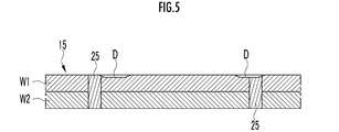
- FIG. 5 is a cross-sectional view taken along line VV showing the laminated body that is irradiated with the laser light in the second state after being welded with the laser light in the first state.
- a laser welding apparatus 10 that executes the laser welding method of the present embodiment includes a laser irradiation unit 11 that emits a laser beam L, and a laser control unit 12 that controls the driving of the laser irradiation unit 11. Equipped with.
- the laser welding apparatus 10 joins the laminated body 15 that is used in a vehicle and that includes a first metal plate W1 and a second metal plate W2.
- the laminated body 15 is placed on a supporting jig (not shown), and is joined by the laser welding device 10 while being sandwiched by the supporting jig and a clamper (not shown).
- the laser welding apparatus 10 and the laminated body 15 are schematically illustrated.
- the laser irradiation unit 11 includes a laser oscillator 11a.
- the laser irradiation unit 11 also includes, for example, an X-axis galvanometer mirror that scans the laser light from the laser oscillator 11a in the X-axis direction, and a Y-axis galvanometer that scans the laser light scanned by the X-axis galvanometer mirror in the Y-axis direction.
- a mirror and a condenser lens are provided.
- the laser irradiation unit 11 also includes a known galvano scanner 11b having an X-axis motor that rotates an X-axis galvanometer mirror, a Y-axis motor that rotates a Y-axis galvanometer mirror, and a control driver (neither shown). With.
- the structure of the galvano scanner 11b can be changed as appropriate.
- the galvano scanner 11b rotates the X-axis galvanometer mirror and the Y-axis galvanometer mirror to an appropriate angle by using the X-axis motor and the Y-axis motor whose rotation angles are controlled by the control driver, and irradiates the laser light to a target position. ..
- the laser irradiation unit 11 is attached to the first arm 17a of the robot 17.
- the robot 17 is, for example, a multi-axis, multi-joint type robot, and is provided with first to fourth arms 17a to 17d in order from the tip.
- the robot 17 is provided with a plurality of motors (not shown) that drive the arms 17a to 17d, and the drive is controlled by the robot controller 18.
- the root of the robot 17 is supported on the ground or a pedestal (not shown) fixed to the ground.
- the robot controller 18 drives a plurality of motors of the robot 17 to drive the arms 17a to 17d to control the position and the direction of the laser irradiation unit 11 attached to the arm 17a, and the laser irradiation unit 11 Are moved to the joint portion of the laminated body 15.
- the robot controller 18 drives a plurality of motors of the robot 17 to drive the arms 17a to 17d so that the laser irradiation unit 11 is moved by a support jig and a clamper. Control is performed so as to maintain substantially the same distance from the upper surface of the sandwiched laminated body 15 (upper surface of the first metal plate W1) (hereinafter, referred to as same distance control).
- the robot controller 18 drives the arms 17a to 17d to move the laser irradiation unit 11 to the right in FIGS. 1 to 5 at a constant speed while performing the same distance control described above.
- the laser control unit 12 operates the laser oscillator 11a and the galvano scanner 11b of the laser irradiation unit 11 that is moved to the right in FIGS.
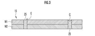
- the laser light L in the first state whose output (energy) is adjusted so that the fifteenth first metal plate W1 and the second metal plate W2 can be melted is irradiated (first step).
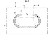
- the laser control unit 12 extends the laser light L in the first state into a substantially arc-shaped outer peripheral route OR that extends so as to surround the predetermined portion 15a of the stacked body 15 and is at least partially opened. Irradiate along (first step).
- the arrow on the outer peripheral route OR indicates the moving direction of the route.
- the laser light L in the first state is irradiated along the outer peripheral route OR.
- the outer peripheral route OR has a portion in which the direction of the route is leftward in FIGS. 2 and 3, and in this portion, the distance from the laser irradiation unit 11 moving to the right to the outer peripheral route OR becomes large, and the laser in the first state It is also necessary to change the irradiation direction of the light L.
- the laser control unit 12 operates the galvano scanner 11b to change the scanning directions of the X-axis galvanometer mirror and the Y-axis galvanometer mirror to change the irradiation direction of the laser light L in the first state.
- the laser light L in the first state is controlled to be emitted along the outer peripheral route OR.
- the laser beam L in the first state is irradiated along the outer peripheral path OR, and the bead 25 (hatched portion in FIGS. 2 and 4) having the shape of the outer peripheral path OR surrounding the predetermined portion 15a is formed.
- the laminated body 15 is joined.
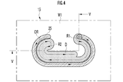
- the laser control unit 12 operates the laser oscillator 11a and the galvano scanner 11b of the laser irradiation unit 11 which are moved to the right in FIGS. 4 and 5 at a constant speed. Then, the laser beam L in the second state whose output is adjusted so as to be melted without penetrating the uppermost first metal plate W1 of the laminated body 15 is irradiated (second step). In the second step, the laser control unit 12 directs the laser light L in the second state to the first route R1 extending along the inner circumferential portion of the outer circumferential route OR and the outer route OR in the opposite direction to the first route R1. Irradiation is performed on the second route R2 extending along the inner peripheral portion.
- the galvano scanner 11b is operated to change the scanning directions of the X-axis galvanometer mirror and the Y-axis galvanometer mirror to change the irradiation direction of the laser light L in the second state.
- the irradiation is controlled to be performed along the first route R1 and the second route R2.
- the portion of the surface of the first metal plate W1 that is irradiated with the laser light L in the second state (the portion that is thinly painted in FIG. 4) is melted and becomes the depressed shape D.
- the irradiation range of the laser beam in the second state may include at least the first route R1, and the outer peripheral route OR and the first route R1 may be continuous or may have a gap.
- the portion where the bead 25 is formed (the portion where the first metal plate W1 and the second metal plate W2 are welded) has a substantially arc shape (a peripheral route OR) in which a part is opened.
- the air in the gap between the first metal plate W1 and the second metal plate W2 can be discharged from the open portion.
- the air in the gap between the first metal plate W1 and the second metal plate W2 thermally expands inside the portion where the first metal plate W1 and the second metal plate W2 are welded, and the bead 25 is damaged.
- the laser light L in the second state is irradiated on the first route R1 extending along the inner circumferential portion of the outer circumferential route OR (bead 25) (second step).
- the output of the laser light L in the second state is adjusted so as to melt without passing through the uppermost first metal plate W1 of the stacked body 15.
- the inner peripheral portion of the bead 25 (hatched portion) is overlapped with the portion irradiated with the laser light L in the second state (portion marked with thin ink in FIG. 4). Therefore, as shown in FIG. 5, the edge E formed on the inner peripheral portion of the bead 25 can be melted by the laser light L in the second state, and a new edge is not generated. Thereby, the appearance and paintability of the laminated body 15 after welding can be improved, and the quality can be improved.
- the laser control unit 12 moves at predetermined intervals in the laminated body 15. Control is performed so as to perform the first step and the second step. Thereby, as shown in FIG. 1, the laminated body 15 is spot-welded at a predetermined interval and firmly joined.
- the outer peripheral route OR is formed in a substantially arc shape, but it may be a partially open outer peripheral route, and may be a polygonal shape or an elliptical shape.
- the laser light in the second state is emitted through the first route R1 and the second route R2, but at least the first route R1 may be emitted.
- the outer peripheral route OR and the first route R1 may be continuous with each other or may have a gap therebetween.
Landscapes
- Physics & Mathematics (AREA)
- Optics & Photonics (AREA)
- Engineering & Computer Science (AREA)
- Plasma & Fusion (AREA)
- Mechanical Engineering (AREA)
- Sealing Battery Cases Or Jackets (AREA)
- Laser Beam Processing (AREA)
Abstract
Description
次に、レーザ溶接装置10による第1,第2金属板W1,W2のレーザ溶接方法について説明する。
Claims (3)
- 複数の金属板を重ねて構成された積層体にレーザ光を照射して接合するレーザ溶接方法であって、
前記レーザ光を、前記積層体を溶融可能に出力調整された状態で、前記積層体の所定部分を囲むように延び、且つ、少なくとも一部が開放された外周経路に沿って照射する第1工程と、
前記第1工程の後に行われ、前記レーザ光を、前記積層体の最上層の前記金属板を貫通させずに溶融するように出力調整された状態で、前記外周経路の内周部分に沿って照射する第2工程と、
を備えることを特徴とするレーザ溶接方法。 - 請求項1に記載のレーザ溶接方法において、
前記第2工程では、前記外周経路の内周部分に沿って延びる第1経路、及び前記第1経路とは逆向きで前記外周経路の内周部分に沿って延びる第2経路で前記レーザ光を照射することを特徴とするレーザ溶接方法。 - 複数の金属板が重ねられて構成され、レーザ溶接された積層体であって、
前記複数の金属板のうちの最下層の前記金属板の下面では、前記レーザ溶接された溶接部分は、前記最下層の金属板の所定部分を囲むように延び、且つ、少なくとも一部が開放された形状で形成され、
前記複数の金属板のうちの最上層の前記金属板の上面では、前記溶接部分は、窪んだ形状で形成されていることを特徴とする積層体。
Priority Applications (3)
| Application Number | Priority Date | Filing Date | Title |
|---|---|---|---|
| PH1/2021/550755A PH12021550755B1 (en) | 2018-11-20 | 2019-08-29 | Laser welding method, and laminate |
| MYPI2021002719A MY205432A (en) | 2018-11-20 | 2019-08-29 | Laser welding method, and laminate |
| JP2020558101A JP7105912B2 (ja) | 2018-11-20 | 2019-08-29 | レーザ溶接方法及び積層体 |
Applications Claiming Priority (2)
| Application Number | Priority Date | Filing Date | Title |
|---|---|---|---|
| JP2018217556 | 2018-11-20 | ||
| JP2018-217556 | 2018-11-20 |
Publications (1)
| Publication Number | Publication Date |
|---|---|
| WO2020105243A1 true WO2020105243A1 (ja) | 2020-05-28 |
Family
ID=70773886
Family Applications (1)
| Application Number | Title | Priority Date | Filing Date |
|---|---|---|---|
| PCT/JP2019/033973 Ceased WO2020105243A1 (ja) | 2018-11-20 | 2019-08-29 | レーザ溶接方法及び積層体 |
Country Status (4)
| Country | Link |
|---|---|
| JP (1) | JP7105912B2 (ja) |
| MY (1) | MY205432A (ja) |
| PH (1) | PH12021550755B1 (ja) |
| WO (1) | WO2020105243A1 (ja) |
Cited By (1)
| Publication number | Priority date | Publication date | Assignee | Title |
|---|---|---|---|---|
| JP2023169769A (ja) * | 2022-05-17 | 2023-11-30 | 日本発條株式会社 | レーザ溶接継手及びレーザ溶接方法 |
Citations (1)
| Publication number | Priority date | Publication date | Assignee | Title |
|---|---|---|---|---|
| WO2018169033A1 (ja) * | 2017-03-17 | 2018-09-20 | 本田技研工業株式会社 | 溶接部材及びレーザ溶接方法 |
-
2019
- 2019-08-29 MY MYPI2021002719A patent/MY205432A/en unknown
- 2019-08-29 WO PCT/JP2019/033973 patent/WO2020105243A1/ja not_active Ceased
- 2019-08-29 PH PH1/2021/550755A patent/PH12021550755B1/en unknown
- 2019-08-29 JP JP2020558101A patent/JP7105912B2/ja active Active
Patent Citations (1)
| Publication number | Priority date | Publication date | Assignee | Title |
|---|---|---|---|---|
| WO2018169033A1 (ja) * | 2017-03-17 | 2018-09-20 | 本田技研工業株式会社 | 溶接部材及びレーザ溶接方法 |
Cited By (1)
| Publication number | Priority date | Publication date | Assignee | Title |
|---|---|---|---|---|
| JP2023169769A (ja) * | 2022-05-17 | 2023-11-30 | 日本発條株式会社 | レーザ溶接継手及びレーザ溶接方法 |
Also Published As
| Publication number | Publication date |
|---|---|
| JP7105912B2 (ja) | 2022-07-25 |
| PH12021550755A1 (en) | 2021-10-11 |
| MY205432A (en) | 2024-10-21 |
| JPWO2020105243A1 (ja) | 2021-09-27 |
| PH12021550755B1 (en) | 2024-03-22 |
Similar Documents
| Publication | Publication Date | Title |
|---|---|---|
| CN105899323B (zh) | 激光焊接方法以及激光焊接装置 | |
| CN109202287B (zh) | 激光焊接方法及激光焊接装置 | |
| JP5551792B2 (ja) | 2つの金属構成部材の溶接方法、および2つの金属構成部材を有する接合構成体 | |
| US9737960B2 (en) | Laser-based lap welding of sheet metal components using laser induced protuberances to control gap | |
| JP6299136B2 (ja) | 鋼板のレーザー溶接方法およびレーザー溶接装置 | |
| WO2017177410A1 (en) | Laser spot welding of overlapping aluminum workpieces | |
| JP2005088585A (ja) | レーザー光線による部品の接合方法及び装置 | |
| WO2008133063A1 (ja) | 重ね合わせワークのレーザ溶接方法 | |
| JP2009183970A (ja) | レーザ溶接方法、レーザ溶接装置、および溶接部材 | |
| WO2020246504A1 (ja) | レーザ溶接装置及びそれを用いたレーザ溶接方法 | |
| JPH0732180A (ja) | 亜鉛めっき鋼板のレーザ溶接方法 | |
| JP5446334B2 (ja) | レーザ溶接装置、およびレーザ溶接方法 | |
| JP2008238209A (ja) | レーザ溶接方法及びレーザ溶接装置 | |
| JP4915315B2 (ja) | レーザ溶接方法及びレーザ溶接装置 | |
| JP2019000906A (ja) | 重ね溶接方法 | |
| JP2008126241A (ja) | レーザ溶接方法およびその装置 | |
| WO2020105243A1 (ja) | レーザ溶接方法及び積層体 | |
| JP2007253179A (ja) | レーザ溶接方法 | |
| CN115768587B (zh) | 激光焊接方法以及激光焊接装置 | |
| JP7213440B2 (ja) | レーザ溶接方法及びレーザ溶接装置 | |
| WO2022075209A1 (ja) | レーザ溶接方法及びレーザ溶接装置 | |
| WO2014203489A1 (ja) | 外装缶封口方法及び外装缶封口装置 | |
| JPH06155058A (ja) | レーザ重合せ溶接方法 | |
| JP2009148794A (ja) | レーザ溶接方法およびレーザ溶接システム | |
| JP2020078818A (ja) | アルミニウム合金板の重ね隅肉溶接方法 |
Legal Events
| Date | Code | Title | Description |
|---|---|---|---|
| 121 | Ep: the epo has been informed by wipo that ep was designated in this application |
Ref document number: 19886469 Country of ref document: EP Kind code of ref document: A1 |
|
| ENP | Entry into the national phase |
Ref document number: 2020558101 Country of ref document: JP Kind code of ref document: A |
|
| WWE | Wipo information: entry into national phase |
Ref document number: 2101002239 Country of ref document: TH |
|
| NENP | Non-entry into the national phase |
Ref country code: DE |
|
| 122 | Ep: pct application non-entry in european phase |
Ref document number: 19886469 Country of ref document: EP Kind code of ref document: A1 |