WO2020105202A1 - 情報処理装置 - Google Patents
情報処理装置Info
- Publication number
- WO2020105202A1 WO2020105202A1 PCT/JP2019/014670 JP2019014670W WO2020105202A1 WO 2020105202 A1 WO2020105202 A1 WO 2020105202A1 JP 2019014670 W JP2019014670 W JP 2019014670W WO 2020105202 A1 WO2020105202 A1 WO 2020105202A1
- Authority
- WO
- WIPO (PCT)
- Prior art keywords
- area
- auxiliary
- data
- unit
- read
- Prior art date
- Legal status (The legal status is an assumption and is not a legal conclusion. Google has not performed a legal analysis and makes no representation as to the accuracy of the status listed.)
- Ceased
Links
Images



Classifications
-
- G—PHYSICS
- G06—COMPUTING OR CALCULATING; COUNTING
- G06F—ELECTRIC DIGITAL DATA PROCESSING
- G06F3/00—Input arrangements for transferring data to be processed into a form capable of being handled by the computer; Output arrangements for transferring data from processing unit to output unit, e.g. interface arrangements
- G06F3/06—Digital input from, or digital output to, record carriers, e.g. RAID, emulated record carriers or networked record carriers
- G06F3/0601—Interfaces specially adapted for storage systems
- G06F3/0602—Interfaces specially adapted for storage systems specifically adapted to achieve a particular effect
- G06F3/0614—Improving the reliability of storage systems
- G06F3/0616—Improving the reliability of storage systems in relation to life time, e.g. increasing Mean Time Between Failures [MTBF]
-
- G—PHYSICS
- G06—COMPUTING OR CALCULATING; COUNTING
- G06F—ELECTRIC DIGITAL DATA PROCESSING
- G06F3/00—Input arrangements for transferring data to be processed into a form capable of being handled by the computer; Output arrangements for transferring data from processing unit to output unit, e.g. interface arrangements
- G06F3/06—Digital input from, or digital output to, record carriers, e.g. RAID, emulated record carriers or networked record carriers
-
- G—PHYSICS
- G06—COMPUTING OR CALCULATING; COUNTING
- G06F—ELECTRIC DIGITAL DATA PROCESSING
- G06F3/00—Input arrangements for transferring data to be processed into a form capable of being handled by the computer; Output arrangements for transferring data from processing unit to output unit, e.g. interface arrangements
- G06F3/06—Digital input from, or digital output to, record carriers, e.g. RAID, emulated record carriers or networked record carriers
- G06F3/0601—Interfaces specially adapted for storage systems
- G06F3/0628—Interfaces specially adapted for storage systems making use of a particular technique
- G06F3/0646—Horizontal data movement in storage systems, i.e. moving data in between storage devices or systems
- G06F3/0647—Migration mechanisms
-
- G—PHYSICS
- G06—COMPUTING OR CALCULATING; COUNTING
- G06F—ELECTRIC DIGITAL DATA PROCESSING
- G06F3/00—Input arrangements for transferring data to be processed into a form capable of being handled by the computer; Output arrangements for transferring data from processing unit to output unit, e.g. interface arrangements
- G06F3/06—Digital input from, or digital output to, record carriers, e.g. RAID, emulated record carriers or networked record carriers
- G06F3/0601—Interfaces specially adapted for storage systems
- G06F3/0668—Interfaces specially adapted for storage systems adopting a particular infrastructure
- G06F3/0671—In-line storage system
- G06F3/0673—Single storage device
- G06F3/0674—Disk device
- G06F3/0676—Magnetic disk device
-
- G—PHYSICS
- G11—INFORMATION STORAGE
- G11B—INFORMATION STORAGE BASED ON RELATIVE MOVEMENT BETWEEN RECORD CARRIER AND TRANSDUCER
- G11B20/00—Signal processing not specific to the method of recording or reproducing; Circuits therefor
- G11B20/10—Digital recording or reproducing
-
- G—PHYSICS
- G11—INFORMATION STORAGE
- G11B—INFORMATION STORAGE BASED ON RELATIVE MOVEMENT BETWEEN RECORD CARRIER AND TRANSDUCER
- G11B20/00—Signal processing not specific to the method of recording or reproducing; Circuits therefor
- G11B20/10—Digital recording or reproducing
- G11B20/18—Error detection or correction; Testing, e.g. of drop-outs
Definitions
- the embodiment of the present invention relates to an information processing device.
- the cause of the hard-to-read area is the magnetic material peeling off of the platter of the hard disk drive or the adherence of foreign matter, the damage may spread if the normal data is hard to read and the operation continues. There is. Further, if the number of alternative sectors increases due to continuous operation, the allowable amount of the alternative area may be exceeded, causing slower processing operations, frequent error occurrences, freezes, abnormal noise, etc. .. In the case of a hard disk drive, it is not generally used from the beginning to use the entire capacity, but it is used with unused areas left unused, and it is operated gradually to use the unused areas. There is. Therefore, if it is possible to provide an information processing device that can manage data using an unused area in a hard disk drive, it is possible to effectively prevent data loss, prevent damage from expanding, and improve reliability as a hard disk drive. It is meaningful.
- the information processing device includes, for example, an area setting unit, an information acquisition unit, a copy processing unit, and an output unit.
- the area setting unit executes the data read / write processing for the first area, which is a part of the entire area, and when the data read / write processing for the first area fails, the unused area in the first area is not used.
- the information acquisition unit acquires history information in which the number of alternative sectors generated in the first area is recorded.
- the copy processing unit causes the data in the first area to be copied to any one of the unused auxiliary areas of the auxiliary areas when the increased number of the alternative sectors is equal to or greater than a predetermined threshold, and the auxiliary area for which copying has been completed is deleted.
- a read / write process is executed by the hard disk drive as the first area.
- the output unit outputs usage information indicating the usage status of the auxiliary area.
- FIG. 1 is an explanatory diagram exemplarily and schematically showing a hard disk drive and a built-in platter to which the information processing apparatus according to the embodiment is applicable.
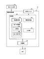
- FIG. 2 is a block diagram exemplarily and schematically showing the details of the configuration of the information processing apparatus according to the embodiment.
- FIG. 3 is an exemplary flowchart illustrating a processing flow when setting the auxiliary area in the information processing apparatus according to the embodiment.
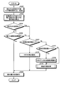
- FIG. 4 is an exemplary flowchart illustrating a processing flow including a warning process in the information processing apparatus according to the embodiment.
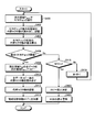
- FIG. 5 is an exemplary flowchart explaining the details of the area switching process in the flowchart of FIG.
- FIG. 6 is an exemplary flowchart illustrating details of another area switching process in the flowchart of FIG.
- FIG. 1 is an exemplary schematic diagram of a hard disk drive 10 (hereinafter, referred to as HDD 10) and a platter 12 incorporated therein to which an information processing apparatus according to an embodiment is applicable.
- the platter 12 is a storage medium component in which a fine magnetic material is uniformly applied or vapor-deposited on the surface of a disk-shaped substrate made of aluminum alloy, glass, ceramics or the like.
- the platter 12 has a support hole 12a formed in the center thereof fixed to a rotary shaft (spindle) (not shown), and rotates at high speed by rotational driving of the rotary shaft.
- the platter 12 is housed in a case 10 a of the HDD 10 in a hermetically sealed state together with a swing arm 14 having a magnetic head 14 a at its tip, a drive mechanism having a spindle, and the like.
- the magnetic head 14a executes a data writing operation and a data reading operation with respect to the platter 12 while being floated by several nm from the platter 12 which rotates at a high speed.
- a recording layer is formed on the front and back surfaces of the platter 12, or a multi-layer structure in which a plurality of platters 12 are arranged with a gap in the rotation axis direction is used. There is also.
- the magnetic head 14a (swing arm 14) is arranged for each recording layer.
- the HDD 10 executes a data read / write process with respect to the first area of the entire storage area in which accessible data has been recorded. Further, in the HDD 10, as a result of repeated reading and writing of data during operation, there may be an area where it is difficult to read data in the first area. In this case, the HDD 10 adjusts the start timing of the reading process, adjusts the bias current of the magnetic head 14a, etc., and retries many times to read the data. After the read / write processing of the data has failed, if the reading is successful as a result of the retry, the HDD 10 generates an alternative sector for moving the data to an unused area in the first area.
- the HDD 10 avoids data loss by continuing the data read / write processing in the alternative sector.
- the information processing apparatus of the present embodiment moves all the data to a part of the unused second area other than the first area (one of the auxiliary areas obtained by dividing the second area), and Read / write processing is executed with the area as the first area.
- a partial area of the total available capacity for example, an area of a few tenths to a few tenths of the total capacity is, for example, application data. It is used as an initial use area that stores numerical data and the like. Then, the remaining area can be used as an auxiliary area that enables access while avoiding loss of application data and numerical data stored in the first area.
- the entire area can be used as a storage area in which arbitrary data can be stored at any time.
- FIG. 2 is a block diagram exemplarily and schematically showing the details of the configuration of the information processing apparatus 16 capable of executing the area switching processing according to the embodiment.
- the information processing device 16 may be configured by hardware and connected to the HDD 10 via a predetermined interface to execute the area switching processing as described above, or a system including the HDD 10 (for example, a personal computer). It may be realized by the software included in the above-mentioned area switching processing.
- FIG. 2 as an example, a case where the information processing device 16 is configured by hardware and is connected to the HDD 10 will be described.
- the information processing device 16 is a display / input device in which the user inputs the setting conditions of the area switching processing and displays various information output from the information processing device 16, for example, a warning.
- the section 18 is connected via a predetermined interface.
- the display / input section 18 may be omitted and the functions of the personal computer side may be used.
- the information processing device 16 moves the data in the first area to an unused auxiliary area where damage does not exist (or is unlikely to exist) as described above, switches the access area, and continues the read / write processing.
- a control unit 20, a storage unit 22 and the like are included in order to realize the function to be performed.
- the changeover switch 24 that switches whether or not the unused auxiliary area (second area) for moving the data in the first area where the read / write processing is currently executable is set (for example, A dip switch or toggle switch) is connected to the information processing device 16.
- the second area can be used as a storage area for other data, and the HDD 10 can be used in the conventional way.
- the area switching function of the present embodiment may be switched between valid and invalid according to a switching command input using the display / input unit 18.
- the control unit 20 includes an area setting unit 26, an information acquisition unit 28, a copy processing unit 30, an output unit 32, and the like.
- the copy processing unit 30 also includes a comparison unit 30a, a copy execution unit 30b, and the like.
- the storage unit 22 can store the input information input by the user via the display / input unit 18 and the like, and the information (the number of alternative sectors) acquired by the information acquisition unit 28.
- the storage unit 22 refers to a threshold value (a region switching threshold value, an R / W check threshold value, and the like, which will be described later) that the copy execution unit 30b refers to when the comparison unit 30a determines whether or not to copy data in the HDD 10. It is possible to store the copy performance (area switching count H) in the copy execution unit 30b.
- the area setting unit 26 sets an area including a used area in which data is already stored in the HDD 10 and an area for a substitute sector when a read failure occurs. This is the first area. Further, the area setting unit 26 sets an unused area other than the first area as the second area. Then, the area setting unit 26 sets at least one, for example, n auxiliary areas corresponding to the capacity of the first area in the second area. For example, it is assumed that the capacity of the entire area 34 of the platter 12 of the HDD 10 shown in FIG. 1 is 1 TB (terabyte).
- an area in which application data, numerical data, image data, and the like are stored and a use area already secured as an area for a substitute sector are defined as a first area 34a.
- the first area 34a for example, 100 GB (gigabytes) of the entire area 34 of the platter 12 is set as the used area.
- the remaining 900 GB becomes the second area 34b.
- the area setting unit 26 When setting the plurality of auxiliary areas 36 in the second area 34b of the platter 12 of the HDD 10, the area setting unit 26, for example, as shown in FIG. Set to do.
- the moving distance of the magnetic head 14a due to the switching of the region can be shortened.
- the region where the region switching is performed to be a region adjacent in the radial direction, the movement amount of the magnetic head 14a can be minimized.
- the area (first area 34a) initially secured as the used area is the outermost circumference of the platter 12, but the first area 34a is accessible for read / write processing.
- the auxiliary area 36 to which the data has moved is regarded as the first area 34a in the subsequent processing. Note that the setting of the auxiliary area 36 by the area setting unit 26 at the time of initial setting does not substantially set the area on the platter 12, but the position information when the data is recorded on the platter 12 side is processed by the information processing device 16 This area is virtually set on the information processing apparatus 16 side so that the information processing apparatus 16 can recognize it.
- the number n of auxiliary regions 36 set by the region setting unit 26 may be set so that the capacity of the auxiliary region 36 at the time of setting is equal to or larger than the capacity of the first region 34a. Therefore, the area setting unit 26 may automatically determine the set number n according to the usage status of the HDD 10. In another embodiment, for example, the user uses the display / input unit 18 to specify the capacity of the auxiliary area 36 or set the number n of the auxiliary areas 36 so that the capacity is equal to or larger than the capacity of the first area 34a at the time of initial setting. The area may be set by designating.
- the information acquisition unit 28 acquires necessary information from the history information recorded in the HDD 10 according to the operating state.
- the history information it is possible to use SMART (Self-Monitoring, Analysis and Reporting Technology) information that the HDD 10 collects during operation as a standard function.
- the SMART information is, for example, information such as the frequency of occurrence of errors such as the number of occurrences of alternative sectors and the worst recording, the number of times the power is turned on / off, the time when the power is turned on, the seek time of the magnetic head 14a, and the like. Is included.
- the information acquisition unit 28 reads and acquires information regarding the number of alternative sectors from the SMART information from the HDD 10 and records the information in the storage unit 22.
- the information acquisition unit 28 reads the number of alternative sectors from the HDD 10 when the area setting unit 26 sets the auxiliary area 36, and stores it in the storage unit 22, for example. In addition, the information acquisition unit 28 reads the latest number of alternative sectors from the HDD 10 in the storage unit 22 at a predetermined processing cycle, for example, while the HDD 10 is operating. In this case, the number of alternative sectors already stored in the storage unit 22 is set to the previous value, and the number of newly read alternative sectors is stored in the storage unit 22 as the latest value. Therefore, the storage unit 22 stores the previous value and the latest value.
- the copy processing unit 30 causes the information acquisition unit 28 to transfer the data in the first area 34a to any one of the unused auxiliary areas 36 among the auxiliary areas 36 when the increased number of the acquired alternative sectors is equal to or larger than a predetermined threshold value.
- the HDD 10 is caused to execute the copying process.
- the comparison unit 30a calculates the difference between the previous value and the latest value of the number of alternative sectors stored in the storage unit 22 by the information acquisition unit 28. That is, the number of alternative sectors mainly generated in the first area 34a due to the read / write process of the HDD 10 between the storage of the previous number of alternative sectors and the storage of the latest number of alternative sectors can be calculated. Then, the comparison unit 30a compares the difference with the area switching threshold stored in the storage unit 22 in advance.
- the area switching threshold is a threshold determined in advance by a test or the like. For example, the relationship between the number of alternative sectors generated in the same area of the platter 12 (for example, the first area 34a that is currently accessible) and the processing speed delay of the HDD 10 or the frequency of error occurrence is acquired by a test or the like. .. Then, the area switching threshold value is determined based on the number of times of occurrence of the allowable number of alternative sectors that can be considered that the HDD 10 can operate normally. The area switching threshold value is preferably set in consideration of the margin value.
- the comparison unit 30a determines that the difference between the alternative sectors is equal to or greater than the area switching threshold, that is, in the currently accessible first area 34a, the occurrence of more alternative sectors causes a risk of data loss.
- the copy executing unit 30b copies the data in the first area 34a to the unused auxiliary area 36.
- the copy executing unit 30b increments the area switching count H indicating the copy result by “+1” and records the value in the storage unit 22. ..
- the copy executing unit 30b before copying the data in the first area 34a to the auxiliary area 36, writes the auxiliary area 36 to be copied, for example, in the auxiliary area 36 adjacent to the currently accessible first area 34a.
- a read / write check process (R / W check), which is a function of the HDD 10, may be executed. If the number of read / write errors (for example, the number of alternative sectors) is less than a predetermined threshold (R / W check threshold) as a result of the R / W check, for example, the copy execution unit 30b determines that the number of read / write errors is less than 10 times. In this case, the auxiliary area 36 may be made to copy the data in the first area 34a.
- the copy executing unit 30b confirms in advance the possibility of occurrence of alternative sectors in the auxiliary area 36, and the number of alternative sectors exceeds the area switching threshold early (areas to other auxiliary areas 36). Exclude the auxiliary area 36 that may need to be switched) from the data migration target. As a result, the copy executing unit 30b can reduce the risk of data loss, reduce the delay in the processing operation of the HDD 10 and reduce the frequency of errors, and contribute to the improvement of the reliability of the HDD 10.
- the copy executing unit 30b regardless of whether or not the number of alternative sectors is increased, for example, when the user receives a copy request command input using the display / input unit 18 or the like, the data in the first area 34a is displayed.
- the auxiliary area 36 may be forcibly copied to any one of the unused auxiliary areas 36. For example, even when the user feels an abnormality in the HDD 10 based on past experience, data can be moved, and the reliability of the HDD 10 can be improved. In addition, even if data movement is required for operational reasons or the like, it is possible to quickly move the data, which can contribute to improvement of usability of the HDD 10.
- the output unit 32 outputs the usage information indicating the usage status of the auxiliary area 36 to, for example, the display / input unit 18 to display the usage information.
- the number of times the copy executing unit 30b can copy the data of the first area 34a to the unused auxiliary area 36 is also finite. Therefore, when the copy execution unit 30b has already issued the copy instruction to the last unused auxiliary area 36, that is, the number H of times of area switching has reached the set number n of the auxiliary areas 36 set by the area setting unit 26. In this case, the output unit 32 outputs a stop warning that recommends that the currently operating HDD 10 be promptly stopped and measures taken.
- the user can avoid the loss of data by performing the replacement work of the HDD 10 (the work of migrating the data to another HDD 10) according to the output stop warning. Further, when the number H + 1 of area switching reaches the set number n of the auxiliary areas 36 set by the area setting unit 26, that is, the number of the remaining unused auxiliary areas 36 after the area switching is 1 by the output unit 32. In such a case, a data saving recommendation warning of the HDD 10 may be output in advance.
- the output unit 32 may perform information display according to the number of remaining unused auxiliary areas 36, for example, countdown display of the number of remaining unused auxiliary areas 36.
- FIG. 2 is a functional block diagram exemplifying the functions necessary for the information processing device 16. If the same functions can be realized, the functions may be integrated or separated as appropriate.
- the area setting unit 26 causes the platter 12 to support the platter 12.
- the setting of the area 36 is executed (S100).
- the area setting unit 26 uses the capacity of the used area secured as the first area 34a in the HDD 10 input from the display / input unit 18 (for areas storing application data, numerical data, image data, etc., and for alternative sectors).
- the auxiliary area 36 is determined based on the capacity of the first area 34a and the capacity of the second area 34b other than the first area 34a.
- the area setting unit 26 sets n auxiliary areas 36 corresponding to the capacity of the first area 34a in the second area 34b.
- the user may input the set number n using the display / input unit 18, or the capacity of the first area 34a is acquired from the HDD 10 and the second area 34b is set.
- the number n of possible settings may be calculated.
- the information acquisition unit 28 reads the number of alternative sectors of the entire area 34 of the platter 12 from the SMART information stored in the HDD 10 (S102).
- the information acquisition unit 28 stores the read current number of alternative sectors in a predetermined area of the storage unit 22 (S104).
- the control unit 20 permits the HDD 10 to start read / write processing in the first area 34a (S106).
- FIG. 4 is an exemplary flowchart illustrating a flow of processing including a warning processing in the information processing device 16.
- the flowchart of FIG. 4 is repeatedly executed at a predetermined processing cycle while the information processing device 16 is operating.
- the process of the flowchart of FIG. 4 is performed, for example, when the HDD 10 is powered on, when the system connected to the HDD 10 is powered on, the time set by a timer or the like is displayed / input by the user. It can also be executed when a maintenance command is input to optimize the HDD 10 using the unit 18.
- the information acquisition unit 28 reads the number of alternative sectors of the entire area 34 of the platter 12 in the current state from the SMART information stored in the HDD 10 and stores it as the latest value of the number of alternative sectors.
- the data is stored in the unit 22 (S200).
- the comparison unit 30a reads the number of alternative sectors (previous value) of the auxiliary area 36 stored in the storage unit 22 and the current number of alternative sectors (latest value) stored in S200, and calculates the difference between them. Yes (S202).
- the comparison unit 30a confirms whether there is an interrupt process for executing a compulsory switching request to the auxiliary region 36, and when there is no interrupt process (No in S204), the difference calculated in S204 and the region read from the storage unit 22. A comparison with the switching threshold value is performed (S206). The interrupt processing request can be made using the display / input unit 18, for example. If the comparison unit 30a determines that the difference is smaller than the area switching threshold value (Yes in S206) as a result of the comparison, at the present stage, the number of occurrences of the alternative sector is that the read / write processing in the currently accessible first area 34a is continued. However, it is determined that no problem will occur. As a result, the control unit 20 outputs to the HDD 10 a command permitting execution of read / write processing in the HDD 10 (S208).
- the copy execution unit 30b stores in the storage unit 22. It is confirmed whether the stored number H of times of area switching has reached the set number n of the auxiliary areas 36 (S210). When the number H of times of area switching has reached the set number n of the auxiliary areas 36 (Yes in S210), there is no more unused auxiliary area 36 in the platter 12. In such a case, the output unit 32 outputs a stop warning recommending that the currently operating HDD 10 be stopped immediately (S212). In this case, it is unlikely that data loss will occur immediately in the currently accessible first area 34a.
- control unit 20 outputs to the HDD 10 a command permitting execution of read / write processing in the HDD 10 (S208), and ends this flow once.
- the user executes the replacement work of the HDD 10 (the work of migrating the data to another HDD 10) according to the output stop warning, thereby surely avoiding the data loss which may occur in the near future. can do.
- the copy execution unit 30b sets “1” to the number H of region switching stored in the storage unit 22. It is added, and it is confirmed whether the number H + 1 of area switching has reached the set number n of the auxiliary area 36 (S214). That is, it is confirmed whether or not the remaining unused auxiliary area 36 is "1".
- the output unit 32 gives a preliminary warning of saving the data of the HDD 10. Is output (S216).
- the copy executing unit 30b executes the area switching process for copying all the data in the first area 34a to the unused auxiliary area 36 (S218).
- the evacuation recommendation warning when the evacuation recommendation warning is output, it means that one unused auxiliary area 36 remains, and the copy of data to the auxiliary area 36 can be surely executed. That is, there is still room before the HDD 10 needs to be replaced promptly. The user can prepare for the replacement work including securing a new HDD 10 according to the output evacuation recommendation warning, and can avoid data loss reliably and with a sufficient margin.
- the copy execution unit 30b copies all the data in the currently accessible first area 34a to the unused auxiliary area 36 (S300). For example, in FIG. 1, all the data is copied to the auxiliary area 36 that is radially adjacent to the first area 34a.
- the first area 34a that is currently accessible is referred to as an area P (M) .
- the unused adjacent auxiliary area 36 is defined as an area P (M + 1) .
- M is a subscript for identifying an area in the platter 12, and in FIG.
- the information acquisition unit 28 reads the number of alternative sectors of the entire area 34 of the platter 12 from the SMART information stored in the HDD 10 after copying (S302).
- the information acquisition unit 28 stores the number of read-out alternative sectors after copying in a predetermined area of the storage unit 22 (S304).
- the copy execution section 30b in order to record the results obtained by copying the entire data area P (M + 1) in the region P (M), and adds "1" to the area switching times H (S306), the flow Ends once.
- FIG. 6 is an exemplary flowchart illustrating the flow of another area switching process.
- read / write check processing (R / W check) is executed in advance for the area where data is to be copied, and when the number of read / write errors (the number of alternative sectors) is less than a predetermined number,
- the auxiliary area 36 (area P (M + 1) ) is made to execute data copy of the first area 34a (area P (M) ).
- the copy execution unit 30b executes the R / W check in the area P (M + 1) , which is the next area to be copied (S400). Subsequently, the information acquisition unit 28 reads the number of alternative sectors of the entire area 34 of the platter 12 after the R / W check from the SMART information stored in the HDD 10 and stores it in the storage unit 22 (S402). Then, the copy executing unit 30b calculates the difference between the number of alternative sectors before the R / W check stored in the storage unit 22 and the number of the alternative sectors after the R / W check stored in S402 (S404). Then, the copy execution unit 30b compares the difference calculated in S404 with the R / W check threshold value read from the storage unit 22 (S406).
- Comparing section 30a the result of the comparison, the difference ⁇ If it is determined that the R / W check threshold (Yes in S406), thereby copying the entire data area P (M) to the R / W Checked region P (M + 1) ( S408). In other words, it is determined that even if the data is copied to the area P (M + 1) , the number of alternative sectors immediately exceeds the area switching threshold and the copy must be made again in another auxiliary area 36.
- the copy execution unit 30b causes the HDD 10 to copy data.
- the information acquisition unit 28 reads the number of alternative sectors of the entire area 34 of the platter 12 from the SMART information stored in the HDD 10 after copying (S410).
- the information acquisition unit 28 stores the read number of alternative sectors after copying in a predetermined area of the storage unit 22 (S412).
- the copy execution unit 30b records the result of copying the data of the region P (M) to the region P (M + 1) (the result of copying the data of the first region 34a to the auxiliary region 36), and performs the number of region switching times. "1" is added to H (S414), and this flow is once ended.
- the process proceeds to S208, the control unit 20 outputs a command for permitting execution of the read / write processing in the HDD 10 to the HDD 10, and ends the flow of FIG. 4 once.
- the HDD 10 stop warning is output in S422
- the user replaces the HDD 10 (operation of transferring data to another HDD 10) in accordance with the stop warning as in the case of outputting the stop warning in S212. ), It is possible to avoid data loss.
- the possibility of occurrence of alternative sectors in the auxiliary area 36 is confirmed in advance, and the number of alternative sectors may exceed the area switching threshold at an early stage (area switching to another auxiliary area 36).
- the risk of data loss can be reduced, and the reliability of the HDD 10 can be improved.
- the information processing device 16 is configured by hardware, but a processing module that executes the same function on a CPU of a system (for example, a personal computer) or the like to which the HDD 10 is connected. May be realized.
- the software for realizing the information processing device 16 can be realized by acquiring the software via a storage medium or a communication line and installing it in the CPU, and the same effect can be obtained.
Landscapes
- Engineering & Computer Science (AREA)
- Theoretical Computer Science (AREA)
- Human Computer Interaction (AREA)
- Physics & Mathematics (AREA)
- General Engineering & Computer Science (AREA)
- General Physics & Mathematics (AREA)
- Signal Processing (AREA)
- Signal Processing For Digital Recording And Reproducing (AREA)
- Debugging And Monitoring (AREA)
Abstract
Description
Claims (5)
- 全領域のうち一部の領域である第1領域に対するデータの読み書き処理を実行するとともに、前記第1領域内のデータの読み書き処理に失敗した場合に、前記第1領域内の未使用の領域に前記データを移動させる代替セクタを生成し、当該代替セクタで前記データの読み書き処理を実行するハードディスクドライブに対して、前記第1領域以外の未使用の第2領域に前記第1領域の容量に対応する少なくとも一つの補助領域を設定する領域設定部と、
前記第1領域において生成された前記代替セクタの数が記録された履歴情報を取得する情報取得部と、
前記読み書き処理に伴う前記代替セクタの増加数が所定の閾値以上の場合に前記第1領域内のデータを前記補助領域のうち未使用のいずれか一つの前記補助領域にコピーさせて、コピーが完了した前記補助領域を前記第1領域として読み書き処理を前記ハードディスクドライブに実行させるコピー処理部と、
前記補助領域の利用状態を示す利用情報を出力する出力部と、
を備える、情報処理装置。 - 前記領域設定部は、前記補助領域の設定の有無を切り替える切替スイッチの状態にしたがい前記補助領域の設定の有無を決定する、請求項1に記載の情報処理装置。
- 前記コピー処理部は、前記代替セクタの増加数が前記閾値未満の場合において、コピー要求指令を受け付けた場合、前記第1領域内のデータを前記補助領域のうち未使用のいずれか一つにコピーさせて、前記補助領域を前記第1領域として読み書き処理を実行させる、請求項1または請求項2に記載の情報処理装置。
- 前記コピー処理部は、前記コピーを実行させるのに先立ち、コピー予定の前記補助領域に対してリードライトチェック処理を実行させて、リードライトエラーの数が所定の閾値未満の場合に、前記データのコピーを実行させる、請求項1から請求項3のいずれか1項に記載の情報処理装置。
- 前記領域設定部は、前記第2領域に複数の前記補助領域を設定する場合、前記ハードディスクドライブのプラッタに対して周方向に延びるトラックを最小単位として径方向に設定する、請求項1から請求項4のいずれか1項に記載の情報処理装置。
Priority Applications (3)
| Application Number | Priority Date | Filing Date | Title |
|---|---|---|---|
| SG11202008730UA SG11202008730UA (en) | 2018-11-22 | 2019-04-02 | Information processing device |
| CN201980011112.8A CN111670428B (zh) | 2018-11-22 | 2019-04-02 | 信息处理装置 |
| KR1020207033310A KR20210002571A (ko) | 2018-11-22 | 2019-04-02 | 정보 처리 장치 |
Applications Claiming Priority (2)
| Application Number | Priority Date | Filing Date | Title |
|---|---|---|---|
| JP2018219621A JP6668445B1 (ja) | 2018-11-22 | 2018-11-22 | 情報処理装置 |
| JP2018-219621 | 2018-11-22 |
Publications (1)
| Publication Number | Publication Date |
|---|---|
| WO2020105202A1 true WO2020105202A1 (ja) | 2020-05-28 |
Family
ID=70000675
Family Applications (1)
| Application Number | Title | Priority Date | Filing Date |
|---|---|---|---|
| PCT/JP2019/014670 Ceased WO2020105202A1 (ja) | 2018-11-22 | 2019-04-02 | 情報処理装置 |
Country Status (6)
| Country | Link |
|---|---|
| JP (1) | JP6668445B1 (ja) |
| KR (1) | KR20210002571A (ja) |
| CN (1) | CN111670428B (ja) |
| SG (1) | SG11202008730UA (ja) |
| TW (1) | TWI715040B (ja) |
| WO (1) | WO2020105202A1 (ja) |
Families Citing this family (1)
| Publication number | Priority date | Publication date | Assignee | Title |
|---|---|---|---|---|
| KR200499272Y1 (ko) | 2023-06-12 | 2025-06-18 | 송용권 | 건설현장의 그늘막 설치용 스프링 스트랩 |
Citations (6)
| Publication number | Priority date | Publication date | Assignee | Title |
|---|---|---|---|---|
| JPS6022712A (ja) * | 1983-07-19 | 1985-02-05 | Nec Corp | 磁気デイスク装置 |
| JPH07111035A (ja) * | 1993-10-13 | 1995-04-25 | Matsushita Electric Ind Co Ltd | 情報記録再生装置 |
| JP2001222866A (ja) * | 2000-02-04 | 2001-08-17 | Nec Corp | 論理アドレス再割り当て方法およびデータ記憶システム並びに記録媒体 |
| JP2005115975A (ja) * | 2003-10-02 | 2005-04-28 | Toshiba Tec Corp | 情報処理装置 |
| JP2008310846A (ja) * | 2007-06-12 | 2008-12-25 | Nec Corp | 汎用サーバにおけるハードディスクドライブ故障の事前チェック装置、その方法及びそのプログラム |
| JP2010225229A (ja) * | 2009-03-23 | 2010-10-07 | Hitachi Computer Peripherals Co Ltd | ハードディスクドライブ管理装置及び方法 |
Family Cites Families (10)
| Publication number | Priority date | Publication date | Assignee | Title |
|---|---|---|---|---|
| JP3130258B2 (ja) * | 1996-10-25 | 2001-01-31 | インターナショナル・ビジネス・マシーンズ・コーポレ−ション | ディスク装置及びデータ・リアサイン方法 |
| JP2000020248A (ja) | 1998-06-26 | 2000-01-21 | Nippon Digital Kenkyusho:Kk | ディスクの障害回復方法、ディスクドライバおよび記録媒体 |
| US7962739B2 (en) * | 2008-02-25 | 2011-06-14 | Lenovo (Singapore) Pte. Ltd. | Recovering from hard disk errors that corrupt one or more critical system boot files |
| TW200947450A (en) * | 2008-05-09 | 2009-11-16 | A Data Technology Co Ltd | Storage system capable of data recovery and method thereof |
| CN101527142B (zh) * | 2009-04-17 | 2011-04-13 | 杭州华三通信技术有限公司 | 一种磁盘冗余阵列中数据的读写方法和设备 |
| TWI506642B (zh) * | 2012-12-07 | 2015-11-01 | Phison Electronics Corp | 記憶體修復方法、記憶體控制器與記憶體儲存裝置 |
| FR2999644B1 (fr) * | 2012-12-19 | 2015-03-13 | Electricite De France | Procede de commande d'une centrale thermique au moyen de soupapes reglantes |
| JP2017037626A (ja) | 2015-08-07 | 2017-02-16 | 株式会社Jvcケンウッド | 故障予測装置、故障予測方法及び故障予測プログラム |
| JP6424330B2 (ja) * | 2015-10-13 | 2018-11-21 | 株式会社アクセル | 情報処理装置、及び情報処理方法 |
| CN107037976B (zh) * | 2016-02-03 | 2020-03-20 | 株式会社东芝 | 存储装置及其工作方法 |
-
2018
- 2018-11-22 JP JP2018219621A patent/JP6668445B1/ja active Active
-
2019
- 2019-04-02 CN CN201980011112.8A patent/CN111670428B/zh active Active
- 2019-04-02 SG SG11202008730UA patent/SG11202008730UA/en unknown
- 2019-04-02 KR KR1020207033310A patent/KR20210002571A/ko not_active Ceased
- 2019-04-02 WO PCT/JP2019/014670 patent/WO2020105202A1/ja not_active Ceased
- 2019-05-17 TW TW108117009A patent/TWI715040B/zh active
Patent Citations (6)
| Publication number | Priority date | Publication date | Assignee | Title |
|---|---|---|---|---|
| JPS6022712A (ja) * | 1983-07-19 | 1985-02-05 | Nec Corp | 磁気デイスク装置 |
| JPH07111035A (ja) * | 1993-10-13 | 1995-04-25 | Matsushita Electric Ind Co Ltd | 情報記録再生装置 |
| JP2001222866A (ja) * | 2000-02-04 | 2001-08-17 | Nec Corp | 論理アドレス再割り当て方法およびデータ記憶システム並びに記録媒体 |
| JP2005115975A (ja) * | 2003-10-02 | 2005-04-28 | Toshiba Tec Corp | 情報処理装置 |
| JP2008310846A (ja) * | 2007-06-12 | 2008-12-25 | Nec Corp | 汎用サーバにおけるハードディスクドライブ故障の事前チェック装置、その方法及びそのプログラム |
| JP2010225229A (ja) * | 2009-03-23 | 2010-10-07 | Hitachi Computer Peripherals Co Ltd | ハードディスクドライブ管理装置及び方法 |
Also Published As
| Publication number | Publication date |
|---|---|
| SG11202008730UA (en) | 2020-10-29 |
| TWI715040B (zh) | 2021-01-01 |
| JP6668445B1 (ja) | 2020-03-18 |
| JP2020086863A (ja) | 2020-06-04 |
| TW202020650A (zh) | 2020-06-01 |
| CN111670428A (zh) | 2020-09-15 |
| KR20210002571A (ko) | 2021-01-08 |
| CN111670428B (zh) | 2023-07-28 |
Similar Documents
| Publication | Publication Date | Title |
|---|---|---|
| JP4886877B2 (ja) | 記録媒体制御装置、及びその方法 | |
| US7925828B2 (en) | Magnetic disk drive refreshing data written to disk and data refreshment method applied to magnetic disk drive | |
| JP2008243269A (ja) | ディスク・ドライブ装置及びそのデータの再書き込み方法 | |
| US8291190B2 (en) | Disk drive including a host interface supporting different sizes of data sectors and method for writing data thereto | |
| JP2009020986A (ja) | ディスク・ドライブ装置及びディスク・ドライブ装置において不揮発性半導体メモリ領域上のデータを管理するテーブルを保存する方法 | |
| US20200294540A1 (en) | Magnetic disk device and method | |
| KR100413018B1 (ko) | 대체 섹터의 할당 방법, 데이터 판독 방법, 디스크드라이브 장치 및 오디오 비쥬얼 데이터의 판독 기록 장치 | |
| US20060077726A1 (en) | Data transfer method, storage apparatus and computer-readable storage medium | |
| JP3860967B2 (ja) | リードの自動交替方法及びこれを用いた磁気ディスク装置 | |
| JP6867591B2 (ja) | ストレージ制御装置、ストレージ制御方法およびストレージ制御プログラム | |
| JP2008010113A (ja) | 磁気ディスク制御装置、磁気ディスク装置および読取り障害修復方法 | |
| JP4240496B2 (ja) | アクセス制御のための装置および方法 | |
| JP2003308644A (ja) | ディスク記憶装置及び同装置における代替セクタアクセス方法 | |
| JP6668445B1 (ja) | 情報処理装置 | |
| JP6171616B2 (ja) | ストレージ制御装置、及びストレージ制御プログラム | |
| JP4672454B2 (ja) | 記憶装置 | |
| JP5621801B2 (ja) | 磁気ディスク制御装置、磁気ディスク装置および磁気ディスク制御方法 | |
| WO2005045827A1 (ja) | 情報記録装置と情報記録方法とプログラムを記録した記録媒体 | |
| JP2007287208A (ja) | データ記憶装置及びそのエラー訂正方法 | |
| WO2005041186A1 (ja) | 情報記録装置と情報記録方法と記録媒体 | |
| JP2004030788A (ja) | 書換可能な記憶媒体における欠陥管理装置および欠陥管理方法 | |
| JP3150242B2 (ja) | ディスク装置 | |
| JPH03290873A (ja) | ディスク型記憶装置、ディスク型記憶装置の制御装置、及びディスク型記憶装置の制御方法 | |
| US20060294310A1 (en) | Write control method and storage apparatus | |
| US20230093769A1 (en) | Magnetic disk device |
Legal Events
| Date | Code | Title | Description |
|---|---|---|---|
| 121 | Ep: the epo has been informed by wipo that ep was designated in this application |
Ref document number: 19887404 Country of ref document: EP Kind code of ref document: A1 |
|
| ENP | Entry into the national phase |
Ref document number: 20207033310 Country of ref document: KR Kind code of ref document: A |
|
| NENP | Non-entry into the national phase |
Ref country code: DE |
|
| 122 | Ep: pct application non-entry in european phase |
Ref document number: 19887404 Country of ref document: EP Kind code of ref document: A1 |
|
| WWG | Wipo information: grant in national office |
Ref document number: 11202008730U Country of ref document: SG |
|
| WWP | Wipo information: published in national office |
Ref document number: 11202008730U Country of ref document: SG |