WO2020101010A1 - 車両用制動装置 - Google Patents
車両用制動装置 Download PDFInfo
- Publication number
- WO2020101010A1 WO2020101010A1 PCT/JP2019/044810 JP2019044810W WO2020101010A1 WO 2020101010 A1 WO2020101010 A1 WO 2020101010A1 JP 2019044810 W JP2019044810 W JP 2019044810W WO 2020101010 A1 WO2020101010 A1 WO 2020101010A1
- Authority
- WO
- WIPO (PCT)
- Prior art keywords
- storage unit
- power
- power storage
- piston
- driving force
- Prior art date
- Legal status (The legal status is an assumption and is not a legal conclusion. Google has not performed a legal analysis and makes no representation as to the accuracy of the status listed.)
- Ceased
Links
Images


Classifications
-
- B—PERFORMING OPERATIONS; TRANSPORTING
- B60—VEHICLES IN GENERAL
- B60T—VEHICLE BRAKE CONTROL SYSTEMS OR PARTS THEREOF; BRAKE CONTROL SYSTEMS OR PARTS THEREOF, IN GENERAL; ARRANGEMENT OF BRAKING ELEMENTS ON VEHICLES IN GENERAL; PORTABLE DEVICES FOR PREVENTING UNWANTED MOVEMENT OF VEHICLES; VEHICLE MODIFICATIONS TO FACILITATE COOLING OF BRAKES
- B60T11/00—Transmitting braking action from initiating means to ultimate brake actuator without power assistance or drive or where such assistance or drive is irrelevant
- B60T11/10—Transmitting braking action from initiating means to ultimate brake actuator without power assistance or drive or where such assistance or drive is irrelevant transmitting by fluid means, e.g. hydraulic
- B60T11/16—Master control, e.g. master cylinders
-
- B—PERFORMING OPERATIONS; TRANSPORTING
- B60—VEHICLES IN GENERAL
- B60T—VEHICLE BRAKE CONTROL SYSTEMS OR PARTS THEREOF; BRAKE CONTROL SYSTEMS OR PARTS THEREOF, IN GENERAL; ARRANGEMENT OF BRAKING ELEMENTS ON VEHICLES IN GENERAL; PORTABLE DEVICES FOR PREVENTING UNWANTED MOVEMENT OF VEHICLES; VEHICLE MODIFICATIONS TO FACILITATE COOLING OF BRAKES
- B60T11/00—Transmitting braking action from initiating means to ultimate brake actuator without power assistance or drive or where such assistance or drive is irrelevant
- B60T11/10—Transmitting braking action from initiating means to ultimate brake actuator without power assistance or drive or where such assistance or drive is irrelevant transmitting by fluid means, e.g. hydraulic
- B60T11/16—Master control, e.g. master cylinders
- B60T11/224—Master control, e.g. master cylinders with pressure-varying means, e.g. with two stage operation provided by use of different piston diameters including continuous variation from one diameter to another
-
- B—PERFORMING OPERATIONS; TRANSPORTING
- B60—VEHICLES IN GENERAL
- B60T—VEHICLE BRAKE CONTROL SYSTEMS OR PARTS THEREOF; BRAKE CONTROL SYSTEMS OR PARTS THEREOF, IN GENERAL; ARRANGEMENT OF BRAKING ELEMENTS ON VEHICLES IN GENERAL; PORTABLE DEVICES FOR PREVENTING UNWANTED MOVEMENT OF VEHICLES; VEHICLE MODIFICATIONS TO FACILITATE COOLING OF BRAKES
- B60T13/00—Transmitting braking action from initiating means to ultimate brake actuator with power assistance or drive; Brake systems incorporating such transmitting means, e.g. air-pressure brake systems
- B60T13/10—Transmitting braking action from initiating means to ultimate brake actuator with power assistance or drive; Brake systems incorporating such transmitting means, e.g. air-pressure brake systems with fluid assistance, drive, or release
- B60T13/12—Transmitting braking action from initiating means to ultimate brake actuator with power assistance or drive; Brake systems incorporating such transmitting means, e.g. air-pressure brake systems with fluid assistance, drive, or release the fluid being liquid
- B60T13/16—Transmitting braking action from initiating means to ultimate brake actuator with power assistance or drive; Brake systems incorporating such transmitting means, e.g. air-pressure brake systems with fluid assistance, drive, or release the fluid being liquid using pumps directly, i.e. without interposition of accumulators or reservoirs
- B60T13/18—Transmitting braking action from initiating means to ultimate brake actuator with power assistance or drive; Brake systems incorporating such transmitting means, e.g. air-pressure brake systems with fluid assistance, drive, or release the fluid being liquid using pumps directly, i.e. without interposition of accumulators or reservoirs with control of pump output delivery, e.g. by distributor valves
-
- B—PERFORMING OPERATIONS; TRANSPORTING
- B60—VEHICLES IN GENERAL
- B60T—VEHICLE BRAKE CONTROL SYSTEMS OR PARTS THEREOF; BRAKE CONTROL SYSTEMS OR PARTS THEREOF, IN GENERAL; ARRANGEMENT OF BRAKING ELEMENTS ON VEHICLES IN GENERAL; PORTABLE DEVICES FOR PREVENTING UNWANTED MOVEMENT OF VEHICLES; VEHICLE MODIFICATIONS TO FACILITATE COOLING OF BRAKES
- B60T13/00—Transmitting braking action from initiating means to ultimate brake actuator with power assistance or drive; Brake systems incorporating such transmitting means, e.g. air-pressure brake systems
- B60T13/10—Transmitting braking action from initiating means to ultimate brake actuator with power assistance or drive; Brake systems incorporating such transmitting means, e.g. air-pressure brake systems with fluid assistance, drive, or release
- B60T13/66—Electrical control in fluid-pressure brake systems
- B60T13/68—Electrical control in fluid-pressure brake systems by electrically-controlled valves
-
- B—PERFORMING OPERATIONS; TRANSPORTING
- B60—VEHICLES IN GENERAL
- B60T—VEHICLE BRAKE CONTROL SYSTEMS OR PARTS THEREOF; BRAKE CONTROL SYSTEMS OR PARTS THEREOF, IN GENERAL; ARRANGEMENT OF BRAKING ELEMENTS ON VEHICLES IN GENERAL; PORTABLE DEVICES FOR PREVENTING UNWANTED MOVEMENT OF VEHICLES; VEHICLE MODIFICATIONS TO FACILITATE COOLING OF BRAKES
- B60T17/00—Component parts, details, or accessories of power brake systems not covered by groups B60T8/00, B60T13/00 or B60T15/00, or presenting other characteristic features
- B60T17/18—Safety devices; Monitoring
-
- B—PERFORMING OPERATIONS; TRANSPORTING
- B60—VEHICLES IN GENERAL
- B60T—VEHICLE BRAKE CONTROL SYSTEMS OR PARTS THEREOF; BRAKE CONTROL SYSTEMS OR PARTS THEREOF, IN GENERAL; ARRANGEMENT OF BRAKING ELEMENTS ON VEHICLES IN GENERAL; PORTABLE DEVICES FOR PREVENTING UNWANTED MOVEMENT OF VEHICLES; VEHICLE MODIFICATIONS TO FACILITATE COOLING OF BRAKES
- B60T8/00—Arrangements for adjusting wheel-braking force to meet varying vehicular or ground-surface conditions, e.g. limiting or varying distribution of braking force
- B60T8/17—Using electrical or electronic regulation means to control braking
-
- H—ELECTRICITY
- H02—GENERATION; CONVERSION OR DISTRIBUTION OF ELECTRIC POWER
- H02J—ELECTRIC POWER NETWORKS; CIRCUIT ARRANGEMENTS OR SYSTEMS FOR SUPPLYING OR DISTRIBUTING ELECTRIC POWER; SYSTEMS FOR STORING ELECTRIC ENERGY
- H02J7/00—Circuit arrangements for charging or discharging batteries or for supplying loads from batteries
Definitions
- the present invention relates to a vehicle braking device.
- the vehicle braking devices have a main power supply and a sub power supply as power supplies for supplying electric power to an ECU (electronic control unit) and the like.
- the sub power source has a smaller capacity than the main power source and is configured to be charged from the main power source. Switching between the main power supply and the sub power supply is performed under various conditions such as reduction of the amount of remaining power of the main power supply. Regarding switching of power sources, for example, in the device disclosed in Japanese Patent Laid-Open No.
- the sub power source when the remaining amount of power of the main power source falls below a first predetermined value, the sub power source is connected to the control unit (ECU) to When the remaining amount of electric power of the power supply falls below the second predetermined value, which is a value lower than the first predetermined value, the sub power supply is also connected to the actuator.
- the control unit ECU
- the sub power supply is also connected to the actuator.
- Electric devices such as actuator motors require relatively large electric power to drive.
- the motor In terms of power consumption, the motor is much larger than the ECU.
- the inventor has newly established that, in the vehicle braking device, for example, even in the event of an abnormality, the power supply time to the electric device is made as long as possible and the braking force is more stably ensured in the limited electric power. It was developed as a new issue.
- the present invention has been made in view of such circumstances, and an object thereof is to provide a vehicle braking device capable of stably generating a braking force for a long time even when an abnormality occurs in a power supply. To do.
- the vehicle braking device of the present invention is a vehicle braking device that applies a braking force to a wheel of a vehicle by the operation of an electric device that is supplied with electric power from a power storage unit.
- a limit control for limiting the amount of electric power or the amount of current supplied from the power storage unit to the electric device as the amount of remaining power remaining in the power storage unit decreases.
- a control unit for executing.
- the power consumption of the power storage unit can be suppressed and the power supply time to the electric device can be lengthened.
- the braking force generated by the first driving force is reduced with the execution of the limit control, which promotes the driver's recognition of the abnormality and further driver's braking operation. That is, according to the present invention, even when an abnormality occurs in the power storage unit, the first driving force is generated for a long time, which is smaller than in the normal state, and the second driving force is increased by the driver's operation, so that it is stable for a long time. The braking force can be generated.
- the vehicle braking device 1 of the present embodiment includes a master cylinder 2, a fluid supply unit 3, an actuator 4, wheel cylinders 51, 52, 53, 54, a brake ECU 8, and a power storage unit. 9 and.
- the master cylinder 2 is a hydraulic pressure generator configured to supply fluid to the wheel cylinders 51, 52 of the front wheels Wf.
- the master cylinder 2 includes an input piston (corresponding to “second piston”) 20, a cylinder 21, a master piston (corresponding to “first piston”) 22, a reservoir 23, and a spring 24.
- the input piston 20 is a piston member, and slides in the cylinder 21 in conjunction with the operation of the brake pedal 11, which is a brake operating member.
- the vehicle braking device 1 is provided with a stroke sensor 12 that detects a stroke of the brake pedal 11.
- the cylinder 21 is a cylinder member whose internal space is divided into an input chamber 211 and an output chamber 212 by a master piston 22. More specifically, an input chamber 211, an output chamber 212, a separation chamber 213, and a reaction force chamber 214 are formed inside the cylinder 21. The input chamber 211 and the output chamber 212 will be described later.
- the separation chamber 213 is partitioned by the input piston 20 and the master piston 22.
- the master piston 22 and the input piston 20 are opposed to each other with a predetermined distance therebetween, that is, with a separation chamber 213 interposed therebetween.
- the separation chamber 213 is connected to the stroke simulator 73 via the flow path 71 and the normally-closed first electromagnetic valve 72.
- the reaction force with respect to the forward movement of the input piston 20 which is the hydraulic pressure in the separation chamber 213 is formed by the stroke simulator 73 when the first electromagnetic valve 72 is in the open state.
- the pressure sensor 78 connected to the flow path 71 detects a reaction force, which is the hydraulic pressure of the separation chamber 213, and a driver's stepping force on the brake pedal 11.
- the reaction force chamber 214 is partitioned by the master piston 22.
- the reaction chamber 214 is formed so that the volume decreases as the master piston 22 moves forward, and increases as the master piston 22 retracts.
- the reaction force chamber 214 is connected to the reservoir 76 via the flow path 74 and the normally open type second electromagnetic valve 75.
- a portion of the flow path 74 between the second electromagnetic valve 75 and the reaction force chamber 214 is connected to a portion of the flow path 71 between the first electromagnetic valve 72 and the stroke simulator 73 via the flow path 77.
- a pressure sensor 79 connected to the flow path 74 detects the hydraulic pressure in the reaction force chamber 214.
- the master piston 22 is a piston member arranged inside the cylinder 21.
- the master piston 22 slides in the cylinder 21 so as to change the volume of the output chamber 212, and is driven by a force corresponding to the hydraulic pressure in the input chamber 211, so that the output chamber 212 receives hydraulic pressure (hereinafter referred to as “master pressure”). It is generated).
- the master piston 22 has a large-diameter portion 221 formed to have a larger diameter than other parts so as to partition the input chamber 211 and the reaction force chamber 214.
- the input chamber 211 is a so-called servo chamber and is formed on the rear side of the large diameter portion 221 of the master piston 22.
- the input chamber 211 is formed to face the reaction force chamber 214 via the large diameter portion 221.
- the hydraulic pressure in the input chamber 211 (hereinafter referred to as “servo pressure”) becomes a driving force that is a force that pushes the rear end surface of the large diameter portion 221 and advances the master piston 22.
- the fluid supply unit 3 is connected to the input chamber 211 via a connection channel 65 described later.
- the output chamber 212 is a so-called master chamber and is formed on the bottom surface side of the cylinder 21, that is, in front of the master piston 22.
- the output chamber 212 is formed so that the volume decreases as the master piston 22 moves forward, and increases as the master piston 22 retracts.
- the output chamber 212 is connected to the actuator 4 via the second flow path 62.
- the master cylinder 2 includes the cylinder 21 and the master piston 22 that is slidably arranged in the cylinder 21, and the cylinder 21 has the input chamber 211 and the output chamber that are partitioned by the master piston 22. And 212 are formed.
- the reservoir 23 is a tank that stores fluid and is kept at atmospheric pressure.
- the flow path connecting the reservoir 23 and the output chamber 212 is communicated when the master piston 22 is in the initial position, and is cut off when the master piston 22 advances a predetermined distance from the initial position.
- the spring 24 pushes the master piston 22 toward the initial position (that is, backward).
- the solenoid valves 72 and 75 are de-energized, so the first solenoid valve 72 is closed and the second solenoid valve 75 is opened.
- the separation chamber 213 is sealed, the separation distance between the input piston 20 and the master piston 22 is fixed, and the reaction force chamber 214 is communicated with the reservoir 76.
- the master piston 22 In the state in which the separation distance is locked (hereinafter, referred to as “separation lock state”), the master piston 22 also advances in accordance with the advance of the input piston 20. That is, in the separation lock state, the master pressure can be generated only by the pedal effort of the driver. In the separation lock state, the master piston 22 is driven only by the operation driving force (corresponding to “second driving force”) by the braking operation of the driver.
- the separation lock state can be formed not only when the power fails but also under the control of the brake ECU 8.
- the vehicle braking device 1 includes the cutoff mechanism 70 that permits or blocks the transmission of the operation driving force to the master piston 22.
- the shutoff mechanism 70 includes an input piston 20 that is interlocked with a driver's braking operation, a separation chamber partitioning portion 25 that partitions the separation chamber 213 between the input piston 20 and the master piston 22, and a first sealing or opening portion of the separation chamber 213. 1 solenoid valve 72, and. It can be said that the separated chamber partitioning portion 25 of the present embodiment is configured by the front end surface of the input piston 20, the rear end surface of the master piston 22, and the cylinder 21.
- the vehicle braking device 1 includes the stroke simulator 73 connected to the reaction force chamber 214 whose volume is reduced by the forward movement of the master piston 22, and the second solenoid valve 75 that opens and closes the connection between the reaction force chamber 214 and the reservoir 76.
- a reaction force generation mechanism 13 having In other words, the vehicle braking device 1 is connected to the stroke simulator 73 connected to the separation chamber 213 via the first electromagnetic valve 72, and the flow path 71 connecting the first electromagnetic valve 72 and the stroke simulator 73, A reaction force chamber 214 whose volume is reduced by the forward movement of the master piston 22 and a second electromagnetic valve 75 which opens and closes the connection between the reaction force chamber 214 and the reservoir 76 are provided.
- the reaction force generation mechanism 13 includes the separation chamber 213, the first electromagnetic valve 72, the stroke simulator 73, the reaction force chamber 214, and the second electromagnetic valve 75.
- the fluid supply unit 3 is a device that supplies fluid to the actuator 4 and the connection flow path 65.
- the fluid supply unit 3 supplies the fluid to the first hydraulic circuit 63 in the actuator 4 via the first flow path 61.
- the first hydraulic circuit 63 is connected to the wheel cylinders 53 and 54.
- the connection flow path 65 is a flow path that connects the first flow path 61 and the input chamber 211 of the master cylinder 2.
- the hydraulic pressure transmission path from the fluid supply unit 3 to the wheel cylinders 51 to 54 is connected to the first system 6A connected to the wheel cylinders 53 and 54 of the rear wheels Wr and the wheel cylinders 51 and 52 of the front wheels Wf. It includes a second system 6B and a connection channel 65 that connects the first system 6A and the second system 6B.
- the first system 6A includes a first flow path 61 and a first hydraulic circuit 63.
- the second system 6B includes the master cylinder 2, the second flow path 62, and the second hydraulic circuit 64 in the actuator 4.
- the second hydraulic circuit 64 is connected to the wheel cylinders 51 and 52.
- the vehicle braking device 1 includes the fluid supply unit 3, the first system 6A connecting the fluid supply unit 3 and the rear wheel Wr corresponding to the first wheel, and the front wheel Wf corresponding to the second wheel. It is provided with the connected second system 6B and the connection flow path 65 connecting the first system 6A and the second system 6B.
- the fluid supply unit 3 includes a motor (corresponding to “electric device”) 31, a pump 32, a reservoir 33, an annular flow path 34, a solenoid valve 35, and a solenoid valve 36.
- the motor 31 is an electric motor whose drive is controlled by the brake ECU 8 and which drives the pump 32.
- the pump 32 is, for example, a gear pump, and is driven by the driving force of the motor 31.
- the pump 32 sucks the fluid stored in the reservoir 33 and discharges it into the first flow path 61 and the connection flow path 65.
- the annular flow path 34 is a flow path that connects the discharge port and the suction port of the pump 32, and is composed of flow paths 341, 342, 343, 344.
- the flow path 341 connects the discharge port of the pump 32 to the first flow path 61 and the connection flow path 65.
- the flow path 342 connects the connection flow path 65 and the reservoir 33.
- An electromagnetic valve 35 is provided in the flow path 342.
- the flow channel 343 is a portion of the connection flow channel 65 that connects the flow channel 341 and the flow channel 342. That is, the connection flow path 65 includes a flow path 650 that connects the input chamber 211 and the annular flow path 34, and a flow path 343 that is a part of the annular flow path 34.
- the electromagnetic valve 36 is provided in a part of the flow path 343, that is, the connection flow path 65.
- the flow path 344 connects the reservoir 33 and the suction port of the pump 32.
- the flow channel 341 is provided with a pressure sensor 37 that detects the hydraulic pressure of the flow channel 341 and the first flow channel 61.
- the hydraulic pressure detected by the pressure sensor 37 can be said to be the hydraulic pressure supplied by the pump 32 to the first hydraulic circuit 63 and the connection flow path 65.
- the servo pressure which is the hydraulic pressure in the input chamber 211, varies depending on the control state of the solenoid valve 36.
- the reservoir 33, the reservoir 76, and the reservoir 23 are configured by one common reservoir (for example, the reservoir 23).
- the solenoid valves 35 and 36 are normally open type solenoid valves, which are linear valves capable of controlling the differential pressure between upstream and downstream.
- the solenoid valves 35 and 36 make the hydraulic pressure on the upstream side higher than the hydraulic pressure on the downstream side based on the magnitude of the control current from the brake ECU 8.
- the target differential pressure between the solenoid valve 35 and the solenoid valve 36 is determined by the magnitude of the control current. It can be said that the solenoid valve 35 and the solenoid valve 36 form a throttled state in the flow path according to the control current.
- the fluid supply unit 3 includes the motor 31 and the pump 32 that supplies the fluid to the first system 6A with a discharge amount according to the rotation speed of the motor 31.
- the connection channel 65 is connected to the input chamber 211, and the second system 6B is connected to the output chamber 212.
- the master piston 22 driven by the servo drive force (corresponding to “first drive force”) by the operation of the motor 31 and the operation drive force by the driver's braking operation and the master piston 22 slide. It has a cylinder 21 that is movably accommodated, and an output chamber 212 that is partitioned by the master piston 22 and the cylinder 21 and that is connected to the wheel cylinders 51 and 52.
- the brake ECU 8 controls the target differential pressure of the solenoid valve 35 and drives the pump 32.
- the hydraulic pressure on the upstream side (pump 32 side) of the solenoid valve 35 is increased by the target differential pressure with respect to the hydraulic pressure of the reservoir 33 (here, atmospheric pressure) which is the hydraulic pressure on the downstream side of the solenoid valve 35. can do.
- the brake ECU 8 controls the target differential pressure of the solenoid valve 36 and drives the pump 32 when different hydraulic pressures are generated in the systems 6A and 6B without using the actuator 4.
- the hydraulic pressure on the upstream side (pump 32 side) of the electromagnetic valve 36 is targeted with respect to the hydraulic pressure in the flow path between the electromagnetic valves 36 and 35, which is the downstream side of the electromagnetic valve 36, that is, the servo pressure. It can be increased by the pressure difference.
- the brake ECU 8 controls the solenoid valve 35 and does not control the solenoid valve 36 when the same wheel pressure is generated by the front and rear wheels Wf and Wr.
- the solenoid valve 36 controls the hydraulic pressure of the wheel cylinders 51, 52 of the front wheels Wf to be lower than the hydraulic pressure of the wheel cylinders 53, 54 of the rear wheels Wr in consideration of the regenerative braking force generated in the front wheels Wf, for example. Used.
- the actuator 4 is a so-called ESC actuator configured to be able to pressurize each wheel pressure.
- the actuator 4 includes a first hydraulic circuit 63 and a second hydraulic circuit 64.
- Each hydraulic circuit 63, 64 is provided with a solenoid valve, a pump, a pressure adjusting reservoir, etc., which are not shown.
- the brake ECU 8 can control the solenoid valves and pumps arranged in the hydraulic circuits 63 and 64 to increase, decrease, or maintain the wheel pressure. Further, the actuator 4 can execute anti-skid control and skid prevention control based on a command from the brake ECU 8.
- a pressure sensor 641 that detects the master pressure is provided in the second hydraulic circuit 64 or the second flow path 62.
- the brake ECU 8 is an electronic control unit including a microcomputer (hereinafter referred to as “microcomputer”) 80 including a CPU and a memory.
- the brake ECU 8 is a device that mainly controls the fluid supply unit 3 and the actuator 4 based on information from various sensors.
- the brake ECU 8 sets the target deceleration and the target wheel pressure according to the stroke and / or the pedal effort.
- the brake ECU 8 normally opens the first electromagnetic valve 72 and closes the second electromagnetic valve 75.
- the reaction chamber 214 and the reservoir 76 are disconnected from each other, and the separation chamber 213 and the reaction chamber 214 are connected to the stroke simulator 73.
- hydraulic pressure reaction force pressure
- the brake ECU 8 controls the pump 32 and the solenoid valve 35 of the fluid supply unit 3 according to the target wheel pressure.
- the solenoid valve 36 is not controlled and the open state is maintained due to non-energization.
- the brake ECU 8 drives the pump 32, sets the target differential pressure of the solenoid valve 35 in correspondence with the target wheel pressure, and applies a control current corresponding to the target differential pressure to the solenoid valve 35.
- the pump 32 sucks the fluid from the reservoir 33 and supplies the fluid to the first system 6A.
- the fluid discharged from the pump 32 is also supplied to the input chamber 211 via the connection flow path 65.
- hydraulic pressure is generated according to the target differential pressure of the solenoid valve 35.
- the master piston 22 moves forward, and the output chamber 212 is contracted to increase the master pressure. That is, the hydraulic pressure of the second flow path 62 and the second hydraulic circuit 64 connected to the output chamber 212 also rises.
- the brake ECU 8 executes the brake control so as to achieve the target wheel pressure and the target deceleration. Strictly speaking, the hydraulic pressure of the second system 6B becomes slightly lower than the hydraulic pressure of the first system 6A due to the sliding resistance of the master piston 22 and the like.
- the target difference of the solenoid valve 36 is set so that the target deceleration (target braking force) of the front wheels Wf is achieved by the sum of the regenerative braking force and the hydraulic braking force.
- the pressure is controlled.
- the brake ECU 8 estimates each wheel pressure based on the detection values of the pressure sensors 37 and 641 and the control status of the actuator 4.
- the power storage unit 9 is a chargeable / dischargeable power supply system, and supplies power to, for example, the brake ECU 8, the fluid supply unit 3, the actuator 4, and the like.
- the vehicle braking device 1 can be said to be a device that applies a braking force to the wheels Wf and Wr of the vehicle by the operation of an electric device that is supplied with electric power from the power storage unit 9.
- the power storage unit 9 of the present embodiment includes a main power storage unit 91 and a sub power storage unit 92 charged by the main power storage unit 91.
- the main power storage unit 91 is a battery and is configured to supply electric power to the microcomputer 80 of the brake ECU 8 and the motor 31 of the fluid supply unit 3, as shown in FIG. Main power storage unit 91 also supplies electric power to actuator 4.
- the sub power storage unit 92 is a capacitor, for example, an electric double layer capacitor.
- the sub power storage unit 92 is connected to the microcomputer 80 via the switch 93, and is connected to the motor 31 via the switches 93 and 94. That is, the sub power storage unit 92 supplies electric power to the microcomputer 80 when the switch 93 is turned on, and supplies electric power to the microcomputer 80 and the motor 31 when both switches 93 and 94 are turned on.
- the motor 31 is normally supplied with power from the main power storage unit 91, and is supplied with power from the sub power storage unit 92 at the time of an abnormality in which power cannot be supplied from the main power storage unit 91. This abnormal time is when the main power storage unit 91 fails.
- the main power storage unit 91 and the sub power storage unit 92 function as a supply source of control current to the solenoid valves 35, 36, 72, and 75, similarly to the method of supplying power to the microcomputer 80. That is, each solenoid valve 35, 36, 72, 75 receives electric power from power storage unit 9, that is, main power storage unit 91 and / or sub power storage unit 92, under the control of brake ECU 8.
- the sub power storage unit 92 is configured to be charged by the main power storage unit 91 and to acquire the state of the main power storage unit 91. Therefore, even if the main power storage unit 91 fails, the sub power storage unit 92 switches the switch 93 from off to on to supply power to the microcomputer 80.
- the microcomputer 80 estimates the wheel pressure based on the control state of the actuator 4 and the master pressure detected by the pressure sensor 641 and the upstream pressure detected by the pressure sensor 37.
- the master pressure is the hydraulic pressure of the wheel cylinders 51 and 52
- the upstream pressure is the hydraulic pressure of the wheel cylinders 53 and 54.
- the upstream pressure corresponds to the servo pressure when the solenoid valve 36 is not controlled.
- the achievement of the target servo pressure is the achievement of the target wheel pressure.
- the microcomputer 80 supplies electric power to the fluid supply unit 3 and controls the rotation speed of the pump 32 and the like in order to achieve the target servo pressure.
- the microcomputer 80 which corresponds to the control unit, is configured to execute limit control that limits the amount of power or current supplied from the power storage unit 9 to the motor 31 as the amount of remaining power remaining in the power storage unit 9 decreases. Has been done. When the amount of remaining power becomes smaller than a predetermined amount, the microcomputer 80 reduces the amount of power supplied to the motor 31 as compared with the normal time and reduces the discharge amount of the pump 32.
- the switch 93 is turned on, and the power source of the microcomputer 80 is switched from the main power storage unit 91 to the sub power storage unit 92.
- the microcomputer 80 turns on the switch 94, and the power source of the motor 31 of the fluid supply unit 3 becomes the main power storage unit.
- the sub power storage unit 92 is switched from 91. That is, when the voltage of main power storage unit 91 becomes less than the second predetermined value, sub power storage unit 92 is connected to motor 31 and microcomputer 80.
- the microcomputer 80 of the present embodiment executes limit control when the main power storage unit 91 has an abnormality, with the amount of power remaining in the sub power storage unit 92 as the amount of remaining power. It can be said that the microcomputer 80 grasps the total amount of power that can be supplied to the main power storage unit 91 and the sub power storage unit 92 as the remaining power amount. The microcomputer 80 executes limit control when connecting the motor 31 and the sub power storage unit 92.
- the microcomputer 80 executes electric power management control as the limit control.
- the cutoff mechanism 70 allows the operation driving force to be transmitted to the master piston 22, and the motor 31 is limited in power less than the assist power. It is a control to supply.
- the microcomputer 80 normally executes the assist control. That is, in the assist control, when the amount of remaining power in the power storage unit 9 is equal to or more than a predetermined amount, the cutoff mechanism 70 cuts off the transmission of the operation driving force to the master piston 22 to make the servo driving force equal to or larger than the operation driving force. This is a control for supplying the assist power to the motor 31.
- the assist control is control for generating the servo pressure according to the stroke and / or the pedaling force with the first electromagnetic valve 72 opened and the second electromagnetic valve 75 closed.
- the assist control can be said to be control in the by-wire state.
- microcomputer 80 determines that the amount of remaining power in power storage unit 9 is less than the predetermined amount, and switches the control to be executed from the assist control to the power management control. ..
- the microcomputer 80 connects the sub power storage unit 92 and the motor 31, closes the first electromagnetic valve 72 and opens the second electromagnetic valve 75, and forms a separation lock state with respect to the separation chamber 213. .. That is, the microcomputer 80 permits the transmission of the operation driving force to the master piston 22 by stopping the power supply to the solenoid valves 72 and 75.
- the driver depresses the brake pedal 11
- the operation driving force is transmitted to the master piston 22, and the master pressure and the wheel pressure are increased by the pedaling force of the driver to generate the braking force.
- the microcomputer 80 executes map change control as part of power management control at the same time when the separation lock state is formed.
- the map changing control is a control for changing a normal map for normal time to a specific map for abnormal time in a map in which the relationship between the pedal effort of the driver used during braking control and the target servo pressure is set.
- the specific map is set such that the value of the target servo pressure with respect to the pedal effort of the driver is smaller than that of the normal map. In other words, under the control of the specific map, in order to generate the same servo pressure as in the normal map, the driver needs to operate the brake pedal 11 with a larger pedaling force than in the normal map.
- the servo pressure generated under the specific map control is lower than the servo pressure generated under the normal map control. That is, with respect to the same degree of demand (pedal force) from the driver, the torque of the motor 31, that is, the required power is relatively small under the specific map control. As a result, the amount of electric power (and the amount of current) supplied from sub power storage unit 92 to pump 32 becomes smaller than that in the normal state. In other words, the map change control changes the power supplied to the pump 32 from the assist power to the limited power.
- the driver feels that the braking force is lower than usual, knows that the brake is abnormal, and further depresses the brake pedal 11 toward the desired braking force. The driver will exert a desired braking force with a heavier operation feeling than usual.
- the target servo pressure for the pedaling force is set lower than in the normal state and the electric power supplied to the motor 31 is reduced, but the operation driving force is applied to the master piston 22, and the master pressure and the wheel cylinders 51, 52 are reduced. Fluid pressure rises. In other words, the decrease in the servo pressure generated with respect to the pedaling force is compensated for by the increase in the master pressure due to the prompted braking operation of the driver.
- the electric power supplied to the motor 31 gradually decreases and the servo driving force decreases as the remaining electric energy of the sub power storage unit 92 decreases.
- the operation driving force gradually increases and the servo driving force gradually decreases.
- the servo driving force becomes zero, but in the process of reaching that point, the driver can seamlessly apply the required pedaling force without a sudden change in state.
- the present embodiment by limiting the power consumption of the sub power storage unit 92 by the limit control, it is possible to lengthen the power supply time (t0 to t2) of the sub power storage unit 92 to the motor 31. Further, since the operation driving force is added to the servo driving force, the driving of the master piston 22 is assisted, the master pressure and the wheel pressure are increased, and a desired braking force can be generated. In the present embodiment, when a power supply abnormality occurs, the driver's recognition of the abnormality is promoted by the supply of the limited electric power to the motor 31 and the formation of the separation lock state, and it is more stable under the assistance that is continued for a relatively long and small period. The vehicle can be stopped automatically.
- the vehicle braking device 1 of the present embodiment including at least the master cylinder 2, the microcomputer 80, and the power storage unit 9, an abnormality occurs in the power storage unit 9 without increasing the capacity of the sub power storage unit 92. Even when doing, the braking force can be stably generated for a long time. Further, in the separation lock state, it is not necessary to supply power to the solenoid valves 72 and 75, so that the power consumption of the sub power storage unit 92 can be reduced accordingly. Regarding the power management control and the map change control of the present embodiment, it is preferable to set the execution condition of the braking to be that the driver does not perform the braking operation from the viewpoint of maintaining the driver's brake feeling.
- Microcomputer 80 executes limit control for controlling the output current such that when sub power storage unit 92 and motor 31 are connected, the output current of sub power storage unit 92 becomes equal to or less than a preset limit current. That is, the microcomputer 80 limits the amount of current supplied from the power storage unit 9 to the motor 31 according to the voltage drop of the power storage unit 9.
- the microcomputer 80 limits the output current so as not to increase the output current of the sub power storage unit 92 any more.
- Microcomputer 80 sets the rotation speed of motor 31 to a value such that the output current does not exceed the limit current, as the voltage of sub power storage unit 92 decreases.
- the servo pressure generated with respect to the pedal effort becomes relatively small, and as a result, the same phenomenon as when the map change control is executed occurs.
- the driver feels that the braking force is lower than usual, recognizes the abnormality, and further performs the braking operation toward the desired braking force.
- the servo driving force can be generated for a relatively long time, and the braking operation of the driver is prompted, so that the braking force can be stably generated.
- the elements and patterns forming sub power storage unit 92 can be designed with minimum durability, and an increase in cost can be suppressed.
- the wiring connecting the motor 31 and the sub power storage unit 92 can be made thin, and the increase in size of the device can be suppressed.
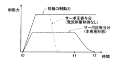
- the limit control for providing the control current may be executed in the section from t1 to t2 in FIG. 3 in the present embodiment. As a result, the same effects as in this example are exhibited in the above embodiment.
- the limited current may be variable according to the voltage of sub power storage unit 92. For example, microcomputer 80 may decrease the limited current as the voltage of sub power storage unit 92 decreases.
- the microcomputer 80 may reduce the value of the target servo pressure with respect to the pedal effort as the voltage of the sub power storage unit 92 decreases.
- the microcomputer 80 stores, for example, a plurality of different specific maps, and switches to a specific map in which the target servo pressure becomes smaller (that is, a heavier operation feeling is produced) according to the decrease in the voltage of the sub power storage unit 92. May be.
- microcomputer 80 may decrease the rotation speed of motor 31, that is, the required power, as the voltage of sub power storage unit 92 decreases. With such a configuration, it is possible to promptly increase the operation driving force more clearly and smoothly.
- the limit control in addition to the stepwise reduction of the power amount or the current amount with respect to the reduction of the remaining power amount as in the present embodiment, the power amount or the current amount is linearly reduced with respect to the reduction of the remaining power amount. It may be reduced.
- the limitation control of the present embodiment can be executed regardless of the presence / absence of sub power storage unit 92 with respect to the reduction of the remaining power amount of power storage unit 9.
- the microcomputer 80 may execute various limit controls when the voltage of the power storage unit 9 is low.
- the map changing control the map indicating the relationship between the stroke and the target servo pressure may be changed for abnormal time so that the target servo pressure for the stroke becomes smaller.
- the vehicle braking device 1 is not limited to the by-wire configuration as in the present embodiment, and may have a configuration in which the master piston is constantly driven by the servo driving force and the operation driving force as in the known configuration, for example. Good.
- the microcomputer 80 can execute the limit control without considering the brake feeling.
- the microcomputer 80 may execute the limitation control regardless of whether or not the brake operation is performed, even if the microcomputer 80 has a by-wire configuration.
- the electric device may be a device other than the motor 31. Further, the microcomputer 80 may independently execute only the map change control.
- the vehicle braking device 1 may not include the solenoid valve 36.
- the hydraulic circuit (64) corresponding to the wheel that generates the regenerative braking force may be connected to the output chamber 212.
Landscapes
- Engineering & Computer Science (AREA)
- Transportation (AREA)
- Mechanical Engineering (AREA)
- Power Engineering (AREA)
- Regulating Braking Force (AREA)
- Valves And Accessory Devices For Braking Systems (AREA)
- Charge And Discharge Circuits For Batteries Or The Like (AREA)
- Transmission Of Braking Force In Braking Systems (AREA)
- Braking Systems And Boosters (AREA)
Abstract
本発明は、蓄電部9から電力の供給を受ける電気機器31の作動により車両の車輪に制動力を付与する車両用制動装置において、電気機器31の作動による第1駆動力とドライバの制動操作による第2駆動力とにより駆動される第1ピストン22と、第1ピストン22が摺動可能に収納されているシリンダ21と、第1ピストン22とシリンダ21とにより区画されてホイールシリンダ51、52に接続される出力室212と、を有する液圧発生装置2と、蓄電部9に残存している残存電力量が少なくなるほど、蓄電部9から電気機器31に供給される電力量又は電流量を制限する制限制御を実行する制御部80と、を備える。
Description
本発明は、車両用制動装置に関する。
車両用制動装置の多くは、ECU(電子制御ユニット)等に電力を供給する電源として、メイン電源と、サブ電源と、を備えている。サブ電源は、多くの場合、メイン電源に比べて容量が小さく、メイン電源から充電されるように構成されている。メイン電源とサブ電源との切り替えは、メイン電源の残存電力量の低下など、諸条件の下で行われる。電源の切り替えに関し、例えば特開2010-120624号公報に記載の装置では、メイン電源の電力の残量が第1の所定値未満に低下すると、サブ電源を制御部(ECU)に接続し、メイン電源の電力の残量が第1の所定値よりも低い値である第2の所定値未満まで低下すると、サブ電源をアクチュエータにも接続する。これにより、サブ電源から制御部への電力供給を相対的に早くし、サブ電源からアクチュエータへの電力供給を相対的に遅くしている。この装置では、サブ電源とアクチュエータとの接続タイミングの適正化が図られている。
アクチュエータのモータなどの電気機器は、駆動するのに比較的大きな電力を必要とする。消費電力の観点において、モータは、ECUよりもはるかに大きい。当然ながら、電源の電力がすべて消費されると、モータの駆動は停止し、電気機器による制動力の発生は止まってしまう。そこで、発明者は、車両用制動装置において、例えば異常発生時でも、限られた電力の中で、電気機器への電力供給時間をできるだけ長くし、より安定的に制動力を確保することを新たな課題とし、開発を行った。
本発明は、このような事情に鑑みて為されたものであり、電源に異常が発生した際でも、長く安定的に制動力を発生させることができる車両用制動装置を提供することを目的とする。
本発明の車両用制動装置は、蓄電部から電力の供給を受ける電気機器の作動により車両の車輪に制動力を付与する車両用制動装置において、前記電気機器の作動による第1駆動力とドライバの制動操作による第2駆動力とにより駆動される第1ピストンと、前記第1ピストンが摺動可能に収納されているシリンダと、前記第1ピストンと前記シリンダとにより区画されてホイールシリンダに接続される出力室と、を有する液圧発生装置と、前記蓄電部に残存している残存電力量が少なくなるほど、前記蓄電部から前記電気機器に供給される電力量又は電流量を制限する制限制御を実行する制御部と、を備える。
本発明によれば、蓄電部が電気機器に供給する電力量又は電流量を制限することで、蓄電部の消費電力を抑え、電気機器への電力供給時間を長くすることができる。また、制限制御の実行に伴い第1駆動力により発生する制動力が低下するが、これによりドライバによる異常の認知が促されるとともに、ドライバのさらなる制動操作が促される。つまり、本発明によれば、蓄電部に異常が発生した時でも、通常時よりも小さいが長く第1駆動力を発生させ、ドライバの操作による第2駆動力の増大を促すことで、長く安定的に制動力を発生させることができる。
以下、本発明の実施形態について図に基づいて説明する。説明に用いる各図は概念図であり、各部の形状は厳密なものではない。本実施形態の車両用制動装置1は、図1に示すように、マスタシリンダ2と、フルード供給部3と、アクチュエータ4と、ホイールシリンダ51、52、53、54と、ブレーキECU8と、蓄電部9と、を備えている。
マスタシリンダ2は、前輪Wfのホイールシリンダ51、52にフルードを供給するように構成された液圧発生装置である。マスタシリンダ2は、入力ピストン(「第2ピストン」に相当する)20と、シリンダ21と、マスタピストン(「第1ピストン」に相当する)22と、リザーバ23と、スプリング24と、を備えている。入力ピストン20は、ピストン部材であって、ブレーキ操作部材であるブレーキペダル11の作動に連動してシリンダ21内を摺動する。車両用制動装置1には、ブレーキペダル11のストロークを検出するストロークセンサ12が設けられている。
シリンダ21は、内部空間がマスタピストン22により、入力室211と出力室212とに区画されたシリンダ部材である。より詳細に、シリンダ21の内部には、入力室211、出力室212、離間室213、及び反力室214が形成されている。入力室211及び出力室212については後述する。
離間室213は、入力ピストン20とマスタピストン22とで区画されている。マスタピストン22と入力ピストン20とは、所定距離だけ離間してすなわち離間室213を介して、対向配置されている。離間室213は、流路71及びノーマルクローズ型の第1電磁弁72を介してストロークシミュレータ73に接続されている。離間室213の液圧であって入力ピストン20の前進に対する反力は、第1電磁弁72が開状態において、ストロークシミュレータ73により形成される。流路71に接続された圧力センサ78は、離間室213の液圧である反力圧、及びブレーキペダル11に対するドライバの踏力を検出する。
反力室214は、マスタピストン22により区画されている。反力室214は、マスタピストン22が前進すると容積が減少し、マスタピストン22が後退すると容積が増大するように形成されている。反力室214は、流路74及びノーマルオープン型の第2電磁弁75を介してリザーバ76に接続されている。流路74のうち第2電磁弁75と反力室214との間の部分は、流路77を介して、流路71の第1電磁弁72とストロークシミュレータ73との間の部分と接続されている。流路74に接続された圧力センサ79は、反力室214の液圧を検出する。
マスタピストン22は、シリンダ21内に配置されたピストン部材である。マスタピストン22は、出力室212の容積を変化させるようにシリンダ21内を摺動し、入力室211内の液圧に対応する力で駆動されて、出力室212に液圧(以下「マスタ圧」という)を発生させる。マスタピストン22は、入力室211と反力室214とを区画するように、他の部位より大径に形成された大径部221を有している。
入力室211は、いわゆるサーボ室であって、マスタピストン22の大径部221の後方側に形成されている。入力室211は、大径部221を介して、反力室214と対向するように形成されている。入力室211の液圧(以下「サーボ圧」という)は、大径部221の後端面を押圧し、マスタピストン22を前進させる力である駆動力となる。入力室211には、後述する接続流路65を介してフルード供給部3が接続されている。
出力室212は、いわゆるマスタ室であって、シリンダ21の底面側すなわちマスタピストン22の前方に形成されている。出力室212は、マスタピストン22が前進すると容積が減少し、マスタピストン22が後退すると容積が増大するように形成されている。出力室212は、第2流路62を介して、アクチュエータ4に接続されている。
このように、マスタシリンダ2は、シリンダ21と、シリンダ21内を摺動可能に配置されたマスタピストン22と、を有し、シリンダ21にはマスタピストン22によって区画された入力室211と出力室212とが形成されている。
リザーバ23は、フルードを貯留しているタンクであり、大気圧に保たれている。リザーバ23と出力室212とをつなぐ流路は、マスタピストン22が初期位置にある場合に連通され、マスタピストン22が初期位置から所定距離前進すると遮断される。スプリング24は、マスタピストン22を初期位置に向けて(すなわち後方に)押圧する。
例えば電源失陥が発生した場合は、各電磁弁72、75が非通電状態となるため、第1電磁弁72は閉弁され、第2電磁弁75は開弁される。これにより、離間室213が密閉されて、入力ピストン20とマスタピストン22との離間距離が固定され、且つ反力室214がリザーバ76に連通される。この離間距離がロックされた状態(以下「離間ロック状態」という)では、入力ピストン20の前進に応じてマスタピストン22も前進する。つまり、離間ロック状態では、ドライバの踏力だけでマスタ圧を発生させることができる。離間ロック状態では、マスタピストン22が、ドライバの制動操作による操作駆動力(「第2駆動力」に相当する)のみにより駆動される。離間ロック状態は、電源失陥時だけでなく、ブレーキECU8の制御によっても形成できる。
このように、車両用制動装置1は、操作駆動力のマスタピストン22への伝達を許可又は遮断する遮断機構70を備えている。遮断機構70は、ドライバの制動操作に連動する入力ピストン20と、入力ピストン20とマスタピストン22との間に離間室213を区画する離間室区画部25と、離間室213を密閉又は開放する第1電磁弁72と、を備えている。本実施形態の離間室区画部25は、入力ピストン20の前端面、マスタピストン22の後端面、及びシリンダ21で構成されるといえる。また、車両用制動装置1は、マスタピストン22の前進により容積が縮小する反力室214に接続されたストロークシミュレータ73と、反力室214とリザーバ76との接続を開閉する第2電磁弁75と、を有する反力発生機構13を備えている。換言すると、車両用制動装置1は、離間室213に第1電磁弁72を介して接続されたストロークシミュレータ73と、第1電磁弁72とストロークシミュレータ73とを接続する流路71に接続され、マスタピストン22の前進により容積が縮小する反力室214と、反力室214とリザーバ76との接続を開閉する第2電磁弁75と、を備えている。反力発生機構13は、離間室213、第1電磁弁72、ストロークシミュレータ73、反力室214、及び第2電磁弁75を備えているといえる。
フルード供給部3は、アクチュエータ4及び接続流路65にフルードを供給する装置である。フルード供給部3は、第1流路61を介して、アクチュエータ4内の第1液圧回路63にフルードを供給する。第1液圧回路63は、ホイールシリンダ53、54に接続されている。接続流路65は、第1流路61と、マスタシリンダ2の入力室211とを接続する流路である。後述する電磁弁36が開状態である場合又は電磁弁36がない場合、フルード供給部3が接続流路65に供給したフルードは、第1液圧回路63と入力室211とに供給される。
フルード供給部3からホイールシリンダ51~54までの液圧の伝達経路は、後輪Wrのホイールシリンダ53、54に接続される第1系統6Aと、前輪Wfのホイールシリンダ51、52に接続される第2系統6Bと、第1系統6Aと第2系統6Bとを接続する接続流路65と、を含んでいる。第1系統6Aは、第1流路61と、第1液圧回路63と、を含んでいる。第2系統6Bは、マスタシリンダ2と、第2流路62と、アクチュエータ4内の第2液圧回路64と、を含んでいる。第2液圧回路64は、ホイールシリンダ51、52に接続されている。このように、車両用制動装置1は、フルード供給部3と、フルード供給部3と第1車輪に相当する後輪Wrとを接続する第1系統6Aと、第2車輪に相当する前輪Wfに接続された第2系統6Bと、第1系統6Aと第2系統6Bとを接続する接続流路65と、を備えている。
フルード供給部3は、モータ(「電気機器」に相当する)31と、ポンプ32と、リザーバ33と、環状流路34と、電磁弁35と、電磁弁36と、を備えている。モータ31は、ブレーキECU8により駆動が制御され、ポンプ32を駆動させる電動モータである。ポンプ32は、例えばギアポンプであって、モータ31の駆動力により駆動する。ポンプ32は、リザーバ33に貯留されたフルードを吸入し、第1流路61及び接続流路65に吐出する。環状流路34は、ポンプ32の吐出口と吸入口とをつなぐ流路であって、流路341、342、343、344で構成されている。
流路341は、ポンプ32の吐出口と第1流路61及び接続流路65とを接続している。流路342は、接続流路65とリザーバ33とを接続している。流路342には、電磁弁35が設けられている。流路343は、接続流路65のうち流路341と流路342とを接続している部分である。つまり、接続流路65は、入力室211と環状流路34とを接続する流路650と、環状流路34の一部である流路343と、で構成されている。流路343すなわち接続流路65の一部の区間には、電磁弁36が設けられている。流路344は、リザーバ33とポンプ32の吸入口とを接続している。
流路341には、流路341及び第1流路61の液圧を検出する圧力センサ37が設けられている。圧力センサ37が検出する液圧は、ポンプ32が第1液圧回路63及び接続流路65に供給する液圧といえる。なお、入力室211の液圧であるサーボ圧は、電磁弁36の制御状態によって変動する。また、本実施形態では、リザーバ33、リザーバ76、及びリザーバ23は、1つの共通リザーバ(例えばリザーバ23)で構成されている。
電磁弁35及び電磁弁36は、ノーマルオープン型の電磁弁であって、上下流間の差圧を制御できるリニア弁である。電磁弁35及び電磁弁36は、ブレーキECU8からの制御電流の大きさに基づいて、上流側の液圧を下流側の液圧より高くする。電磁弁35及び電磁弁36の目標差圧は、制御電流の大きさによって決まる。電磁弁35及び電磁弁36は、制御電流に応じて流路に絞り状態を形成するといえる。
上記のように、フルード供給部3は、モータ31と、モータ31の回転数に応じた吐出量で第1系統6Aにフルードを供給するポンプ32と、を有している。また、接続流路65は、入力室211に接続され、第2系統6Bは、出力室212に接続されている。また、マスタシリンダ2は、モータ31の作動によるサーボ駆動力(「第1駆動力」に相当する)とドライバの制動操作による操作駆動力とにより駆動されるマスタピストン22と、マスタピストン22が摺動可能に収納されているシリンダ21と、マスタピストン22とシリンダ21とにより区画されてホイールシリンダ51、52に接続される出力室212と、を有している。
ブレーキECU8は、ストロークに対して目標ホイール圧を設定すると、電磁弁35の目標差圧を制御し、ポンプ32を駆動する。これにより、電磁弁35の下流側の液圧であるリザーバ33の液圧(ここでは大気圧)に対して、電磁弁35の上流側(ポンプ32側)の液圧を目標差圧分だけ高くすることができる。また、ブレーキECU8は、アクチュエータ4を用いずに各系統6A、6Bで異なる液圧を発生させる場合、電磁弁36の目標差圧を制御し、ポンプ32を駆動する。これにより、電磁弁36の下流側である電磁弁36と電磁弁35の間の流路の液圧、すなわちサーボ圧に対して、電磁弁36の上流側(ポンプ32側)の液圧を目標差圧分だけ高くすることができる。
ブレーキECU8は、前後輪Wf、Wrで同様のホイール圧を発生させる場合、電磁弁35を制御し、電磁弁36を制御しない。電磁弁36は、例えば前輪Wfに発生させる回生制動力を考慮して、前輪Wfのホイールシリンダ51、52の液圧を、後輪Wrのホイールシリンダ53、54の液圧より低く制御する際に用いられる。
アクチュエータ4は、各ホイール圧を加圧可能に構成されたいわゆるESCアクチュエータである。アクチュエータ4は、第1液圧回路63と、第2液圧回路64と、を備えている。各液圧回路63、64には、図示略の電磁弁、ポンプ、及び調圧リザーバ等が設けられている。ブレーキECU8が各液圧回路63、64に配置された電磁弁及びポンプを制御することで、各ホイール圧を加圧、減圧、又は保持することができる。また、アクチュエータ4は、ブレーキECU8の指令に基づき、アンチスキッド制御や横滑り防止制御を実行することができる。第2液圧回路64又は第2流路62には、マスタ圧を検出する圧力センサ641が設けられている。
ブレーキECU8は、CPUやメモリ等で構成されたマイクロコンピュータ(以下「マイコン」という)80を備える電子制御ユニットである。ブレーキECU8は、各種センサからの情報に基づいて、主にフルード供給部3及びアクチュエータ4を制御する装置である。ブレーキECU8は、ブレーキペダル11が操作されると、ストローク及び/又は踏力に応じて、目標減速度及び目標ホイール圧を設定する。また、ブレーキECU8は、通常時は、第1電磁弁72を開弁させ、第2電磁弁75を閉弁させる。これにより、反力室214とリザーバ76との間が遮断され、離間室213及び反力室214とストロークシミュレータ73との間が連通する。離間室213及び反力室214には、ブレーキペダル11の操作に応じた液圧(反力圧)が発生する。
ブレーキECU8は、回生制動力が発生しない場合、目標ホイール圧に応じて、フルード供給部3のポンプ32及び電磁弁35を制御する。この場合、電磁弁36は、制御されず、非通電による開状態が維持される。ブレーキECU8は、ポンプ32を駆動させるとともに、電磁弁35の目標差圧を目標ホイール圧に対応して設定し、電磁弁35に目標差圧に対応する制御電流を印加する。
ポンプ32は、リザーバ33からフルードを吸入し、第1系統6Aにフルードを供給する。ポンプ32から吐出されたフルードは、接続流路65を介して入力室211にも供給される。入力室211及び第1系統6Aには、電磁弁35の目標差圧に応じた液圧が発生する。
上記制御によりサーボ圧が上昇すると、マスタピストン22が前進し、出力室212の縮小によりマスタ圧が上昇する。つまり、出力室212と接続された第2流路62及び第2液圧回路64の液圧も上昇する。ポンプ32と電磁弁35の制御により、サーボ圧に対応する液圧が、両系統6A、6Bを介して、各ホイールシリンダ51~54に発生する。このように、ブレーキECU8は、目標ホイール圧を達成し、目標減速度を達成するようにブレーキ制御を実行する。なお、厳密には、マスタピストン22の摺動抵抗などにより、第2系統6Bの液圧が第1系統6Aの液圧より若干低くなる。また、ハイブリッド車両など、回生制動装置を備える車両においては、前輪Wfの目標減速度(目標制動力)が回生制動力と液圧制動力との和で達成されるように、電磁弁36の目標差圧が制御される。ブレーキECU8は、各ホイール圧を、圧力センサ37、641の検出値とアクチュエータ4の制御状況とに基づいて推定する。
蓄電部9は、充放電可能な電源システムであって、例えばブレーキECU8、フルード供給部3、及びアクチュエータ4等に電力を供給する。車両用制動装置1は、蓄電部9から電力の供給を受ける電気機器の作動により車両の車輪Wf、Wrに制動力を付与する装置といえる。本実施形態の蓄電部9は、メイン蓄電部91と、メイン蓄電部91により充電されるサブ蓄電部92と、を有している。
メイン蓄電部91は、バッテリであって、図2に示すように、ブレーキECU8のマイコン80及びフルード供給部3のモータ31に電力を供給するように構成されている。なお、メイン蓄電部91は、アクチュエータ4にも電力を供給する。
サブ蓄電部92は、キャパシタであって、例えば電気二重層コンデンサで構成されている。サブ蓄電部92は、スイッチ93を介してマイコン80に接続され、スイッチ93、94を介してモータ31に接続されている。つまり、サブ蓄電部92は、スイッチ93がオンされた場合にマイコン80に電力を供給し、両スイッチ93、94がオンされた場合にマイコン80及びモータ31に電力を供給する。例えば、モータ31は、通常時には、メイン蓄電部91から電力の供給を受け、メイン蓄電部91から電力の供給を受けることができない異常時には、サブ蓄電部92から電力の供給を受ける。この異常時は、メイン蓄電部91が失陥した時である。
メイン蓄電部91及びサブ蓄電部92は、マイコン80への給電方法と同様に、各電磁弁35、36、72、75への制御電流の供給源として機能する。つまり、各電磁弁35、36、72、75は、ブレーキECU8の制御に基づき、蓄電部9すなわちメイン蓄電部91及び/又はサブ蓄電部92から電力を受ける。なお、サブ蓄電部92は、メイン蓄電部91により充電されるとともにメイン蓄電部91の状態を取得するように構成されている。このため、仮にメイン蓄電部91が失陥した場合でも、サブ蓄電部92がスイッチ93をオフからオンに切り替えて、マイコン80に電力を供給する。
また、マイコン80は、アクチュエータ4の制御状態、及び圧力センサ641で検出されるマスタ圧と圧力センサ37で検出される上流圧に基づいて、ホイール圧を推定する。例えばアクチュエータ4が作動していない状態であれば、マスタ圧がホイールシリンダ51、52の液圧となり、上流圧がホイールシリンダ53、54の液圧となる。上流圧は、電磁弁36が制御されていない状態では、サーボ圧に相当する。メイン蓄電部91が正常である通常時は、目標サーボ圧の達成が、目標ホイール圧の達成となる。マイコン80は、目標サーボ圧を達成するために、フルード供給部3に電力を供給し、ポンプ32の回転数等を制御する。
(制限制御)
制御部に相当するマイコン80は、蓄電部9に残存している残存電力量が少なくなるほど、蓄電部9からモータ31に供給される電力量又は電流量を制限する制限制御を実行するように構成されている。マイコン80は、残存電力量が所定量より小さくなると、モータ31への供給電力量を通常時よりも低減させ、ポンプ32の吐出量を低減させる。
制御部に相当するマイコン80は、蓄電部9に残存している残存電力量が少なくなるほど、蓄電部9からモータ31に供給される電力量又は電流量を制限する制限制御を実行するように構成されている。マイコン80は、残存電力量が所定量より小さくなると、モータ31への供給電力量を通常時よりも低減させ、ポンプ32の吐出量を低減させる。
まず、メイン蓄電部91の電圧が第1所定値より小さくなると、スイッチ93がオンされ、マイコン80の電力源が、メイン蓄電部91からサブ蓄電部92に切り替わる。その後、さらにメイン蓄電部91の電圧が第1所定値より小さい第2所定値未満になった場合、マイコン80によりスイッチ94がオンされ、フルード供給部3のモータ31の電力源が、メイン蓄電部91からサブ蓄電部92に切り替わる。つまり、メイン蓄電部91の電圧が第2所定値未満になると、サブ蓄電部92とモータ31及びマイコン80とが接続される。
ここで、本実施形態のマイコン80は、メイン蓄電部91の異常時に、サブ蓄電部92に残存している電力量を残存電力量として制限制御を実行する。マイコン80は、メイン蓄電部91とサブ蓄電部92との供給可能な電力量の合計を残存電力量として把握しているといえる。マイコン80は、モータ31とサブ蓄電部92とを接続する際に、制限制御を実行する。
より詳細に、マイコン80は、制限制御として、電力マネジメント制御を実行する。電力マネジメント制御は、蓄電部9の残存電力量が所定量未満である場合に、遮断機構70により操作駆動力のマスタピストン22への伝達を許可させ、上記アシスト電力未満の制限電力をモータ31に供給する制御である。なお、マイコン80は、通常時は、アシスト制御を実行する。つまり、アシスト制御は、蓄電部9の残存電力量が所定量以上である場合に、遮断機構70により操作駆動力のマスタピストン22への伝達を遮断させ、サーボ駆動力を操作駆動力以上にするアシスト電力をモータ31に供給する制御である。換言すると、アシスト制御は、第1電磁弁72を開弁させ且つ第2電磁弁75を閉弁させた状態で、ストローク及び/又は踏力に応じたサーボ圧を発生させる制御である。アシスト制御は、バイワイヤ状態での制御といえる。
マイコン80は、メイン蓄電部91の電圧が第2所定値未満となった場合、蓄電部9の残存電力量が所定量未満になったと判定し、実行する制御をアシスト制御から電力マネジメント制御に切り替える。マイコン80は、サブ蓄電部92とモータ31とを接続させるとともに、第1電磁弁72を閉弁させ且つ第2電磁弁75を開弁させて、離間室213に対して離間ロック状態を形成する。つまり、マイコン80は、各電磁弁72、75への電力供給を停止することで、操作駆動力のマスタピストン22への伝達を許可させる。これにより、ドライバがブレーキペダル11を踏み込んだ際、操作駆動力がマスタピストン22に伝達され、ドライバの踏力によりマスタ圧及びホイール圧が上昇し、制動力が発生する。
マイコン80は、離間ロック状態の形成と同時に、電力マネジメント制御の一環として、マップ変更制御を実行する。マップ変更制御は、制動制御時に用いるドライバの踏力と目標サーボ圧との関係が設定されたマップについて、通常時用の通常マップを異常時用の特定マップに変更する制御である。特定マップは、ドライバの踏力に対する目標サーボ圧の値が、通常マップよりも小さくなるように設定されている。つまり、特定マップの制御下で、通常マップとで同じサーボ圧を発生させるためには、ドライバは通常マップ時よりも大きな踏力でブレーキペダル11を操作する必要がある。
例えばドライバの踏力が一定である場合、特定マップ制御下で発生するサーボ圧は、通常マップ制御下で発生するサーボ圧よりも低くなる。つまり、ドライバからの同じ要求度(踏力)に対して、特定マップ制御下では、モータ31のトルクすなわち必要電力は相対的に小さくなる。これにより、サブ蓄電部92からポンプ32に供給される電力量(及び電流量)は、通常時よりも小さくなる。換言すると、マップ変更制御により、ポンプ32への供給電力は、アシスト電力から制限電力に変更される。ドライバは、制動力が通常よりも出ないと感じ、ブレーキの異常であることを知るとともに、所望の制動力に向けてさらにブレーキペダル11を踏み込むこととなる。ドライバは、通常よりも重い操作感で所望の制動力を発揮させることとなる。
図3に示すように、サブ蓄電部92とモータ31とが接続され、制限制御が実行された後、ドライバの制動操作が開始されると(t0)、制動力の一部をサーボ駆動力が発生させ、残りの部分を操作駆動力が発生させる。つまり、前輪Wfに発生する制動力は、サーボ駆動力により生じる制動力(サーボ圧寄与分)と、操作駆動力により生じる制動力との和となる。制限制御によれば、通常時よりも踏力に対する目標サーボ圧が低く設定されてモータ31への供給電力が小さくなるが、操作駆動力がマスタピストン22に加わる分、マスタ圧及びホイールシリンダ51、52の液圧が上昇する。換言すると、踏力に対して生じるサーボ圧が低くなる分が、促されたドライバの制動操作によるマスタ圧の上昇によって補われる。
その後、t1以降は、サブ蓄電部92の残存電力量の低下に伴って、モータ31への供給電力は徐々に低下していき、サーボ駆動力は低下していく。この際の制動力の発生要因の割合は、操作駆動力が徐々に大きくなり、サーボ駆動力が徐々に小さくなる。t2においてサーボ駆動力はゼロになるが、そこに至る過程で、ドライバは急激な状態変化なくシームレスに必要な踏力を加えることができる。
本実施形態によれば、制限制御によりサブ蓄電部92の消費電力を抑制することで、サブ蓄電部92のモータ31への給電時間(t0~t2)を長くすることができる。また、サーボ駆動力に操作駆動力が加わるため、マスタピストン22の駆動が助勢されてマスタ圧及びホイール圧が上昇し、所望の制動力を発生させることができる。本実施形態では、電源異常発生時、モータ31への制限電力の供給と離間ロック状態の形成とにより、ドライバによる異常の認知が促され、相対的に長く小さく継続された助勢の下、より安定的に車両を停止させることができる。
このように、少なくともマスタシリンダ2、マイコン80、及び蓄電部9を備える本実施形態の車両用制動装置1によれば、サブ蓄電部92の容量を増大させることなく、蓄電部9に異常が発生した時でも、長く安定的に制動力を発生させることができる。また、離間ロック状態では、各電磁弁72、75への電力供給が不要となるため、その分サブ蓄電部92の消費電力を小さくすることができる。なお、本実施形態の電力マネジメント制御やマップ変更制御については、ドライバのブレーキフィーリング維持の観点において、ドライバによる制動操作が為されていないことを制動の実行条件とすることが好ましい。
(他の制御例)
マイコン80は、サブ蓄電部92とモータ31とが接続された際、サブ蓄電部92の出力電流が予め設定された制限電流以下となるように出力電流を制御する制限制御を実行する。つまり、マイコン80は、蓄電部9の電圧低下に応じて、蓄電部9からモータ31に供給される電流量を制限する。
マイコン80は、サブ蓄電部92とモータ31とが接続された際、サブ蓄電部92の出力電流が予め設定された制限電流以下となるように出力電流を制御する制限制御を実行する。つまり、マイコン80は、蓄電部9の電圧低下に応じて、蓄電部9からモータ31に供給される電流量を制限する。
サブ蓄電部92の電圧が低下し、低下前と同じ供給電力を維持しようとすると、サブ蓄電部92の出力電流が大きくなる。しかし、本例の制限制御によれば、出力電流が制限電流に達すると、マイコン80は、それ以上サブ蓄電部92の出力電流を増大させないように、出力電流を制限する。マイコン80は、サブ蓄電部92の電圧低下に伴い、モータ31の回転数を、出力電流が制限電流を超えない値に設定する。これにより、踏力に対して発生するサーボ圧が相対的に小さくなり、結果としてマップ変更制御を実行した場合と同様の現象が生じる。つまり、サブ蓄電部92の出力電流が制限されると、ドライバは、制動力が通常よりも出ないと感じ、異常を認知するとともに、所望の制動力に向けてさらに制動操作を行う。
マイコン80が出力電流を制限することで、相対的に長い時間サーボ駆動力を発生させることができ、ドライバの制動操作が促されることも加わって、安定的に制動力を発生させることができる。また、電流量が制限されることで、サブ蓄電部92を構成する素子やパターンを、最小限の耐久で設計することができ、コスト増大を抑制することができる。さらに、モータ31とサブ蓄電部92とを接続する配線を細くすることができ、装置の大型化を抑制することができる。なお、本実施形態における図3のt1~t2の区間で、この制御電流を設ける制限制御を実行してもよい。これにより、上記実施形態でも本例同様の効果が発揮される。また、制限電流は、サブ蓄電部92の電圧に応じて可変であってもよい。例えば、マイコン80は、サブ蓄電部92の電圧が低いほど、制限電流を小さくしてもよい。
(その他)
本発明は、上記実施形態に限られない。例えば、マイコン80は、サブ蓄電部92の電圧が低くなるほど、踏力に対する目標サーボ圧の値を小さくしてもよい。この場合、マイコン80は、例えば、複数の異なる特定マップを記憶し、サブ蓄電部92の電圧の低下に応じて、より目標サーボ圧が小さくなる(すなわちより重い操作感が出る)特定マップに切り替えてもよい。あるいは、マイコン80は、サブ蓄電部92の電圧が低くなるほど、モータ31の回転数すなわち必要電力を小さくしてもよい。これらのような構成により、より明確且つスムーズに操作駆動力の増大を促すことができる。
本発明は、上記実施形態に限られない。例えば、マイコン80は、サブ蓄電部92の電圧が低くなるほど、踏力に対する目標サーボ圧の値を小さくしてもよい。この場合、マイコン80は、例えば、複数の異なる特定マップを記憶し、サブ蓄電部92の電圧の低下に応じて、より目標サーボ圧が小さくなる(すなわちより重い操作感が出る)特定マップに切り替えてもよい。あるいは、マイコン80は、サブ蓄電部92の電圧が低くなるほど、モータ31の回転数すなわち必要電力を小さくしてもよい。これらのような構成により、より明確且つスムーズに操作駆動力の増大を促すことができる。
また、制限制御において、本実施形態のように残存電力量の減少に対して段階的に電力量又は電流量を低減させる以外に、残存電力量の減少に対してリニアに電力量又は電流量を低減させてもよい。また、本実施形態の制限制御は、サブ蓄電部92の有無にかかわらず、蓄電部9の残存電力量の減少に対して実行することができる。マイコン80は、蓄電部9の低電圧時に、各種の制限制御を実行してもよい。また、マップ変更制御では、ストロークに対する目標サーボ圧が小さくなるように、ストロークと目標サーボ圧との関係を示すマップを異常時用に変更してもよい。
また、車両用制動装置1は、本実施形態のようなバイワイヤ構成に限らず、例えば公知の構成のように、常時、サーボ駆動力と操作駆動力とによりマスタピストンを駆動させる構成であってもよい。このように、常時、サーボ駆動力と操作駆動力とが同時にマスタピストンに加わる構成では、制限制御の実行タイミングが制動操作中であっても、制限制御によるブレーキフィーリングへの影響は小さい。つまり、この構成において、マイコン80は、ブレーキフィーリングを考慮することなく、制限制御を実行することができる。なお、マイコン80は、バイワイヤ構成であっても、ブレーキ操作の有無にかかわらず、制限制御を実行してもよい。また、電気機器は、モータ31以外の装置でもよい。また、マイコン80は、マップ変更制御のみを独立して実行してもよい。
また、例えば2つの系統6A、6Bに対して上流側で異なる液圧を供給する必要がない場合、車両用制動装置1は、電磁弁36を備えなくてもよい。前後輪Wf、Wrの一方に回生制動力を発生させる車両では、回生制動力を発生させる車輪に対応する液圧回路(64)が出力室212に接続されるように構成されればよい。
Claims (5)
- 蓄電部から電力の供給を受ける電気機器の作動により車両の車輪に制動力を付与する車両用制動装置において、
前記電気機器の作動による第1駆動力とドライバの制動操作による第2駆動力とにより駆動される第1ピストンと、前記第1ピストンが摺動可能に収納されているシリンダと、前記第1ピストンと前記シリンダとにより区画されてホイールシリンダに接続される出力室と、を有する液圧発生装置と、
前記蓄電部に残存している残存電力量が少なくなるほど、前記蓄電部から前記電気機器に供給される電力量又は電流量を制限する制限制御を実行する制御部と、
を備える車両用制動装置。 - 前記蓄電部は、メイン蓄電部と、前記メイン蓄電部により充電されるサブ蓄電部と、を有し、
前記電気機器は、通常時には、前記メイン蓄電部から電力の供給を受け、前記メイン蓄電部から電力の供給を受けることができない異常時には、前記サブ蓄電部から電力の供給を受け、
前記制御部は、前記異常時に、前記サブ蓄電部に残存している電力量を前記残存電力量として前記制限制御を実行する、請求項1に記載の車両用制動装置。 - 前記第2駆動力の前記第1ピストンへの伝達を許可又は遮断する遮断機構を備え、
前記制御部は、
前記残存電力量が所定量以上である場合に、前記遮断機構により前記第2駆動力の前記第1ピストンへの伝達を遮断させ、前記第1駆動力を前記第2駆動力以上にするアシスト電力を前記電気機器に供給するアシスト制御を実行し、
前記残存電力量が所定量未満である場合に、前記制限制御として、前記遮断機構により前記第2駆動力の前記第1ピストンへの伝達を許可させ、前記アシスト電力未満の制限電力を前記電気機器に供給する電力マネジメント制御を実行する、請求項1又は2に記載の車両用制動装置。 - 前記遮断機構は、前記制動操作に連動する第2ピストンと、前記第2ピストンと前記第1ピストンとの間に離間室を区画する離間室区画部と、前記離間室を密閉又は開放する第1電磁弁と、を有し、
前記第1電磁弁は、前記蓄電部から電力の供給を受けるノーマルクローズ型の電磁弁である、請求項3に記載の車両用制動装置。 - 前記第1ピストンの前進により容積が縮小する反力室に接続されたストロークシミュレータと、前記反力室とリザーバとの接続を開閉する第2電磁弁と、を有する反力発生機構を更に備え、
前記第2電磁弁は、前記蓄電部から電力の供給を受けるノーマルオープン型の電磁弁である請求項1~4の何れか一項に記載の車両用制動装置。
Applications Claiming Priority (2)
| Application Number | Priority Date | Filing Date | Title |
|---|---|---|---|
| JP2018-215858 | 2018-11-16 | ||
| JP2018215858A JP7192425B2 (ja) | 2018-11-16 | 2018-11-16 | 車両用制動装置 |
Publications (1)
| Publication Number | Publication Date |
|---|---|
| WO2020101010A1 true WO2020101010A1 (ja) | 2020-05-22 |
Family
ID=70731850
Family Applications (1)
| Application Number | Title | Priority Date | Filing Date |
|---|---|---|---|
| PCT/JP2019/044810 Ceased WO2020101010A1 (ja) | 2018-11-16 | 2019-11-15 | 車両用制動装置 |
Country Status (2)
| Country | Link |
|---|---|
| JP (1) | JP7192425B2 (ja) |
| WO (1) | WO2020101010A1 (ja) |
Cited By (1)
| Publication number | Priority date | Publication date | Assignee | Title |
|---|---|---|---|---|
| DE102022205459A1 (de) | 2022-05-31 | 2023-11-30 | Continental Automotive Technologies GmbH | Energiesparender Betriebsmodus |
Families Citing this family (1)
| Publication number | Priority date | Publication date | Assignee | Title |
|---|---|---|---|---|
| JP7359795B2 (ja) * | 2021-03-04 | 2023-10-11 | トヨタ自動車株式会社 | 車両用ブレーキシステム |
Citations (5)
| Publication number | Priority date | Publication date | Assignee | Title |
|---|---|---|---|---|
| JPH1053122A (ja) * | 1996-08-08 | 1998-02-24 | Unisia Jecs Corp | 電動式ブレーキ倍力装置 |
| JP2007160992A (ja) * | 2005-12-12 | 2007-06-28 | Isao Matsuno | 車両用ブレーキ装置 |
| JP2010120522A (ja) * | 2008-11-20 | 2010-06-03 | Nissan Motor Co Ltd | 車両用制動装置および車両用制動装置の制御方法 |
| WO2010113574A1 (ja) * | 2009-03-31 | 2010-10-07 | 日立オートモティブシステムズ株式会社 | ブレーキ制御装置 |
| JP2013199142A (ja) * | 2012-03-23 | 2013-10-03 | Advics Co Ltd | 車両用液圧ブレーキ装置 |
-
2018
- 2018-11-16 JP JP2018215858A patent/JP7192425B2/ja active Active
-
2019
- 2019-11-15 WO PCT/JP2019/044810 patent/WO2020101010A1/ja not_active Ceased
Patent Citations (5)
| Publication number | Priority date | Publication date | Assignee | Title |
|---|---|---|---|---|
| JPH1053122A (ja) * | 1996-08-08 | 1998-02-24 | Unisia Jecs Corp | 電動式ブレーキ倍力装置 |
| JP2007160992A (ja) * | 2005-12-12 | 2007-06-28 | Isao Matsuno | 車両用ブレーキ装置 |
| JP2010120522A (ja) * | 2008-11-20 | 2010-06-03 | Nissan Motor Co Ltd | 車両用制動装置および車両用制動装置の制御方法 |
| WO2010113574A1 (ja) * | 2009-03-31 | 2010-10-07 | 日立オートモティブシステムズ株式会社 | ブレーキ制御装置 |
| JP2013199142A (ja) * | 2012-03-23 | 2013-10-03 | Advics Co Ltd | 車両用液圧ブレーキ装置 |
Cited By (1)
| Publication number | Priority date | Publication date | Assignee | Title |
|---|---|---|---|---|
| DE102022205459A1 (de) | 2022-05-31 | 2023-11-30 | Continental Automotive Technologies GmbH | Energiesparender Betriebsmodus |
Also Published As
| Publication number | Publication date |
|---|---|
| JP2020082813A (ja) | 2020-06-04 |
| JP7192425B2 (ja) | 2022-12-20 |
Similar Documents
| Publication | Publication Date | Title |
|---|---|---|
| CN111372829B (zh) | 电动助力装置以及制动控制装置 | |
| US8801112B2 (en) | Brake device | |
| CN111683845B (zh) | 车辆的制动控制装置 | |
| US20190092304A1 (en) | Vehicle brake system with auxiliary pressure source | |
| JP4760246B2 (ja) | 液圧ブレーキ装置 | |
| US9573578B2 (en) | Electric brake device | |
| WO2012073353A1 (ja) | 液圧ブレーキシステム | |
| US9387765B2 (en) | Vehicle braking control device | |
| WO2017006631A1 (ja) | ブレーキ制御装置およびブレーキシステム | |
| JP2009286170A (ja) | 車両用ブレーキ制御装置 | |
| WO2017146194A1 (ja) | 車両用制動装置 | |
| JP2015071382A (ja) | 車両用制動力発生装置 | |
| WO2018096978A1 (ja) | ブレーキ装置、及びブレーキ装置の制御方法 | |
| JP7359795B2 (ja) | 車両用ブレーキシステム | |
| JP7192425B2 (ja) | 車両用制動装置 | |
| US9889830B2 (en) | Vehicle braking system | |
| WO2017150360A1 (ja) | ブレーキ装置およびブレーキ制御方法 | |
| JP6299035B2 (ja) | ブレーキ装置の駆動回路 | |
| KR102620657B1 (ko) | 차량의 제동장치 및 그 제어방법 | |
| WO2020235531A1 (ja) | 制動制御装置 | |
| KR20230085887A (ko) | 접액식 볼 스크루를 구비하는 압력 평형 psu 피스톤 및 백업 펌프 조립체를 포함하는 브레이크 바이 와이어 모듈 | |
| JP7167656B2 (ja) | 車両用制動装置 | |
| JP2013010505A (ja) | ブレーキ装置 | |
| US11524669B2 (en) | Brake controller | |
| WO2021187435A1 (ja) | 車両用制動装置 |
Legal Events
| Date | Code | Title | Description |
|---|---|---|---|
| 121 | Ep: the epo has been informed by wipo that ep was designated in this application |
Ref document number: 19885999 Country of ref document: EP Kind code of ref document: A1 |
|
| NENP | Non-entry into the national phase |
Ref country code: DE |
|
| 122 | Ep: pct application non-entry in european phase |
Ref document number: 19885999 Country of ref document: EP Kind code of ref document: A1 |