WO2020101005A1 - ショベル、ショベルの制御装置 - Google Patents
ショベル、ショベルの制御装置 Download PDFInfo
- Publication number
- WO2020101005A1 WO2020101005A1 PCT/JP2019/044785 JP2019044785W WO2020101005A1 WO 2020101005 A1 WO2020101005 A1 WO 2020101005A1 JP 2019044785 W JP2019044785 W JP 2019044785W WO 2020101005 A1 WO2020101005 A1 WO 2020101005A1
- Authority
- WO
- WIPO (PCT)
- Prior art keywords
- shovel
- control
- construction surface
- target construction
- controller
- Prior art date
Links
- 238000010276 construction Methods 0.000 claims abstract description 245
- 238000013459 approach Methods 0.000 claims abstract description 12
- 230000008859 change Effects 0.000 claims description 19
- 238000005516 engineering process Methods 0.000 abstract 1
- 230000006870 function Effects 0.000 description 89
- 239000010720 hydraulic oil Substances 0.000 description 75
- 210000003371 toe Anatomy 0.000 description 72
- 230000033001 locomotion Effects 0.000 description 57
- 238000001514 detection method Methods 0.000 description 51
- 238000000034 method Methods 0.000 description 50
- 238000006073 displacement reaction Methods 0.000 description 48
- 230000008569 process Effects 0.000 description 47
- 238000003384 imaging method Methods 0.000 description 27
- 239000003921 oil Substances 0.000 description 27
- 238000012544 monitoring process Methods 0.000 description 21
- 239000013642 negative control Substances 0.000 description 18
- 230000005856 abnormality Effects 0.000 description 16
- 238000004891 communication Methods 0.000 description 15
- 238000010586 diagram Methods 0.000 description 15
- 238000012545 processing Methods 0.000 description 10
- 230000005540 biological transmission Effects 0.000 description 5
- 230000004044 response Effects 0.000 description 5
- 238000009412 basement excavation Methods 0.000 description 4
- 230000007423 decrease Effects 0.000 description 4
- 230000007935 neutral effect Effects 0.000 description 4
- 238000011144 upstream manufacturing Methods 0.000 description 4
- 230000007246 mechanism Effects 0.000 description 3
- 238000010295 mobile communication Methods 0.000 description 3
- 101001139126 Homo sapiens Krueppel-like factor 6 Proteins 0.000 description 2
- 230000001133 acceleration Effects 0.000 description 2
- 239000012530 fluid Substances 0.000 description 2
- 230000004048 modification Effects 0.000 description 2
- 238000012986 modification Methods 0.000 description 2
- 230000002093 peripheral effect Effects 0.000 description 2
- 238000003825 pressing Methods 0.000 description 2
- 239000002689 soil Substances 0.000 description 2
- 230000000007 visual effect Effects 0.000 description 2
- 101000911772 Homo sapiens Hsc70-interacting protein Proteins 0.000 description 1
- 239000000470 constituent Substances 0.000 description 1
- 238000007599 discharging Methods 0.000 description 1
- 239000000446 fuel Substances 0.000 description 1
- 230000005484 gravity Effects 0.000 description 1
- 230000007774 longterm Effects 0.000 description 1
- 239000000463 material Substances 0.000 description 1
- 238000005259 measurement Methods 0.000 description 1
- 238000005086 pumping Methods 0.000 description 1
- 239000004576 sand Substances 0.000 description 1
- 239000004065 semiconductor Substances 0.000 description 1
- 238000007493 shaping process Methods 0.000 description 1
- 238000009987 spinning Methods 0.000 description 1
- 230000009466 transformation Effects 0.000 description 1
- 230000007704 transition Effects 0.000 description 1
Images


Classifications
-
- E—FIXED CONSTRUCTIONS
- E02—HYDRAULIC ENGINEERING; FOUNDATIONS; SOIL SHIFTING
- E02F—DREDGING; SOIL-SHIFTING
- E02F9/00—Component parts of dredgers or soil-shifting machines, not restricted to one of the kinds covered by groups E02F3/00 - E02F7/00
- E02F9/20—Drives; Control devices
- E02F9/22—Hydraulic or pneumatic drives
- E02F9/2278—Hydraulic circuits
- E02F9/2296—Systems with a variable displacement pump
-
- E—FIXED CONSTRUCTIONS
- E02—HYDRAULIC ENGINEERING; FOUNDATIONS; SOIL SHIFTING
- E02F—DREDGING; SOIL-SHIFTING
- E02F9/00—Component parts of dredgers or soil-shifting machines, not restricted to one of the kinds covered by groups E02F3/00 - E02F7/00
- E02F9/20—Drives; Control devices
-
- E—FIXED CONSTRUCTIONS
- E02—HYDRAULIC ENGINEERING; FOUNDATIONS; SOIL SHIFTING
- E02F—DREDGING; SOIL-SHIFTING
- E02F9/00—Component parts of dredgers or soil-shifting machines, not restricted to one of the kinds covered by groups E02F3/00 - E02F7/00
- E02F9/20—Drives; Control devices
- E02F9/2025—Particular purposes of control systems not otherwise provided for
- E02F9/2033—Limiting the movement of frames or implements, e.g. to avoid collision between implements and the cabin
-
- E—FIXED CONSTRUCTIONS
- E02—HYDRAULIC ENGINEERING; FOUNDATIONS; SOIL SHIFTING
- E02F—DREDGING; SOIL-SHIFTING
- E02F3/00—Dredgers; Soil-shifting machines
- E02F3/04—Dredgers; Soil-shifting machines mechanically-driven
- E02F3/28—Dredgers; Soil-shifting machines mechanically-driven with digging tools mounted on a dipper- or bucket-arm, i.e. there is either one arm or a pair of arms, e.g. dippers, buckets
- E02F3/30—Dredgers; Soil-shifting machines mechanically-driven with digging tools mounted on a dipper- or bucket-arm, i.e. there is either one arm or a pair of arms, e.g. dippers, buckets with a dipper-arm pivoted on a cantilever beam, i.e. boom
- E02F3/32—Dredgers; Soil-shifting machines mechanically-driven with digging tools mounted on a dipper- or bucket-arm, i.e. there is either one arm or a pair of arms, e.g. dippers, buckets with a dipper-arm pivoted on a cantilever beam, i.e. boom working downwardly and towards the machine, e.g. with backhoes
-
- E—FIXED CONSTRUCTIONS
- E02—HYDRAULIC ENGINEERING; FOUNDATIONS; SOIL SHIFTING
- E02F—DREDGING; SOIL-SHIFTING
- E02F3/00—Dredgers; Soil-shifting machines
- E02F3/04—Dredgers; Soil-shifting machines mechanically-driven
- E02F3/28—Dredgers; Soil-shifting machines mechanically-driven with digging tools mounted on a dipper- or bucket-arm, i.e. there is either one arm or a pair of arms, e.g. dippers, buckets
- E02F3/36—Component parts
- E02F3/42—Drives for dippers, buckets, dipper-arms or bucket-arms
- E02F3/43—Control of dipper or bucket position; Control of sequence of drive operations
- E02F3/435—Control of dipper or bucket position; Control of sequence of drive operations for dipper-arms, backhoes or the like
-
- E—FIXED CONSTRUCTIONS
- E02—HYDRAULIC ENGINEERING; FOUNDATIONS; SOIL SHIFTING
- E02F—DREDGING; SOIL-SHIFTING
- E02F9/00—Component parts of dredgers or soil-shifting machines, not restricted to one of the kinds covered by groups E02F3/00 - E02F7/00
- E02F9/02—Travelling-gear, e.g. associated with slewing gears
-
- E—FIXED CONSTRUCTIONS
- E02—HYDRAULIC ENGINEERING; FOUNDATIONS; SOIL SHIFTING
- E02F—DREDGING; SOIL-SHIFTING
- E02F9/00—Component parts of dredgers or soil-shifting machines, not restricted to one of the kinds covered by groups E02F3/00 - E02F7/00
- E02F9/08—Superstructures; Supports for superstructures
- E02F9/10—Supports for movable superstructures mounted on travelling or walking gears or on other superstructures
- E02F9/12—Slewing or traversing gears
- E02F9/121—Turntables, i.e. structure rotatable about 360°
- E02F9/123—Drives or control devices specially adapted therefor
-
- E—FIXED CONSTRUCTIONS
- E02—HYDRAULIC ENGINEERING; FOUNDATIONS; SOIL SHIFTING
- E02F—DREDGING; SOIL-SHIFTING
- E02F9/00—Component parts of dredgers or soil-shifting machines, not restricted to one of the kinds covered by groups E02F3/00 - E02F7/00
- E02F9/20—Drives; Control devices
- E02F9/2004—Control mechanisms, e.g. control levers
-
- E—FIXED CONSTRUCTIONS
- E02—HYDRAULIC ENGINEERING; FOUNDATIONS; SOIL SHIFTING
- E02F—DREDGING; SOIL-SHIFTING
- E02F9/00—Component parts of dredgers or soil-shifting machines, not restricted to one of the kinds covered by groups E02F3/00 - E02F7/00
- E02F9/20—Drives; Control devices
- E02F9/2025—Particular purposes of control systems not otherwise provided for
- E02F9/205—Remotely operated machines, e.g. unmanned vehicles
-
- E—FIXED CONSTRUCTIONS
- E02—HYDRAULIC ENGINEERING; FOUNDATIONS; SOIL SHIFTING
- E02F—DREDGING; SOIL-SHIFTING
- E02F9/00—Component parts of dredgers or soil-shifting machines, not restricted to one of the kinds covered by groups E02F3/00 - E02F7/00
- E02F9/20—Drives; Control devices
- E02F9/22—Hydraulic or pneumatic drives
- E02F9/2278—Hydraulic circuits
- E02F9/2282—Systems using center bypass type changeover valves
-
- E—FIXED CONSTRUCTIONS
- E02—HYDRAULIC ENGINEERING; FOUNDATIONS; SOIL SHIFTING
- E02F—DREDGING; SOIL-SHIFTING
- E02F9/00—Component parts of dredgers or soil-shifting machines, not restricted to one of the kinds covered by groups E02F3/00 - E02F7/00
- E02F9/20—Drives; Control devices
- E02F9/22—Hydraulic or pneumatic drives
- E02F9/2278—Hydraulic circuits
- E02F9/2285—Pilot-operated systems
-
- E—FIXED CONSTRUCTIONS
- E02—HYDRAULIC ENGINEERING; FOUNDATIONS; SOIL SHIFTING
- E02F—DREDGING; SOIL-SHIFTING
- E02F9/00—Component parts of dredgers or soil-shifting machines, not restricted to one of the kinds covered by groups E02F3/00 - E02F7/00
- E02F9/20—Drives; Control devices
- E02F9/22—Hydraulic or pneumatic drives
- E02F9/2278—Hydraulic circuits
- E02F9/2292—Systems with two or more pumps
-
- E—FIXED CONSTRUCTIONS
- E02—HYDRAULIC ENGINEERING; FOUNDATIONS; SOIL SHIFTING
- E02F—DREDGING; SOIL-SHIFTING
- E02F9/00—Component parts of dredgers or soil-shifting machines, not restricted to one of the kinds covered by groups E02F3/00 - E02F7/00
- E02F9/24—Safety devices, e.g. for preventing overload
-
- E—FIXED CONSTRUCTIONS
- E02—HYDRAULIC ENGINEERING; FOUNDATIONS; SOIL SHIFTING
- E02F—DREDGING; SOIL-SHIFTING
- E02F9/00—Component parts of dredgers or soil-shifting machines, not restricted to one of the kinds covered by groups E02F3/00 - E02F7/00
- E02F9/26—Indicating devices
-
- E—FIXED CONSTRUCTIONS
- E02—HYDRAULIC ENGINEERING; FOUNDATIONS; SOIL SHIFTING
- E02F—DREDGING; SOIL-SHIFTING
- E02F9/00—Component parts of dredgers or soil-shifting machines, not restricted to one of the kinds covered by groups E02F3/00 - E02F7/00
- E02F9/26—Indicating devices
- E02F9/261—Surveying the work-site to be treated
- E02F9/262—Surveying the work-site to be treated with follow-up actions to control the work tool, e.g. controller
-
- E—FIXED CONSTRUCTIONS
- E02—HYDRAULIC ENGINEERING; FOUNDATIONS; SOIL SHIFTING
- E02F—DREDGING; SOIL-SHIFTING
- E02F9/00—Component parts of dredgers or soil-shifting machines, not restricted to one of the kinds covered by groups E02F3/00 - E02F7/00
- E02F9/26—Indicating devices
- E02F9/267—Diagnosing or detecting failure of vehicles
- E02F9/268—Diagnosing or detecting failure of vehicles with failure correction follow-up actions
-
- E—FIXED CONSTRUCTIONS
- E02—HYDRAULIC ENGINEERING; FOUNDATIONS; SOIL SHIFTING
- E02F—DREDGING; SOIL-SHIFTING
- E02F9/00—Component parts of dredgers or soil-shifting machines, not restricted to one of the kinds covered by groups E02F3/00 - E02F7/00
- E02F9/20—Drives; Control devices
- E02F9/22—Hydraulic or pneumatic drives
- E02F9/2221—Control of flow rate; Load sensing arrangements
Definitions
- the present disclosure relates to excavators and the like.
- Patent Document 1 For example, a technique is known that allows an operator or the like to recognize whether or not the upper revolving structure of the shovel is directly facing a target construction surface such as a slope (see Patent Document 1).
- the operator needs to perform a turning operation or the like in order to make the shovel face the target construction surface. Therefore, the operator may find it annoying each time the operation process is performed to directly face the shovel to the target construction surface.
- An undercarriage An upper revolving structure mounted on the lower traveling structure so as to be revolvable, An actuator capable of changing the direction of the upper swing body, A control device capable of executing a confrontation control for operating the actuator so as to confront the upper revolving structure with the target construction surface, based on information about the target construction surface and information about the orientation of the upper revolving structure.
- the control device performs the facing control so that the upper swing body maintains a state of facing the target construction surface, Excavators are provided.
- An undercarriage An upper revolving structure mounted on the lower traveling structure so as to be revolvable, An attachment attached to the upper swing body, An actuator capable of changing the direction of the upper swing body, A control device capable of executing a confrontation control for operating the actuator so as to confront the upper revolving structure with the target construction surface, based on information about the target construction surface and information about the orientation of the upper revolving structure.
- the control device starts the facing control when the upper revolving superstructure is turned in a direction in which the attachment approaches the target construction surface, Excavators are provided.
- a shovel control device comprising: a lower traveling body; an upper revolving body that is rotatably mounted on the lower traveling body; and an actuator that can change the direction of the upper revolving body. Based on the information about the target construction surface and the information about the orientation of the upper revolving structure, it is configured to be able to execute a confrontation control that operates the actuator so that the upper revolving structure faces the target construction surface. In order to maintain a state in which the revolving structure directly faces the target construction surface, the facing control is performed, A shovel controller is provided.
- An excavator including a lower traveling body, an upper revolving body rotatably mounted on the lower traveling body, an attachment attached to the upper revolving body, and an actuator capable of changing the direction of the upper revolving body.
- Control device of Based on the information on the target construction surface and the information on the orientation of the upper revolving structure, the attachment control is configured to be able to execute a facing control for operating the actuator so that the upper revolving structure faces the target construction surface.
- the facing control is started, A shovel controller is disclosed.
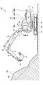
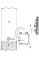
- FIG. 1 is a side view of an excavator 100 as an excavator according to this embodiment.
- the shovel 100 is located on a horizontal plane facing the uphill slope ES to be constructed, and is an upslope BS (that is, after construction on the uphill slope ES, which is an example of a target construction surface described later).
- the slope shape is also described.
- the shovel 100 includes a lower traveling body 1, an upper revolving body 3 that is mounted on the lower traveling body 1 so as to be rotatable via a revolving mechanism 2, a boom 4 and an arm that constitute an attachment (working machine). 5, a bucket 6, and a cabin 10.
- the lower traveling body 1 causes the excavator 100 to travel by hydraulically driving a pair of left and right crawlers by traveling hydraulic motors 1L and 1R. That is, the pair of traveling hydraulic motors 1L and 1R (an example of a traveling motor) drive the lower traveling body 1 (crawler) as a driven portion.
- traveling hydraulic motors 1L and 1R an example of a traveling motor
- the upper revolving structure 3 revolves with respect to the lower traveling structure 1 by being driven by the revolving hydraulic motor 2A. That is, the swing hydraulic motor 2A is a swing drive unit that drives the upper swing body 3 as a driven portion, and can change the direction of the upper swing body 3.
- the upper swing body 3 may be electrically driven by an electric motor (hereinafter, “swing electric motor”) instead of the swing hydraulic motor 2A.
- the revolving electric motor is a revolving drive unit that drives the upper revolving unit 3 as a non-driving unit, like the revolving hydraulic motor 2A, and can change the direction of the upper revolving unit 3.
- the boom 4 is pivotally attached to the center of the front part of the upper swing body 3 so that the boom 4 can be lifted up and down.
- An arm 5 is pivotally attached to the tip of the boom 4 so as to be vertically rotatable, and an end attachment is attached to the tip of the arm 5.
- the bucket 6 is pivotally attached so as to be vertically rotatable.
- the boom 4, the arm 5 and the bucket 6 are hydraulically driven by a boom cylinder 7, an arm cylinder 8 and a bucket cylinder 9 as hydraulic actuators, respectively.
- the bucket 6 is an example of an end attachment, and other end attachments, such as a slope bucket, a dredging bucket, and a breaker, may be provided at the tip of the arm 5 instead of the bucket 6, depending on the work content or the like. Etc. may be attached.
- the cabin 10 is an operator's cab in which an operator is boarded, and is mounted on the front left side of the upper swing body 3.
- the shovel 100 operates an actuator in response to an operation of an operator who rides in the cabin 10 to operate the operating elements (driven elements) such as the lower traveling body 1, the upper swing body 3, the boom 4, the arm 5, and the bucket 6. To drive.
- the operating elements driven elements
- the shovel 100 can be remotely operated by an operator of a predetermined external device (for example, a support device 200 or a management device 300 described later) instead of or in addition to being configured to be operated by the operator of the cabin 10. It may be configured as possible.
- the shovel 100 transmits, for example, image information (captured image) output by the image capturing apparatus S6 described below to an external device.
- image information captured image
- various information images displayed on the display device 40 of the shovel 100, which will be described later, may be similarly displayed on the display device provided in the external device.
- the operator can remotely operate the shovel 100, for example, while confirming the content displayed on the display device provided in the external device.
- the excavator 100 operates the actuator in accordance with a remote operation signal indicating the content of the remote operation received from the external device, and the lower traveling body 1, the upper swing body 3, the boom 4, the arm 5, and the bucket 6 are operated. Motion elements may be driven.
- the shovel 100 is remotely operated, the interior of the cabin 10 may be unattended.
- the description will be made on the assumption that the operator's operation includes at least one of the operation of the operator of the cabin 10 on the operation device 26 and the remote operation of the operator of the external device.
- the shovel 100 may automatically operate the hydraulic actuator regardless of the content of the operation of the operator.
- the shovel 100 has a function of automatically operating at least a part of operating elements such as the lower traveling body 1, the upper swing body 3, the boom 4, the arm 5, and the bucket 6 (hereinafter, referred to as an “automatic driving function” or “an automatic driving function”).
- Machine control function ”) is realized.
- the automatic driving function includes a function of automatically operating an operating element (hydraulic actuator) other than the operating element (hydraulic actuator) to be operated in response to an operation of the operating device 26 by an operator or a remote operation (so-called “semi-automatic operation function”). ) May be included. Further, the automatic driving function is a function of automatically operating at least a part of the plurality of driven elements (hydraulic actuators) on the assumption that the operator does not operate the operating device 26 or remote control (so-called “fully automatic driving function”). ) May be included. In the shovel 100, when the fully automatic driving function is effective, the inside of the cabin 10 may be unmanned.
- the automatic driving function allows the shovel 100 to recognize a gesture of a person such as an operator around the shovel 100, and at least a part of a plurality of driven elements (hydraulic actuators) depending on the content of the recognized gesture.
- a function for automatically operating the device (“gesture operation function”) may be included.
- the semi-automatic driving function, the fully automatic driving function, and the gesture operation function may include a mode in which the operation content of the operation element (hydraulic actuator) targeted for automatic operation is automatically determined according to a predetermined rule. ..
- the shovel 100 autonomously makes various judgments, and in accordance with the judgment result, the operation element (hydraulic actuator) that is the target of the autonomous driving autonomously.
- a mode in which the operation content of (3) is determined may be included.
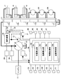
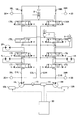
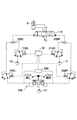
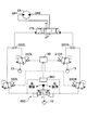
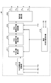
- FIGS. 2 and 3 are diagrams schematically showing an example of the configuration of the excavator 100 according to the present embodiment and another example, respectively.
- the shovel 100 of FIGS. 2 and 3 has the same configuration except that the configuration of a machine guidance unit 50, which will be described later, included in the controller 30 is different.
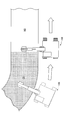
- FIG. 4 (FIGS. 4A and 4B) is a diagram showing a specific example of the relative positional relationship between the shovel 100 and the target construction surface.
- FIG. 4A is a diagram showing an example of a state in which the upper revolving superstructure 3 of the shovel 100 is not directly facing the target construction surface
- FIG. 4B is a diagram showing the upper revolving superstructure 3 of the shovel 100 on the target construction surface. It is a figure which shows an example of the state currently facing.
- the mechanical power system, the hydraulic oil line, the pilot line, and the electric control system are shown by a double line, a solid line, a broken line, and a dotted line, respectively.
- the construction completion area CS in the construction completion area CS, the construction of the target construction surface (for example, the upslope BS) in the construction target upslope surface ES is completed, that is, the target construction surface is completed.
- the non-constructed region NS represents a non-constructed region, that is, a region where the target construction surface is not completed.
- the cylindrical body CB is arranged so that its axis is along the normal direction to the target construction surface, and represents the normal direction of the target construction surface.
- the drive system of the shovel 100 includes an engine 11, a regulator 13, a main pump 14, and a control valve 17.
- the hydraulic drive system of the shovel 100 according to the present embodiment is, as described above, the traveling hydraulic motors 1L and 1R that hydraulically drive the lower traveling body 1, the upper swing body 3, the boom 4, the arm 5, and the bucket 6, respectively.
- a swing hydraulic motor 2A, a boom cylinder 7, an arm cylinder 8 and a bucket cylinder 9 are included.
- the engine 11 is a main power source in the hydraulic drive system, and is mounted on the rear part of the upper swing body 3, for example. Specifically, the engine 11 drives the main pump 14 and the pilot pump 15 under a direct or indirect control by the controller 30 described later to rotate at a constant target rotation speed.
- the engine 11 is, for example, a diesel engine that uses light oil as a fuel.
- the regulator 13 controls the discharge amount of the main pump 14. For example, the regulator 13 adjusts the angle (tilt angle) of the swash plate of the main pump 14 according to a control command from the controller 30.
- the regulator 13 includes, for example, regulators 13L and 13R as described later.
- the main pump 14 is mounted on the rear part of the upper swing body 3 and supplies hydraulic oil to the control valve 17 through the high-pressure hydraulic line.
- the main pump 14 is driven by the engine 11 as described above.
- the main pump 14 is, for example, a variable displacement hydraulic pump, and the stroke length of the piston is adjusted by adjusting the tilt angle of the swash plate by the regulator 13 under the control of the controller 30 as described above.
- the flow rate (discharge pressure) is controlled.
- the main pump 14 includes, for example, main pumps 14L and 14R as described later.
- the control valve 17 is, for example, a hydraulic control device that is mounted in the central portion of the upper swing body 3 and controls the hydraulic drive system according to an operator's operation of the operation device 26 or a remote operation. As described above, the control valve 17 is connected to the main pump 14 via the high-pressure hydraulic line, and controls the hydraulic oil supplied from the main pump 14 according to the state of the operation or remote operation of the operating device 26. It is selectively supplied to the traveling hydraulic motors 1L and 1R, the swing hydraulic motor 2A, the boom cylinder 7, the arm cylinder 8, and the bucket cylinder 9). Specifically, the control valve 17 includes control valves 171 to 176 that control the flow rate and the flowing direction of the hydraulic oil supplied from the main pump 14 to each hydraulic actuator.
- control valve 171 corresponds to the traveling hydraulic motor 1L
- control valve 172 corresponds to the traveling hydraulic motor 1R
- control valve 173 corresponds to the swing hydraulic motor 2A
- the control valve 174 corresponds to the bucket cylinder 9
- the control valve 175 corresponds to the boom cylinder 7
- the control valve 176 corresponds to the arm cylinder 8.
- the control valve 175 includes, for example, control valves 175L and 175R as described later
- control valve 176 includes, for example, control valves 176L and 176R as described later. Details of the control valves 171 to 176 will be described later (see FIG. 5).
- the operation system of the shovel 100 includes a pilot pump 15 and an operation device 26. Further, the operation system of the shovel 100 includes a shuttle valve 32 as a configuration related to the machine control function of the controller 30 described later.
- the pilot pump 15 is mounted, for example, at the rear of the upper swing body 3 and supplies pilot pressure to the operating device 26 via the pilot line.
- the pilot pump 15 is, for example, a fixed displacement hydraulic pump, and is driven by the engine 11 as described above.
- the operation device 26 is provided in the vicinity of the cockpit of the cabin 10 and is an operation input means for an operator to operate various operation elements (the lower traveling structure 1, the upper revolving structure 3, the boom 4, the arm 5, the bucket 6, etc.). Is. In other words, the operating device 26 operates the hydraulic actuators (that is, the traveling hydraulic motors 1L and 1R, the swing hydraulic motor 2A, the boom cylinder 7, the arm cylinder 8, the bucket cylinder 9, etc.) that the operator drives the respective operating elements. It is an operation input means for performing.
- the hydraulic actuators that is, the traveling hydraulic motors 1L and 1R, the swing hydraulic motor 2A, the boom cylinder 7, the arm cylinder 8, the bucket cylinder 9, etc.
- the operating device 26 is a hydraulic pilot type.
- the operating device 26 is connected to the control valve 17 either directly through the secondary pilot line or indirectly through a shuttle valve 32 (described later) provided in the secondary pilot line.
- a shuttle valve 32 described later
- the pilot pressure according to the operating state of the lower traveling body 1, the upper swing body 3, the boom 4, the arm 5, the bucket 6, and the like in the operating device 26 can be input to the control valve 17. Therefore, the control valve 17 can drive each hydraulic actuator according to the operating state of the operating device 26.
- the operation device 26 may be an electric type that outputs an electric signal (hereinafter, “operation signal”) corresponding to the operation content, instead of the hydraulic pilot type that outputs the pilot pressure.
- operation signal an electric signal from the operating device 26 is input to the controller 30, and the controller 30 controls each of the control valves 171 to 176 in the control valve 17 according to the input electric signal, thereby operating the operating device.
- the operation of various hydraulic actuators may be realized in accordance with the operation content of 26.
- the control valves 171 to 176 in the control valve 17 may be electromagnetic solenoid type spool valves driven by a command from the controller 30.
- a hydraulic control valve that operates according to an electric signal from the controller 30 (hereinafter, “operation control valve”) is arranged. May be.
- the operating control valve may be, for example, the proportional valve 31, and the shuttle valve 32 is omitted.
- the controller 30 controls the operation hydraulic control valve by an electric signal corresponding to the operation amount (for example, the lever operation amount) to control the pilot pressure. Increase or decrease.
- the controller 30 can operate each of the control valves 171 to 176 according to the operation content of the operation device 26.
- the operation control valve will be described on the assumption that it is the proportional valve 31.
- the operation device 26 includes, for example, a lever device that operates the arm 5 (arm cylinder 8). Further, the operating device 26 includes, for example, lever devices 26A to 26C for operating the boom 4 (boom cylinder 7), the bucket 6 (bucket cylinder 9), and the upper swing body 3 (swing hydraulic motor 2A), respectively (FIG. 6). reference). The operating device 26 also includes, for example, a lever device and a pedal device that operate each of the pair of left and right crawlers (running hydraulic motors 1L and 1R) of the lower traveling body 1.
- the shuttle valve 32 has two inlet ports and one outlet port, and outputs hydraulic oil having a pilot pressure higher than the pilot pressure input to the two inlet ports to the outlet port.
- One of the two inlet ports of the shuttle valve 32 is connected to the operating device 26, and the other is connected to the proportional valve 31.
- the outlet port of the shuttle valve 32 is connected to the pilot port of the corresponding control valve in the control valve 17 through the pilot line (see FIG. 4 for details). Therefore, shuttle valve 32 can cause the pilot pressure generated by operating device 26 or the pilot pressure generated by proportional valve 31 to be the higher one to act on the pilot port of the corresponding control valve.
- the controller 30 to be described later outputs a pilot pressure higher than the secondary side pilot pressure output from the operating device 26 from the proportional valve 31, so that the corresponding control is performed regardless of the operation of the operating device 26 by the operator.
- the valve can be controlled to control the operation of various operating elements.
- the shuttle valve 32 includes, for example, shuttle valves 32AL, 32AR, 32BL, 32BR, 32CL, 32CR, as described later.
- the control system of the shovel 100 includes a controller 30, a discharge pressure sensor 28, an operating pressure sensor 29, proportional valves 31, 33, a display device 40, an input device 42, and an audio output device 43.
- the controller 30 (an example of a control device) is provided in, for example, the cabin 10 and controls the drive of the shovel 100.
- the function of the controller 30 may be realized by any hardware, software, or a combination thereof.
- the controller 30 includes a memory device such as a CPU (Central Processing Unit) and a RAM (Random Access Memory), a nonvolatile auxiliary storage device such as a ROM (Read Only Memory), and an interface device for various input / output. It is mainly composed of a microcomputer.
- the controller 30 realizes various functions by executing various programs installed in a non-volatile auxiliary storage device on the CPU, for example.
- the controller 30 sets a target rotation speed based on a work mode or the like preset by a predetermined operation on the input device 42 by an operator or the like, and performs drive control to rotate the engine 11 at a constant speed.
- the controller 30 outputs a control command to the regulator 13 as necessary to change the discharge amount of the main pump 14.
- the controller 30 may control the proportional valve 31 to realize the operation of the hydraulic actuator according to the operation content of the operating device 26 as described above.
- the controller 30 may realize the remote control of the shovel 100 by using the proportional valve 31. Specifically, the controller 30 may output a control command corresponding to the content of the remote operation designated by the remote operation signal received from the external device to the proportional valve 31. Then, the proportional valve 31 outputs the pilot pressure corresponding to the control command from the controller 30, using the hydraulic oil supplied from the pilot pump 15, and outputs the pilot pressure to the pilot port of the corresponding control valve in the control valve 17. Pressure may be applied. As a result, the content of the remote operation is reflected in the operation of the control valve 17, and the operation of the various operation elements (driven elements) according to the content of the remote operation is realized by the hydraulic actuator.
- the controller 30 controls the peripheral monitoring function.
- the perimeter monitoring function monitors the entry of an object to be monitored into a predetermined range around the excavator 100 (hereinafter, “monitoring range”) based on the information acquired by the imaging device S6.
- the determination process of the entry of the monitoring target object into the monitoring range may be performed by the imaging device S6 or may be performed by the outside of the imaging device S6 (for example, the controller 30).
- Objects to be monitored may include, for example, people, trucks, other construction machinery, utility poles, suspended loads, pylons, buildings and the like.
- the controller 30 controls the object detection notification function.
- the object detection / informing function the presence of an object to be monitored with respect to the operator in the cabin 10 or the vicinity of the excavator 100 is notified when the peripheral monitoring function determines that an object to be monitored exists in the monitoring range.
- the controller 30 may realize the object detection notification function by using, for example, the display device 40 and the audio output device 43.
- the controller 30 controls the operation limiting function.
- the operation restriction function for example, the operation of the shovel 100 is restricted when the periphery monitoring function determines that an object to be monitored exists within the monitoring range.
- the monitoring target is a person will be mainly described.
- the controller 30 determines that an object to be monitored, such as a person, exists within a predetermined range (within the monitoring range) from the shovel 100 based on the information acquired by the imaging device S6 before the actuator operates, the controller 30 determines that the operator Even if the operating device 26 is operated, the operation of the actuator may be disabled or may be limited to the operation in the slow speed state. Specifically, when it is determined that a person is present within the monitoring range, the controller 30 can make the actuator inoperable by setting the gate lock valve in the locked state. In the case of the electric operating device 26, the actuator can be made inoperative by invalidating the signal from the controller 30 to the operating control valve (proportional valve 31).
- the pilot pressure corresponding to the control command from the controller 30 is output and the pilot pressure is applied to the pilot port of the corresponding control valve in the control valve 17 (control valve for operation (proportional valve).
- control valve for operation proportional valve
- 31 control valve for operation
- the control signal from the controller 30 to the operation control valve (proportional valve 31) is limited to a content corresponding to a relatively small pilot pressure, so that the operation of the actuator is at a very low speed.
- the actuator is not driven even if the operating device 26 is operated, or the operation speed corresponding to the operation input to the operating device 26.
- the actuator may be stopped by setting the gate lock valve in the locked state.
- controller 30 may naturally apply the same operation restriction function as in the case of operating the operating device 26 when the shovel 100 is remotely operated.
- the controller 30 controls, for example, a machine guidance function that guides the operator to manually operate the shovel 100.
- the controller 30 controls, for example, a machine control function that automatically supports a manual operation of the shovel 100 by an operator. That is, the controller 30 includes the machine guidance unit 50 as a functional unit related to the machine guidance function and the machine control function.
- controller 30 may be realized by another controller (control device). That is, the function of the controller 30 may be realized in a mode in which it is distributed by a plurality of controllers.
- the machine guidance function and the machine control function may be realized by a dedicated controller (control device).
- the discharge pressure sensor 28 detects the discharge pressure of the main pump 14. A detection signal corresponding to the discharge pressure detected by the discharge pressure sensor 28 is fetched by the controller 30.
- the discharge pressure sensor 28 includes, for example, discharge pressure sensors 28L and 28R as described later.
- the operation pressure sensor 29 operates the pilot pressure on the secondary side of the operation device 26, that is, the operation state (for example, the operation direction, the operation amount, etc.) related to each operating element (that is, the hydraulic actuator) of the operation device 26. Detect the pilot pressure corresponding to the operation content). The detection signal of the pilot pressure corresponding to the operation state of the lower traveling body 1, the upper swing body 3, the boom 4, the arm 5, the bucket 6, and the like in the operating device 26 by the operation pressure sensor 29 is fetched by the controller 30.
- the operation pressure sensor 29 includes operation pressure sensors 29A to 29C, for example, as described later.
- the operation pressure sensor 29 another sensor capable of detecting the operation state of each operating element of the operation device 26, for example, the operation amount (tilt amount) and the tilt direction of the lever devices 26A to 26C can be detected.
- An encoder, a potentiometer, or the like may be provided. Further, when the operating device 26 is an electric type, the operating pressure sensor 29 is omitted.
- the proportional valve 31 is provided in the pilot line that connects the pilot pump 15 and the shuttle valve 32.
- the proportional valve 31 is configured so that its flow passage area (cross-sectional area through which hydraulic oil can flow) can be changed, for example.
- the proportional valve 31 operates according to a control command input from the controller 30.
- the controller 30 controls the hydraulic oil discharged from the pilot pump 15 to the proportional valve 31 and the hydraulic oil. It can be supplied to the pilot port of the corresponding control valve in the control valve 17 via the shuttle valve 32.
- the proportional valve 31 includes, for example, proportional valves 31AL, 31AR, 31BL, 31BR, 31CL and 31CR, as described later.
- the proportional valve 33 is provided in the pilot line that connects the operating device 26 and the shuttle valve 32.
- the proportional valve 33 is configured so that its flow passage area can be changed, for example.
- the proportional valve 33 operates according to a control command input from the controller 30.
- the controller 30 can forcibly reduce the pilot pressure output from the operating device 26 when the operating device 26 (specifically, the lever devices 26A to 26C) is operated by the operator. .. Therefore, the controller 30 can forcibly suppress or stop the operation of the hydraulic actuator corresponding to the operation of the operating device 26 even when the operating device 26 is being operated. Further, for example, even when the operating device 26 is operated, the controller 30 can reduce the pilot pressure output from the operating device 26 to be lower than the pilot pressure output from the proportional valve 31.
- the controller 30 ensures that a desired pilot pressure is applied to the pilot port of the control valve in the control valve 17 regardless of the operation content of the operating device 26, for example. Can be operated. Therefore, the controller 30 can appropriately realize the automatic operation function and the remote operation function of the shovel 100 by controlling the proportional valve 33 in addition to the proportional valve 31, for example.
- the proportional valve 33 includes proportional valves 33AL, 33AR, 33BL, 33BR, 33CL and 33CR, as described later.
- the display device 40 is provided at a location in the cabin 10 where it can be easily seen by a seated operator, and displays various information images under the control of the controller 30.
- the display device 40 may be connected to the controller 30 via an in-vehicle communication network such as a CAN (Controller Area Network), or may be connected to the controller 30 via a one-to-one dedicated line.
- CAN Controller Area Network
- the input device 42 is provided within a reach of a seated operator in the cabin 10, receives various operation inputs from the operator, and outputs signals corresponding to the operation inputs to the controller 30.
- the input device 42 is a touch panel mounted on the display of the display device 40 that displays various information images, a knob switch provided at the tip of the lever portion of the lever devices 26A to 26C, a button switch installed around the display device 40, Includes levers, toggles, rotary dials, etc.
- a signal corresponding to the operation content of the input device 42 is fetched by the controller 30.
- the audio output device 43 is provided, for example, in the cabin 10, is connected to the controller 30, and outputs a predetermined sound under the control of the controller 30.
- the audio output device 43 is, for example, a speaker or a buzzer.
- the voice output device 43 outputs various kinds of information in response to a voice output command from the controller 30.
- the storage device 47 is provided in the cabin 10, for example, and stores various information under the control of the controller 30.
- the storage device 47 is, for example, a nonvolatile storage medium such as a semiconductor memory.
- the storage device 47 may store information output by various devices during the operation of the shovel 100, or may store information acquired via the various devices before the operation of the shovel 100 is started.
- the storage device 47 may store, for example, data regarding the target construction surface acquired via the communication device T1 or the like, or set via the input device 42 or the like.
- the target construction surface may be set (saved) by the operator of the shovel 100, or may be set by the construction manager or the like.
- the boom angle sensor S1 is attached to the boom 4, and the elevation angle of the boom 4 with respect to the upper swing body 3 (hereinafter, “boom angle”), for example, of the boom 4 with respect to the swing plane of the upper swing body 3 in a side view.
- the angle formed by the straight line connecting the fulcrums at both ends is detected.
- the boom angle sensor S1 may include, for example, a rotary encoder, an acceleration sensor, an angular velocity sensor, a 6-axis sensor, an IMU (Inertial Measurement Unit).
- the boom angle sensor S1 may include a potentiometer using a variable resistor, a cylinder sensor that detects the stroke amount of the hydraulic cylinder (boom cylinder 7) corresponding to the boom angle, and the like. The same applies to the arm angle sensor S2 and the bucket angle sensor S3.
- the detection signal corresponding to the boom angle from the boom angle sensor S1 is fetched by the controller 30.
- the arm angle sensor S2 is attached to the arm 5 and is a rotation angle of the arm 5 with respect to the boom 4 (hereinafter, “arm angle”), for example, the arm 5 with respect to a straight line connecting fulcrums at both ends of the boom 4 in a side view.
- arm angle a rotation angle of the arm 5 with respect to the boom 4
- the angle formed by the straight line connecting the fulcrums at both ends of is detected.
- the detection signal corresponding to the arm angle by the arm angle sensor S2 is fetched by the controller 30.
- the bucket angle sensor S3 is attached to the bucket 6 and rotates with respect to the arm 5 of the bucket 6 (hereinafter referred to as “bucket angle”), for example, the bucket 6 with respect to a straight line connecting fulcrums at both ends of the arm 5 in a side view.
- the angle formed by the straight line connecting the fulcrum and the tip (blade) is detected.
- the detection signal corresponding to the bucket angle by the bucket angle sensor S3 is fetched by the controller 30.
- the airframe inclination sensor S4 detects the inclination state of the airframe (the upper swing body 3 or the lower traveling body 1) with respect to the horizontal plane.
- the machine body tilt sensor S4 is attached to, for example, the upper swing body 3 and tilts about two axes of the shovel 100 (that is, the upper swing body 3) in the front-rear direction and the left-right direction (hereinafter, "front-back tilt angle” and "left-right tilt angle”). Tilt angle ").
- the machine body tilt sensor S4 may include, for example, a rotary encoder, an acceleration sensor, an angular velocity sensor, a 6-axis sensor, an IMU, and the like.
- the detection signals corresponding to the tilt angles (forward and backward tilt angles and left and right tilt angles) of the machine body tilt sensor S4 are fetched by the controller 30.
- the turning state sensor S5 outputs detection information regarding the turning state of the upper-part turning body 3.
- the turning state sensor S5 detects, for example, a turning angular velocity and a turning angle of the upper-part turning body 3.
- the turning state sensor S5 may include, for example, a gyro sensor, a resolver, a rotary encoder, and the like.
- the detection signal corresponding to the turning angle and the turning angular velocity of the upper turning body 3 by the turning state sensor S5 is fetched by the controller 30.
- the imaging device S6 images the area around the shovel 100.
- the imaging device S6 includes a camera S6F that images the front of the shovel 100, a camera S6L that images the left side of the shovel 100, a camera S6R that images the right side of the shovel 100, and a camera S6B that images the rear of the shovel 100. ..
- the camera S6F is mounted, for example, on the ceiling of the cabin 10, that is, inside the cabin 10.
- the camera S6F may be attached to the outside of the cabin 10, such as the roof of the cabin 10 or the side surface of the boom 4.
- the camera S6L is attached to, for example, the upper left end of the upper swing body 3, the camera S6R is attached to the upper right end of the upper swing body 3, and the camera S6B is attached to the upper rear end of the upper swing body 3, for example. Has been.
- the imaging device S6 is an example of a space recognition device that acquires information for recognizing the surroundings of the shovel 100.
- the imaging device S6 (cameras S6F, S6B, S6L, S6R) is, for example, a monocular wide-angle camera having a very wide angle of view. Further, the imaging device S6 may be a stereo camera, a distance image camera, or the like.
- the image captured by the image capturing device S6 is captured by the controller 30 via the display device 40.
- the imaging device S6 may also function as an object detection device that detects an object around the shovel 100 based on the acquired image information.
- the imaging device S6 may detect an object existing around the shovel 100.
- the object to be detected may include, for example, a person, an animal, a vehicle, a construction machine, a building, a hole, or the like.
- the imaging device S6 may calculate the distance from the imaging device S6 or the shovel 100 to the recognized object.
- the imaging device S6 as the object detection device may include, for example, a stereo camera, a distance image sensor, or the like.
- imaging device S6 for example, another space recognition device such as an ultrasonic sensor, a millimeter wave radar, a LIDAR (Light Detecting and Ranging), an infrared sensor, or an object detection device may be provided. Good.
- imaging device S6 may be directly connected to the controller 30 so as to be able to communicate therewith.
- the positioning device P1 measures the position and orientation of the upper swing body 3.
- the positioning device P1 is, for example, a GNSS (Global Navigation Satellite System) compass, detects the position and orientation of the upper swing body 3, and a detection signal corresponding to the position and orientation of the upper swing body 3 is captured by the controller 30. .. Further, among the functions of the positioning device P1, the function of detecting the orientation of the upper swing body 3 may be replaced by the azimuth sensor attached to the upper swing body 3.
- GNSS Global Navigation Satellite System
- the communication device T1 communicates with an external device through a predetermined network including a mobile communication network having a base station as a terminal, a satellite communication network, an internet network, and the like.
- the communication device T1 is, for example, a mobile communication module compatible with mobile communication standards such as LTE (Long Term Evolution), 4G (4th Generation), 5G (5th Generation), or satellite communication for connecting to a satellite communication network. Modules, etc.
- the machine guidance unit 50 executes, for example, control of the shovel 100 regarding the machine guidance function.
- the machine guidance unit 50 conveys work information such as the distance between the target construction surface and the tip of the attachment, specifically, the work site of the end attachment, to the operator through the display device 40, the voice output device 43, and the like. ..
- the data regarding the target construction surface is stored in advance in the storage device 47, for example, as described above.
- the data regarding the target construction surface is expressed in, for example, a reference coordinate system.
- the reference coordinate system is, for example, the world geodetic system.
- the World Geodetic System is a three-dimensional orthogonal system with the origin at the center of gravity of the earth, the X axis at the intersection of the Greenwich meridian and the equator, the Y axis at 90 degrees east longitude, and the Z axis at the North Pole. It is an XYZ coordinate system.
- the operator may set an arbitrary point on the construction site as a reference point, and set the target construction surface through the input device 42 based on the relative positional relationship with the reference point.
- the work site of the bucket 6 is, for example, the toe of the bucket 6 or the back surface of the bucket 6. Further, when, for example, a breaker is adopted as the end attachment instead of the bucket 6, the tip end of the breaker corresponds to the work site.
- the machine guidance unit 50 notifies the operator of work information through the display device 40, the voice output device 43, etc., and guides the operator to operate the shovel 100 through the operation device 26.
- the machine guidance unit 50 executes, for example, control of the excavator 100 regarding the machine control function.
- the machine guidance unit 50 for example, at least one of the boom 4, the arm 5, and the bucket 6 so that the target construction surface and the tip position of the bucket 6 match when the operator is manually performing the excavation operation. May operate automatically.
- the machine guidance unit 50 receives information from the boom angle sensor S1, the arm angle sensor S2, the bucket angle sensor S3, the body tilt sensor S4, the turning state sensor S5, the imaging device S6, the positioning device P1, the communication device T1, the input device 42, and the like. get. Then, the machine guidance unit 50 calculates, for example, the distance between the bucket 6 and the target construction surface based on the acquired information, and the bucket from the voice output from the voice output device 43 and the image displayed on the display device 40. 6 to notify the operator of the distance between the target construction surface and the tip of the attachment (specifically, the working portion such as the toe of the bucket 6 or the back surface) matches the target construction surface, Automatically control the movement of attachments.
- the machine guidance unit 50 includes a position calculation unit 51, a distance calculation unit 52, an information transmission unit 53, and an automatic control unit 54 as a detailed functional configuration related to the machine guidance function and the machine control function.
- the position calculation unit 51 calculates the position of a predetermined positioning target. For example, the position calculation unit 51 calculates the coordinate points in the reference coordinate system of the tip portion of the attachment, specifically, the work site such as the toes and the back surface of the bucket 6. Specifically, the position calculation unit 51 calculates the coordinate point of the work site of the bucket 6 from the elevation angles (boom angle, arm angle, and bucket angle) of the boom 4, the arm 5, and the bucket 6.
- the elevation angles boost angle, arm angle, and bucket angle
- the distance calculation unit 52 calculates the distance between two positioning targets. For example, the distance calculation unit 52 calculates the distance between the tip end portion of the attachment, specifically, the work site such as the toe or back surface of the bucket 6 and the target construction surface. Further, the distance calculation unit 52 may calculate an angle (relative angle) between the target construction surface and the back surface of the bucket 6 as a work site.
- the information transmitting unit 53 transmits (notifies) various information to the operator of the shovel 100 through a predetermined notifying means such as the display device 40 and the voice output device 43.
- the information transmission unit 53 notifies the operator of the shovel 100 of the magnitude (degree) of various distances calculated by the distance calculation unit 52.
- at least one of the visual information from the display device 40 and the auditory information from the audio output device 43 is used to notify the operator of the distance (size) between the tip of the bucket 6 and the target construction surface.
- the information transmitting unit 53 uses at least one of the visual information from the display device 40 and the auditory information from the audio output device 43 to determine the relative angle (the magnitude of the relative angle between the back surface of the bucket 6 as the work site and the target construction surface. May be transmitted to the operator.
- the information transmitting unit 53 uses the intermittent sound from the voice output device 43 to notify the operator of the magnitude of the distance (for example, the vertical distance) between the work site of the bucket 6 and the target construction surface.
- the information transmitting unit 53 may shorten the interval between the intermittent sounds as the vertical distance becomes shorter, and may increase the interval between the intermittent sounds as the vertical distance increases.
- the information transmitting unit 53 may use a continuous sound, or may indicate the difference in the vertical distance while changing the pitch, strength, etc. of the sound.
- the information transmitting unit 53 may issue an alarm through the voice output device 43 when the tip of the bucket 6 is located at a position lower than the target construction surface, that is, when it exceeds the target construction surface.
- the alarm is, for example, a continuous sound that is significantly louder than the intermittent sound.
- the information transmission unit 53 determines the distance between the tip of the attachment, specifically, the work site of the bucket 6 and the target construction surface, and the relative angle between the back surface of the bucket 6 and the target construction surface.
- the size and the like may be displayed on the display device 40 as work information.
- the display device 40 displays the work information received from the information transmission unit 53, for example, together with the image data received from the imaging device S6.
- the information transmission unit 53 may transmit the magnitude of the vertical distance to the operator by using, for example, an image of an analog meter or an image of a bar graph indicator.
- the automatic control unit 54 automatically supports the manual operation of the shovel 100 by the operator by automatically operating the actuator. Specifically, as described later, the automatic control unit 54 controls the control valves (specifically, the control valves) corresponding to the plurality of hydraulic actuators (specifically, the swing hydraulic motor 2A, the boom cylinder 7, and the bucket cylinder 9). The pilot pressures acting on control valve 173, control valves 175L, 175R, and 174) can be individually and automatically adjusted. Accordingly, the automatic control unit 54 can automatically operate each hydraulic actuator.
- the control related to the machine control function by the automatic control unit 54 may be executed, for example, when a predetermined switch included in the input device 42 is pressed.
- the predetermined switch is, for example, a machine control switch (hereinafter, “MC (Machine Control) switch”), and a grip portion by an operator of the operation device 26 (for example, a lever device corresponding to the operation of the arm 5) as a knob switch. It may be arranged at the tip of.
- MC Machine Control
- the following description will be given on the assumption that the machine control function is valid when the MC switch is pressed.
- the automatic control unit 54 automatically operates at least one of the boom cylinder 7 and the bucket cylinder 9 in accordance with the operation of the arm cylinder 8 in order to support excavation work and shaping work.
- the automatic control unit 54 when the operator manually performs the closing operation of the arm 5 (hereinafter, “arm closing operation”), the target construction surface and the work site such as the toe and the back surface of the bucket 6
- arm closing operation the closing operation of the arm 5
- At least one of the boom cylinder 7 and the bucket cylinder 9 is automatically expanded and contracted so that the position of the boom cylinder 7 and that of the bucket cylinder 9 match.
- the operator can close the arm 5 by simply closing the lever device corresponding to the operation of the arm 5 while closing the toe of the bucket 6 and the target construction surface.
- the automatic control unit 54 may automatically rotate the swing hydraulic motor 2A (an example of an actuator) in order to make the upper swing body 3 face the target construction surface. ..
- the control by the controller 30 (automatic control unit 54) to make the upper revolving superstructure 3 face the target construction surface will be referred to as “face-up control”.
- face-up control the control by the controller 30 (automatic control unit 54) to make the upper revolving superstructure 3 face the target construction surface.
- face-up control the operator or the like can perform the target construction of the upper revolving structure 3 simply by pressing a predetermined switch, or by operating a lever device 26C, which will be described later, corresponding to the turning operation while the switch is being pressed. You can face the surface. Further, the operator can make the upper swing body 3 face the target construction surface and start the machine control function relating to the excavation work of the target construction surface and the like just by pressing the MC switch.
- the tip of the attachment (for example, the toe or the back surface as the working portion of the bucket 6) is attached to the target construction surface according to the operation of the attachment.
- This is a state in which it can be moved along the inclination direction of the upslope BS).
- an attachment operating surface (attachment operating surface) AF perpendicular to the turning plane SF of the excavator 100. Is a state including the normal line of the target construction surface corresponding to the cylindrical body CB (in other words, a state along the normal line).
- the tip of the attachment should move the target construction surface in the tilt direction. I can't. Therefore, as a result, the shovel 100 cannot properly construct the target construction surface.
- the automatic control unit 54 can cause the upper-part turning body 3 to face directly by automatically rotating the turning hydraulic motor 2A as shown in FIG. 4B. As a result, the shovel 100 can appropriately construct the target construction surface.
- the automatic control unit 54 determines, for example, a vertical distance between the coordinate point at the left end of the toe of the bucket 6 and the target construction surface (hereinafter, “vertical distance at the left end”) and a right end of the toe of the bucket 6.
- vertical distance at the left end a vertical distance between the coordinate point at the left end of the toe of the bucket 6 and the target construction surface
- right end vertical distance a vertical distance between the coordinate points and the target construction surface
- the automatic control unit 54 does not determine that the left end vertical distance is equal to the right end vertical distance (that is, the difference between the left end vertical distance and the right end vertical distance is zero), but the difference is equal to or less than a predetermined value.
- it becomes it may be determined that the shovel 100 is facing the target construction surface.
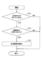
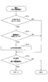
- the automatic control unit 54 may operate the swing hydraulic motor 2A in the facing control, for example, based on the difference between the left end vertical distance and the right end vertical distance. Specifically, when the lever device 26C corresponding to the turning operation is operated while a predetermined switch such as the MC switch is pressed down, the lever device 26C is moved in the direction in which the upper-part turning body 3 faces the target construction surface. It is determined whether or not it has been operated. For example, when the lever device 26C is operated in a direction in which the vertical distance between the toe of the bucket 6 and the target construction surface (up slope) increases, the automatic control unit 54 does not execute the facing control.
- the automatic control unit 54 executes the facing control.
- the automatic control unit 54 can operate the swing hydraulic motor 2A so that the difference between the left end vertical distance and the right end vertical distance becomes small.
- the automatic control unit 54 stops the swing hydraulic motor 2A.
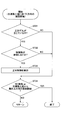
- the automatic control unit 54 sets a turning angle at which the difference is equal to or less than a predetermined value or becomes zero as a target angle, and the target angle and the current turning angle (specifically, based on the detection signal of the turning state sensor S5).
- the operation control of the swing hydraulic motor 2A may be performed so that the angle difference from the detected value) becomes zero.
- the turning angle is, for example, the angle of the front-rear axis of the upper turning body 3 with respect to the reference direction.
- the automatic control unit 54 performs the facing control with the turning electric motor (an example of the actuator) as a control target. ..
- the machine guidance unit 50 may further include a turning angle calculation unit 55 and a relative angle calculation unit 56.
- the turning angle calculation unit 55 calculates the turning angle of the upper turning body 3. Thereby, the controller 30 can specify the current orientation of the upper swing body 3.
- the turning angle calculation unit 55 calculates, for example, the angle of the front-rear axis of the upper turning body 3 with respect to the reference direction as the turning angle based on the output signal of the GNSS compass included in the positioning device P1. Further, the turning angle calculation unit 55 may calculate the turning angle based on the detection signal of the turning state sensor S5. When the reference point is set at the construction site, the turning angle calculation unit 55 may set the direction in which the reference point is viewed from the turning axis as the reference direction.
- the turning angle indicates the direction in which the attachment operating surface extends with respect to the reference direction.
- the attachment operating surface is, for example, a virtual plane that vertically cuts the attachment, and is arranged so as to be perpendicular to the turning plane.
- the turning plane is, for example, an imaginary plane including the bottom surface of the turning frame perpendicular to the turning axis. For example, when the controller 30 (machine guidance unit 50) determines that the attachment operation surface includes the normal line of the target construction surface, the controller 30 determines that the upper swing body 3 faces the target construction surface.
- the relative angle calculation unit 56 calculates the turning angle (relative angle) required to make the upper-part turning body 3 face the target construction surface.
- the relative angle is formed, for example, between the direction of the front-rear axis of the upper revolving structure 3 when the upper revolving structure 3 faces the target construction surface and the current direction of the front-rear axis of the upper revolving structure 3. It is a relative angle.
- the relative angle calculation unit 56 calculates the relative angle based on, for example, the data regarding the target construction surface stored in the storage device 47 and the turning angle calculated by the turning angle calculation unit 55.
- the automatic control unit 54 When the lever device 26C corresponding to the turning operation is operated while a predetermined switch such as the MC switch is pressed down, the automatic control unit 54 is turned in a direction in which the upper-part turning body 3 faces the target construction surface. Judge whether or not. When the automatic control unit 54 determines that the upper revolving structure 3 has been swung in the direction to face the target construction surface, the automatic control unit 54 sets the relative angle calculated by the relative angle calculation unit 56 as the target angle. When the change in the turning angle after the lever device 26C is operated reaches the target angle, the automatic control unit 54 determines that the upper-part turning body 3 faces the target construction surface, and the turning hydraulic motor 2A operates. You may stop the movement. Thereby, the automatic control unit 54 can make the upper swing body 3 face the target construction surface directly on the premise of the configuration shown in FIG. 3.
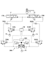
- FIG. 5 is a diagram schematically showing an example of the configuration of the hydraulic system of the shovel 100 according to the present embodiment.
- the hydraulic system realized by the hydraulic circuit circulates the hydraulic oil from each of the main pumps 14L and 14R driven by the engine 11 to the hydraulic oil tank via the center bypass oil passages C1L and C1R and the parallel oil passages C2L and C2R.
- the center bypass oil passage C1L starts from the main pump 14L and sequentially passes through the control valves 171, 173, 175L, 176L arranged in the control valve 17, and reaches the hydraulic oil tank.
- the center bypass oil passage C1R starts from the main pump 14R and sequentially passes through the control valves 172, 174, 175R and 176R arranged in the control valve 17, and reaches the hydraulic oil tank.
- the control valve 171 is a spool valve that supplies the hydraulic oil discharged from the main pump 14L to the traveling hydraulic motor 1L and discharges the hydraulic oil discharged by the traveling hydraulic motor 1L to the hydraulic oil tank.
- the control valve 172 is a spool valve that supplies the hydraulic oil discharged from the main pump 14R to the traveling hydraulic motor 1R and discharges the hydraulic oil discharged by the traveling hydraulic motor 1R to the hydraulic oil tank.
- the control valve 173 is a spool valve that supplies the hydraulic oil discharged from the main pump 14L to the swing hydraulic motor 2A and discharges the hydraulic oil discharged by the swing hydraulic motor 2A to the hydraulic oil tank.
- the control valve 174 is a spool valve that supplies the hydraulic oil discharged from the main pump 14R to the bucket cylinder 9 and discharges the hydraulic oil in the bucket cylinder 9 to the hydraulic oil tank.
- the control valves 175L and 175R are spool valves that supply the hydraulic oil discharged from the main pumps 14L and 14R to the boom cylinder 7 and discharge the hydraulic oil in the boom cylinder 7 to the hydraulic oil tank.
- the control valves 176L and 176R respectively supply the hydraulic oil discharged by the main pumps 14L and 14R to the arm cylinder 8 and discharge the hydraulic oil in the arm cylinder 8 to the hydraulic oil tank.
- the control valves 171, 172, 173, 174, 175L, 175R, 176L, 176R respectively adjust the flow rate of the hydraulic oil supplied to and discharged from the hydraulic actuator according to the pilot pressure acting on the pilot port, and the flow direction. To switch.
- the parallel oil passage C2L supplies the hydraulic oil of the main pump 14L to the control valves 171, 173, 175L, 176L in parallel with the center bypass oil passage C1L.
- the parallel oil passage C2L branches from the center bypass oil passage C1L on the upstream side of the control valve 171, and supplies the hydraulic oil of the main pump 14L in parallel to each of the control valves 171, 173, 175L, and 176R. Configured to be possible.
- the parallel oil passage C2L supplies the working oil to the control valve further downstream when the flow of the working oil passing through the center bypass oil passage C1L is restricted or cut off by any of the control valves 171, 173, 175L. it can.
- the parallel oil passage C2R supplies the working oil of the main pump 14R to the control valves 172, 174, 175R, 176R in parallel with the center bypass oil passage C1R.
- the parallel oil passage C2R branches from the center bypass oil passage C1R on the upstream side of the control valve 172, and supplies the hydraulic oil of the main pump 14R in parallel to each of the control valves 172, 174, 175R, and 176R. Configured to be possible.
- the parallel oil passage C2R can supply the working oil to the control valve on the further downstream side when the flow of the working oil passing through the center bypass oil passage C1R is restricted or interrupted by any of the control valves 172, 174, 175R.
- the regulators 13L and 13R adjust the discharge amounts of the main pumps 14L and 14R by adjusting the tilt angles of the swash plates of the main pumps 14L and 14R.
- the discharge pressure sensor 28L detects the discharge pressure of the main pump 14L, and a detection signal corresponding to the detected discharge pressure is fetched by the controller 30. The same applies to the discharge pressure sensor 28R. As a result, the controller 30 can control the regulators 13L and 13R according to the discharge pressures of the main pumps 14L and 14R.
- negative control throttles 18L and 18R are provided between the most downstream control valves 176L and 176R and the hydraulic oil tank.
- negative control throttles 18L and 18R generate control pressure (hereinafter, “negative control pressure") for controlling the regulators 13L and 13R.
- the negative control pressure sensors 19L and 19R detect the negative control pressure, and a detection signal corresponding to the detected negative control pressure is fetched by the controller 30.
- the controller 30 may control the regulators 13L and 13R according to the discharge pressures of the main pumps 14L and 14R detected by the discharge pressure sensors 28L and 28R, and adjust the discharge amounts of the main pumps 14L and 14R. For example, the controller 30 may decrease the discharge amount by controlling the regulator 13L and adjusting the swash plate tilt angle of the main pump 14L according to the increase in the discharge pressure of the main pump 14L. The same applies to the regulator 13R. As a result, the controller 30 controls the total horsepower of the main pumps 14L and 14R so that the absorbed horsepower of the main pumps 14L and 14R represented by the product of the discharge pressure and the discharge amount does not exceed the output horsepower of the engine 11. be able to.
- the controller 30 may adjust the discharge amount of the main pumps 14L, 14R by controlling the regulators 13L, 13R according to the negative control pressures detected by the negative control pressure sensors 19L, 19R. For example, the controller 30 decreases the discharge amount of the main pumps 14L and 14R as the negative control pressure increases, and increases the discharge amount of the main pumps 14L and 14R as the negative control pressure decreases.
- the hydraulic oil discharged from the main pumps 14L and 14R flows through the center bypass oil passages C1L and C1R. It passes through to the negative control diaphragms 18L and 18R.
- the flow of hydraulic oil discharged from the main pumps 14L and 14R increases the negative control pressure generated upstream of the negative control throttles 18L and 18R.
- the controller 30 reduces the discharge amount of the main pumps 14L and 14R to the allowable minimum discharge amount, and suppresses the pressure loss (pumping loss) when the discharged hydraulic oil passes through the center bypass oil passages C1L and C1R. ..
- the hydraulic oil discharged from the main pumps 14L and 14R flows into the operation target hydraulic actuator via the control valve corresponding to the operation target hydraulic actuator. Then, the flow of the hydraulic oil discharged from the main pumps 14L, 14R reduces or disappears the amount reaching the negative control throttles 18L, 18R, and lowers the negative control pressure generated upstream of the negative control throttles 18L, 18R. As a result, the controller 30 can increase the discharge amounts of the main pumps 14L and 14R, circulate sufficient hydraulic oil in the operation target hydraulic actuator, and reliably drive the operation target hydraulic actuator.
- FIG. 6A to 6C are diagrams schematically showing an example of components of an operation system relating to the boom 4, the bucket 6, and the upper swing body 3 in the hydraulic system of the shovel 100 according to the present embodiment.
- FIG. 6A is a diagram showing an example of a pilot circuit that applies pilot pressure to the control valves 175L and 175R that hydraulically control the boom cylinder 7.
- FIG. 6B is a diagram showing an example of a pilot circuit that applies pilot pressure to the control valve 174 that hydraulically controls the bucket cylinder 9.
- FIG. 6C is a diagram showing an example of a pilot circuit that applies pilot pressure to the control valve 173 that hydraulically controls the swing hydraulic motor 2A.
- the lever device 26A is used by an operator or the like to operate the boom cylinder 7 corresponding to the boom 4.
- the lever device 26A uses the hydraulic oil discharged from the pilot pump 15 to output the pilot pressure according to the operation content to the secondary side.
- the shuttle valve 32AL has two inlet ports corresponding to an operation in the raising direction of the boom 4 (hereinafter, "boom raising operation"), a pilot line on the secondary side of the lever device 26A, and a secondary valve of the proportional valve 31AL. Connected to the pilot line on the side, and the outlet port is connected to the pilot port on the right side of the control valve 175L and the pilot port on the left side of the control valve 175R.
- boom raising operation an operation in the raising direction of the boom 4
- pilot line on the secondary side of the lever device 26A Connected to the pilot line on the side, and the outlet port is connected to the pilot port on the right side of the control valve 175L and the pilot port on the left side of the control valve 175R.
- the two inlet ports respectively correspond to the operation of the boom 4 in the lowering direction (hereinafter, "boom lowering operation"), the pilot line on the secondary side of the lever device 26A, and the secondary valve of the proportional valve 31AR. Connected to the pilot line on the side, and the outlet port is connected to the pilot port on the right side of the control valve 175R.
- the lever device 26A causes the pilot pressure corresponding to the operation content (for example, the operation direction and the operation amount) to act on the pilot ports of the control valves 175L and 175R via the shuttle valves 32AL and 32AR.
- the lever device 26A outputs a pilot pressure corresponding to the operation amount to one inlet port of the shuttle valve 32AL, and the shuttle valve 32AL is used to output the pilot pressure to the right side of the control valve 175L. And the pilot port on the left side of the control valve 175R.
- the lever device 26A when the boom device is operated to lower the boom, the lever device 26A outputs a pilot pressure corresponding to the operation amount to one inlet port of the shuttle valve 32AR, and via the shuttle valve 32AR, the pilot port on the right side of the control valve 175R. To act on.
- the proportional valve 31AL operates according to the control current input from the controller 30. Specifically, the proportional valve 31AL uses the hydraulic oil discharged from the pilot pump 15 to output the pilot pressure according to the control current input from the controller 30 to the other inlet port of the shuttle valve 32AL. As a result, the proportional valve 31AL can adjust the pilot pressure acting on the pilot port on the right side of the control valve 175L and the pilot port on the left side of the control valve 175R via the shuttle valve 32AL.
- the proportional valve 31AR operates according to the control current input from the controller 30. Specifically, the proportional valve 31AR outputs the pilot pressure according to the control current input from the controller 30 to the other inlet port of the shuttle valve 32AR by using the hydraulic oil discharged from the pilot pump 15. Thereby, the proportional valve 31AR can adjust the pilot pressure acting on the pilot port on the right side of the control valve 175R via the shuttle valve 32AR.
- the proportional valves 31AL and 31AR can adjust the pilot pressure output to the secondary side so that the control valves 175L and 175R can be stopped at arbitrary valve positions regardless of the operating state of the lever device 26A.
- the proportional valve 33AL operates according to the control current input from the controller 30. Specifically, when the control current from the controller 30 is not input, the proportional valve 33AL outputs the pilot pressure corresponding to the boom raising operation of the lever device 26A to the secondary side as it is. On the other hand, when the control current from the controller 30 is input, the proportional valve 33AL reduces the pilot pressure of the pilot line on the secondary side corresponding to the boom raising operation of the lever device 26A to an extent according to the control current, and reduces the pressure. The pilot pressure is output to one inlet port of the shuttle valve 32AL.
- the proportional valve 33AL forcibly suppresses or stops the operation of the boom cylinder 7 corresponding to the boom raising operation, if necessary, even when the boom raising operation is being performed by the lever device 26A. It can be done. Further, the proportional valve 33AL changes the pilot pressure acting on one inlet port of the shuttle valve 32AL from the proportional valve 31AL to the other inlet of the shuttle valve 32AL even when the boom raising operation is performed by the lever device 26A. It can be lower than the pilot pressure acting on the port. Therefore, the controller 30 can control the proportional valve 31AL and the proportional valve 33AL to reliably apply a desired pilot pressure to the boom raising side pilot ports of the control valves 175L and 175R.
- the proportional valve 33AR operates according to the control current input from the controller 30. Specifically, when the control current from the controller 30 is not input, the proportional valve 33AR outputs the pilot pressure corresponding to the boom lowering operation of the lever device 26A to the secondary side as it is. On the other hand, when the control current from the controller 30 is input, the proportional valve 33AR reduces the pilot pressure in the pilot line on the secondary side corresponding to the boom lowering operation of the lever device 26A to a degree corresponding to the control current, and reduces the pressure. The pilot pressure is output to one inlet port of the shuttle valve 32AR.
- the proportional valve 33AR forcibly suppresses or stops the operation of the boom cylinder 7 corresponding to the boom lowering operation as necessary, even when the boom lowering operation is being performed by the lever device 26A. It can be done. Further, the proportional valve 33AR changes the pilot pressure acting on one inlet port of the shuttle valve 32AR from the proportional valve 31AR to the other inlet of the shuttle valve 32AR even when the boom lowering operation is performed by the lever device 26A. It can be lower than the pilot pressure acting on the port. Therefore, the controller 30 can control the proportional valve 31AR and the proportional valve 33AR to surely apply a desired pilot pressure to the boom lowering pilot ports of the control valves 175L and 175R.
- the proportional valves 33AL and 33AR can forcibly suppress or stop the operation of the boom cylinder 7 corresponding to the operating state of the lever device 26A. Further, the proportional valves 33AL, 33AR reduce the pilot pressure acting on one inlet port of the shuttle valves 32AL, 32AR, and the pilot pressures of the proportional valves 31AL, 31AR are reliably controlled through the shuttle valves 32AL, 32AR to the control valves 175L, 175R. Can be assisted to act on the pilot port.
- the controller 30 controls the proportional valve 31AR instead of controlling the proportional valve 33AL to forcibly suppress or stop the operation of the boom cylinder 7 corresponding to the boom raising operation of the lever device 26A. May be.
- the controller 30 controls the proportional valve 31AR when a boom raising operation is performed by the lever device 26A, and the proportional valve 31AR is provided to the pilot ports on the boom lowering side of the control valves 175L and 175R via the shuttle valve 32AR. Pilot pressure may be applied.
- the pilot device controls the pilot valves to the boom lowering pilot ports of the control valves 175L and 175R so as to oppose the pilot pressure acting on the boom raising side pilot ports of the control valves 175L and 175R from the lever device 26A via the shuttle valve 32AL. Pressure acts. Therefore, the controller 30 can force the control valves 175L and 175R to approach the neutral position to suppress or stop the operation of the boom cylinder 7 corresponding to the boom raising operation of the lever device 26A. Similarly, the controller 30 controls the proportional valve 31AL instead of controlling the proportional valve 33AR to forcibly suppress or stop the operation of the boom cylinder 7 corresponding to the boom lowering operation of the lever device 26A. You may.
- the operation pressure sensor 29A detects the operation content of the lever device 26A by the operator in the form of pressure (operation pressure), and a detection signal corresponding to the detected pressure is taken into the controller 30. Thereby, the controller 30 can grasp the operation content with respect to the lever device 26A.
- the controller 30 controls the hydraulic fluid discharged from the pilot pump 15 via the proportional valve 31AL and the shuttle valve 32AL, regardless of the boom raising operation of the lever device 26A by the operator, and the pilot port on the right side of the control valve 175L. It can be supplied to the pilot port on the left side of the valve 175R. Further, the controller 30 causes the hydraulic oil discharged from the pilot pump 15 to flow through the proportional valve 31AR and the shuttle valve 32AR to the pilot port on the right side of the control valve 175R, regardless of the boom lowering operation of the lever device 26A by the operator. Can be supplied to. That is, the controller 30 can automatically control the raising and lowering operation of the boom 4 and realize the automatic operation function and the remote operation function of the shovel 100.
- the lever device 26B is used by an operator or the like to operate the bucket cylinder 9 corresponding to the bucket 6.
- the lever device 26B uses the hydraulic oil discharged from the pilot pump 15 to output the pilot pressure according to the operation content to the secondary side.
- the two inlet ports respectively correspond to the operation in the closing direction of the bucket 6 (hereinafter, “bucket closing operation"), the pilot line on the secondary side of the lever device 26B, and the secondary valve of the proportional valve 31BL. Connected to the pilot line on the side, and the outlet port is connected to the pilot port on the left side of the control valve 174.
- the two inlet ports respectively correspond to the operation in the opening direction of the bucket 6 (hereinafter, “bucket opening operation"), the pilot line on the secondary side of the lever device 26B, and the secondary valve of the proportional valve 31BR. Connected to the pilot line on the side, and the outlet port is connected to the pilot port on the right side of the control valve 174.
- the lever device 26B causes the pilot pressure according to the operation content to act on the pilot port of the control valve 174 via the shuttle valves 32BL and 32BR. Specifically, when the bucket device is closed, the lever device 26B outputs a pilot pressure corresponding to the operation amount to one inlet port of the shuttle valve 32BL, and the left side of the control valve 174 is left via the shuttle valve 32BL. Act on the pilot port of. Further, when the bucket device is operated to open, the lever device 26B outputs the pilot pressure according to the operation amount to one inlet port of the shuttle valve 32BR, and via the shuttle valve 32BR, the pilot port on the right side of the control valve 174. To act on.
- the proportional valve 31BL operates according to the control current input from the controller 30. Specifically, the proportional valve 31BL outputs the pilot pressure corresponding to the control current input from the controller 30 to the other pilot port of the shuttle valve 32BL using the hydraulic oil discharged from the pilot pump 15. Accordingly, the proportional valve 31BL can adjust the pilot pressure acting on the pilot port on the left side of the control valve 174 via the shuttle valve 32BL.
- the proportional valve 31BR operates according to the control current output by the controller 30. Specifically, the proportional valve 31BR outputs the pilot pressure corresponding to the control current input from the controller 30 to the other pilot port of the shuttle valve 32BR using the hydraulic oil discharged from the pilot pump 15. Accordingly, the proportional valve 31BR can adjust the pilot pressure acting on the pilot port on the right side of the control valve 174 via the shuttle valve 32BR.
- the proportional valves 31BL and 31BR can adjust the pilot pressure output to the secondary side so that the control valve 174 can be stopped at any valve position regardless of the operating state of the lever device 26B.
- the proportional valve 33BL operates according to the control current input from the controller 30. Specifically, when the control current from the controller 30 is not input, the proportional valve 33BL outputs the pilot pressure corresponding to the bucket closing operation of the lever device 26B to the secondary side as it is. On the other hand, when the control current from the controller 30 is input, the proportional valve 33BL reduces the pilot pressure of the pilot line on the secondary side corresponding to the bucket closing operation of the lever device 26B to a degree according to the control current, and reduces the pressure. The pilot pressure is output to one inlet port of the shuttle valve 32BL.
- the proportional valve 33BL forcibly suppresses or stops the operation of the bucket cylinder 9 corresponding to the bucket closing operation, if necessary, even when the bucket closing operation is performed by the lever device 26B. It can be done. Further, the proportional valve 33BL changes the pilot pressure acting on one inlet port of the shuttle valve 32BL from the proportional valve 31BL to the other inlet of the shuttle valve 32BL even when the bucket device is closed by the lever device 26B. It can be lower than the pilot pressure acting on the port. Therefore, the controller 30 can control the proportional valve 31BL and the proportional valve 33BL to surely apply a desired pilot pressure to the bucket closing side pilot port of the control valve 174.
- the proportional valve 33BR operates according to the control current input from the controller 30. Specifically, when the control current from the controller 30 is not input, the proportional valve 33BR outputs the pilot pressure corresponding to the bucket opening operation of the lever device 26B to the secondary side as it is. On the other hand, when the control current from the controller 30 is input, the proportional valve 33BR reduces the pilot pressure of the pilot line on the secondary side corresponding to the bucket opening operation of the lever device 26B to an extent corresponding to the control current, and reduces the pressure. The pilot pressure is output to one inlet port of the shuttle valve 32BR.
- the proportional valve 33BR forcibly suppresses or stops the operation of the bucket cylinder 9 corresponding to the bucket opening operation, if necessary, even when the bucket opening operation is being performed by the lever device 26B. It can be done. Further, the proportional valve 33BR applies the pilot pressure acting on one inlet port of the shuttle valve 32BR from the proportional valve 31BR to the other inlet of the shuttle valve 32BR even when the bucket device is operated to open the bucket by the lever device 26B. It can be lower than the pilot pressure acting on the port. Therefore, the controller 30 can control the proportional valve 31BR and the proportional valve 33BR to surely apply a desired pilot pressure to the bucket opening side pilot port of the control valve 174.
- the proportional valves 33BL and 33BR can forcibly suppress or stop the operation of the bucket cylinder 9 corresponding to the operating state of the lever device 26B. Further, the proportional valves 33BL, 33BR reduce the pilot pressure acting on one inlet port of the shuttle valves 32BL, 32BR, and the pilot pressures of the proportional valves 31BL, 31BR are reliably ensured via the shuttle valves 32BL, 32BR. Can assist in acting on the port.
- the controller 30 controls the proportional valve 31BR instead of controlling the proportional valve 33BL to forcibly suppress or stop the operation of the bucket cylinder 9 corresponding to the bucket closing operation of the lever device 26B. May be.
- the controller 30 controls the proportional valve 31BR when a bucket closing operation is performed by the lever device 26B, and the proportional valve 31BR via the shuttle valve 32BR to the pilot port on the bucket opening side of the control valve 174 provides a predetermined pilot. Pressure may be applied.
- the pilot pressure acts on the bucket opening side pilot port of the control valve 174 in a manner that opposes the pilot pressure acting on the bucket closing side pilot port of the control valve 174 from the lever device 26B via the shuttle valve 32BL. ..
- the controller 30 can forcibly bring the control valve 174 close to the neutral position to suppress or stop the operation of the bucket cylinder 9 corresponding to the bucket closing operation of the lever device 26B.
- the controller 30 controls the proportional valve 31BL instead of controlling the proportional valve 33BR to forcibly suppress or stop the operation of the bucket cylinder 9 corresponding to the bucket opening operation of the lever device 26B. You may.
- the operation pressure sensor 29B detects the operation content of the lever device 26B by the operator in the form of pressure (operation pressure), and a detection signal corresponding to the detected pressure is fetched by the controller 30. Thereby, the controller 30 can grasp the operation content of the lever device 26B.
- the controller 30 supplies the hydraulic oil discharged from the pilot pump 15 to the pilot port on the left side of the control valve 174 via the proportional valve 31BL and the shuttle valve 32BL, regardless of the bucket closing operation of the lever device 26B by the operator. Can be made Further, the controller 30 causes the hydraulic oil discharged from the pilot pump 15 to flow through the proportional valve 31BR and the shuttle valve 32BR to the pilot port on the right side of the control valve 174 regardless of the bucket opening operation of the lever device 26B by the operator. Can be supplied to. That is, the controller 30 can automatically control the opening / closing operation of the bucket 6 and realize the automatic operation function, the remote operation function, and the like of the shovel 100.
- the lever device 26C is used by an operator or the like to operate the swing hydraulic motor 2A corresponding to the upper swing body 3 (swing mechanism 2).
- the lever device 26C uses the hydraulic oil discharged from the pilot pump 15 to output the pilot pressure according to the operation content to the secondary side.
- the shuttle valve 32CL has two inlet ports respectively corresponding to a leftward turning operation of the upper swing body 3 (hereinafter, "left turning operation"), a pilot line on the secondary side of the lever device 26C, and a proportional valve 31CL. Of the control valve 173, and the outlet port thereof is connected to the pilot port on the left side of the control valve 173.
- the shuttle valve 32CR has two inlet ports, respectively, a pilot line on the secondary side of the lever device 26C that corresponds to a rightward swing operation of the upper swing body 3 (hereinafter, "right swing operation"), and a proportional valve. It is connected to the pilot line on the secondary side of 31CR, and the outlet port is connected to the pilot port on the right side of control valve 173.
- the lever device 26C causes the pilot pressure of the control valve 173 to act on the pilot port according to the operation content via the shuttle valves 32CL and 32CR. Specifically, when the lever device 26C is operated to turn left, the lever device 26C outputs a pilot pressure corresponding to the operation amount to one inlet port of the shuttle valve 32CL, and the left side of the control valve 173 via the shuttle valve 32CL. Act on the pilot port of. Further, when the lever device 26C is turned rightward, the lever device 26C outputs a pilot pressure corresponding to the operation amount to one inlet port of the shuttle valve 32CR, and the right pilot of the control valve 173 is supplied via the shuttle valve 32CR. Act on the port.
- the proportional valve 31CL operates according to the control current input from the controller 30. Specifically, the proportional valve 31CL outputs the pilot pressure according to the control current input from the controller 30 to the other pilot port of the shuttle valve 32CL using the hydraulic oil discharged from the pilot pump 15. As a result, the proportional valve 31CL can adjust the pilot pressure acting on the pilot port on the left side of the control valve 173 via the shuttle valve 32CL.
- the proportional valve 31CR operates according to the control current output by the controller 30. Specifically, the proportional valve 31CR outputs the pilot pressure corresponding to the control current input from the controller 30 to the other pilot port of the shuttle valve 32CR using the hydraulic oil discharged from the pilot pump 15. Thereby, the proportional valve 31CR can adjust the pilot pressure acting on the pilot port on the right side of the control valve 173 via the shuttle valve 32CR.
- the proportional valves 31CL and 31CR can adjust the pilot pressure output to the secondary side so that the control valve 173 can be stopped at any valve position regardless of the operating state of the lever device 26C.
- the proportional valve 33CL operates according to the control current input from the controller 30. Specifically, when the control current from the controller 30 is not input, the proportional valve 33CL outputs the pilot pressure corresponding to the left turning operation of the lever device 26C as it is to the secondary side. On the other hand, when the control current from the controller 30 is input, the proportional valve 33CL reduces the pilot pressure of the pilot line on the secondary side corresponding to the left turning operation of the lever device 26C to an extent according to the control current, and reduces the pressure. The pilot pressure is output to one inlet port of the shuttle valve 32CL.
- the proportional valve 33CL forcibly suppresses the operation of the turning hydraulic motor 2A corresponding to the left turning operation, if necessary, even when the left turning operation is performed by the lever device 26C. It can be stopped. Further, the proportional valve 33CL changes the pilot pressure acting on one inlet port of the shuttle valve 32CL from the proportional valve 31CL to the other inlet of the shuttle valve 32CL even when the lever device 26C is operated to turn left. It can be lower than the pilot pressure acting on the port. Therefore, the controller 30 can control the proportional valve 31CL and the proportional valve 33CL to surely apply a desired pilot pressure to the pilot port on the left turning side of the control valve 173.
- the proportional valve 33CR operates according to the control current input from the controller 30. Specifically, when the control current from the controller 30 is not input, the proportional valve 33CR outputs the pilot pressure corresponding to the right turning operation of the lever device 26C to the secondary side as it is. On the other hand, when the control current from the controller 30 is input, the proportional valve 33CR reduces the pilot pressure of the pilot line on the secondary side corresponding to the right turning operation of the lever device 26C to an extent according to the control current, The reduced pilot pressure is output to one inlet port of shuttle valve 32CR. As a result, the proportional valve 33CR forcibly suppresses the operation of the turning hydraulic motor 2A corresponding to the right turning operation, if necessary, even when the lever apparatus 26C is performing the right turning operation.
- the proportional valve 33CR changes the pilot pressure acting on one inlet port of the shuttle valve 32CR from the proportional valve 31CR to the other one of the shuttle valve 32CR even when the lever device 26C is turned right. It can be lower than the pilot pressure acting on the inlet port. Therefore, the controller 30 can control the proportional valve 31CR and the proportional valve 33CR to surely apply a desired pilot pressure to the pilot port on the right-turn side of the control valve 173.
- the proportional valves 33CL and 33CR can forcibly suppress or stop the operation of the swing hydraulic motor 2A corresponding to the operating state of the lever device 26C. Further, the proportional valves 33CL, 33CR reduce the pilot pressure acting on one inlet port of the shuttle valves 32CL, 32CR, and the pilot pressures of the proportional valves 31CL, 31CR are surely piloted by the control valve 173 through the shuttle valves 32CL, 32CR. Can assist in acting on the port.
- the controller 30 controls the proportional valve 31CR instead of the proportional valve 33CL to forcibly suppress or stop the operation of the turning hydraulic motor 2A corresponding to the left turning operation of the lever device 26C.
- the controller 30 controls the proportional valve 31CR when the lever device 26C performs a left turn operation, and controls the proportional valve 31CR via the shuttle valve 32CR to the pilot port on the right turn side of the control valve 173. Pilot pressure may be applied.
- the pilot pressure acts on the pilot port on the right turning side of the control valve 173 in a manner to oppose the pilot pressure acting on the pilot port on the left turning side of the control valve 173 from the lever device 26C via the shuttle valve 32CL.
- the controller 30 can force the control valve 173 to approach the neutral position to suppress or stop the operation of the swing hydraulic motor 2A corresponding to the left swing operation of the lever device 26C.
- the controller 30 forcibly suppresses or stops the operation of the swing hydraulic motor 2A corresponding to the right swing operation of the lever device 26C by controlling the proportional valve 31CL instead of controlling the proportional valve 33CR. You may let me do it.
- the operation pressure sensor 29C detects the operation state of the lever device 26C by the operator as a pressure, and the detection signal corresponding to the detected pressure is taken into the controller 30. Thereby, the controller 30 can grasp the operation content with respect to the lever device 26C.
- the controller 30 supplies the hydraulic fluid discharged from the pilot pump 15 to the pilot port on the left side of the control valve 173 via the proportional valve 31CL and the shuttle valve 32CL, irrespective of the left turning operation of the lever device 26C by the operator. Can be made
- the controller 30 controls the hydraulic oil discharged from the pilot pump 15 through the proportional valve 31CR and the shuttle valve 32CR to the pilot on the right side of the control valve 173 irrespective of the operator's right turning operation on the lever device 26C. Can be supplied to the port. That is, the controller 30 can automatically control the swinging motion of the upper swing body 3 in the left-right direction, and realize the automatic driving function and the remote control function of the shovel 100.
- the shovel 100 may be further provided with a configuration for automatically opening and closing the arm 5 and a configuration for automatically moving the lower traveling body 1 forward and backward.
- the components related to the operating system of the arm cylinder 8, the components related to the operating system of the traveling hydraulic motor 1L, and the components related to the operating system of the traveling hydraulic motor 1R are related to the operating system of the boom cylinder 7. It may be configured in the same manner as the constituent parts and the like (FIGS. 6A to 6C).
- the controller 30 automatically controls the operation of the arm 5 and the traveling operation of the lower traveling body 1 by outputting the control current to the corresponding proportional valve 31 and proportional valve 33, and the automatic operation function of the shovel 100 and the remote operation. It is possible to realize operation functions and the like.
- face-up process a control process by the controller 30 for causing the upper revolving superstructure 3 to face the target construction surface
- FIG. 7 is a flowchart showing an example of the confronting process by the controller 30 of the shovel 100 according to this embodiment.
- FIG. 8 (FIGS. 8A and 8B) and FIG. 9 are diagrams showing an example and other examples of operation steps of the shovel when the facing process is executed. Specifically, in FIGS. 8A and 8B, when the excavator 100 completes the construction of the front sloped surface ES, it moves toward the next construction position. Therefore, the direction of the target construction surface (that is, the target construction surface extends).
- FIG. 9 shows that during the construction of the target construction surface, the shovel 100 performs a turning motion in a direction away from the target construction surface, and the earth and sand stored in the bucket 6 is discharged to a position away from the uphill slope ES to be constructed.
- the operation process (henceforth an "earth removal process") which performs a turning operation
- the facing process according to the flowchart of FIG. 7 is performed at a predetermined processing cycle when, for example, the MC switch or the like is pressed and the upper swing body 3 is not swinging in a direction in which the attachment is away from the target construction surface. Is repeatedly executed. At this time, the controller 30 attaches to the target construction surface depending on, for example, whether the vertical distance between the toe of the bucket 6 and the target construction surface (upslope) is large, as described above. It is possible to determine whether the direction is approaching or leaving.
- the machine guidance unit 50 determines whether or not there is a face-to-face deviation. For example, the machine guidance unit 50 determines whether or not a face-to-face deviation has occurred based on the information regarding the target construction surface stored in advance in the storage device 47 and the output of the positioning device P1 as the orientation detection device. ..
- the information on the target construction surface includes information on the orientation of the target construction surface (in other words, the direction in which the target construction surface extends).
- the positioning device P1 outputs information about the orientation of the upper swing body 3. Specifically, the machine guidance unit 50, for example, as shown in FIG.
- the target construction surface and the shovel 100 are It is determined that the front facing deviation from the upper swing body 3 has occurred.
- the state in which the target construction surface and the upper swing body 3 of the shovel 100 are facing each other is a line segment indicating the orientation of the target construction surface and the orientation of the upper swing body 3, that is, the upper swing body 3 Corresponds to a state in which the angle formed with the line segment representing the front-back axis of is not 90 degrees.
- the machine guidance unit 50 determines whether or not there is a front-to-back misalignment based on the angle formed between the line segment indicating the direction of the target construction surface and the line segment indicating the direction of the upper swing body 3. Good. The machine guidance unit 50 proceeds to step ST2 when the facing deviation has occurred, and ends the current processing when the facing deviation has not occurred.
- the machine guidance unit 50 determines whether or not there is an obstacle around the shovel 100. For example, the machine guidance unit 50 determines whether or not an image regarding a predetermined obstacle exists in the captured image by performing a predetermined image recognition process on the captured image by the image capturing device S6. At this time, the predetermined obstacle is, for example, a person, an animal, another work machine, a building, a site material, or the like. Then, when it is determined that the image regarding the predetermined obstacle does not exist in the image regarding the predetermined range set around the shovel 100, the machine guidance unit 50 determines that there is no obstacle around the shovel 100.
- the predetermined obstacle is, for example, a person, an animal, another work machine, a building, a site material, or the like.
- the predetermined range is, for example, a range in which an object may come into contact with the shovel 100 when the shovel 100 is operated to directly face the upper swing body 3 to the target construction surface, and the predetermined range is defined in advance. To be done.
- the machine guidance unit 50 executes the facing control. For example, when the upper swing body 3 is swung to the left to cause the upper swing body 3 to face the target construction surface, the machine guidance unit 50 (automatic control unit 54) controls the proportional valve 31CL (see FIG. 6C). A control command (for example, a control current as a current command) is output to the control command. In response to this, the proportional valve 31CL uses the hydraulic oil supplied from the pilot pump 15 to generate the pilot pressure corresponding to the control current, and the pilot pressure is supplied to the left pilot port of the control valve 173 via the shuttle valve 32CL. Let it work.
- the control valve 173 When the pilot pressure acting on the left pilot port is reduced, the control valve 173 is displaced leftward and returns to the neutral position, so that the flow of hydraulic oil from the main pump 14L toward the first port 2A1 of the swing hydraulic motor 2A is reduced. In addition to shutting off, the flow of hydraulic oil from the second port 2A2 toward the hydraulic oil tank is shut off. As a result, the swing hydraulic motor 2A stops the rotation in the forward direction and stops the swing of the upper swing body 3 in the left direction. The same applies to the case where the upper-part turning body 3 is turned to the right. As a result, the machine guidance unit 50 can bring the upper swing body 3 of the shovel 100 into a state of directly facing the target construction surface.
- the controller 30 (machine guidance unit 50), for example, when the MC switch or the like is pressed and the upper swing body 3 does not swing in the direction away from the target construction surface, The facing process is repeated. That is, the controller 30 maintains the state in which the excavator 100 is directly facing the target construction surface when the machine control function is valid and the upper swing body 3 does not swing in the direction away from the target construction surface. .. As a result, the controller 30 automatically performs the target construction on the upper revolving structure 3 even when operating various operating elements (the lower traveling structure 1, the upper revolving structure 3, the boom 4, the arm 5, the bucket 6, etc.). It is possible to maintain the state of directly facing the surface.
- the excavator 100 uses the machine control function to move the attachment for the construction of the target construction surface according to the arm operation by the operator, and depending on the state of the ground on which the lower traveling body 1 is located, However, the attitude of the aircraft may be blurred.
- the controller 30 operates when the attachment is operating (that is, the attachment is driven by at least one of the boom cylinder 7, the arm cylinder 8, and the bucket cylinder 9).
- the face-up control is performed so that the upper-part turning body 3 maintains the state of directly facing the target construction surface.
- the controller 30 can maintain the state of facing the target construction surface of the upper swing body 3 during the operation of the attachment. Therefore, the shovel 100 can more appropriately perform the construction on the target construction surface.
- the excavator 100 maintains the state in which the upper revolving structure 3 faces the target construction surface without requiring an operation by an operator or the like, the annoyance felt by the operator or the like can be reduced.
- the target construction surface may be curved in a plan view, that is, the orientation of the target construction surface may vary depending on the location.
- the operator or the like needs to perform a manual operation in the parallel moving step of the shovel 100 so that the moving direction of the lower traveling body 1 matches the change in the orientation of the target construction surface. Therefore, even if the state in which the upper revolving structure 3 faces the target construction surface is established at the position before the start of the movement of the excavator 100, there is a high possibility that the state will be canceled by the movement.
- the orientation of the target construction surface does not change, it is not easy to make the moving direction of the lower traveling body 1 completely coincide with the orientation of the target construction surface, and as a result, the upper turning motion with respect to the target construction surface is achieved. There is a possibility that the facing state of the body 3 may be eliminated.
- the controller 30 controls the lower traveling body 1 when the lower traveling body 1 is operating (that is, at least one of the pair of traveling hydraulic motors 1A and 1B drives the lower traveling body 1).
- the upper revolving structure 3 maintains a state of directly facing the target construction surface. , Face-to-face control.
- the controller 30 can maintain the front facing state of the upper revolving structure 3 with respect to the target construction surface during the traveling operation of the lower traveling structure 1. Therefore, in the shovel 100, as shown in FIGS.
- a waiting time may occur until the confrontation control is completed at the next construction site.
- such a waiting time can be suppressed.
- the controller 30 may control the traveling track of the shovel 100 in addition to the facing control in the parallel movement process of the shovel 100.
- the controller 30 may generate a target (hereinafter, “travel target trajectory”) TT of the travel trajectory of the lower traveling structure 1 based on the target construction surface.
- the traveling path of the lower traveling body 1 may be a trajectory drawn by a predetermined portion of the lower traveling body 1 as the lower traveling body 1 travels.
- the controller 30 may generate the travel target trajectory TT so that the work part of the bucket 6 can be moved along the target construction surface from the shoulder TS to the slope FS. Further, the travel target trajectory TT may be generated from the work start position to the work end position on the slope to be constructed.
- the controller 30 sets the upper end UL and the lower limit LL of the range (hereinafter, “Att operable range”) OR in which the tip portion of the attachment AT (the working portion of the bucket 6) can operate along the inclination of the target construction surface.
- the travel target trajectory TT may be generated such that the target shoulder TS and the slope FS of the construction surface are included therebetween.
- the shovel 100 moves along the target construction surface from the tip end portion of the attachment AT (working portion of the bucket 6) over the entire shoulder shoulder TS to the tail end FS, regardless of which construction location the vehicle travels. Can be moved. Therefore, workability of slope construction by the shovel 100 can be improved.
- the controller 30 sets intermediate target positions TP1 to TP4 corresponding to the location where the shovel 100 performs construction on the travel target trajectory TT extending from the work start position to the work end position on the slope to be constructed. .. Then, for example, the controller 30 travels along the travel target trajectory TT from an intermediate position corresponding to the current construction location to an intermediate position corresponding to the next construction location according to the traveling operation of the operator. Automatically controls the crawlers 1CL and 1CR. Specifically, the controller 30 realizes an automatic operation function (machine control function) of the lower traveling body 1 by controlling the proportional valve 31 corresponding to the control valves 171 and 172 that drive the traveling hydraulic motors 2ML and 2MR. To do.
- machine control function automatic operation function
- the controller 30 may set an allowable range of error (hereinafter referred to as “allowable error range”) TR with respect to the traveling target trajectory TT. This is because, for example, the road surface at the construction site has relatively large irregularities, and even if the road surface is controlled with relatively high accuracy, it cannot always travel along the travel target track TT.
- the controller 30 may set the allowable error range TR based on the positional relationship between the Att operable range OR corresponding to the travel target trajectory TT and the shoulders TS and the skirts FS of the target construction surface. ..
- the controller 30 controls the traveling trajectory of the excavator 100 so that the shoulders TS and the tails FS fall within the Att operable range OR while allowing a certain amount of error from the traveling target trajectory TT. You can
- the controller 30 turns in a direction in which the upper-part turning body 3 approaches the target construction surface according to the turning operation of the operator (turning).
- the operation is started
- the facing control is started.
- the excavator 100 uses the excavator 100 when the upper swing body 3 is swung in a direction away from the target construction surface in the earth unloading process, or when the earth unloading operation is performed thereafter, that is, the target construction of the upper swing body 3
- the upper revolving structure 3 tries to maintain the state in which the upper revolving structure 3 is directly facing the target construction surface, unless an operation is performed that does not maintain the state of directly facing the surface. Accordingly, as shown in FIG.
- the shovel 100 rotates in a direction in which the upper swing body 3 separates from the target construction surface in the earth unloading process, and even when the facing state with respect to the target construction surface is eliminated, Again, the upper revolving superstructure 3 can be returned to the state of directly facing the target construction surface. Further, since the shovel 100 causes the upper revolving superstructure 3 to face the target construction surface in a manner that supports the operation by the operator or the like during the turning motion of the upper revolving superstructure 3 toward the target construction surface, the operator etc. The annoyance felt can be reduced.
- FIG. 10 is a flowchart schematically showing another example of the facing process by the controller 30 of the shovel 100 according to the present embodiment.
- the facing process according to this flowchart is started, for example, when the machine control function is valid and the parallel movement process of the shovel 100 is started.
- the controller 30 machine guidance unit 50
- Steps ST11 to ST13 are the same as the processes of steps ST1 to ST3 in FIG.
- step ST13 After the process of step ST13, or when the conditions of steps ST11 and ST12 are not satisfied (NO in step ST11 or NO in step ST12), the machine guidance unit 50 causes the machine guidance unit 50 to determine in step ST14. It is determined whether the control function is valid and the parallel movement is continuing. If the condition is satisfied, the machine guidance unit 50 returns to step ST11 and repeats the process according to this flowchart. If the condition is not satisfied, the machine guidance unit 50 ends the process according to this flowchart.
- the controller 30 specifically determines whether or not the parallel movement of the shovel 100 along the target construction surface is started, and then, during the parallel movement step, the upper swing body 3 is moved.
- the face-to-face condition with respect to the target construction surface may be maintained. That is, the controller 30 performs the facing control so that the upper-part turning body 3 maintains the state of facing the target construction surface while the lower traveling body 1 is performing the operation corresponding to the parallel movement process.
- the shovel 100 as in the case where the facing process of FIG. 7 is applied, always performs the target during the repetition of the steps of performing parallel movement after completion of construction at a certain position and starting construction again.
- FIG. 11 is a flowchart schematically showing still another example of the facing process by the controller 30 of the shovel 100 according to the present embodiment. The process according to this flowchart is started, for example, when the machine control function is valid and the upper swing body 3 starts the swing motion in the direction toward the target construction surface.
- Steps ST21 to ST23 are the same as steps ST1 to ST3 in FIG.
- the machine guidance unit 50 causes the machine guidance unit 50 to determine in step ST24. It is determined whether the control function has been disabled or the upper swing body 3 has started the swing motion in the direction away from the target construction surface. In step ST24, the machine guidance unit 50 does not satisfy the condition (that is, the machine control function is valid and the upper swing body 3 has not started the swing motion in the direction away from the target construction surface). Then, the process returns to step ST21 and the process according to this flowchart is repeated. On the other hand, when the condition is satisfied (that is, when the machine control function is disabled or when the upper swing body 3 starts the swing motion in the direction away from the target construction surface), the machine guidance unit 50 presents this flowchart. Ends the process.
- the controller 30 specifically determines whether or not the turning operation (turning operation) of the upper revolving superstructure 3 of the shovel 100 toward and away from the target construction surface is started. Based on the result of the determination, the controller 30 turns the upper swing body 3 in a direction in which the attachment approaches the target construction surface (that is, when the attachment starts a swing motion in a direction in which the attachment approaches the target construction surface). Start facing control. Then, the controller 30 goes through a subsequent construction process by the attachment until the upper swing body 3 is operated to swing in a direction in which the attachment moves away from the target construction surface (that is, the upper swing body 3 moves in a direction in which the attachment moves away from the target construction surface).
- the facing control may be continued to maintain the facing state of the upper swing body 3 with respect to the target construction surface.
- the shovel 100 can maintain the facing state of the upper swing body 3 when the attachment is operating during the construction of the target construction surface, as in the case where the facing processing of FIG. 7 is applied. it can. Therefore, the shovel 100 can more appropriately perform the construction on the target construction surface. Further, since the excavator 100 maintains the state in which the upper revolving structure 3 faces the target construction surface without requiring an operation by an operator or the like, the annoyance felt by the operator or the like can be reduced. Further, as in the case where the facing process of FIG.
- the excavator 100 swings in a direction in which the upper swing body 3 separates from the target construction surface in the soil discharging process, and the facing state with respect to the target construction surface is eliminated. Even in the case of the above, the upper revolving superstructure 3 can be returned to the state of directly facing the target construction surface again. Further, since the shovel 100 causes the upper revolving structure 3 to face the target construction surface in a manner that supports the operation by the operator or the like during the revolving operation in the direction in which the upper revolving structure 3 approaches the target construction surface, the operator etc. The annoyance felt can be reduced.
- FIG. 12A to 12C are diagrams showing an example of a configuration relating to the autonomous driving function of the shovel 100.
- FIG. 12A is a diagram showing an example of components related to the autonomous driving function of the undercarriage 1.
- FIG. 12B and FIG. 12C are diagrams showing an example of components related to the autonomous driving function of the upper-part turning body 3 and the attachment AT.
- the controller 30 receives signals output from at least one of the posture detection device, the input device 42, the imaging device S6, the positioning device P1, the abnormality detection sensor 74, etc., executes various calculations, and outputs the proportional valve 31. And a control command can be output to the proportional valve 33 and the like.
- the attitude detection device includes a boom angle sensor S1, an arm angle sensor S2, a bucket angle sensor S3, a body tilt sensor S4, and a turning state sensor S5.
- the controller 30 includes a target construction surface setting unit F1, a work end target position setting unit F2, a travel target trajectory generation unit F3, an abnormality monitoring unit F4, a stop determination unit F5, a posture detection unit F6, and an intermediate target setting. It includes a section F7, a position calculation section F8, a comparison section F9, an object detection section F10, a movement command generation section F11, a speed calculation section F12, a speed restriction section F13, and a flow rate command generation section F14.
- the controller 30 includes an Att target trajectory updating unit F15, a current toe position calculating unit F16, a next toe position calculating unit F17, a toe speed command value generating unit F18, a toe speed command value limiting unit F19, and a command value.
- Calculator F20 boom current command generator F21, boom spool displacement amount calculator F22, boom angle calculator F23, arm current command generator F31, arm spool displacement amount calculator F32, arm angle calculator.
- F33 bucket current command generator F41, bucket spool displacement amount calculator F42, bucket angle calculator F43, swing current command generator F51, swing spool displacement amount calculator F52, and swing angle calculator F53. including.
- the target construction surface setting unit F1 sets the target construction surface according to the output of the input device 42, that is, the operation input accepted by the input device 42.
- the target construction surface setting unit F1 may set the target construction surface based on information received from an external device (for example, a management device 300 described later) through the communication device T1.
- the work end target position setting unit F2 is configured to set a target position (hereinafter, “work end target position”) regarding autonomous traveling of the shovel 100 (the lower traveling structure 1) corresponding to a predetermined work end position.
- a target position hereinafter, “work end target position” regarding autonomous traveling of the shovel 100 (the lower traveling structure 1) corresponding to a predetermined work end position.
- the work end target position setting unit F2 as shown in FIG. 8B, while the excavator 100 is autonomously traveling in parallel with the target construction surface, the work end position on the slope of the construction target when the construction work on the slope is performed.
- the work end target position may be set corresponding to.
- the work end position may be included in the information on the target construction surface acquired from the input device 42, or may be automatically generated based on the target construction surface.
- the traveling target trajectory generation unit F3 calculates the traveling target trajectory (for example, the traveling target trajectory TT in FIG. 8B) related to the autonomous traveling of the shovel 100 (the lower traveling body 1) based on the shape of the target construction surface and the work end target position. To generate. Further, the traveling target trajectory generation unit F3 may set an allowable error range (for example, the allowable error range TR in FIG. 8B) for the generated traveling target trajectory.
- the traveling target trajectory generation unit F3 may set an allowable error range (for example, the allowable error range TR in FIG. 8B) for the generated traveling target trajectory.
- the abnormality monitoring unit F4 is configured to monitor the abnormality of the shovel 100.
- the abnormality monitoring unit F4 determines the degree of abnormality of the shovel 100 based on the output of the abnormality detection sensor 74.
- the abnormality detection sensor 74 may include, for example, at least one of a sensor that detects an abnormality of the engine 11, a sensor that detects an abnormality related to the temperature of hydraulic oil, a sensor that detects an abnormality of the controller 30, and the like.
- the stop determination unit F5 is configured to determine whether or not the shovel 100 needs to be stopped based on various information. In this example, the stop determination unit F5 determines whether or not it is necessary to stop the excavator 100 during autonomous traveling based on the output of the abnormality monitoring unit F4. Specifically, the stop determination unit F5 determines that it is necessary to stop the excavator 100 during autonomous traveling when, for example, the degree of abnormality of the shovel 100 determined by the abnormality monitoring unit F4 exceeds a predetermined threshold. To do. In this case, the controller 30 controls the traveling hydraulic motor 2M as a traveling actuator by braking, for example, to decelerate or stop the rotation of the traveling hydraulic motor 2M.
- the stop determination unit F5 determines whether or not the shovel 100 needs to be stopped and whether or not the autonomous traveling is canceled. Good.
- the posture detection unit F6 is configured to detect information regarding the posture of the shovel 100. In addition, the attitude detection unit F6 may determine whether the attitude of the shovel 100 is the running attitude. The posture detection unit F6 may be configured to permit execution of the autonomous traveling of the shovel 100 when it is determined that the shovel 100 is in the traveling posture.
- the intermediate target setting unit F7 is configured to set an intermediate target position regarding the autonomous traveling of the shovel 100 (for example, the intermediate target positions TP1 to TP4 in FIG. 8B).
- the posture detection unit F6 determines that the shovel 100 is in the running posture
- the stop determination unit F5 determines that it is not necessary to stop the shovel 100.
- one or more intermediate target positions may be set on the travel target trajectory.
- the position calculation unit F8 is configured to calculate the current position of the shovel 100.
- the position calculation unit F8 calculates the current position of the shovel 100 based on the output of the positioning device P1.
- the work end target position setting unit F2 may set the end position of the slope work as the final target position.
- the intermediate target setting unit F7 may divide the slope work from the start position to the end position into a plurality of sections, and set the end point of each section as the intermediate target position.
- the comparison unit F9 is configured to compare the intermediate target position set by the intermediate target setting unit F7 and the current position of the shovel 100 calculated by the position calculation unit F8.
- the object detection unit F10 is configured to detect an object existing around the shovel 100.
- the object detection unit F10 detects an object existing around the shovel 100 based on the output of the imaging device S6. Then, when the object detection unit F10 detects an object (for example, a person) existing in the traveling direction of the shovel 100 during autonomous traveling, it generates a stop command for stopping the autonomous traveling of the shovel 100.
- the movement command generation unit F11 is configured to generate a command regarding the traveling movement of the lower traveling structure 1.
- the movement command generation unit F11 generates a command regarding the moving direction and a command regarding the moving speed (hereinafter, “speed command”) based on the comparison result of the comparison unit F9.
- speed command a command regarding the moving speed
- the movement command generation unit F11 may be configured to generate a larger speed command as the difference between the intermediate target position and the current position of the shovel 100 increases. Further, the movement command generation unit F11 may be configured to generate a speed command that brings the difference close to zero.
- the controller 30 repeats the mode in which the excavator 100 autonomously travels to each intermediate target position, performs a predetermined work at that position, and moves to the next intermediate position, for example, until reaching the target position.
- the movement command generation unit F11 may change the value of the speed command when it is determined that the excavator 100 exists on a sloping ground based on the information about the landform input in advance and the detection value of the positioning device P1. For example, when it is determined that the shovel 100 is on a downhill, the movement command generation unit F11 may generate a speed command value corresponding to a speed decelerated from the normal speed.
- the movement command generation unit F11 may acquire information about the terrain such as the inclination of the ground based on the output of the imaging device S6. Further, when the object detection unit F10 determines that the unevenness of the road surface is large based on the output of the imaging device S6 (for example, when it is determined that many stones are present on the road surface), the movement is similarly performed. The command generation unit F11 may generate a speed command value corresponding to a speed decelerated from the normal speed. In this way, the movement command generation unit F11 may change the value of the speed command based on the acquired information about the road surface on the travel route.
- the movement command generation unit F11 may automatically change the value of the speed command. Accordingly, the movement command generation unit F11 can change the traveling speed according to the road surface condition. Furthermore, the movement command generation unit F11 may generate a speed command value corresponding to the operation of the attachment. For example, when the shovel 100 is performing slope work (specifically, when the attachment is performing finishing work from the shoulder to the hip), the intermediate target setting unit F7 determines that the bucket 6 is sloped. When it is determined that the hip has been reached, the start of movement to the next intermediate target position may be determined. As a result, the movement command generation unit F11 can generate a speed command up to the next intermediate target position.
- the intermediate target setting unit F7 may determine the movement start to the next intermediate target position. .. Then, the movement command generation unit F11 may generate a speed command up to the next intermediate target position. In this way, the movement command generation unit F11 may set the speed command value corresponding to the operation of the attachment.
- the controller 30 may include a mode setting unit that sets the operation mode of the shovel 100.
- the movement command generation unit F11 determines the speed command value corresponding to the low speed mode. To generate. In this way, the movement command generation unit F11 may change the speed command value (running speed) according to the state of the shovel 100.
- the speed calculation unit F12 is configured to calculate the current traveling speed of the shovel 100.
- the speed calculator F12 calculates the current traveling speed of the shovel 100 based on the transition of the current position of the shovel 100 calculated by the position calculator F8.
- the calculation unit CAL is configured to calculate the speed difference between the traveling speed corresponding to the speed command generated by the movement command generation unit F11 and the current traveling speed of the shovel 100 calculated by the speed calculation unit F12.
- the speed limiter F13 is configured to limit the traveling speed of the shovel 100.
- the speed limiter F13 outputs the limit value instead of the speed difference, and the speed difference calculated by the calculation unit CAL is equal to or less than the limit value.
- the speed difference is output as it is.
- the limit value may be a value registered in advance or a value calculated dynamically.
- the flow rate command generator F14 is configured to generate a command regarding the flow rate of the hydraulic oil supplied from the main pump 14 to the traveling hydraulic motor 2M.
- the flow rate command generator F14 generates a flow rate command based on the speed difference output by the speed limiter F13.
- the flow rate command generation unit F14 may be configured to generate a larger flow rate command as the speed difference increases.
- the flow rate command generation unit F14 may be configured to generate a flow rate command that brings the speed difference calculated by the calculation unit CAL close to zero.
- the flow rate command generated by the flow rate command generation unit F14 is a current command for the proportional valves 31, 33.
- the proportional valves 31 and 33 operate according to the current command to change the pilot pressure acting on the pilot port of the control valve 171. Therefore, the flow rate of the hydraulic oil flowing into the traveling hydraulic motor 2ML is adjusted to be the flow rate corresponding to the flow rate command generated by the flow rate command generation unit F14.
- the proportional valves 31 and 33 operate according to the current command to change the pilot pressure acting on the pilot port of the control valve 172. Therefore, the flow rate of the hydraulic oil flowing into the traveling hydraulic motor 2MR is adjusted to be the flow rate corresponding to the flow rate command generated by the flow rate command generation unit F14.
- the traveling speed of the shovel 100 is adjusted to be the traveling speed corresponding to the speed command generated by the movement command generation unit F11.
- the traveling speed of the shovel 100 is a concept including the traveling direction. This is because the traveling direction of the shovel 100 is determined based on the rotation speed and rotation direction of the traveling hydraulic motor 2ML and the rotation speed and rotation direction of the traveling hydraulic motor 2MR.
- the flow rate command generated by the flow rate command generation unit F14 is output to the proportional valves 31 and 33, but the controller 30 is not limited to this configuration.
- the controller 30 can control the traveling operation of the shovel 100 by controlling the discharge amount of the main pump 14.
- the controller 30 may control the steering of the shovel 100 by controlling the regulators 13L and 13R, that is, by controlling the discharge amounts of the main pumps 14L and 14R.
- the controller 30 controls the amount of hydraulic oil supplied to each of the traveling hydraulic motors 2ML and 2MR by the proportional valve 31 to control steering of traveling operation, and controls the regulator 13 to control traveling speed. Good.
- the controller 30 can cause the shovel 100 to autonomously run from the current position to the work end target position while causing the shovel 100 to work at the intermediate target position.
- the Att target trajectory updating unit F15 is configured to generate a target trajectory of the tip portion of the attachment, that is, the work site (eg, toe) of the bucket 6. Specifically, the Att target trajectory update unit F15, for each movement accompanying the autonomous running of the shovel 100, the position (intermediate target position) of the shovel 100 after the movement, the relative shape of the target construction surface viewed from the position, and the like. The target trajectory of the work part of the bucket 6 may be updated accordingly. For example, the Att target trajectory update unit F15 generates a trajectory that the toe of the bucket 6 should follow as the target trajectory based on the shape of the target construction surface, the current position of the shovel 100, the output (object data) of the object detection unit F10, and the like. You can do it.
- the current toe position calculation unit F16 is configured to calculate the current toe position of the bucket 6.
- the current toe position calculation unit F16 outputs the posture detection unit F6 (for example, the boom angle ⁇ 1 , the arm angle ⁇ 2 , the bucket angle ⁇ 3 , and the turning angle ⁇ 1 ) and the position detection unit F8 ( Based on the current position of the shovel 100), the coordinate point of the toe of the bucket 6 may be calculated as the current toe position.
- the current toe position calculation unit F16 may use the output of the machine body tilt sensor S4 when calculating the current toe position.
- the next toe position calculation unit F17 is configured to calculate the next target toe position on the target trajectory of the toe of the bucket 6.
- the next toe position calculating unit F17 includes the content of the operation command corresponding to the autonomous driving function, the target trajectory generated by the Att target trajectory updating unit F15, and the current toe position calculated by the current toe position calculating unit F16. Based on, the toe position after a predetermined time is calculated as the target toe position.
- the next toe position calculation unit F17 may determine whether or not the deviation between the current toe position and the target trajectory of the toe of the bucket 6 is within the allowable range. In this example, the next toe position calculating unit F17 determines whether or not the distance between the current toe position and the target track of the toe of the bucket 6 is equal to or less than a predetermined value. Then, when the distance is equal to or less than the predetermined value, the next toe position calculating unit F17 determines that the deviation is within the allowable range and calculates the target toe position.
- the next toe position calculating unit F17 determines that the deviation is not within the allowable range, and the actuator tip of the actuator is irrelevant regardless of the operation command corresponding to the autonomous driving function. Try to slow down or stop the movement. As a result, the controller 30 can prevent the execution of the autonomous control from continuing in the state where the toe position deviates from the target trajectory.
- the toe speed command value generation unit F18 is configured to generate a command value relating to the speed of the toe.
- the toe speed command value generation unit F18 determines the current toe at a predetermined time based on the current toe position calculated by the current toe position calculation unit F16 and the next toe position calculated by the next toe position calculation unit F17.
- the speed of the toe required to move the toe position to the next toe position is calculated as a command value relating to the speed of the toe.
- the toe speed command value limiting unit F19 is configured to limit the command value relating to the speed of the toe.
- the toe speed command value limiting unit F19 uses the current toe position calculated by the current toe position calculating unit F16 and the output of the object detecting unit F10 to detect the toe of the bucket 6 and a predetermined object (for example, a dump truck).
- a predetermined object for example, a dump truck.
- the command value related to the speed of the toe is limited to a predetermined upper limit value.
- the controller 30 can reduce the speed of the toe when the toe approaches the dump truck or the like.
- the command value calculation unit F20 is configured to calculate a command value for operating the actuator.
- the command value calculation unit F20 moves the current toe position to the target toe position, based on the target toe position calculated by the next toe position calculation unit F17, the command value ⁇ 1r related to the boom angle ⁇ 1 , A command value ⁇ 2r related to the arm angle ⁇ 2, a command value ⁇ 3r related to the bucket angle ⁇ 3 , and a command value ⁇ 1r related to the turning angle ⁇ 1 are calculated.
- the boom current command generation unit F21, the arm current command generation unit F31, the bucket current command generation unit F41, and the swing current command generation unit F51 are configured to generate a current command output to the proportional valves 31 and 33. ing.
- the boom current command generator F21 outputs a boom current command to the proportional valve 31 corresponding to the control valve 175.
- the arm current command generator F31 also outputs an arm current command to the proportional valve 31 corresponding to the control valve 176.
- the bucket current command generation unit F41 outputs the bucket current command to the proportional valve 31 corresponding to the control valve 174.
- the swing current command generation unit F51 outputs a swing current command to the proportional valve 31 corresponding to the control valve 173.
- the boom current command generation unit F21, the arm current command generation unit F31, the bucket current command generation unit F41, and the swing current command generation unit F51 issue a pressure reducing command for reducing the pilot pressure output from the operating device 26 to the proportional valve 33. May be output to.
- the boom spool displacement amount calculation unit F22, the arm spool displacement amount calculation unit F32, the bucket spool displacement amount calculation unit F42, and the swing spool displacement amount calculation unit F52 are configured to calculate the displacement amount of the spool that constitutes the spool valve. ing.
- the boom spool displacement amount calculation unit F22 calculates the displacement amount of the boom spool forming the control valve 175 for the boom cylinder 7 based on the output of the boom spool displacement sensor S7.
- the arm spool displacement amount calculation unit F32 calculates the displacement amount of the arm spool forming the control valve 176 for the arm cylinder 8 based on the output of the arm spool displacement sensor S8.
- the bucket spool displacement amount calculation unit F42 calculates the displacement amount of the bucket spool forming the control valve 174 for the bucket cylinder 9 based on the output of the bucket spool displacement sensor S9.
- the swing spool displacement amount calculation unit F52 calculates the displacement amount of the swing spool forming the control valve 173 for the swing hydraulic motor 2A based on the output of the swing spool displacement sensor S2A.
- the boom angle calculation unit F23, the arm angle calculation unit F33, the bucket angle calculation unit F43, and the swing angle calculation unit F53 calculate the swing angle (posture angle) of the boom 4, the arm 5, the bucket 6, and the upper swing body 3. Is configured to.
- the boom angle calculation unit F23 calculates the boom angle ⁇ 1 based on the output of the boom angle sensor S1.
- the arm angle calculation unit F33 calculates the arm angle ⁇ 2 based on the output of the arm angle sensor S2.
- the bucket angle calculation unit F43 calculates the bucket angle ⁇ 3 based on the output of the bucket angle sensor S3.
- the turning angle calculation unit F53 calculates the turning angle ⁇ 1 based on the output of the turning state sensor S5.
- the boom angle calculation unit F23, the arm angle calculation unit F33, the bucket angle calculation unit F43, and the turning angle calculation unit F53 are included in the posture detection unit F6, and the calculation results (boom angle ⁇ 1 , arm angle ⁇ 2 , The bucket angle ⁇ 3 and the turning angle ⁇ 1 ) may be output to the current toe position calculating unit F16.
- the boom current command generator F21 basically adjusts the proportional valve 31 so that the difference between the command value ⁇ 1r generated by the command value calculator F20 and the boom angle ⁇ 1 calculated by the boom angle calculator F23 becomes zero. Generate a boom current command for. At that time, the boom current command generation unit F21 adjusts the boom current so that the difference between the target boom spool displacement amount derived from the boom current command and the boom spool displacement amount calculated by the boom spool displacement amount calculation unit F22 becomes zero. Adjust the command. Then, the boom current command generator F21 outputs the adjusted boom current command to the proportional valve 31 corresponding to the control valve 175.
- the proportional valve 31 (proportional valves 31AL and 31AR in FIG. 6A) corresponding to the control valve 175 changes the opening area according to the boom current command, and sets the pilot pressure corresponding to the opening area to the pilot pressure of the control valve 175. Act on the port.
- the control valve 175 moves the boom spool in accordance with the pilot pressure and causes hydraulic oil to flow into the boom cylinder 7.
- the boom spool displacement sensor S7 detects the displacement of the boom spool and feeds back the detection result to the boom spool displacement amount calculation unit F22 of the controller 30.
- the boom cylinder 7 expands and contracts according to the inflow of hydraulic oil to move the boom 4 up and down.
- the boom angle sensor S1 detects the rotation angle of the boom 4 that moves up and down, and feeds back the detection result to the boom angle calculation unit F23 of the controller 30.
- the boom angle calculation unit F23 feeds back the calculated boom angle ⁇ 1 to the boom current command generation unit F21.
- the arm current command generator F31 basically adjusts the proportional valve 31 so that the difference between the command value ⁇ 2r generated by the command value calculator F20 and the arm angle ⁇ 2 calculated by the arm angle calculator F33 becomes zero. Generate an arm current command for. At that time, the arm current command generation unit F31 adjusts the arm current so that the difference between the target arm spool displacement amount derived from the arm current command and the arm spool displacement amount calculated by the arm spool displacement amount calculation unit F32 becomes zero. Adjust the command. Then, the arm current command generator F31 outputs the adjusted arm current command to the proportional valve 31 corresponding to the control valve 176.
- the proportional valve 31 corresponding to the control valve 176 changes the opening area according to the arm current command, and causes the pilot pressure corresponding to the size of the opening area to act on the pilot port of the control valve 176.
- the control valve 176 moves the arm spool according to the pilot pressure, and causes the working oil to flow into the arm cylinder 8.
- the arm spool displacement sensor S8 detects the displacement of the arm spool, and feeds back the detection result to the arm spool displacement amount calculation unit F32 of the controller 30.
- the arm cylinder 8 expands and contracts according to the inflow of hydraulic oil to open and close the arm 5.
- the arm angle sensor S2 detects the rotation angle of the open / close arm 5, and feeds back the detection result to the arm angle calculation unit F33 of the controller 30.
- the arm angle calculation unit F33 feeds back the calculated arm angle ⁇ 2 to the arm current command generation unit F31.
- the bucket current command generator F41 basically controls the control valve 174 so that the difference between the command value ⁇ 3r generated by the command value calculator F20 and the bucket angle ⁇ 3 calculated by the bucket angle calculator F43 becomes zero. To generate a bucket current command for the proportional valve 31. At that time, the bucket current command generation unit F41 adjusts the bucket current so that the difference between the target bucket spool displacement amount derived from the bucket current command and the bucket spool displacement amount calculated by the bucket spool displacement amount calculation unit F42 becomes zero. Adjust the command. Then, the bucket current command generation unit F41 outputs the adjusted bucket current command to the proportional valve 31 corresponding to the control valve 174.
- the proportional valve 31 (proportional valves 31BL and 31BR in FIG. 6B) corresponding to the control valve 174 changes the opening area according to the bucket current command, and the pilot pressure corresponding to the opening area is adjusted to the pilot pressure of the control valve 174. Act on the port.
- the control valve 174 moves the bucket spool according to the pilot pressure, and causes the working oil to flow into the bucket cylinder 9.
- the bucket spool displacement sensor S9 detects the displacement of the bucket spool and feeds back the detection result to the bucket spool displacement amount calculation unit F42 of the controller 30.
- the bucket cylinder 9 expands and contracts according to the inflow of hydraulic oil to open and close the bucket 6.
- the bucket angle sensor S3 detects the rotation angle of the bucket 6 to be opened and closed, and feeds back the detection result to the bucket angle calculation unit F43 of the controller 30.
- the bucket angle calculation unit F43 feeds back the calculated bucket angle ⁇ 3 to the bucket current command generation unit F41.
- the turning current command generation unit F51 basically controls the control valve 173 so that the difference between the command value ⁇ 1r generated by the command value calculation unit F20 and the turning angle ⁇ 1 calculated by the turning angle calculation unit F53 becomes zero. A swirling current command for the proportional valve 31 corresponding to is generated. At that time, the turning current command generation unit F51 adjusts the turning current so that the difference between the target turning spool displacement amount derived from the turning current command and the turning spool displacement amount calculated by the turning spool displacement amount calculation unit F52 becomes zero. Adjust the command. Then, the turning current command generation unit F51 outputs the adjusted turning current command to the proportional valve 31 corresponding to the control valve 173.
- the proportional valve 31 (proportional valves 31CL and 31CR in FIG. 6C) corresponding to the control valve 173 changes the opening area according to the swirling current command, and the pilot pressure of the control valve 173 corresponds to the pilot pressure corresponding to the opening area. Act on the port.
- the control valve 173 moves the swing spool according to the pilot pressure, and causes the hydraulic oil to flow into the swing hydraulic motor 2A.
- the swing spool displacement sensor S2A detects the displacement of the swing spool, and feeds back the detection result to the swing spool displacement amount calculation unit F52 of the controller 30.
- the swing hydraulic motor 2A rotates in response to the inflow of hydraulic oil to swing the upper swing body 3.
- the turning state sensor S5 detects the turning angle of the upper-part turning body 3 and feeds back the detection result to the turning angle calculation unit F53 of the controller 30.
- the turning angle calculation unit F53 feeds back the calculated turning angle ⁇ 1 to the turning current command generation unit F51.
- the controller 30 constitutes a three-stage feedback loop for each work body. That is, the controller 30 constitutes a feedback loop regarding the spool displacement amount, a feedback loop regarding the rotation angle of the work body, and a feedback loop regarding the toe position. Therefore, the controller 30 highly accurately controls the movement of the work site (for example, the tip of the toe) of the bucket 6, and performs a predetermined work at each intermediate target position (for example, construction work on a slope as a target construction surface). It is possible to realize the autonomous driving function to be performed by 100.
- FIG. 13 is a schematic diagram showing an example of the shovel management system SYS.
- the shovel management system SYS includes a shovel 100, a support device 200, and a management device 300.
- the shovel management system SYS is a system that manages one or a plurality of shovels 100.
- the information acquired by the shovel 100 may be shared with the administrator and other shovel operators through the shovel management system SYS.
- Each of the shovel 100, the support device 200, and the management device 300 that form the shovel management system SYS may be one unit or a plurality of units.
- the shovel management system SYS includes one shovel 100, one support device 200, and one management device 300.
- the support device 200 is typically a mobile terminal device, and is, for example, a laptop computer terminal, a tablet terminal, a smartphone, or the like carried by a worker or the like at a construction site.
- the support device 200 may be a mobile terminal carried by the operator of the shovel 100.
- the support device 200 may be a fixed terminal device.
- the management device 300 is typically a fixed terminal device, and is, for example, a server computer (so-called cloud server) installed in a management center or the like outside the construction site. Further, the management device 300 may be, for example, an edge server set at a construction site. Further, the management device 300 may be a portable terminal device (for example, a laptop computer terminal, a tablet terminal, or a mobile terminal such as a smartphone).
- a server computer so-called cloud server
- the management device 300 may be, for example, an edge server set at a construction site.
- the management device 300 may be a portable terminal device (for example, a laptop computer terminal, a tablet terminal, or a mobile terminal such as a smartphone).
- At least one of the support device 200 and the management device 300 may include a monitor and an operation device for remote operation.
- an operator who uses the support apparatus 200 or the management apparatus 300 may operate the shovel 100 while using the operation device for remote operation.
- the operating device for remote operation is communicatively connected to the controller 30 mounted on the shovel 100 through a wireless communication network such as a short-range wireless communication network, a mobile phone communication network, or a satellite communication network.
- various information images displayed on the display device 40 installed in the cabin 10 are stored in at least the support device 200 and the management device 300. It may be displayed on a display device connected to one side.
- the image information indicating the surroundings of the shovel 100 may be generated based on the captured image of the imaging device S6.
- an operator who uses the support apparatus 200, an administrator who uses the management apparatus 300, or the like performs remote operation of the shovel 100 or performs various operations related to the shovel 100 while confirming the surroundings of the shovel 100. You can make settings.
- the controller 30 of the shovel 100 has a time and place when the autonomous traveling switch is pressed, a target route used when the shovel 100 is autonomously moved (in autonomous traveling),
- information about at least one of the locus actually traced by the predetermined part during autonomous traveling may be transmitted to at least one of the support device 200 and the management device 300.
- the controller 30 may transmit the output of the spatial recognition device such as the imaging device S6 (for example, the captured image of the imaging device S6) to at least one of the support device 200 and the management device 300.
- the captured image may be a plurality of images captured during autonomous traveling.
- the controller 30 provides at least one of the support device 200 and the management device 300 with information about at least one of data regarding the operation content of the shovel 100 during autonomous traveling, data regarding the posture of the shovel 100, and data regarding the posture of the excavation attachment. May be sent to. Thereby, the worker who uses the support apparatus 200 or the administrator who uses the management apparatus 300 can obtain information about the excavator 100 that is autonomously traveling.
- the shovel management system SYS enables the information about the shovel 100 acquired during autonomous traveling to be shared with the administrator and other shovel operators.
- the controller 30 may execute the facing control when a predetermined switch included in the input device 42 is operated. Specifically, the controller 30 controls the face-up control, for example, when the MC switch is operated, or when the operation is continued, that is, when the MC switch is continuously pressed. May be executed.
- the controller 30 in order to start the machine control function of the operator or the like, the upper swing body 3 can be automatically made to directly face the target construction surface simply by operating the MC switch. That is, the controller 30 can perform the face-up control as a part of the machine control function. Therefore, the controller 30 can reduce the annoyance that an operator or the like feels when the upper revolving structure 3 of the shovel 100 faces the target construction surface when the construction of the target construction surface is started by the machine control function. The working efficiency of 100 can be improved.
- the controller 30 determines that the front-to-back misalignment occurs in steps ST1, ST11, and ST12, if the front-to-back misalignment is large, the front-to-back misalignment is corrected.
- the control may not be executed.
- the automatic control unit 54 may not execute the facing control when the angle corresponding to the amount of deviation at the time when it is determined that the facing deviation has occurred is larger than a predetermined threshold value.
- the amount of movement of the shovel 100 (the amount of swing of the upper swing body 3) by the machine control function becomes too large, which makes the operator feel uneasy. It is possible to suppress such a situation.
- the controller 30 may cause the upper swing body 3 to face the target construction surface by operating another actuator instead of the swing hydraulic motor 2A.
- the controller 30 may automatically operate the traveling hydraulic motors 1L and 1R (an example of an actuator) to cause the upper-part turning body 3 to face the target construction surface.
- the traveling hydraulic motors 1L and 1R can change the direction of the upper swing body 3 by rotating in mutually different directions.
- the controller 30 causes the traveling hydraulic motor 1R corresponding to the right crawler to rotate forward and the traveling hydraulic motor corresponding to the left crawler. Reverse 1L.
- the shovel 100 can perform a super-spinning turn (that is, a spin turn) by the undercarriage 1 and change the direction of the upper revolving superstructure 3 to the left to directly face the target construction surface.
Landscapes
- Engineering & Computer Science (AREA)
- Mining & Mineral Resources (AREA)
- Civil Engineering (AREA)
- General Engineering & Computer Science (AREA)
- Structural Engineering (AREA)
- Mechanical Engineering (AREA)
- Operation Control Of Excavators (AREA)
Abstract
Description
下部走行体と、
前記下部走行体に旋回可能に搭載される上部旋回体と、
前記上部旋回体の向きを変化させることが可能なアクチュエータと、
目標施工面に関する情報と前記上部旋回体の向きに関する情報とに基づき、前記上部旋回体を前記目標施工面に正対させるように前記アクチュエータを動作させる正対制御を実行可能な制御装置と、を備え、
前記制御装置は、前記上部旋回体が前記目標施工面に正対する状態を維持するように、前記正対制御を行う、
ショベルが提供される。
下部走行体と、
前記下部走行体に旋回可能に搭載される上部旋回体と、
前記上部旋回体に取り付けられるアタッチメントと、
前記上部旋回体の向きを変化させることが可能なアクチュエータと、
目標施工面に関する情報と前記上部旋回体の向きに関する情報とに基づき、前記上部旋回体を前記目標施工面に正対させるように前記アクチュエータを動作させる正対制御を実行可能な制御装置と、を備え、
前記制御装置は、前記アタッチメントが前記目標施工面に近づく方向に前記上部旋回体が旋回操作された場合に、前記正対制御を開始する、
ショベルが提供される。
下部走行体と、前記下部走行体に旋回可能に搭載される上部旋回体と、前記上部旋回体の向きを変化させることが可能なアクチュエータと、を備えるショベルの制御装置であって、
目標施工面に関する情報と前記上部旋回体の向きに関する情報とに基づき、前記上部旋回体を前記目標施工面に正対させるように前記アクチュエータを動作させる正対制御を実行可能に構成され、前記上部旋回体が前記目標施工面に正対する状態を維持するように、前記正対制御を行う、
ショベルの制御装置が提供される。
下部走行体と、前記下部走行体に旋回可能に搭載される上部旋回体と、前記上部旋回体に取り付けられるアタッチメントと、前記上部旋回体の向きを変化させることが可能なアクチュエータと、を備えるショベルの制御装置であって、
目標施工面に関する情報と前記上部旋回体の向きに関する情報とに基づき、前記上部旋回体を前記目標施工面に正対させるように前記アクチュエータを動作させる正対制御を実行可能に構成され、前記アタッチメントが前記目標施工面に近づく方向に前記上部旋回体が旋回操作された場合に、前記正対制御を開始する、
ショベルの制御装置が開示される。
最初に、図1を参照して、本実施形態に係るショベル100の概要について説明する。
次に、図1に加えて、図2~図4を参照して、本実施形態に係るショベル100の具体的な構成について説明する。
次に、図5を参照して、本実施形態に係るショベル100の油圧システムについて説明する。
次に、図6(図6A~図6C)を参照して、ショベル100の油圧システムにおけるマシンコントロール機能に関する構成の詳細について説明する。
次に、図7~図11を参照して、コントローラ30による上部旋回体3を目標施工面に正対させる制御処理(以下、「正対処理」)について説明する。
図7は、本実施形態に係るショベル100のコントローラ30による正対処理の一例を示すフローチャートである。図8(図8A、図8B)、図9は、正対処理が実行される際のショベルの動作工程の一例及び他の例を示す図である。具体的には、図8A、図8Bは、ショベル100が正面の上り傾斜面ESの施工が完了した場合に、次の施工位置に向かうため、目標施工面の向き(つまり、目標施工面が延在する方向)に沿って、施工完了領域CSから未施工領域NSに面する位置に移動する動作工程(以下、「並行移動工程」)を示す図である。また、図9は、目標施工面の施工中に、ショベル100が目標施工面から離れる方向に旋回動作を行い、バケット6に収容した土砂等を施工対象の上り傾斜面ESから離れた位置に排土した後、目標施工面に近づく方向に旋回動作を行い、再度、目標施工面の施工を再開する動作工程(以下、「排土工程」)を示す図である。
図10は、本実施形態に係るショベル100のコントローラ30による正対処理の他の例を概略的に示すフローチャートである。本フローチャートによる正対処理は、例えば、マシンコントロール機能が有効な状態で、且つ、ショベル100の並列移動工程が開始された場合に開始される。このとき、コントローラ30(マシンガイダンス部50)は、操作装置26に対する操作状態や、撮像装置S6の撮像画像等に基づき、ショベル100(下部走行体1)が目標施工面に沿って次の施工場所に移動を開始したことを判定してよい。
図11は、本実施形態に係るショベル100のコントローラ30による正対処理の更に他の例を概略的に示すフローチャートである。本フローチャートによる処理は、例えば、マシンコントロール機能が有効な状態で、且つ、上部旋回体3が目標施工面に近づく方向の旋回動作を開始した場合に開始される。
次に、図12(図12A~図12C)を参照して、ショベル100の自律運転機能に関する構成について説明する。
次に、図13を参照して、ショベル管理システムSYSについて説明する。
以上、実施形態について詳述したが、本開示はかかる特定の実施形態に限定されるものではなく、特許請求の範囲に記載された要旨の範囲内において、種々の変形・変更が可能である。
1L,1R 走行油圧モータ(アクチュエータ、走行モータ)
2 旋回機構
2A 旋回油圧モータ(アクチュエータ、旋回駆動部)
3 上部旋回体
4 ブーム
5 アーム
6 バケット
7 ブームシリンダ
8 アームシリンダ
9 バケットシリンダ
26 操作装置
26A~26C レバー装置
29,29A~29C 操作圧センサ
30 コントローラ(制御装置)
31,31AL,31AR,31BL,31BR,31CL,31CR 比例弁
32,32AL,32AR,32BL,32BR,32CL,32CR シャトル弁
33,33AL,33AR,33BL,33BR,33CL,33CR 比例弁
50 マシンガイダンス部
54 自動制御部
100 ショベル
S1 ブーム角度センサ
S2 アーム角度センサ
S3 バケット角度センサ
S4 機体傾斜センサ
S5 旋回状態センサ
S6 撮像装置(空間認識装置)
S6B,S6F,S6L,S6R カメラ
P1 測位装置
T1 通信装置
Claims (10)
- 下部走行体と、
前記下部走行体に旋回可能に搭載される上部旋回体と、
前記上部旋回体の向きを変化させることが可能なアクチュエータと、
目標施工面に関する情報と前記上部旋回体の向きに関する情報とに基づき、前記上部旋回体を前記目標施工面に正対させるように前記アクチュエータを動作させる正対制御を実行可能な制御装置と、を備え、
前記制御装置は、前記上部旋回体が前記目標施工面に正対する状態を維持するように、前記正対制御を行う、
ショベル。 - 前記下部走行体を駆動する一対の走行モータを備え、
前記制御装置は、前記一対の走行モータのうちの少なくとも一方により前記下部走行体が駆動されている場合に、前記上部旋回体が前記目標施工面に正対する状態を維持するように、前記正対制御を行う、
請求項1に記載のショベル。 - 上部旋回体に搭載されるアタッチメントを備え、
前記アタッチメントが駆動されている場合に、前記上部旋回体が前記目標施工面に正対する状態を維持するように、前記正対制御を行う、
請求項1に記載のショベル。 - 前記上部旋回体の向きを変化させることが可能な前記アクチュエータは、前記上部旋回体を駆動する旋回駆動部である、
請求項1に記載のショベル。 - 前記上部旋回体の向きを変化させることが可能な前記アクチュエータは、走行モータである、
請求項1に記載のショベル。 - ショベルの周囲の様子を認識する空間認識装置を備え、
前記制御装置は、前記アクチュエータの動作開始前において、前記空間認識装置の取得情報に基づきショベルから所定範囲内に人が存在すると判断された場合に、前記アクチュエータを動作不能とする、
請求項1に記載のショベル。 - ショベルの周囲の様子を認識する空間認識装置と、
前記アクチュエータの操作を受け付ける操作装置と、を備え、
前記制御装置は、前記アクチュエータの動作開始前において、前記空間認識装置の取得情報に基づきショベルから所定範囲内に人が存在すると判断されると、前記操作装置が操作されても前記アクチュエータを駆動させない、
請求項1に記載のショベル。 - 下部走行体と、
前記下部走行体に旋回可能に搭載される上部旋回体と、
前記上部旋回体に取り付けられるアタッチメントと、
前記上部旋回体の向きを変化させることが可能なアクチュエータと、
目標施工面に関する情報と前記上部旋回体の向きに関する情報とに基づき、前記上部旋回体を前記目標施工面に正対させるように前記アクチュエータを動作させる正対制御を実行可能な制御装置と、を備え、
前記制御装置は、前記アタッチメントが前記目標施工面に近づく方向に前記上部旋回体が旋回操作された場合に、前記正対制御を開始する、
ショベル。 - 下部走行体と、前記下部走行体に旋回可能に搭載される上部旋回体と、前記上部旋回体の向きを変化させることが可能なアクチュエータと、を備えるショベルの制御装置であって、
目標施工面に関する情報と前記上部旋回体の向きに関する情報とに基づき、前記上部旋回体を前記目標施工面に正対させるように前記アクチュエータを動作させる正対制御を実行可能に構成され、前記上部旋回体が前記目標施工面に正対する状態を維持するように、前記正対制御を行う、
ショベルの制御装置。 - 下部走行体と、前記下部走行体に旋回可能に搭載される上部旋回体と、前記上部旋回体に取り付けられるアタッチメントと、前記上部旋回体の向きを変化させることが可能なアクチュエータと、を備えるショベルの制御装置であって、
目標施工面に関する情報と前記上部旋回体の向きに関する情報とに基づき、前記上部旋回体を前記目標施工面に正対させるように前記アクチュエータを動作させる正対制御を実行可能に構成され、前記アタッチメントが前記目標施工面に近づく方向に前記上部旋回体が旋回操作された場合に、前記正対制御を開始する、
ショベルの制御装置。
Priority Applications (6)
| Application Number | Priority Date | Filing Date | Title |
|---|---|---|---|
| CN202311791589.7A CN117569398A (zh) | 2018-11-14 | 2019-11-14 | 挖土机、挖土机的控制装置 |
| JP2020556185A JP7460538B2 (ja) | 2018-11-14 | 2019-11-14 | ショベル、ショベルの制御装置 |
| KR1020217014954A KR20210089673A (ko) | 2018-11-14 | 2019-11-14 | 쇼벨, 쇼벨의 제어장치 |
| CN201980075721.XA CN113167051A (zh) | 2018-11-14 | 2019-11-14 | 挖土机、挖土机的控制装置 |
| EP19884738.6A EP3882402A4 (en) | 2018-11-14 | 2019-11-14 | SHOVEL AND SHOVEL CONTROLLER |
| US17/319,296 US20210262196A1 (en) | 2018-11-14 | 2021-05-13 | Excavator and control apparatus for excavator |
Applications Claiming Priority (2)
| Application Number | Priority Date | Filing Date | Title |
|---|---|---|---|
| JP2018214162 | 2018-11-14 | ||
| JP2018-214162 | 2018-11-14 |
Related Child Applications (1)
| Application Number | Title | Priority Date | Filing Date |
|---|---|---|---|
| US17/319,296 Continuation US20210262196A1 (en) | 2018-11-14 | 2021-05-13 | Excavator and control apparatus for excavator |
Publications (1)
| Publication Number | Publication Date |
|---|---|
| WO2020101005A1 true WO2020101005A1 (ja) | 2020-05-22 |
Family
ID=70731403
Family Applications (1)
| Application Number | Title | Priority Date | Filing Date |
|---|---|---|---|
| PCT/JP2019/044785 WO2020101005A1 (ja) | 2018-11-14 | 2019-11-14 | ショベル、ショベルの制御装置 |
Country Status (6)
| Country | Link |
|---|---|
| US (1) | US20210262196A1 (ja) |
| EP (1) | EP3882402A4 (ja) |
| JP (1) | JP7460538B2 (ja) |
| KR (1) | KR20210089673A (ja) |
| CN (2) | CN113167051A (ja) |
| WO (1) | WO2020101005A1 (ja) |
Cited By (2)
| Publication number | Priority date | Publication date | Assignee | Title |
|---|---|---|---|---|
| US20200370282A1 (en) * | 2016-01-29 | 2020-11-26 | Sumitomo(S.H.I.) Construction Machinery Co., Ltd. | Shovel and autonomous aerial vehicle flying around shovel |
| JP2022180525A (ja) * | 2020-06-11 | 2022-12-06 | 日本精機株式会社 | 作業支援システム、作業支援方法 |
Families Citing this family (3)
| Publication number | Priority date | Publication date | Assignee | Title |
|---|---|---|---|---|
| JP7155516B2 (ja) * | 2017-12-20 | 2022-10-19 | コベルコ建機株式会社 | 建設機械 |
| JP7039451B2 (ja) * | 2018-12-25 | 2022-03-22 | 株式会社クボタ | 作業機 |
| JP7305274B2 (ja) * | 2019-09-25 | 2023-07-10 | 日立建機株式会社 | 建設機械 |
Citations (9)
| Publication number | Priority date | Publication date | Assignee | Title |
|---|---|---|---|---|
| WO1998036131A1 (fr) * | 1997-02-13 | 1998-08-20 | Hitachi Construction Machinery Co., Ltd. | Controleur de creusement de pente de pelle hydraulique, dispositif d'etablissement de la pente cible et procede de formation d'un creusement en pente |
| JP2002327465A (ja) * | 2001-05-01 | 2002-11-15 | Shinkichi Yamazaki | 緊急自動停止装置 |
| US20050131610A1 (en) * | 2003-12-10 | 2005-06-16 | Caterpillar Inc. | Positioning system for an excavating work machine |
| JP2008106440A (ja) * | 2006-10-23 | 2008-05-08 | Hitachi Constr Mach Co Ltd | 油圧ショベルのフロント位置合わせ制御装置 |
| JP2014074319A (ja) * | 2012-10-05 | 2014-04-24 | Komatsu Ltd | 掘削機械の表示システム、掘削機械及び掘削機械の表示用コンピュータプログラム |
| WO2015173936A1 (ja) * | 2014-05-15 | 2015-11-19 | 株式会社小松製作所 | 掘削機械の表示システム、掘削機械及び掘削機械の表示方法 |
| JP2017008719A (ja) * | 2016-10-20 | 2017-01-12 | 株式会社小松製作所 | 油圧ショベルの掘削制御システム |
| WO2017026469A1 (ja) | 2015-08-10 | 2017-02-16 | 住友建機株式会社 | ショベル |
| WO2017150136A1 (ja) * | 2016-03-02 | 2017-09-08 | 株式会社神戸製鋼所 | 外乱除去装置 |
Family Cites Families (10)
| Publication number | Priority date | Publication date | Assignee | Title |
|---|---|---|---|---|
| US6725142B2 (en) * | 2002-07-09 | 2004-04-20 | Caterpillar Inc | Control system for a work machine digging assembly |
| US7712571B2 (en) * | 2006-06-23 | 2010-05-11 | Caterpillar Inc. | Ergonomic machine control console |
| GB0807306D0 (en) * | 2008-04-22 | 2008-05-28 | Univ Ghent | Adjuvants for use in vaccination |
| CN103348063B (zh) * | 2011-03-24 | 2015-12-09 | 株式会社小松制作所 | 工作装置控制系统、建筑机械及工作装置控制方法 |
| US20140174063A1 (en) * | 2012-12-20 | 2014-06-26 | Caterpillar Inc. | Hydraulic system for controlling a work implement |
| EP3020875A1 (en) * | 2014-11-14 | 2016-05-18 | Caterpillar Inc. | System for improving safety in use of a machine of a kind comprising a body and an implement movable relative to the body |
| WO2016148311A1 (ja) * | 2016-04-08 | 2016-09-22 | 株式会社小松製作所 | 作業車両の制御システム、制御方法、及び作業車両 |
| JP6760163B2 (ja) * | 2017-03-22 | 2020-09-23 | コベルコ建機株式会社 | 建設機械 |
| US20200048893A1 (en) * | 2018-08-08 | 2020-02-13 | Caterpillar Inc. | Control System for Movable Additive Manufacturing |
| JP7166108B2 (ja) * | 2018-08-31 | 2022-11-07 | 株式会社小松製作所 | 画像処理システム、表示装置、画像処理方法、学習済みモデルの生成方法、および学習用データセット |
-
2019
- 2019-11-14 CN CN201980075721.XA patent/CN113167051A/zh active Pending
- 2019-11-14 WO PCT/JP2019/044785 patent/WO2020101005A1/ja unknown
- 2019-11-14 EP EP19884738.6A patent/EP3882402A4/en active Pending
- 2019-11-14 JP JP2020556185A patent/JP7460538B2/ja active Active
- 2019-11-14 KR KR1020217014954A patent/KR20210089673A/ko not_active Application Discontinuation
- 2019-11-14 CN CN202311791589.7A patent/CN117569398A/zh active Pending
-
2021
- 2021-05-13 US US17/319,296 patent/US20210262196A1/en active Pending
Patent Citations (9)
| Publication number | Priority date | Publication date | Assignee | Title |
|---|---|---|---|---|
| WO1998036131A1 (fr) * | 1997-02-13 | 1998-08-20 | Hitachi Construction Machinery Co., Ltd. | Controleur de creusement de pente de pelle hydraulique, dispositif d'etablissement de la pente cible et procede de formation d'un creusement en pente |
| JP2002327465A (ja) * | 2001-05-01 | 2002-11-15 | Shinkichi Yamazaki | 緊急自動停止装置 |
| US20050131610A1 (en) * | 2003-12-10 | 2005-06-16 | Caterpillar Inc. | Positioning system for an excavating work machine |
| JP2008106440A (ja) * | 2006-10-23 | 2008-05-08 | Hitachi Constr Mach Co Ltd | 油圧ショベルのフロント位置合わせ制御装置 |
| JP2014074319A (ja) * | 2012-10-05 | 2014-04-24 | Komatsu Ltd | 掘削機械の表示システム、掘削機械及び掘削機械の表示用コンピュータプログラム |
| WO2015173936A1 (ja) * | 2014-05-15 | 2015-11-19 | 株式会社小松製作所 | 掘削機械の表示システム、掘削機械及び掘削機械の表示方法 |
| WO2017026469A1 (ja) | 2015-08-10 | 2017-02-16 | 住友建機株式会社 | ショベル |
| WO2017150136A1 (ja) * | 2016-03-02 | 2017-09-08 | 株式会社神戸製鋼所 | 外乱除去装置 |
| JP2017008719A (ja) * | 2016-10-20 | 2017-01-12 | 株式会社小松製作所 | 油圧ショベルの掘削制御システム |
Non-Patent Citations (1)
| Title |
|---|
| See also references of EP3882402A4 |
Cited By (3)
| Publication number | Priority date | Publication date | Assignee | Title |
|---|---|---|---|---|
| US20200370282A1 (en) * | 2016-01-29 | 2020-11-26 | Sumitomo(S.H.I.) Construction Machinery Co., Ltd. | Shovel and autonomous aerial vehicle flying around shovel |
| US11492783B2 (en) * | 2016-01-29 | 2022-11-08 | Sumitomo(S.H.I) Construction Machinery Co., Ltd. | Shovel and autonomous aerial vehicle flying around shovel |
| JP2022180525A (ja) * | 2020-06-11 | 2022-12-06 | 日本精機株式会社 | 作業支援システム、作業支援方法 |
Also Published As
| Publication number | Publication date |
|---|---|
| CN113167051A (zh) | 2021-07-23 |
| EP3882402A1 (en) | 2021-09-22 |
| US20210262196A1 (en) | 2021-08-26 |
| JP7460538B2 (ja) | 2024-04-02 |
| JPWO2020101005A1 (ja) | 2021-09-30 |
| CN117569398A (zh) | 2024-02-20 |
| KR20210089673A (ko) | 2021-07-16 |
| EP3882402A4 (en) | 2022-01-05 |
Similar Documents
| Publication | Publication Date | Title |
|---|---|---|
| WO2020101005A1 (ja) | ショベル、ショベルの制御装置 | |
| JP7301875B2 (ja) | ショベル、ショベルの制御装置 | |
| WO2020101007A1 (ja) | ショベル、ショベルの制御装置、ショベルの支援装置 | |
| WO2019189935A1 (ja) | ショベル | |
| WO2020101004A1 (ja) | ショベル、ショベルの制御装置 | |
| WO2020203843A1 (ja) | ショベル | |
| WO2021241526A1 (ja) | ショベル及びショベル用のシステム | |
| JP7326428B2 (ja) | ショベル及びショベルの制御装置 | |
| JP2023184732A (ja) | ショベル | |
| WO2020196896A1 (ja) | ショベル及び施工システム | |
| JP2021059945A (ja) | ショベル | |
| WO2019189589A1 (ja) | ショベル | |
| WO2021066032A1 (ja) | ショベル、ショベルの制御装置 | |
| JP2021031904A (ja) | ショベル | |
| WO2020095935A1 (ja) | ショベル | |
| JP7478590B2 (ja) | ショベル | |
| WO2020196895A1 (ja) | ショベル | |
| JP2022154722A (ja) | ショベル | |
| JP2020165256A (ja) | ショベル | |
| JP2024073207A (ja) | ショベル、ショベルの制御装置、及び機械学習装置 | |
| JP2024001736A (ja) | ショベル | |
| JP2021155937A (ja) | 施工支援システム | |
| JP2021055433A (ja) | ショベル |
Legal Events
| Date | Code | Title | Description |
|---|---|---|---|
| 121 | Ep: the epo has been informed by wipo that ep was designated in this application |
Ref document number: 19884738 Country of ref document: EP Kind code of ref document: A1 |
|
| ENP | Entry into the national phase |
Ref document number: 2020556185 Country of ref document: JP Kind code of ref document: A |
|
| NENP | Non-entry into the national phase |
Ref country code: DE |
|
| ENP | Entry into the national phase |
Ref document number: 20217014954 Country of ref document: KR Kind code of ref document: A |
|
| ENP | Entry into the national phase |
Ref document number: 2019884738 Country of ref document: EP Effective date: 20210614 |