WO2020100953A1 - シリンジ用キャップ、シリンジ組立体及びプレフィルドシリンジ - Google Patents
シリンジ用キャップ、シリンジ組立体及びプレフィルドシリンジ Download PDFInfo
- Publication number
- WO2020100953A1 WO2020100953A1 PCT/JP2019/044587 JP2019044587W WO2020100953A1 WO 2020100953 A1 WO2020100953 A1 WO 2020100953A1 JP 2019044587 W JP2019044587 W JP 2019044587W WO 2020100953 A1 WO2020100953 A1 WO 2020100953A1
- Authority
- WO
- WIPO (PCT)
- Prior art keywords
- cap
- tip
- syringe
- peripheral surface
- barrel
- Prior art date
- Legal status (The legal status is an assumption and is not a legal conclusion. Google has not performed a legal analysis and makes no representation as to the accuracy of the status listed.)
- Ceased
Links
Images






Classifications
-
- A—HUMAN NECESSITIES
- A61—MEDICAL OR VETERINARY SCIENCE; HYGIENE
- A61M—DEVICES FOR INTRODUCING MEDIA INTO, OR ONTO, THE BODY; DEVICES FOR TRANSDUCING BODY MEDIA OR FOR TAKING MEDIA FROM THE BODY; DEVICES FOR PRODUCING OR ENDING SLEEP OR STUPOR
- A61M5/00—Devices for bringing media into the body in a subcutaneous, intra-vascular or intramuscular way; Accessories therefor, e.g. filling or cleaning devices, arm-rests
- A61M5/178—Syringes
- A61M5/28—Syringe ampoules or carpules, i.e. ampoules or carpules provided with a needle
-
- A—HUMAN NECESSITIES
- A61—MEDICAL OR VETERINARY SCIENCE; HYGIENE
- A61M—DEVICES FOR INTRODUCING MEDIA INTO, OR ONTO, THE BODY; DEVICES FOR TRANSDUCING BODY MEDIA OR FOR TAKING MEDIA FROM THE BODY; DEVICES FOR PRODUCING OR ENDING SLEEP OR STUPOR
- A61M5/00—Devices for bringing media into the body in a subcutaneous, intra-vascular or intramuscular way; Accessories therefor, e.g. filling or cleaning devices, arm-rests
- A61M5/178—Syringes
- A61M5/31—Details
Definitions
- the present invention relates to a syringe cap, a syringe assembly, and a prefilled syringe which are detachably attached to the barrel tip portion of a syringe having a barrel having a barrel tip portion at the tip and which seals a tip opening portion of the barrel tip portion. ..
- US Pat. No. 6,520,935 discloses a syringe cap having an inner cap made of an elastomeric material and a cylindrical outer cap made of a thermoplastic resin and fixed around the inner cap. It is disclosed.
- the inner cap has a base and a cylindrical wall extending from the base in the proximal direction.
- the entire inner peripheral surface of the cylindrical wall portion is in close contact with the outer peripheral surface of the cylindrical tip portion of the syringe while being attached to the cylindrical tip portion of the syringe, and the outer peripheral surface of the cylindrical wall portion is the outer cap. It is in close contact.
- the inner peripheral surface of the tubular wall may stick to the outer peripheral surface of the cylinder tip (sticking).
- An object of the present invention is to provide a syringe cap, a syringe assembly, and a prefilled syringe.
- a first aspect of the present invention is a syringe cap that is detachably attached to the barrel tip portion of a syringe having a barrel having a barrel tip portion at the tip, and that seals a tip opening portion of the barrel tip portion.
- a tubular outer cap fixed around the inner cap the inner cap having a base portion and a tubular wall portion extending in a proximal direction from the base portion
- the cylindrical wall portion has an inner peripheral surface that surrounds the outer peripheral surface of the cylinder tip portion, and an outer peripheral surface that faces the inner peripheral surface of the outer cap, and the inner peripheral surface of the cylindrical wall portion is the A distal end close contact portion arranged at the distal end portion of the tubular wall portion, a proximal end close contact portion disposed at the proximal end portion of the cylindrical wall portion, and an arrangement between the distal end close contact portion and the proximal end close contact portion.
- the outer peripheral surface of the tubular wall portion is arranged at a position corresponding to the non-contact portion in the axial direction of the tubular wall portion, and the inner portion of the outer cap is provided.
- the tip contact portion is tightly liquid-tightly attached to the tip outer peripheral surface of the barrel tip for one round.
- the proximal end contact portion is in close contact with the proximal end outer peripheral surface of the cylinder tip portion, the non-contact portion is separated from the outer peripheral surface of the cylinder tip portion, and the at least one separation portion is the separation portion and the A syringe cap that forms a gap between the outer cap and the inner peripheral surface.
- a second aspect of the present invention includes the syringe cap described above and a syringe including a barrel having a barrel tip portion at a tip thereof, and the syringe cap is attached to the barrel tip portion of the barrel, It is a syringe assembly.
- a third aspect of the present invention is the above-described syringe cap, a syringe including a barrel having a barrel tip at the tip, a piston slidably inserted into the barrel, the barrel and the piston.
- a prefilled syringe comprising: a liquid medicine filled in a liquid chamber to be defined.
- the non-adhesive portion of the tubular wall portion separates from the outer circumferential surface of the barrel tip portion, so that the outer circumference of the barrel tip portion on the inner circumferential surface of the tubular wall portion.
- the contact area with respect to the surface can be made relatively small. Thereby, the sticking strength of the inner peripheral surface of the cylindrical wall portion to the outer peripheral surface of the cylinder tip portion can be reduced, and the syringe cap can be easily opened.
- FIG. 5 is a transverse sectional view taken along the line VV of FIG. 4.
- 6A is a first explanatory view of the opening operation of the cap of FIG. 1, and FIG. 6B is a second explanatory view of the opening operation of the cap of FIG. 1.
- FIG. 7A is a vertical cross-sectional view of the distal end portion of the prefilled syringe according to the second embodiment of the present invention
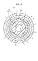
- FIG. 7B is a horizontal cross-sectional view taken along line VIIB-VIIB of FIG. 7A.
- FIG. 7B is a cross-sectional perspective view of the inner cap of FIG. 7A. It is a longitudinal cross-sectional view of the front-end
- FIG. 10 is a cross-sectional view taken along line XX of FIG. 9. It is a cross-sectional perspective view of the inner cap of FIG.
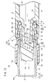
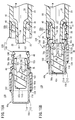
- FIG. 15A is a cross-sectional explanatory view showing a state in which the cap is removed from the cylinder tip portion
- FIG. 15B is a cross-sectional explanatory view showing a state in which the cap is remounted on the cylinder tip portion.
- a prefilled syringe 12A As shown in FIG. 1, a prefilled syringe 12A according to the first embodiment of the present invention has a syringe 17 having a barrel 16 made of a hollow body provided with a barrel tip portion 14 and a barrel tip portion 14 as main components.
- a syringe cap 10A (hereinafter also referred to as "cap 10A") that stops, a piston 18 slidably inserted in the barrel 16, and a liquid chamber defined by the barrel 16 and the piston 18. 20 and the chemical liquid M filled therein.
- the syringe 17 and the cap 10A form a syringe assembly 22A.
- the barrel 16 has a substantially cylindrical shape and has a body portion 24 in which a base end opening portion 23 is formed at the base end, a barrel tip portion 14 (see FIG. 2) provided at the tip of the barrel portion 24, and a barrel tip portion 14 of the barrel tip portion 14.
- the lock adapter 26 is provided on the outside, and the flange 28 is formed so as to project radially outward from the base end of the body portion 24.
- the body portion 24, the barrel tip portion 14, the lock adapter 26, and the flange 28 are integrally formed.
- a piston 18 is inserted into the barrel 16 via a base end opening 23.
- the base end side of the barrel 16 is liquid-tightly sealed by the piston 18, and the chemical liquid M is sealed in the barrel 16.
- the piston 18 is a gasket made of an elastic material such as rubber.
- the outer periphery of the piston 18 is in liquid-tight contact with the inner peripheral surface of the barrel 16 and is slidably arranged in the barrel 16.
- the tip of the pusher 30 is connected to the piston 18. When the user presses the pusher 30 in the tip direction, the piston 18 slides in the barrel 16 in the tip direction.
- the pusher 30 may be connected to the piston 18 when the drug solution M is administered to the patient.
- the barrel tip portion 14 has a diameter reduced from the tip portion of the body portion 24 with respect to the body portion 24 and extends in the tip direction.
- the cylinder tip portion 14 has a tapered outer peripheral surface 32 whose outer diameter decreases toward the tip end direction. That is, the outer peripheral surface 32 of the barrel tip portion 14 forms a luer taper.
- the cylinder tip portion 14 has a liquid passage 34 that communicates with the liquid chamber 20 in the barrel 16 and penetrates in the axial direction. The tip of the liquid passage 34 forms a tip opening 36 of the cylinder tip 14.
- a needle unit (not shown) can be attached to and detached from the barrel tip 14 with the cap 10A removed from the barrel tip 14.
- the needle unit includes a needle body having a needle tip, and a needle hub fixed to a base end portion of the needle body and having a protrusion protruding outward.
- the barrel tip portion 14 can be taper-fitted to the inner peripheral portion of the needle hub.
- the lock adapter 26 of the illustrated example is formed in a substantially hollow circular shape that extends from the tip of the body portion 24 in the tip direction and surrounds the barrel tip portion 14.
- the above-mentioned cylinder tip portion 14 projects in the distal direction from the lock adapter 26, and an annular recess 38 that is recessed in the proximal direction is formed between the lock adapter 26 and the cylinder tip portion 14.
- a female screw portion 40 is formed on the inner peripheral surface of the lock adapter 26.
- the female screw portion 40 is detachably engaged with a male screw portion 46 of the cap 10A, which will be described later. When the cap 10A is detached from the barrel 16, the female screw portion 40 can engage with the protrusion provided on the needle hub of the needle unit described above.
- the lock adapter 26 of the illustrated example is provided as a part of the barrel 16 at the distal end of the body portion 24 by integral molding, but may be provided at the proximal end of the barrel tip portion 14 by integral molding. Good.
- the lock adapter 26 may be a member that is configured as a separate component from the body portion 24 and the barrel tip portion 14 and is fixed to the barrel 16 or the barrel tip portion 14.
- constituent material of the barrel 16 examples include polypropylene, polyethylene, polystyrene, polyamide, polycarbonate, polyvinyl chloride, poly- (4-methylpentene-1), acrylic resin, acrylonitrile-butadiene-styrene copolymer, polyethylene terephthalate and the like. And various resins such as polyester and cyclic polyolefin.
- the cap 10A is detachably attached to the cylinder tip portion 14 and seals the tip end opening portion 36 of the cylinder tip portion 14.
- the illustrated cap 10 ⁇ / b> A is configured to be attachable to and detachable from the barrel tip 14.
- the cap 10 ⁇ / b> A includes an inner cap 42 that seals the tip opening 36, and a hollow cylindrical outer cap 44 that supports the inner cap 42.
- the inner cap 42 is made of an elastic material. In a state in which the cap 10A is attached to the barrel tip portion 14 before use (hereinafter, also referred to as “attached state”), the inner cap 42 is liquid-tightly adhered to the barrel tip portion 14, whereby the chemical liquid is external to the cap 10A. M does not leak out. That is, the inner cap 42 liquid-tightly seals the front end opening 36 of the barrel tip 14 when the cap 10A is mounted.
- Examples of the elastic material forming the inner cap 42 include various rubber materials such as natural rubber, butyl rubber, isoprene rubber, butadiene rubber, styrene-butadiene rubber, and silicone rubber, and polyurethane-based, polyester-based, polyamide-based, olefin-based materials. , Various styrene-based thermoplastic elastomers, or a mixture thereof.
- the outer cap 44 is fixed to the outer circumference of the inner cap 42.
- a male screw portion 46 that is releasably screwed to the female screw portion 40 of the lock adapter 26 is formed on the outer peripheral portion of the base end of the outer cap 44.
- a stopper 48 that projects radially outward is provided on the outer peripheral portion of the outer cap 44 on the tip side of the male screw portion 46.
- the inner cap 42 has a base portion 50 located on the tip side of the cylinder tip portion 14 in the mounted state, and a cylindrical wall portion 52 extending from the base portion 50 in the proximal direction.
- the base portion 50 and the tubular wall portion 52 form a recess 54 that is recessed in the front end direction.
- the base portion 50 constitutes the tip side portion of the inner cap 42.
- annular mounting groove 56 that is recessed radially inward is provided on the outer peripheral portion of the base portion 50, and an annular projection 58 provided on the inner peripheral portion of the outer cap 44 is mounted on the mounting groove. 56 is engaged. As a result, the relative movement of the inner cap 42 and the outer cap 44 in the axial direction is prevented.
- the base end surface 60 of the base portion 50 (the bottom portion of the recessed portion 54) makes one round contact with the tip end surface 35 of the barrel tip portion 14, and is slightly crushed by the tip end surface 35 in the tip end direction.
- the tubular wall portion 52 is formed in a hollow cylindrical shape. In the mounted state of the cap 10A, the tubular wall portion 52 surrounds the tubular tip portion 14.
- the cylindrical wall portion 52 includes an inner peripheral surface 62 that surrounds the outer peripheral surface 32 of the cylinder tip portion 14, and an outer peripheral surface 66 that faces the inner peripheral surface 64 of the outer cap 44.
- the inner peripheral surface 62 of the cylindrical wall portion 52 is formed in a taper shape whose inner diameter expands toward the base end direction.
- the inner peripheral surface 62 of the tubular wall portion 52 has a distal end contact portion 68 disposed at the distal end portion of the tubular wall portion 52, a proximal end contact portion 70 disposed at the proximal end portion of the tubular wall portion 52, It has a non-adhesive portion 72 arranged between the distal end adhesive portion 68 and the proximal end adhesive portion 70.
- the distal end close contact portion 68 is in liquid tight contact with the distal end outer peripheral surface 32a of the cylinder tip portion 14 once, and the proximal end close contact portion 70 is in liquid tight contact with the proximal end outer peripheral surface 32b of the cylinder tip portion 14 once.
- the non-contact portion 72 is separated from the outer peripheral surface 32 of the cylinder tip portion 14. That is, in the mounted state of the cap 10A, a gap S1 is formed between the non-adhesive portion 72 and the outer peripheral surface 32 of the barrel tip portion 14 so as to communicate with the tubular wall portion 52 in the circumferential direction (FIG. 4 and FIG. 4). 5).
- each of the distal end close contact part 68 and the proximal end close contact part 70 extends one round in the circumferential direction of the tubular wall part 52 and expands in a tapered shape toward the proximal end direction.
- the non-contact portion 72 is formed by an annular groove 74 provided in the inner peripheral surface 62 of the cylindrical wall portion 52 in the circumferential direction. That is, the non-contact portion 72 extends once along the circumferential direction of the tubular wall portion 52.
- the depth dimension of the annular groove 74 can be arbitrarily set as long as the gap S1 can be formed between the non-adhered portion 72 and the outer peripheral surface 32 of the barrel tip portion 14 in the mounted state of the cap 10A (FIG. 4 and FIG. 4). 5).
- the non-adhesion portion 72 includes an intermediate portion 73a, a distal end side taper portion 73b connecting the intermediate portion 73a and the distal end adhesion portion 68 to each other, and a proximal end side taper portion 73c connecting the intermediate portion 73a and the proximal end adhesion portion 70 to each other.
- the intermediate portion 73a is enlarged in diameter toward the base end direction at the same taper angle as the tip close contact portion 68 and the base close contact portion 70.
- the tip side taper portion 73b has a diameter that increases toward the base end at a taper angle larger than that of the tip contact portion 68.
- the base end side taper portion 73c is reduced in diameter in the base end direction.
- the length L1 (the length along the axial direction of the tubular wall portion 52) of the non-adhesive portion 72 is greater than the length L2 (the length along the axial direction of the tubular wall portion 52) of the proximal end adhesive portion 70. Is also substantially the same as the length L3 of the tip contact portion 68 (the length along the axial direction of the tubular wall portion 52).
- the length L1 of the non-adhesive portion 72, the length L2 of the proximal end adhering portion 70, and the length L3 of the distal end adhering portion 68 can be set arbitrarily.
- the length L2 of the proximal end contact portion 70 is shorter, the negative pressure in the recess 54 of the tubular wall portion 52 can be released more quickly when the cap 10A is removed from the barrel 16.
- the outer peripheral surface 66 of the tubular wall portion 52 is arranged at a position corresponding to the non-contact portion 72 in the axial direction of the tubular wall portion 52, and is separated from the inner peripheral surface 64 of the outer cap 44. It has the separated part 76. That is, the separating portion 76 is located radially outward of the cylindrical wall portion 52 with respect to the non-contact portion 72.
- the spacing portion 76 is configured to form a gap S ⁇ b> 2 between the spacing portion 76 and the inner peripheral surface 64 of the outer cap 44. The spacing portion 76 is formed once along the circumferential direction of the tubular wall portion 52.
- the outer peripheral surface 66 of the cylindrical wall portion 52 is provided with a protruding portion 78 protruding outward in the radial direction.
- the protrusion 78 is arranged at a position that coincides with the tip contact portion 68 in the axial direction of the tubular wall portion 52. That is, the protrusion 78 is located radially outward of the cylindrical wall 52 with respect to the tip contact portion 68.
- the protrusion 78 extends once along the circumferential direction of the tubular wall 52.
- the protrusion 78 is in close contact with the inner peripheral surface 64 of the outer cap 44 once.
- the protrusion 78 is compressed and deformed in the radial direction of the tubular wall portion 52 by being sandwiched between the tip outer peripheral surface 32a of the cylinder tip portion 14 and the inner peripheral surface 64 of the outer cap 44.
- the tip contact portion 68 strongly adheres to the tip outer peripheral surface 32a of the cylinder tip portion 14.
- the opening operation of the cap 10A of the prefilled syringe 12A will be described below.
- the initial state the state in which the cap 10A is attached
- the distal end close contact portion 68 of the inner cap 42 tightly adheres to the distal end outer peripheral surface 32a of the cylinder tip portion 14 in a liquid-tight manner
- the proximal end close contact portion 70 forms the cylinder tip.
- the non-contact portion 72 of the inner cap 42 is not in contact with the outer peripheral surface 32 of the barrel tip portion 14.
- the user When opening the cap 10A of the prefilled syringe 12A, the user picks the outer peripheral surface of the outer cap 44 with fingers to loosen the screwing (tightening) of the male screw portion 46 of the outer cap 44 to the female screw portion 40 of the barrel 16. Rotate to.
- the cap 10A is displaced in the distal direction with respect to the barrel 16, and the distal end surface 35 of the barrel tip portion 14 is separated from the proximal end surface 60 of the base portion 50.
- the base end close contact portion 70 is separated from the base end outer peripheral surface 32b of the cylinder tip portion 14, and the gap S1 between the non-contact portion 72 and the outer peripheral surface 32 of the cylinder tip portion 14 communicates with the outside.
- the tip contact portion 68 is in contact with the tip outer peripheral surface 32a of the cylinder tip portion 14.
- the tip-adhered portion 68 separates from the tip outer peripheral surface 32 a of the barrel tip portion 14, and inside the recess 54 of the tubular wall portion 52. Is released to the atmosphere (negative pressure in the concave portion 54 of the tubular wall portion 52 is released). As a result, the cap 10A is opened with respect to the barrel 16.
- the proximal end adhered portion 70 is in a state of adhering to the tip outer peripheral surface 32a of the cylinder tip portion 14, and the inside of the recess 54 of the cylindrical wall portion 52 is open to the atmosphere. It does not have to be.
- the cap 10A is further displaced in the distal end direction from the state shown in FIG. 6B, and the proximal end contact portion 70 is separated from the distal end of the cylinder tip portion 14, so that the negative pressure in the concave portion 54 of the cylindrical wall portion 52 is increased. Is released, and the cap 10A is opened with respect to the barrel 16.
- the syringe cap 10A, the syringe assembly 22A, and the prefilled syringe 12A according to the present embodiment have the following effects.
- the inner peripheral surface 62 of the tubular wall portion 52 has a distal end contact portion 68 disposed at the distal end portion of the tubular wall portion 52 and a base disposed at the proximal end portion of the tubular wall portion 52. It has an end contact portion 70 and a non-contact portion 72 disposed between the tip end contact portion 68 and the base end contact portion 70.
- the outer peripheral surface 66 of the tubular wall portion 52 is arranged at a position corresponding to the non-contact portion 72 in the axial direction of the tubular wall portion 52, and has a spacing portion 76 spaced from the inner circumferential surface 64 of the outer cap 44. ing.
- the tip tight contact portion 68 tightly makes a round liquid tight fit to the tip outer peripheral surface 32a of the barrel tip portion 14, and the base end close contact portion 70 is the base end outer circumference of the barrel tip portion 14.
- the non-contact portion 72 is in close contact with the surface 32b, the non-contact portion 72 is separated from the outer peripheral surface 32 of the cylinder tip portion 14, and the separation portion 76 forms a gap S2 between the separation portion 76 and the inner peripheral surface 64 of the outer cap 44.
- the non-adhesive portion 72 of the barrel wall portion 52 separates from the outer peripheral surface 32 of the barrel tip portion 14, and thus the barrel wall portion 52.
- the contact area of the inner peripheral surface 62 with the outer peripheral surface 32 of the cylinder tip portion 14 can be made relatively small. Thereby, the adhesion strength of the inner peripheral surface 62 of the cylindrical wall portion 52 to the outer peripheral surface 32 of the cylinder tip portion 14 can be reduced, and the syringe cap 10A can be easily opened.
- the spacing portion 76 and the inner peripheral surface 64 of the outer cap 44 which are arranged at the positions corresponding to the non-adhesive portion 72 in the axial direction of the tubular wall portion 52, are provided.
- a gap S2 is formed between them. Therefore, it is possible to effectively prevent the cylindrical wall portion 52 from being pushed inward in the radial direction by the outer cap 44 and the non-contact portion 72 coming into contact with the outer peripheral surface 32 of the cylinder tip portion 14.
- the non-contact portion 72 is formed around the tubular wall portion 52 in the circumferential direction. With such a configuration, it is possible to effectively reduce the sticking strength of the inner peripheral surface 62 of the cylindrical wall portion 52 to the outer peripheral surface 32 of the cylinder tip portion 14.
- the separating portion 76 is formed once along the circumferential direction of the tubular wall portion 52. With such a configuration, it is possible to further effectively prevent the cylindrical wall portion 52 from being pushed radially inward by the outer cap 44 and the non-adhesive portion 72 contacting the outer peripheral surface 32 of the cylinder tip portion 14. be able to.
- the syringe assembly 22A includes the above-described syringe cap 10A and the syringe 17 including the barrel 16 having the barrel tip portion 14 at the tip thereof, and the syringe cap 10A is attached to the barrel tip portion 14 of the barrel 16. .. With such a configuration, it is possible to obtain the syringe assembly 22A having the above-described effect.
- the prefilled syringe 12A includes the above-described syringe cap 10A, a syringe 17 having a barrel 16 having a barrel tip portion 14 at its tip, a piston 18 slidably inserted into the barrel 16, a barrel 16 and a piston 18. And a chemical liquid M filled in the liquid chamber 20 defined by. With such a configuration, it is possible to obtain the prefilled syringe 12A having the above-described effect.
- the prefilled syringe 12B includes a syringe 17, a syringe cap 10B (hereinafter, also referred to as “cap 10B”), a piston 18, and a drug solution M.
- the syringe 17 and the cap 10B form a syringe assembly 22B.
- the cap 10B has an inner cap 42a and an outer cap 44.
- the inner cap 42a includes a base portion 50 and a cylindrical wall portion 52a having an inner peripheral surface 62a and an outer peripheral surface 66.
- the inner peripheral surface 62a of the cylindrical wall portion 52a has a front end contact portion 68, a base end contact portion 70, and a non-contact portion 72a (see FIG. 8).
- the non-contact portion 72a has a plurality of (two in the illustrated example) groove portions 80 arranged at intervals along the circumferential direction of the tubular wall portion 52a.
- the groove portion 80 extends in a rectangular shape in the axial direction of the tubular wall portion 52a.
- the tubular wall portion 52a includes a plurality of ribs (two in the illustrated example) protruding from the inner peripheral surface 62a of the tubular wall portion 52a between two groove portions 80 adjacent to each other in the circumferential direction of the tubular wall portion 52a. 82. Thereby, the strength of the portion of the cylindrical wall portion 52a where the groove portion 80 is located can be increased by the ribs 82.
- Each rib 82 extends in the axial direction of the tubular wall portion 52a so as to connect the distal end contact portion 68 and the proximal end contact portion 70 to each other.
- the rib 82 is provided so that the protruding end surface (inner peripheral surface) thereof is flush with the distal end contact portion 68 and the proximal end contact portion 70. In the mounted state of the cap 10B, each rib 82 is in contact with the outer peripheral surface 32 of the barrel tip portion 14 (see FIG. 7B).
- the non-contact portion 72a has a plurality of groove portions 80 arranged at intervals along the circumferential direction of the tubular wall portion 52a, and the tubular wall portion 52a is adjacent to the plurality of groove portions 80.
- a plurality of ribs 82 projecting from the inner peripheral surface 62a of the tubular wall portion 52a are provided between the two groove portions 80.
- the number, depth, shape, size, etc. of the groove 80 and the rib 82 can be set arbitrarily.
- the prefilled syringe 12C includes a syringe 17, a syringe cap 10C (hereinafter, also referred to as “cap 10C”), a piston 18, and a drug solution M.
- the syringe 17 and the cap 10C form a syringe assembly 22C.
- the cap 10C has an inner cap 42b and an outer cap 44. 9 to 11, the inner cap 42b includes a base portion 50 and a cylindrical wall portion 52b having an inner peripheral surface 62b and an outer peripheral surface 66.
- the inner peripheral surface 62b of the cylindrical wall portion 52b has a distal end contact portion 68, a proximal end contact portion 70a, and a non-contact portion 72.
- the tubular wall portion 52b has a plurality of (four in the illustrated example) slits 90 (vertical grooves) that cut out the proximal end contact portion 70a along the axial direction of the tubular wall portion 52b. Each slit 90 extends from the tip end of the base end contact portion 70a to the base end.
- the plurality of slits 90 are arranged at intervals along the circumferential direction of the tubular wall portion 52b.
- the slit 90 is formed so that the depth dimension decreases toward the base end direction.
- Each slit 90 has a bottom surface 92 in the radial direction of the tubular wall portion 52b, and two side surfaces 93 continuous with the bottom surface 92.
- the two side surfaces 93 are located on both sides of the bottom wall 92 in the circumferential direction of the cylindrical wall portion 52b.
- the bottom surface 92 is connected to the proximal end contact portion 70a via the side surface 93.
- the bottom surface 92 is located radially outward of the cylindrical wall portion 52b with respect to the base end contact portion 70a and the side surface 93.
- the bottom surface 92 forming the slit 90 extends substantially parallel to the axial direction of the tubular wall portion 52b (see FIG. 9).
- the base end portion of the bottom surface 92 of the slit 90 is in close contact with the base end outer peripheral surface 32b of the barrel tip portion 14 when the cap 10C is attached. That is, in the mounted state of the cap 10C, the inner peripheral surface 62b of the cylindrical wall portion 52b is in close contact with the base end outer peripheral surface 32b of the cylinder tip portion 14 at the base end portion of the cylindrical wall portion 52b. As a result, the base end portion of the tubular wall portion 52b is liquid-tightly sealed, so that the sterility of the base end outer peripheral surface 32b of the barrel tip portion 14 can be effectively maintained.
- the slit 90 communicates the gap S1 formed between the non-adhesive portion 72 and the outer peripheral surface 32 of the cylinder tip portion 14 with the outside.
- the tubular wall portion 52b has a plurality of slits 90 that cut out the proximal end contact portion 70a along the axial direction of the tubular wall portion 52b, and when the cap 10C is removed from the tubular tip portion 14, slits are formed. 90 connects the space S1 formed between the non-contact portion 72 and the outer peripheral surface 32 of the cylinder tip portion 14 to the outside.
- a plurality of slits 90 are arranged along the circumferential direction of the tubular wall portion 52b.
- At least one slit 90 has a bottom surface 92 in the radial direction of the tubular wall portion 52b, and when the cap 10C is attached to the barrel tip portion 14, the bottom surface 92 forming each slit 90 is a base end of the barrel tip portion 14. It adheres to the outer peripheral surface 32b. With such a configuration, the sterility of the base end outer peripheral surface 32b of the cylinder tip portion 14 can be more reliably maintained, and when the cap 10C is removed from the cylinder tip portion 14, the negative pressure in the recess 54 of the cylindrical wall portion 52b is reduced. Can be quickly released.
- the number, shape, size, etc. of the slits 90 can be set arbitrarily. That is, the number of slits 90 may be one, two, three, or five or more. That is, at least one slit 90 may be provided.
- the slit 90 does not have to be connected to the non-contact portion 72. In this case, since the base end contact portion 70a is located between the slit 90 and the non-contact portion 72, the sterility of the base end portion of the tubular wall portion 52b can be more reliably maintained.
- the respective slits 90 may be set to have the same depth over the entire length of the tubular wall portion 52b along the axial direction. In this case, when the cap 10C is removed from the cylinder tip portion 14, the gap S1 formed between the non-contact portion 72 and the outer peripheral surface 32 of the cylinder tip portion 14 can be more reliably communicated with the outside.
- the non-adhesive portion 72a described in the second embodiment may be provided instead of the non-adhesive portion 72.
- the groove portion 80 and the slit 90 are provided so that the positions of the cylindrical wall portion 52b in the circumferential direction coincide with each other.
- the prefilled syringe 12D includes a syringe 17, a syringe cap 10D (hereinafter, also referred to as “cap 10D”), a piston 18, and a drug solution M.
- the syringe 17 and the cap 10D form a syringe assembly 22D.
- the cap 10D has an inner cap 42c and an outer cap 44a.
- the inner cap 42c includes a base portion 50a and a tubular wall portion 52c having an inner peripheral surface 62c and an outer peripheral surface 66a.
- the base portion 50a is a columnar portion that extends in the axial direction of the inner cap 42c.
- the inner peripheral surface 62c of the cylindrical wall portion 52c has a distal end contact portion 68, a proximal end contact portion 70b, and a non-contact portion 72.
- the tubular wall portion 52c has a plurality of abutting protrusions 100 that protrude radially inward from the base end portion of the base end contact portion 70b.
- the inner diameter of the contact projection 100 is smaller than the outer diameter of the tip of the barrel tip 14 when the cap 10D is removed from the barrel 16.
- the contact protrusion 100 comes into contact with the base end outer peripheral surface 32b of the barrel tip 14. That is, in the mounted state of the cap 10D, the contact convex portion 100 is pressed outward by the cylinder tip portion 14 in the radial direction of the cylindrical wall portion 52c and is compressed and deformed.
- the outer peripheral surface 66a of the cylindrical wall portion 52c is provided with a protruding portion 78a protruding outward in the radial direction.
- the protrusion 78a is arranged at a position that coincides with the proximal end contact portion 70b in the axial direction of the tubular wall portion 52c.
- the protrusion 78a extends once along the circumferential direction of the tubular wall 52c.
- the protrusion 78a is in close contact with an inner peripheral surface 106 of a cap cover 102, which will be described later, that forms the outer cap 44a.
- the protrusion 78a is compressed and deformed in the radial direction of the cylindrical wall 52c by being sandwiched between the base end outer peripheral surface 32b of the cylinder tip 14 and the cap cover 102. To do. As a result, the base end close contact portion 70b strongly adheres to the base end outer peripheral surface 32b of the barrel tip portion 14.
- the outer peripheral surface 66a of the tubular wall portion 52c is arranged at a position that coincides with the non-adhesive portion 72 in the axial direction of the tubular wall portion 52c, and has a spacing portion 76 that is spaced from the inner circumferential surface 106 of the cap cover 102. A gap S2 is formed between the spacing portion 76 and the inner peripheral surface 106 of the cap cover 102.
- the outer cap 44a has a cap cover 102 and a tip cover member 104.
- the cap cover 102 has a cylindrical shape, and is made of a resin material having no transparency (substantially opaque resin material). However, the cap cover 102 may be made of a transparent material.
- a male screw portion 46 and a stopper 48 are provided on the outer peripheral portion of the cap cover 102.
- the inner peripheral surface 106 of the cap cover 102 is provided with a plurality of engaging claws 107 and a first locking convex portion 108.
- the plurality of engaging claws 107 are for pressing the inner cap 42c in the distal end direction with respect to the barrel tip portion 14 when the cap 10D is removed from the barrel 16, and are arranged in the radial direction from the base end portion of the cap cover 102. It projects inward.
- the projecting end of each engagement claw 107 is located radially inward of the tubular wall portion 52c with respect to the outer peripheral surface 66a of the tubular wall portion 52c.
- the first locking protrusion 108 projects radially inward from the axially intermediate portion of the cap cover 102.
- the tip cover member 104 has a substantially U-shaped vertical cross section, and covers the inner cap 42c so that a user who operates the cap 10D together with the cap cover 102 cannot touch the inner cap 42c. That is, the tip cover member 104 has a contact blocking function.
- the tip cover member 104 also has a function as a detachment prevention portion that prevents the inner cap 42c from detaching from the tip opening 110 of the cap cover 102.
- the distal end cover member 104 has an annular portion 112 in which the proximal end portion is fitted to the distal end portion of the cap cover 102 so as to project from the distal end opening portion 110 of the cap cover 102 toward the distal end side. And a tip wall 114 provided at the tip of the annular portion 112.
- the annular portion 112 includes an annular peripheral wall portion 116 on the front end side and a cylindrical engagement extension portion 118 extending from the annular peripheral wall portion 116 in the proximal direction.
- the inner diameter of the annular portion 112 is constant from the tip to the base end, and is larger than the outer diameter of the base portion 50a of the inner cap 42c.
- a second locking protrusion 120, an annular recess 122, and a positioning protrusion 124 are provided on the outer peripheral portion of the engaging extension 118.
- the second locking projection 120 contacts the first locking projection 108 of the cap cover 102 to regulate the displacement of the tip cover member 104 in the distal direction with respect to the cap cover 102.
- the first locking protrusion 108 is fitted in the recess 122.
- the positioning protrusion 124 extends in an annular shape and comes into contact with or approaches the tip end surface of the cap cover 102.
- the tip cover member 104 is integrally molded of a transparent resin material.
- the transparency of the tip cover member 104 is set higher than that of the cap cover 102. Accordingly, the user can visually recognize the inside of the tip cover member 104 from the outside of the cap 10D more clearly than the inside of the cap cover 102.
- the tip cover member 104 is colorless, but it may be colored.
- the inner cap 42c in the mounted state of the cap 10D, is located at the first position where the base 50a is closer to the base end side than the tip opening 110 of the cap cover 102. Specifically, the tip of the inner cap 42 c is located in the proximal direction from the tip opening 110 of the cap cover 102 and within the engagement extension 118 of the tip cover member 104. As a result, the outer peripheral portion of the base portion 50a, which is the visual recognition portion, is hidden by the substantially opaque cap cover 102 and cannot be visually recognized from the outside.
- the cap cover 102 is pulled out from the barrel 16 in a state where the male screw portion 46 and the female screw portion 40 are unscrewed. Then, as shown in FIG. 15A, the plurality of engaging claws 107 come into contact with the base end surface of the inner cap 42c. Then, the inner cap 42c is pushed in the front end direction by the plurality of engaging claws 107, and the tubular wall portion 52c is separated from the tubular tip portion 14. As a result, the cap 10D is opened.
- the tip end portion of the tube tip portion 14 is inserted into the cap cover 102 through the opening on the base end side of the cap cover 102. Then, as shown in FIG. 15B, the tip end portion of the barrel tip portion 14 comes into contact with the contact convex portion 100 of the inner cap 42c.
- the contact projection 100 of the inner cap 42c and the tip end of the barrel tip 14 contact each other, so that the inner cap 42c in the first position moves the barrel tip 42c.
- the base portion 50a is pushed by the portion 14 and displaced in the distal direction with respect to the cap cover 102, and the base portion 50a projects from the distal end opening portion 110 of the cap cover 102 toward the distal end side.
- the opened cap 10D is recapped (reattached) to the barrel tip portion 14.
- the inner cap 42c is located at the second position where the base portion 50a is received in the receiving space S3 formed by the annular peripheral wall portion 116 and the tip wall 114. Therefore, the outer peripheral portion of the base portion 50a, which is the visible portion, can be visually recognized from the outside through the transparent tip cover member 104. This allows the user to easily determine whether or not the cap 10D has been recapped.
- the non-contact portion 72a may be provided instead of the non-contact portion 72, or the slit 90 described in the third embodiment may be provided. Further, in the syringe cap 10D, the non-adhesive portion 72a and the slit 90 may be combined.
- a plurality of separating portions 76 may be arranged at intervals in the circumferential direction of the tubular wall portion 52.
- the portions of the tubular wall portion 52 between the spacing portions 76 adjacent to each other in the circumferential direction may be in contact with the inner peripheral surface 64 of the outer cap 44 in the mounted state of the cap 10A. That is, the outer peripheral surface 66 of the tubular wall portion 52 is arranged at a position that coincides with the non-contact portion 72 in the axial direction of the tubular wall portion 52, and is separated from the inner peripheral surface 64 of the outer cap 44 by at least one space. It may have the portion 76.
- the syringe cap, syringe assembly, and prefilled syringe according to the present invention are not limited to the above-described embodiments, and can of course have various configurations without departing from the gist of the present invention.
Landscapes
- Health & Medical Sciences (AREA)
- Vascular Medicine (AREA)
- Engineering & Computer Science (AREA)
- Anesthesiology (AREA)
- Biomedical Technology (AREA)
- Heart & Thoracic Surgery (AREA)
- Hematology (AREA)
- Life Sciences & Earth Sciences (AREA)
- Animal Behavior & Ethology (AREA)
- General Health & Medical Sciences (AREA)
- Public Health (AREA)
- Veterinary Medicine (AREA)
- Infusion, Injection, And Reservoir Apparatuses (AREA)
Abstract
プレフィルドシリンジ(12A)を形成するシリンジ組立体(22A)は、内側キャップ(42)と外側キャップ(44)とを含むシリンジ用キャップ(10A)を備える。シリンジ用キャップ(10A)が筒先部(14)に装着された時に、先端密着部(68)は、筒先部(14)の先端外周面(32a)に一周液密に密着し、基端密着部(70)は、筒先部(14)の基端外周面(32b)に密着し、非密着部(72)は、筒先部(14)の外周面(32)から離間し、且つ、離間部(76)は、離間部(76)と外側キャップ(44)の内周面(64)との間に隙間(S2)を形成するように構成されている。
Description
本発明は、先端に筒先部を有するバレルを備えたシリンジの前記筒先部に離脱可能に装着され、前記筒先部の先端開口部を封止するためのシリンジ用キャップ、シリンジ組立体及びプレフィルドシリンジに関する。
例えば、米国特許第6520935号明細書には、エラストマー材料により構成された内側キャップと、熱可塑性樹脂により構成されて内側キャップの周囲に固定された筒状の外側キャップとを備えたシリンジ用キャップが開示されている。内側キャップは、基部と、基部から基端方向に延出した筒状壁部を有している。このシリンジ用キャップでは、シリンジの筒先部に装着された状態で、筒状壁部の内周面の全体がシリンジの筒先部の外周面に密着するとともに筒状壁部の外周面が外側キャップに密着している。
ところで、シリンジ用キャップを筒先部に装着した状態で、筒状壁部の内周面が筒先部の外周面に貼り付く(スティッキングする)ことがある。
上述したような米国特許第6520935号明細書のような従来技術では、シリンジ用キャップをシリンジの筒先部に装着した状態で、筒状壁部の内周面の筒状部の外周面に対する接触面積が広いため、筒状壁部の内周面の筒状部の外周面に対する貼り付き強度が比較的大きくなる。そのため、シリンジ用キャップの開封が容易でないことがある。
本発明は、このような課題を考慮してなされたものであり、筒状壁部の内周面の筒先部の外周面に対する貼り付き強度を低減することができ、容易に開封することができるシリンジ用キャップ、シリンジ組立体及びプレフィルドシリンジを提供することを目的とする。
本発明の第1の態様は、先端に筒先部を有するバレルを備えたシリンジの前記筒先部に離脱可能に装着され、前記筒先部の先端開口部を封止するためのシリンジ用キャップであって、弾性材料により構成され、前記シリンジ用キャップが前記筒先部に装着された時に、前記筒先部の前記先端開口部を液密に封止する内側キャップと、前記内側キャップよりも硬質の材料により構成され、前記内側キャップの周囲に固定された筒状の外側キャップと、を備え、前記内側キャップは、基部と、前記基部から基端方向に延出した筒状壁部と、を有し、前記筒状壁部は、前記筒先部の外周面を囲む内周面と、前記外側キャップの内周面と対向する外周面と、を有し、前記筒状壁部の前記内周面は、前記筒状壁部の先端部に配置された先端密着部と、前記筒状壁部の基端部に配置された基端密着部と、前記先端密着部と前記基端密着部との間に配置された非密着部と、を有し、前記筒状壁部の前記外周面は、前記筒状壁部の軸方向において、前記非密着部と一致する位置に配置され、前記外側キャップの前記内周面から離間した少なくとも1つの離間部を有し、前記シリンジ用キャップが前記筒先部に装着された時に、前記先端密着部は、前記筒先部の先端外周面に一周液密に密着し、前記基端密着部は、前記筒先部の基端外周面に密着し、前記非密着部は、前記筒先部の前記外周面から離間し、且つ、前記少なくとも1つの離間部は、前記離間部と前記外側キャップの前記内周面との間に隙間を形成する、シリンジ用キャップである。
本発明の第2の態様は、上述したシリンジ用キャップと、先端に筒先部を有するバレルを備えたシリンジと、を備え、前記シリンジ用キャップは、前記バレルの前記筒先部に装着されている、シリンジ組立体である。
本発明の第3の態様は、上述したシリンジ用キャップと、先端に筒先部を有するバレルを備えたシリンジと、前記バレル内に摺動可能に挿入されたピストンと、前記バレルと前記ピストンとで画成される液室内に充填された薬液と、を備える、プレフィルドシリンジである。
本発明によれば、シリンジ用キャップが筒先部に装着された時に、筒状壁部の非密着部が筒先部の外周面から離間するため、筒状壁部の内周面の筒先部の外周面に対する接触面積を比較的小さくすることができる。これにより、筒状壁部の内周面の筒先部の外周面に対する貼り付き強度を低減することができ、シリンジ用キャップを容易に開封することができる。また、シリンジ用キャップが筒先部に装着された時に、筒状壁部の軸方向において非密着部と一致する位置に配置された離間部と外側キャップの内周面との間に隙間が形成されている。よって、筒状壁部が外側キャップによって径方向内方に押されて非密着部が筒先部の外周面に接触してしまうことを効果的に抑えることができる。
以下、本発明に係るシリンジ用キャップ、シリンジ組立体及びプレフィルドシリンジについて好適な実施形態を挙げ、添付の図面を参照しながら説明する。プレフィルドシリンジ及びその構成要素に関する以下の説明では、図1の左側を「先端」、右側を「基端」という。
(第1実施形態)
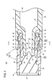
図1に示すように、本発明の第1実施形態に係るプレフィルドシリンジ12Aは、主たる構成要素として、筒先部14が設けられた中空体からなるバレル16を有するシリンジ17と、筒先部14を封止するシリンジ用キャップ10A(以下、「キャップ10A」と呼ぶことがある。)と、バレル16内に摺動可能に挿入されたピストン18と、バレル16とピストン18とで画成される液室20内に充填された薬液Mとを備える。シリンジ17とキャップ10Aとにより、シリンジ組立体22Aが構成されている。
図1に示すように、本発明の第1実施形態に係るプレフィルドシリンジ12Aは、主たる構成要素として、筒先部14が設けられた中空体からなるバレル16を有するシリンジ17と、筒先部14を封止するシリンジ用キャップ10A(以下、「キャップ10A」と呼ぶことがある。)と、バレル16内に摺動可能に挿入されたピストン18と、バレル16とピストン18とで画成される液室20内に充填された薬液Mとを備える。シリンジ17とキャップ10Aとにより、シリンジ組立体22Aが構成されている。
バレル16は、略円筒形状をなすとともに基端に基端開口部23が形成された胴体部24と、胴体部24の先端に設けられた筒先部14(図2参照)と、筒先部14の外側に設けられたロックアダプタ26と、胴体部24の基端から径方向外方に突出形成されたフランジ28とを有する。図示例のバレル16において、胴体部24、筒先部14、ロックアダプタ26及びフランジ28は一体成形されている。バレル16内には、基端開口部23を介してピストン18が挿入されている。ピストン18によってバレル16の基端側が液密に封止され、薬液Mがバレル16内に封入されている。
ピストン18は、例えばゴム材等の弾性材料により構成されたガスケットである。ピストン18は、その外周部がバレル16の内周面に液密に接するとともに、バレル16内に摺動可能に配置されている。ピストン18には、押し子30の先端部が連結されている。ユーザが押し子30を先端方向に押圧することにより、ピストン18がバレル16内を先端方向に摺動する。なお、押し子30は、薬液Mを患者に投与するときにピストン18に連結されてもよい。
図2及び図4に示すように、筒先部14は、胴体部24の先端部から胴体部24に対して縮径して先端方向に延出している。筒先部14は、先端方向に向かうに従って外径が縮小するテーパ状の外周面32を有する。すなわち、筒先部14の外周面32は、ルアーテーパを構成している。図4において、筒先部14は、バレル16内の液室20と連通し且つ軸方向に貫通した液体通路34を有する。液体通路34の先端が、筒先部14の先端開口部36を形成している。
筒先部14からキャップ10Aが外された状態で、筒先部14には、図示しない針ユニットが着脱可能である。針ユニットは、針先を有する針体と、針体の基端部に固定されるとともに外方に突出した突起を有する針ハブとを備える。筒先部14は、針ハブの内周部にテーパ嵌合可能である。プレフィルドシリンジ12Aの使用に際し、キャップ10Aは開栓され(筒先部14及びロックアダプタ26から取り外され)、代わりに針ユニットの針ハブが筒先部14及びロックアダプタ26に接続される。
図2及び図4に示すように、図示例のロックアダプタ26は、胴体部24の先端から先端方向に延出し且つ筒先部14を囲む略中空円状に構成されている。上述した筒先部14は、ロックアダプタ26よりも先端方向に突出しており、ロックアダプタ26と筒先部14との間には、基端方向に凹む環状凹部38が形成されている。ロックアダプタ26の内周面には雌ネジ部40が形成されている。雌ネジ部40は、キャップ10Aの後述する雄ネジ部46と離脱可能に螺合している。キャップ10Aがバレル16から離脱した状態で、雌ネジ部40は、上述した針ユニットの針ハブに設けられた突起と係合可能である。
なお、本図示例のロックアダプタ26は、バレル16の一部として、胴体部24の先端部に一体成形によって設けられているが、筒先部14の基端部に一体成形によって設けられていてもよい。あるいは、ロックアダプタ26は、胴体部24及び筒先部14とは別部品として構成され、バレル16又は筒先部14に固定された部材であってもよい。
バレル16の構成材料としては、例えば、ポリプロピレン、ポリエチレン、ポリスチレン、ポリアミド、ポリカーボネート、ポリ塩化ビニル、ポリ-(4-メチルペンテン-1)、アクリル樹脂、アクリロニトリル-ブタジエン-スチレン共重合体、ポリエチレンテレフタレート等のポリエステル、環状ポリオレフィンのような各種樹脂が挙げられる。
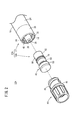
図2~図4に示すように、キャップ10Aは、筒先部14に離脱可能に装着されており、筒先部14の先端開口部36を封止する。図示例のキャップ10Aは、筒先部14に着脱可能に構成されている。キャップ10Aは、先端開口部36を封止する内側キャップ42と、内側キャップ42を支持する中空円筒状の外側キャップ44とを備える。
内側キャップ42は、弾性材料により構成されている。筒先部14にキャップ10Aが装着された使用前の状態(以下、「装着状態」ともいう)では、内側キャップ42が筒先部14に液密に密着しており、これによりキャップ10Aの外部に薬液Mが漏れ出ないようになっている。すなわち、内側キャップ42は、キャップ10Aの装着状態で筒先部14の先端開口部36を液密に封止する。
内側キャップ42を構成する弾性材料としては、例えば、天然ゴム、ブチルゴム、イソプレンゴム、ブタジエンゴム、スチレン-ブタジエンゴム、シリコーンゴムのような各種ゴム材料や、ポリウレタン系、ポリエステル系、ポリアミド系、オレフィン系、スチレン系等の各種熱可塑性エラストマー、あるいはそれらの混合物等が挙げられる。
外側キャップ44は、内側キャップ42の外周に固定されている。外側キャップ44の基端外周部には、ロックアダプタ26の雌ネジ部40に解除可能に螺合する雄ネジ部46が形成されている。外側キャップ44の外周部において雄ネジ部46よりも先端側には、径方向外側に突出するストッパ48が設けられている。
キャップ10Aがしっかりと(完全に)筒先部14及びロックアダプタ26に装着された状態では、外側キャップ44は、ストッパ48の基端面とロックアダプタ26の先端面とが当接する位置までロックアダプタ26に捩じ込まれている。
次に、内側キャップ42の構成について、より詳細に説明する。内側キャップ42は、装着状態で筒先部14よりも先端側に位置する基部50と、基部50から基端方向に延出した筒状壁部52とを有する。基部50と筒状壁部52とにより先端方向に凹む凹部54が形成されている。基部50は、内側キャップ42の先端側部分を構成している。
図3及び図4に示すように、基部50の外周部には径方向内側に凹む環状の装着溝56が設けられており、外側キャップ44の内周部に設けられた環状突起58が装着溝56に係合している。これにより、内側キャップ42と外側キャップ44との軸方向の相対移動が阻止されている。図3において、基部50の基端面60(凹部54の底部)は、筒先部14の先端面35と一周密着し、先端面35によって先端方向に若干だけ押し潰されている。
図4において、筒状壁部52は、中空円筒形状に形成されている。キャップ10Aの装着状態で、筒状壁部52は筒先部14を囲んでいる。筒状壁部52は、筒先部14の外周面32を囲む内周面62と、外側キャップ44の内周面64と対向する外周面66とを含む。
図3において、筒状壁部52の内周面62は、基端方向に向かうに従って内径が拡径するテーパ状に形成されている。筒状壁部52の内周面62は、筒状壁部52の先端部に配置された先端密着部68と、筒状壁部52の基端部に配置された基端密着部70と、先端密着部68と基端密着部70との間に配置された非密着部72とを有する。
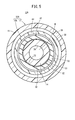
図4に示すキャップ10Aの装着状態で、先端密着部68は筒先部14の先端外周面32aに一周液密に接し、基端密着部70は筒先部14の基端外周面32bに一周液密に接し、非密着部72は筒先部14の外周面32から離間している。すなわち、キャップ10Aの装着状態で、非密着部72と筒先部14の外周面32との間には、筒状壁部52の周方向に一周連通した隙間S1が形成される(図4及び図5参照)。
図3において、先端密着部68及び基端密着部70のそれぞれは、筒状壁部52の周方向に一周延在するとともに基端方向に向かってテーパ状に拡径している。非密着部72は、筒状壁部52の内周面62に周方向に設けられた環状溝74によって形成されている。つまり、非密着部72は、筒状壁部52の周方向に沿って一周延在している。環状溝74の深さ寸法は、キャップ10Aの装着状態で非密着部72と筒先部14の外周面32との間に隙間S1が形成することができれば任意に設定可能である(図4及び図5参照)。
非密着部72は、中間部73aと、中間部73a及び先端密着部68を互いに連結する先端側テーパ部73bと、中間部73a及び基端密着部70を互いに連結する基端側テーパ部73cとを有する。中間部73aは、基端方向に向かって先端密着部68及び基端密着部70と同じテーパ角度で拡径している。先端側テーパ部73bは、基端方向に向かって先端密着部68よりも大きなテーパ角度で拡径している。基端側テーパ部73cは、基端方向に向かって縮径している。
非密着部72の長さL1(筒状壁部52の軸方向に沿った長さ)は、基端密着部70の長さL2(筒状壁部52の軸方向に沿った長さ)よりも長く、先端密着部68の長さL3(筒状壁部52の軸方向に沿った長さ)と略同じである。ただし、非密着部72の長さL1、基端密着部70の長さL2及び先端密着部68の長さL3は、任意に設定することができる。
非密着部72の長さL1が長いほど、筒状壁部52の内周面62の筒先部14の外周面32に対する貼り付き強度を小さくすることができる。基端密着部70の長さL2が長いほど、筒先部14の基端部の無菌性を確実に維持することができる。基端密着部70の長さL2が短いほど、バレル16からキャップ10Aを取り外す際に筒状壁部52の凹部54内の陰圧をより素早く解除することができる。
図3及び図4において、筒状壁部52の外周面66は、筒状壁部52の軸方向において、非密着部72と一致する位置に配置され、外側キャップ44の内周面64から離間した離間部76を有する。つまり、離間部76は、非密着部72に対して筒状壁部52の径方向外方に位置する。キャップ10Aの装着状態で、離間部76は、離間部76と外側キャップ44の内周面64との間に隙間S2を形成するように構成されている。離間部76は、筒状壁部52の周方向に沿って一周形成されている。
筒状壁部52の外周面66には、径方向外方に突出した突起部78が設けられている。突起部78は、筒状壁部52の軸方向において、先端密着部68と一致する位置に配置されている。つまり、突起部78は、先端密着部68に対して筒状壁部52の径方向外方に位置する。突起部78は、筒状壁部52の周方向に沿って一周延在している。突起部78は、外側キャップ44の内周面64に一周密着している。キャップ10Aの装着状態で、突起部78は、筒先部14の先端外周面32aと外側キャップ44の内周面64とに挟まれることで、筒状壁部52の径方向に圧縮変形する。これにより、先端密着部68は、筒先部14の先端外周面32aに強く密着する。
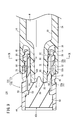
このように構成されるプレフィルドシリンジ12Aのキャップ10Aの開封動作について、以下に説明する。初期状態(キャップ10Aの装着状態)では、図4に示すように、内側キャップ42の先端密着部68が筒先部14の先端外周面32aに一周液密に密着するとともに基端密着部70が筒先部14の基端外周面32bに一周液密に密着している。これにより、筒先部14の外周面32及び先端面35(上述した針ユニットの針ハブが接触する部分)の無菌性が維持される。なお、内側キャップ42の非密着部72は、筒先部14の外周面32に接触していない。
プレフィルドシリンジ12Aのキャップ10Aを開封する場合、ユーザは、外側キャップ44の外周面を手指で摘み、外側キャップ44の雄ネジ部46のバレル16の雌ネジ部40に対する螺合(締め付け)が緩む方向に回転させる。
そうすると、図6Aに示すように、キャップ10Aがバレル16に対して先端方向に変位して筒先部14の先端面35が基部50の基端面60から離間する。また、基端密着部70が筒先部14の基端外周面32bから離間し、非密着部72と筒先部14の外周面32との間の隙間S1が外部に連通する。なお、先端密着部68は、筒先部14の先端外周面32aに接触している。
そして、図6Bに示すように、非密着部72が筒先部14の先端に達した時に、先端密着部68が筒先部14の先端外周面32aから離間し、筒状壁部52の凹部54内が大気開放される(筒状壁部52の凹部54内の陰圧が解除される)。これにより、キャップ10Aがバレル16に対して開封されるに至る。なお、非密着部72が筒先部14の先端に達した時に、基端密着部70が筒先部14の先端外周面32aに密着した状態であり、筒状壁部52の凹部54内が大気開放されていなくてもよい。この場合、キャップ10Aが、図6Bに示す状態からさらに先端方向に変位して、基端密着部70が筒先部14の先端から離間することにより、筒状壁部52の凹部54内の陰圧が解除され、キャップ10Aがバレル16に対して開封されるに至る。
この場合、本実施形態に係るシリンジ用キャップ10A、シリンジ組立体22A及びプレフィルドシリンジ12Aは、以下の効果を奏する。
シリンジ用キャップ10Aにおいて、筒状壁部52の内周面62は、筒状壁部52の先端部に配置された先端密着部68と、筒状壁部52の基端部に配置された基端密着部70と、先端密着部68と基端密着部70との間に配置された非密着部72と、を有している。筒状壁部52の外周面66は、筒状壁部52の軸方向において、非密着部72と一致する位置に配置され、外側キャップ44の内周面64から離間した離間部76を有している。
シリンジ用キャップ10Aが筒先部14に装着された時に、先端密着部68は、筒先部14の先端外周面32aに一周液密に密着し、基端密着部70は、筒先部14の基端外周面32bに密着し、非密着部72は、筒先部14の外周面32から離間し、且つ、離間部76は、離間部76と外側キャップ44の内周面64との間に隙間S2を形成する。
このような構成によれば、シリンジ用キャップ10Aが筒先部14に装着された時に、筒状壁部52の非密着部72が筒先部14の外周面32から離間するため、筒状壁部52の内周面62の筒先部14の外周面32に対する接触面積を比較的小さくすることができる。これにより、筒状壁部52の内周面62の筒先部14の外周面32に対する貼り付き強度を低減することができ、シリンジ用キャップ10Aを容易に開封することができる。また、シリンジ用キャップ10Aが筒先部14に装着された時に、筒状壁部52の軸方向において非密着部72と一致する位置に配置された離間部76と外側キャップ44の内周面64との間に隙間S2が形成されている。よって、筒状壁部52が外側キャップ44によって径方向内方に押されて非密着部72が筒先部14の外周面32に接触してしまうことを効果的に抑えることができる。
非密着部72は、筒状壁部52の周方向に沿って一周形成されている。このような構成によれば、筒状壁部52の内周面62の筒先部14の外周面32に対する貼り付き強度を効果的に低減することができる。
離間部76は、筒状壁部52の周方向に沿って一周形成されている。このような構成によれば、筒状壁部52が外側キャップ44によって径方向内方に押されて非密着部72が筒先部14の外周面32に接触してしまうことを一層効果的に抑えることができる。
シリンジ組立体22Aは、上述したシリンジ用キャップ10Aと、先端に筒先部14を有するバレル16を備えたシリンジ17と、を備え、シリンジ用キャップ10Aは、バレル16の筒先部14に装着されている。このような構成によれば、上述した効果を奏するシリンジ組立体22Aを得ることができる。
プレフィルドシリンジ12Aは、上述したシリンジ用キャップ10Aと、先端に筒先部14を有するバレル16を備えたシリンジ17と、バレル16内に摺動可能に挿入されたピストン18と、バレル16とピストン18とで画成される液室20内に充填された薬液Mと、を備える。このような構成によれば、上述した効果を奏するプレフィルドシリンジ12Aを得ることができる。
(第2実施形態)
次に、本発明の第2実施形態に係るシリンジ用キャップ10B、シリンジ組立体22B及びプレフィルドシリンジ12Bについて説明する。なお、第2実施形態に係るプレフィルドシリンジ12Bにおいて、上述した第1実施形態に係るプレフィルドシリンジ12Aと同一の構成要素には同一の参照符号を付し、詳細な説明は省略する。また、本実施形態において、第1実施形態に係るプレフィルドシリンジ12Aと同様の構成については同様の作用効果を奏する。後述する第3実施形態及び第4実施形態についても同様である。
次に、本発明の第2実施形態に係るシリンジ用キャップ10B、シリンジ組立体22B及びプレフィルドシリンジ12Bについて説明する。なお、第2実施形態に係るプレフィルドシリンジ12Bにおいて、上述した第1実施形態に係るプレフィルドシリンジ12Aと同一の構成要素には同一の参照符号を付し、詳細な説明は省略する。また、本実施形態において、第1実施形態に係るプレフィルドシリンジ12Aと同様の構成については同様の作用効果を奏する。後述する第3実施形態及び第4実施形態についても同様である。
図7A及び図7Bに示すように、プレフィルドシリンジ12Bは、シリンジ17、シリンジ用キャップ10B(以下、「キャップ10B」と呼ぶことがある。)、ピストン18及び薬液Mを備える。シリンジ17とキャップ10Bとによりシリンジ組立体22Bが構成される。
キャップ10Bは、内側キャップ42a及び外側キャップ44を有する。図7A~図8に示すように、内側キャップ42aは、基部50と、内周面62a及び外周面66を有する筒状壁部52aとを含む。筒状壁部52aの内周面62aは、先端密着部68、基端密着部70及び非密着部72aを有する(図8参照)。非密着部72aは、筒状壁部52aの周方向に沿って間隔を空けて配置された複数(図示例では2つ)の溝部80を有する。溝部80は、筒状壁部52aの軸方向に矩形状に延在している。
筒状壁部52aは、筒状壁部52aの周方向に互いに隣接する2つの溝部80の間に、筒状壁部52aの内周面62aから突出した複数(図示例では2つ)のリブ82を有する。これにより、筒状壁部52aのうち溝部80が位置する部分の強度をリブ82によって高めることができる。各リブ82は、先端密着部68と基端密着部70とを互いに繋ぐように筒状壁部52aの軸方向に延在している。換言すれば、リブ82は、その突出端面(内周面)が、先端密着部68及び基端密着部70に面一になるように設けられている。キャップ10Bの装着状態で、各リブ82は、筒先部14の外周面32に当接している(図7B参照)。
本実施形態によれば、第1実施形態で説明したシリンジ用キャップ10Aと同様の効果を奏する。
本実施形態において、非密着部72aは、筒状壁部52aの周方向に沿って間隔を空けて配置された複数の溝部80を有し、筒状壁部52aは、複数の溝部80の隣接する2つの溝部80の間に、筒状壁部52aの内周面62aから突出した複数のリブ82を有している。シリンジ用キャップ10Bが筒先部14に装着された時に、複数のリブ82は、筒先部14の外周面32に当接する。
このような構成によれば、リブ82があるため、シリンジ用キャップ10Bの装着状態で非密着部72aが筒先部14の外周面32に密着することをより確実に抑えることができる。
溝部80及びリブ82の数、深さ、形状、大きさ等は、任意に設定することができる。
(第3実施形態)
次に、本発明の第3実施形態に係るシリンジ用キャップ10C、シリンジ組立体22C及びプレフィルドシリンジ12Cについて説明する。
次に、本発明の第3実施形態に係るシリンジ用キャップ10C、シリンジ組立体22C及びプレフィルドシリンジ12Cについて説明する。
図9及び図10に示すように、プレフィルドシリンジ12Cは、シリンジ17、シリンジ用キャップ10C(以下、「キャップ10C」と呼ぶことがある。)、ピストン18及び薬液Mを備える。シリンジ17とキャップ10Cとによりシリンジ組立体22Cが構成される。
キャップ10Cは、内側キャップ42b及び外側キャップ44を有する。図9~図11において、内側キャップ42bは、基部50と、内周面62b及び外周面66を有する筒状壁部52bを含む。筒状壁部52bの内周面62bは、先端密着部68、基端密着部70a及び非密着部72を有する。筒状壁部52bは、筒状壁部52bの軸方向に沿って基端密着部70aを切り欠く複数(図示例では4つ)のスリット90(縦溝)を有する。各スリット90は、基端密着部70aの先端から基端まで延在している。複数のスリット90は、筒状壁部52bの周方向に沿って間隔を空けて配置されている。スリット90は、基端方向に向かって深さ寸法が小さくなるように形成されている。各スリット90は、筒状壁部52bの径方向における底面92と、底面92に連なる2つの側面93とを有する。2つの側面93は、底面92における筒状壁部52bの周方向の両側に位置する。底面92は、側面93を介して基端密着部70aに連なる。内側キャップ42bが筒先部14に装着されていない状態で、底面92は、基端密着部70a及び側面93よりも筒状壁部52bの径方向外方に位置している。スリット90を形成する底面92は、筒状壁部52bの軸方向と略平行に延在している(図9参照)。
図9に示すように、キャップ10Cの装着状態で、スリット90の底面92の基端部は、筒先部14の基端外周面32bに密着している。つまり、キャップ10Cの装着状態で、筒状壁部52bの内周面62bは、筒状壁部52bの基端部で筒先部14の基端外周面32bに一周密着している。これにより、筒状壁部52bの基端部が液密に封止されるため、筒先部14の基端外周面32bの無菌性を効果的に維持することができる。キャップ10Cを筒先部14から取り外す時に、スリット90は、非密着部72と筒先部14の外周面32との間に形成される隙間S1と外部とを互いに連通する。
本実施形態によれば、第1実施形態で説明したキャップ10Aと同様の効果を奏する。
本実施形態において、筒状壁部52bは、筒状壁部52bの軸方向に沿って基端密着部70aを切り欠く複数のスリット90を有し、キャップ10Cを筒先部14から取り外す時に、スリット90は、非密着部72と筒先部14の外周面32との間に形成された隙間S1と外部とを連通する。
このような構成によれば、キャップ10Cを筒先部14から取り外す時に、非密着部72と筒先部14の外周面32との隙間S1とスリット90とを介して筒状壁部52bの凹部54内を外部に連通させることができるため、筒状壁部52bの凹部54内の陰圧を素早く解除することができる。よって、バレル16内の薬液Mが筒状壁部52bの凹部54内に陰圧によって引き出されることを防止することができる。
スリット90は、筒状壁部52bの周方向に沿って複数配置されている。このような構成によれば、キャップ10Cを筒先部14から取り外す時に、筒状壁部52bの凹部54内の陰圧を確実且つ素早く解除することができる。
少なくとも1つのスリット90は、筒状壁部52bの径方向における底面92を有し、キャップ10Cが筒先部14に装着された時に、各スリット90を形成する底面92は、筒先部14の基端外周面32bに密着する。このような構成によれば、筒先部14の基端外周面32bの無菌性をより確実に維持できるとともに、キャップ10Cを筒先部14から取り外す時に、筒状壁部52bの凹部54内の陰圧を素早く解除することができる。
スリット90の数、形状、大きさ等は、任意に設定することができる。つまり、スリット90の数は、1つであってもよいし、2つ、3つ又は5つ以上であってもよい。すなわち、スリット90は、少なくとも1つあればよい。スリット90は、非密着部72に繋がっていなくてもよい。この場合、スリット90と非密着部72との間に基端密着部70aが位置することになるため、筒状壁部52bの基端部の無菌性を一層確実に保つことができる。
各スリット90は、筒状壁部52bの軸方向に沿った全長に亘って同じ深さに設定されていてもよい。この場合、キャップ10Cを筒先部14から取り外す時に、非密着部72と筒先部14の外周面32との間に形成される隙間S1と外部とを一層確実に連通させることができる。
シリンジ用キャップ10Cでは、非密着部72に代えて第2実施形態で説明した非密着部72aが設けられていてもよい。この場合、溝部80とスリット90とは、筒状壁部52bの周方向の位置が一致するように設けるのが好ましい。
(第4実施形態)
次に、本発明の第4実施形態に係るシリンジ用キャップ10D、シリンジ組立体22D及びプレフィルドシリンジ12Dについて説明する。
次に、本発明の第4実施形態に係るシリンジ用キャップ10D、シリンジ組立体22D及びプレフィルドシリンジ12Dについて説明する。
図12~図15Bに示すように、プレフィルドシリンジ12Dは、シリンジ17、シリンジ用キャップ10D(以下、「キャップ10D」と呼ぶことがある。)、ピストン18及び薬液Mを備える。シリンジ17とキャップ10Dとによりシリンジ組立体22Dが構成される。
キャップ10Dは、内側キャップ42c及び外側キャップ44aを有する。内側キャップ42cは、基部50aと、内周面62c及び外周面66aを有する筒状壁部52cとを含む。基部50aは、内側キャップ42cの軸方向に延在した円柱部である。
図12及び図14において、筒状壁部52cの内周面62cは、先端密着部68、基端密着部70b及び非密着部72を有する。筒状壁部52cは、基端密着部70bの基端部から径方向内方に突出した複数の当接凸部100を有する。図15Aに示すように、バレル16からキャップ10Dを取り外した状態で、当接凸部100の内径は、筒先部14の先端の外径よりも小さい。図12に示すように、キャップ10Dの装着状態で、当接凸部100は、筒先部14の基端外周面32bに接触する。つまり、キャップ10Dの装着状態で、当接凸部100は、筒先部14によって筒状壁部52cの径方向外方に押され圧縮変形している。
筒状壁部52cの外周面66aには、径方向外方に突出した突起部78aが設けられている。突起部78aは、筒状壁部52cの軸方向において、基端密着部70bと一致する位置に配置されている。突起部78aは、筒状壁部52cの周方向に沿って一周延在している。突起部78aは、外側キャップ44aを形成する後述するキャップカバー102の内周面106に一周密着している。
図12に示すように、キャップ10Dの装着状態で、突起部78aは、筒先部14の基端外周面32bとキャップカバー102とに挟まれることで、筒状壁部52cの径方向に圧縮変形する。これにより、基端密着部70bは、筒先部14の基端外周面32bに強く密着する。筒状壁部52cの外周面66aは、筒状壁部52cの軸方向において、非密着部72と一致する位置に配置され、キャップカバー102の内周面106から離間した離間部76を有する。離間部76とキャップカバー102の内周面106との間には、隙間S2が形成されている。
外側キャップ44aは、キャップカバー102及び先端カバー部材104を有する。キャップカバー102は、円筒状に構成されており、透明性を有しない樹脂材料(実質的に不透明な樹脂材料)により構成されている。ただし、キャップカバー102は、透明性を有する材料により構成されていてもよい。
キャップカバー102の外周部には、雄ネジ部46とストッパ48とが設けられている。キャップカバー102の内周面106には、複数の係合爪107と、第1係止凸部108が設けられている。複数の係合爪107は、キャップ10Dをバレル16から取り外す際に、内側キャップ42cを筒先部14に対して先端方向に押圧するためのものであって、キャップカバー102の基端部から径方向内方に突出している。キャップ10Dの装着状態で、各係合爪107の突出端は、筒状壁部52cの外周面66aよりも筒状壁部52cの径方向内方に位置する。第1係止凸部108は、キャップカバー102の軸方向の中間部から径方向内方に向かって突出している。
先端カバー部材104は、縦断面が略U字状に形成されており、キャップカバー102とともにキャップ10Dを操作するユーザが内側キャップ42cに触れることができないように、内側キャップ42cを覆うものである。すなわち、先端カバー部材104は、接触阻止機能を有する。先端カバー部材104は、内側キャップ42cがキャップカバー102の先端開口部110から離脱することを阻止する離脱阻止部としての機能も有する。
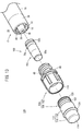
図12及び図13に示すように、先端カバー部材104は、キャップカバー102の先端開口部110から先端側に突出するようにキャップカバー102の先端部に基端部が嵌合された環状部112と、環状部112の先端部に設けられた先端壁114とを有する。
環状部112は、先端側の環状周壁部116と、環状周壁部116から基端方向へ延びる筒状の係合延出部118とからなる。環状部112の内径は、その先端から基端まで一定であり、内側キャップ42cの基部50aの外径よりも大きい。
係合延出部118の外周部には、第2係止凸部120と、環状の凹部122と、位置決め突起124が設けられている。第2係止凸部120は、キャップカバー102の第1係止凸部108に接触することにより先端カバー部材104のキャップカバー102に対する先端方向の変位を規制する。凹部122には、第1係止凸部108が嵌合する。位置決め突起124は、円環状に延在しており、キャップカバー102の先端面に接触又は近接する。
先端カバー部材104は、透明性を有する樹脂材料で一体的に成形されている。キャップカバー102が透明性を有する樹脂材料で構成されている場合、先端カバー部材104の透明度は、キャップカバー102の透明度よりも高く設定される。これにより、ユーザは、キャップ10Dの外側から先端カバー部材104の内部をキャップカバー102の内部よりも鮮明に視認することができる。本実施形態では、先端カバー部材104は無色であるが、着色されていても構わない。
このようなプレフィルドシリンジ12Dでは、キャップ10Dの装着状態で、内側キャップ42cは、基部50aがキャップカバー102の先端開口部110よりも基端側にある第1の位置に位置している。具体的には、内側キャップ42cの先端は、キャップカバー102の先端開口部110よりも基端方向且つ先端カバー部材104の係合延出部118内に位置している。これにより、視認部である基部50aの外周部は、実質的に不透明なキャップカバー102に隠され、外部から視認できない。
キャップ10Dを筒先部14から開封する場合、雄ネジ部46と雌ネジ部40との螺合を解除した状態でキャップカバー102をバレル16から引き抜く。そうすると、図15Aに示すように、複数の係合爪107が内側キャップ42cの基端面に接触する。そして、内側キャップ42cが複数の係合爪107によって先端方向に押され、筒状壁部52cが筒先部14から離脱される。これにより、キャップ10Dが開封されるに至る。
開封済みのキャップ10Dを筒先部14にリキャップする場合、筒先部14の先端部をキャップカバー102の基端側の開口部からキャップカバー102内に挿入する。そうすると、図15Bに示すように、筒先部14の先端部が内側キャップ42cの当接凸部100に接触する。
続いて、キャップカバー102とバレル16とを互いに近接させると、内側キャップ42cの当接凸部100と筒先部14の先端部との当接により、第1の位置にある内側キャップ42cは、筒先部14に押されてキャップカバー102に対して先端方向に変位し、基部50aがキャップカバー102の先端開口部110から先端側に突出する。
そして、雄ネジ部46を雌ネジ部40に螺合させることにより、開封済みのキャップ10Dが筒先部14に対してリキャップ(再装着)される。このとき、内側キャップ42cは、基部50aが環状周壁部116と先端壁114とから形成される受容空間S3に受容された第2の位置に位置する。このため、視認部である基部50aの外周部は、透明な先端カバー部材104を介して、外部から視認可能となる。これにより、ユーザは、キャップ10Dがリキャップされたものか否かを容易に判断することができる。
本実施形態によれば、第1実施形態に係るキャップ10Aと同様の効果を奏する。
シリンジ用キャップ10Dでは、非密着部72に代えて第2実施形態で説明した非密着部72aを設けてもよいし、第3実施形態で説明したスリット90を設けてもよい。また、シリンジ用キャップ10Dでは、非密着部72aとスリット90とを組み合わせてもよい。
シリンジ用キャップ10Aにおいて、例えば、離間部76は、筒状壁部52の周方向に間隔を空けて複数配置されていてもよい。この場合、筒状壁部52の周方向に互いに隣り合う離間部76の間の部分は、キャップ10Aの装着状態で外側キャップ44の内周面64に接触していてもよい。すなわち、筒状壁部52の外周面66は、筒状壁部52の軸方向において、非密着部72と一致する位置に配置され、外側キャップ44の内周面64から離間した少なくとも1つの離間部76を有していればよい。このような場合であっても、非密着部72が外側キャップ44によって径方向内方に押されて筒先部14の外周面32に接触することを抑えることができる。シリンジ用キャップ10B~10Dの離間部76についても同様である。
本発明に係るシリンジ用キャップ、シリンジ組立体及びプレフィルドシリンジは、上述の実施形態に限らず、本発明の要旨を逸脱することなく、種々の構成を採り得ることはもちろんである。
Claims (9)
- 先端に筒先部を有するバレルを備えたシリンジの前記筒先部に離脱可能に装着され、前記筒先部の先端開口部を封止するためのシリンジ用キャップであって、
弾性材料により構成され、前記シリンジ用キャップが前記筒先部に装着された時に、前記筒先部の前記先端開口部を液密に封止する内側キャップと、
前記内側キャップよりも硬質の材料により構成され、前記内側キャップの周囲に固定された筒状の外側キャップと、を備え、
前記内側キャップは、基部と、前記基部から基端方向に延出した筒状壁部と、を有し、
前記筒状壁部は、前記筒先部の外周面を囲む内周面と、前記外側キャップの内周面と対向する外周面と、を有し、
前記筒状壁部の前記内周面は、
前記筒状壁部の先端部に配置された先端密着部と、
前記筒状壁部の基端部に配置された基端密着部と、
前記先端密着部と前記基端密着部との間に配置された非密着部と、を有し、
前記筒状壁部の前記外周面は、前記筒状壁部の軸方向において、前記非密着部と一致する位置に配置され、前記外側キャップの前記内周面から離間した少なくとも1つの離間部を有し、
前記シリンジ用キャップが前記筒先部に装着された時に、前記先端密着部は、前記筒先部の先端外周面に一周液密に密着し、前記基端密着部は、前記筒先部の基端外周面に密着し、前記非密着部は、前記筒先部の前記外周面から離間し、且つ、前記少なくとも1つの離間部は、前記離間部と前記外側キャップの前記内周面との間に隙間を形成する、シリンジ用キャップ。 - 請求項1記載のシリンジ用キャップであって、
前記非密着部は、前記筒状壁部の周方向に沿って一周形成されている、シリンジ用キャップ。 - 請求項1又は2に記載のシリンジ用キャップであって、
前記少なくとも1つの離間部は、前記筒状壁部の周方向に沿って一周形成されている、シリンジ用キャップ。 - 請求項1又は3に記載のシリンジ用キャップであって、
前記非密着部は、前記筒状壁部の周方向に沿って間隔を空けて配置された複数の溝部を有し、
前記筒状壁部は、前記複数の溝部の隣接する2つの溝部の間に、前記筒状壁部の内周面から突出した複数のリブを有し、
前記シリンジ用キャップが前記筒先部に装着された時に、前記複数のリブは、前記筒先部の外周面に当接する、シリンジ用キャップ。 - 請求項1~4のいずれか1項に記載のシリンジ用キャップであって、
前記筒状壁部は、前記筒状壁部の前記軸方向に沿って前記基端密着部を切り欠く少なくとも1つのスリットを有し、
前記内側キャップを前記筒先部から取り外す時に、前記スリットは、前記非密着部と前記筒先部の外周面との間に形成される前記隙間と外部とを連通する、シリンジ用キャップ。 - 請求項5記載のシリンジ用キャップであって、
前記少なくとも1つのスリットは、前記筒状壁部の周方向に沿って複数配置されている、シリンジ用キャップ。 - 請求項5又は6記載のシリンジ用キャップであって、
前記少なくとも1つのスリットは、前記筒状壁部の径方向における底面を有し、
前記シリンジ用キャップが前記筒先部に装着された時に、前記少なくとも1つのスリットの前記底面は、前記筒先部の前記基端外周面に密着する、シリンジ用キャップ。 - 請求項1~7のいずれか1項に記載のシリンジ用キャップと、
先端に筒先部を有するバレルを備えたシリンジと、を備え、
前記シリンジ用キャップは、前記バレルの前記筒先部に装着されている、シリンジ組立体。 - 請求項1~7のいずれかに記載のシリンジ用キャップと、
先端に筒先部を有するバレルを備えたシリンジと、
前記バレル内に摺動可能に挿入されたピストンと、
前記バレルと前記ピストンとで画成される液室内に充填された薬液と、を備える、プレフィルドシリンジ。
Priority Applications (1)
| Application Number | Priority Date | Filing Date | Title |
|---|---|---|---|
| JP2020556145A JP7322061B2 (ja) | 2018-11-15 | 2019-11-13 | シリンジ用キャップ、シリンジ組立体及びプレフィルドシリンジ |
Applications Claiming Priority (2)
| Application Number | Priority Date | Filing Date | Title |
|---|---|---|---|
| JP2018-214673 | 2018-11-15 | ||
| JP2018214673 | 2018-11-15 |
Publications (1)
| Publication Number | Publication Date |
|---|---|
| WO2020100953A1 true WO2020100953A1 (ja) | 2020-05-22 |
Family
ID=70730724
Family Applications (1)
| Application Number | Title | Priority Date | Filing Date |
|---|---|---|---|
| PCT/JP2019/044587 Ceased WO2020100953A1 (ja) | 2018-11-15 | 2019-11-13 | シリンジ用キャップ、シリンジ組立体及びプレフィルドシリンジ |
Country Status (2)
| Country | Link |
|---|---|
| JP (1) | JP7322061B2 (ja) |
| WO (1) | WO2020100953A1 (ja) |
Citations (3)
| Publication number | Priority date | Publication date | Assignee | Title |
|---|---|---|---|---|
| JPH08215307A (ja) * | 1994-12-12 | 1996-08-27 | Becton Dickinson & Co | 注射器先端キャップ |
| WO2017179313A1 (ja) * | 2016-04-15 | 2017-10-19 | テルモ株式会社 | シリンジ用バレル及びその製造方法並びにプレフィルドシリンジ |
| WO2018061948A1 (ja) * | 2016-09-30 | 2018-04-05 | テルモ株式会社 | キャップ、シリンジ組立体及びプレフィルドシリンジ |
-
2019
- 2019-11-13 JP JP2020556145A patent/JP7322061B2/ja active Active
- 2019-11-13 WO PCT/JP2019/044587 patent/WO2020100953A1/ja not_active Ceased
Patent Citations (3)
| Publication number | Priority date | Publication date | Assignee | Title |
|---|---|---|---|---|
| JPH08215307A (ja) * | 1994-12-12 | 1996-08-27 | Becton Dickinson & Co | 注射器先端キャップ |
| WO2017179313A1 (ja) * | 2016-04-15 | 2017-10-19 | テルモ株式会社 | シリンジ用バレル及びその製造方法並びにプレフィルドシリンジ |
| WO2018061948A1 (ja) * | 2016-09-30 | 2018-04-05 | テルモ株式会社 | キャップ、シリンジ組立体及びプレフィルドシリンジ |
Also Published As
| Publication number | Publication date |
|---|---|
| JP7322061B2 (ja) | 2023-08-07 |
| JPWO2020100953A1 (ja) | 2021-09-30 |
Similar Documents
| Publication | Publication Date | Title |
|---|---|---|
| US11273264B2 (en) | Cap, syringe assembly, and prefilled syringe | |
| JP6873173B2 (ja) | 薬物送達デバイス用のアダプタおよび前記アダプタをそこに装着するための方法 | |
| JP7241166B2 (ja) | シリンジ用キャップ、シリンジ組立体及びプレフィルドシリンジ | |
| JP2017196499A (ja) | シリンジ | |
| WO2011108574A1 (ja) | シリンジ | |
| US10238817B2 (en) | Prefilled syringe | |
| JPWO2011125475A1 (ja) | シリンジ | |
| WO2013047042A1 (ja) | シリンジ | |
| US11660402B2 (en) | Syringe and prefilled syringe | |
| AU2023229546B2 (en) | Syringe cap, syringe assembly, and pre-filled syringe | |
| JP7322061B2 (ja) | シリンジ用キャップ、シリンジ組立体及びプレフィルドシリンジ | |
| WO2011122351A1 (ja) | シリンジセット | |
| EP3603603A1 (en) | Female syringe and syringe kit | |
| US12397121B2 (en) | Syringe cap, syringe assembly, and prefilled syringe | |
| JP4173302B2 (ja) | 医療用針 | |
| JP7133504B2 (ja) | 封止組立体及びシリンジ | |
| JPWO2017170634A1 (ja) | シール部材、シリンジ組立体及びプレフィルドシリンジ |
Legal Events
| Date | Code | Title | Description |
|---|---|---|---|
| 121 | Ep: the epo has been informed by wipo that ep was designated in this application |
Ref document number: 19884737 Country of ref document: EP Kind code of ref document: A1 |
|
| ENP | Entry into the national phase |
Ref document number: 2020556145 Country of ref document: JP Kind code of ref document: A |
|
| NENP | Non-entry into the national phase |
Ref country code: DE |
|
| 122 | Ep: pct application non-entry in european phase |
Ref document number: 19884737 Country of ref document: EP Kind code of ref document: A1 |