WO2020100746A1 - 粉体燃料供給装置、ガス化炉設備およびガス化複合発電設備ならびに粉体燃料供給装置の制御方法 - Google Patents
粉体燃料供給装置、ガス化炉設備およびガス化複合発電設備ならびに粉体燃料供給装置の制御方法 Download PDFInfo
- Publication number
- WO2020100746A1 WO2020100746A1 PCT/JP2019/043921 JP2019043921W WO2020100746A1 WO 2020100746 A1 WO2020100746 A1 WO 2020100746A1 JP 2019043921 W JP2019043921 W JP 2019043921W WO 2020100746 A1 WO2020100746 A1 WO 2020100746A1
- Authority
- WO
- WIPO (PCT)
- Prior art keywords
- gas
- powder fuel
- mixing chamber
- supply device
- inert gas
- Prior art date
- Legal status (The legal status is an assumption and is not a legal conclusion. Google has not performed a legal analysis and makes no representation as to the accuracy of the status listed.)
- Ceased
Links
Images


Classifications
-
- C—CHEMISTRY; METALLURGY
- C10—PETROLEUM, GAS OR COKE INDUSTRIES; TECHNICAL GASES CONTAINING CARBON MONOXIDE; FUELS; LUBRICANTS; PEAT
- C10J—PRODUCTION OF PRODUCER GAS, WATER-GAS, SYNTHESIS GAS FROM SOLID CARBONACEOUS MATERIAL, OR MIXTURES CONTAINING THESE GASES; CARBURETTING AIR OR OTHER GASES
- C10J3/00—Production of combustible gases containing carbon monoxide from solid carbonaceous fuels
- C10J3/46—Gasification of granular or pulverulent flues in suspension
- C10J3/48—Apparatus; Plants
- C10J3/50—Fuel charging devices
- C10J3/506—Fuel charging devices for entrained flow gasifiers
-
- C—CHEMISTRY; METALLURGY
- C10—PETROLEUM, GAS OR COKE INDUSTRIES; TECHNICAL GASES CONTAINING CARBON MONOXIDE; FUELS; LUBRICANTS; PEAT
- C10J—PRODUCTION OF PRODUCER GAS, WATER-GAS, SYNTHESIS GAS FROM SOLID CARBONACEOUS MATERIAL, OR MIXTURES CONTAINING THESE GASES; CARBURETTING AIR OR OTHER GASES
- C10J3/00—Production of combustible gases containing carbon monoxide from solid carbonaceous fuels
- C10J3/46—Gasification of granular or pulverulent flues in suspension
- C10J3/48—Apparatus; Plants
- C10J3/50—Fuel charging devices
-
- C—CHEMISTRY; METALLURGY
- C10—PETROLEUM, GAS OR COKE INDUSTRIES; TECHNICAL GASES CONTAINING CARBON MONOXIDE; FUELS; LUBRICANTS; PEAT
- C10J—PRODUCTION OF PRODUCER GAS, WATER-GAS, SYNTHESIS GAS FROM SOLID CARBONACEOUS MATERIAL, OR MIXTURES CONTAINING THESE GASES; CARBURETTING AIR OR OTHER GASES
- C10J3/00—Production of combustible gases containing carbon monoxide from solid carbonaceous fuels
- C10J3/72—Other features
- C10J3/723—Controlling or regulating the gasification process
-
- F—MECHANICAL ENGINEERING; LIGHTING; HEATING; WEAPONS; BLASTING
- F02—COMBUSTION ENGINES; HOT-GAS OR COMBUSTION-PRODUCT ENGINE PLANTS
- F02C—GAS-TURBINE PLANTS; AIR INTAKES FOR JET-PROPULSION PLANTS; CONTROLLING FUEL SUPPLY IN AIR-BREATHING JET-PROPULSION PLANTS
- F02C3/00—Gas-turbine plants characterised by the use of combustion products as the working fluid
- F02C3/20—Gas-turbine plants characterised by the use of combustion products as the working fluid using a special fuel, oxidant, or dilution fluid to generate the combustion products
- F02C3/26—Gas-turbine plants characterised by the use of combustion products as the working fluid using a special fuel, oxidant, or dilution fluid to generate the combustion products the fuel or oxidant being solid or pulverulent, e.g. in slurry or suspension
-
- F—MECHANICAL ENGINEERING; LIGHTING; HEATING; WEAPONS; BLASTING
- F02—COMBUSTION ENGINES; HOT-GAS OR COMBUSTION-PRODUCT ENGINE PLANTS
- F02C—GAS-TURBINE PLANTS; AIR INTAKES FOR JET-PROPULSION PLANTS; CONTROLLING FUEL SUPPLY IN AIR-BREATHING JET-PROPULSION PLANTS
- F02C3/00—Gas-turbine plants characterised by the use of combustion products as the working fluid
- F02C3/20—Gas-turbine plants characterised by the use of combustion products as the working fluid using a special fuel, oxidant, or dilution fluid to generate the combustion products
- F02C3/26—Gas-turbine plants characterised by the use of combustion products as the working fluid using a special fuel, oxidant, or dilution fluid to generate the combustion products the fuel or oxidant being solid or pulverulent, e.g. in slurry or suspension
- F02C3/28—Gas-turbine plants characterised by the use of combustion products as the working fluid using a special fuel, oxidant, or dilution fluid to generate the combustion products the fuel or oxidant being solid or pulverulent, e.g. in slurry or suspension using a separate gas producer for gasifying the fuel before combustion
-
- F—MECHANICAL ENGINEERING; LIGHTING; HEATING; WEAPONS; BLASTING
- F02—COMBUSTION ENGINES; HOT-GAS OR COMBUSTION-PRODUCT ENGINE PLANTS
- F02C—GAS-TURBINE PLANTS; AIR INTAKES FOR JET-PROPULSION PLANTS; CONTROLLING FUEL SUPPLY IN AIR-BREATHING JET-PROPULSION PLANTS
- F02C6/00—Plural gas-turbine plants; Combinations of gas-turbine plants with other apparatus; Adaptations of gas-turbine plants for special use
- F02C6/18—Plural gas-turbine plants; Combinations of gas-turbine plants with other apparatus; Adaptations of gas-turbine plants for special use using the waste heat of gas-turbine plants outside the plants themselves, e.g. gas-turbine power heat plants
-
- F—MECHANICAL ENGINEERING; LIGHTING; HEATING; WEAPONS; BLASTING
- F23—COMBUSTION APPARATUS; COMBUSTION PROCESSES
- F23B—METHODS OR APPARATUS FOR COMBUSTION USING ONLY SOLID FUEL
- F23B90/00—Combustion methods not related to a particular type of apparatus
- F23B90/04—Combustion methods not related to a particular type of apparatus including secondary combustion
- F23B90/06—Combustion methods not related to a particular type of apparatus including secondary combustion the primary combustion being a gasification or pyrolysis in a reductive atmosphere
-
- F—MECHANICAL ENGINEERING; LIGHTING; HEATING; WEAPONS; BLASTING
- F23—COMBUSTION APPARATUS; COMBUSTION PROCESSES
- F23K—FEEDING FUEL TO COMBUSTION APPARATUS
- F23K3/00—Feeding or distributing of lump or pulverulent fuel to combustion apparatus
- F23K3/02—Pneumatic feeding arrangements, i.e. by air blast
-
- C—CHEMISTRY; METALLURGY
- C10—PETROLEUM, GAS OR COKE INDUSTRIES; TECHNICAL GASES CONTAINING CARBON MONOXIDE; FUELS; LUBRICANTS; PEAT
- C10J—PRODUCTION OF PRODUCER GAS, WATER-GAS, SYNTHESIS GAS FROM SOLID CARBONACEOUS MATERIAL, OR MIXTURES CONTAINING THESE GASES; CARBURETTING AIR OR OTHER GASES
- C10J2300/00—Details of gasification processes
- C10J2300/16—Integration of gasification processes with another plant or parts within the plant
- C10J2300/164—Integration of gasification processes with another plant or parts within the plant with conversion of synthesis gas
- C10J2300/1643—Conversion of synthesis gas to energy
- C10J2300/165—Conversion of synthesis gas to energy integrated with a gas turbine or gas motor
-
- C—CHEMISTRY; METALLURGY
- C10—PETROLEUM, GAS OR COKE INDUSTRIES; TECHNICAL GASES CONTAINING CARBON MONOXIDE; FUELS; LUBRICANTS; PEAT
- C10J—PRODUCTION OF PRODUCER GAS, WATER-GAS, SYNTHESIS GAS FROM SOLID CARBONACEOUS MATERIAL, OR MIXTURES CONTAINING THESE GASES; CARBURETTING AIR OR OTHER GASES
- C10J2300/00—Details of gasification processes
- C10J2300/16—Integration of gasification processes with another plant or parts within the plant
- C10J2300/164—Integration of gasification processes with another plant or parts within the plant with conversion of synthesis gas
- C10J2300/1643—Conversion of synthesis gas to energy
- C10J2300/1653—Conversion of synthesis gas to energy integrated in a gasification combined cycle [IGCC]
-
- C—CHEMISTRY; METALLURGY
- C10—PETROLEUM, GAS OR COKE INDUSTRIES; TECHNICAL GASES CONTAINING CARBON MONOXIDE; FUELS; LUBRICANTS; PEAT
- C10J—PRODUCTION OF PRODUCER GAS, WATER-GAS, SYNTHESIS GAS FROM SOLID CARBONACEOUS MATERIAL, OR MIXTURES CONTAINING THESE GASES; CARBURETTING AIR OR OTHER GASES
- C10J2300/00—Details of gasification processes
- C10J2300/16—Integration of gasification processes with another plant or parts within the plant
- C10J2300/1671—Integration of gasification processes with another plant or parts within the plant with the production of electricity
- C10J2300/1675—Integration of gasification processes with another plant or parts within the plant with the production of electricity making use of a steam turbine
-
- F—MECHANICAL ENGINEERING; LIGHTING; HEATING; WEAPONS; BLASTING
- F05—INDEXING SCHEMES RELATING TO ENGINES OR PUMPS IN VARIOUS SUBCLASSES OF CLASSES F01-F04
- F05D—INDEXING SCHEME FOR ASPECTS RELATING TO NON-POSITIVE-DISPLACEMENT MACHINES OR ENGINES, GAS-TURBINES OR JET-PROPULSION PLANTS
- F05D2220/00—Application
- F05D2220/30—Application in turbines
- F05D2220/32—Application in turbines in gas turbines
-
- F—MECHANICAL ENGINEERING; LIGHTING; HEATING; WEAPONS; BLASTING
- F23—COMBUSTION APPARATUS; COMBUSTION PROCESSES
- F23L—SUPPLYING AIR OR NON-COMBUSTIBLE LIQUIDS OR GASES TO COMBUSTION APPARATUS IN GENERAL ; VALVES OR DAMPERS SPECIALLY ADAPTED FOR CONTROLLING AIR SUPPLY OR DRAUGHT IN COMBUSTION APPARATUS; INDUCING DRAUGHT IN COMBUSTION APPARATUS; TOPS FOR CHIMNEYS OR VENTILATING SHAFTS; TERMINALS FOR FLUES
- F23L2900/00—Special arrangements for supplying or treating air or oxidant for combustion; Injecting inert gas, water or steam into the combustion chamber
- F23L2900/07002—Injecting inert gas, other than steam or evaporated water, into the combustion chambers
-
- Y—GENERAL TAGGING OF NEW TECHNOLOGICAL DEVELOPMENTS; GENERAL TAGGING OF CROSS-SECTIONAL TECHNOLOGIES SPANNING OVER SEVERAL SECTIONS OF THE IPC; TECHNICAL SUBJECTS COVERED BY FORMER USPC CROSS-REFERENCE ART COLLECTIONS [XRACs] AND DIGESTS
- Y02—TECHNOLOGIES OR APPLICATIONS FOR MITIGATION OR ADAPTATION AGAINST CLIMATE CHANGE
- Y02E—REDUCTION OF GREENHOUSE GAS [GHG] EMISSIONS, RELATED TO ENERGY GENERATION, TRANSMISSION OR DISTRIBUTION
- Y02E20/00—Combustion technologies with mitigation potential
- Y02E20/16—Combined cycle power plant [CCPP], or combined cycle gas turbine [CCGT]
- Y02E20/18—Integrated gasification combined cycle [IGCC], e.g. combined with carbon capture and storage [CCS]
-
- Y—GENERAL TAGGING OF NEW TECHNOLOGICAL DEVELOPMENTS; GENERAL TAGGING OF CROSS-SECTIONAL TECHNOLOGIES SPANNING OVER SEVERAL SECTIONS OF THE IPC; TECHNICAL SUBJECTS COVERED BY FORMER USPC CROSS-REFERENCE ART COLLECTIONS [XRACs] AND DIGESTS
- Y02—TECHNOLOGIES OR APPLICATIONS FOR MITIGATION OR ADAPTATION AGAINST CLIMATE CHANGE
- Y02P—CLIMATE CHANGE MITIGATION TECHNOLOGIES IN THE PRODUCTION OR PROCESSING OF GOODS
- Y02P20/00—Technologies relating to chemical industry
- Y02P20/10—Process efficiency
- Y02P20/129—Energy recovery, e.g. by cogeneration, H2recovery or pressure recovery turbines
Definitions
- the present invention relates to a powder fuel supply device, a gasification furnace facility, a gasification combined cycle power generation facility, and a method for controlling the powder fuel supply device.
- a fuel supply device that supplies powdered fuel such as pulverized coal and char together with nitrogen (inert gas) into a gasification furnace is known.
- powdered fuel such as pulverized coal and char together with nitrogen (inert gas) into a gasification furnace.
- additional supply of diluted nitrogen is performed.
- the supply of the diluted nitrogen from the diluted nitrogen system into the transfer pipe is performed using, for example, a mixing chamber connected to the transfer pipe.
- a filter is installed so that diluted nitrogen can be accelerated and supplied. Condensed water may adhere to the filter due to backflow of a mixed gas of powder fuel and nitrogen from the mixing chamber to the diluted nitrogen system. If water adheres to the filter, a pressure difference may occur between the inside and outside of the filter.
- Patent Document 1 discloses that a backwash gas is passed in the opposite direction in order to remove dust adhering to the surface of the filter.
- Patent Document 1 has a problem that a separate structure for flowing the backwash gas is required, which requires cost and installation place.
- the present invention has been made in view of the above circumstances, and has a simple and inexpensive structure, which is capable of suppressing the backflow of a mixed gas, a powder fuel supply device, a gasification furnace facility, and a gasification composite.
- An object of the present invention is to provide a method for controlling a power generation facility and a powder fuel supply device.
- a powder fuel supply device is a mixture including a gas in which powder fuel and a accompanying inert gas carried along with the powder fuel are mixed and water. Additional inertness to the powder conveying pipe through which the gas is conveyed and to the mixing chamber connected to the powder conveying pipe and arranged in the middle of the powder conveying pipe when the flow rate of the mixed gas is less than a predetermined threshold value.
- the additional inert gas supply unit additionally supplies the additional inert gas supply unit, which constantly supplies the mixing chamber with the predetermined flow rate of the additional inert gas. It is possible to prevent the mixed gas from flowing backward from the mixing chamber to the additional inert gas supply unit during the operation.
- the predetermined flow rate of the additional inert gas may be a flow rate that suppresses the backflow of the mixed gas from the mixing chamber to the additional inert gas supply unit.
- the predetermined flow rate of the additional inert gas is a flow rate that reduces the occurrence of the backflow of the mixed gas from the mixing chamber to the additional inert gas supply unit. From this, the flow rate of the inert gas can be minimized. Further, it is possible to prevent the backflow of the mixed gas to the additional inert gas supply unit from occurring.
- the additional inert gas supply unit may be heated by a heat source to a temperature equal to or higher than the saturation temperature of water contained in the mixed gas.
- the additional inert gas supply unit is heated by the heat source to a state at which the temperature of the water contained in the mixed gas is equal to or higher than the saturation temperature. According to this aspect, even when the mixed gas flows backward to the additional inert gas supply unit, the water contained in the mixed gas can be converted into water vapor without dew condensation. Since the water vapor is carried together with the inert gas and the mixed gas, it is possible to suppress the water from staying in the additional inert gas supply unit and the powder carrying pipe.
- the additional inert gas supply unit may include a drain discharge unit that discharges drain.
- the additional inert gas supply unit includes a drain discharge unit that discharges accumulated drain. According to this aspect, even when the mixed gas flows back to the additional inert gas supply unit and the moisture contained in the mixed gas is condensed to become water, the water is not transferred before being transferred to the powder transfer pipe. Can be discharged from the additional inert gas supply section as drain. Since the drain is discharged from the additional inert gas supply unit, it is possible to prevent water from returning to and accumulated in the powder carrying pipe.
- each of the mixing chambers is cylindrical and has a plurality of sintered metal filters made of a porous body having a predetermined thickness, and an annular shape connected and fixed to an outer peripheral portion of the plurality of sintered metal filters.
- An intermediate ring may be provided, and the central axes of the plurality of sintered metal filters and the central axis of the intermediate ring may be provided along a central axis direction of the mixing chamber.
- the mixing chamber has a plurality of cylindrical sintered metal filters each having a predetermined thickness, and an intermediate ring connected and fixed to an outer peripheral portion of each sintered metal filter.
- the center axis of the sintered metal filter and the center axis of the intermediate ring are provided along the center axis direction of the mixing chamber.
- a short cylindrical sintered metal filter can be connected by an intermediate ring to be used as one long cylindrical shape.
- the length of each sintered metal filter supported between the intermediate rings becomes shorter as compared with the case where the mixing chamber is configured by one sintered metal filter.
- both ends of the sintered metal filter are reinforced by the intermediate rings.
- the strength with respect to the pressure in the direction perpendicular to the central axis direction of the sintered metal filter can be increased.
- the mixed gas may flow back to the additional inert gas supply unit to condense moisture and become water, and this water may flow to the powder conveying pipe side and stay there. If this water adheres to the sintered metal filter or passes through the sintered metal filter, the differential pressure will increase. Even if the differential pressure increases due to water, it is possible to minimize the effect of the differential pressure increase on the deformation of the sintered metal filter. Further, even if it is deformed, only the target short sintered metal filter needs to be replaced, so that the cost required for replacement can be reduced.
- a gasification furnace facility is the above-described powder fuel supply device, and a gas for supplying powder fuel from the powder fuel supply device to gasify the powder fuel. And a chemical furnace.
- Gasification combined cycle power generation equipment is rotationally driven by burning at least a part of the above-mentioned gasification furnace equipment and the generated gas generated in the gasification furnace equipment.
- a method of controlling a powder fuel supply device is a gas and water in which powder fuel and a accompanying inert gas that is carried along with the powder fuel are mixed. And a mixing chamber arranged in the middle of the powder conveying pipe connected to the powder conveying pipe when the flow velocity of the mixed gas is less than a predetermined threshold value.
- An additional inert gas supply section for additionally supplying an additional inert gas to the powder fuel supply apparatus, wherein the additional inert gas supply section has a predetermined flow rate to the mixing chamber. The step of constantly supplying the additional inert gas is included.
- the additional inert gas of a predetermined flow rate is constantly supplied from the additional inert gas supply unit to the mixing chamber, the moisture from the mixing chamber to the additional inert gas supply unit is simple and inexpensive. The backflow of the mixed gas containing the gas can be suppressed.
- FIG. 3 is a schematic view of a part of a sintered metal filter of an aspect of the mixing chamber of the powder fuel supply device according to some embodiments.
- FIG. 1 shows a schematic configuration of an integrated coal gasification combined cycle power generation facility to which a gasification furnace facility of one aspect of a powder fuel supply device according to some embodiments of the present disclosure is applied.
- An integrated coal gasification combined cycle (IGCC) 10 uses air as an oxidant mainly, and in a gasification furnace facility 14, an air that produces a combustible gas (produced gas) from fuel. It uses a combustion method.
- the integrated coal gasification combined cycle power generation facility 10 refines the generated gas generated in the gasification furnace facility 14 in the gas purification facility 16 into a fuel gas, and then supplies the gas to the gas turbine 17 for power generation. That is, the integrated coal gasification combined cycle power generation facility 10 is an air combustion type (air blowing) power generation facility.
- the fuel supplied to the gasification furnace facility 14 for example, carbon-containing solid fuel such as coal is used.
- the positional relationship of each component described using the expressions of the upper side and the upper side and the lower side and the lower side respectively indicates the vertically upper side and the vertically lower side.
- a coal gasification combined cycle power generation facility (gasification combined power generation facility) 10 includes a coal feeding facility 11, a gasification furnace facility 14, a char recovery facility 15, a gas refining facility 16, and a gas turbine. 17, a steam turbine 18, a generator 19, and a heat recovery steam generator (HRSG: Heat Recovery Steam Generator) 20.
- gasification combined power generation facility gasification combined power generation facility 10 includes a coal feeding facility 11, a gasification furnace facility 14, a char recovery facility 15, a gas refining facility 16, and a gas turbine. 17, a steam turbine 18, a generator 19, and a heat recovery steam generator (HRSG: Heat Recovery Steam Generator) 20.
- HRSG Heat Recovery Steam Generator
- the coal supply facility 11 is supplied with coal, which is a carbon-containing solid fuel, as raw coal, and pulverizes the coal with a coal mill (not shown) or the like to produce pulverized coal (powder fuel) pulverized into fine particles.
- the pulverized coal produced in the coal feeding facility 11 is pressurized by nitrogen gas (accompanied inert gas) as a carrier inert gas supplied from the air separation facility 42 described later at the outlet of the coal feeding line 11a, and gasified. It is supplied to the furnace equipment 14.
- the inert gas is an inert gas having an oxygen content of about 5% by volume or less. Nitrogen gas, carbon dioxide gas, argon gas and the like are typical examples of inert gas, but they are not necessarily limited to about 5% by volume or less.
- the gasification furnace facility 14 is supplied with the pulverized coal produced in the coal feeding facility 11, and the char (unreacted content of coal and ash: powder fuel) recovered in the char recovery facility 15 is returned and regenerated. It is provided for the purpose of use.
- a compressed air supply line 41 from the gas turbine 17 (compressor 61) is connected to the gasification furnace facility 14. A part of the compressed air compressed by the gas turbine 17 is pressurized to a predetermined pressure by the booster 68 and can be supplied to the gasification furnace facility 14.
- the air separation equipment 42 separates nitrogen and oxygen from air in the atmosphere, and the first nitrogen supply line 43 connects the air separation equipment 42 and the gasification furnace equipment 14.
- a coal supply line 11 a from the coal supply facility 11 is connected to the first nitrogen supply line 43.
- a second nitrogen supply line 45 branched from the first nitrogen supply line 43 is also connected to the gasification furnace facility 14.
- a char return line 46 from the char recovery facility 15 is connected to the second nitrogen supply line 45.
- the air separation equipment 42 is connected to the compressed air supply line 41 by an oxygen supply line 47.
- the nitrogen separated by the air separation facility 42 is used as a carrier gas for coal or char by flowing through the first nitrogen supply line 43 and the second nitrogen supply line 45.
- the oxygen separated by the air separation equipment 42 is used as an oxidant in the gasification furnace equipment 14 by flowing through the oxygen supply line 47 and the compressed air supply line 41.
- the gasifier equipment 14 is equipped with, for example, a two-stage spouted bed type gasifier.
- the gasification furnace facility 14 partially combusts the coal (pulverized coal) and the char supplied inside with an oxidizer (air, oxygen) to gasify and produce product gas.
- the gasification furnace facility 14 is provided with a foreign matter removing facility 48 for removing foreign matter (slag) mixed in the pulverized coal.
- a gas generation line 49 for supplying the generated gas to the char recovery facility 15 is connected to the gasification furnace facility 14 so that the generated gas containing char can be discharged.
- a syngas cooler gas cooler
- the char collection facility 15 includes a dust collection facility 51 and a supply hopper 52.
- the dust collecting equipment 51 is composed of one or a plurality of cyclones or porous filters, and can separate the char contained in the produced gas produced in the gasification furnace equipment 14.
- the produced gas from which the char has been separated is sent to the gas purification facility 16 through the gas discharge line 53.
- the supply hopper 52 stores the char separated from the generated gas in the dust collecting facility 51.
- a bin may be arranged between the dust collecting equipment 51 and the supply hopper 52, and a plurality of supply hoppers 52 may be connected to this bin.
- the char return line 46 from the supply hopper 52 is connected to the second nitrogen supply line 45.
- the gas purification facility 16 purifies the gas by removing impurities such as sulfur compounds and nitrogen compounds from the generated gas from which the char has been separated by the char recovery facility 15.
- the gas refining facility 16 refines the produced gas to produce a fuel gas, and supplies the fuel gas to the gas turbine 17. Since the produced gas from which the char has been separated still contains a sulfur content (H 2 S, etc.), the gas purification facility 16 removes and recovers the sulfur content with an amine absorbing solution or the like and uses it effectively.
- the gas turbine 17 includes a compressor 61, a combustor 62, and a turbine 63, and the compressor 61 and the turbine 63 are connected by a rotary shaft 64.
- a compressed air supply line 65 from the compressor 61 is connected to the combustor 62, a fuel gas supply line 66 from the gas purification facility 16 is connected, and a combustion gas supply line 67 extending toward the turbine 63 is connected.
- the gas turbine 17 is provided with a compressed air supply line 41 extending from the compressor 61 to the gasification furnace facility 14, and a booster 68 is provided midway.
- combustor 62 In the combustor 62, a part of the compressed air supplied from the compressor 61 and at least a part of the fuel gas supplied from the gas purification facility 16 are mixed and burned to generate a combustion gas.
- the combustor 62 supplies the generated combustion gas toward the turbine 63.
- the turbine 63 rotationally drives the rotating shaft 64 by the supplied combustion gas to rotationally drive the generator 19.
- the steam turbine 18 includes a turbine 69 connected to the rotating shaft 64 of the gas turbine 17.
- the generator 19 is connected to the base end of the rotary shaft 64.
- An exhaust gas line 70 from the gas turbine 17 (turbine 63) is connected to the exhaust heat recovery boiler 20.
- the exhaust heat recovery boiler 20 is provided with a steam supply line 71 between the turbine 69 of the steam turbine 18 and a steam recovery line 72, and a steam recovery line 72 is provided with a condenser 73.
- the steam generated in the exhaust heat recovery boiler 20 may include steam generated by heat exchange with the generated gas in a syngas cooler (not shown) of the gasification furnace.
- the turbine 69 is rotationally driven by the steam supplied from the exhaust heat recovery boiler 20, and the rotating shaft 64 is rotated to rotationally drive the generator 19.
- a gas purification facility 74 is provided from the exit of the exhaust heat recovery boiler 20 to the chimney 75.
- the integrated coal gasification combined cycle power generation facility 10 when raw coal (coal) is supplied to the coal feeding facility 11, the coal is pulverized into fine particles in the coal feeding facility 11 to become pulverized coal.
- the pulverized coal produced in the coal feeding facility 11 is supplied to the gasification furnace facility 14 through the first nitrogen supply line 43 by the nitrogen supplied from the air separation facility 42.
- the char recovered by the char recovery facility 15 described later is supplied to the gasification furnace facility 14 through the second nitrogen supply line 45 by the nitrogen supplied from the air separation facility 42.
- the compressed air extracted from the gas turbine 17 to be described later is pressurized by the booster 68, and then supplied to the gasification furnace facility 14 through the compressed air supply line 41 together with oxygen supplied from the air separation facility 42.
- the supplied pulverized coal and char are burned by compressed air (oxygen), and the pulverized coal and char are gasified to generate a produced gas.
- the produced gas is discharged from the gasification furnace facility 14 through the gas production line 49 and sent to the char recovery facility 15.
- the produced gas is first supplied to the dust collection facility 51, and the fine char contained in the produced gas is separated.
- the produced gas from which the char has been separated is sent to the gas purification facility 16 through the gas discharge line 53.
- the fine char separated from the generated gas is accumulated in the supply hopper 52, returned to the gasification furnace facility 14 through the char return line 46, and is recycled.
- the produced gas from which the char has been separated by the char recovery facility 15 is purified by the gas refining facility 16 by removing impurities such as sulfur compounds and nitrogen compounds to produce a fuel gas.
- the compressor 61 generates compressed air and supplies it to the combustor 62.
- the combustor 62 mixes the compressed air supplied from the compressor 61 and the fuel gas supplied from the gas purification facility 16 and combusts it to generate a combustion gas.
- the turbine 63 By rotating the turbine 63 with this combustion gas, the compressor 61 and the generator 19 are rotated via the rotating shaft 64. In this way, the gas turbine 17 can generate electricity.
- the exhaust heat recovery boiler 20 generates steam by exchanging heat between the exhaust gas discharged from the turbine 63 of the gas turbine 17 and the water supply to the exhaust heat recovery boiler 20, and supplies the generated steam to the steam turbine 18. ..
- the turbine 69 is rotationally driven by the steam supplied from the exhaust heat recovery boiler 20, so that the generator 19 can be rotationally driven via the rotating shaft 64 to generate electric power.
- the gas turbine 17 and the steam turbine 18 may have a configuration in which one generator 19 is rotationally driven using the same shaft, and a plurality of generators are rotationally driven in different shafts.
- FIG. 2 shows a schematic configuration of a pulverized coal supply system which is an aspect of a powder fuel supply device according to some embodiments of the present disclosure.
- the pulverized coal supply system 1A is provided so as to supply pulverized coal from the pulverized coal supply hopper 80 (hereinafter, simply referred to as “hopper 80”) to the gasification furnace facility 14.
- a plurality of hoppers 80 (for example, three hoppers 80 in FIG. 2) are provided. Each hopper 80 can be switched so that pulverized coal is discharged one by one when used. Therefore, when one hopper 80 is discharging pulverized coal, the other hoppers 80 are on standby for discharging.
- An upper pressure adjusting nitrogen system 81, a lower pressure adjusting nitrogen system 82, and a fluidizing nitrogen system 83 are connected to the hopper 80.
- the upper pressure adjusting nitrogen system 81 is adapted to supply nitrogen from the upper part of the hopper 80, and keeps a constant differential pressure from the pressure in the pressure vessel of the gasification furnace facility 14 during discharging of the hopper 80. It is a thing.
- the lower pressure adjusting nitrogen system 82 applies a pressure in the hopper 80 for sending the pulverized coal to the discharge port at the bottom of the hopper 80.
- the fluidized nitrogen system 83 fluidizes the pulverized coal around the inlet of the carrier pipe 84.
- the upper pressure adjusting nitrogen system 81, the lower pressure adjusting nitrogen system 82, and the fluidized nitrogen system 83 are added and converted into nitrogen specific gravity, which is the nitrogen flow rate to be input to the hopper 80.
- a transfer pipe (powder transfer pipe) 84 is connected to each hopper 80.
- a transfer pipe sealing nitrogen system 85 is connected to each of the transfer pipes 84 on the upstream side before the confluencer 86.
- the transfer pipe sealing nitrogen system 85 pressurizes the pressure in the transfer pipe 84 corresponding to the unused hopper 80 to a predetermined value or more. As a result, even if the unused hopper 80 is open to the atmosphere, the gasifier equipment 14 is sealed.
- each carrier pipe 84 is connected to a confluencer 86 so as to merge.
- the merging device 86 is connected to the distributor 88 via the merging / conveying pipe 87.
- a plurality (for example, two in FIG. 2) of distribution pipes (powder carrying pipes) 89 are connected in parallel to the distributor 88.
- the ⁇ -ray densitometer 92 is not limited to ⁇ -rays as long as it can measure the density of pulverized coal in the mixed gas.
- the diluting nitrogen system 90 additionally supplies diluting nitrogen (additional inert gas) that is nitrogen for diluting into the distribution pipe 89, and adjusts the pipe flow rate of the mixed gas of pulverized coal and nitrogen.
- the diluted nitrogen flow rate which is the total of the diluted nitrogen in the diluted nitrogen system 90, is set so that the in-pipe flow velocity of the mixed gas becomes equal to or higher than a predetermined threshold value.
- the threshold value of the flow velocity in the pipe is set, for example, in the range of 1.5 m / s or more and 8 m / s or less, and is adjusted by the dilution nitrogen flow rate.
- the flow velocity in the pipe is less than 1.5 m / s, pulverized coal will settle in the pipe and the transportation will be unstable, which is not preferable.
- the flow velocity in the pipe exceeds 8 m / s, the overall flow velocity becomes too fast, which causes an increase in pressure loss of the diluted nitrogen system 90 and acceleration of pipe wear, which is not preferable. Therefore, the diluted nitrogen is supplied to the distribution pipe 89 when the in-pipe flow velocity of the mixed gas is less than the predetermined threshold value.
- the mixing chamber 97 is provided on the distribution pipe 89, and is provided in the middle of the powder transfer pipe.
- FIG. 4 shows a sectional view along the central axis of the mixing chamber 97.
- the mixing chamber 97 has a substantially cylindrical shape, and has a double tube structure having an outer tube 104 and a sintered metal filter 101 inside thereof.
- the inlet and outlet of the outer pipe 104 are connected to the distribution pipe 89.
- the diluting nitrogen system 90 is connected vertically above the outer pipe 104 to supply diluting nitrogen.
- the cylindrical outer side ends of the sintered metal filter 101 are sealed and supported via the gland packing 102, and the cylindrical sintered metal filter 101 is installed in the outer tube 104 of the mixing chamber 97.
- the connection form between the mixing chamber 97 and the diluted nitrogen system 90 is not limited to the above-mentioned form.
- the dilution nitrogen system 90 may be connected vertically below the mixing chamber 97, or the dilution nitrogen system 90 may be connected horizontally in the mixing chamber 97.
- the mixing chamber 97 introduces the diluted nitrogen supplied from the diluted nitrogen system 90 into the conveyed pulverized coal from the entire circumferential direction via the sintered metal filter 101 made of a porous body having a predetermined thickness. It is a thing. As a result, a mixed gas in which nitrogen and pulverized coal are mixed substantially uniformly is conveyed.
- the flow meter 91 measures the volumetric flow rate of the mixed gas.
- the ⁇ -ray densitometer 92 measures the density of pulverized coal in the mixed gas.
- the pulverized coal flow rate adjusting valve 93 is controlled in its opening degree and adjusts the flow rate of the mixed gas flowing through the distribution pipe 89.
- each distribution pipe 89 is connected to a burner distributor 94.
- a plurality (for example, four in FIG. 2) of branch pipes (powder carrying pipes) 95 are connected in parallel to the burner distributor 94.
- Each branch pipe 95 is provided with a ⁇ -ray density meter 96.
- a burner is connected downstream of each branch pipe 95, and the mixed gas is guided into the gasification furnace wall of the gasification furnace facility 14.
- the ⁇ -ray density meter 96 is not limited to ⁇ -rays as long as it can measure the density of pulverized coal in the mixed gas.
- the supply of the diluted nitrogen from the diluted nitrogen system 90 is supplied to the mixing chamber 97 of the distribution pipe 89 when the in-pipe flow velocity is less than the predetermined threshold value.
- the predetermined threshold value For example, when the load on the integrated coal gasification combined cycle facility 10 is low and the amount of fuel supplied to the gasification furnace is low, the in-pipe flow velocity decreases, so diluted nitrogen is supplied from the diluted nitrogen system 90.
- the fuel supply flow rate to the gasification furnace is high and the in-pipe flow velocity satisfies a predetermined threshold value, it is not necessary to additionally supply nitrogen, and therefore diluted nitrogen is not supplied from the diluted nitrogen system 90.
- the mixed gas may flow backward from the mixing chamber 97 to the diluted nitrogen system 90 connected to the mixing chamber 97 due to convection or the like.
- the mixed gas contains water
- the water flowing back to the diluting nitrogen system 90 is cooled by the atmosphere through the pipe of the diluting nitrogen system 90 and is condensed in the pipe of the diluting nitrogen system 90.
- the back-flowing water condenses into liquid water and stays in the diluted nitrogen system 90.
- the diluted nitrogen system 90 is installed on the upper side in the diluted nitrogen flow direction to the mixing chamber 97, water may move from the diluted nitrogen system 90 to the mixing chamber 97 due to the fluid force of the diluted nitrogen flow.
- the water retained in the diluted nitrogen system 90 moves to the side of the mixing chamber 97 with the start of the flow of diluted nitrogen when supplying diluted nitrogen for purging in the pipe when the integrated coal gasification combined cycle power generation facility 10 stops. To do.
- the moved water stays in the mixing chamber 97 and adheres to the inside of the sintered metal filter 101 from the outside of the sintered metal filter 101 inside the mixing chamber 97 (on the side of the diluted nitrogen system 90) or passes through. There is.
- the backflow of the mixed gas to the diluting nitrogen system 90 is suppressed in order to suppress the carry-in of water into the mixing chamber 97.
- the diluted nitrogen system 90 constantly supplies a predetermined flow rate of diluted nitrogen to the mixing chamber 97. That is, the diluted nitrogen supplied from the diluted nitrogen system 90 is always supplied to the mixing chamber 97 at a predetermined flow rate regardless of the flow rate in the pipe only when the flow rate in the pipe becomes less than the predetermined threshold value.
- “always” excludes a complete stop state that does not depend on the operation and preparation for operation of the pulverized coal supply system 1A and the integrated coal gasification combined cycle power generation facility 10 including the time period in which the pipe flow rate is equal to or higher than a predetermined threshold value. It indicates that all the driving time is possible.
- the mixed gas flowing through the mixing chamber 97 cannot enter the diluted nitrogen system 90 side, so that the reverse flow of the mixed gas to the diluted nitrogen system 90 is suppressed.
- the predetermined flow rate for supplying the diluted nitrogen from the diluted nitrogen system 90 to the mixing chamber 97 may be a flow rate that reduces the occurrence of the backflow of the mixed gas from the mixing chamber 97 to the diluted nitrogen system 90.
- the powder fuel supply device, the gasification furnace facility, the gasification combined cycle power generation facility, and the method for controlling the powder fuel supply device according to the present embodiment have the following operational effects.
- the diluted nitrogen system 90 is provided, and the diluted nitrogen system 90 constantly supplies a predetermined flow rate of diluted nitrogen to the mixing chamber 97, so that the mixed gas containing water does not enter the diluted nitrogen system 90, and the mixing chamber 97 is provided. It is possible to prevent the mixed gas from flowing back to the diluted nitrogen system 90.
- the mixed gas flows in the distribution pipe 89 while being heated to about 80 ° C.
- the diluted nitrogen system 90 is at about atmospheric temperature when there is no nitrogen supply, and the temperature is lower than that of the mixed gas. Since the mixed gas containing water is in a heated state, the water is also contained as gas. When the water contained in this mixed gas flows back into the diluted nitrogen system 90 at an atmospheric temperature and enters, it is cooled and becomes a liquid, and dew is condensed in the diluted nitrogen system 90 to become water. The water condensed in the diluted nitrogen system 90 stays in the diluted nitrogen system 90.
- the diluted nitrogen is supplied from the diluted nitrogen system 90 to the mixing chamber 97 to increase the flow rate of the mixed gas. At this time, dew condensation occurs in the diluted nitrogen system 90. If the accumulated water remains, it will be supplied to the mixing chamber 97 together with the diluted nitrogen.
- the water supplied to the mixing chamber 97 may stay and adhere to the sintered metal filter 101 in the mixing chamber 97, or may pass through the sintered metal filter 101.
- the sintered metal filter 101 is partially blocked by water and the passage resistance increases. Therefore, the pressure between the outer tube 104 and the outside of the cylinder of the sintered metal filter 101 becomes higher than the pressure inside the cylinder of the sintered metal filter 101, and the differential pressure increases. If the increase in the differential pressure continues to occur, the sintered metal filter 101 may be deformed toward the inside of the cylinder due to the pressure difference.
- the water in order to prevent the mixed gas and the water contained in the mixed gas from flowing back to the diluted nitrogen system 90, the water does not condense into water in the diluted nitrogen system 90, and the condensed water is mixed. Since the water is not conveyed to the chamber 97 side and the water does not adhere to or pass through the sintered metal filter 101, the differential pressure does not increase, and the deformation of the sintered metal filter 101 can be suppressed. Further, it is possible to suppress the deformation of the sintered metal filter 101 with a simple configuration in which the diluted nitrogen is constantly supplied at a predetermined flow rate.
- the predetermined flow rate of the diluted nitrogen is a flow rate that reduces the occurrence of the backward flow of the mixed gas from the mixing chamber 97 to the diluted nitrogen system 90. From this, the dilution nitrogen flow rate can be minimized. Further, it is possible to prevent the backflow of the mixed gas to the diluted nitrogen system 90 from occurring.
- the diluted nitrogen is constantly supplied to the mixing chamber at a predetermined flow rate, but in the present embodiment, the diluted nitrogen system is further heated. Since the other points are the same as those of the above-described embodiment, the same components are designated by the same reference numerals and the description thereof will be omitted.
- FIG. 3 is a schematic configuration diagram of a diluted nitrogen system of one aspect of the powder fuel supply device according to some embodiments of the present disclosure.
- the diluted nitrogen system 90 is configured to supply the diluted nitrogen to the mixing chambers 97 provided in the two distribution pipes 89, for example.
- a diluted nitrogen flow rate adjusting valve 32 and a heat source 31 for heating a pipe (bold line portion in FIG. 3) between the diluted nitrogen flow rate adjusting valve 32 and the mixing chamber 97 are provided.
- the heat source 31 may be any device that heats (heats) the diluted nitrogen system 90, such as a steam trace or an electric trace, and the configuration thereof does not matter.
- the heat source 31 heats the diluted nitrogen flowing through the diluted nitrogen system 90 to the ambient temperature or higher. Further, it may be heated to a temperature at which water contained in the backward mixed gas does not condense in the diluted nitrogen system 90 or a saturation temperature at which the water contained in the mixed gas vaporizes.
- the diluted nitrogen system 90 is heated by the heat source 31, even if a mixed gas containing water flows back to the diluted nitrogen system 90, it is possible to prevent dew condensation from forming water in the diluted nitrogen system 90. You can Furthermore, the water contained in the mixed gas can be left as a gas (water vapor). The water vapor is transported to the mixing chamber 97 together with the diluted nitrogen and the mixed gas when the diluted nitrogen is supplied to the mixing chamber 97. Therefore, the retention of water in the diluted nitrogen system 90 and the mixing chamber 97 can be suppressed.
- the diluted nitrogen system is heated, but in the present embodiment, the drain is discharged from the diluted nitrogen system. Since the other points are the same as those of the above-described embodiment, the same components are designated by the same reference numerals and the description thereof will be omitted.
- FIG. 3 is a schematic configuration diagram of a diluted nitrogen system of one aspect of the powder fuel supply device according to some embodiments of the present disclosure.
- the diluted nitrogen system 90 is configured to supply the diluted nitrogen to the mixing chambers 97 respectively provided in the two distribution pipes 89, for example.
- a diluted nitrogen flow rate adjusting valve 32 and a drain discharge part 33 capable of discharging the water retained in the diluted nitrogen system 90 are provided.
- the drain discharge unit 33 allows the water that flows back from the mixing chamber 97 to the diluted nitrogen system 90 and is cooled by the atmosphere and condensed and condensed to be discharged.
- the drain discharge part 33 can effectively discharge water by providing the drain discharge part 33, for example, at the lowermost portion in the flow direction of the diluted nitrogen on the diluted nitrogen system 90.
- the water that flows back from the mixing chamber 97 to the diluted nitrogen system 90 and condenses due to dew condensation flows toward the drain discharge part 33 by gravity and is discharged from the drain discharge part 33.
- the powder fuel supply device, the gasification furnace facility, the gasification combined cycle power generation facility, and the method for controlling the powder fuel supply device according to the present embodiment have the following operational effects. Since the diluted nitrogen system 90 includes the drain discharge unit 33 that discharges drain, the mixed gas containing water flows back to the diluted nitrogen system 90, and the water contained in the mixed gas condenses in the diluted nitrogen system 90 to form water. Even in the case of, the water can be discharged from the drain discharge portion 33 of the diluted nitrogen system 90 as drain before being transported to the mixing chamber 97. Since the drain is discharged from the diluted nitrogen system 90, it is possible to prevent water from being transported to and accumulated in the mixing chamber 97.
- drain was discharged from the diluted nitrogen system, but in the present embodiment, the intermediate ring for reinforcement is installed in the sintered metal filter. Since the other points are the same as those of the above-described embodiment, the same components are designated by the same reference numerals and the description thereof will be omitted.
- FIG. 4 shows a cross-sectional view along the central axis of the mixing chamber of one aspect of the powder fuel supply apparatus according to some embodiments of the present disclosure.
- FIG. 5 shows a side view of one end side of the mixing chamber of the one aspect of the powder fuel supply device according to some embodiments of the present disclosure.
- the mixing chamber 97 has a substantially cylindrical shape, and its inlet and outlet are connected to the distribution pipe 89.
- the diluted nitrogen system 90 is connected to the vertically upper side of the mixing chamber 97, and diluted nitrogen is supplied.
- a sintered metal filter 101 made of a porous body having a cylindrical shape and a predetermined thickness is supported and installed, for example, via a gland packing 102. As shown in FIG. 5, all the mixed gas flowing from the distribution pipe 89 into the mixing chamber 97 flows into the sintered metal filter 101.
- FIG. 6 shows a schematic view of a portion of a sintered metal filter of an aspect mixing chamber of a powder fuel supply apparatus according to some embodiments of the present disclosure.
- a plurality of sintered metal filters 101 (three as an example in FIG. 4) are installed in the mixing chamber 97.
- the sintered metal filter 101 has a length shorter than the entire length of the mixing chamber 97 in the central axis direction, and the intermediate ring 103 has an outer peripheral portion 101a of the sintered metal filter 101 on both the mixed gas carrying inlet side and outlet side thereof.
- the connection is fixed through.
- one sintered metal filter 101 having the same length as the entire length of the mixing chamber 97 is formed. Is formed.
- the connection between the sintered metal filter 101 and the intermediate ring 103 is fixed by, for example, welding.
- the intermediate ring 103 is made of, for example, stainless steel, has higher strength than the sintered metal filter 101, and is not easily deformed by a stress load.
- the sintered metal filter 101 having substantially the same length as the entire length of the mixing chamber 97 is cut at two or more places, and the intermediate ring 103 is cut at the cut place. Can be fixed by welding.
- the manufacturing process is not limited to the above, and other processes can be adopted.
- the intermediate ring 103 is a ring-shaped member having a width in the diameter direction. In the present embodiment, the diametrical width of the intermediate ring 103 and the diametrical thickness of the sintered metal filter 101 are assumed to be the same.
- the mixing chamber 97 has a plurality of cylindrical sintered metal filters 101 made of a porous body having a predetermined thickness, and an intermediate ring 103 connected and fixed to an outer peripheral portion 101 a of each sintered metal filter 101. Since the center axes of the plurality of sintered metal filters 101 and the center axis of the intermediate ring 103 are provided along the direction of the center axis of the mixing chamber 97, the short cylindrical sintered metal filter 101 is provided as an intermediate ring. It can be connected by 103 and can be used as one long cylindrical sintered metal filter 101.
- each sintered metal filter 101 is shortened and both end portions of the sintered metal filter 101 are intermediate as compared with the case where the filter of the mixing chamber 97 is composed of only one sintered metal filter 101. It is reinforced by the ring 103. Therefore, the strength with respect to the pressure in the direction perpendicular to the central axis direction of the sintered metal filter 101 can be increased. Even if the mixed gas containing water flows back to the diluted nitrogen system 90 to condense water and become water, and this water is conveyed to the mixing chamber 97 side and stays there, water that adheres to the sintered metal filter 101, It is possible to minimize the deformation of the sintered metal filter 101 due to the increase in the differential pressure due to the passing water. Further, when the sintered metal filter 101 is deformed, only the target short sintered metal filter 101 needs to be replaced, so that the cost required for replacement can be reduced.
- Pulverized coal supply system (powder fuel supply device) 10 Coal gasification combined cycle power generation facility (gasification combined cycle power generation facility) 11 Coal Supply Facility 11a Coal Supply Line 14 Gasification Furnace Facility 15 Char Recovery Facility 16 Gas Purification Facility 17 Gas Turbine 18 Steam Turbine 19 Generator 20 Exhaust Heat Recovery Boiler 33 Drain Discharge Unit 41 Compressed Air Supply Line 42 Air Separation Facility 43 1 Nitrogen Supply Line 45 Second Nitrogen Supply Line 46 Char Return Line 47 Oxygen Supply Line 49 Gas Generation Line 51 Dust Collection Equipment 52 Supply Hopper 53 Gas Discharge Line 61 Compressor 62 Combustor 63 Turbine 64 Rotating Shaft 65 Compressed Air Supply Line 66 Fuel gas supply line 67 Combustion gas supply line 68 Booster 69 Turbine 70 Exhaust gas line 71 Steam supply line 72 Steam recovery line 74 Gas purification facility 75 Chimney 80 Pulverized coal supply hopper 81 Upper pressure adjusting nitrogen system 82 Lower pressure adjusting nitrogen system 83 Flow Nitride system 84 Transport pipe (powder transport pipe) 85 carrier
Landscapes
- Engineering & Computer Science (AREA)
- Chemical & Material Sciences (AREA)
- Combustion & Propulsion (AREA)
- Mechanical Engineering (AREA)
- General Engineering & Computer Science (AREA)
- Oil, Petroleum & Natural Gas (AREA)
- Organic Chemistry (AREA)
- Physics & Mathematics (AREA)
- Thermal Sciences (AREA)
- Engine Equipment That Uses Special Cycles (AREA)
- Feeding, Discharge, Calcimining, Fusing, And Gas-Generation Devices (AREA)
Abstract
簡易でかつ安価な構成により、焼結金属フィルタの変形を抑制することのできる粉体燃料供給装置、ガス化炉設備およびガス化複合発電設備ならびに粉体燃料供給装置の制御方法を提供することを目的とする。微粉炭と微粉炭に随伴して搬送される窒素とが混合されたガス及び水分を含む混合ガスが搬送される分配配管(89)と、混合ガスの流速が所定の閾値未満の場合に、分配配管(89)に接続された分配配管(89)の一部を成すミキシングチャンバ(97)へ希釈窒素を追加供給する希釈窒素系統(90)と、を備え、希釈窒素系統(90)は、ミキシングチャンバ(97)へ一定の所定流量の希釈窒素を常時供給する。
Description
本発明は、粉体燃料供給装置、ガス化炉設備およびガス化複合発電設備ならびに粉体燃料供給装置の制御方法に関するものである。
従来、ガス化炉設備として、石炭等の炭素含有固体燃料をガス化炉内に供給し、炭素含有固体燃料を部分燃焼させてガス化することで、可燃性ガスを生成する炭素含有燃料ガス化設備(石炭ガス化設備)が知られている。
石炭ガス化設備において、ガス化炉内に微粉炭やチャー等の粉体燃料を窒素(不活性ガス)とともに供給する燃料供給装置が知られている。粉体燃料を搬送するには、搬送管内で粉体燃料が沈降して搬送が不安定にならないように、所定の閾値以上の流速で搬送する必要がある。搬送管内の流速を調整するために、追加的に希釈窒素を供給することが行われている。
搬送管内への希釈窒素系統からの希釈窒素の供給は、例えば搬送管に接続されたミキシングチャンバを用いて実施される。ミキシングチャンバの内部には、希釈窒素を混合促進して供給できるように、フィルタが設置されているものがある。
フィルタには、ミキシングチャンバから希釈窒素系統への粉体燃料と窒素との混合ガスの逆流が発生することにより結露した水が付着する場合がある。フィルタに水が付着すると、フィルタの内部と外部との間で差圧が生じる可能性がある。
これに対し、例えば特許文献1には、フィルタの表面に付着したダストを剥離除去させるため、逆洗ガスを逆方向に流すことが開示されている。
フィルタには、ミキシングチャンバから希釈窒素系統への粉体燃料と窒素との混合ガスの逆流が発生することにより結露した水が付着する場合がある。フィルタに水が付着すると、フィルタの内部と外部との間で差圧が生じる可能性がある。
これに対し、例えば特許文献1には、フィルタの表面に付着したダストを剥離除去させるため、逆洗ガスを逆方向に流すことが開示されている。
しかしながら、上記特許文献1に開示された発明では、逆洗ガスを流すための構成が別途必要であり、その設置にコスト及び設置場所を要する、という問題があった。
本発明は、このような事情に鑑みてなされたものであって、簡易でかつ安価な構成により、混合ガスの逆流を抑制することのできる粉体燃料供給装置、ガス化炉設備およびガス化複合発電設備ならびに粉体燃料供給装置の制御方法を提供することを目的とする。
上記課題を解決するために、本開示の粉体燃料供給装置、ガス化炉設備およびガス化複合発電設備ならびに粉体燃料供給装置の制御方法は以下の手段を採用する。
本開示の幾つかの実施形態における一態様に係る粉体燃料供給装置は、粉体燃料と該粉体燃料に随伴して搬送される随伴不活性ガスとが混合されたガス及び水分を含む混合ガスが搬送される粉体搬送配管と、前記混合ガスの流速が所定の閾値未満の場合に、前記粉体搬送配管に接続され該粉体搬送配管の途中に配置されたミキシングチャンバへ追加不活性ガスを追加供給する追加不活性ガス供給部と、を備え、前記追加不活性ガス供給部は、前記ミキシングチャンバへ所定流量の前記追加不活性ガスを常時供給する。
本開示の幾つかの実施形態における一態様に係る粉体燃料供給装置は、粉体燃料と該粉体燃料に随伴して搬送される随伴不活性ガスとが混合されたガス及び水分を含む混合ガスが搬送される粉体搬送配管と、前記混合ガスの流速が所定の閾値未満の場合に、前記粉体搬送配管に接続され該粉体搬送配管の途中に配置されたミキシングチャンバへ追加不活性ガスを追加供給する追加不活性ガス供給部と、を備え、前記追加不活性ガス供給部は、前記ミキシングチャンバへ所定流量の前記追加不活性ガスを常時供給する。
本態様によれば、粉体燃料と随伴不活性ガスと水分とを含む混合ガスが搬送される粉体搬送配管と、混合ガスの流速が所定の閾値未満の場合にミキシングチャンバへ追加不活性ガスを追加供給する追加不活性ガス供給部とを備え、追加不活性ガス供給部は、ミキシングチャンバへ所定流量の追加不活性ガスを常時供給することから、混合ガスの流速が所定の閾値以上の場合など運転中にミキシングチャンバから追加不活性ガス供給部へ混合ガスが逆流することを抑制することができる。混合ガスに含まれる水分が追加不活性ガス供給部へ侵入すると、結露して水になり、粉体搬送配管内へ水が滞留する場合がある。ひいては粉体搬送配管内に滞留した水がミキシングチャンバ内のフィルタを通過する際に差圧が上昇することによってフィルタの差圧の増加が生じる場合がある。また追加不活性ガス供給部内に錆がある場合は、追加不活性ガス供給時にミキシングチャンバ内の多孔質体からなるフィルタに付着する場合がある。本態様によれば、混合ガスに含まれる水分が追加不活性ガス供給部へ侵入することを抑制して、フィルタが部分的な閉塞を起こしてフィルタの差圧が増加することで場合によっては変形を発生させる可能性を抑制することができる。
ここで、常時とは、管内流量が所定の閾値以上である時間帯を含む、粉体燃料供給装置の運転および運転準備中によらない運転可能な全ての時間であることを示す。
ここで、常時とは、管内流量が所定の閾値以上である時間帯を含む、粉体燃料供給装置の運転および運転準備中によらない運転可能な全ての時間であることを示す。
上記態様では、前記追加不活性ガスの前記所定流量は、前記ミキシングチャンバから前記追加不活性ガス供給部への前記混合ガスの逆流の発生を抑制する流量であるとしてもよい。
本態様によれば、追加不活性ガスの所定流量は、ミキシングチャンバから追加不活性ガス供給部への混合ガスの逆流の発生を低減する流量である。このことから、不活性ガス流量を最小限にとどめることができる。また、追加不活性ガス供給部への混合ガスの逆流の発生を未然に防ぐことができる。
上記態様では、前記追加不活性ガス供給部は、熱源により前記混合ガスに含まれる水分の飽和温度以上の状態に加熱されるとしてもよい。
本態様では、追加不活性ガス供給部が熱源によって混合ガスに含まれる水分の飽和温度以上の状態まで加熱される。本態様によれば、混合ガスが追加不活性ガス供給部へ逆流した場合であっても混合ガスに含まれる水分を結露させず水蒸気とすることができる。水蒸気は、不活性ガス及び混合ガスとともに搬送されるため、追加不活性ガス供給部および粉体搬送配管に水が滞留するのを抑制することができる。
上記態様では、前記追加不活性ガス供給部は、ドレンを排出するドレン排出部を備えるとしてもよい。
本態様では、追加不活性ガス供給部は、滞留したドレンを排出するドレン排出部を備える。本態様によれば、混合ガスが追加不活性ガス供給部へ逆流し、混合ガスに含まれる水分が結露して水になった場合であっても、粉体搬送配管に搬送される前に水をドレンとして追加不活性ガス供給部から排出することができる。追加不活性ガス供給部からドレンが排出されるため、粉体搬送配管に水が戻り、滞留するのを未然に防ぐことができる。
上記態様では、前記ミキシングチャンバは、それぞれ円筒状で、所定の厚みを有した多孔質体からなる複数の焼結金属フィルタと、複数の前記焼結金属フィルタの外周部に接続固定された環状の中間リングと、を有し、複数の前記焼結金属フィルタの中心軸と前記中間リングの中心軸とは、前記ミキシングチャンバの中心軸方向に沿って設けられているとしてもよい。
本態様では、ミキシングチャンバは、円筒状で所定の厚みを有した多孔質体の複数の焼結金属フィルタと、各焼結金属フィルタの外周部に接続固定された中間リングとを有し、複数の焼結金属フィルタの中心軸と中間リングの中心軸とがミキシングチャンバの中心軸方向に沿って設けられている。本態様によれば、短尺の円筒状の焼結金属フィルタを中間リングで接続し、1つの長尺の円筒状として使用することができる。これにより、1本の焼結金属フィルタでミキシングチャンバを構成する場合と比べて、中間リングの間に支持されている各焼結金属フィルタの長さが短くなる。また、焼結金属フィルタの両端部分は中間リングにより補強される。そのため、焼結金属フィルタの中心軸方向に対して垂直方向の圧力に対する強度を高めることができる。
混合ガスが追加不活性ガス供給部へ逆流して水分が結露して水になり、この水が粉体搬送配管側へ流通して滞留することがある。この水が焼結金属フィルタに付着したり、焼結金属フィルタを通過すると、差圧が増加することとなる。水による差圧の増加が発生しても、差圧の上昇による焼結金属フィルタの変形への影響を最小限にとどめることができる。また、変形した場合でも、対象の短尺の焼結金属フィルタのみを交換すればよいため、交換に要するコストを削減することができる。
混合ガスが追加不活性ガス供給部へ逆流して水分が結露して水になり、この水が粉体搬送配管側へ流通して滞留することがある。この水が焼結金属フィルタに付着したり、焼結金属フィルタを通過すると、差圧が増加することとなる。水による差圧の増加が発生しても、差圧の上昇による焼結金属フィルタの変形への影響を最小限にとどめることができる。また、変形した場合でも、対象の短尺の焼結金属フィルタのみを交換すればよいため、交換に要するコストを削減することができる。
本開示の幾つかの実施形態における一態様に係るガス化炉設備は、前述の粉体燃料供給装置と、該粉体燃料供給装置から粉体燃料が供給され前記粉体燃料をガス化するガス化炉と、を備えている。
本開示の幾つかの実施形態における一態様に係るガス化複合発電設備は、前述のガス化炉設備と、前記ガス化炉設備で生成した生成ガスの少なくとも一部を燃焼させることで回転駆動するガスタービンと、前記ガスタービンから排出されたタービン排ガスを導入する排熱回収ボイラで生成した蒸気により回転駆動する蒸気タービンと、前記ガスタービンおよび/または前記蒸気タービンの回転駆動に連結された発電機と、を備えている。
本開示の幾つかの実施形態における一態様に係る粉体燃料供給装置の制御方法は、粉体燃料と該粉体燃料に随伴して搬送される随伴不活性ガスとが混合されたガス及び水分を含む混合ガスが搬送される粉体搬送配管と、前記混合ガスの流速が所定の閾値未満の場合に、前記粉体搬送配管に接続された該粉体搬送配管の途中に配置されたミキシングチャンバへ追加不活性ガスを追加供給する追加不活性ガス供給部と、を備えた粉体燃料供給装置の制御方法であって、前記追加不活性ガス供給部は、前記ミキシングチャンバへの所定流量の前記追加不活性ガスを常時供給するステップを有する。
本開示によれば、追加不活性ガス供給部からミキシングチャンバへ所定流量の追加不活性ガスを常時供給するので、簡易でかつ安価な構成により、ミキシングチャンバから追加不活性ガス供給部への水分を含む混合ガスの逆流を抑止することができる。
以下に、本開示の幾つかの実施形態に係る粉体燃料供給装置、ガス化炉設備およびガス化複合発電設備ならびに粉体燃料供給装置の制御方法の各実施形態について、図面を参照して説明する。
図1には、本開示の幾つかの実施形態に係る粉体燃料供給装置の一態様のガス化炉設備を適用した石炭ガス化複合発電設備の概略構成が示されている。
石炭ガス化複合発電設備(IGCC:Integrated Coal Gasification Combined Cycle)10は、空気を主とする酸化剤として用いており、ガス化炉設備14において、燃料から可燃性ガス(生成ガス)を生成する空気燃焼方式を採用している。そして、石炭ガス化複合発電設備10は、ガス化炉設備14で生成した生成ガスを、ガス精製設備16で精製して燃料ガスとした後、ガスタービン17に供給して発電を行っている。すなわち、石炭ガス化複合発電設備10は、空気燃焼方式(空気吹き)の発電設備となっている。ガス化炉設備14に供給する燃料としては、例えば、石炭等の炭素含有固体燃料が用いられる。
なお、本実施形態では、上側や上方、及び下側や下方の表現を用いて説明した各構成要素の位置関係は、各々鉛直上方側、鉛直下方側を示すものである。
図1には、本開示の幾つかの実施形態に係る粉体燃料供給装置の一態様のガス化炉設備を適用した石炭ガス化複合発電設備の概略構成が示されている。
石炭ガス化複合発電設備(IGCC:Integrated Coal Gasification Combined Cycle)10は、空気を主とする酸化剤として用いており、ガス化炉設備14において、燃料から可燃性ガス(生成ガス)を生成する空気燃焼方式を採用している。そして、石炭ガス化複合発電設備10は、ガス化炉設備14で生成した生成ガスを、ガス精製設備16で精製して燃料ガスとした後、ガスタービン17に供給して発電を行っている。すなわち、石炭ガス化複合発電設備10は、空気燃焼方式(空気吹き)の発電設備となっている。ガス化炉設備14に供給する燃料としては、例えば、石炭等の炭素含有固体燃料が用いられる。
なお、本実施形態では、上側や上方、及び下側や下方の表現を用いて説明した各構成要素の位置関係は、各々鉛直上方側、鉛直下方側を示すものである。
石炭ガス化複合発電設備(ガス化複合発電設備)10は、図1に示すように、給炭設備11と、ガス化炉設備14と、チャー回収設備15と、ガス精製設備16と、ガスタービン17と、蒸気タービン18と、発電機19と、排熱回収ボイラ(HRSG:Heat Recovery Steam Generator)20とを備えている。
給炭設備11は、原炭として炭素含有固体燃料である石炭が供給され、石炭を石炭ミル(図示略)などで粉砕することで、細かい粒子状に粉砕した微粉炭(粉体燃料)を製造する。給炭設備11で製造された微粉炭は、給炭ライン11a出口で後述する空気分離設備42にから供給される搬送用イナートガスとしての窒素ガス(随伴不活性ガス)によって加圧されて、ガス化炉設備14へ向けて供給される。イナートガスとは、酸素含有率が約5体積%以下の不活性ガスである。窒素ガスや二酸化炭素ガスやアルゴンガスなどがイナートガスの代表例であるが、必ずしも約5体積%以下に制限されるものではない。
ガス化炉設備14は、給炭設備11で製造された微粉炭が供給されると共に、チャー回収設備15で回収されたチャー(石炭の未反応分と灰分:粉体燃料)が戻されて再利用を目的として供給されている。
また、ガス化炉設備14には、ガスタービン17(圧縮機61)からの圧縮空気供給ライン41が接続されている。ガスタービン17で圧縮された圧縮空気の一部が昇圧機68で所定圧力に昇圧されてガス化炉設備14に供給可能となっている。空気分離設備42は、大気中の空気から窒素と酸素を分離生成するものであり、第1窒素供給ライン43によって空気分離設備42とガス化炉設備14とが接続されている。この第1窒素供給ライン43には、給炭設備11からの給炭ライン11aが接続されている。第1窒素供給ライン43から分岐する第2窒素供給ライン45もガス化炉設備14に接続されている。この第2窒素供給ライン45には、チャー回収設備15からのチャー戻しライン46が接続されている。空気分離設備42は、酸素供給ライン47によって、圧縮空気供給ライン41と接続されている。空気分離設備42によって分離された窒素は、第1窒素供給ライン43及び第2窒素供給ライン45を流通することで、石炭やチャーの搬送用ガスとして利用される。空気分離設備42によって分離された酸素は、酸素供給ライン47及び圧縮空気供給ライン41を流通することで、ガス化炉設備14において酸化剤として利用される。
ガス化炉設備14は、例えば、2段噴流床形式のガス化炉を備えている。ガス化炉設備14は、内部に供給された石炭(微粉炭)およびチャーを酸化剤(空気、酸素)により部分燃焼させることでガス化させ生成ガスとする。ガス化炉設備14は、微粉炭に混入した異物(スラグ)を除去する異物除去設備48が設けられている。ガス化炉設備14には、チャー回収設備15に向けて生成ガスを供給するガス生成ライン49が接続されており、チャーを含む生成ガスが排出可能となっている。ガス生成ライン49にシンガスクーラ(ガス冷却器)(図示略)を設けることで、生成ガスを所定温度まで冷却してからチャー回収設備15に供給してもよい。
チャー回収設備15は、集塵設備51と供給ホッパ52とを備えている。集塵設備51は、1つまたは複数のサイクロンやポーラスフィルタにより構成され、ガス化炉設備14で生成された生成ガスに含有するチャーを分離することができる。チャーが分離された生成ガスは、ガス排出ライン53を通してガス精製設備16に送られる。供給ホッパ52は、集塵設備51で生成ガスから分離されたチャーを貯留するものである。集塵設備51と供給ホッパ52との間にビンを配置し、このビンに複数の供給ホッパ52を接続するように構成してもよい。供給ホッパ52からのチャー戻しライン46が第2窒素供給ライン45に接続されている。
ガス精製設備16は、チャー回収設備15によりチャーが分離された生成ガスに対して、硫黄化合物や窒素化合物などの不純物を取り除くことで、ガス精製を行うものである。ガス精製設備16は、生成ガスを精製して燃料ガスを製造し、これをガスタービン17に供給する。チャーが分離された生成ガス中にはまだ硫黄分(H2Sなど)が含まれているため、ガス精製設備16では、アミン吸収液などによって硫黄分を除去回収して有効利用する。
ガスタービン17は、圧縮機61、燃焼器62、タービン63を備えており、圧縮機61とタービン63とは、回転軸64により連結されている。燃焼器62には、圧縮機61からの圧縮空気供給ライン65が接続されると共に、ガス精製設備16からの燃料ガス供給ライン66が接続され、タービン63に向かって延びる燃焼ガス供給ライン67が接続されている。ガスタービン17には、圧縮機61からガス化炉設備14に延びる圧縮空気供給ライン41が設けられており、中途部に昇圧機68が設けられている。燃焼器62では、圧縮機61から供給された圧縮空気の一部とガス精製設備16から供給された燃料ガスの少なくとも一部とを混合して燃焼させることで燃焼ガスを発生させる。燃焼器62は、発生させた燃焼ガスをタービン63へ向けて供給する。タービン63は、供給された燃焼ガスにより回転軸64を回転駆動させることで発電機19を回転駆動させる。
蒸気タービン18は、ガスタービン17の回転軸64に連結されるタービン69を備えている。発電機19は、回転軸64の基端部に連結されている。排熱回収ボイラ20には、ガスタービン17(タービン63)からの排ガスライン70が接続されている。排熱回収ボイラ20への給水とタービン63の排ガスとの間で熱交換を行うことで、排熱回収ボイラ20は蒸気を生成する。排熱回収ボイラ20は、蒸気タービン18のタービン69との間に蒸気供給ライン71が設けられると共に蒸気回収ライン72が設けられ、蒸気回収ライン72に復水器73が設けられている。また、排熱回収ボイラ20で生成される蒸気には、ガス化炉のシンガスクーラ(図示せず)で生成ガスと熱交換して生成された蒸気を含んでもよい。蒸気タービン18では、排熱回収ボイラ20から供給された蒸気によりタービン69が回転駆動し、回転軸64を回転させることで発電機19を回転駆動させる。
排熱回収ボイラ20の出口から煙突75までには、ガス浄化設備74が設けられている。
次に、石炭ガス化複合発電設備10の動作について説明する。
石炭ガス化複合発電設備10において、給炭設備11に原炭(石炭)が供給されると、石炭は、給炭設備11において細かい粒子状に粉砕されることで微粉炭となる。給炭設備11で製造された微粉炭は、空気分離設備42から供給される窒素により第1窒素供給ライン43を流通してガス化炉設備14に供給される。後述するチャー回収設備15で回収されたチャーが、空気分離設備42から供給される窒素により第2窒素供給ライン45を流通してガス化炉設備14に供給される。後述するガスタービン17から抽気された圧縮空気が昇圧機68で昇圧された後、空気分離設備42から供給される酸素と共に圧縮空気供給ライン41を通してガス化炉設備14に供給される。
石炭ガス化複合発電設備10において、給炭設備11に原炭(石炭)が供給されると、石炭は、給炭設備11において細かい粒子状に粉砕されることで微粉炭となる。給炭設備11で製造された微粉炭は、空気分離設備42から供給される窒素により第1窒素供給ライン43を流通してガス化炉設備14に供給される。後述するチャー回収設備15で回収されたチャーが、空気分離設備42から供給される窒素により第2窒素供給ライン45を流通してガス化炉設備14に供給される。後述するガスタービン17から抽気された圧縮空気が昇圧機68で昇圧された後、空気分離設備42から供給される酸素と共に圧縮空気供給ライン41を通してガス化炉設備14に供給される。
ガス化炉設備14では、供給された微粉炭及びチャーが圧縮空気(酸素)により燃焼し、微粉炭及びチャーがガス化することで、生成ガスを生成する。生成ガスは、ガス化炉設備14からガス生成ライン49を通って排出され、チャー回収設備15に送られる。
チャー回収設備15において、生成ガスは、まず、集塵設備51に供給され、生成ガスに含有する微粒のチャーが分離される。チャーが分離された生成ガスは、ガス排出ライン53を通してガス精製設備16に送られる。一方、生成ガスから分離した微粒のチャーは、供給ホッパ52に堆積され、チャー戻しライン46を通ってガス化炉設備14に戻されてリサイクルされる。
チャー回収設備15によりチャーが分離された生成ガスは、ガス精製設備16にて、硫黄化合物や窒素化合物などの不純物が取り除かれてガス精製され、燃料ガスが製造される。圧縮機61が圧縮空気を生成して燃焼器62に供給する。燃焼器62は、圧縮機61から供給される圧縮空気と、ガス精製設備16から供給される燃料ガスとを混合し、燃焼することで燃焼ガスを生成する。この燃焼ガスによりタービン63を回転駆動することで、回転軸64を介して圧縮機61及び発電機19を回転駆動する。このようにして、ガスタービン17は発電を行うことができる。
排熱回収ボイラ20は、ガスタービン17におけるタービン63から排出された排ガスと排熱回収ボイラ20への給水とで熱交換を行うことにより蒸気を生成し、生成した蒸気を蒸気タービン18に供給する。蒸気タービン18では、排熱回収ボイラ20から供給された蒸気によりタービン69を回転駆動することで、回転軸64を介して発電機19を回転駆動し、発電を行うことができる。
なお、ガスタービン17と蒸気タービン18は同一軸として1つの発電機19を回転駆動する構成に代えて、別の軸として複数の発電機を回転駆動する構成としても良い。
なお、ガスタービン17と蒸気タービン18は同一軸として1つの発電機19を回転駆動する構成に代えて、別の軸として複数の発電機を回転駆動する構成としても良い。
その後、ガス浄化設備74では、排熱回収ボイラ20から排出された排気ガスの有害物質が除去され、浄化された排気ガスが煙突75から大気へ放出される。
[微粉炭供給系統]
次に、ガス化炉設備14に複数設けられたバーナのうち微粉炭(粉体)が供給される微粉炭バーナに対して、微粉炭が貯留された微粉炭供給ホッパから微粉炭と窒素(不活性ガス)の混合ガスを供給する微粉炭供給系統(粉体燃料供給装置)について説明する。
次に、ガス化炉設備14に複数設けられたバーナのうち微粉炭(粉体)が供給される微粉炭バーナに対して、微粉炭が貯留された微粉炭供給ホッパから微粉炭と窒素(不活性ガス)の混合ガスを供給する微粉炭供給系統(粉体燃料供給装置)について説明する。
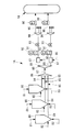
図2には、本開示の幾つかの実施形態に係る粉体燃料供給装置の一態様の微粉炭供給系統の概略構成が示されている。微粉炭供給系統1Aは、微粉炭供給ホッパ80(以下、単に「ホッパ80」という。)からガス化炉設備14に対して微粉炭を供給するように設けられている。ホッパ80は、複数(例えば、図2では3つ)設けられている。各ホッパ80は、使用時に1つずつ微粉炭が排出するよう切り替えられるようになっている。したがって、1つのホッパ80が微粉炭を排出中の場合は、他のホッパ80は排出に対して待機状態となる。ホッパ80には、上部圧力調整窒素系統81と、下部圧力調整窒素系統82と、流動化窒素系統83とが接続されている。
上部圧力調整窒素系統81は、ホッパ80の上部から窒素を供給するようになっており、ホッパ80の排出中においてガス化炉設備14の圧力容器内の圧力との差圧を一定に保つためのものである。
下部圧力調整窒素系統82は、微粉炭をホッパ80の底部にある払出し口へ送り出すための圧力をホッパ80内に付与するものである。
流動化窒素系統83は、搬送管84の入口周りの微粉炭を流動化するものである。
上部圧力調整窒素系統81と下部圧力調整窒素系統82と流動化窒素系統83とを加算して窒素比重で換算したものが、ホッパ80へ投入される窒素流量となる。
上部圧力調整窒素系統81と下部圧力調整窒素系統82と流動化窒素系統83とを加算して窒素比重で換算したものが、ホッパ80へ投入される窒素流量となる。
各ホッパ80には、搬送管(粉体搬送配管)84が接続されている。各搬送管84には、合流器86の手前の上流側で搬送管シール窒素系統85が接続されている。搬送管シール窒素系統85は、使用していないホッパ80に対応する搬送管84内の圧力を所定値以上に加圧するものである。これにより、使用していないホッパ80が大気に解放されていてもガス化炉設備14側に対してシールが行われるようになっている。
各搬送管84の下流端は、合流器86に接続されて合流するようになっている。合流器86は、合流搬送管87を介して分配器88に接続されている。分配器88には、複数(例えば、図2では2つ)の分配配管(粉体搬送配管)89が並列に接続されている。
各分配配管89には、上流側から順に、希釈窒素系統(追加不活性ガス供給部)90が接続されたミキシングチャンバ97、流量計91及びγ線密度計92、微粉炭流量調整弁93が設けられている。γ線密度計92は、混合ガス中の微粉炭の密度を計測できるものであればよく、γ線に限定するものではない。
希釈窒素系統90は、分配配管89内に追加的に希釈用の窒素である希釈窒素(追加不活性ガス)を供給して、微粉炭と窒素との混合ガスの管内流速を調整する。希釈窒素系統90の希釈窒素を合計した希釈窒素流量は、混合ガスの管内流速が所定の閾値以上となるように設定される。管内流速の閾値は、例えば、1.5m/s以上8m/s以下の範囲から設定され、希釈窒素流量で調整される。管内流速が、1.5m/s未満では微粉炭が配管内に沈降して搬送が不安定になり好ましくない。管内流速が、8m/sを超えると全体流速が速くなり過ぎて希釈窒素系統90の圧力損失の増加や配管摩耗の促進などが発生して好ましくない。よって、希釈窒素は、混合ガスの管内流速が所定の閾値未満の場合に分配配管89に供給される。
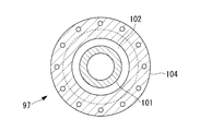
ミキシングチャンバ97は、分配配管89上に設けられており、粉体搬送配管の途中に設けられている。図4には、ミキシングチャンバ97の中心軸に沿った断面図が示されている。図4に示されるように、ミキシングチャンバ97は略円筒状であり、外管104とその内部に焼結金属フィルタ101を有する二重管構造である。外管104の入口及び出口が分配配管89に接続される。また希釈窒素系統90が外管104の鉛直方向上方に接続され、希釈窒素が供給される。例えばグランドパッキン102を介して焼結金属フィルタ101の円筒外側両端部分をシール及び支持されて、ミキシングチャンバ97の外管104内に円筒状の焼結金属フィルタ101が設置される。分配配管89からミキシングチャンバ97に流入する混合ガス(微粉炭と微粉炭に随伴して搬送される窒素ガスとが混合されたガス及び水分を含む)は全て焼結金属フィルタ101の円筒内部に流入する。
ミキシングチャンバ97と希釈窒素系統90との接続形態については、前述の形態に限らない。例えば、希釈窒素系統90がミキシングチャンバ97の鉛直方向下方に接続、または希釈窒素系統90がミキシングチャンバ97の水平方向に接続されていてもよい。
ミキシングチャンバ97と希釈窒素系統90との接続形態については、前述の形態に限らない。例えば、希釈窒素系統90がミキシングチャンバ97の鉛直方向下方に接続、または希釈窒素系統90がミキシングチャンバ97の水平方向に接続されていてもよい。
ミキシングチャンバ97は、搬送される微粉炭に対し、希釈窒素系統90から供給された希釈窒素を、所定の厚みを有した多孔質体からなる焼結金属フィルタ101を介して全周方向から投入するものである。これにより、略均一に窒素と微粉炭とが混ざり合った混合ガスが搬送される。
流量計91は、混合ガスの体積流量を計測する。γ線密度計92は、混合ガス中の微粉炭の密度を計測する。
微粉炭流量調整弁93は、開度制御され、分配配管89内を流れる混合ガスの流量を調整する。
各分配配管89の下流端は、それぞれ、バーナ分配器94に接続されている。バーナ分配器94には、複数(例えば、図2では4つ)の分岐管(粉体搬送配管)95が並列に接続されている。各分岐管95には、γ線密度計96が設けられている。各分岐管95の下流には、バーナが接続され、ガス化炉設備14のガス化炉壁内へ混合ガスが導かれる。γ線密度計96は、混合ガス中の微粉炭の密度を計測できるものであればよく、γ線に限定するものではない。
前述したように、希釈窒素系統90からの希釈窒素の供給は、管内流速が所定の閾値未満の場合に分配配管89のミキシングチャンバ97に供給される。例えば、石炭ガス化複合発電設備10の負荷が低くガス化炉への燃料供給量が低い場合に、管内流速が低下するため、希釈窒素系統90から希釈窒素が供給される。ガス化炉への燃料供給流量が高く管内流速が所定の閾値を満足している場合は、窒素の追加投入が必要ないため、希釈窒素系統90からの希釈窒素の供給は行われていなかった。
希釈窒素の供給がない場合に、対流などにより、ミキシングチャンバ97からミキシングチャンバ97に接続された希釈窒素系統90へ混合ガスが逆流する場合がある。混合ガスが水分を含んでいる場合、希釈窒素系統90へ逆流した水分は、希釈窒素系統90の配管を介して大気により冷却され、希釈窒素系統90の配管内で結露する。逆流した水分は、結露して液体の水となり、希釈窒素系統90内で滞留する。また希釈窒素系統90がミキシングチャンバ97への希釈窒素流れ方向の上方側に設置されているため、希釈窒素流れの流体力により水が希釈窒素系統90からミキシングチャンバ97へ移動する場合もある。
希釈窒素系統90内で滞留した水は、石炭ガス化複合発電設備10が停止した場合に管内パージをするために希釈窒素を供給する際などに、希釈窒素の流通開始とともにミキシングチャンバ97側へ移動する。移動した水は、ミキシングチャンバ97で滞留し、ミキシングチャンバ97内の焼結金属フィルタ101の円筒外側(希釈窒素系統90側)から焼結金属フィルタ101の円筒内側に付着する場合や、通過する場合がある。
円筒状の焼結金属フィルタ101の円筒外側から内側へと水を含む窒素ガスが通過すると、焼結金属フィルタ101の円筒内側(微粉炭搬送経路側)と円筒外側(外管104と焼結金属フィルタ101との間)に差圧が生じる。焼結金属フィルタ101に水を含む窒素ガスが通過することで差圧が上昇し続けると、その差圧により焼結金属フィルタ101が、円筒内側方向へ変形する可能性がある。
そこで、本実施形態では、ミキシングチャンバ97への水の搬入を抑制するために、希釈窒素系統90への混合ガスの逆流を抑制する。
希釈窒素系統90は、ミキシングチャンバ97へ所定流量の希釈窒素を常時供給する。すなわち、管内流量が所定の閾値未満となった場合にのみ希釈窒素系統90から供給されていた希釈窒素を、管内流量によらずミキシングチャンバ97へ常時所定流量供給する。
ここで、常時とは、管内流量が所定の閾値以上である時間帯を含む、微粉炭供給系統1A及び石炭ガス化複合発電設備10の運転および運転準備中によらない、完全な停止状態を除く全ての運転可能な時間であることを示す。
ここで、常時とは、管内流量が所定の閾値以上である時間帯を含む、微粉炭供給系統1A及び石炭ガス化複合発電設備10の運転および運転準備中によらない、完全な停止状態を除く全ての運転可能な時間であることを示す。
希釈窒素系統90から希釈窒素が供給され続けることで、ミキシングチャンバ97を流れる混合ガスは希釈窒素系統90側へ侵入することができないため、希釈窒素系統90への混合ガスの逆流が抑制される。
希釈窒素系統90からミキシングチャンバ97への希釈窒素の供給における所定流量は、ミキシングチャンバ97から希釈窒素系統90への混合ガスの逆流の発生を低減するような流量であってもよい。
以上、説明してきたように、本実施形態に係る粉体燃料供給装置、ガス化炉設備およびガス化複合発電設備ならびに粉体燃料供給装置の制御方法によれば、以下の作用効果を奏する。
微粉炭と窒素と水分とを含む混合ガスが搬送される搬送管84、分配配管89及び分岐管95と、混合ガスの流速が所定の閾値未満の場合にミキシングチャンバ97へ希釈窒素を追加供給する希釈窒素系統90とを備え、希釈窒素系統90は、ミキシングチャンバ97へ所定流量の希釈窒素を常時供給することから、水分を含む混合ガスが希釈窒素系統90に侵入することがなく、ミキシングチャンバ97から希釈窒素系統90へ混合ガスが逆流することを抑制することができる。
微粉炭と窒素と水分とを含む混合ガスが搬送される搬送管84、分配配管89及び分岐管95と、混合ガスの流速が所定の閾値未満の場合にミキシングチャンバ97へ希釈窒素を追加供給する希釈窒素系統90とを備え、希釈窒素系統90は、ミキシングチャンバ97へ所定流量の希釈窒素を常時供給することから、水分を含む混合ガスが希釈窒素系統90に侵入することがなく、ミキシングチャンバ97から希釈窒素系統90へ混合ガスが逆流することを抑制することができる。
運転中、混合ガスは分配配管89内で80℃程度に加温された状態で流通している。一方、希釈窒素系統90は、窒素供給がない場合は、大気温度程度であり、混合ガスと比較すると温度が低い。
水分を含む混合ガスは、加温された状態であるため水分も気体となって含まれている。この混合ガスに含まれる水分が大気温度程度の希釈窒素系統90へ逆流して侵入すると、冷却されて液体となり、希釈窒素系統90内で結露して水となる。希釈窒素系統90内で結露した水は、希釈窒素系統90内に滞留する。例えば停止時など混合ガスの流速が所定の閾値未満となると、希釈窒素が希釈窒素系統90からミキシングチャンバ97へ供給されて混合ガスの流速を上昇させるが、この際、希釈窒素系統90内で結露した水が滞留していると希釈窒素とともにミキシングチャンバ97へ供給されることとなる。
水分を含む混合ガスは、加温された状態であるため水分も気体となって含まれている。この混合ガスに含まれる水分が大気温度程度の希釈窒素系統90へ逆流して侵入すると、冷却されて液体となり、希釈窒素系統90内で結露して水となる。希釈窒素系統90内で結露した水は、希釈窒素系統90内に滞留する。例えば停止時など混合ガスの流速が所定の閾値未満となると、希釈窒素が希釈窒素系統90からミキシングチャンバ97へ供給されて混合ガスの流速を上昇させるが、この際、希釈窒素系統90内で結露した水が滞留していると希釈窒素とともにミキシングチャンバ97へ供給されることとなる。
ミキシングチャンバ97へ供給された水は滞留し、ミキシングチャンバ97内の焼結金属フィルタ101に付着する場合や、焼結金属フィルタ101を通過する場合がある。水を含む窒素ガスが焼結金属フィルタ101を通過すると、焼結金属フィルタ101が水により部分的な閉塞や通過抵抗の増加を起こす。このため、外管104と焼結金属フィルタ101の円筒外側の間の圧力が、焼結金属フィルタ101の円筒内部の圧力よりも高くなり、差圧の増加が生じる。差圧の増加が発生し続けると、その圧力差により焼結金属フィルタ101には円筒内部側方向への変形が発生する可能性がある。
本実施形態によれば、混合ガス及び混合ガスに含まれる水分を希釈窒素系統90に逆流するのを防ぐため、希釈窒素系統90内で水分が結露して水にならず、結露した水がミキシングチャンバ97側へ搬送されず、また焼結金属フィルタ101への水の付着や通過が発生しないため、差圧の増加が生じることがなく、焼結金属フィルタ101の変形を抑制することができる。
また、常に所定流量で希釈窒素を供給し続けるという簡易な構成で焼結金属フィルタ101の変形を抑制することができる。
また、常に所定流量で希釈窒素を供給し続けるという簡易な構成で焼結金属フィルタ101の変形を抑制することができる。
また本実施形態によれば、希釈窒素の所定流量は、ミキシングチャンバ97から希釈窒素系統90への混合ガスの逆流の発生を低減する流量である。このことから、希釈窒素流量を最小限にとどめることができる。また、希釈窒素系統90への混合ガスの逆流の発生を未然に防ぐことができる。
上記した実施形態では、常時希釈窒素をミキシングチャンバへ所定流量供給するとしたが、本実施形態では、さらに希釈窒素系統を加熱するものである。その他の点については上記した実施形態と同様であるので、同様の構成については同一符号を付しその説明は省略する。
図3には、本開示の幾つかの実施形態に係る粉体燃料供給装置の一態様の希釈窒素系統の概略構成図が示されている。
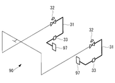
図3に示されるように、希釈窒素系統90は、例えば2つの分配配管89にそれぞれ設けられたミキシングチャンバ97へ希釈窒素を供給するように構成されている。希釈窒素系統90上には、希釈窒素流量調整弁32と、希釈窒素流量調整弁32からミキシングチャンバ97までの間の配管(図3の太線部)の加熱を行う熱源31とが備えられている。ここで、熱源31は、例えばスチームトレース、電気トレースなど、希釈窒素系統90を昇温させる(加熱する)装置であればよく、その構成は問わない。
図3に示されるように、希釈窒素系統90は、例えば2つの分配配管89にそれぞれ設けられたミキシングチャンバ97へ希釈窒素を供給するように構成されている。希釈窒素系統90上には、希釈窒素流量調整弁32と、希釈窒素流量調整弁32からミキシングチャンバ97までの間の配管(図3の太線部)の加熱を行う熱源31とが備えられている。ここで、熱源31は、例えばスチームトレース、電気トレースなど、希釈窒素系統90を昇温させる(加熱する)装置であればよく、その構成は問わない。
熱源31は、希釈窒素系統90内を流通する希釈窒素を大気温度以上に加熱する。さらには逆流した混合ガスに含まれる水分が希釈窒素系統90内で結露しない温度、または混合ガスに含まれた水分が気化する飽和温度以上に加熱してもよい。
以上、説明してきたように、本実施形態に係る粉体燃料供給装置、ガス化炉設備およびガス化複合発電設備ならびに粉体燃料供給装置の制御方法によれば、以下の作用効果を奏する。
希釈窒素系統90は、熱源31により加熱されることから、水分を含む混合ガスが希釈窒素系統90へ逆流した場合であっても、希釈窒素系統90内で結露して水になるのを防ぐことができる。さらには、混合ガスに含まれる水分を気体(水蒸気)のままとすることができる。水蒸気は、希釈窒素がミキシングチャンバ97へ供給される際に、希釈窒素及び混合ガスとともにミキシングチャンバ97へ搬送される。よって、希釈窒素系統90及びミキシングチャンバ97への水の滞留を抑制することができる。
希釈窒素系統90は、熱源31により加熱されることから、水分を含む混合ガスが希釈窒素系統90へ逆流した場合であっても、希釈窒素系統90内で結露して水になるのを防ぐことができる。さらには、混合ガスに含まれる水分を気体(水蒸気)のままとすることができる。水蒸気は、希釈窒素がミキシングチャンバ97へ供給される際に、希釈窒素及び混合ガスとともにミキシングチャンバ97へ搬送される。よって、希釈窒素系統90及びミキシングチャンバ97への水の滞留を抑制することができる。
上記した実施形態では、希釈窒素系統を加熱するとしたが、本実施形態では、希釈窒素系統からドレンを排出するものである。その他の点については上記した実施形態と同様であるので、同様の構成については同一符号を付しその説明は省略する。
図3には、本開示の幾つかの実施形態に係る粉体燃料供給装置の一態様の希釈窒素系統の概略構成図が示されている。
図3に示されるように、希釈窒素系統90は、例えば2つの分配配管89にそれぞれ設けられたミキシングチャンバ97へ希釈窒素を供給するように構成されている。希釈窒素系統90上には、希釈窒素流量調整弁32と、希釈窒素系統90に滞留した水を排出可能なドレン排出部33が備えられている。
図3に示されるように、希釈窒素系統90は、例えば2つの分配配管89にそれぞれ設けられたミキシングチャンバ97へ希釈窒素を供給するように構成されている。希釈窒素系統90上には、希釈窒素流量調整弁32と、希釈窒素系統90に滞留した水を排出可能なドレン排出部33が備えられている。
ドレン排出部33は、ミキシングチャンバ97から希釈窒素系統90へ逆流し、大気により冷却され結露して滞留した水を排出可能とする。ドレン排出部33は、例えば、希釈窒素系統90上において希釈窒素の流れ方向の最下部に設けることで、効果的に水を排出することができる。ミキシングチャンバ97から希釈窒素系統90へ逆流し、結露して滞留した水は、重力によりドレン排出部33方向に流れ、ドレン排出部33から排出される。
以上、説明してきたように、本実施形態に係る粉体燃料供給装置、ガス化炉設備およびガス化複合発電設備ならびに粉体燃料供給装置の制御方法によれば、以下の作用効果を奏する。
希釈窒素系統90は、ドレンを排出するドレン排出部33を備えることから、水分を含む混合ガスが希釈窒素系統90へ逆流し、混合ガスに含まれる水分が希釈窒素系統90内で結露して水になった場合であっても、ミキシングチャンバ97に搬送される前に水をドレンとして希釈窒素系統90のドレン排出部33から排出することができる。希釈窒素系統90からドレンが排出されるため、ミキシングチャンバ97に水が搬送され、滞留するのを未然に防ぐことができる。
希釈窒素系統90は、ドレンを排出するドレン排出部33を備えることから、水分を含む混合ガスが希釈窒素系統90へ逆流し、混合ガスに含まれる水分が希釈窒素系統90内で結露して水になった場合であっても、ミキシングチャンバ97に搬送される前に水をドレンとして希釈窒素系統90のドレン排出部33から排出することができる。希釈窒素系統90からドレンが排出されるため、ミキシングチャンバ97に水が搬送され、滞留するのを未然に防ぐことができる。
上記した実施形態では、希釈窒素系統からドレンを排出するとしたが、本実施形態では、焼結金属フィルタに補強用の中間リングを設置するものである。その他の点については上記した実施形態と同様であるので、同様の構成については同一符号を付しその説明は省略する。
図4には、本開示の幾つかの実施形態に係る粉体燃料供給装置の一態様のミキシングチャンバの中心軸に沿った断面図が示されている。また図5には、本開示の幾つかの実施形態に係る粉体燃料供給装置の一態様のミキシングチャンバの一端側の側面図が示されている。
前述したように、ミキシングチャンバ97は略円筒状であり、入口及び出口が分配配管89に接続される。また本実施形態では、例えば希釈窒素系統90がミキシングチャンバ97の鉛直方向上方側に接続され、希釈窒素が供給される。ミキシングチャンバ97内には、円筒状で所定の厚みを有した多孔質体からなる焼結金属フィルタ101が例えばグランドパッキン102を介して支持されて設置される。図5に示されるように、分配配管89からミキシングチャンバ97に流入する混合ガスは全て焼結金属フィルタ101内に流入する。
前述したように、ミキシングチャンバ97は略円筒状であり、入口及び出口が分配配管89に接続される。また本実施形態では、例えば希釈窒素系統90がミキシングチャンバ97の鉛直方向上方側に接続され、希釈窒素が供給される。ミキシングチャンバ97内には、円筒状で所定の厚みを有した多孔質体からなる焼結金属フィルタ101が例えばグランドパッキン102を介して支持されて設置される。図5に示されるように、分配配管89からミキシングチャンバ97に流入する混合ガスは全て焼結金属フィルタ101内に流入する。
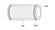
図6には、本開示の幾つかの実施形態に係る粉体燃料供給装置の一態様ミキシングチャンバの焼結金属フィルタの一部の概略図が示されている。
図4及び図6に示されるように、焼結金属フィルタ101は、ミキシングチャンバ97内に複数個(図4では例として3個)設置されている。焼結金属フィルタ101は、ミキシングチャンバ97の中心軸方向の全長よりも短い長さであり、その混合ガス搬送入口側及び出口側はいずれも中間リング103が焼結金属フィルタ101の外周部101aを介して接続固定されている。これを図4に示されるように中心軸に沿って中間リング103と焼結金属フィルタ101とを交互に接続固定することで、ミキシングチャンバ97の全長と同じ長さの1つの焼結金属フィルタ101を形成している。焼結金属フィルタ101と中間リング103との接続は、例えば溶接により固定される。
図4及び図6に示されるように、焼結金属フィルタ101は、ミキシングチャンバ97内に複数個(図4では例として3個)設置されている。焼結金属フィルタ101は、ミキシングチャンバ97の中心軸方向の全長よりも短い長さであり、その混合ガス搬送入口側及び出口側はいずれも中間リング103が焼結金属フィルタ101の外周部101aを介して接続固定されている。これを図4に示されるように中心軸に沿って中間リング103と焼結金属フィルタ101とを交互に接続固定することで、ミキシングチャンバ97の全長と同じ長さの1つの焼結金属フィルタ101を形成している。焼結金属フィルタ101と中間リング103との接続は、例えば溶接により固定される。
中間リング103は、例えばステンレス鋼製であり、焼結金属フィルタ101に比べて高強度を示し、応力負荷に対して変形しにくいものである。ミキシングチャンバ97内に設置される焼結金属フィルタ101の製造工程においては、ミキシングチャンバ97の全長と略同じ長さの焼結金属フィルタ101を2箇所以上で切断し、その切断箇所に中間リング103を溶接固定すればよい。ただし、製造工程は上記のみによらず、他の工程を採用することもできる。
中間リング103は、直径方向に幅を持つリング状の部材である。本実施形態では、中間リング103の直径方向の幅と、焼結金属フィルタ101の直径方向の厚みとは同じであるとする。
中間リング103は、直径方向に幅を持つリング状の部材である。本実施形態では、中間リング103の直径方向の幅と、焼結金属フィルタ101の直径方向の厚みとは同じであるとする。
以上、説明してきたように、本実施形態に係る粉体燃料供給装置、ガス化炉設備およびガス化複合発電設備ならびに粉体燃料供給装置の制御方法によれば、以下の作用効果を奏する。
ミキシングチャンバ97は、円筒状で所定の厚みを有した多孔質体からなる複数の焼結金属フィルタ101と、各焼結金属フィルタ101の外周部101aに接続固定された中間リング103とを有し、複数の焼結金属フィルタ101の中心軸と中間リング103の中心軸とがミキシングチャンバ97の中心軸方向に沿って設けられていることから、短尺の円筒状の焼結金属フィルタ101を中間リング103で接続し、1つの長尺の円筒状の焼結金属フィルタ101として使用することができる。これにより、1本の焼結金属フィルタ101のみでミキシングチャンバ97のフィルタを構成する場合と比べて、各焼結金属フィルタ101の長さが短くなるとともに、焼結金属フィルタ101の両端部分は中間リング103により補強される。そのため、焼結金属フィルタ101の中心軸方向に対して垂直方向の圧力に対する強度を高めることができる。水分を含む混合ガスが希釈窒素系統90へ逆流して水分が結露して水になり、この水がミキシングチャンバ97側へ搬送されて滞留したとしても、焼結金属フィルタ101に付着する水や、通過する水に起因する差圧が増加することによる焼結金属フィルタ101の変形を最小限にとどめることができる。
また、焼結金属フィルタ101が変形した場合に、対象の短尺の焼結金属フィルタ101のみを交換すればよいため、交換に要するコストを削減することができる。
ミキシングチャンバ97は、円筒状で所定の厚みを有した多孔質体からなる複数の焼結金属フィルタ101と、各焼結金属フィルタ101の外周部101aに接続固定された中間リング103とを有し、複数の焼結金属フィルタ101の中心軸と中間リング103の中心軸とがミキシングチャンバ97の中心軸方向に沿って設けられていることから、短尺の円筒状の焼結金属フィルタ101を中間リング103で接続し、1つの長尺の円筒状の焼結金属フィルタ101として使用することができる。これにより、1本の焼結金属フィルタ101のみでミキシングチャンバ97のフィルタを構成する場合と比べて、各焼結金属フィルタ101の長さが短くなるとともに、焼結金属フィルタ101の両端部分は中間リング103により補強される。そのため、焼結金属フィルタ101の中心軸方向に対して垂直方向の圧力に対する強度を高めることができる。水分を含む混合ガスが希釈窒素系統90へ逆流して水分が結露して水になり、この水がミキシングチャンバ97側へ搬送されて滞留したとしても、焼結金属フィルタ101に付着する水や、通過する水に起因する差圧が増加することによる焼結金属フィルタ101の変形を最小限にとどめることができる。
また、焼結金属フィルタ101が変形した場合に、対象の短尺の焼結金属フィルタ101のみを交換すればよいため、交換に要するコストを削減することができる。
以上、本発明の各実施形態について図面を参照して詳述してきたが、具体的な構成はこの実施形態に限られるものではない。たとえば、各実施形態を適宜組み合わせて実施してもよい。これにより、さらに希釈窒素系統90に逆流した水分の焼結金属フィルタ101への滞留を防ぐことができる。
1A 微粉炭供給系統(粉体燃料供給装置)
10 石炭ガス化複合発電設備(ガス化複合発電設備)
11 給炭設備
11a 給炭ライン
14 ガス化炉設備
15 チャー回収設備
16 ガス精製設備
17 ガスタービン
18 蒸気タービン
19 発電機
20 排熱回収ボイラ
33 ドレン排出部
41 圧縮空気供給ライン
42 空気分離設備
43 第1窒素供給ライン
45 第2窒素供給ライン
46 チャー戻しライン
47 酸素供給ライン
49 ガス生成ライン
51 集塵設備
52 供給ホッパ
53 ガス排出ライン
61 圧縮機
62 燃焼器
63 タービン
64 回転軸
65 圧縮空気供給ライン
66 燃料ガス供給ライン
67 燃焼ガス供給ライン
68 昇圧機
69 タービン
70 排ガスライン
71 蒸気供給ライン
72 蒸気回収ライン
74 ガス浄化設備
75 煙突
80 微粉炭供給ホッパ
81 上部圧力調整窒素系統
82 下部圧力調整窒素系統
83 流動化窒素系統
84 搬送管(粉体搬送配管)
85 搬送管シール窒素系統
86 合流器
87 合流搬送管
88 分配器
89 分配配管(粉体搬送配管)
90 希釈窒素系統(追加不活性ガス供給部)
91 流量計
92 γ線密度計
93 微粉炭流量調整弁
94 バーナ分配器
95 分岐管(粉体搬送配管)
96 γ線密度計
97 ミキシングチャンバ
101 焼結金属フィルタ
101a 外周部
102 グランドパッキン
103 中間リング
10 石炭ガス化複合発電設備(ガス化複合発電設備)
11 給炭設備
11a 給炭ライン
14 ガス化炉設備
15 チャー回収設備
16 ガス精製設備
17 ガスタービン
18 蒸気タービン
19 発電機
20 排熱回収ボイラ
33 ドレン排出部
41 圧縮空気供給ライン
42 空気分離設備
43 第1窒素供給ライン
45 第2窒素供給ライン
46 チャー戻しライン
47 酸素供給ライン
49 ガス生成ライン
51 集塵設備
52 供給ホッパ
53 ガス排出ライン
61 圧縮機
62 燃焼器
63 タービン
64 回転軸
65 圧縮空気供給ライン
66 燃料ガス供給ライン
67 燃焼ガス供給ライン
68 昇圧機
69 タービン
70 排ガスライン
71 蒸気供給ライン
72 蒸気回収ライン
74 ガス浄化設備
75 煙突
80 微粉炭供給ホッパ
81 上部圧力調整窒素系統
82 下部圧力調整窒素系統
83 流動化窒素系統
84 搬送管(粉体搬送配管)
85 搬送管シール窒素系統
86 合流器
87 合流搬送管
88 分配器
89 分配配管(粉体搬送配管)
90 希釈窒素系統(追加不活性ガス供給部)
91 流量計
92 γ線密度計
93 微粉炭流量調整弁
94 バーナ分配器
95 分岐管(粉体搬送配管)
96 γ線密度計
97 ミキシングチャンバ
101 焼結金属フィルタ
101a 外周部
102 グランドパッキン
103 中間リング
Claims (8)
- 粉体燃料と該粉体燃料に随伴して搬送される随伴不活性ガスとが混合されたガス及び水分を含む混合ガスが搬送される粉体搬送配管と、
前記混合ガスの流速が所定の閾値未満の場合に、前記粉体搬送配管に接続され該粉体搬送配管の途中に配置されたミキシングチャンバへ追加不活性ガスを追加供給する追加不活性ガス供給部と、
を備え、
前記追加不活性ガス供給部は、前記ミキシングチャンバへ所定流量の前記追加不活性ガスを常時供給する粉体燃料供給装置。 - 前記追加不活性ガスの前記所定流量は、前記ミキシングチャンバから前記追加不活性ガス供給部への前記混合ガスの逆流の発生を抑制する流量である請求項1に記載の粉体燃料供給装置。
- 前記追加不活性ガス供給部は、熱源により前記混合ガスに含まれる水分の飽和温度以上の状態に加熱された請求項1または2に記載の粉体燃料供給装置。
- 前記追加不活性ガス供給部は、ドレンを排出するドレン排出部を備える請求項1から請求項3のいずれかに記載の粉体燃料供給装置。
- 前記ミキシングチャンバは、
それぞれ円筒状で、所定の厚みを有した多孔質体からなる複数の焼結金属フィルタと、
複数の前記焼結金属フィルタの外周部に接続固定された環状の中間リングと、
を有し、
複数の前記焼結金属フィルタの中心軸と前記中間リングの中心軸とは、前記ミキシングチャンバの中心軸方向に沿って設けられている請求項1から請求項4のいずれかに記載の粉体燃料供給装置。 - 請求項1から5のいずれかに記載の粉体燃料供給装置と、
該粉体燃料供給装置から粉体燃料が供給され前記粉体燃料をガス化するガス化炉と、
を備えているガス化炉設備。 - 請求項6に記載のガス化炉設備と、
前記ガス化炉設備で生成した生成ガスの少なくとも一部を燃焼させることで回転駆動するガスタービンと、
前記ガスタービンから排出されたタービン排ガスを導入する排熱回収ボイラで生成した蒸気により回転駆動する蒸気タービンと、
前記ガスタービンおよび/または前記蒸気タービンの回転駆動に連結された発電機と、
を備えているガス化複合発電設備。 - 粉体燃料と該粉体燃料に随伴して搬送される随伴不活性ガスとが混合されたガス及び水分を含む混合ガスが搬送される粉体搬送配管と、
前記混合ガスの流速が所定の閾値未満の場合に、前記粉体搬送配管に接続され該粉体搬送配管の途中に配置されたミキシングチャンバへ追加不活性ガスを追加供給する追加不活性ガス供給部と、
を備えた粉体燃料供給装置の制御方法であって、
前記追加不活性ガス供給部は、前記ミキシングチャンバへの所定流量の前記追加不活性ガスを常時供給するステップを有する粉体燃料供給装置の制御方法。
Priority Applications (2)
| Application Number | Priority Date | Filing Date | Title |
|---|---|---|---|
| US17/269,046 US12163098B2 (en) | 2018-11-14 | 2019-11-08 | Powder fuel feed apparatus, gasifier unit, and integrated gasification combined cycle and control method of powder fuel feed apparatus |
| CN201980054158.8A CN112585404A (zh) | 2018-11-14 | 2019-11-08 | 粉体燃料供给装置、气化炉设备及气化复合发电设备以及粉体燃料供给装置的控制方法 |
Applications Claiming Priority (2)
| Application Number | Priority Date | Filing Date | Title |
|---|---|---|---|
| JP2018-213666 | 2018-11-14 | ||
| JP2018213666A JP7362244B2 (ja) | 2018-11-14 | 2018-11-14 | 粉体燃料供給装置、ガス化炉設備およびガス化複合発電設備ならびに粉体燃料供給装置の制御方法 |
Publications (1)
| Publication Number | Publication Date |
|---|---|
| WO2020100746A1 true WO2020100746A1 (ja) | 2020-05-22 |
Family
ID=70730273
Family Applications (1)
| Application Number | Title | Priority Date | Filing Date |
|---|---|---|---|
| PCT/JP2019/043921 Ceased WO2020100746A1 (ja) | 2018-11-14 | 2019-11-08 | 粉体燃料供給装置、ガス化炉設備およびガス化複合発電設備ならびに粉体燃料供給装置の制御方法 |
Country Status (4)
| Country | Link |
|---|---|
| US (1) | US12163098B2 (ja) |
| JP (1) | JP7362244B2 (ja) |
| CN (1) | CN112585404A (ja) |
| WO (1) | WO2020100746A1 (ja) |
Families Citing this family (2)
| Publication number | Priority date | Publication date | Assignee | Title |
|---|---|---|---|---|
| US11519601B2 (en) * | 2020-03-10 | 2022-12-06 | General Electric Company | System and method for inerting a biomass feed assembly |
| CN115506892B (zh) * | 2022-09-01 | 2024-08-02 | 西安近代化学研究所 | 粉末燃料供给系统的分级流化结构 |
Citations (12)
| Publication number | Priority date | Publication date | Assignee | Title |
|---|---|---|---|---|
| JPS5292928A (en) * | 1976-01-31 | 1977-08-04 | Mitsui Eng & Shipbuild Co Ltd | Boiler for combustion of purverized coal |
| JPS5824819A (ja) * | 1981-07-17 | 1983-02-14 | ブレンシユトフインステイトウ−ト・フライベルク | 質量流量を調節する方法 |
| JPS6357425A (ja) * | 1986-08-22 | 1988-03-12 | Mitsubishi Heavy Ind Ltd | 逆流防止装置 |
| JPS63267814A (ja) * | 1987-04-24 | 1988-11-04 | Babcock Hitachi Kk | 微粉炭燃焼方法 |
| JPH0395319U (ja) * | 1990-01-17 | 1991-09-27 | ||
| JP2001347310A (ja) * | 2000-06-07 | 2001-12-18 | Toshiba Corp | 二重管型熱交換器および二重伝熱管製造方法 |
| JP2005255508A (ja) * | 2004-03-08 | 2005-09-22 | Fukuhara Co Ltd | 窒素ガスの製造方法および製造装置 |
| JP2008524088A (ja) * | 2004-12-17 | 2008-07-10 | シエル・インターナシヨネイル・リサーチ・マーチヤツピイ・ベー・ウイ | 固体粒状材料の搬送用パイプ部品 |
| JP2012126571A (ja) * | 2010-11-25 | 2012-07-05 | Mitsubishi Heavy Ind Ltd | ビンシステム及びチャー回収装置 |
| JP2014159935A (ja) * | 2013-02-20 | 2014-09-04 | Mitsubishi Heavy Ind Ltd | 燃料加工設備 |
| WO2017138488A1 (ja) * | 2016-02-08 | 2017-08-17 | 三菱日立パワーシステムズ株式会社 | 粉体供給ホッパの加圧システム、ガス化設備およびガス化複合発電設備ならびに粉体供給ホッパの加圧方法 |
| JP2017146022A (ja) * | 2016-02-17 | 2017-08-24 | 三菱日立パワーシステムズ株式会社 | 微粉燃料供給装置及び方法、ガス化複合発電設備 |
Family Cites Families (8)
| Publication number | Priority date | Publication date | Assignee | Title |
|---|---|---|---|---|
| JPH0617741B2 (ja) | 1985-09-13 | 1994-03-09 | バブコツク日立株式会社 | ボイラ用微粉炭機出口の一次空気温度の制御方法 |
| US5666800A (en) * | 1994-06-14 | 1997-09-16 | Air Products And Chemicals, Inc. | Gasification combined cycle power generation process with heat-integrated chemical production |
| US5827370A (en) * | 1997-01-13 | 1998-10-27 | Mks Instruments, Inc. | Method and apparatus for reducing build-up of material on inner surface of tube downstream from a reaction furnace |
| US6227768B1 (en) * | 1999-09-30 | 2001-05-08 | Xerox Corporation | Particulate conveyor device and apparatus |
| US6513317B2 (en) | 2001-01-11 | 2003-02-04 | General Electric Company | Apparatus for controlling nitrogen injection into gas turbine |
| JP4508443B2 (ja) | 2001-02-22 | 2010-07-21 | 電源開発株式会社 | 石炭ガス化発電プラント |
| US6722822B2 (en) * | 2002-08-20 | 2004-04-20 | The Young Industries, Inc. | System for pneumatically conveying bulk particulate materials |
| CN206848008U (zh) * | 2017-07-10 | 2018-01-05 | 天津市众航环保科技有限公司 | 一种固定源排放颗粒污染物采集装置 |
-
2018
- 2018-11-14 JP JP2018213666A patent/JP7362244B2/ja active Active
-
2019
- 2019-11-08 CN CN201980054158.8A patent/CN112585404A/zh active Pending
- 2019-11-08 WO PCT/JP2019/043921 patent/WO2020100746A1/ja not_active Ceased
- 2019-11-08 US US17/269,046 patent/US12163098B2/en active Active
Patent Citations (12)
| Publication number | Priority date | Publication date | Assignee | Title |
|---|---|---|---|---|
| JPS5292928A (en) * | 1976-01-31 | 1977-08-04 | Mitsui Eng & Shipbuild Co Ltd | Boiler for combustion of purverized coal |
| JPS5824819A (ja) * | 1981-07-17 | 1983-02-14 | ブレンシユトフインステイトウ−ト・フライベルク | 質量流量を調節する方法 |
| JPS6357425A (ja) * | 1986-08-22 | 1988-03-12 | Mitsubishi Heavy Ind Ltd | 逆流防止装置 |
| JPS63267814A (ja) * | 1987-04-24 | 1988-11-04 | Babcock Hitachi Kk | 微粉炭燃焼方法 |
| JPH0395319U (ja) * | 1990-01-17 | 1991-09-27 | ||
| JP2001347310A (ja) * | 2000-06-07 | 2001-12-18 | Toshiba Corp | 二重管型熱交換器および二重伝熱管製造方法 |
| JP2005255508A (ja) * | 2004-03-08 | 2005-09-22 | Fukuhara Co Ltd | 窒素ガスの製造方法および製造装置 |
| JP2008524088A (ja) * | 2004-12-17 | 2008-07-10 | シエル・インターナシヨネイル・リサーチ・マーチヤツピイ・ベー・ウイ | 固体粒状材料の搬送用パイプ部品 |
| JP2012126571A (ja) * | 2010-11-25 | 2012-07-05 | Mitsubishi Heavy Ind Ltd | ビンシステム及びチャー回収装置 |
| JP2014159935A (ja) * | 2013-02-20 | 2014-09-04 | Mitsubishi Heavy Ind Ltd | 燃料加工設備 |
| WO2017138488A1 (ja) * | 2016-02-08 | 2017-08-17 | 三菱日立パワーシステムズ株式会社 | 粉体供給ホッパの加圧システム、ガス化設備およびガス化複合発電設備ならびに粉体供給ホッパの加圧方法 |
| JP2017146022A (ja) * | 2016-02-17 | 2017-08-24 | 三菱日立パワーシステムズ株式会社 | 微粉燃料供給装置及び方法、ガス化複合発電設備 |
Also Published As
| Publication number | Publication date |
|---|---|
| US20210238490A1 (en) | 2021-08-05 |
| JP7362244B2 (ja) | 2023-10-17 |
| US12163098B2 (en) | 2024-12-10 |
| JP2020079687A (ja) | 2020-05-28 |
| CN112585404A (zh) | 2021-03-30 |
Similar Documents
| Publication | Publication Date | Title |
|---|---|---|
| CN103826999B (zh) | 储藏室系统及炭回收装置 | |
| KR101192960B1 (ko) | 고점결성탄용 버너 및 가스화 노 | |
| JP5046887B2 (ja) | 高粘結性炭用バーナ及びガス化炉 | |
| CN111741913B (zh) | 粉体供给料斗加压装置、气化炉设备及气化复合发电设备以及粉体供给料斗加压装置的控制方法 | |
| CN104619621A (zh) | 粉体输送装置及煤焦回收装置 | |
| CN105143414B (zh) | 产生无颗粒的冷却合成气的方法和系统 | |
| WO2017138488A1 (ja) | 粉体供給ホッパの加圧システム、ガス化設備およびガス化複合発電設備ならびに粉体供給ホッパの加圧方法 | |
| KR101598768B1 (ko) | 가스화 장치 | |
| JP7362244B2 (ja) | 粉体燃料供給装置、ガス化炉設備およびガス化複合発電設備ならびに粉体燃料供給装置の制御方法 | |
| JP6607817B2 (ja) | ガス化炉装置及びガス化複合発電設備 | |
| JP5896777B2 (ja) | チャー回収装置 | |
| JP7191528B2 (ja) | 粉体燃料供給装置、ガス化炉設備およびガス化複合発電設備ならびに粉体燃料供給装置の制御方法 | |
| US11401476B2 (en) | Aftertreatment arrangement and method for the aftertreatment of at least gases downstream of a fluid bed gasification system, and logic unit and use | |
| WO2017104620A1 (ja) | チャー排出装置、これを有するチャー回収装置及びチャー排出方法、ガス化複合発電設備 | |
| JP6682420B2 (ja) | 配管部材、ガス化複合発電装置、配管部材の組立方法 | |
| JP2017095635A (ja) | ガス化装置、ガス化複合発電設備、ガス化設備及び除煤方法 | |
| US10808191B2 (en) | Gasification apparatus, control device, integrated gasification combined cycle, and control method | |
| JP7123569B2 (ja) | 粉体燃料供給装置、ガス化炉設備およびガス化複合発電設備ならびに粉体燃料供給装置の制御方法 | |
| JP7134637B2 (ja) | ガス化炉設備及びこれを備えたガス化複合発電設備並びにガス化炉設備の製造方法及び生成ガスの排出方法 | |
| JPH0729692B2 (ja) | 粒子状物質と流体との混合物を搬送する装置及び方法 | |
| JPH0581637B2 (ja) | ||
| JP2019143099A (ja) | 粉体燃料供給装置、ガス化炉設備およびガス化複合発電設備ならびに粉体燃料供給装置の制御方法 | |
| JP6576845B2 (ja) | 異物除去装置、ガス化設備およびガス化複合発電設備ならびに異物除去方法 | |
| JP2024173487A (ja) | ガス化炉設備、ガス化複合発電設備及びガス化炉設備の運転方法 |
Legal Events
| Date | Code | Title | Description |
|---|---|---|---|
| 121 | Ep: the epo has been informed by wipo that ep was designated in this application |
Ref document number: 19883955 Country of ref document: EP Kind code of ref document: A1 |
|
| NENP | Non-entry into the national phase |
Ref country code: DE |
|
| 122 | Ep: pct application non-entry in european phase |
Ref document number: 19883955 Country of ref document: EP Kind code of ref document: A1 |