WO2020100604A1 - 内燃機関の制御装置 - Google Patents
内燃機関の制御装置 Download PDFInfo
- Publication number
- WO2020100604A1 WO2020100604A1 PCT/JP2019/042679 JP2019042679W WO2020100604A1 WO 2020100604 A1 WO2020100604 A1 WO 2020100604A1 JP 2019042679 W JP2019042679 W JP 2019042679W WO 2020100604 A1 WO2020100604 A1 WO 2020100604A1
- Authority
- WO
- WIPO (PCT)
- Prior art keywords
- internal combustion
- period
- combustion engine
- control
- state
- Prior art date
Links
Images


Classifications
-
- F—MECHANICAL ENGINEERING; LIGHTING; HEATING; WEAPONS; BLASTING
- F02—COMBUSTION ENGINES; HOT-GAS OR COMBUSTION-PRODUCT ENGINE PLANTS
- F02D—CONTROLLING COMBUSTION ENGINES
- F02D41/00—Electrical control of supply of combustible mixture or its constituents
- F02D41/02—Circuit arrangements for generating control signals
- F02D41/04—Introducing corrections for particular operating conditions
- F02D41/047—Taking into account fuel evaporation or wall wetting
-
- F—MECHANICAL ENGINEERING; LIGHTING; HEATING; WEAPONS; BLASTING
- F02—COMBUSTION ENGINES; HOT-GAS OR COMBUSTION-PRODUCT ENGINE PLANTS
- F02D—CONTROLLING COMBUSTION ENGINES
- F02D41/00—Electrical control of supply of combustible mixture or its constituents
- F02D41/008—Controlling each cylinder individually
- F02D41/0087—Selective cylinder activation, i.e. partial cylinder operation
-
- F—MECHANICAL ENGINEERING; LIGHTING; HEATING; WEAPONS; BLASTING
- F02—COMBUSTION ENGINES; HOT-GAS OR COMBUSTION-PRODUCT ENGINE PLANTS
- F02D—CONTROLLING COMBUSTION ENGINES
- F02D13/00—Controlling the engine output power by varying inlet or exhaust valve operating characteristics, e.g. timing
- F02D13/02—Controlling the engine output power by varying inlet or exhaust valve operating characteristics, e.g. timing during engine operation
- F02D13/0203—Variable control of intake and exhaust valves
- F02D13/0215—Variable control of intake and exhaust valves changing the valve timing only
- F02D13/0219—Variable control of intake and exhaust valves changing the valve timing only by shifting the phase, i.e. the opening periods of the valves are constant
-
- F—MECHANICAL ENGINEERING; LIGHTING; HEATING; WEAPONS; BLASTING
- F02—COMBUSTION ENGINES; HOT-GAS OR COMBUSTION-PRODUCT ENGINE PLANTS
- F02D—CONTROLLING COMBUSTION ENGINES
- F02D17/00—Controlling engines by cutting out individual cylinders; Rendering engines inoperative or idling
-
- F—MECHANICAL ENGINEERING; LIGHTING; HEATING; WEAPONS; BLASTING
- F02—COMBUSTION ENGINES; HOT-GAS OR COMBUSTION-PRODUCT ENGINE PLANTS
- F02D—CONTROLLING COMBUSTION ENGINES
- F02D29/00—Controlling engines, such controlling being peculiar to the devices driven thereby, the devices being other than parts or accessories essential to engine operation, e.g. controlling of engines by signals external thereto
- F02D29/02—Controlling engines, such controlling being peculiar to the devices driven thereby, the devices being other than parts or accessories essential to engine operation, e.g. controlling of engines by signals external thereto peculiar to engines driving vehicles; peculiar to engines driving variable pitch propellers
-
- F—MECHANICAL ENGINEERING; LIGHTING; HEATING; WEAPONS; BLASTING
- F02—COMBUSTION ENGINES; HOT-GAS OR COMBUSTION-PRODUCT ENGINE PLANTS
- F02D—CONTROLLING COMBUSTION ENGINES
- F02D41/00—Electrical control of supply of combustible mixture or its constituents
- F02D41/0002—Controlling intake air
-
- F—MECHANICAL ENGINEERING; LIGHTING; HEATING; WEAPONS; BLASTING
- F02—COMBUSTION ENGINES; HOT-GAS OR COMBUSTION-PRODUCT ENGINE PLANTS
- F02D—CONTROLLING COMBUSTION ENGINES
- F02D41/00—Electrical control of supply of combustible mixture or its constituents
- F02D41/02—Circuit arrangements for generating control signals
- F02D41/04—Introducing corrections for particular operating conditions
- F02D41/06—Introducing corrections for particular operating conditions for engine starting or warming up
- F02D41/062—Introducing corrections for particular operating conditions for engine starting or warming up for starting
- F02D41/064—Introducing corrections for particular operating conditions for engine starting or warming up for starting at cold start
-
- F—MECHANICAL ENGINEERING; LIGHTING; HEATING; WEAPONS; BLASTING
- F02—COMBUSTION ENGINES; HOT-GAS OR COMBUSTION-PRODUCT ENGINE PLANTS
- F02D—CONTROLLING COMBUSTION ENGINES
- F02D41/00—Electrical control of supply of combustible mixture or its constituents
- F02D41/30—Controlling fuel injection
- F02D41/38—Controlling fuel injection of the high pressure type
- F02D41/40—Controlling fuel injection of the high pressure type with means for controlling injection timing or duration
- F02D41/401—Controlling injection timing
-
- F—MECHANICAL ENGINEERING; LIGHTING; HEATING; WEAPONS; BLASTING
- F02—COMBUSTION ENGINES; HOT-GAS OR COMBUSTION-PRODUCT ENGINE PLANTS
- F02N—STARTING OF COMBUSTION ENGINES; STARTING AIDS FOR SUCH ENGINES, NOT OTHERWISE PROVIDED FOR
- F02N11/00—Starting of engines by means of electric motors
- F02N11/08—Circuits or control means specially adapted for starting of engines
-
- F—MECHANICAL ENGINEERING; LIGHTING; HEATING; WEAPONS; BLASTING
- F02—COMBUSTION ENGINES; HOT-GAS OR COMBUSTION-PRODUCT ENGINE PLANTS
- F02N—STARTING OF COMBUSTION ENGINES; STARTING AIDS FOR SUCH ENGINES, NOT OTHERWISE PROVIDED FOR
- F02N15/00—Other power-operated starting apparatus; Component parts, details, or accessories, not provided for in, or of interest apart from groups F02N5/00 - F02N13/00
-
- F—MECHANICAL ENGINEERING; LIGHTING; HEATING; WEAPONS; BLASTING
- F02—COMBUSTION ENGINES; HOT-GAS OR COMBUSTION-PRODUCT ENGINE PLANTS
- F02D—CONTROLLING COMBUSTION ENGINES
- F02D41/00—Electrical control of supply of combustible mixture or its constituents
- F02D41/0002—Controlling intake air
- F02D2041/001—Controlling intake air for engines with variable valve actuation
-
- F—MECHANICAL ENGINEERING; LIGHTING; HEATING; WEAPONS; BLASTING
- F02—COMBUSTION ENGINES; HOT-GAS OR COMBUSTION-PRODUCT ENGINE PLANTS
- F02D—CONTROLLING COMBUSTION ENGINES
- F02D41/00—Electrical control of supply of combustible mixture or its constituents
- F02D41/30—Controlling fuel injection
- F02D41/38—Controlling fuel injection of the high pressure type
- F02D2041/389—Controlling fuel injection of the high pressure type for injecting directly into the cylinder
-
- F—MECHANICAL ENGINEERING; LIGHTING; HEATING; WEAPONS; BLASTING
- F02—COMBUSTION ENGINES; HOT-GAS OR COMBUSTION-PRODUCT ENGINE PLANTS
- F02D—CONTROLLING COMBUSTION ENGINES
- F02D2200/00—Input parameters for engine control
- F02D2200/02—Input parameters for engine control the parameters being related to the engine
- F02D2200/021—Engine temperature
-
- F—MECHANICAL ENGINEERING; LIGHTING; HEATING; WEAPONS; BLASTING
- F02—COMBUSTION ENGINES; HOT-GAS OR COMBUSTION-PRODUCT ENGINE PLANTS
- F02D—CONTROLLING COMBUSTION ENGINES
- F02D2200/00—Input parameters for engine control
- F02D2200/02—Input parameters for engine control the parameters being related to the engine
- F02D2200/06—Fuel or fuel supply system parameters
- F02D2200/0602—Fuel pressure
-
- F—MECHANICAL ENGINEERING; LIGHTING; HEATING; WEAPONS; BLASTING
- F02—COMBUSTION ENGINES; HOT-GAS OR COMBUSTION-PRODUCT ENGINE PLANTS
- F02N—STARTING OF COMBUSTION ENGINES; STARTING AIDS FOR SUCH ENGINES, NOT OTHERWISE PROVIDED FOR
- F02N11/00—Starting of engines by means of electric motors
- F02N11/08—Circuits or control means specially adapted for starting of engines
- F02N11/0814—Circuits or control means specially adapted for starting of engines comprising means for controlling automatic idle-start-stop
-
- Y—GENERAL TAGGING OF NEW TECHNOLOGICAL DEVELOPMENTS; GENERAL TAGGING OF CROSS-SECTIONAL TECHNOLOGIES SPANNING OVER SEVERAL SECTIONS OF THE IPC; TECHNICAL SUBJECTS COVERED BY FORMER USPC CROSS-REFERENCE ART COLLECTIONS [XRACs] AND DIGESTS
- Y02—TECHNOLOGIES OR APPLICATIONS FOR MITIGATION OR ADAPTATION AGAINST CLIMATE CHANGE
- Y02T—CLIMATE CHANGE MITIGATION TECHNOLOGIES RELATED TO TRANSPORTATION
- Y02T10/00—Road transport of goods or passengers
- Y02T10/10—Internal combustion engine [ICE] based vehicles
- Y02T10/12—Improving ICE efficiencies
Definitions
- the present invention relates to a control device applied to an internal combustion engine including at least a variable valve operating device that makes opening / closing timings of an intake valve and an exhaust valve variable.
- Patent Document 1 discloses a control device that controls the opening / closing timing of an intake valve or an exhaust valve for the purpose of reducing the amount of HC (hydrocarbon) emission in exhaust gas at the time of starting an internal combustion engine.
- the control device disclosed in Patent Document 1 controls the opening / closing timing of the intake valve and the exhaust valve when the start of the internal combustion engine is detected based on the rotation speed of the internal combustion engine.
- the present disclosure has been made in view of the above problems, and an object of the present disclosure is to provide a control device for an internal combustion engine that can enhance the effect of reducing HC and PN in exhaust gas in accordance with the fuel state in the cylinder.
- an internal combustion engine including a fuel injection valve that injects fuel into a cylinder, and a variable valve operating device that makes at least the opening / closing timing of an intake valve of an intake valve and an exhaust valve variable
- the present invention relates to a control device applied to.
- the control device controls the fuel injection amount based on the intake air amount of the internal combustion engine, and controls the opening / closing timing of the intake valve by the variable valve operating device based on the operating state of the internal combustion engine.
- a control device determines whether the inside of the cylinder is in a wet concern state where there is a great concern about fuel wet, or whether the inside of the cylinder is in a floating droplet state in which there are many floating droplets of fuel.
- a first control for performing a first control for reducing the intake air amount as a control of the opening / closing timing by the variable valve operating device when the determination unit determines that the wet concern state is present by the determination unit.
- a second control unit that performs a second control for raising the in-cylinder temperature as the control of the opening / closing timing by the variable valve operating device when the determination unit determines that the floating droplet state is present.
- the fuel wet concern state is caused by the fuel injection amount being larger than an appropriate value
- the floating droplet state is caused by the low temperature of the cylinder.
- the first control for reducing the intake air amount is performed as the control of the opening / closing timing by the variable valve operating device.
- the fuel injection amount is reduced, the wet state in the cylinder is improved, and HC and PN in the exhaust gas can be reduced.
- the second control for increasing the in-cylinder temperature is performed as the control of the opening / closing timing by the variable valve operating device.
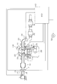
- FIG. 1 is a configuration diagram of an engine system
- FIG. 2 is a diagram showing a state of unvaporized fuel in a cylinder
- FIG. 3 is a diagram for explaining the calculation of the amount of unvaporized fuel generated
- FIG. 4 is a diagram illustrating the first control and the second control
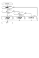
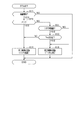
- FIG. 5 is a flowchart showing a procedure of engine start control
- FIG. 6 is a timing chart for explaining the transition of the operating state when the engine is started
- FIG. 7 is a diagram illustrating the second control according to the modification
- FIG. 8 is a timing chart showing the transition of the operating state of the engine according to the second embodiment
- FIG. 9 is a flowchart showing a procedure of engine start control
- FIG. 10 is a timing chart for explaining changes in engine rotation speed
- FIG. 11 is a flowchart showing a procedure of engine start control according to the third embodiment.
- the engine control system includes an engine mounted on a vehicle as an internal combustion engine, and controls the operation of this engine.
- the engine 10 shown in FIG. 1 is a cylinder injection 4-cycle gasoline engine. Specifically, the engine 10 is a 4-cylinder engine, and the cylinder block 11A is provided with four cylinders 21. In FIG. 1, only one cylinder 21 is shown and the other cylinders are omitted. A piston 35 is arranged in the cylinder 21 so as to be able to reciprocate. The reciprocating motion of the piston 35 causes the crankshaft 28 (output shaft) provided in the cylinder block 11A to rotate.
- the space defined by the inner wall of the cylinder 21 and the upper surface (top) of the piston 35 is referred to as a cylinder.
- the engine 10 is provided with an intake passage 12 that communicates with an intake port and through which intake air taken into the cylinder flows, and an exhaust passage 23 that communicates with an exhaust port and through which exhaust gas exhausted from the cylinder 21 flows.
- the intake port and the exhaust port are provided with an intake valve 31 and an exhaust valve 32 that open and close according to the rotation of a cam shaft (not shown).
- the intake valve 31 and the exhaust valve 32 are respectively provided with variable valve operating devices 33 and 34 that can change the opening / closing timing of the intake valve 31 and the exhaust valve 32.
- the variable valve operating devices 33 and 34 adjust the relative rotational phase between the crankshaft 28 and each of the intake and exhaust camshafts, and the phase adjustment to the advance side and the retard side with respect to a predetermined reference position. It is possible.
- hydraulically driven or electrically operated variable valve operating devices may be used as the variable valve operating devices 33 and 34.
- the engine 30 is provided with an injector 30 as a fuel injection valve for each cylinder 21, and fuel is directly injected from the injector 30 into the cylinder.
- a fuel pressure sensor 37 that detects the pressure of the fuel supplied to the injector 30 (hereinafter referred to as fuel pressure) is provided in the flow path of the fuel flowing from the fuel container (not shown) to the injector 30.
- a spark plug 22 is attached to the cylinder head of the engine 10, and a high voltage is applied to the spark plug 22 at a desired ignition timing through an ignition coil or the like (not shown). By applying this high voltage, spark discharge is generated between the opposing electrodes of the spark plug 22 and the fuel in the cylinder is ignited.
- the engine 10 is provided with a crank angle sensor 29 that outputs a crank angle signal for each predetermined crank angle when the engine 10 is operating. From the crank angle signal from the crank angle sensor 29, the rotation speed of the crankshaft 28 can be detected as the engine rotation speed Ne.
- a water temperature sensor 38 that detects the water temperature of the cooling water is provided in the cylinder block 11A.
- the intake passage 12 is provided with an air flow meter 13 that detects the amount of air taken into the cylinder as an intake air amount Ga.
- a throttle valve 16 whose opening is adjusted by a throttle actuator 15 such as a DC motor is provided on the downstream side of the air flow meter 13.
- a surge tank 18 is provided downstream of the throttle valve 16 in the intake passage 12.
- the catalytic converters 25 and 26 are provided in the exhaust passage 23.
- the catalytic converters 25 and 26 are configured by a three-way catalyst including an exhaust purification catalyst, a gasoline particulate filter that removes PN in the exhaust, and a 4-way-GPF in which the GPF carries the catalyst.
- an A / F sensor 24 that detects the air-fuel ratio of the exhaust is provided on the upstream side of the catalytic converters 25 and 26.
- the engine control system has an ECU 40 as a control device.
- the ECU 40 includes a microcomputer including a CPU, ROM, RAM and the like.
- the microcomputer executes various control programs stored in the ROM to control the fuel injection amount Q of the injector 30 and control the opening / closing timing of the intake valve 31 and the exhaust valve 32 in accordance with the engine operating state.
- the ignition timing of the spark plug 22 is controlled.
- the ECU 40 calculates the fuel injection amount Q according to the intake air amount Ga detected by the air flow meter 13 and the engine rotation speed Ne, and causes the injector 30 to inject fuel based on the fuel injection amount Q.
- the ECU 40 performs ISS restart control associated with satisfaction of restart conditions as the engine 10 start control.
- the ISS restart control automatically stops the engine 10 when a predetermined automatic stop condition is satisfied, and restarts the engine 10 by the starter 50 as a starter when the predetermined restart condition is satisfied under the automatic stop condition. is there.
- the ECU 40 corresponds to a restart control unit.
- HC and PM in the exhaust gas are likely to increase.
- the catalysts included in the catalytic converters 25 and 26 are not activated, and even if the exhaust gas passes through the catalytic converters 25 and 26, HC and PM are not sufficiently purified, and thus in the atmosphere. There is a concern that it will be released into the.
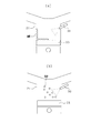
- FIG. 2 is a diagram illustrating the state of unvaporized fuel in the cylinder 21.
- FIG. 2A shows a state in which a fuel wet occurs in the cylinder 21.
- the fuel wet state is a state in which a large amount of fuel adheres to the inner wall surface and the upper portion of the piston 35 in the form of a liquid film in the cylinder.
- FIG. 2B shows a floating droplet state in which a large amount of fuel is in the form of a floating droplet in the cylinder.
- Floating droplet fuel is fuel that floats as droplets in the air-fuel mixture in the cylinder. In any of the states, the combustion of the air-fuel mixture in the cylinder is deteriorated, which becomes a factor to increase HC and PM in the exhaust gas.
- the state in which both the fuel amount of the fuel wet and the fuel amount in the form of floating droplets are small in the cylinder is defined as the normal state in which the wet concern state and the floating droplet state may not be taken into consideration. There is. It should be noted that when the fuel amount in the fuel wet is large and the fuel amount in the form of floating droplets is large, it is defined as a wet concern state.
- the ECU 40 determines whether the inside of the cylinder is in a wet concern state or the inside of the cylinder is in a floating droplet state when the engine 10 is started.
- the ECU 40 calculates an unvaporized fuel amount WE, which is an index value indicating the amount of unvaporized fuel generated in the cylinder, and based on the unvaporized fuel amount WE, whether the inside of the cylinder is in a wet concern state, or It is determined whether it is in a floating droplet state.
- the unvaporized fuel amount WE is calculated using at least one of the cooling water temperature Tw indicating the temperature of the cooling water detected by the water temperature sensor 38, the fuel injection amount Q, and the fuel pressure Pf detected by the fuel pressure sensor 37. calculate.
- the ECU 40 corresponds to a wet amount calculation unit.
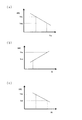
- FIG. 3A is a diagram for explaining calculation of the unvaporized fuel amount WE using the cooling water temperature Tw, where the horizontal axis represents the cooling water temperature Tw and the vertical axis represents the unvaporized fuel amount WE.
- the lower the cooling water temperature Tw the less likely the fuel is vaporized in the cylinder. Therefore, the unvaporized fuel amount WE is set to a larger value as the cooling water temperature Tw is lower.
- the unvaporized fuel amount WE is larger than the first temperature determination value THa, it is determined that the inside of the cylinder is in a wet concern state.
- the second temperature determination value THb is a value smaller than the first temperature determination value THa.
- the unvaporized fuel amount WE is equal to or lower than the second temperature determination value THb, it is determined that the inside of the cylinder is in the normal state.
- FIG. 3B is a diagram for explaining calculation of the unvaporized fuel amount WE using the fuel injection amount Q, in which the horizontal axis represents the fuel injection amount Q and the vertical axis represents the unvaporized fuel amount WE.
- the horizontal axis represents the fuel injection amount Q
- the vertical axis represents the unvaporized fuel amount WE.
- the second injection amount determination value THd is a value smaller than the first injection amount determination value THc.
- the unvaporized fuel amount WE is equal to or less than the second injection amount determination value THd, it is determined that the inside of the cylinder is in the normal state.
- FIG. 3C is a diagram for explaining calculation of the unvaporized fuel amount WE using the fuel pressure Pf, where the horizontal axis represents the fuel pressure Pf and the vertical axis represents the unvaporized fuel amount WE.
- the unvaporized fuel amount WE is larger than the first fuel pressure determination value THe, it is determined that the inside of the cylinder is in a wet concern state.
- the unvaporized fuel amount WE When the unvaporized fuel amount WE is equal to or less than the first fuel pressure determination value THe and is larger than the second fuel pressure determination value THf, it is determined that the inside of the cylinder is in a floating droplet state.
- the second fuel pressure determination value THf is smaller than the first fuel pressure determination value THe.
- the unvaporized fuel amount WE When the unvaporized fuel amount WE is equal to or less than the second fuel pressure determination value THf, it is determined that the inside of the cylinder is in the normal state.
- the ECU 40 corresponds to the determination unit.
- the unvaporized fuel amount WE shown in FIGS. 3 (a) to 3 (c) is individually used to determine the in-cylinder state, and instead of the sum of the unvaporized fuel amounts WE, the cylinder is determined. It is also possible to determine the internal state. In this case, each unvaporized fuel amount WE calculated from the cooling water temperature Tw, the fuel injection amount Q, and the fuel pressure Pf may be weighted. Further, the injection timing of the injector 30 or the engine rotation speed Ne may be used as the parameter for calculating the unvaporized fuel amount WE.
- FIG. 4 shows the changes in the valve opening amount IN of the intake valve 31 and the valve opening amount EX of the exhaust valve 32, the vertical axis shows the valve opening amount, and the horizontal axis shows the time transition.
- the opening timing A1 of the intake valve 31 is top dead as shown in FIG. It is set on the advance side from the point (hereinafter referred to as TDC), and the closing timing A2 is set on the retard side from the bottom dead center (hereinafter referred to as BDC). Further, in the normal state, in the present embodiment, the opening timing B1 of the exhaust valve 32 is set to the retard side of BDC and the closing timing B2 is set to the advance side of TDC.
- normal control of the opening / closing timing of the intake valve 31 and the exhaust valve 32 that is performed in the normal state is referred to as normal control.
- the ECU 40 determines that the inside of the cylinder is in a wet concern state, the ECU 40 controls the opening / closing timing of the intake valve 31 or the exhaust valve 32 by the variable valve operating devices 33 and 34 to reduce the intake air amount Ga. Take control.
- the ECU 40 corresponds to the first controller.
- the variable valve operating device 33 delays the closing timing A2 of the intake valve 31 so as to be farther from BDC than the closing timing A2 of the normal control. Slow closing control is performed. As a result, the intake air amount Ga filled in the cylinder in the intake stroke is lower than that in the case where the first control is not performed, and the fuel injection amount Q calculated using the intake air amount Ga is reduced. As the first control, the variable valve operating device 33 may be subjected to early closing control for advancing the closing timing A2 of the intake valve 31 so as to be farther from BDC than the closing timing A2 of the normal control. ..
- the ECU 40 executes the second control for raising the in-cylinder temperature as the control of the opening / closing timing of the intake / exhaust valves 31, 32 by the variable valve operating devices 33, 34.
- the ECU 40 corresponds to the second control unit.
- the ECU 40 controls the variable valve operating device 33 so that the closing timing A2 of the intake valve 31 is closer to BDC than the closing timing A2 of the normal control. Change the opening / closing timing.
- the closing timing A2 of the intake valve 31 is advanced so as to come closer to BDC than the closing timing A2 of the normal control.
- step S11 it is determined whether or not it is the starting period from the start of the engine 10 until a predetermined period elapses. Specifically, it is determined whether or not it is a period from when the starter 50 starts cranking when the engine 10 is turned on to when warm-up of the catalytic converters 25 and 26 ends. For example, whether or not the catalytic converters 25 and 26 have been warmed up may be determined by determining whether or not a predetermined time has elapsed from the start of starting the engine 10.
- step S12 the unvaporized fuel amount WE is calculated as shown in FIGS. 3 (a) to 3 (c).
- step S13 it is determined using the unvaporized fuel amount WE calculated in step S13 whether or not the inside of the cylinder is in a wet concern state.
- step S14 If it is determined that the inside of the cylinder is in a wet concern state, the process proceeds to step S14 and the first control is performed.
- the closing timing A2 of the intake valve 31 is retarded from BDC by the variable valve operating devices 33, 34 from the closing timing A2 in the normal control, and the intake air amount Ga decreases.
- the fuel injection amount Q is reduced and the fuel wet inside the cylinder is reduced.
- step S15 it is determined using the unvaporized fuel amount WE calculated in step S12 whether or not the inside of the cylinder is in a floating droplet state.
- step S16 it is determined using the unvaporized fuel amount WE calculated in step S12 whether or not the inside of the cylinder is in a floating droplet state.
- step S16 the second control is executed.
- the closing timing A2 of the intake valve 31 is brought closer to BDC than the closing timing A2 of the normal control, and the actual compression ratio in the compression stroke of the engine 10 increases.
- the in-cylinder temperature Tc rises and the amount of floating droplets in the cylinder decreases.
- the first determination of the wet concern state or the floating droplet state, and the first and second control depending on the determination result. are being implemented.
- the first and second controls can be started before the initial explosion of the engine 10 occurs, so that the effect of improving the wet concern state or the floating droplet state can be enhanced.
- step S15 If it is determined in step S15 that the inside of the cylinder is not in a floating droplet state, the process proceeds to step S17.
- step S17 since the inside of the cylinder is in the normal state, the normal control for fixing the opening / closing timing of the intake valve 31 is performed. Then, the process of FIG. 5 is once ended.
- the crankshaft 28 is cranked to provide an initial rotation during the period from time t1 to t2.
- the intake air amount Ga increases due to the flow of air in the intake passage 12 in accordance with the engine speed Ne (cranking speed).
- the intake air amount Ga shown by the broken line indicates the intake air amount Ga at the closing timing A2 of the intake valve 31 under normal control.
- the fuel injection amount Q calculated by the ECU 40 becomes smaller than the fuel injection amount Q in the normal control. Therefore, the amounts of HC and PN in the exhaust gas are reduced as compared with the case where the normal control is performed.
- the HC and PN emission amounts shown by the broken lines indicate the HC and PN emission amounts under normal control.
- the intake air amount Ga becomes the adjustment amount of the throttle valve 16, so that the fuel injection amount Q decreases and the unvaporized fuel amount WE decreases.
- the second control is performed in which the closing timing of the intake valve 31 is closer to BDC than the closing timing A2 in the normal control.
- the actual compression ratio increases in the compression stroke of the engine 10, and the in-cylinder temperature Tc rises.
- the amounts of HC and PN in the exhaust gas are reduced as compared with the case where normal control is performed.
- the intake air amount Ga increases as the actual compression ratio increases, the increase in the intake air amount Ga is suppressed by reducing the opening of the throttle valve 16.
- FIG. 6C for convenience of explanation, the intake air amount Ga in the normal control after time t3 and the intake air amount Ga in the second control are shown in a shifted state.
- the ECU 40 determines, when the engine 10 is started, whether the inside of the cylinder is in a wet concern state where there is a great concern about fuel wet, or whether the inside of the cylinder is in a floating droplet state in which there are many floating droplets of fuel. Then, when it is determined that there is a wet concern state, the first control for reducing the intake air amount Ga is executed as the control of the opening / closing timing by the variable valve operating devices 33, 34. As a result, the fuel injection amount Q is reduced, so that the wet fuel in the cylinder is reduced and HC and PN in the exhaust gas can be reduced.
- the second control for raising the in-cylinder temperature Tc is executed as the control of the opening / closing timing by the variable valve operating devices 33, 34.
- the fuel in the cylinder is easily vaporized, so that the amount of floating droplet fuel is reduced and HC and PN in the exhaust gas can be reduced.
- appropriate processing for reducing HC and PN can be performed according to the state of the fuel in the cylinder, so the effect of reducing HC and PN in the exhaust gas can be enhanced.
- the ECU 40 calculates the in-cylinder unvaporized fuel amount WE based on at least one of the temperature of the engine 10, the fuel injection amount Q, and the fuel pressure Pf. Then, based on the calculated unvaporized fuel amount WE, the wet concern state and the floating droplet state are determined. This makes it possible to easily determine the wet concern state and the floating droplet state according to the operating state of the engine 10.
- the ECU 40 may perform, as the second control, control for increasing the valve overlap period in which both the intake valve 31 and the exhaust valve 32 are opened.
- FIG. 7 shows the transition of the valve opening amount of the intake / exhaust valves 31 and 32 in the normal control by a broken line, and the transition of the valve opening amount after the opening / closing timing is changed by the second control.
- the ECU 40 advances the opening timing A1 of the intake valve 31 from TDC more than the opening timing A1 in the normal control, so that both the intake valve 31 and the exhaust valve 32 are moved.
- the valve overlap period OR1 to be opened is increased.
- internal EGR occurs in which the exhaust gas that has flowed out of the cylinder to the exhaust passage 23 flows into the cylinder again from the exhaust port.
- the in-cylinder temperature Tc rises, facilitating vaporization of the floating droplets in the cylinder.
- the ECU 40 retards the closing timing B2 of the exhaust valve 32 from TDC as compared with the closing timing B2 of the normal control, so that the intake valve 31 and the exhaust valve 32 are both controlled.
- the valve overlap period OR2 to be opened is increased.
- an internal EGR occurs in which the exhaust gas that has flowed out of the cylinder into the exhaust passage 23 returns to the cylinder again.
- the in-cylinder temperature Tc rises, facilitating vaporization of the floating droplets in the cylinder.
- the same effects as in the first embodiment can be obtained.
- the ECU 40 may determine whether the inside of the cylinder is in a wet concern state or the inside of the cylinder is in a floating droplet state after the engine 10 is stopped and before the engine 10 is started. In this case, for example, the ECU 40 calculates the unvaporized fuel amount WE using the cooling water temperature Tw or the fuel pressure Pf after the automatic stop by the ISS restart control, and uses the calculated unvaporized fuel amount WE to determine the cylinder interior. It is determined whether there is a wet concern state or a floating droplet state. Then, at the time of restarting the ISS, the first and second controls may be performed according to the already determined in-cylinder state. In the present embodiment, since the first and second controls can be performed at the same time when the engine 10 is started, the effect of improving the wet concern state or the floating droplet state can be enhanced.
- the pressure in the intake passage 12 is equivalent to the atmospheric pressure for a while after the start of the engine 10, the intake air amount Ga increases, and when the intake air amount Ga becomes the adjustment amount of the throttle valve 16 thereafter, the intake air amount Ga increases.
- the air amount Ga decreases.
- the pressure in the intake passage 12 is the atmospheric pressure Pa, and the pressure in the intake passage 12 decreases from the atmospheric pressure after the initial explosion occurs at t11. Therefore, in the present embodiment, the ECU 40 determines that the vehicle is in a wet state of concern when the first period P1 includes the start time when the intake air amount Ga increases and the second period following the first period P1. When it is P2, it is determined to be in a floating droplet state.
- step S11 When it is determined in step S11 that the engine 10 is in the starting period, the process proceeds to step S20, in which it is determined whether the period is the first period P1. Since the first control reduces the intake air amount Ga of the engine 10, it adversely affects the increase in the engine rotation speed Ne from the cranking rotation speed during the starting period of the engine 10. Therefore, it is desirable to limit the execution of the first control to the shortest possible period. Therefore, the period of one combustion cycle after the initial explosion is generated in the engine 10 after the initial rotation is applied to the engine 10 by the starter 50 is defined as the first period P1 in which the first control is performed.
- the period of the first combustion cycle after the end of cranking is a period of 720 ° CA from the initial explosion, and the combustion is performed once in each cylinder during this period. In this embodiment, the period of the first one combustion cycle after the end of cranking corresponds to the first period P1.
- step S11 If it is determined in step S11 that it is the first period P1, the process proceeds to step S14, and the first control for controlling the opening / closing timing of the intake valve 31 is performed. Therefore, in the present embodiment, the first control is always performed at the beginning of starting the engine 10.
- step S20 When it is determined in step S20 that it is not the first period P1, the process proceeds to step S21, and it is determined whether or not it is the period of the second combustion cycle after the initial explosion as the second period P2. If an affirmative decision is made in step S21, the operation proceeds to step S16 and the second control is carried out.
- step S21 If it is determined in step S21 that it is not the period of the second combustion cycle after the end of cranking, the process proceeds to step S17, and normal control that does not change the opening / closing timing of the intake valve 31 and the exhaust valve 32 is performed. Then, the processing in FIG. 9 is once ended.
- the ECU 40 determines that there is a wet concern state in the first period P1 including the start of the engine 10, and the floating droplet state in the second period following the first period P1. To determine. Thereby, since the first control and the second control are performed in order, the effect of improving the wet state in the cylinder can be enhanced.
- the ECU 40 determines the wet concern state by setting the first combustion cycle period after the initial explosion of the engine 10 after the initial rotation is given to the engine 10 by the starter 50 as the first period P1. Further, the floating droplet state is determined by setting the period following the period of one combustion cycle after the initial explosion of the engine 10 as the second period P2. As a result, the period in which the first control is performed can be limited to the period of one combustion cycle after the initial explosion of the engine 10, so that the engine rotation speed Ne does not rise to a predetermined value when the engine 10 is started. It is possible to shorten the time required for and to improve the startability of the engine 10.
- a procedure of starting control for the engine 10 according to the present embodiment will be described with reference to FIG. 11.
- the process shown in FIG. 11 is repeatedly executed by the ECU 40 at a predetermined cycle.
- step S11 When it is determined in step S11 that the engine 10 is in the starting period, the process proceeds to step S20, in which it is determined whether the period is the first period P1. Also in the present embodiment, the period of one combustion cycle after the end of cranking is set as the first period P1. In the case of the first period P1, the process proceeds to step S14, and the first control for controlling the opening / closing timing of the intake valve 31 is performed.
- step S31 it is determined whether the engine 10 is restarted by the ISS restart control.
- the process proceeds to step S16 and the second control is performed.
- the period following the period of one combustion cycle after the initial explosion occurs is defined as the second period P2.
- step S31 the operation proceeds to step S32 to decide whether or not the engine rotation speed Ne is stable.
- the difference between the engine rotation speed Ne (n-1) acquired in the previous calculation cycle and the engine rotation speed Ne (n) acquired in the current calculation cycle is calculated as the rotation speed difference ⁇ V. Then, when the calculated rotation speed difference ⁇ V is less than or equal to a predetermined speed difference determination value, it is determined that the engine rotation speed Ne is stable. On the other hand, when the rotation speed difference ⁇ V is larger than the speed determination value, it is determined that the engine rotation speed Ne is not stable.
- step S32 If the determination in step S32 is negative, the process proceeds to step S14 and the first control is performed. Therefore, the reduction of the intake air amount Ga of the engine 10 by the first control is continued. By continuing the reduction of the intake air amount Ga of the engine 10 by the first control, it is possible to suppress the increase of the engine rotation speed Ne, so that the stabilization of the engine rotation speed Ne can be accelerated.
- step S32 After that, every time the process of FIG. 11 is performed, it is determined in step S32 whether the engine rotation speed Ne is stable. Then, when it is determined in step S32 that the engine rotation speed Ne is stable, the process proceeds to step S16, and the second control is performed. Then, the processing of FIG. 11 is once ended.
- the ECU 40 sets the period until the rotational speed of the engine 10 becomes stable after the initial rotation is applied to the engine 10 by the starter 50 that rotates the crankshaft 28 of the engine 10 as the first period P1, and the wet concern state. And the period after the engine speed Ne has reached a stable state is set as the second period P2, and the floating droplet state is determined. As a result, it is possible to reduce the emission amount of HC and PN while suppressing the excessive fluctuation of the engine rotation speed Ne at the time of starting the engine 10.
- the ECU 40 determines the wet concern state by setting the period until the engine rotation speed Ne becomes the stable state as the first period P1, and stabilizes the engine rotation speed Ne. The period after the state is set as the second period P2, and the floating droplet state is determined.
- the period of one combustion cycle after the initial explosion occurs in the engine 10 is set to the first period P1 and the wet concern state is determined to cause the initial explosion. After that, the period following the period of one combustion cycle is set as the second period P2, and the floating droplet state is determined. As a result, it is possible to both suppress the driver from feeling uncomfortable due to excessive fluctuations in the engine rotation speed Ne during restart control and reduce the emissions of HC and PN.
- the ECU 40 determines the wet concern state by setting the period until the engine rotation speed Ne reaches the stable state as the first period P1,
- the floating droplet state may be determined by setting the period after the engine speed Ne has reached the stable state as the second period P2.
- step S31 in FIG. 11 may be deleted. Therefore, when making a negative determination in step S20, the process may proceed to step S32 and determine whether the engine rotation speed Ne is in a stable state.
- the engine 10 may be configured to include only the variable valve operating device 33 that controls only the opening / closing timing of the intake valve 31.
- the ECU 40 opens both the intake valve 31 and the exhaust valve 32 by controlling the closing timing of the intake valve 31 to approach BDC or advancing the opening timing A1 of the intake valve 31.
- the control for increasing the valve overlap period OR1 may be performed.
- the starting period during which the ECU 40 executes the first control and the second control is from the start of cranking by the starter 50 to the elapse of a predetermined period regardless of whether the catalytic converters 25 and 26 are active. May be In this case, the ECU 40 may determine in step S11 whether or not it is the starting period due to the lapse of time from the start of cranking by the starter 50.
- the ECU 40 may determine whether the inside of the cylinder is in a wet concern state or the inside of the cylinder is in a floating droplet state, on condition that the engine 10 is cold started.
- the engine 10 may be a port injection type internal combustion engine.
Landscapes
- Engineering & Computer Science (AREA)
- Chemical & Material Sciences (AREA)
- Combustion & Propulsion (AREA)
- Mechanical Engineering (AREA)
- General Engineering & Computer Science (AREA)
- Electrical Control Of Air Or Fuel Supplied To Internal-Combustion Engine (AREA)
- Output Control And Ontrol Of Special Type Engine (AREA)
- Control Of Vehicle Engines Or Engines For Specific Uses (AREA)
- Combined Controls Of Internal Combustion Engines (AREA)
Abstract
ECU(40)は、エンジン(10)の始動時において、筒内が燃料ウエットの懸念の大きいウエット懸念状態であるか、筒内が燃料の浮遊液滴の多い浮遊液滴状態であるかを判定する。ECU(40)は、ウエット懸念状態であると判定した場合に、可変動弁装置(33,34)による開閉タイミングの制御として、吸入空気量を低減させる第1制御を実施する。また、ECU(40)は、浮遊液滴状態であると判定した場合に、可変動弁装置(33,34)による開閉タイミングの制御として、筒内温度を上昇させる第2制御を実施する。
Description
本出願は、2018年11月13日に出願された日本出願番号2018-213189号に基づくもので、ここにその記載内容を援用する。
少なくとも吸気弁及び排気弁の開閉タイミングを可変とする可変動弁装置を備える内燃機関に適用される制御装置に関する。
特許文献1には、内燃機関の始動時における排気中のHC(炭化水素)の排出量を低減することを目的に、吸気弁又は排気弁の開閉タイミングを制御する制御装置が開示されている。特許文献1で開示された制御装置では、内燃機関の回転速度に基づいて、内燃機関の始動を検出した場合に、吸気弁と排気弁との開閉タイミングを制御している。
内燃機関の始動時において、筒内に未気化状態の燃料が多くなるほど、排気中のHCやPN(Particulate Number)が増加する。特許文献1では、筒内の燃料の状態を考慮することなく、内燃機関に対して開閉タイミングの制御が実施されるため、燃料の状態によっては、排出中のHCやPNを十分に低減できないことが懸念される。
本開示は上記課題に鑑みたものであり、筒内の燃料状態に合わせて、排気中のHCやPNの低減効果を高めることができる内燃機関の制御装置を提供することを目的とする。
上記課題を解決するために本開示では、筒内に燃料を噴射する燃料噴射弁と、吸気弁及び排気弁のうち少なくとも吸気弁の開閉タイミングを可変とする可変動弁装置と、を備える内燃機関に適用される制御装置に関するものである。制御装置は、前記内燃機関の吸入空気量に基づいて燃料噴射量を制御するとともに、前記内燃機関の運転状態に基づいて、前記可変動弁装置により前記吸気弁の開閉タイミングを制御する内燃機関の制御装置であって、前記内燃機関の始動時において、筒内が燃料ウエットの懸念の大きいウエット懸念状態であるか、筒内が燃料の浮遊液滴の多い浮遊液滴状態であるかを判定する判定部と、前記判定部により前記ウエット懸念状態であると判定された場合に、前記可変動弁装置による前記開閉タイミングの制御として、前記吸入空気量を低減させる第1制御を実施する第1制御部と、前記判定部により前記浮遊液滴状態であると判定された場合に、前記可変動弁装置による前記開閉タイミングの制御として、筒内温度を上昇させる第2制御を実施する第2制御部と、を備える。
筒内において燃料が十分に気化されていない状態として、燃料ウエットの懸念の大きいウエット懸念状態と、燃料の浮遊液滴の多い浮遊液滴状態とがあり、いずれも、HCやPNの排出量を増加させる要因となる。ここで、燃料ウエット懸念状態は、燃料噴射量が適正値よりも多いことが原因で生じ、浮遊液滴状態は、気筒の温度が低いことが原因で生じる。上記構成では、内燃機関の始動時において、筒内が燃料ウエットの懸念の大きいウエット懸念状態であるか、筒内が燃料の浮遊液滴の多い浮遊液滴状態であるかが判定される。そして、ウエット懸念状態であると判定された場合に、可変動弁装置による開閉タイミングの制御として吸入空気量を低減させる第1制御が実施される。これにより、燃料噴射量が低減するため、筒内のウエット状態が改善し、排気中のHC及びPNを低減することができる。一方で、浮遊液滴状態であると判定された場合に、可変動弁装置による開閉タイミングの制御として筒内温度を上昇させる第2制御が実施される。以上により、筒内の燃料が気化し易くなることで燃料の浮遊液滴が減少し、排気中のHCやPNを低減することができる。そのため、筒内の液体の状態に応じて、HCやPNを低減するための適正な開閉タイミングの制御を実施することができるため、排気中のHCやPNの低減効果を高めることができる。
本開示についての上記目的およびその他の目的、特徴や利点は、添付の図面を参照しながら下記の詳細な記述により、より明確になる。その図面は、
図1は、エンジンシステムの構成図であり、
図2は、気筒内の未気化状態の燃料の状態を示す図であり、
図3は、未気化状態の燃料の発生量の算出を説明する図であり、
図4は、第1制御及び第2制御を説明する図であり、
図5は、エンジンの始動制御の手順を示すフローチャートであり、
図6は、エンジンの始動時における運転状態の推移を説明するタイミングチャートであり、
図7は、変形例に係る第2制御を説明する図であり、
図8は、第2実施形態に係るエンジンの運転状態の推移を示すタイミングチャートであり、
図9は、エンジンの始動制御の手順を示すフローチャートであり、
図10は、エンジン回転速度の変化を説明するタイミングチャートであり、
図11は、第3実施形態に係るエンジンの始動制御の手順を示すフローチャートである。
(第1実施形態)
以下、本開示に係る内燃機関を具体化した一実施形態としてのエンジン制御システムを図面を用いて説明する。エンジン制御システムは、内燃機関としての車両に搭載されるエンジンを備え、このエンジンの運転を制御する。
以下、本開示に係る内燃機関を具体化した一実施形態としてのエンジン制御システムを図面を用いて説明する。エンジン制御システムは、内燃機関としての車両に搭載されるエンジンを備え、このエンジンの運転を制御する。
図1に示すエンジン10は、筒内噴射式の4サイクルガソリンエンジンである。具体的には、エンジン10は、4気筒エンジンであり、シリンダブロック11Aには、4つの気筒21が設けられている。なお、図1では、1つの気筒21のみを図示し、他の気筒については図示を省略している。気筒21には、ピストン35が往復運動可能に配置されている。ピストン35が往復運動することにより、シリンダブロック11A内に設けられたクランク軸28(出力軸)が回転する。本実施形態では、気筒21の内壁とピストン35の上面(頂部)とにより区画形成される空間を筒内と称す。
エンジン10は、吸気ポートと連通し、筒内に吸気される吸入空気が流れる吸気通路12と、排気ポートと連通し、気筒21から排気される排気が流れる排気通路23とを備えている。
吸気ポート及び排気ポートには、それぞれ図示しないカム軸の回転に応じて開閉動作する吸気弁31及び排気弁32が設けられている。吸気弁31及び排気弁32それぞれには、吸気弁31及び排気弁32の開閉タイミングを可変とする可変動弁装置33,34が設けられている。可変動弁装置33,34は、クランク軸28と吸排気の各カム軸との相対回転位相を調整するものであり、所定の基準位置に対して進角側及び遅角側への位相調整が可能となっている。可変動弁装置33,34としては、油圧駆動式又は電動式の可変動弁装置が用いられればよい。
エンジン10には気筒21ごとに燃料噴射弁としてのインジェクタ30が設けられており、筒内にはインジェクタ30から燃料が直接噴射される。不図示の燃料容器からインジェクタ30へ燃料が流れる流路には、インジェクタ30に供給される燃料の圧力(以下、燃圧と称す)を検知する燃圧センサ37が設けられている。
エンジン10のシリンダヘッドには点火プラグ22が取り付けられており、点火プラグ22には、図示しない点火コイル等を通じて、所望とする点火時期において高電圧が印加される。この高電圧の印加により、点火プラグ22の対向電極間に火花放電が発生し、筒内の燃料に着火する。
エンジン10には、エンジン10の運転時に所定クランク角ごとにクランク角信号を出力するクランク角度センサ29が設けられている。クランク角度センサ29からのクランク角信号により、クランク軸28の回転速度をエンジン回転速度Neとして検出できる。シリンダブロック11Aには、冷却水の水温を検出する水温センサ38が設けられている。
吸気通路12には筒内に吸気される空気量を吸入空気量Gaとして検出するエアフロメータ13が設けられている。吸気通路12において、エアフロメータ13よりも下流側には、DCモータ等のスロットルアクチュエータ15によって開度調節されるスロットル弁16が設けられている。吸気通路12において、スロットル弁16よりも下流側にはサージタンク18が設けられている。
排気通路23には、触媒コンバータ25,26が設けられている。触媒コンバータ25,26は、排気浄化触媒を備える三元触媒や、排気中のPNを除去するガソリン・パティキュレートフィルタや、GPFに触媒を担持した4way-GPF等により構成されている。
排気通路23において、触媒コンバータ25,26よりも上流側には、排気の空燃比を検知するA/Fセンサ24が設けられている。
エンジン制御システムは、制御装置としてのECU40を備えている。ECU40は、CPU、ROM、RAM等よりなるマイクロコンピュータを備えている。マイクロコンピュータがROMに記憶された各種の制御プログラムを実行することにより、エンジン運転状態に応じて、インジェクタ30の燃料噴射量Qの制御や、吸気弁31及び排気弁32の開閉タイミングの制御、更には点火プラグ22の点火時期の制御が実施される。
ECU40は、エアフロメータ13により検出された吸入空気量Gaや、エンジン回転速度Neに応じて燃料噴射量Qを算出し、その燃料噴射量Qに基づいて、インジェクタ30による燃料噴射を実施させる。
ECU40は、エンジン10の始動制御として、再始動条件の成立に伴うISS再始動制御を実施する。ISS再始動制御は、所定の自動停止条件の成立によりエンジン10を自動停止させ、その自動停止状態下において所定の再始動条件の成立により始動装置としてのスタータ50によりエンジン10を再始動させるものである。ECU40は、再始動制御部に相当する。
ここで、エンジン10の筒内に未気化状態の燃料量が多い場合、排気中のHCやPMが多くなり易い。特に、エンジン10の始動時は、触媒コンバータ25,26が備える触媒が活性化しておらず、排気が触媒コンバータ25,26を通過しても、HCやPMが十分に浄化されることなく大気中に放出されることが懸念される。
図2は、気筒21内の未気化燃料の状態を説明する図である。図2(a)は、気筒21内において燃料ウエットが生じた状態を示している。燃料ウエットとは、筒内に、内部壁面やピストン35の上部に液膜状に付着した燃料が多い状態である。また、図2(b)では、筒内に浮遊液滴状である燃料量が多い浮遊液滴状態を示している。浮遊液滴状の燃料は、筒内において、混合気中に液滴として浮遊する燃料である。いずれの状態においても、筒内での混合気の燃焼が悪化するため、排気中のHCやPMを増大させる要因となる。
本実施形態では、筒内において、燃料ウエットの燃料量と、浮遊液滴状の燃料量とが共に少ない状態を、ウエット懸念状態及び浮遊液滴状態を加味してなくともよい正常状態と定めている。なお、燃料ウエットの燃料量が多く、かつ浮遊液滴状の燃料量が多い場合は、ウエット懸念状態と定めている。
ECU40は、エンジン10の始動時において、筒内がウエット懸念状態であるか、又は筒内が浮遊液滴状態であるかを判定する。ECU40は、筒内における未気化状態の燃料の発生量を示す指標値である未気化燃料量WEを算出し、この未気化燃料量WEに基づいて、筒内がウエット懸念状態であるか、又は浮遊液滴状態であるかを判定する。具体的には、水温センサ38により検出された冷却水の温度を示す冷却水温Tw、燃料噴射量Q、及び燃圧センサ37により検出された燃圧Pfの少なくともいずれかを用いて未気化燃料量WEを算出する。ECU40は、ウエット量算出部に相当する。
図3(a)は、冷却水温Twを用いた未気化燃料量WEの算出を説明する図であり、横軸を冷却水温Twとし、縦軸を未気化燃料量WEとしている。冷却水温Twが低くなるほど、筒内において燃料が気化しにくくなる。そのため、冷却水温Twが低いほど、未気化燃料量WEを大きな値に定めている。本実施形態では、未気化燃料量WEが第1温度判定値THaよりも大きい場合、筒内がウエット懸念状態であると判定する。未気化燃料量WEが第1温度判定値THa以下であり、かつ第2温度判定値THbよりも大きい場合、筒内が浮遊液滴状態であると判定する。なお、第2温度判定値THbは、第1温度判定値THaよりも小さい値である。未気化燃料量WEが第2温度判定値THb以下である場合、筒内が正常状態であると判定する。
図3(b)は、燃料噴射量Qを用いた未気化燃料量WEの算出を説明する図であり、横軸を燃料噴射量Qとし、縦軸を未気化燃料量WEとしている。燃料噴射量Qが多くなるほど、筒内においてウエット状の燃料量が多くなり易い。そのため、燃料噴射量Qが大きな値であるほど、未気化燃料量WEを大きな値に定めている。本実施形態では、未気化燃料量WEが第1噴射量判定値THcよりも大きい場合、筒内がウエット懸念状態であると判定する。未気化燃料量WEが第1噴射量判定値THc以下であり、かつ第2噴射量判定値THdよりも大きい場合、筒内が浮遊液滴状態であると判定する。なお、第2噴射量判定値THdは、第1噴射量判定値THcよりも小さな値である。未気化燃料量WEが第2噴射量判定値THd以下である場合、筒内が正常状態であると判定する。
図3(c)は、燃圧Pfを用いた未気化燃料量WEの算出を説明する図であり、横軸を燃圧Pfとし、縦軸を未気化燃料量WEとしている。燃圧Pfが低くなるほど、燃料の気化が生じにくくなる。そのため、燃圧Pfが低いほど、未気化燃料量WEを大きな値に定めている。本実施形態では、未気化燃料量WEが第1燃圧判定値THeよりも大きい場合に、筒内がウエット懸念状態であると判定する。未気化燃料量WEが第1燃圧判定値THe以下であり、かつ第2燃圧判定値THfよりも大きい場合、筒内は浮遊液滴状態であると判定する。なお、第2燃圧判定値THfは、第1燃圧判定値THeよりも小さな値である。未気化燃料量WEが第2燃圧判定値THf以下である場合、筒内は正常状態であると判定する。ECU40は判定部に相当する。
なお、図3(a)~図3(c)に示す未気化燃料量WEを個別に用いて、筒内の状態を判定することに換えて、各未気化燃料量WEの和を用いて筒内の状態を判定するものであってもよい。この場合、冷却水温Tw、燃料噴射量Q、及び燃圧Pfにより算出した各未気化燃料量WEに重みを付与するものであってもよい。また、未気化燃料量WEを算出するパラメータとして、インジェクタ30の噴射タイミングや、エンジン回転速度Neを用いるものであってもよい。インジェクタ30の噴射タイミングが、BDCから遠いほど、筒内においてインジェクタ30の噴射口からピストン35までの距離が近くなるため、ピストン35の上面に付着する燃料が多くなり、未気化燃料量WEが大きくなる。エンジン回転速度Neが高いほど、筒内に噴射された燃料が蒸発するまでの猶予時間が短くなるため、未気化燃料量WEが大きくなる。
次に、図4を用いて、筒内をウエット懸念状態又は浮遊液滴状態と判定した場合の、吸排気弁31,32の開閉タイミングの制御を説明する。図4は、吸気弁31の開弁量IN及び排気弁32の開弁量EXの推移を示しており、縦軸は開弁量を示し、横軸は時間の推移を示している。
筒内が、ウエット懸念状態及び浮遊液滴状態を加味してなくともよい通常状態である場合、本実施形態では、図4(a)に示すように、吸気弁31の開き時期A1を上死点(以下、TDCと称す)よりも進角側に設定し、閉じ時期A2を下死点(以下、BDCと称する)よりも遅角側に設定する。また、通常状態である場合、本実施形態では、排気弁32の開き時期B1をBDCよりも遅角側に設定し、閉じ時期B2をTDCよりも進角側に設定している。以下、通常状態で実施される吸気弁31及び排気弁32の開閉タイミングの制御を通常制御と称す。
ウエット懸念状態は未気化燃料量WEが高い状態であるため、燃料噴射量Qを低減させることがウエット懸念状態の改善に効果がある。そこで、ECU40は、筒内がウエット懸念状態であると判定した場合に、可変動弁装置33,34による吸気弁31又は排気弁32の開閉タイミングの制御として、吸入空気量Gaを低減させる第1制御を実施する。ECU40は、第1制御部に相当する。
本実施形態では、図4(b)に示すように、第1制御として、可変動弁装置33に、吸気弁31の閉じ時期A2を通常制御での閉じ時期A2よりもBDCから遠ざけるように遅角させる遅閉じ制御を実施する。これにより、吸気行程において筒内に充填する吸入空気量Gaが第1制御を実施しない場合よりも低下し、吸入空気量Gaを用いて算出される燃料噴射量Qが低下する。なお、第1制御として、可変動弁装置33に吸気弁31の閉じ時期A2を通常制御での閉じ時期A2よりもBDCから遠ざけるように進角させる早閉じ制御を実施するものであってもよい。
混合気内に含まれる浮遊液滴は、筒内温度が高くなるほど気化が促進されるため、筒内温度を高くすることが浮遊液滴状態の改善に効果がある。そのため、ECU40は、可変動弁装置33,34による吸排気弁31,32の開閉タイミングの制御として、筒内温度を上昇させる第2制御を実施する。ECU40は、第2制御部に相当する。
図4(c)に示すように、ECU40は、第2制御として、可変動弁装置33に吸気弁31の閉じ時期A2を通常制御での閉じ時期A2よりもBDCに近づけるように吸気弁31の開閉タイミングを変更させる。本実施形態では、吸気弁31の閉じ時期A2が、通常制御での閉じ時期A2よりもBDCに近づけるように進角されている。これにより、エンジン10の圧縮行程において実圧縮比が増加することにより、筒内温度が上昇し、浮遊液滴を気化させ易くすることができる。
次に、図5を用いて、エンジン10に対する始動制御の手順を説明する。図5に示す処理は、ECU40により所定周期で繰り返し実施される。
ステップS11では、エンジン10の始動開始から所定期間が経過するまでの始動期間であるか否かを判定する。具体的には、エンジン10のIGオンに伴いスタータ50によりクランキングが開始されてから、触媒コンバータ25,26の暖機が終了するまでの期間であるか否かを判定する。例えば、触媒コンバータ25,26の暖機が終了したか否かの判定は、エンジン10の始動開始から予め定められた時間を経過したか否かを判定すればよい。
ステップS12では、図3(a)~(c)で示したように、未気化燃料量WEを算出する。ステップS13では、ステップS13で算出した未気化燃料量WEを用いて、筒内がウエット懸念状態であるか否かを判定する。
筒内がウエット懸念状態であると判定すると、ステップS14に進み、第1制御を実施する。第1制御により、可変動弁装置33,34により吸気弁31の閉じ時期A2が通常制御での閉じ時期A2よりもBDCから遅角され、吸入空気量Gaが低下する。これにより、燃料噴射量Qが減少し、筒内の燃料ウエットが低減される。
ステップS13において、筒内がウエット懸念状態でないと判定すると、ステップS15に進む。ステップS15では、ステップS12で算出した未気化燃料量WEを用いて、筒内が浮遊液滴状態であるか否かを判定する。ステップS15において、筒内が浮遊液滴状態であると判定すると、ステップS16に進む。
ステップS16では、第2制御を実施する。第2制御により、吸気弁31の閉じ時期A2が通常制御による閉じ時期A2よりもBDCに近づけられ、エンジン10の圧縮行程での実圧縮比が増加する。これにより、筒内温度Tcが上昇し、筒内の浮遊液滴の量が低下する。本実施形態では、エンジン10の始動開始から、スタータ50によるクランキングが終了するまでの期間に、最初のウエット懸念状態又は浮遊液滴状態の判定、及び判定結果に応じた第1,第2制御の実施までを実施している。これにより、エンジン10の初爆が生じるまでに第1,第2制御を開始することができるため、ウエット懸念状態又は浮遊液滴状態の改善効果を高めることができる。
ステップS15において、筒内が浮遊液滴状態でないと判定すると、ステップS17に進む。ステップS17に進む場合、筒内は通常状態であるため、吸気弁31の開閉タイミングを固定する通常制御を実施する。そして、図5の処理を一旦終了する。
次に、図6を用いて、エンジン10の始動開始時における運転状態の推移を説明する。
時刻t1で、運転者によるIGオン操作に伴い、ECU40に始動要求命令が入力すると、時刻t1-t2の期間では、スタータ50のクランキングによりクランク軸28に初期回転が付与される。エンジン回転数Ne(クランキング回転数)に応じて、吸気通路12内の空気の流れにより、吸入空気量Gaが増加する。
図6では、時刻t1-t2の期間において、筒内がウエット懸念状態であると判定されている。そのため、第1制御により、吸気弁31の閉じ時期A2が通常制御での閉じ時期A2よりもBDCから遅角されている。時刻t2では、エンジン10の初爆が起こり、エンジン回転速度Neが上昇する。
エンジン10の初爆後は、エンジン回転数Neがクランキング回転数よりも上昇し、吸入空気量Gaが上昇する。このとき、吸気弁31の閉じ時期A2がBDCよりも遅角されているため、吸入空気量Gaの増加が抑制される。図6(c)において、破線で示す吸入空気量Gaは、通常制御による吸気弁31の閉じ時期A2での吸入空気量Gaを示している。吸入空気量Gaの増加が抑制されることにより、ECU40が算出する燃料噴射量Qが、通常制御での燃料噴射量Qよりも少なくなる。そのため、排気中のHC,PNの量が通常制御を実施する場合よりも減少する。なお、図6(e)において、破線で示すHC及びPNの排出量は、通常制御でのHC及びPNの排出量を示している。
その後、吸入空気量Gaがスロットル弁16の調整量になることにより、燃料噴射量Qが少なくなり、未気化燃料量WEが減少する。本実施形態では、時刻t3以後では、筒内が浮遊液滴状態と判定されている。そのため、吸気弁31の閉じ時期が通常制御での閉じ時期A2よりもBDCに近づけられる第2制御が実施される。これにより、エンジン10の圧縮行程において実圧縮比が増加し、筒内温度Tcが上昇する。その結果、排気中のHC,PNの量が、通常制御を実施する場合よりも減少する。なお、実圧縮比の増加により、吸入空気量Gaが増加することが考えられるが、スロットル弁16の開度の減補正により吸入空気量Gaの増加は抑制される。なお、図6(c)では、説明の都合上、時刻t3以降の通常制御における吸入空気量Gaと、第2制御における吸入空気量Gaをずらした状態で図示している。
その後、筒内温度Tcが上昇することにより筒内の浮遊液滴の量が減少する。そして、時刻t4において、触媒コンバータ25,26の暖機が完了することにより、エンジン10に対する始動制御が終了する。
以上説明した本実施形態では以下の効果を奏することができる。
・ECU40は、エンジン10の始動時において、筒内が燃料ウエットの懸念の大きいウエット懸念状態であるか、又は筒内が燃料の浮遊液滴の多い浮遊液滴状態であるかを判定する。そして、ウエット懸念状態であると判定した場合に、可変動弁装置33,34による開閉タイミングの制御として吸入空気量Gaを低減させる第1制御を実施する。これにより、燃料噴射量Qが低減するため、筒内のウエット状の燃料が減少し、排気中のHC及びPNを低減することができる。また、浮遊液滴状態であると判定した場合に、可変動弁装置33,34による開閉タイミングの制御として筒内温度Tcを上昇させる第2制御を実施する。これにより、筒内の燃料が気化し易くなることにより浮遊液滴状の燃料が減少し、排気中のHCやPNを低減することができる。以上により、筒内の燃料の状態に応じて、HCやPNを低減するための適正な処理を実施することができるため、排気中のHCやPNの低減効果を高めることができる。
・ECU40は、エンジン10の温度、燃料噴射量Q、及び燃圧Pfの少なくともいずれかに基づいて、筒内の未気化燃料量WEを算出する。そして、算出した未気化燃料量WEに基づいて、ウエット懸念状態と、浮遊液滴状態とを判定する。これにより、エンジン10の運転状態に応じて、ウエット懸念状態と浮遊液滴状態とを容易に判定することができる。
(第1実施形態の変形例)
・ECU40は、第2制御として、吸気弁31及び排気弁32が共に開放されるバルブオーバーラップ期間を増加させる制御を実施してもよい。
・ECU40は、第2制御として、吸気弁31及び排気弁32が共に開放されるバルブオーバーラップ期間を増加させる制御を実施してもよい。
図7は、通常制御での吸排気弁31,32の開弁量の推移を破線で示し、第2制御により開閉タイミングが変更された後の開弁量の推移を実線で示している。図7(a)では、ECU40は、第2制御として、吸気弁31の開き時期A1を通常制御での開き時期A1よりもTDCから進角させることにより、吸気弁31と排気弁32とが共に開放されるバルブオーバーラップ期間OR1を増加させている。このバルブオーバーラップ期間OR1において、筒内から排気通路23に流出した排気が、排気ポートから再び筒内に流入する内部EGRが生じる。これにより、筒内温度Tcが上昇し、筒内の浮遊液滴を気化させ易くする。
図7(b)では、ECU40は、第2制御として、排気弁32の閉じ時期B2を通常制御での閉じ時期B2よりもTDCから遅角させることにより、吸気弁31と排気弁32とが共に開放されるバルブオーバーラップ期間OR2を増加させている。このバルブオーバーラップ期間OR2において、筒内から排気通路23に出た排気が再び筒内に戻る内部EGRが生じる。これにより、筒内温度Tcが上昇し、筒内の浮遊液滴を気化させ易くする。
以上説明した本実施形態においても、第1実施形態と同様の効果を奏することができる。
以上説明した本実施形態においても、第1実施形態と同様の効果を奏することができる。
・ECU40は、エンジン10の停止後であって、始動までの期間において、筒内がウエット懸念状態であるか、又は筒内が浮遊液滴状態であるかを判定してもよい。この場合、例えば、ECU40は、ISS再始動制御による自動停止後において、冷却水温Tw又は燃圧Pfを用いて未気化燃料量WEを算出し、かつ算出した未気化燃料量WEを用いて筒内がウエット懸念状態であるか、又は浮遊液滴状態であるかを判定する。そして、ISS再始動時において、すでに判定している筒内の状態に応じて、第1,第2制御を実施すればよい。本実施形態では、第1,第2制御をエンジン10の始動開始とともに行うことができるため、ウエット懸念状態又は浮遊液滴状態の改善効果を高めることができる。
(第2実施形態)
第2実施形態では、第1実施形態と異なる構成を主に説明する。なお、第1実施形態と同一の符号を付した構成は同一の構成を示し、その説明は繰り返さない。
第2実施形態では、第1実施形態と異なる構成を主に説明する。なお、第1実施形態と同一の符号を付した構成は同一の構成を示し、その説明は繰り返さない。
エンジン10の始動開始時からしばらくの間は、吸気通路12の圧力が大気圧相当であるため、吸入空気量Gaが多くなり、その後、吸入空気量Gaがスロットル弁16の調整量になると、吸入空気量Gaが減少する。図8では、エンジン10のクランキング期間P0では、吸気通路12の圧力が大気圧Paとなっており、t11で初爆が発生した後、吸気通路12の圧力が大気圧から減少している。そこで、本実施形態では、ECU40は、吸入空気量Gaが多くなる始動開始時を含む第1期間P1である場合に、ウエット懸念状態であると判定し、この第1期間P1に続く第2期間P2である場合に浮遊液滴状態であると判定する。
次に、図9を用いて、本実施形態に係るエンジン10に対する始動制御の手順を説明する。図9に示す処理は、ECU40により所定周期で繰り返し実施される。
ステップS11において、エンジン10の始動期間であることを判定すると、ステップS20に進み、第1期間P1であるか否かを判定する。第1制御は、エンジン10の吸入空気量Gaを低下させるため、エンジン10の始動期間において、エンジン回転速度Neにおけるクランキング回転速度からの上昇に悪影響を与える。そのため、第1制御の実施は、できるだけ短い期間に限定することが望ましい。そこで、スタータ50によりエンジン10に初期回転が付与された後、エンジン10に初爆が生じてから1燃焼サイクルの期間を、第1制御を実施する第1期間P1として定めている。クランキング終了後の最初の1燃焼サイクルの期間は、初爆から720°CAの期間であり、この期間において各気筒で1回ずつの燃焼が行われる。本実施形態では、クランキング終了後の最初の1燃焼サイクルの期間が第1期間P1に相当する。
ステップS11において、第1期間P1であると判定すると、ステップS14に進み、吸気弁31の開閉タイミングを制御する第1制御を実施する。そのため、本実施形態では、エンジン10の始動当初において、第1制御が必ず実施される。
ステップS20において、第1期間P1でないと判定すると、ステップS21に進み、第2期間P2として初爆後の2番目の燃焼サイクルの期間であるか否かを判定する。ステップS21を肯定判定すると、ステップS16に進み第2制御を実施する。
また、ステップS21において、クランキング終了後の2番目の燃焼サイクルの期間でないと判定すると、ステップS17に進み、吸気弁31及び排気弁32の開閉タイミングを変化させない通常制御を実施する。そして、図9の処理を一旦終了する。
以上説明した本実施形態では、以下の効果を奏することができる。
・ECU40は、エンジン10の始動開始時を含む第1期間P1である場合に、ウエット懸念状態であると判定し、第1期間P1に続く第2期間である場合に、浮遊液滴状態であると判定する。これにより、第1制御と第2制御とを順番に実施するため、筒内のウエット状態の改善効果を高めることができる。
・ECU40は、スタータ50によりエンジン10に初期回転が付与された後、エンジン10に初爆が生じてから最初の1燃焼サイクルの期間を第1期間P1として、ウエット懸念状態を判定する。また、エンジン10に初爆が生じてから1燃焼サイクルの期間に続く期間を第2期間P2として、浮遊液滴状態を判定する。これにより、第1制御を実施する期間を、エンジン10の初爆後の1燃焼サイクルの期間に限定することができるため、エンジン10の始動時において、エンジン回転速度Neが所定値まで上昇するのに要する時間を短くし、エンジン10の始動性を高めることができる。
(第3実施形態)
第3実施形態では、第1実施形態と異なる構成を主に説明する。なお、第1実施形態と同一の符号を付した構成は同一の構成を示し、その説明は繰り返さない。
第3実施形態では、第1実施形態と異なる構成を主に説明する。なお、第1実施形態と同一の符号を付した構成は同一の構成を示し、その説明は繰り返さない。
ISS再始動制御によりエンジン10を再始動させる場合、始動期間におけるエンジン10の振動をできるだけ小さくする必要がある。例えば、ISS再始動制御による再始動中に、エンジン回転速度Neが大きく変動すると、この変動を運転者が意識し易くなることが懸念される。図10では、初爆後のエンジン回転速度Neの上昇期間内において、時刻t21で第2制御により実圧縮比を増加させている。そのため、その後に、エンジン回転速度Neのオーバーシュートが生じている。
一方で、ISS再始動制御によりエンジン10が再始動する場合、既に触媒コンバータ25,26は暖機により活性化している可能性が高い。そこで、本実施形態では、ISS再始動制御によりエンジン10を再始動する場合は、エンジン回転速度Neの変動を抑制することを優先し、エンジン回転速度Neの安定を待った後(図10では、時刻t22)に第2制御を実施する。
図11を用いて、本実施形態に係るエンジン10に対する始動制御の手順を説明する。図11に示す処理は、ECU40により所定周期で繰り返し実施される。
ステップS11において、エンジン10の始動期間であることを判定すると、ステップS20に進み、第1期間P1であるか否かを判定する。本実施形態においても、クランキング終了後の1燃焼サイクルの期間を第1期間P1として定めている。第1期間P1である場合、ステップS14に進み、吸気弁31の開閉タイミングを制御する第1制御を実施する。
ステップS20において、第1期間P1でない場合、ステップS31に進み、ISS再始動制御によりエンジン10を再始動させているか否かを判定する。ISS再始動制御によりエンジン10を始動させていない場合は、ステップS16に進み、第2制御を実施する。この場合、初爆が生じてから1燃焼サイクルの期間に続く期間を第2期間P2として定めている。
ステップS31を肯定判定すると、ステップS32に進み、エンジン回転速度Neが安定しているか否かを判定する。本実施形態では、前回の演算周期で取得したエンジン回転速度Ne(n-1)と、今回の演算周期で取得したエンジン回転速度Ne(n)との差を、回転速度差ΔVとして演算する。そして、演算した回転速度差ΔVが所定の速度差判定値以下である場合に、エンジン回転速度Neが安定していると判定する。一方、回転速度差ΔVが速度判定値よりも大きい場合に、エンジン回転速度Neが安定していないと判定する。
ステップS32を否定判定すると、ステップS14に進み、第1制御を実施する。そのため、第1制御によるエンジン10の吸入空気量Gaの低減を継続する。第1制御によるエンジン10の吸入空気量Gaの低減を継続することにより、エンジン回転速度Neの上昇を抑制することができるため、エンジン回転速度Neの安定化を早めることができる。
その後、図11の処理を実施する毎に、ステップS32において、エンジン回転速度Neが安定しているか否かが判定される。そして、ステップS32において、エンジン回転速度Neが安定していると判定すると、ステップS16に進み、第2制御を実施する。そして、図11の処理を一旦終了する。
以上説明した本実施形態では、以下の効果を奏することができる。
・ECU40は、エンジン10のクランク軸28を回転させるスタータ50によりエンジン10に初期回転が付与された後、エンジン10の回転速度が安定状態になるまでの期間を第1期間P1として、ウエット懸念状態を判定し、エンジン回転速度Neが安定状態になった後の期間を第2期間P2として、浮遊液滴状態を判定する。これにより、エンジン10の始動時におけるエンジン回転速度Neの過度の変動を抑制しつつ、HC及びPNの排出量を削減することができる。
・ECU40は、ISS再始動制御によりエンジン10を再始動した場合は、エンジン回転速度Neが安定状態になるまでの期間を第1期間P1として、ウエット懸念状態を判定し、エンジン回転速度Neが安定状態になった後の期間を第2期間P2として、浮遊液滴状態を判定する。また、エンジン10の始動がISS再始動制御による再始動でない場合は、エンジン10に初爆が生じてから1燃焼サイクルの期間を第1期間P1として、ウエット懸念状態を判定し、初爆が生じてから1燃焼サイクルの期間に続く期間を第2期間P2として、浮遊液滴状態を判定する。これにより、再始動制御時のエンジン回転速度Neの過度の変動に起因して、運転者が違和感を覚えることの抑制と、HC及びPNの排出量の削減とを両立させることができる。
(第3実施形態の変形例)
ECU40は、ISS再始動制御の実施の有無に係わらず、エンジン10を再始動した場合は、エンジン回転速度Neが安定状態になるまでの期間を第1期間P1として、ウエット懸念状態を判定し、エンジン回転速度Neが安定状態になった後の期間を第2期間P2として、浮遊液滴状態を判定してもよい。この場合において、図11のステップS31を抹消すればよい。そのため、ステップS20を否定判定する場合は、ステップS32に進み、エンジン回転速度Neが安定状態であるか否かを判定すればよい。
ECU40は、ISS再始動制御の実施の有無に係わらず、エンジン10を再始動した場合は、エンジン回転速度Neが安定状態になるまでの期間を第1期間P1として、ウエット懸念状態を判定し、エンジン回転速度Neが安定状態になった後の期間を第2期間P2として、浮遊液滴状態を判定してもよい。この場合において、図11のステップS31を抹消すればよい。そのため、ステップS20を否定判定する場合は、ステップS32に進み、エンジン回転速度Neが安定状態であるか否かを判定すればよい。
(その他の実施形態)
・エンジン10は、吸気弁31の開閉タイミングのみを制御する可変動弁装置33のみを備える構成であってもよい。この場合、ECU40は、第2制御として、吸気弁31の閉じ時期をBDCに近づける制御、又は吸気弁31の開き時期A1を進角することにより、吸気弁31及び排気弁32が共に開放されるバルブオーバーラップ期間OR1を増加させる制御を実施すればよい。
・エンジン10は、吸気弁31の開閉タイミングのみを制御する可変動弁装置33のみを備える構成であってもよい。この場合、ECU40は、第2制御として、吸気弁31の閉じ時期をBDCに近づける制御、又は吸気弁31の開き時期A1を進角することにより、吸気弁31及び排気弁32が共に開放されるバルブオーバーラップ期間OR1を増加させる制御を実施すればよい。
・ECU40が第1制御と第2制御とを実施する始動期間は、スタータ50によりクランキングが開始されてから、触媒コンバータ25,26の活性の有無に依らず予め定められた期間が経過するまでであってもよい。この場合において、ECU40は、ステップS11で、スタータ50によるクランキングが開始されてからの時間の経過により始動期間であるか否かを判定すればよい。
・ECU40は、エンジン10が冷間始動していることを条件に、筒内がウエット懸念状態であるか、筒内が浮遊液滴状態であるかを判定してもよい。
・エンジン10は、ポート噴射式の内燃機関であってもよい。
本開示は、実施例に準拠して記述されたが、本開示は当該実施例や構造に限定されるものではないと理解される。本開示は、様々な変形例や均等範囲内の変形をも包含する。加えて、様々な組み合わせや形態、さらには、それらに一要素のみ、それ以上、あるいはそれ以下、を含む他の組み合わせや形態をも、本開示の範疇や思想範囲に入るものである。
Claims (7)
- 筒内に燃料を噴射する燃料噴射弁(30)と、
吸気弁(31)及び排気弁(32)のうち少なくとも吸気弁の開閉タイミングを可変とする可変動弁装置(33,34)と、
を備える内燃機関(10)に適用され、
前記内燃機関の吸入空気量に基づいて燃料噴射量を制御するとともに、前記内燃機関の運転状態に基づいて、前記可変動弁装置により前記吸気弁の開閉タイミングを制御する内燃機関の制御装置(40)であって、
前記内燃機関の始動時において、筒内が燃料ウエットの懸念の大きいウエット懸念状態であるか、又は筒内が燃料の浮遊液滴の多い浮遊液滴状態であるかを判定する判定部と、
前記判定部により前記ウエット懸念状態であると判定された場合に、前記可変動弁装置による前記開閉タイミングの制御として、前記吸入空気量を低減させる第1制御を実施する第1制御部と、
前記判定部により前記浮遊液滴状態であると判定された場合に、前記可変動弁装置による前記開閉タイミングの制御として、筒内温度を上昇させる第2制御を実施する第2制御部と、
を備える内燃機関の制御装置。 - 前記第1制御部は、前記第1制御として、前記吸気弁の閉じ時期を下死点から離す早閉じ又は遅閉じの制御を実施し、
前記第2制御部は、前記第2制御として、前記吸気弁の閉じ時期を下死点に近づける制御、又は前記吸気弁及び前記排気弁が共に開放されるバルブオーバーラップを増加させる制御を実施する請求項1に記載の内燃機関の制御装置。 - 前記内燃機関の温度、前記燃料噴射弁の燃料噴射量、及び前記燃料噴射弁に供給される燃料の燃圧の少なくともいずれかに基づいて、前記筒内の未気化状態の燃料の発生量を算出する算出部を備え、
前記判定部は、前記算出部により算出された前記筒内の未気化状態の燃料の発生量に基づいて、前記筒内が前記ウエット懸念状態であるか、又は前記筒内が前記浮遊液滴状態であるかを判定する請求項1又は2に記載の内燃機関の制御装置。 - 前記判定部は、前記内燃機関の始動開始から所定期間が経過するまでの期間において、前記内燃機関の始動開始時を含む第1期間である場合に、前記ウエット懸念状態であると判定し、前記第1期間に続く第2期間である場合に、前記浮遊液滴状態であると判定する請求項1又は2に記載の内燃機関の制御装置。
- 前記判定部は、
前記内燃機関の出力軸(28)を回転させる始動装置(50)により前記内燃機関に初期回転が付与された後、前記内燃機関に初爆が生じてから1燃焼サイクルの期間を、前記第1期間として、前記ウエット懸念状態を判定し、
前記初爆が生じてから1燃焼サイクルの期間に続く期間を前記第2期間として、前記浮遊液滴状態を判定する請求項4に記載の内燃機関の制御装置。 - 前記判定部は、
前記内燃機関の出力軸(28)を回転させる始動装置(50)により前記内燃機関に初期回転が付与された後、前記内燃機関の回転速度が安定状態になるまでの期間を、前記第1期間として、前記ウエット懸念状態を判定し、
前記内燃機関の回転速度が安定状態になった後の期間を前記第2期間として、前記浮遊液滴状態を判定する請求項4に記載の内燃機関の制御装置。 - 所定の自動停止条件が成立した場合に前記内燃機関を自動停止させ、その後に所定の再始動条件が成立した場合に、前記内燃機関を自動で始動させる再始動制御部を備え、
前記判定部は、
前記再始動制御部により前記内燃機関が始動された場合は、前記内燃機関の回転速度が前記安定状態になるまでの期間を前記第1期間として、前記ウエット懸念状態を判定するとともに、前記内燃機関の回転速度が前記安定状態になった後の期間を前記第2期間として、前記浮遊液滴状態を判定し、
前記内燃機関の始動が前記再始動制御部による始動でない場合は、前記内燃機関に初爆が生じてから1燃焼サイクルの期間を前記第1期間として、前記ウエット懸念状態を判定するとともに、前記初爆が生じてから前記1燃焼サイクルの期間に続く期間を前記第2期間として、前記浮遊液滴状態を判定する請求項6に記載の内燃機関の制御装置。
Priority Applications (2)
| Application Number | Priority Date | Filing Date | Title |
|---|---|---|---|
| DE112019005678.6T DE112019005678T5 (de) | 2018-11-13 | 2019-10-30 | Steuervorrichtung für Maschine mit interner Verbrennung |
| US17/315,848 US11313296B2 (en) | 2018-11-13 | 2021-05-10 | Control device for internal combustion engine |
Applications Claiming Priority (2)
| Application Number | Priority Date | Filing Date | Title |
|---|---|---|---|
| JP2018-213189 | 2018-11-13 | ||
| JP2018213189A JP6992730B2 (ja) | 2018-11-13 | 2018-11-13 | 内燃機関の制御装置 |
Related Child Applications (1)
| Application Number | Title | Priority Date | Filing Date |
|---|---|---|---|
| US17/315,848 Continuation US11313296B2 (en) | 2018-11-13 | 2021-05-10 | Control device for internal combustion engine |
Publications (1)
| Publication Number | Publication Date |
|---|---|
| WO2020100604A1 true WO2020100604A1 (ja) | 2020-05-22 |
Family
ID=70730478
Family Applications (1)
| Application Number | Title | Priority Date | Filing Date |
|---|---|---|---|
| PCT/JP2019/042679 WO2020100604A1 (ja) | 2018-11-13 | 2019-10-30 | 内燃機関の制御装置 |
Country Status (4)
| Country | Link |
|---|---|
| US (1) | US11313296B2 (ja) |
| JP (1) | JP6992730B2 (ja) |
| DE (1) | DE112019005678T5 (ja) |
| WO (1) | WO2020100604A1 (ja) |
Citations (3)
| Publication number | Priority date | Publication date | Assignee | Title |
|---|---|---|---|---|
| JP2002242712A (ja) * | 2001-02-20 | 2002-08-28 | Mitsubishi Motors Corp | 可変バルブタイミング機構付内燃機関 |
| JP2002327651A (ja) * | 2001-04-27 | 2002-11-15 | Toyota Motor Corp | 内燃機関の制御装置 |
| JP2005146917A (ja) * | 2003-11-12 | 2005-06-09 | Nissan Motor Co Ltd | エンジンの制御装置 |
Family Cites Families (9)
| Publication number | Priority date | Publication date | Assignee | Title |
|---|---|---|---|---|
| US5584277A (en) * | 1995-09-26 | 1996-12-17 | Chrysler Corporation | Fuel delivery system with wall wetting history and transient control |
| US5935188A (en) * | 1997-05-27 | 1999-08-10 | Chrysler Corporation | Determination of wall wetting for a port injected engine |
| JP3771101B2 (ja) | 2000-02-29 | 2006-04-26 | 株式会社日立製作所 | 内燃機関の制御装置 |
| US6874464B2 (en) * | 2003-08-01 | 2005-04-05 | Bombardier Recreational Products Inc. | System and method to detect and correct spark plug fouling in a marine engine |
| US7021289B2 (en) * | 2004-03-19 | 2006-04-04 | Ford Global Technology, Llc | Reducing engine emissions on an engine with electromechanical valves |
| JP4802968B2 (ja) * | 2006-10-24 | 2011-10-26 | 日産自動車株式会社 | エンジンの吸気バルブタイミング制御装置 |
| US9441570B2 (en) * | 2012-12-07 | 2016-09-13 | Ethanol Boosting Systems, Llc | Gasoline particulate reduction using optimized port and direct injection |
| WO2014089304A1 (en) * | 2012-12-07 | 2014-06-12 | Ethanol Boosting Systems, Llc | Port injection system for reduction of particulates from turbocharged direct injection gasoline engines |
| US10480439B2 (en) * | 2017-11-10 | 2019-11-19 | Ford Global Technologies, Llc | System and method for mitigating wet-fouling of spark plugs |
-
2018
- 2018-11-13 JP JP2018213189A patent/JP6992730B2/ja active Active
-
2019
- 2019-10-30 WO PCT/JP2019/042679 patent/WO2020100604A1/ja active Application Filing
- 2019-10-30 DE DE112019005678.6T patent/DE112019005678T5/de active Pending
-
2021
- 2021-05-10 US US17/315,848 patent/US11313296B2/en active Active
Patent Citations (3)
| Publication number | Priority date | Publication date | Assignee | Title |
|---|---|---|---|---|
| JP2002242712A (ja) * | 2001-02-20 | 2002-08-28 | Mitsubishi Motors Corp | 可変バルブタイミング機構付内燃機関 |
| JP2002327651A (ja) * | 2001-04-27 | 2002-11-15 | Toyota Motor Corp | 内燃機関の制御装置 |
| JP2005146917A (ja) * | 2003-11-12 | 2005-06-09 | Nissan Motor Co Ltd | エンジンの制御装置 |
Also Published As
| Publication number | Publication date |
|---|---|
| JP2020079580A (ja) | 2020-05-28 |
| JP6992730B2 (ja) | 2022-01-13 |
| DE112019005678T5 (de) | 2021-08-05 |
| US20210262406A1 (en) | 2021-08-26 |
| US11313296B2 (en) | 2022-04-26 |
Similar Documents
| Publication | Publication Date | Title |
|---|---|---|
| RU2690290C2 (ru) | Способ (варианты) и система управления холодным запуском двигателя | |
| JP5325756B2 (ja) | 内燃機関の燃料噴射制御装置 | |
| US8141533B2 (en) | Control apparatus and method for internal combustion engine | |
| JP5310733B2 (ja) | 内燃機関の制御装置 | |
| JP6350972B2 (ja) | エンジンの制御装置 | |
| US9903332B2 (en) | Control device of multi-cylinder internal combustion engine | |
| JP2012255366A (ja) | 内燃機関の制御装置及び制御方法 | |
| JP2018071485A (ja) | 内燃機関の制御装置 | |
| WO2016088649A1 (ja) | エンジンの制御装置 | |
| US9869260B2 (en) | Control device of multi-cylinder internal combustion engine | |
| JP3979376B2 (ja) | エンジンの制御装置 | |
| US20170089315A1 (en) | Engine control apparatus | |
| JP2009062863A (ja) | 内燃機関の制御装置 | |
| WO2020100604A1 (ja) | 内燃機関の制御装置 | |
| JP2007278073A (ja) | エンジンの制御方法及び制御装置 | |
| US20140261300A1 (en) | Fuel injection control apparatus for internal combustion engine | |
| JP4816591B2 (ja) | 内燃機関の制御装置 | |
| JP6288130B2 (ja) | エンジンの制御装置 | |
| JP4872654B2 (ja) | エンジンの制御方法及び制御装置 | |
| JP2016109015A (ja) | エンジンの制御装置 | |
| JP2008025536A (ja) | エンジンの制御方法及び制御装置 | |
| JP6914592B2 (ja) | 内燃機関の制御装置 | |
| JP2016070125A (ja) | 内燃機関の制御装置 | |
| JP2002180943A (ja) | 内燃機関の制御装置 | |
| JP6323798B2 (ja) | エンジンの制御装置 |
Legal Events
| Date | Code | Title | Description |
|---|---|---|---|
| 121 | Ep: the epo has been informed by wipo that ep was designated in this application |
Ref document number: 19885903 Country of ref document: EP Kind code of ref document: A1 |
|
| 122 | Ep: pct application non-entry in european phase |
Ref document number: 19885903 Country of ref document: EP Kind code of ref document: A1 |