WO2020100546A1 - 飲料供給装置 - Google Patents
飲料供給装置 Download PDFInfo
- Publication number
- WO2020100546A1 WO2020100546A1 PCT/JP2019/041652 JP2019041652W WO2020100546A1 WO 2020100546 A1 WO2020100546 A1 WO 2020100546A1 JP 2019041652 W JP2019041652 W JP 2019041652W WO 2020100546 A1 WO2020100546 A1 WO 2020100546A1
- Authority
- WO
- WIPO (PCT)
- Prior art keywords
- beverage
- opening
- main body
- body cabinet
- extraction unit
- Prior art date
- Legal status (The legal status is an assumption and is not a legal conclusion. Google has not performed a legal analysis and makes no representation as to the accuracy of the status listed.)
- Ceased
Links
Images




Classifications
-
- A—HUMAN NECESSITIES
- A47—FURNITURE; DOMESTIC ARTICLES OR APPLIANCES; COFFEE MILLS; SPICE MILLS; SUCTION CLEANERS IN GENERAL
- A47J—KITCHEN EQUIPMENT; COFFEE MILLS; SPICE MILLS; APPARATUS FOR MAKING BEVERAGES
- A47J31/00—Apparatus for making beverages
-
- A—HUMAN NECESSITIES
- A47—FURNITURE; DOMESTIC ARTICLES OR APPLIANCES; COFFEE MILLS; SPICE MILLS; SUCTION CLEANERS IN GENERAL
- A47J—KITCHEN EQUIPMENT; COFFEE MILLS; SPICE MILLS; APPARATUS FOR MAKING BEVERAGES
- A47J31/00—Apparatus for making beverages
- A47J31/44—Parts or details or accessories of beverage-making apparatus
-
- G—PHYSICS
- G07—CHECKING-DEVICES
- G07F—COIN-FREED OR LIKE APPARATUS
- G07F13/00—Coin-freed apparatus for controlling dispensing or fluids, semiliquids or granular material from reservoirs
-
- G—PHYSICS
- G07—CHECKING-DEVICES
- G07F—COIN-FREED OR LIKE APPARATUS
- G07F13/00—Coin-freed apparatus for controlling dispensing or fluids, semiliquids or granular material from reservoirs
- G07F13/06—Coin-freed apparatus for controlling dispensing or fluids, semiliquids or granular material from reservoirs with selective dispensing of different fluids or materials or mixtures thereof
Definitions
- the present invention relates to a beverage supply device.
- Patent Document 1 proposes a beverage supply device for supplying a beverage to a container.
- an extraction unit arranged inside a main body cabinet extracts a beverage from crushed beverage raw material and hot water, and supplies the extracted beverage to a container such as a cup.
- This extraction unit is composed of a cylinder, a lid and a filter block.
- the cylinder has a substantially cylindrical shape.
- the lid is provided in the upper region of the cylinder so as to be movable in a manner of approaching and separating from the cylinder in a manner of opening and closing an upper surface opening of the cylinder.
- the filter block is movably provided in the lower region of the cylinder so as to move closer to and away from the cylinder, and the lower surface opening of the cylinder is closed via the filter to extract the beverage and deliver the extracted beverage. It is a thing.
- the cleaning work such as once removing the cylinder or the like constituting the extraction unit from the main body cabinet for cleaning, or discarding the extraction residue generated by the extraction of the beverage by the extraction unit is regularly performed. It is generally done.
- the present invention has been made in view of the above circumstances, and an object thereof is to provide a beverage supply device that can simplify the cleaning operation of the extraction unit.
- the beverage supply device is capable of swinging to a side edge portion of the main body cabinet in a mode in which the main body cabinet has a rectangular parallelepiped shape having a front opening on the front surface and the front opening is opened and closed.
- An extraction unit for extracting a beverage from a raw material and hot water and supplying it to the container is installed on the other side edge portion inside the main body cabinet.
- a production unit that produces a beverage from a powdered raw material and hot water and supplies the beverage to the container is installed closer to the one side edge than the extraction unit inside the main body cabinet. It is characterized by being done.
- the present invention is, in the beverage supply device, arranged between the brewing unit and the brewing unit at a lower rear portion of the main body cabinet, and the brewing unit and the brewing unit are operated by an action of an exhaust fan incorporated therein.
- a fan box for sucking generated vapor and a fan filter detachably attached to the fan box through a filter opening formed in a front surface of the fan box are provided.
- the present invention is characterized in that, in the beverage supply device, the main body cabinet is provided with a nozzle for discharging the beverage extracted by the extraction unit and the beverage generated by the generation unit into the container.
- a replenishment opening is formed in an upper region of the brewing unit on the upper surface of the main body cabinet, and a replenishment door for opening and closing the replenishment opening is provided.
- the refill door is restricted from swinging in the opening direction when the front door closes the front opening, and swings in the opening direction when the front door opens the front opening. Is allowed to do.
- the extraction unit for crushing the beverage raw material, extracting the beverage from the crushed beverage raw material and the hot water, and supplying it to the container has a front door that opens and closes the front opening of the main body cabinet inside the main body cabinet. Is installed on one side edge of the main body cabinet that is swingably provided and on the other side opposite to the one side edge of the main body cabinet. Even when the components of the extraction unit are taken out through the front opening for cleaning or the like, there is no risk of interfering with the front door that opens the front opening. Therefore, there is an effect that the cleaning work of the extraction unit can be simplified.
- FIG. 1 is a perspective view showing an external configuration of a beverage supply device according to an embodiment of the present invention.
- FIG. 2 is an exploded perspective view in which some components of the beverage supply device according to the embodiment of the present invention are separated.
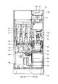
- FIG. 3 is a front view showing the internal structure of the main body cabinet shown in FIGS. 1 and 2.
- FIG. 4 is an enlarged perspective view showing a main part of the main body cabinet shown in FIG.
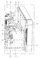
- FIG. 5 is a perspective view showing the internal structure of the main body cabinet shown in FIGS. 3 and 4.
- FIG. 6 is a sectional side view of the main body cabinet shown in FIG.
- FIG. 7 is a side view of the beverage supply device shown in FIG. 1, and schematically shows a part thereof.
- FIG. 8 is an enlarged perspective view showing a main part of the internal structure of the main body cabinet shown in FIG.
- FIG. 1 and 2 each show a beverage supply device according to an embodiment of the present invention
- FIG. 1 is a perspective view showing an external configuration
- the beverage supply device exemplified here is installed in a store such as a convenience store or a supermarket, and includes a device body 1.
- the device body 1 includes a body cabinet 10 and a front door 70. As shown in FIGS. 3 and 4, the main body cabinet 10 has a substantially rectangular parallelepiped shape having an opening (hereinafter, also referred to as a front opening) 10a on the front surface. Inside the main body cabinet 10, as shown in FIG. 5, a hot water tank 11, an extraction unit 20, a production unit 30, a beverage supply unit 40, and a fan box 50 are provided.
- the hot water tank 11 heats the supplied water and stores it as hot water.
- the hot water tank 11 is installed inside the main body cabinet 10 in the upper area on the left rear side.
- the extraction unit 20 is for extracting coffee from coffee beans as a beverage raw material and hot water delivered from the hot water tank 11, and includes an extraction raw material canister 21, a mill 22, a cylinder 23, and a filter block 24. Has been done.
- Such an extraction unit 20 is installed on the right front side inside the main body cabinet 10.
- the extraction material canister 21 stores coffee beans, which is a beverage material.
- the mill 22 is installed below the extraction material canister 21 and grinds the coffee beans discharged from the extraction material canister 21.
- the cylinder 23 is installed below the mill 22, and ground coffee beans are charged from the mill 22 and hot water is supplied from the hot water tank 11.
- the filter block 24 is installed below the cylinder 23 so as to be vertically movable so as to approach and separate from the cylinder 23, and has a filter such as a metal mesh.
- the coffee beans discharged from the extraction raw material canister 21 are crushed by the mill 22 to obtain ground coffee beans, and the ground coffee beans are put into the cylinder 23 and stored in the hot water tank 11.
- the ground coffee beans are steamed with the introduced ground coffee beans and hot water, and then stirred with hot water for cooking. Then, the ground coffee beans are filtered to extract the coffee in the filter block 24. Then, the coffee extracted in the filter block 24 is sent to the nozzle 60 described later.
- a storage box 25 is installed below the extraction unit 20.
- the storage box 25 is arranged in the lower region of the filter block 24 that constitutes the extraction unit 20.
- the storage box 25 stores a slag (not shown) generated by the brewing of the beverage in the brewing unit 20.
- the production unit 30 produces a beverage from the powder raw material which is the beverage raw material and the hot water delivered from the hot water tank 11, and includes a powder raw material canister 31 and a mixing ball 32.
- a generation unit 30 is installed inside the main body cabinet 10 on the front side of the hot water tank 11 and on the left side of the extraction unit 20 on the left side.
- a plurality of powder raw material canisters 31 (three in the illustrated example) are provided, and each is arranged side by side on the front side of the hot water tank 11.
- the powder raw material canisters 31 store different types of powder raw materials.
- a plurality of mixing balls 32 (three in the illustrated example) are provided. Such a mixing ball 32 stirs the powder material supplied from the corresponding powder material canister 31 and the hot water supplied from the hot water tank 11.
- the powder raw material discharged from one of the powder raw material canisters 31 is charged into the mixing ball 32, and the hot water stored in the hot water tank 11 is charged into the mixing ball 32.
- the mixing ball 32 the charged powder raw material and hot water are stirred and cooked, and the produced beverage is delivered to the nozzle 60.
- the beverage supply unit 40 is provided on the front side of the brewing unit 20 and the production unit 30, at the lower front portion of the main body cabinet 10, and has a stage 41.
- the stage 41 mounts a container C such as a cup (see FIG. 2), for example, and is provided with an arc-shaped stopper 42.
- a drain tray 43 for storing drainage of beverages and the like is installed.
- a nozzle 60 is provided above the stage 41.
- a plurality of nozzles 60 are provided, and in a state of being connected to the extraction unit 20 and each of the mixing balls 32, they are attached to the main body cabinet 10 via a support member 61. These nozzles 60 discharge the supplied beverage to the container C placed on the stage 41 and supply it.
- the fan box 50 is arranged between the extraction unit 20 and the generation unit 30 and in the lower rear part of the main body cabinet 10.
- the fan box 50 has a substantially rectangular parallelepiped shape and incorporates an exhaust fan (not shown). Then, the exhaust fan is driven to suck the steam generated in the extraction unit 20 and the generation unit 30 through the suction hose 51, and the sucked steam is discharged to the outside from the discharge part 12 formed in the lower rear surface of the main body cabinet 10. To be discharged to.
- a filter opening 52 (see FIG. 8) is formed on the front surface of the fan box 50, and a fan filter 53 is detachably attached through the filter opening 52.
- the front door 70 is a door body that opens and closes the front opening 10a of the main body cabinet 10, and at the left side edge portion on the front side of the main body cabinet 10, around the central axis of the shaft portion that extends along the up-down direction by the shaft support portion 70a. It is provided so that it can swing.
- the front door 70 has a display portion 71, an opening 72, and an opening / closing door 73.
- the display unit 71 is configured by, for example, a liquid crystal touch panel, displays various information, and can perform input operation such as touch operation.
- the display unit 71 gives a predetermined sales signal to a control unit (not shown) when an input operation such as a touch operation is performed.
- the opening 72 is provided on the lower side of the display unit 71 and exposes the beverage supply unit 40 toward the front.
- the opening / closing door 73 is made of a translucent material such as transparent resin, and has a sufficient size to cover the opening 72.
- the opening / closing door 73 has a left end pivotally supported by the front door 70 and is swingable along the front-rear direction. That is, the opening / closing door 73 is swingable along the front-rear direction in a manner of moving toward and away from the beverage supply unit 40, and closes the opening 72 when swinging backward in a manner of approaching the beverage supply unit 40.
- the opening 72 can be opened when swinging forward in a manner separated from the beverage supply unit 40.
- a replenishment opening 10b is formed in the right side portion of the upper surface of the main body cabinet 10, that is, in the upper region of the extraction material canister 21 of the extraction unit 20, and a replenishment door 13 for opening and closing the replenishment opening 10b is provided.
- the replenishment door 13 is provided with a handle 13a protruding forward.
- the handle 13a When the front door 70 closes the front opening 10a while the refill door 13 closes the refill opening 10b, the handle 13a is provided in a recess 74 provided in the front door 70 as shown in FIG. Has been inserted. Therefore, the replenishment door 13 is restricted from swinging in the opening direction when the front door 70 closes the front opening 10a, while it is held by the handle 13a when the front door 70 opens the front opening 10a. Is relatively disengaged from the concave portion 74, and thus is allowed to swing in the opening direction.
- the front door 70 is provided at the front left side edge portion of the main body cabinet 10 so as to be swingable around the central axis of the shaft portion.
- the extraction unit 20 is installed on the right front side inside the main body cabinet 10. That is, the front door 70 is swingably provided on one side edge of the main body cabinet 10 so as to open and close the front opening 10 a, and the extraction unit 20 is installed inside the main body cabinet 10 on the other side edge side. ing. Accordingly, even if the main body cabinet 10 is downsized due to the demand for downsizing of the entire apparatus, the front opening 10a is removed when the cylinder 23 of the extraction unit 20 is taken out through the front opening 10a for cleaning or the like. There is no risk of interfering with the front door 70 that opens.
- the cleaning operation of the extraction unit 20 can be simplified. Moreover, since the storage box 25 is also installed in the lower region of the extraction unit 20, there is no risk of interfering with the front door 70 that opens the front opening 10a when the storage box 25 is taken out for the disposal of the slag. The disposal work can be simplified.
- the fan box 50 is disposed between the extraction unit 20 and the production unit 30 in the lower rear part of the main body cabinet 10, and the filter formed on the front surface of the fan box 50. Since the fan filter 53 is detachably attached to the fan box 50 through the opening 52, when the front door 70 opens the front opening 10a, as shown in FIG. 8, it is only necessary to pull the fan filter 53 forward. Thus, the fan filter 53 can be easily taken out, and the fan filter 53 can be easily attached after cleaning. Therefore, the cleaning work of the fan filter 53 can be simplified.
- the nozzle 60 since the nozzle 60 is attached to the main body cabinet 10 via the support member 61, the length of the beverage supply hose 62 that supplies the beverage from the brewing unit 20 or the production unit 30 to the nozzle 60. Can be made large enough. That is, when the nozzle is installed on the front door 70, the front door 70 is opened and closed with respect to the main body cabinet 10, so that the length of the beverage supply hose 62 is sufficient considering the size of the movement. Although it is necessary to make the size large, since the nozzle 60 is provided in the main body cabinet 10, the distance between the nozzle 60 and the brewing unit 20, etc. is constant, and the length of the beverage supply hose 62 is consequently shortened. can do. Therefore, the storage space for the beverage supply hose 62 can be reduced.
- the replenishment opening 10b is provided on the upper surface of the main body cabinet 10, even if the main body cabinet 10 is downsized due to the request for downsizing of the entire device, the coffee bean Good replenishment can be performed. Moreover, the replenishment door 13 that opens and closes the replenishment opening 10b is restricted from swinging in the opening direction of the replenishment opening 10b when the front door 70 closes the front opening 10a. There is no risk that the foreign matter will be swung by force.
- the front door 70 is swingably provided on the left side edge of the main body cabinet 10, and the extraction unit 20 is provided on the right front side inside the main body cabinet 10.
- the front door is swingably provided at one side edge portion of the main body cabinet in a manner of opening and closing the front opening and the extraction unit is installed at the other side edge portion inside the main body cabinet, the direction thereof is It is not particularly limited.
Landscapes
- Engineering & Computer Science (AREA)
- Food Science & Technology (AREA)
- Physics & Mathematics (AREA)
- General Physics & Mathematics (AREA)
- Beverage Vending Machines With Cups, And Gas Or Electricity Vending Machines (AREA)
- Devices For Dispensing Beverages (AREA)
- Apparatus For Making Beverages (AREA)
Abstract
前面に前面開口10aを有する直方状の本体キャビネット10と、前面開口10aを開閉する態様で本体キャビネット10の一側縁部に揺動可能に設けられた前面扉70とを備え、所定個所に載置された容器Cに対して、本体キャビネット10の内部で調理した飲料を供給する飲料供給装置であって、飲料原料を粉砕し、粉砕した飲料原料と湯とから飲料を抽出して容器Cに供給する抽出ユニット20が、本体キャビネット10の内部における他側縁部側に設置されている。
Description
本発明は、飲料供給装置に関するものである。
従来、容器に対して飲料を供給する飲料供給装置が特許文献1に提案されている。かかる飲料供給装置は、本体キャビネットの内部に配設された抽出ユニットにて、粉砕された飲料原料と湯とから飲料を抽出し、抽出した飲料をカップ等の容器に供給するものである。
この抽出ユニットは、シリンダと、蓋体と、フィルタブロックとを備えて構成されている。シリンダは、略円筒状の形態を成している。蓋体は、シリンダの上方域において、該シリンダの上面開口を開閉する態様で該シリンダに近接離反する態様で移動可能に設けられている。フィルタブロックは、シリンダの下方域において、該シリンダに近接離反する態様で移動可能に設けられており、フィルタを介してシリンダの下面開口を閉成して飲料を抽出し、抽出した飲料を送出するものである。
ところで、上述した飲料供給装置においては、抽出ユニットを構成するシリンダ等を本体キャビネットから一旦取り外して洗浄したり、抽出ユニットによる飲料の抽出により生じた抽出滓を廃棄したりする清掃作業を定期的に行うのが一般的である。
その一方、上述した飲料供給装置においては、設置環境の自由度の向上等から、装置全体の小型化を図ることが求められている。
そのような小型化を図ると、抽出ユニットと、本体キャビネットの壁面とのスペースが小さくなり、上記清掃作業が煩雑なものとなる虞れがあった。
本発明は、上記実情に鑑みて、抽出ユニットの清掃作業を簡易なものとすることができる飲料供給装置を提供することを目的とする。
上記目的を達成するために、本発明に係る飲料供給装置は、前面に前面開口を有する直方状の本体キャビネットと、前記前面開口を開閉する態様で前記本体キャビネットの一側縁部に揺動可能に設けられた前面扉とを備え、所定個所に載置された容器に対して、前記本体キャビネットの内部で調理した飲料を供給する飲料供給装置であって、飲料原料を粉砕し、粉砕した飲料原料と湯とから飲料を抽出して前記容器に供給する抽出ユニットが、前記本体キャビネットの内部における他側縁部側に設置されたことを特徴とする。
また本発明は、上記飲料供給装置において、粉末原料と湯とから飲料を生成して前記容器に供給する生成ユニットが、前記本体キャビネットの内部における前記抽出ユニットよりも前記一側縁部側に設置されたことを特徴とする。
また本発明は、上記飲料供給装置において、前記抽出ユニットと前記生成ユニットとの間であって前記本体キャビネットの後方下部に配設され、内蔵する排気ファンの作用により該抽出ユニット及び該生成ユニットで生じた蒸気を吸引するファンボックスと、前記ファンボックスの前面に形成されたフィルタ開口を通じて、該ファンボックスに挿脱可能に装着されたファンフィルタとを備えたことを特徴とする。
また本発明は、上記飲料供給装置において、前記抽出ユニットで抽出された飲料、並びに前記生成ユニットで生成された飲料を前記容器に吐出するノズルが前記本体キャビネットに設けられたことを特徴とする。
また本発明は、上記飲料供給装置において、前記本体キャビネットの上面における前記抽出ユニットの上方域部分に補充開口が形成されるとともに、該補充開口を開閉するための補充扉が設けられており、前記補充扉は、前記前面扉が前記前面開口を閉塞する場合には、開く方向に揺動することが規制される一方、前記前面扉が前記前面開口を開放する場合には、開く方向に揺動することが許容されることを特徴とする。
本発明によれば、飲料原料を粉砕し、粉砕した飲料原料と湯とから飲料を抽出して容器に供給する抽出ユニットが、本体キャビネットの内部において、該本体キャビネットの前面開口を開閉する前面扉が揺動可能に設けられた該本体キャビネットの一側縁部と反対側となる他側縁部側に設置されているので、装置全体の小型化の要請から本体キャビネットの小型化が図られたとしても、抽出ユニットの構成要素を洗浄等のために前面開口を通じて取り出す際に、該前面開口を開放する前面扉と干渉する虞れがない。よって、抽出ユニットの清掃作業を簡易なものとすることができるという効果を奏する。
以下に添付図面を参照して、本発明に係る飲料供給装置の好適な実施の形態について詳細に説明する。
図1及び図2は、それぞれ本発明の実施の形態である飲料供給装置を示すものであり、図1は、外観構成を示す斜視図であり、図2は、一部の構成要素を分離させた分解斜視図である。ここで例示する飲料供給装置は、例えばコンビニエンスストアやスーパーマーケット等の店舗に設置されるものであり、装置本体1を備えている。
装置本体1は、本体キャビネット10及び前面扉70を備えている。本体キャビネット10は、図3及び図4に示すように、前面に開口(以下、前面開口ともいう)10aを有した略直方状の形態を成すものである。この本体キャビネット10の内部には、図5にも示すように、湯タンク11、抽出ユニット20、生成ユニット30、飲料供給部40及びファンボックス50が設けられている。
湯タンク11は、供給された水を加熱して湯として貯留するものである。この湯タンク11は、本体キャビネット10の内部において、左側後方の上方域に設置されている。
抽出ユニット20は、飲料原料であるコーヒー豆と、湯タンク11から送出される湯とからコーヒーを抽出するものであり、抽出原料キャニスタ21、ミル22、シリンダ23、フィルタブロック24とを備えて構成されている。このような抽出ユニット20は、本体キャビネット10の内部において、右側前方に設置されている。
抽出原料キャニスタ21は、飲料原料であるコーヒー豆を収納するものである。ミル22は、抽出原料キャニスタ21の下方に設置され、該抽出原料キャニスタ21から吐出されたコーヒー豆を粉砕するものである。
シリンダ23は、ミル22の下方に設置され、該ミル22からコーヒーの挽き豆が投入されるとともに、湯タンク11から湯が投入されるものである。
フィルタブロック24は、シリンダ23の下方において、該シリンダ23に近接離反するよう上下方向に移動可能に設置されており、例えば金属メッシュ等のフィルタを有している。
そのような抽出ユニット20では、ミル22で抽出原料キャニスタ21から吐出されたコーヒー豆を粉砕してコーヒー挽き豆を得、そのコーヒー挽き豆をシリンダ23に投入するとともに、湯タンク11に貯留された湯をシリンダ23に投入する。シリンダ23では、投入されたコーヒー挽き豆と湯とでコーヒー挽き豆を蒸らした後、湯で撹拌して調理する。その後、コーヒー挽き豆をろ過してフィルタブロック24内にコーヒーを抽出する。そして、フィルタブロック24内に抽出したコーヒーを後述するノズル60に送出する。
上記抽出ユニット20の下方には、収容箱25が設置されている。この収容箱25は、抽出ユニット20を構成するフィルタブロック24の下方域に配置されている。この収容箱25は、抽出ユニット20部での飲料の抽出により生じた抽出滓(図示せず)を収容するものである。
生成ユニット30は、飲料原料である粉末原料と、湯タンク11から送出される湯とから飲料を生成するものであり、粉末原料キャニスタ31及びミキシングボール32を備えて構成されている。このような生成ユニット30は、本体キャビネット10の内部において、湯タンク11の前方側であって抽出ユニット20の左側となる、左側前方に設置されている。
粉末原料キャニスタ31は、複数(図示の例では3つ)設けられ、それぞれが湯タンク11の前方側において左右に並ぶよう設置されている。これら粉末原料キャニスタ31は、それぞれ異なる種類の粉末原料を収納するものである。
ミキシングボール32は、複数(図示の例では3つ)設けられている。そのようなミキシングボール32は、対応する粉末原料キャニスタ31から投入された粉末原料と、湯タンク11から投入された湯とを撹拌するものである。
そのような生成ユニット30では、いずれかの粉末原料キャニスタ31から吐出された粉末原料をミキシングボール32に投入するとともに、湯タンク11に貯留された湯をミキシングボール32に投入する。ミキシングボール32では、投入された粉末原料と湯とを撹拌して調理し、生成した飲料をノズル60に送出する。
飲料供給部40は、抽出ユニット20や生成ユニット30の前方側であって、本体キャビネット10の前方下部に設けられており、ステージ41を有している。ステージ41は、例えばカップ等の容器C(図2参照)を載置させるものであり、円弧状のストッパ42が設けられている。かかるステージ41の下部には、図6に示すように、飲料等の排水を貯留する排水トレイ43が設置されている。
上記ステージ41の上方にはノズル60が設けられている。ノズル60は、複数設けられており、抽出ユニット20に接続されたものや各ミキシングボール32に接続された状態で、支持部材61を介して本体キャビネット10に取り付けられている。これらノズル60は、供給された飲料を、ステージ41に載置された容器Cに吐出して供給するものである。
ファンボックス50は、抽出ユニット20と生成ユニット30との間であって、本体キャビネット10の後方下部に配設されている。このファンボックス50は、略直方状の形態を成しており、図示せぬ排気ファンを内蔵している。そして、排気ファンが駆動することにより、吸引ホース51を通じて抽出ユニット20及び生成ユニット30で生じた蒸気を吸引するもので、吸引した蒸気を本体キャビネット10の後面下部に形成された排出部12より外部に排出するものである。
かかるファンボックス50の前面には、フィルタ開口52(図8参照)が形成されており、このフィルタ開口52を通じてファンフィルタ53が挿脱可能に装着されている。
前面扉70は、本体キャビネット10の前面開口10aを開閉する扉体であり、本体キャビネット10の前方側の左側縁部において、軸支部70aにより上下方向に沿って延在する軸部の中心軸回りに揺動可能に設けられている。
この前面扉70は、表示部71、開口部72及び開閉扉73を有している。表示部71は、例えば液晶タッチパネルにより構成されており、各種情報を表示するとともに、タッチ操作等の入力操作が可能である。この表示部71は、タッチ操作等の入力操作が行われた場合、所定の販売信号を図示せぬ制御部に与えるものである。
開口部72は、表示部71の下方側に設けられており、飲料供給部40を前方に向けて露出させるものである。開閉扉73は、例えば透明な樹脂等の透光性材料により構成されるものであり、開口部72を覆うのに十分な大きさを有している。この開閉扉73は、左側端部が前面扉70に軸支されており、前後方向に沿って揺動可能なものである。つまり開閉扉73は、飲料供給部40に対して近接離反する態様で前後方向に沿って揺動可能であり、飲料供給部40に近接する態様で後方に揺動する場合に開口部72を閉成させることが可能であり、飲料供給部40から離隔する態様で前方に揺動する場合に開口部72を開成させることが可能である。
ところで、本体キャビネット10の上面の右側部分、すなわち抽出ユニット20の抽出原料キャニスタ21の上方域には補充開口10bが形成されるとともに、該補充開口10bを開閉するための補充扉13が設けられている。かかる補充扉13には、前方に向けて突出する把手13aが設けられている。
把手13aは、補充扉13が補充開口10bを閉成している状態で、前面扉70が前面開口10aを閉塞する場合に、図7に示すように、前面扉70に設けられた凹部74に挿入されている。そのため、補充扉13は、前面扉70が前面開口10aを閉塞する場合には、開く方向に揺動することが規制される一方、前面扉70が前面開口10aを開放する場合には、把手13aが凹部74から相対的に離脱することで、開く方向に揺動することが許容されている。
以上説明したように、本発明の実施の形態である飲料供給装置においては、前面扉70が本体キャビネット10の前方側の左側縁部に軸部の中心軸回りに揺動可能に設けられており、抽出ユニット20が本体キャビネット10の内部において右側前方に設置されている。つまり、前面扉70が、前面開口10aを開閉する態様で本体キャビネット10の一側縁部に揺動可能に設けられ、抽出ユニット20が、本体キャビネット10の内部における他側縁部側に設置されている。これにより、装置全体の小型化の要請から本体キャビネット10の小型化が図られたとしても、抽出ユニット20のシリンダ23等を洗浄等のために前面開口10aを通じて取り出す際に、該前面開口10aを開放する前面扉70と干渉する虞れがない。
よって、上記飲料供給装置によれば、抽出ユニット20の清掃作業を簡易なものとすることができる。しかも、収容箱25も抽出ユニット20の下方域に設置されているので、抽出滓の廃棄のために収容箱25を取り出す際に、前面開口10aを開放する前面扉70と干渉する虞れがなく、廃棄作業を簡易なものとすることができる。
また上記飲料供給装置によれば、ファンボックス50が抽出ユニット20と生成ユニット30との間であって本体キャビネット10の後方下部に配設されており、このファンボックス50の前面に形成されたフィルタ開口52を通じて、ファンフィルタ53がファンボックス50に挿脱可能に装着されているので、前面扉70が前面開口10aを開放する場合に、図8に示すように、ファンフィルタ53を前方に引き出すだけでファンフィルタ53の取り出しを容易に行うことができ、清掃後のファンフィルタ53の装着も容易に行うことができる。よって、ファンフィルタ53の清掃作業を簡易なものとすることができる。
更に上記飲料供給装置によれば、ノズル60が支持部材61を介して本体キャビネット10に取り付けられているので、抽出ユニット20や生成ユニット30からノズル60へ飲料を供給する飲料供給ホース62の長さを必要十分な大きさにすることができる。つまり、ノズルを前面扉70に設置する場合には、前面扉70が本体キャビネット10に対して開閉移動するために、その移動分の大きさを考慮して飲料供給ホース62の長さを十分な大きさにする必要があるが、ノズル60が本体キャビネット10に設けられていることにより、ノズル60と抽出ユニット20等との距離が一定であり、飲料供給ホース62の長さを結果的に短くすることができる。そのため、飲料供給ホース62の収納スペースを小さくすることができる。
また更に上記飲料供給装置によれば、本体キャビネット10の上面に補充開口10bが設けられているので、装置全体の小型化の要請から本体キャビネット10の小型化が図られたとしても、コーヒー豆の補充を良好に行うことができる。しかも補充開口10bを開閉する補充扉13は、前面扉70が前面開口10aを閉塞する場合には、補充開口10bを開く方向に揺動することが規制されているので、悪戯等で補充扉13が無理に揺動させられて、異物等が入れられる虞れがない。
以上、本発明の好適な実施の形態について説明したが、本発明はこれに限定されるものではなく、種々の変更を行うことができる。
上述した実施の形態では、前面扉70が本体キャビネット10の左側縁部に揺動可能に設けられ、抽出ユニット20が本体キャビネット10の内部における右側前方に設けられていたが、本発明においては、前面扉が、前面開口を開閉する態様で本体キャビネットの一側縁部に揺動可能に設けられ、抽出ユニットが、本体キャビネットの内部における他側縁部側に設置されていれば、その方向は特に限定されるものではない。
1…装置本体、10…本体キャビネット、10a…前面開口、10b…補充開口、11…湯タンク、13…補充扉、13a…把手、20…抽出ユニット、21…抽出原料キャニスタ、22…ミル、23…シリンダ、24…フィルタブロック、25…収容箱、30…生成ユニット、31…粉末原料キャニスタ、32…ミキシングボール、40…飲料供給部、41…ステージ、42…ストッパ、43…排水トレイ、50…ファンボックス、52…フィルタ開口、53…ファンフィルタ、60…ノズル、70…前面扉、71…表示部、72…開口部、73…開閉扉、74…凹部、C…容器。
Claims (5)
- 前面に前面開口を有する直方状の本体キャビネットと、
前記前面開口を開閉する態様で前記本体キャビネットの一側縁部に揺動可能に設けられた前面扉と
を備え、所定個所に載置された容器に対して、前記本体キャビネットの内部で調理した飲料を供給する飲料供給装置であって、
飲料原料を粉砕し、粉砕した飲料原料と湯とから飲料を抽出して前記容器に供給する抽出ユニットが、前記本体キャビネットの内部における他側縁部側に設置されたことを特徴とする飲料供給装置。 - 粉末原料と湯とから飲料を生成して前記容器に供給する生成ユニットが、前記本体キャビネットの内部における前記抽出ユニットよりも前記一側縁部側に設置されたことを特徴とする請求項1に記載の飲料供給装置。
- 前記抽出ユニットと前記生成ユニットとの間であって前記本体キャビネットの後方下部に配設され、内蔵する排気ファンの作用により該抽出ユニット及び該生成ユニットで生じた蒸気を吸引するファンボックスと、
前記ファンボックスの前面に形成されたフィルタ開口を通じて、該ファンボックスに挿脱可能に装着されたファンフィルタと
を備えたことを特徴とする請求項2に記載の飲料供給装置。 - 前記抽出ユニットで抽出された飲料、並びに前記生成ユニットで生成された飲料を前記容器に吐出するノズルが前記本体キャビネットに設けられたことを特徴とする請求項2又は請求項3に記載の飲料供給装置。
- 前記本体キャビネットの上面における前記抽出ユニットの上方域部分に補充開口が形成されるとともに、該補充開口を開閉するための補充扉が設けられており、
前記補充扉は、前記前面扉が前記前面開口を閉塞する場合には、開く方向に揺動することが規制される一方、前記前面扉が前記前面開口を開放する場合には、開く方向に揺動することが許容されることを特徴とする請求項1~4のいずれか1つに記載の飲料供給装置。
Priority Applications (1)
| Application Number | Priority Date | Filing Date | Title |
|---|---|---|---|
| CN201980064249.XA CN112770654B (zh) | 2018-11-12 | 2019-10-24 | 饮料供给装置 |
Applications Claiming Priority (2)
| Application Number | Priority Date | Filing Date | Title |
|---|---|---|---|
| JP2018-212282 | 2018-11-12 | ||
| JP2018212282A JP7251109B2 (ja) | 2018-11-12 | 2018-11-12 | 飲料供給装置 |
Publications (1)
| Publication Number | Publication Date |
|---|---|
| WO2020100546A1 true WO2020100546A1 (ja) | 2020-05-22 |
Family
ID=70732074
Family Applications (1)
| Application Number | Title | Priority Date | Filing Date |
|---|---|---|---|
| PCT/JP2019/041652 Ceased WO2020100546A1 (ja) | 2018-11-12 | 2019-10-24 | 飲料供給装置 |
Country Status (3)
| Country | Link |
|---|---|
| JP (1) | JP7251109B2 (ja) |
| CN (1) | CN112770654B (ja) |
| WO (1) | WO2020100546A1 (ja) |
Citations (8)
| Publication number | Priority date | Publication date | Assignee | Title |
|---|---|---|---|---|
| JP2000014553A (ja) * | 1998-07-03 | 2000-01-18 | Hoshizaki Electric Co Ltd | 給茶機 |
| JP2006296663A (ja) * | 2005-04-19 | 2006-11-02 | Toshiba Electric Appliance Co Ltd | 飲料機器 |
| JP2007167300A (ja) * | 2005-12-21 | 2007-07-05 | Fuji Electric Retail Systems Co Ltd | 飲料抽出装置 |
| JP2009112628A (ja) * | 2007-11-08 | 2009-05-28 | Hoshizaki Electric Co Ltd | 飲料抽出装置 |
| JP2010108015A (ja) * | 2008-10-28 | 2010-05-13 | Fuji Electric Retail Systems Co Ltd | カップ式自動販売機 |
| JP2013508850A (ja) * | 2009-10-20 | 2013-03-07 | コーニンクレッカ フィリップス エレクトロニクス エヌ ヴィ | 二重機能自動販売機 |
| JP2014008292A (ja) * | 2012-06-29 | 2014-01-20 | Sanyo Product Co Ltd | 遊技機 |
| US20150027315A1 (en) * | 2012-02-21 | 2015-01-29 | Schaerer Ag | Beverage preparation module having additional modules for self-service beverage vending machines |
Family Cites Families (7)
| Publication number | Priority date | Publication date | Assignee | Title |
|---|---|---|---|---|
| JPH05274545A (ja) * | 1992-03-25 | 1993-10-22 | Fuji Electric Co Ltd | カップ式自動販売機の給湯装置 |
| US5353692A (en) * | 1993-09-29 | 1994-10-11 | Unidynamics Corporation | Hot beverage brewing apparatus |
| KR200455275Y1 (ko) * | 2010-03-18 | 2011-08-29 | 이성암 | 냉동고 도어 손잡이 |
| JP5765929B2 (ja) * | 2010-12-16 | 2015-08-19 | ホシザキ電機株式会社 | 飲料ディスペンサ |
| CN203493419U (zh) * | 2012-10-08 | 2014-03-26 | 房嵩阳 | 全自动智能遥控多功能豆浆机 |
| NL2015965B1 (nl) * | 2015-12-16 | 2016-09-08 | Etna Coffee Equipment B V | Inrichting voor het bereiden van een drank. |
| JP2017122966A (ja) * | 2016-01-05 | 2017-07-13 | 富士電機株式会社 | 自動販売機 |
-
2018
- 2018-11-12 JP JP2018212282A patent/JP7251109B2/ja active Active
-
2019
- 2019-10-24 WO PCT/JP2019/041652 patent/WO2020100546A1/ja not_active Ceased
- 2019-10-24 CN CN201980064249.XA patent/CN112770654B/zh active Active
Patent Citations (8)
| Publication number | Priority date | Publication date | Assignee | Title |
|---|---|---|---|---|
| JP2000014553A (ja) * | 1998-07-03 | 2000-01-18 | Hoshizaki Electric Co Ltd | 給茶機 |
| JP2006296663A (ja) * | 2005-04-19 | 2006-11-02 | Toshiba Electric Appliance Co Ltd | 飲料機器 |
| JP2007167300A (ja) * | 2005-12-21 | 2007-07-05 | Fuji Electric Retail Systems Co Ltd | 飲料抽出装置 |
| JP2009112628A (ja) * | 2007-11-08 | 2009-05-28 | Hoshizaki Electric Co Ltd | 飲料抽出装置 |
| JP2010108015A (ja) * | 2008-10-28 | 2010-05-13 | Fuji Electric Retail Systems Co Ltd | カップ式自動販売機 |
| JP2013508850A (ja) * | 2009-10-20 | 2013-03-07 | コーニンクレッカ フィリップス エレクトロニクス エヌ ヴィ | 二重機能自動販売機 |
| US20150027315A1 (en) * | 2012-02-21 | 2015-01-29 | Schaerer Ag | Beverage preparation module having additional modules for self-service beverage vending machines |
| JP2014008292A (ja) * | 2012-06-29 | 2014-01-20 | Sanyo Product Co Ltd | 遊技機 |
Also Published As
| Publication number | Publication date |
|---|---|
| CN112770654B (zh) | 2024-01-23 |
| JP2020080002A (ja) | 2020-05-28 |
| JP7251109B2 (ja) | 2023-04-04 |
| CN112770654A (zh) | 2021-05-07 |
Similar Documents
| Publication | Publication Date | Title |
|---|---|---|
| JP5450152B2 (ja) | 飲料製造装置 | |
| US20080178742A1 (en) | Built-In Coffee Machine And Related Activation Process | |
| JP5537987B2 (ja) | ミルクフォーマー及び飲料製造装置 | |
| JP2020090296A (ja) | 飲料供給装置 | |
| JP7251109B2 (ja) | 飲料供給装置 | |
| JP5282676B2 (ja) | カップ式飲料自動販売機 | |
| JP7443773B2 (ja) | 飲料供給装置 | |
| JP2011167396A (ja) | 飲料製造装置 | |
| WO2020116286A1 (ja) | 飲料供給装置 | |
| JP2020089472A (ja) | 飲料抽出装置 | |
| JP2011167397A (ja) | 飲料製造装置 | |
| JP7169631B2 (ja) | 飲料製造装置 | |
| JP2011167395A (ja) | 飲料製造装置 | |
| JP6635161B1 (ja) | 飲料供給装置 | |
| US20210393070A1 (en) | Systems of distribution of edible products with enhanced access dispositions and geometries | |
| JP7509325B1 (ja) | 飲料供給装置 | |
| JP2021013468A (ja) | 飲料製造装置 | |
| JP2020089468A (ja) | 飲料抽出装置 | |
| JP7338197B2 (ja) | 飲料抽出装置 | |
| JP2024165441A (ja) | 飲料供給装置 | |
| CN112584726B (zh) | 饮料供给装置 | |
| JP2020043935A (ja) | 飲料供給装置 | |
| US20210393073A1 (en) | Systems and processes of distribution of edible products with selective access dispositions | |
| JP2023028341A (ja) | 飲料供給装置 | |
| JP2021090686A (ja) | 飲料供給装置 |
Legal Events
| Date | Code | Title | Description |
|---|---|---|---|
| 121 | Ep: the epo has been informed by wipo that ep was designated in this application |
Ref document number: 19884409 Country of ref document: EP Kind code of ref document: A1 |
|
| NENP | Non-entry into the national phase |
Ref country code: DE |
|
| 122 | Ep: pct application non-entry in european phase |
Ref document number: 19884409 Country of ref document: EP Kind code of ref document: A1 |