WO2020095917A1 - 保護素子 - Google Patents
保護素子 Download PDFInfo
- Publication number
- WO2020095917A1 WO2020095917A1 PCT/JP2019/043373 JP2019043373W WO2020095917A1 WO 2020095917 A1 WO2020095917 A1 WO 2020095917A1 JP 2019043373 W JP2019043373 W JP 2019043373W WO 2020095917 A1 WO2020095917 A1 WO 2020095917A1
- Authority
- WO
- WIPO (PCT)
- Prior art keywords
- electrode
- fuse element
- element material
- fuse
- protection element
- Prior art date
- Legal status (The legal status is an assumption and is not a legal conclusion. Google has not performed a legal analysis and makes no representation as to the accuracy of the status listed.)
- Ceased
Links
Images










Classifications
-
- H—ELECTRICITY
- H01—ELECTRIC ELEMENTS
- H01H—ELECTRIC SWITCHES; RELAYS; SELECTORS; EMERGENCY PROTECTIVE DEVICES
- H01H85/00—Protective devices in which the current flows through a part of fusible material and this current is interrupted by displacement of the fusible material when this current becomes excessive
- H01H85/0039—Means for influencing the rupture process of the fusible element
- H01H85/0047—Heating means
- H01H85/0052—Fusible element and series heating means or series heat dams
-
- H—ELECTRICITY
- H01—ELECTRIC ELEMENTS
- H01H—ELECTRIC SWITCHES; RELAYS; SELECTORS; EMERGENCY PROTECTIVE DEVICES
- H01H85/00—Protective devices in which the current flows through a part of fusible material and this current is interrupted by displacement of the fusible material when this current becomes excessive
- H01H85/0039—Means for influencing the rupture process of the fusible element
-
- H—ELECTRICITY
- H01—ELECTRIC ELEMENTS
- H01H—ELECTRIC SWITCHES; RELAYS; SELECTORS; EMERGENCY PROTECTIVE DEVICES
- H01H85/00—Protective devices in which the current flows through a part of fusible material and this current is interrupted by displacement of the fusible material when this current becomes excessive
- H01H85/02—Details
- H01H85/04—Fuses, i.e. expendable parts of the protective device, e.g. cartridges
- H01H85/05—Component parts thereof
- H01H85/143—Electrical contacts; Fastening fusible members to such contacts
-
- H—ELECTRICITY
- H01—ELECTRIC ELEMENTS
- H01H—ELECTRIC SWITCHES; RELAYS; SELECTORS; EMERGENCY PROTECTIVE DEVICES
- H01H85/00—Protective devices in which the current flows through a part of fusible material and this current is interrupted by displacement of the fusible material when this current becomes excessive
- H01H85/02—Details
- H01H85/36—Means for applying mechanical tension to fusible member
-
- H—ELECTRICITY
- H01—ELECTRIC ELEMENTS
- H01H—ELECTRIC SWITCHES; RELAYS; SELECTORS; EMERGENCY PROTECTIVE DEVICES
- H01H85/00—Protective devices in which the current flows through a part of fusible material and this current is interrupted by displacement of the fusible material when this current becomes excessive
- H01H85/02—Details
- H01H85/04—Fuses, i.e. expendable parts of the protective device, e.g. cartridges
- H01H85/05—Component parts thereof
- H01H85/055—Fusible members
- H01H85/06—Fusible members characterised by the fusible material
-
- H—ELECTRICITY
- H01—ELECTRIC ELEMENTS
- H01H—ELECTRIC SWITCHES; RELAYS; SELECTORS; EMERGENCY PROTECTIVE DEVICES
- H01H85/00—Protective devices in which the current flows through a part of fusible material and this current is interrupted by displacement of the fusible material when this current becomes excessive
- H01H85/02—Details
- H01H85/04—Fuses, i.e. expendable parts of the protective device, e.g. cartridges
- H01H85/05—Component parts thereof
- H01H85/055—Fusible members
- H01H85/08—Fusible members characterised by the shape or form of the fusible member
-
- Y—GENERAL TAGGING OF NEW TECHNOLOGICAL DEVELOPMENTS; GENERAL TAGGING OF CROSS-SECTIONAL TECHNOLOGIES SPANNING OVER SEVERAL SECTIONS OF THE IPC; TECHNICAL SUBJECTS COVERED BY FORMER USPC CROSS-REFERENCE ART COLLECTIONS [XRACs] AND DIGESTS
- Y02—TECHNOLOGIES OR APPLICATIONS FOR MITIGATION OR ADAPTATION AGAINST CLIMATE CHANGE
- Y02E—REDUCTION OF GREENHOUSE GAS [GHG] EMISSIONS, RELATED TO ENERGY GENERATION, TRANSMISSION OR DISTRIBUTION
- Y02E60/00—Enabling technologies; Technologies with a potential or indirect contribution to GHG emissions mitigation
- Y02E60/10—Energy storage using batteries
Definitions
- the present invention relates to protection elements.
- the present application claims priority based on Japanese Patent Application No. 2018-209897 filed in Japan on Nov. 7, 2018, and the content thereof is incorporated herein.
- a protective element for an electric circuit
- a protective element fuse element including a fuse element that heats and blows to cut off a current path when a current exceeding a rating flows is used.
- the protective element for example, a holder fixed fuse in which a glass tube is filled with solder, a chip fuse in which an Ag electrode is printed on the surface of a ceramic substrate, a screwing in which a part of a copper electrode is thinned and incorporated in a plastic case, or Plug-in type protection elements are often used. Since such a protective element is difficult to be surface-mounted by reflow and the efficiency of component mounting is low, surface-mounting type protective elements have been developed in recent years (for example, refer to Patent Documents 1 and 2).
- the surface mount type protection element is used as a protection element for overcharging and overcurrent of a battery pack using a lithium ion secondary battery, for example.
- Lithium-ion secondary batteries are used in mobile devices such as laptop computers, mobile phones, and smartphones, and in recent years, they have also been adopted in electric tools, electric bicycles, electric motorcycles, electric vehicles, and the like. Therefore, a protection element for large current and high voltage is required.
- arc discharge may occur when the fuse element is blown.
- the fuse element may be melted over a wide area, and vaporized metal may be scattered.
- the scattered metal may form a new current path, or the scattered metal may adhere to the terminals, the surrounding electronic components, or the like. Therefore, the high-voltage protection element is provided with a measure that does not generate arc discharge or stops arc discharge.
- Arc discharge depends on electric field strength (voltage / distance), and arc discharge does not stop until the distance between contacts exceeds a certain distance. Therefore, a protection element of the type that uses a spring is one that quickly stops the arc discharge by rapidly separating the spring and the fuse element to a distance where the arc discharge cannot be maintained using the elastic restoring force of the spring. Is.
- the manufacturing process becomes complicated, it is difficult to downsize the protection element, and there is a concern that the fusing of the fuse element material due to the heat generation of the heating element in the protection element is hindered.
- the bonding strength between the fuse element and the spring is likely to decrease with time in the use environment, and there is a concern about long-term stability.
- the present invention has been made in view of the above problems, and provides a protection element capable of promptly preventing arc discharge at the time of overcurrent interruption by utilizing elastic restoring force of a spring while ensuring long-term stability.
- the purpose is to do.
- the present invention provides the following means in order to solve the above problems.
- a protection element is a fuse element arranged between a first electrode, a second electrode having a spring property, and the first electrode and the second electrode.
- the fuse element material is sandwiched and supported by the first electrode and the second electrode in a bent state.
- At least one of the first electrode and the second electrode and the fuse element material may be joined by solder. Good.
- each of the first electrode and the second electrode has a claw portion at one end thereof, and the fuse element material is It may be sandwiched and supported by the claw portion of the first electrode and the claw portion of the second electrode.
- each of the first electrode and the second electrode includes one or a plurality of the claw portions, and the fuse element material is the same as the first electrode.
- Three or more claws and claws of the second electrode may be alternately sandwiched and supported by being alternately arranged.
- At least a part of the claws of the claws included in the first electrode and the second electrode has tips of the fuse elements. It may be bent on the material side.
- the first electrode has a spring property and is in a state of being bent with the first electrode in a state of being bent. It may be sandwiched and supported by the second electrode.
- the fuse element material may be formed of a laminated body including a high melting point metal layer and a low melting point metal layer.
- the low melting point metal layer is made of Pb-free solder
- the high melting point metal layer is made of Ag or Cu or an alloy containing Ag or Cu as a main component. Good.
- each of the first electrode and the second electrode may be provided with an external terminal hole.
- a first terminal member is connected to the first electrode and a second terminal member is connected to the second electrode. It may have been done.
- a heating element for heating the fuse element material and a third electrode for energizing the heating element are further provided. May be.
- the heating element has one end connected to the third electrode and the other end of the fuse element material, the first electrode, and the second electrode. , May be connected to at least one.
- a third terminal member may be connected to the third electrode.
- a protection element capable of promptly preventing arc discharge when an overcurrent is interrupted by utilizing elastic restoring force of a spring while ensuring long-term stability.
- FIG. 1 is a schematic plan view of an example of the protection element according to the first embodiment.
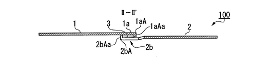
- 2 is a schematic sectional view of the protection element shown in FIG. 1 taken along the line II-II ′ in FIG.
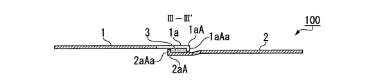
- FIG. 3 is a schematic sectional view of the protection element shown in FIG. 1 taken along the line III-III ′ in FIG.
- FIG. 4 is a schematic plan view of another example of the protection element according to the first embodiment.
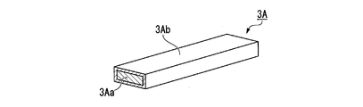
- FIG. 5 is a perspective view schematically showing an example of the structure of the fuse element material that can be used in the protection element according to the first embodiment.
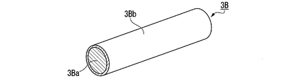
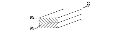
- FIG. 6 is a perspective view schematically showing another example of the structure of the fuse element material that can be used in the protection element according to the first embodiment.
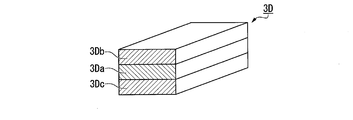
- FIG. 7 is a perspective view schematically showing still another example of the structure of the fuse element material that can be used for the protection element according to the first embodiment.
- FIG. 8 is a perspective view schematically showing still another example of the structure of the fuse element material that can be used in the protection element according to the first embodiment.
- FIG. 9 is a schematic plan view of an example of the protection element according to the second embodiment.
- FIG. 10 is a schematic plan view of another example of the protection element according to the second embodiment.
- FIG. 11 is a schematic perspective view of the protection element according to the third embodiment.
- 12 is a schematic side view of the protection element shown in FIG. 11 as seen from the direction of arrow A shown in FIG.
- FIG. 13 is a schematic perspective view of the protection element shown in FIGS. 11 and 12 after cutting the fuse element material.
- FIG. 14 is a schematic side view of the protection element shown in FIG. 13 as seen from the direction of arrow A shown in FIG.
- FIG. 15 is a schematic perspective view of another example of the protection element according to the third embodiment.
- FIG. 16 is a schematic perspective view of the protection element shown in FIG. 15 after cutting the fuse element material.
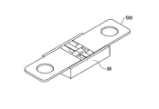
- FIG. 17 is a schematic view of the protection element shown in FIGS. 11 and 12 in which a portion including the fuse element material is covered with a cover, and is a perspective schematic view of a state in which the protection element is covered with an upper cover and a lower cover.
- FIG. 18 is a schematic perspective view with the upper cover of FIG. 15 removed.
- FIG. 19 is a schematic perspective view of the protection element according to the fourth embodiment.
- FIG. 19 is a schematic perspective view of the protection element according to the fourth embodiment.
- FIG. 20 is a schematic perspective view of the protection element shown in FIG. 19 seen from the side opposite to FIG.
- FIG. 21 is a schematic perspective view of the protection element shown in FIGS. 19 and 20 after the fuse element material is cut, and corresponds to FIG. 19.
- 22 is a schematic perspective view of the protection element shown in FIGS. 19 and 20 after the fuse element material is cut, and corresponds to FIG.
- FIG. 23 is a schematic perspective view of the protection element according to the fifth embodiment.
- FIG. 24 is a schematic side view of the protection element shown in FIG. 23 as seen from the direction of arrow A shown in FIG.
- FIG. 25 is a schematic perspective view of the protective element shown in FIGS. 23 and 24, in which the fuse element material is cut, as seen from the direction corresponding to FIG. 23.
- FIG. 26 is a schematic side view of the protection element shown in FIGS. 23 and 24, showing a state in which the fuse element material is cut, as seen from the direction corresponding to FIG.
- FIG. 27 is a schematic perspective view
- FIG. 1 is a schematic plan view of an example of the protection element according to the first embodiment.
- 2 is a schematic cross-sectional view of the protection element shown in FIG. 1 taken along the line II-II ′ in FIG. 1
- FIG. 3 shows the protection element shown in FIG.
- FIG. 3 is a schematic sectional view taken along line III ′.
- a protective element 100 shown in FIGS. 1 to 3 is a fuse element arranged between a first electrode 1, a second electrode 2 having a spring property, and a first electrode 1 and a second electrode 2. And a material 3.
- the fuse element material 3 is sandwiched and supported by the first electrode 1 and the bent second electrode 2.
- the first electrode 1 is made of a conductive material.
- a conductive material for example, metal (including alloy) can be used. Specific examples of the conductive material include copper, brass, nickel, stainless steel, 42 alloy and the like. As will be described later, when the first electrode 1 itself also has the same spring property as the second electrode 2, the same material as the second electrode 2 can be used.
- the shape of the first electrode 1 (the shape of the portion other than the claw portion described later) is rectangular in plan view as a whole, but any shape may be used as long as the effects of the present invention are exhibited. You can In the example shown in FIG. 1, the first electrode 1 is a plate-shaped member.
- the first electrode 1 is provided at one end 1A thereof with a claw portion 1a for stably supporting the fuse element material 3.
- the tip 1aA of the claw portion 1a included in the first electrode 1 is bent toward the fuse element material 3 in order to support the fuse element material 3 more stably, Is equipped with. That is, the bent portion 1aAa has a function of preventing the fuse element material 3 from coming off.
- the first electrode 1 has one claw, but the number of claws may be two or more. When a plurality of claw portions are provided, those claw portions may be the same as or different from each other. Further, the position of the claw portion 1a at the one end 1A can be arbitrarily selected as long as it can be stably supported.
- FIG. 4 is a schematic plan view of another example of the protection element according to the first embodiment.
- the first electrode 21 includes two claw portions (21a, 21b).
- members having the same reference numerals as those in FIG. 4 are shown in FIG. 4, and are shown in FIG. 4, members having the same reference numerals as those in FIG.
- the thickness of the first electrode 1 is not limited, but it can be set to 0.05 to 0.5 mm as a guideline.
- the second electrode 2 is made of a conductive material having a spring property.
- the conductive material having spring properties include metals (including alloys). Among them, metal materials (including alloys) having low resistance and suitable for leaf spring materials are preferable, and specific materials include phosphor bronze, copper alloy, titanium copper, Corson alloy, beryllium copper and the like. ..
- spring property refers to a property of deforming when a force is applied and returning to the original state when the force is removed.
- the “spring property” supports the fuse element material 3 in a bent state. It means that the existing electrode returns to the position before being bent after the fuse element material 3 is cut by the overcurrent. That is, in the protection element 100 of this embodiment, the fuse element material 3 is supported so as to be sandwiched in a state where the electrodes are bent within a range in which elastic deformation is possible.
- the bent state may be the whole electrode or a part of the electrode.
- the shape of the second electrode 2 shown in FIG. 1 is generally rectangular in plan view, but any shape can be used as long as the effects of the present invention are exhibited.
- the second electrode 2 is a plate-shaped member.
- the second electrode 2 is provided at one end 2A thereof with a claw portion 2a and a claw portion 2b for supporting the fuse element material 3.
- the tip 2aA of the claw portion 2a included in the second electrode 2 has a bent portion 2aAa bent toward the fuse element material 3 in order to more stably support the fuse element material 3. Is equipped with.
- the tip 2bA of the claw portion 2b also includes a bent portion 2bAa.
- the second electrode 2 includes two claws 2a and 2b, but the number of claws may be one, or may be three or more.
- claw portions 2a and 2b When a plurality of claw portions 2a and 2b are provided as in the example shown in FIG. 1, those claw portions may be the same as or different from each other.
- the configuration of the claw portions 2a and 2b greatly affects the cutting or shearing of the fuse element material 3.
- “shear” refers to an action of cutting the fuse element material.
- the “shearing force” described later means that the fuse element material 3 is slid along the surface when a pair of forces in opposite directions are applied in parallel to a certain cross section of the fuse element material 3. Receiving, but the force that gives such an action. A pair of forces in opposite directions are applied to the fuse element material 3 from the claw portions 1a of the first electrode 1 and the claw portions 2a and 2b of the second electrode 2, respectively.
- the thickness of the second electrode 2 is not limited, but it can be set to 0.05 to 0.5 mm as a guideline.
- the second electrodes 2 may have the same thickness as a whole, but may have portions having different thicknesses. For example, by making only the portions (the claw portions 2a and 2b in the example of FIG. 1) that sandwich and support the fuse element material 3 thin, and the other portions not thin, as a connection terminal to the outside. The rigidity of the fuse element material can be enhanced while maintaining the rigidity of the fuse element.
- a known metal working method such as rolling can be used.
- the fuse element material 3 a material used for a known fuse element can be used.
- the fuse element material 3 is a member that does not substantially deform (within the range where the effect of the present invention is exerted) even when a force is applied at a temperature due to energization during normal operation of the device including the protection element. Otherwise, the fuse element material 3 will be deformed over time and will no longer function as a fuse element material. Therefore, the fuse element material 3 is not a thin piece or the like that deforms when a force is applied, but is a bulk material (a plate shape, a rod shape, a square shape, or the like) that does not deform even when a force is applied.
- the fuse element material 3 is sandwiched and supported by the first electrode 1 and the second electrode 2 in a bent state. More specifically, in the example shown in FIGS. 1 to 3, the fuse element material 3 includes a claw portion 1a included in the first electrode 1 and a claw portion 2a in a bent state included in the second electrode 2, It is sandwiched and supported by the claw portion 2b.
- the claw portions 1a included in the first electrode 1 and the claw portions 2a and 2b included in the second electrode 2 are alternately arranged as shown in FIG. That is, it is preferable that the claw portion 2a, the claw portion 1a, and the claw portion 2b are arranged in this order so as not to overlap in a plan view.
- the fuse element material 3 has a configuration in which the dimensions (thickness, width, length, etc., depending on the shape) are not deformed (within the range where the effect of the present invention is exerted) by energization during normal operation, an overcurrent flows, Any size that can be cut by the first electrode 1 and the bent second electrode 2 can be taken.
- the fuse element material 3 is vertically sandwiched and supported together with the claw portions 1a of the first electrode 1 in a state where the claw portions 2a and 2b of the second electrode 2 having a spring property are bent. ..
- the second electrode 2 is bent so as to return to the claw portion 1a side of the first electrode 1. For this reason, a force is applied to the fuse element material 3 from the claw portions 2a and 2b of the second electrode 2 toward the claw portion 1a of the first electrode 1, and at the same time, from the first electrode 1 to the second electrode element 2.
- a force is applied to the electrode 2. That is, a force is applied to the fuse element material 3 in opposite directions from the first electrode 1 and the second electrode 2.
- the protective element 100 is different from the above-described spring-based type protective element that separates the connection between the fuse element and the spring in that the fuse element material 3 itself is physically cut.
- the fuse element material 3 is not melted and simply cut in a softened state, but when it is cut in a partially unmelted state, it can be said that the shearing force causes shearing. In many cases, the fuse element material 3 may be cut in a manner that cannot be said to be shearing due to shearing force.
- the protection element 100 includes a cut surface of the fuse element material 3 cut by the claw portion 1a of the first electrode 1 and a cut surface of the fuse element material 3 cut by the claw portions 2a, 2b of the second electrode 2.
- the distance is rapidly increased by the elastic restoring force (the force returning to the original state by the spring property) of the claw portions 2a and 2b of the second electrode 2. Therefore, the arc discharge can be quickly stopped.
- the fuse element material 3 can be cut at a temperature at which the fuse element material 3 becomes inflexible before reaching the molten state, that is, at a temperature lower than the temperature at which the fuse element material 3 reaches the molten state. It can be reduced.
- the fuse element material 3 may be made of a laminated body including a high melting point metal layer and a low melting point metal layer. In the case of this configuration, while the rigidity of the fuse element material 3 is maintained by the high melting point metal layer, the fuse element material 3 is softened at a lower temperature by providing the low melting point metal layer, or in a semi-molten state, the fuse element Allows the material to be cut.
- solder such as Pb-free solder containing Sn as a main component. Since the melting point of Sn is 217 ° C., the solder containing Sn as a main component has a low melting point and becomes soft at a low temperature.
- the refractory metal used for the refractory metal layer it is preferable to use Ag, Cu or an alloy containing them as a main component.
- the melting point of Ag is 962 ° C.
- the high melting point metal layer made of an alloy containing Ag as a main component can maintain rigidity at a temperature at which the low melting point metal layer becomes soft.
- 5 to 8 are perspective views schematically showing an example of the structure of the laminated body.
- the laminated body (fuse element material) 3A shown in FIG. 5 has a rectangular shape or a plate shape, and has a low melting point metal layer 3Aa as an inner layer and a high melting point metal layer 3Ab as an outer layer.
- the low melting point metal layer 3Aa may be the outer layer and the high melting point metal layer 3Ab may be the inner layer.
- the laminated body (fuse element material) 3B shown in FIG. 6 has a round bar shape, and has a low melting point metal layer 3Ba as an inner layer and a high melting point metal layer 3Bb as an outer layer.
- the low melting point metal layer 3Ba may be an outer layer and the high melting point metal layer 3Bb may be an inner layer.
- the laminated body (fuse element material) 3C shown in FIG. 7 is rectangular or plate-shaped, and has a two-layer structure in which a low melting point metal layer 3Ca and a high melting point metal layer 3Cb are laminated.
- the laminated body (fuse element material) 3D shown in FIG. 8 has a rectangular or plate shape and has a three-layer structure in which the low melting point metal layer 3Da is sandwiched between the upper and lower refractory metal layers 3Db and 3Dc. It is a thing. Conversely, a high melting point metal layer may be sandwiched between two low melting point metal layers to form a three-layer structure.
- the laminates (fuse element materials) 3A to 3D shown in FIGS. 5 to 8 are two-layer or three-layer laminates, but the number of low-melting point metal layers and high-melting point metal layers is not particularly limited.
- the fuse element material may be a laminate of four or more layers.
- At least one of the first electrode 1 and the second electrode 2 and the fuse element material 3 are preferably joined by solder, and both the first electrode 1 and the second electrode 2 are the fuse element material 3 Is more preferably joined by soldering. This is to reduce the electric resistance between the fuse electrode material 3 and the first electrode 1 or the second electrode 2.
- solder a known material can be used, but a material containing Sn as a main component is preferable from the viewpoint of resistivity and melting point.
- FIG. 9 is a schematic plan view of the protection element according to the second embodiment.
- Members using the same reference numerals as those in the first embodiment have the same configuration, and the description thereof will be omitted. Further, description may be omitted for members having the same function even if the reference numerals are different from those in the first embodiment.
- the main difference between the protective element according to the second embodiment and the protective element according to the first embodiment is that the first electrode and the second electrode have external terminal holes. That is, the protection element according to the first embodiment is used with the external terminals attached separately, but in the protection element according to the second embodiment, the first electrode and the second electrode are formed integrally with the external terminal. It is a composition.
- the protection element 400 shown in FIG. 9 is arranged between the first electrode 41, the second electrode 42 having a spring property, and the first electrode 41 and the second electrode 42.
- a fuse element material 3 is provided, and the fuse element material 3 is sandwiched and supported by the first electrode 41 and the second electrode 42 in a bent state.
- the first electrode 41 and the second electrode 42 are provided with external terminal holes 45 and 46, respectively.
- the external terminal holes 45 and 46 are provided in each of the first electrode 41 and the second electrode 42. Of the pair of external terminal holes 45, 46, one external terminal hole can be used for connecting to the power source side, and the other external terminal hole can be used for connecting to the load side.
- the shape of the external terminal holes 45 and 46 is not particularly limited as long as it can be engaged with a power source side or load side terminal (not shown).
- the external terminal holes 45 and 46 shown in FIG. 9 are through holes having no open portion, but may be, for example, a pawl shape having an open portion in part as shown in FIG.
- the first electrode 41 can be made of the same material as the first electrode 1 of the first embodiment. Further, also for the second electrode 42, the same material as that of the second electrode 2 of the first embodiment can be used.
- FIG. 10 is a schematic plan view of a modified example of the protection element according to the second embodiment.
- the shape of the external terminal hole is different from that in the example shown in FIG.
- the protection element 400A shown in FIG. 10 is arranged between the first electrode 41AA, the second electrode 42AA having a spring property, and the first electrode 41AA and the second electrode 42AA.
- a fuse element material 3 is provided, and the fuse element material 3 is sandwiched and supported by the first electrode 41AA and the second electrode 42AA in a bent state, and the first electrode 41AA and the second electrode 42AA are supported.
- 42AA is provided with external terminal holes 45A and 46A having open portions 45Aa and 46Aa, respectively.
- the position of the open part of the external terminal hole can be selected as appropriate.
- the open portions 45AA and 46Aa of the external terminal holes 45A and 46A are provided on the opposite sides of the first electrode 41AA and the second electrode 42AA, respectively, on the side opposite to the side connected to the fuse element material 3. Located, but may be in another position.
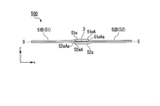
- FIG. 11 and 12 are schematic views of the protection element according to the third embodiment
- FIG. 11 is a schematic perspective view
- FIG. 12 is a schematic side view seen from the direction of arrow A shown in FIG. 11.
- Members using the same reference numerals as those in the above-described embodiment have the same configuration, and the description thereof will be omitted. Further, description may be omitted for members having the same function even if the reference numerals are different from those of the above-described embodiment.
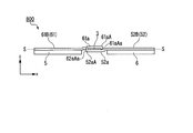
- the dotted line SS indicates the portions of the first electrode 51 and the second electrode 52 excluding the claw portions (the portions that do not substantially change even after the fuse element material 3 is cut) 51B and 52B.
- the surface (SS plane) connecting the center planes in the thickness direction is shown.
- the main difference between the protection element according to the third embodiment and the protection element according to the above-described embodiment is that the first electrode has a spring property in addition to the second electrode.
- the protection element 500 shown in FIGS. 11 and 12 includes a first electrode 51 having a spring property, a second electrode 52 having a spring property, a first electrode 51 and a second electrode 52. And a fuse element material 3 disposed between the fuse element material 3 and the fuse element material 3, and the fuse element material 3 is sandwiched and supported by the first electrode 51 in a bent state and the second electrode 52 in a bent state. There is.
- the first electrode 51 and the second electrode 52 have external terminal holes 55 and 56, respectively.
- the first electrode 51 has a spring property, the same material as that of the second electrode 2 of the first embodiment can be used.
- the first electrode 51 is provided at one end 51A thereof with a claw portion 51a for stably supporting the fuse element material 3.
- the tip 51aA of the claw portion 51a included in the first electrode 51 is provided with a bent portion 51aAa that is bent toward the fuse element material 3 side so that the fuse element material 3 can be supported more stably.
- the external terminal hole 55 included in the first electrode 51 can have the same configuration as the external terminal hole 45 included in the first electrode 41 of the second embodiment or the external terminal hole 45A included in the first electrode 41AA. ..
- the first electrode 51 has a structure having the external terminal hole 55, but the first electrode 51 may not have the external terminal hole.
- the first electrodes 51 may have the same thickness as a whole, but may have portions having different thicknesses.
- the rigidity as a connection terminal to the outside can be improved by thinning only the portion that sandwiches and supports the fuse element material (the claw portion 51a in the example of FIG. 11) and does not thin the other portions. It is possible to improve the spring property of sandwiching the fuse element material 3 while maintaining it.
- a known metal working method such as rolling can be used.
- the second electrode 52 can be made of the same material as the second electrode 2 of the first embodiment.
- the second electrode 52 is provided at one end 52A thereof with claw portions 52a and 52b for stably supporting the fuse element material 3. Further, the tip 52aA of the claw portion 52a and the tip (not shown) of the claw portion 52b included in the second electrode 52 are bent toward the fuse element material 3 side so that the fuse element material 3 can be supported more stably.
- the bent portion 52aAa and the bent portion (not shown) are provided.
- the external terminal hole 56 included in the second electrode 52 can have the same configuration as the external terminal hole 46 included in the second electrode 42 of the second embodiment or the external terminal hole 46A included in the second electrode 42AA. .. In the protection element 500 shown in FIGS. 11 and 12, the second electrode 52 has the external terminal hole 56, but the external terminal hole may not be provided.
- FIGS. 13 and 14 are schematic diagrams of the protection element 500 shown in FIGS. 11 and 12 after the fuse element material is cut.
- 13 is a schematic perspective view
- FIG. 14 is a schematic side view seen from the direction of arrow A shown in FIG.
- the direction indicated by reference numeral x in FIG. 14 is a direction parallel to the SS plane, and is a direction connecting the portions 51B and 52B excluding the claw portions of the first electrode 51 and the second electrode 52, respectively.
- the direction indicated by the symbol z is parallel to the thickness direction of the first electrode 51 or the second electrode 52.
- the reference numeral 3'in FIGS. 13 and 14 is the fuse element material 3 divided by cutting.
- the claw portion 51a which is the bent portion of the first electrode 51 (in other words, the portion responsible for the spring property), is S in the z direction before the fuse element material 3 is cut. It was located above the ⁇ S plane (see FIG. 12), but after the fuse element material 3 was cut, it was located below the SS plane (see FIG. 14). In other words, the claw portion 51a of the first electrode 51 is positioned below the SS plane in the state where there is no force for bending, but the fuse element material 3 is bent so as to be pressed from above. It was being done. The claw portion 51a of the first electrode 51 has no force to bend by cutting the fuse element material 3 and returns to the original state by the elastic restoring force. That is, the claw portion 51a of the first electrode 51 is in the state shown in FIGS. 13 and 14 where no external force is applied.
- the claw portions 52a and 52b which are the bent portions of the second electrode 52 (in other words, the portions that have spring properties), are in the z direction from the SS plane before the fuse element material 3 is cut. Is also located on the lower side (see FIG. 12), but is located above the SS plane after cutting the fuse element material 3 (see FIG. 14). In other words, the claw portions 52a and 52b of the second electrode 52, which are located above the SS plane in the state where there is no bending force, are bent so as to push the fuse element material 3 from below. It was The claws 52a and 52b of the second electrode 52 are the ones that have no force to bend due to the cutting of the fuse element material 3 and have returned to their original state by the elastic restoring force. That is, the second electrode 52 (the portion 52B of the second electrode 52 excluding the claw portions and the claw portions 52a, 52b) is in a state shown in FIGS. 13 and 14 where no external force is applied. ..
- the method of bending the first electrode 51 and the second electrode 52 (the positions of the claw portion 51a and the claw portions 52a and 52b before and after cutting the fuse element material 3) in FIGS. It can be set arbitrarily as long as the effect of
- 15 and 16 show schematic views of a protection element in which a first electrode having a spring property has two claws.
- 15 is a schematic perspective view
- FIG. 16 is a schematic perspective view after interruption due to overcurrent.
- Members using the same reference numerals as those in the above-described embodiment have the same configuration, and the description thereof will be omitted. Further, description may be omitted for members having the same function even if the reference numerals are different from those of the above-described embodiment.
- the protection element 600 shown in FIG. 15 includes a first electrode 61 having a spring property, a second electrode 52 having a spring property, and a space between the first electrode 61 and the second electrode 52. And the fuse element material 3 disposed in the fuse element material 3.
- the fuse element material 3 is sandwiched and supported by the first electrode 61 in a bent state and the second electrode 52 in a bent state.
- the first electrode 61 is provided at its one end with two claw portions (61a, 61b) for stably supporting the fuse element material 3. Further, the first electrode 61 has an external terminal hole 65.
- the claw portions 61a and 61b which are the bent portions (portions that bear the spring property) in the first electrode 61, are formed in the thickness direction before cutting the fuse element material 3. It was located above the portion 61B of the electrode 61 of FIG. 1 excluding the claw portion (see FIG. 15), but after the cutting of the fuse element material 3 was located below the portion 61B (see FIG. 16). .. In other words, the claw portions 61a and 61b of the first electrode 61 were located below the portion 61B when there was no bending force, but the fuse element material 3 was bent so as to be pushed from above. It was being done.
- the claw portions 61a and 61b of the first electrode 61 are restored to their original state because the force to bend the fuse element material 3 is lost. That is, the claw portions 51a and 51b of the first electrode 51 are in a state shown in FIG. 16 in which no external force is applied.
- the claws 52a and 52b which are the bent portions (portions bearing the spring property) in the second electrode 52, are in the z direction, and the claws of the second electrode 52 before the fuse element material 3 is cut. Although it is located below the portion 52B except for (see FIG. 15), it is located above the portion 52B after cutting the fuse element material 3 (see FIG. 16).
- the claw portions 52a and 52b of the second electrode 52 were positioned above the portion 52B when there was no force for bending, but they were bent so as to push up the fuse element material 3 from below. Was there.
- the claw portions 52a and 52b of the second electrode 52 are restored to their original state because the force of bending the fuse element material 3 is lost. That is, the second electrode 52 (the portion 52B of the second electrode 52 excluding the claw portions and the claw portions 52a and 52b) is in a state in which no external force is applied in the state shown in FIG.
- FIGS. 11 and 12 are schematic views of a mode in which the portion including the fuse element material 3 is covered with the cover 8 in the protection element 500 shown in FIGS. 11 and 12, and FIG. 17 is an upper cover 8A and a lower cover.
- 8B is a schematic perspective view in a state of being covered with 8B
- FIG. 18 is a schematic perspective view in a state of removing the upper cover 8A.
- the cover 8 (upper cover 8A and lower cover 8B) may be made of, for example, an insulating resin.
- the cover 8 (the upper cover 8A and the lower cover 8B) can also be used for the protection elements according to other embodiments.
- FIG. 19 and 20 are schematic views of the protection element according to the fourth embodiment, FIG. 19 is a perspective schematic view, and FIG. 20 is a perspective schematic view seen from the side opposite to FIG.
- Members using the same reference numerals as those in the above-described embodiment have the same configuration, and the description thereof will be omitted. Further, description may be omitted for members having the same function even if the reference numerals are different from those of the above-described embodiment.
- the protection element according to the fourth embodiment is mainly different from the protection element according to the above-described embodiment in that a heating element that heats the fuse element material and a third electrode that energizes the heating element are further provided. is there.
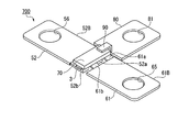
- the protection element 700 according to the fourth embodiment shown in FIGS. 19 and 20 is different from the protection element 600 shown in FIG. 15 in that a heating element that heats the fuse element material and a third electrode that conducts electricity to the heating element.
- the protective element 700 is arranged between the first electrode 61 having a spring property, the second electrode 52 having a spring property, and the first electrode 61 and the second electrode 52.
- the fuse element material 3 is sandwiched between and supported by the first electrode 61 in a bent state and the second electrode 52 in a bent state.
- the heating element 70 that heats the heating element 3 and the third electrode 80 that energizes the heating element 70 are provided.
- the first electrode 61, the second electrode 52, and the third electrode 80 have external terminal holes 65, 56, 81, respectively.
- the heating element 70 and the third electrode 80 are connected by the conductive connecting portion 90.
- the third electrode 80 is separated from both the first electrode 61 and the second electrode 52 and is not connected.
- the heating element 70 is connected to the first electrode 61. More specifically, the heating element 70 is connected to the claw portions 61a and 61b of the first electrode 61.
- the heating element 70 may be configured to be bonded to either the second electrode 52 or the fuse element material 3.
- the heating element 70 is a member that has a relatively high resistance value and generates heat when energized, and may be made of, for example, W, Mo, Ru, or the like.
- the third electrode 80 is made of a conductive material, and the same material as the first electrode 1 described above can be used.
- the protective element 700 includes the heating element 70 and the third electrode 80, and the third electrode 80 is connected to the first electrode 61.
- the fuse element material 3 can be heated by passing a current between the first electrode 61 and the heating element 70 to generate heat. Thereby, the fuse element material 3 can be cut.
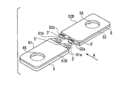
- 21 and 22 are schematic perspective views of the protection element 700 shown in FIGS. 19 and 20 after the fuse element material is cut. 21 and 22 correspond to FIGS. 19 and 20, respectively.
- the claw portions 61a and 61b which are the bent portions of the first electrode 61, exclude the claw portions of the first electrode 61 before cutting the fuse element material 3 in the thickness direction. Although it was located above the portion 61B (see FIG. 20), it is located below the portion 61B after cutting the fuse element material 3 (see FIG. 22). In other words, the claw portions 61a and 61b of the first electrode 61, which are positioned below 61B in the state where there is no force to bend, are bent so as to push the fuse element material 3 from above. The force for bending the fuse element material 3 is lost and the fuse element material 3 returns to its original state.
- the claw portions 52a and 52b which are the bent portions of the second electrode 52, are located below the portion 52B of the second electrode 52 excluding the claw portions in the thickness direction before the fuse element material 3 is cut. Although it was located (see FIG. 20), it is located above the portion 52B of the second electrode 52 excluding the claw portion after the fuse element material 3 is cut (see FIG. 22). In other words, the claws 52a and 52b of the second electrode 52 are located above the part 52B of the second electrode 52 excluding the claws in the state in which there is no force to bend the fuse element material 3 below. Although it was bent so as to be pushed up from above, the force to bend it by cutting the fuse element material 3 disappeared, and it returned to the original state.
- the heating element 70 Before the fuse element material 3 was cut, the heating element 70 had its lower surface in contact with the claw portions 61a and 61b of the first electrode 61, but after the fuse element material 3 was cut, the heating element 70 had its lower surface.
- the claw portions 52a and 52b of the second electrode 52 are in contact with each other. Further, the connecting portion 90 is separated from the third electrode 80, and the power supply to the heating element 70 is cut off, so that the heat generation of the heating element 70 is stopped.
- FIG. 23 and 24 are schematic views of the protection element according to the fifth embodiment, FIG. 23 is a schematic perspective view, and FIG. 24 is a schematic side view seen from the direction of arrow A shown in FIG.
- Members using the same reference numerals as those in the above-described embodiment have the same configuration, and the description thereof will be omitted. Further, description may be omitted for members having the same function even if the reference numerals are different from those of the above-described embodiment.
- the protection element according to the fifth embodiment is connected to the protection element according to the above embodiment so that the first terminal member overlaps in the thickness direction of the first electrode, and the thickness direction of the second electrode.
- the main difference is that the second terminal member is connected so as to overlap.
- the first terminal member and the second terminal member respectively reinforce the rigidity for connecting the first electrode and the second electrode to the outside and reduce the electric resistance.
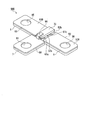
- the protection element 800 shown in FIG. 23 is different from the protection element 600 shown in FIG. 15 in that the first terminal member 5 is connected to the first electrode 61 and the second terminal member 6 is connected to the second electrode 52. This is an example of being connected.
- the first terminal member 5 has an external terminal hole at a position corresponding to the external terminal hole 65 included in the first electrode 61.
- the second terminal member 6 has an external terminal hole at a position corresponding to the external terminal hole 56 included in the second electrode 52.
- First terminal member, second terminal member Examples of the material of the first terminal member 5 and the second terminal member 6 include copper and brass. Among them, brass is preferable from the viewpoint of strengthening the rigidity. Among them, copper is preferable from the viewpoint of reducing electric resistance. The materials of the first terminal member 5 and the second terminal member 6 may be the same or different.
- first terminal member 5 and the second terminal member 6 As a method of connecting the first terminal member 5 and the second terminal member 6 to the first electrode 61 and the second electrode 52, a known method can be used, and for example, joining by welding, Mechanical joining such as rivet joining or screw joining may be mentioned.
- the thicknesses of the first terminal member 5 and the second terminal member 6 are not limited, but can be set to 0.3 to 1.0 mm as a guide.
- the thicknesses of the first terminal member 5 and the second terminal member 6 may be the same or different.
- the first terminal member 5 and the second terminal member 6 are the portion 61B of the first electrode 61 excluding the claw portions 61a and 61b, and the second electrode. Although it is provided so as to cover the entire surface of the portion 52B except the claw portions 52a and 52b of 52, the covering range and the covering shape can be arbitrarily set as long as at least one of the effect of strengthening the rigidity and reducing the electric resistance is exhibited. Further, the portion 61B of the first electrode 61 excluding the claw portions 61a and 61b and the portion 52B of the second electrode 52 excluding the claw portions 52a and 52b need not be covered to the positions of the external terminal holes 65 and 56, respectively. , The first terminal member 5 and the second terminal member 6 may be connected so as to partially overlap with each other.
- 25 and 26 are schematic diagrams of the protection element 800 shown in FIGS. 23 and 24 after the fuse element material is cut.
- 25 is a schematic perspective view
- FIG. 26 is a schematic side view seen from the direction of arrow A shown in FIG.
- Members using the same reference numerals as those in the above-described embodiment have the same configuration, and the description thereof will be omitted. Further, description may be omitted for members having the same function even if the reference numerals are different from those of the above-described embodiment.
- the first electrode 61 and the second electrode 52 include the first terminal member 5 and the second terminal member 6, respectively, so that the rigidity is enhanced. Therefore, the total thickness of each of the first electrode 61 and the second electrode 52 can be reduced, and the elasticity can be easily adjusted. That is, the adjustment range of the thickness of the first electrode 61 and the second electrode 52 is widened. Further, in the first electrode 61 or the second electrode 52, the first terminal member 5 and the second terminal member 6 are configured in a configuration in which only the portion for sandwiching and supporting the fuse element material as described above is thinned. With the provision of, it becomes possible to make that portion even thinner.
- FIG. 27 is a schematic perspective view of the protection element according to the sixth embodiment.
- Members using the same reference numerals as those in the above-described embodiment have the same configuration, and the description thereof will be omitted. Further, description may be omitted for members having the same function even if the reference numerals are different from those of the above-described embodiment.
- the protection element according to the sixth embodiment has a heating element that heats the fuse element material, a third electrode that conducts electricity to the heating element, a heating element and a third electrode.
- the main difference is that it further includes a connecting part that connects the third terminal member to the third electrode in the thickness direction so as to overlap with each other. Similar to the first terminal member and the second terminal member, the third terminal member reinforces the rigidity for connecting the third electrode to the outside and reduces the electric resistance.
- the protection element 900 shown in FIG. 27 is different from the protection element 700 shown in FIG. 19 in that the first terminal member 5 is connected to the first electrode 61 and the second terminal member 6 is connected to the second electrode 52.
- the third terminal member 7 is connected to the third electrode 80.
- the first terminal member 5 has an external terminal hole at a position corresponding to the external terminal hole 65 included in the first electrode 61.
- the second terminal member 6 has an external terminal hole at a position corresponding to the external terminal hole 56 included in the second electrode 52.
- the third terminal member 7 has an external terminal hole at a position corresponding to the external terminal hole 81 included in the third electrode 80.
- the portion 61B of the first electrode 61 excluding the claw portions and the portion 52B of the second electrode excluding the claw portions need not cover the positions of the external terminal holes 56 and 65, respectively.
- a part of the second terminal member 6 may be connected so as to overlap with each other.
- the third electrode 80 may be omitted and the connecting portion 90 may be directly connected to the third terminal member 7.
- the material of the third terminal member 7 may be the same as or may be different from either. Further, the material of the third terminal member 7, the material of the first terminal member 5, and the material of the second terminal member 6 may be the same.
- the first terminal member 5 or the second terminal member 6 is connected to the first electrode 61 and the second electrode 52.
- the thickness of the third terminal member 7 is approximately the same as the thickness of the first terminal member 5 or the second terminal member 6, and may be the same as or different from one of them.
- the thickness of the third terminal member 7, the thickness of the first terminal member 5, and the thickness of the second terminal member 6 may all be the same.
Landscapes
- Fuses (AREA)
- Bipolar Transistors (AREA)
- Emergency Protection Circuit Devices (AREA)
- Amplifiers (AREA)
Abstract
Description
本願は、2018年11月7日に、日本に出願された特願2018-209897号に基づき優先権を主張し、その内容をここに援用する。
かかる保護素子は、リフローによる表面実装が困難であり、部品実装の効率が低くなるため、近年では表面実装型の保護素子が開発されている(例えば、特許文献1、2参照)。
また、上記のバネを利用する保護素子では、使用環境でヒューズエレメントとバネとの接合強度が経時変化で低下しやすく、長期安定性が懸念される。
図1は、第1実施形態に係る保護素子の一例の平面模式図である。図2は、図1に示した保護素子を、図1中のII-II’線で切った断面模式図であり、図3は、図1に示した保護素子を、図1中のIII-III’線で切った断面模式図である。
第1の電極1は、導電材料からなる。導電材料としては、例えば、金属(合金を含む)を用いることができる。具体的な導電材料の例としては、銅、黄銅、ニッケル、ステンレス、42アロイなどが挙げられる。後述するが、第1の電極1自体も、第2の電極2と同様にバネ性を有する場合には、第2の電極2と同様の材料を用いることができる。
第2の電極2は、バネ性を有する導電材料からなる。バネ性を有する導電材料としては、金属(合金を含む)を例示できる。その中でも、低抵抗で板バネ材料に適した金属材料(合金を含む)であることが好ましく、具体的な材料としては、りん青銅、銅合金、チタン銅、コルソン合金、ベリリウム銅などが挙げられる。
ヒューズエレメント材3としては、公知のヒューズエレメントに用いられる材料のものを用いることができる。ヒューズエレメント材3は、保護素子を備える装置が通常の作動中の通電による温度では、力を加えても実質的に(本発明の効果を奏する範囲で)変形しない部材である。さもなければ、ヒューズエレメント材3が経時的に変形して、ヒューズエレメント材としての機能を果たさなくなるからである。従って、ヒューズエレメント材3は、力を加えると変形する薄片などではなく、力を加えても変形しないバルク材(板状、棒状、角材状など)である。
図9は、第2実施形態に係る保護素子の平面模式図である。第1実施形態と同じ符号を用いた部材は同じ構成を有するものであり、説明を省略する。また、第1実施形態と符号が異なっていても機能が同じ部材については説明を省略する場合がある。
外部端子孔45、46は、第1の電極41及び第2の電極42のそれぞれに備えられている。一対の外部端子孔45、46のうち、一方の外部端子孔は電源側へ接続するために用いることができ、他方の外部端子孔は負荷側へ接続するために用いることができる。ここで、外部端子孔45、46の形状は、図示しない電源側あるいは負荷側の端子に係合可能な形状であれば特に制限はない。図9に示す外部端子孔45、46は開放部分がない貫通穴であるが、例えば、図10に示すように一部に開放部分を有するつめ形状などでもよい。
図11及び図12は、第3実施形態に係る保護素子の模式図であり、図11は斜視模式図、図12は、図11に示す矢印Aの方向から見た側面模式図である。上記実施形態と同じ符号を用いた部材は同じ構成を有するものであり、説明を省略する。また、上記実施形態と符号が異なっていても機能が同じ部材については説明を省略する場合がある。図12において、S-Sの点線は、第1の電極51及び第2の電極52のそれぞれの爪部を除く部分(ヒューズエレメント材3の切断後にも実質的に変わらない部分)51B、52Bの厚み方向の中心面を繋いだ面(S-S面)を示す。
第1の電極51はバネ性を有するので、第1実施形態の第2の電極2と同様な材料を用いることができる。第1の電極51は、その一端51Aに、ヒューズエレメント材3を安定に支持するための爪部51aを備えている。また、第1の電極51が備える爪部51aの先端51aAは、ヒューズエレメント材3をより安定に支持可能とするために、ヒューズエレメント材3側に折れ曲がった屈曲部51aAaを備えている。第1の電極51が有する外部端子孔55は、第2実施形態の第1の電極41が有する外部端子孔45や第1の電極41AAが有する外部端子孔45Aと同様な構成とすることができる。図11に示す保護素子500では、第1の電極51は外部端子孔55を有する構成であるが、外部端子孔を有さなくてもよい。
第2の電極52は、第1実施形態の第2の電極2と同様な材料を用いることができる。第2の電極52は、その一端52Aに、ヒューズエレメント材3を安定に支持するための爪部52a、52bを備えている。また、第2の電極52が備える爪部52aの先端52aA及び爪部52bの先端(不図示)はそれぞれ、ヒューズエレメント材3をより安定に支持可能とするために、ヒューズエレメント材3側に折れ曲がった屈曲部52aAa、屈曲部(不図示)を備えている。第2の電極52が有する外部端子孔56は、第2実施形態の第2の電極42が有する外部端子孔46や第2の電極42AAが有する外部端子孔46Aと同様な構成とすることができる。図11及び図12に示す保護素子500では、第2の電極52は外部端子孔56を有する構成であるが、外部端子孔を有さなくてもよい。
図19及び図20は、第4実施形態に係る保護素子の模式図であり、図19は斜視模式図、図20は、図19とは反対側から見た斜視模式図である。上記実施形態と同じ符号を用いた部材は同じ構成を有するものであり、説明を省略する。また、上記実施形態と符号が異なっていても機能が同じ部材については説明を省略する場合がある。
図23及び図24は、第5実施形態に係る保護素子の模式図であり、図23は斜視模式図、図24は、図23に示す矢印Aの方向から見た側面模式図である。上記実施形態と同じ符号を用いた部材は同じ構成を有するものであり、説明を省略する。また、上記実施形態と符号が異なっていても機能が同じ部材については説明を省略する場合がある。
第1の端子部材5、及び、第2の端子部材6の材料としては、例えば、銅や黄銅などが挙げられる。そのうち、剛性強化の観点では、黄銅が好ましい。そのうち、電気抵抗低減の観点では、銅が好ましい。第1の端子部材5、及び、第2の端子部材6の材料は、同じでも異なっていてもよい。
図27は、第6実施形態に係る保護素子の斜視模式図である。上記実施形態と同じ符号を用いた部材は同じ構成を有するものであり、説明を省略する。また、上記実施形態と符号が異なっていても機能が同じ部材については説明を省略する場合がある。
第3の端子部材7の材料は、第1の端子部材5、及び、第2の端子部材6の材料が異なる場合には、いずれかと同じでもよいし、いずれとも異なってもよい。また、第3の端子部材7の材料、第1の端子部材5の材料、及び、第2の端子部材6の材料が同じでもよい。
1a、21a、21b、41a、51a、61a、61b 爪部
2、42、42AA、52 第2の電極
2a、2b、42a、42b、52a、52b 爪部
3 ヒューズエレメント材
5 第1の端子部材
6 第2の端子部材
7 第3の端子部材
8 カバー
45、45A、46、46A、55、56 外部端子孔
100、200、400、400A、500、600、700、800、900 保護素子
Claims (14)
- 第1の電極と、バネ性を有する第2の電極と、前記第1の電極と前記第2の電極との間に配置されたヒューズエレメント材とを備え、
前記ヒューズエレメント材は、前記第1の電極と撓ませた状態の前記第2の電極とによって挟み込まれて支持されている、保護素子。 - 過電流が流れたときに前記ヒューズエレメント材がせん断されるようなせん断力が、前記第1の電極及び前記第2の電極から前記ヒューズエレメント材に付与されている、請求項1に記載の保護素子。
- 前記第1の電極及び前記第2の電極の少なくとも一方と、前記ヒューズエレメント材とは、はんだによって接合されている、請求項1に記載の保護素子。
- 前記第1の電極及び前記第2の電極はそれぞれ、その一端に爪部を備え、
前記ヒューズエレメント材は、前記第1の電極の爪部と前記第2の電極の爪部とによって挟み込まれて支持されている、請求項1に記載の保護素子。 - 前記第1の電極及び前記第2の電極はそれぞれ、一つ又は複数の前記爪部を備え、前記ヒューズエレメント材は、前記第1の電極の爪部と前記第2の電極の爪部とが3つ以上交互に並んで挟み込まれて支持されている、請求項4に記載の保護素子。
- 前記第1の電極及び前記第2の電極が備える前記爪部の少なくとも一部の爪部の先端が、前記ヒューズエレメント材側に折れ曲がっている、請求項4に記載の保護素子。
- 前記第1の電極はバネ性を有し、
前記ヒューズエレメント材は、撓ませた状態の前記第1の電極と撓ませた状態の前記第2の電極とによって挟み込まれて支持されている、請求項1に記載の保護素子。 - 前記ヒューズエレメント材は、高融点金属層と低融点金属層とを含む積層体からなる、請求項1に記載の保護素子。
- 前記低融点金属層は、Pbフリーはんだからなり、前記高融点金属層は、Ag若しくはCu、又はAg若しくはCuを主成分とする合金からなる、請求項8に記載の保護素子。
- 前記第1の電極及び前記第2の電極はそれぞれ、外部端子孔を備える、請求項1に記載の保護素子。
- 前記第1の電極に第1の端子部材が接続され、前記第2の電極に第2の端子部材が接続されている、請求項1に記載の保護素子。
- さらに、前記ヒューズエレメント材を加熱する発熱体と、
前記発熱体に通電する第3の電極と、を備える、請求項1~11のいずれか一項に記載の保護素子。 - 前記発熱体は、一端が前記第3の電極に接続され、他端が前記ヒューズエレメント材、前記第1の電極及び前記第2の電極のうち、少なくとも1つに接続されている、請求項12に記載の保護素子。
- 前記第3の電極に第3の端子部材が接続されている、請求項12に記載の保護素子。
Priority Applications (3)
| Application Number | Priority Date | Filing Date | Title |
|---|---|---|---|
| US17/309,047 US11749482B2 (en) | 2018-11-07 | 2019-11-06 | Protection element |
| CN201980070686.2A CN112912986B (zh) | 2018-11-07 | 2019-11-06 | 保护元件 |
| KR1020217012044A KR102578064B1 (ko) | 2018-11-07 | 2019-11-06 | 보호 소자 |
Applications Claiming Priority (2)
| Application Number | Priority Date | Filing Date | Title |
|---|---|---|---|
| JP2018-209897 | 2018-11-07 | ||
| JP2018209897A JP2020077523A (ja) | 2018-11-07 | 2018-11-07 | 保護素子 |
Publications (1)
| Publication Number | Publication Date |
|---|---|
| WO2020095917A1 true WO2020095917A1 (ja) | 2020-05-14 |
Family
ID=70611501
Family Applications (1)
| Application Number | Title | Priority Date | Filing Date |
|---|---|---|---|
| PCT/JP2019/043373 Ceased WO2020095917A1 (ja) | 2018-11-07 | 2019-11-06 | 保護素子 |
Country Status (6)
| Country | Link |
|---|---|
| US (1) | US11749482B2 (ja) |
| JP (2) | JP2020077523A (ja) |
| KR (1) | KR102578064B1 (ja) |
| CN (1) | CN112912986B (ja) |
| TW (1) | TWI822900B (ja) |
| WO (1) | WO2020095917A1 (ja) |
Families Citing this family (1)
| Publication number | Priority date | Publication date | Assignee | Title |
|---|---|---|---|---|
| JP7329850B2 (ja) * | 2020-12-16 | 2023-08-21 | 太平洋精工株式会社 | 電気回路遮断装置 |
Citations (4)
| Publication number | Priority date | Publication date | Assignee | Title |
|---|---|---|---|---|
| JPS4845248U (ja) * | 1971-09-29 | 1973-06-13 | ||
| JPH0620574A (ja) * | 1992-07-03 | 1994-01-28 | Canon Inc | 温度ヒューズ |
| JP2012043573A (ja) * | 2010-08-17 | 2012-03-01 | Hinode Denki Seisakusho:Kk | 速断ヒューズ |
| WO2018159283A1 (ja) * | 2017-02-28 | 2018-09-07 | デクセリアルズ株式会社 | ヒューズ素子 |
Family Cites Families (29)
| Publication number | Priority date | Publication date | Assignee | Title |
|---|---|---|---|---|
| US2921167A (en) * | 1958-06-04 | 1960-01-12 | Stevens Mfg Co Inc | Fuse |
| US3198914A (en) * | 1962-04-18 | 1965-08-03 | Advance Transformer Co | Thermally operated electrical disconnect device |
| DE1991022U (de) * | 1967-06-27 | 1968-08-08 | Eastman Kodak Company, Rochester, N.Y. (V.St.A.) | Stromkreisunterbrecher |
| JPS6020574A (ja) | 1983-07-14 | 1985-02-01 | Tdk Corp | 半導体装置ならびにその製造方法 |
| JPS6084446A (ja) | 1983-10-14 | 1985-05-13 | Nissan Motor Co Ltd | シヤツトルバルブを有する油圧制御装置 |
| JPH0547280Y2 (ja) | 1985-09-17 | 1993-12-13 | ||
| JPS6249602U (ja) | 1985-09-17 | 1987-03-27 | ||
| JPH07114101B2 (ja) | 1992-09-02 | 1995-12-06 | エス・オー・シー株式会社 | アークを発生させないヒューズ |
| JP4192266B2 (ja) | 2002-09-25 | 2008-12-10 | 太平洋精工株式会社 | 限流ヒューズ |
| JP2006059568A (ja) | 2004-08-17 | 2006-03-02 | Nikon Corp | ヒューズおよび回路基板 |
| US7639114B2 (en) * | 2006-11-22 | 2009-12-29 | Tsung-Mou Yu | Temperature fuse protection device |
| DE102007014334A1 (de) | 2007-03-26 | 2008-10-02 | Robert Bosch Gmbh | Schmelzlegierungselement, Thermosicherung mit einem Schmelzlegierungselement sowie Verfahren zum Herstellen einer Thermosicherung |
| DE102010038066B4 (de) * | 2010-08-06 | 2012-05-03 | Phoenix Contact Gmbh & Co. Kg | Thermische Überlastschutzanordnung |
| JP5634322B2 (ja) | 2011-05-09 | 2014-12-03 | コーア株式会社 | ヒューズ抵抗器 |
| JP6249600B2 (ja) * | 2012-03-29 | 2017-12-20 | デクセリアルズ株式会社 | 保護素子 |
| JP6093260B2 (ja) | 2013-07-12 | 2017-03-08 | 太平洋精工株式会社 | ヒューズ |
| US20170110279A1 (en) * | 2014-04-07 | 2017-04-20 | Littelfuse, Inc. | Thermal metal oxide varistor circuit protection device |
| DE102014111772B4 (de) * | 2014-08-18 | 2016-03-24 | Borgwarner Ludwigsburg Gmbh | Sicherung für einen elektrischen Stromkreis sowie Leiterplatte mit einer Sicherung |
| KR20160097740A (ko) | 2015-02-10 | 2016-08-18 | 삼성전기주식회사 | 퓨즈 소자 및 이의 제조 방법 |
| CN205159260U (zh) * | 2015-08-31 | 2016-04-13 | 温州金利达电器有限公司 | 电动车保护用快速熔断器 |
| CN205248226U (zh) * | 2015-09-16 | 2016-05-18 | 南京萨特科技发展有限公司 | 大电流微型保护器 |
| JP6706477B2 (ja) * | 2015-10-07 | 2020-06-10 | デクセリアルズ株式会社 | スイッチ素子 |
| JP2017073373A (ja) * | 2015-10-09 | 2017-04-13 | デクセリアルズ株式会社 | ヒューズ素子 |
| JP6797565B2 (ja) | 2015-12-18 | 2020-12-09 | デクセリアルズ株式会社 | ヒューズ素子 |
| CN205428854U (zh) * | 2015-12-21 | 2016-08-03 | 上海比亚迪有限公司 | 一种电路保护元件 |
| WO2017139912A1 (en) * | 2016-02-15 | 2017-08-24 | Dongguan Littelfuse Electronics, Co., Ltd. | Thermal metal oxide varistor circuit protection device |
| CN205406416U (zh) * | 2016-02-27 | 2016-07-27 | 乐清市帝梅洛戈自动化科技有限公司 | 一种具有高分断能力控制与保护开关限流模块装置 |
| TW201740417A (zh) * | 2017-07-07 | 2017-11-16 | Pao-Hsuan Chen | 開關元件 |
| TW201810337A (zh) * | 2017-09-18 | 2018-03-16 | 陳葆萱 | 保護元件及其電池組 |
-
2018
- 2018-11-07 JP JP2018209897A patent/JP2020077523A/ja active Pending
-
2019
- 2019-11-06 WO PCT/JP2019/043373 patent/WO2020095917A1/ja not_active Ceased
- 2019-11-06 CN CN201980070686.2A patent/CN112912986B/zh active Active
- 2019-11-06 KR KR1020217012044A patent/KR102578064B1/ko active Active
- 2019-11-06 US US17/309,047 patent/US11749482B2/en active Active
- 2019-11-07 TW TW108140432A patent/TWI822900B/zh active
-
2023
- 2023-06-14 JP JP2023098009A patent/JP7540044B2/ja active Active
Patent Citations (4)
| Publication number | Priority date | Publication date | Assignee | Title |
|---|---|---|---|---|
| JPS4845248U (ja) * | 1971-09-29 | 1973-06-13 | ||
| JPH0620574A (ja) * | 1992-07-03 | 1994-01-28 | Canon Inc | 温度ヒューズ |
| JP2012043573A (ja) * | 2010-08-17 | 2012-03-01 | Hinode Denki Seisakusho:Kk | 速断ヒューズ |
| WO2018159283A1 (ja) * | 2017-02-28 | 2018-09-07 | デクセリアルズ株式会社 | ヒューズ素子 |
Also Published As
| Publication number | Publication date |
|---|---|
| JP7540044B2 (ja) | 2024-08-26 |
| US11749482B2 (en) | 2023-09-05 |
| US20220277917A1 (en) | 2022-09-01 |
| JP2020077523A (ja) | 2020-05-21 |
| TW202025196A (zh) | 2020-07-01 |
| KR20210062065A (ko) | 2021-05-28 |
| TWI822900B (zh) | 2023-11-21 |
| JP2023107956A (ja) | 2023-08-03 |
| CN112912986A (zh) | 2021-06-04 |
| KR102578064B1 (ko) | 2023-09-13 |
| CN112912986B (zh) | 2025-02-18 |
Similar Documents
| Publication | Publication Date | Title |
|---|---|---|
| KR102629256B1 (ko) | 보호 소자 | |
| JP7427062B2 (ja) | 保護素子 | |
| CN102027560B (zh) | 保护元件及其制造方法 | |
| JP4410056B2 (ja) | サーモセンサ及びサーモプロテクタ並びにサーモセンサの製作方法 | |
| TW201438034A (zh) | 過電流保護元件 | |
| CN108028158B (zh) | 熔丝元件 | |
| JPWO2002067282A1 (ja) | 温度ヒューズ | |
| CN108475602A (zh) | 熔丝元件 | |
| JP7540044B2 (ja) | 保護素子 | |
| TW201805984A (zh) | 保護元件 | |
| US20250118520A1 (en) | Protective element | |
| JPH11273541A (ja) | ヒューズ | |
| JP4554436B2 (ja) | サーモプロテクタ及びその製作方法 | |
| US20240404778A1 (en) | Protective element | |
| JP2010250997A (ja) | 温度ヒューズ |
Legal Events
| Date | Code | Title | Description |
|---|---|---|---|
| 121 | Ep: the epo has been informed by wipo that ep was designated in this application |
Ref document number: 19883060 Country of ref document: EP Kind code of ref document: A1 |
|
| DPE2 | Request for preliminary examination filed before expiration of 19th month from priority date (pct application filed from 20040101) | ||
| ENP | Entry into the national phase |
Ref document number: 20217012044 Country of ref document: KR Kind code of ref document: A |
|
| NENP | Non-entry into the national phase |
Ref country code: DE |
|
| 122 | Ep: pct application non-entry in european phase |
Ref document number: 19883060 Country of ref document: EP Kind code of ref document: A1 |
|
| WWG | Wipo information: grant in national office |
Ref document number: 201980070686.2 Country of ref document: CN |