WO2020095907A1 - 穿刺装置 - Google Patents
穿刺装置 Download PDFInfo
- Publication number
- WO2020095907A1 WO2020095907A1 PCT/JP2019/043319 JP2019043319W WO2020095907A1 WO 2020095907 A1 WO2020095907 A1 WO 2020095907A1 JP 2019043319 W JP2019043319 W JP 2019043319W WO 2020095907 A1 WO2020095907 A1 WO 2020095907A1
- Authority
- WO
- WIPO (PCT)
- Prior art keywords
- puncture
- main body
- housing
- claw
- cannula
- Prior art date
- Legal status (The legal status is an assumption and is not a legal conclusion. Google has not performed a legal analysis and makes no representation as to the accuracy of the status listed.)
- Ceased
Links
Images







Classifications
-
- A—HUMAN NECESSITIES
- A61—MEDICAL OR VETERINARY SCIENCE; HYGIENE
- A61M—DEVICES FOR INTRODUCING MEDIA INTO, OR ONTO, THE BODY; DEVICES FOR TRANSDUCING BODY MEDIA OR FOR TAKING MEDIA FROM THE BODY; DEVICES FOR PRODUCING OR ENDING SLEEP OR STUPOR
- A61M5/00—Devices for bringing media into the body in a subcutaneous, intra-vascular or intramuscular way; Accessories therefor, e.g. filling or cleaning devices, arm-rests
- A61M5/14—Infusion devices, e.g. infusing by gravity; Blood infusion; Accessories therefor
- A61M5/158—Needles for infusions; Accessories therefor, e.g. for inserting infusion needles, or for holding them on the body
Definitions
- the present invention relates to a lancing device.
- Patent Document 1 describes an administration device including a cradle that can be attached to a living body, a puncture device having a dual structure including an inner needle and a cannula, and an inserter for inserting the cannula into the living body.
- the inserter of the administration device includes a biasing member that applies a biasing force to the puncture device in a direction in which the puncture device is projected from the cradle.
- the inserter after inserting the puncture device into the living body using the inserter, the inserter is removed from the cradle while the cannula is engaged with the protrusion on the cradle attached to the living body. After that, by mounting a storage unit in which a predetermined drug solution or the like is stored in the cradle, the drug solution is delivered into the living body via the cannula.
- the engagement between the cannula and the projection described above is performed by the cannula overcoming the projection by using a part of the biasing force applied to the puncture tool when the puncture tool is punctured by the living body by the inserter.
- the cannula receives force from the protrusion due to contact with the protrusion, and therefore cannot be said to be maintained in a posture perpendicular to the skin.
- the inserter may not operate in a stable position on the cradle, and the inserter may not be fixed (fit) to the cradle sufficiently.
- An object of the present invention is to provide a puncture device that is excellent in operability and that can more reliably insert a cannula into a living body.
- a puncture device for achieving the above object includes a body part mountable on a living body surface, a puncture needle including a cannula and an inner needle inserted into the cannula, and a housing for accommodating the puncture needle.
- a fixing mechanism for fixing the cannula to the main body in the protruding state and a rotation of the housing so that the housing rotates in parallel to a bottom portion of the main body mounted on the living body surface. And a guide portion to perform.
- the guide allows the housing to be attached to the bottom of the main body. Can be rotated in parallel. Therefore, the user who uses the puncture device can more surely insert the cannula into the living body by a simpler operation.
- FIG. 6 is an enlarged view showing a state in which a housing holding a cannula is engaged with a main body portion. It is an expansion perspective view showing the 1st claw part, the 2nd claw part, the 1st engagement part, and the 2nd engagement part. It is an expansion perspective view showing the 1st crevice and the 2nd crevice.
- FIG. It is a perspective view showing medical equipment (medicine solution administration device) concerning an embodiment. It is a perspective view which shows the puncture device which concerns on a modification. It is a top view which shows the puncture device which concerns on a modification. It is a perspective view which shows the housing
- FIGS. 3 to 9 are diagrams showing the configuration of each part of the puncture device 100 according to the present embodiment
- FIG. FIG. 2 is an exploded perspective view showing a medical device (medical solution administration device) 1 according to the present embodiment.
- the lancing apparatus 100 can be used together with a predetermined liquid delivery mechanism 200 for delivering an administration product such as a drug solution (eg, insulin) (see FIG. 10).
- a drug solution eg, insulin
- the lancing device 100 and the liquid feeding mechanism 200 can constitute the drug solution administration device 1 that administers the drug solution into the living body.
- the puncture device 100 is roughly summarized as follows: a body part 10 mountable on a living body surface; a puncture needle 20 including a cannula 21 and an inner needle 22 inserted into the cannula 21; A case 30 that accommodates the needle 20, and a puncture mechanism 110 that is provided in the case 30 and that performs a puncture operation that introduces the puncture needle 20 into the living body as the case 30 rotates relative to the main body 10.
- the fixing mechanism 120 that fixes the cannula 21 to the main body 10 (see FIG. 6) and the bottom 11 that is attached to the living body surface of the main body 10 are provided with a casing.
- the guide unit 300 guides the rotation of the housing 30 so that the body 30 rotates in parallel.
- the puncture device 100 is provided in a state in which a safety cap 40 is attached to a housing 30 connected to the main body 10, as shown in FIG.
- the main body part 10 can be attached to a desired portion of the living body where the cannula 21 is to be placed.
- the housing 30 becomes rotatable relative to the main body 10 about the protrusion direction Z of the puncture needle 20 as an axis.
- the puncture needle 20 is projected, the cannula 21 is fixed to the body portion 10, and the connection between the body portion 10 and the housing 30 is released. Is continuously performed.
- the main body 10 includes an attachment part 16 that can be attached to a living body, and an attachment part that can be attached to a liquid delivery mechanism 200 that delivers a predetermined administration product into the body via a cannula 21.
- 18 is configured as a cradle.
- a material forming each part of the main body (cradle) 10 for example, a known resin material or metal material can be used.
- the attachment portion 16 of the main body portion 10 is provided on the bottom surface that is arranged to face the skin surface layer of the living body when the device is used.
- the attachment part 16 can be configured by a double-sided tape, an adhesive, or the like. Further, the attachment portion 16 can be covered with release paper or the like before use.
- the mounting portion 18 of the main body portion 10 has a bottom portion 11 having a flat mounting surface 12 and a side wall portion 13 rising from the bottom portion 11.
- the liquid delivery mechanism 200 can be arranged on the mounting surface 12 after the housing 30 is removed from the main body 10 (see FIG. 2B).
- the mounting surface 12 is formed with an insertion hole 12a (see FIG. 9A) through which the puncture needle 20 can be inserted.
- the side wall portion 13 of the main body portion 10 has a first side wall 13a extending in one direction along the outer periphery of the mounting surface 12 and another direction intersecting in one direction along the outer periphery of the mounting surface 12. And a third side wall 13c that extends along the outer periphery of the mounting surface 12 so as to face the first side wall 13a.
- the cannula 21 and the inner needle 22 can be configured by, for example, known hollow needles having a flow channel formed inside.
- the outer diameter, inner diameter, length and the like of the cannula 21 and the inner needle 22 may be any as long as they can puncture a living body, and any one can be used according to the purpose of use.
- the housing 30 includes a first member 31 that accommodates the puncture mechanism 110, and a protrusion of the puncture needle 20 when the first member 31 is covered.
- the second member 35 is attached so as to be rotatable relative to the first member 31 about the direction Z.
- the first member 31 extends from a substantially cylindrical tubular body 32 and the outer peripheral surface of the tubular body 32, and the first member 31 is connected to the main body portion 10. And a leg portion 33 that abuts on the mounting surface 12 of the mounting portion 18 when the mounting portion 18 is pressed.
- the outer peripheral surface of the cylindrical body 32 forms a guide surface that guides the rotation of the second member 35 with respect to the first member 31 about the protrusion direction Z of the puncture needle 20.
- the leg portion 33 has a first recess 33a into which the first side wall 13a of the mounting portion 18 is inserted when the first member 31 is connected to the mounting portion 18. And a second recess 33b into which the second side wall 13b of the mounting portion 18 is inserted when the first member 31 is connected to the mounting portion 18.
- the second member 35 includes a first cylindrical body 36 having a substantially cylindrical shape and a second cylindrical body 36 having an outer diameter larger than the outer diameter of the first cylindrical body 36.
- a knob portion 39 that applies a rotational force with the protrusion direction Z as an axis. The user guides the inner peripheral surface of the first cylindrical body 36 of the second member 35 by the outer peripheral surface of the cylindrical body 32 of the first member 31 by applying a rotational force to the knob portion 39, The second member 35 can be rotated relative to the first member 31.
- the puncture mechanism 110 includes the puncture needle holding portion 111 including the first holding portion 130 holding the cannula 21 and the second holding portion 140 holding the inner needle 22, and the puncture needle 20 in the body portion 10. And a biasing member 112 that applies a biasing force in the projecting direction Z to the puncture needle holding portion 111.
- the puncture needle holder 111 has a first holder 130 for holding the cannula 21 and a second holder 140 for holding the inner needle 22.
- the puncture needle holding portion 111 is housed in the housing 30 in a movable state in the protruding direction Z of the puncture needle 20.
- the first holding unit 130 has a base 131 for holding a part of the cannula 21 in a protruding state, and a liquid feed pipe for supplying a chemical solution from the outside of the first holding unit 130. It has a connection port 132 with a lumen.
- the first holding unit 130 includes a cap (not shown) attached so as to cover the connection port 132, and a lid member (not shown) attached to a side of the base 131 different from the side holding the cannula 21. , And a seal member (not shown) provided between the base 131 and the lid member.
- the second holding section 140 has a base section 141 that holds the inner needle 22.
- the base portion 141 removes the inner needle 22 from the cannula 21 as the second holding portion 140 is pulled up from the main body portion 10.
- the biasing member 112 applies a biasing force in the protruding direction Z of the puncture needle 20 inside the housing 30.
- FIG. 1A when the housing 30 is connected to the main body 10, movement of the housing 30 in the protruding direction Z of the puncture needle 20 and in the opposite direction is restricted. Therefore, the housing 30 is restricted from moving in the projecting direction Z of the puncture needle 20 and the opposite direction thereof by the biasing force applied by the biasing member 112.
- the puncture needle holding portion 111 is arranged so as to be movable in the protruding direction Z of the puncture needle 20 while being housed in the housing 30.
- the puncture needle holding portion 111 moves in the protruding direction Z of the puncture needle 20 by the biasing force applied from the biasing member 112.
- the puncture needle 20 can pass through the insertion hole 12a formed in the mounting surface 12 of the main body 10 and project from the main body 10.
- the top portion of the knob portion 39 of the second member 35 contacts the second holding portion 140 of the puncture needle holding portion 111, and the second portion by the biasing member 112 is brought into contact.
- the movement of the holding unit 140 is restricted.
- FIG. 5B when the second member 35 is rotated, the keyhole 39c formed in the knob portion 39 is aligned with the locking protrusion 143 of the second holding portion 140.
- the biasing force of the biasing member 112 is released, and the second holding portion 140 moves in the projecting direction Z as shown in FIG. 22 is projected toward the insertion hole 12 a of the main body 10.
- the fixing mechanism 120 causes the first holding portion 130 to move relative to the main body portion 10 in a direction different from the protruding direction Z (rotational movement of the second member 35).
- a fitting portion 150 that engages the first holding portion 130 with the main body portion 10 is provided.
- the fitting part 150 includes a first fitting part 151 provided on the first holding part 130 side and a second fitting part 152 provided on the main body part 10 side and fitted to the first fitting part 151.
- the first holding unit 130 and the main body unit 10 are arranged such that the first holding unit 130 and the main body unit 10 are interlocked with each other in association with an operation in which the housing 30 rotates relative to the main body unit 10 about the protrusion direction Z of the puncture needle 20. When rotated relative to 10, they are fitted to each other via the fitting portions 151 and 152.
- the guide part 300 is configured to support the housing 30 at three or more points with respect to the main body 10 when the housing 30 rotates relative to the main body 10.
- the guide portion 300 includes the first claw portion formed on the second member 35 as shown in FIGS. 7 (A), 7 (B), 9 (A), and 9 (B). 310, a second claw portion 320, and a third claw portion 330, and a first engagement portion 360, a second engagement portion 370, and a third engagement portion 380 formed on the body portion 10. There is.
- the first claw portion 310, the second claw portion 320, and the third claw portion 330 are formed on the second tubular body 37 of the second member 35.
- the first engaging portion 360 is formed on the first side wall 13 a of the side wall portion 13.
- the second engagement portion 370 is formed on the second side wall 13b of the side wall portion 13.
- the third engagement portion 380 is formed on the bottom portion 11.
- the first engaging portion 360 is composed of a hole portion with which the first claw portion 310 can be engaged.
- the second engaging portion 370 is formed of a hole portion with which the second claw portion 320 can be engaged.
- the third engagement portion 380 includes a hole portion 381 with which the third claw portion 330 can be engaged.
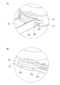
- the first claw portion 310 has a predetermined length along the rotation direction of the second member 35, as shown in FIG. 7 (A). The first claw portion 310 is disengaged from the first engaging portion 360 when the second member 35 is relatively rotated with respect to the main body portion 10 while being engaged with the first engaging portion 360.
- the second claw portion 320 has a predetermined length along the rotation direction of the second member 35, as shown in FIG. 7 (B).
- the second claw portion 320 is disengaged from the second engaging portion 370 when the second member 35 is relatively rotated with respect to the main body portion 10 while being engaged with the second engaging portion 370.
- the second claw portion 320 is formed at a position different from the first claw portion 310 in the circumferential direction of the second member 35.
- the third claw portion 330 projects from the second tubular body 37 of the second member 35 toward the lower side (the side opposite to the side where the knob portion 39 is arranged). .. As shown in FIGS. 1 (A) and 1 (B), the third claw portion 330 is formed on the main body portion 10 while the second member 35 is rotating relative to the first member 31. It also slides along the third engaging portion 380.
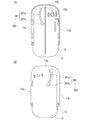
- the third engaging portion 380 has an arc shape extending along the rotation direction of the second member 35. It is a hole 381 that is cut out. The hole portion 381 penetrates the mounting surface 12 and the bottom surface (the surface on the side arranged on the body surface of the living body) of the bottom portion 11 of the main body portion 10.
- 9A is a plan view of the main body portion 10 viewed from the mounting surface 12 side
- FIG. 9B is a plan view of the main body portion 10 viewed from the bottom surface side.
- the hole 381 is formed in the first portion 381a that guides the sliding movement of the second member 35 with respect to the bottom portion 11, and in the end portion of the first portion 381a.
- the second portion 381b that allows the third claw portion 330 to be removed from the hole 381.
- the second portion 381b is formed wider than the first portion 381a. Therefore, the third claw portion 330 is prevented from being separated from the first portion 381a while slidingly moving the first portion 381a, and reaches the second portion 381b when the third claw portion 330 reaches the second portion 381b. It is possible to disconnect from 381.
- the housing 30 and the main body portion 10 are connected via the guide portion 300 (each claw portion 310, 320, 330 and each engagement portion 360, 370, 380). Then, the housing 30 and the main body 10 are connected by the second member 35 of the housing 30 when the main body 10 and the first holding portion 130 (see FIG. 3) of the puncture mechanism 110 are connected. It is released by further rotating relative to the part 10. As a result, the user fixes the first holding portion 130 of the puncture mechanism 110 to the main body 10 by performing a series of simple operations of rotating the second member 35 of the housing 30 relative to the main body 10. The disconnection of the housing 30 and the main body 10 can be continuously performed.
- the safety cap 40 restricts the movement of the locking projection 143 of the second holding part 140 and the second holding part 140 by the key hole 39c, the relative rotation of the second member 35 is restricted, and the guide part is prevented.
- the claws 310, 320, 330 of 300 are in a state of being engaged with the respective engaging portions 360, 370, 380, and it is possible to prevent the connection between the main body 10 and the housing 30 from being accidentally released.
- the user prepares the puncture device 100 and attaches the puncture device 100 to the body surface using the attachment portion 16 provided on the main body 10.
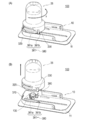
- the user moves the second member 35 of the housing 30 with the arrow r while the claws 310, 320, 330 are engaged with the engaging parts 360, 370, 380.
- FIG. 1B the second member 35 of the housing 30 is guided (held) by the three claws 310, 320, 330 when rotating. Therefore, it is possible to prevent the second member 35 of the housing 30 from rotating in a tilted state.
- the housing 30 can be rotated in parallel with the bottom portion 11 of the main body portion 10, and the puncture needle 20 projects while the second member 35 of the housing 30 is lifted from the main body portion 10 to perform the first holding. It is possible to prevent the portion 130 from being attached to the main body portion 10 in a tilted state or being left in a state where the fitting portion 150 is not sufficiently fixed.
- the user can move the first claw portion 310 out of the first engaging portion 360 and the second claw portion 320 out of the second engaging portion 370.
- the second member 35 of the housing 30 can be removed from the main body portion 10.
- the puncture of the puncture needle 20 by the puncture mechanism 110 is performed when the second member 35 of the housing 30 rotates to a predetermined position and the locking projection 143 and the key hole 39c overlap each other (see FIG. 5C). ),
- the puncture needle 20 is protruded from the insertion hole 12a of the main body 10 to be implemented.
- the user uses the lancing device 100 to indwell the cannula 21 in the living body, and then removes the housing 30 from the main body 10. Next, the user attaches the liquid delivery mechanism 200 to the main body 10 as shown in FIG.
- the first holding portion 130 is left in the main body portion 10 with the cannula 21 being introduced into the living body.
- the dose can be sent into the living body via the connection port 132 of the first holding unit 130.
- the liquid feeding mechanism 200 is not particularly limited as long as it is configured to be able to feed a predetermined dose into the cannula 21, but, for example, as shown in FIG. 10, members required for liquid feeding operation are driven.
- a reuse unit 210 including a drive mechanism 211 for generating a driving force, a disposable unit 220 that can be connected and separated from the reuse unit 210, and an insulin-filled drug solution storage unit 221 disposed in the disposable unit 220 are used. can do.
- the user can arrange and connect the liquid feeding mechanism 200 on the mounting surface 12 of the main body 10 in a state where the reuse part 210 and the disposable part 220 are connected.
- the puncture device 100 has a main body 10 that can be mounted on the surface of a living body, a puncture needle 20 including a cannula 21 and an inner needle 22 inserted into the cannula 21, and a casing that houses the puncture needle 20.
- the body 30 and the puncture mechanism 110 that is provided in the housing 30 and that performs the puncturing operation to introduce the puncture needle 20 into the living body according to the relative rotation of the housing 30 with respect to the main body unit 10, and the puncture needle 20 are the main body.
- the fixing mechanism 120 for fixing the cannula 21 to the main body portion 10 and the housing 30 so that the housing 30 rotates in parallel to the bottom portion 11 mounted on the living body surface of the main body portion 10.
- a guide portion 300 for guiding the rotation of the.
- the puncture device 100 configured as described above, when the housing 30 provided with the puncture mechanism 110 is rotated relative to the main body 10 mountable on the surface of the living body, the main body is guided by the guide portion 300.
- the housing 30 can be rotated parallel to the bottom portion 11 of the portion 10. Therefore, the user who uses the lancing device 100 can more reliably perform the insertion of the cannula into the living body by a simpler operation.
- the guide unit 300 also supports the housing 30 with respect to the main body 10 at three or more points when the housing 30 rotates relative to the main body 10. Therefore, when the user rotates the housing 30, the user can preferably prevent the housing 30 from being obliquely arranged or being operated unsteadily in rotation.
- the housing 30 is rotatable relative to the first member 31 that accommodates the puncture mechanism 110 and the first member 31 with the protruding direction of the puncture needle 20 as an axis when the first member 31 is covered.
- a second member 35 attached to the.
- the main body portion 10 has a side wall portion 13 rising from the bottom portion 11.
- the guide part 300 includes a first claw part 310, a second claw part 320, and a third claw part 330 formed on the second member 35, and a first claw part 310 formed on the side wall part 13 and engageable with the first claw part 310.
- the guide portion 300 rotates the second member 35 of the housing 30 in a state where the claw portions 310, 320, 330 and the engaging portions 360, 370, 380 are engaged with each other, so that the second member is rotated. 35 can be rotated parallel to the bottom 11 of the body 10.
- the third engaging portion 380 is a hole portion 381 that is cut out in an arc shape and extends along the rotation direction of the second member 35. Therefore, the user can support the second member 35 with respect to the main body portion 10 by engaging the third claw portion 330 with the hole portion 381 formed in the bottom portion 11 of the main body portion 10. ..
- the hole portion 381 is formed at the first portion 381a that guides the sliding movement of the second member 35 with respect to the bottom portion 11, and the third claw portion 330 can be removed from the hole portion 381 at the end portion of the first portion 381a. And a second portion 381b. Therefore, the user can guide the sliding movement of the second member 35 through the hole 381, and easily interlock with the rotation of the second member 35 so that the third claw portion 330 can be easily pulled out from the hole 381. be able to.
- the first portion 381a may have a step structure that facilitates sliding movement of the third claw portion 330.
- This step structure may be engaged with the third claw portion 330, or the third claw portion 330 may be inserted into the bag-shaped structure to form a slideable passage.
- the third claw 330 is caught on the double-sided tape or the skin. It is possible to make it a structure that is easy to rotate.
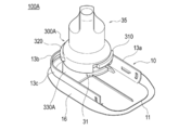
- ⁇ Modification> 11 to 13 show a puncture device 100A according to a modification.
- the first member 31 of the main body 10 is provided with the convex portion 330A which is a constituent member of the guide portion 300A.
- a support portion 380A capable of supporting the convex portion 330A is formed on the inner surface of the third side wall 13c of the side wall portion 13 of the main body portion 10.
- the claws 310 and 320 and the engaging portions 360 and 370 are the same as those in the above-described embodiment.
- the convex portion 330A has a flange portion 333 formed on the end portion 331 arranged on the support portion 380A side.
- the support portion 380A has a regulation portion 381c that comes into contact with the flange portion 333 and regulates the rotation of the convex portion 330A.
- the restriction portion 381c is configured to be able to contact the flange portion 333 over a predetermined length.
- the user When rotating the second member 35 of the housing 30, the user can fix and support the first member 31 with respect to the main body unit 10 until the rotation operation is completed. Therefore, it is possible to prevent the first member 31 from being obliquely arranged or rising. Therefore, the housing 30 can be rotated parallel to the bottom 11 of the main body 10.
- the guide portion 300A according to the modification can be provided in the puncture device 100A without forming the hole portion 381 in the main body portion 10. Therefore, it is possible to suppress the influence on the arrangement pattern of the attachment portions 16 arranged on the bottom surface of the bottom portion 11 of the main body portion 10 and at the same time prevent the strength of the bottom portion 11 from decreasing.
- the puncture device according to the present invention has been described above through the embodiments.
- the present invention is not limited to the contents described in the specification, and can be appropriately modified based on the description in the claims. is there.
- a drug solution administration device is given as an example of application of the puncture device according to the present invention, but medical equipment to which the puncture device is applied is not particularly limited.
- the medical device may be, for example, an inspection device including an inspection unit that is inserted into the living body.
- 1 drug administration device 10 body, 11 bottom, 13 Side wall, 13a first side wall, 13b second sidewall, 13c Third sidewall, 20 puncture needle, 21 cannula, 22 inner needle, 30 housings, 31 First member, 35 Second member, 100, 100A lancing device, 110 puncture mechanism, 120 fixing mechanism, 200 liquid transfer mechanism, 210 reuse department, 220 disposable part, 300, 300A guide part, 310 the first claw portion, 320 second claw portion, 330 third claw portion, 330A convex part, 333 flange part, 360 first engaging portion, 370 second engaging portion, 380 Third engagement portion, 380A support, 381 holes, 381a first part, 381b second part, 381c Regulatory department.
Landscapes
- Health & Medical Sciences (AREA)
- Vascular Medicine (AREA)
- Engineering & Computer Science (AREA)
- Anesthesiology (AREA)
- Biomedical Technology (AREA)
- Heart & Thoracic Surgery (AREA)
- Hematology (AREA)
- Life Sciences & Earth Sciences (AREA)
- Animal Behavior & Ethology (AREA)
- General Health & Medical Sciences (AREA)
- Public Health (AREA)
- Veterinary Medicine (AREA)
- Infusion, Injection, And Reservoir Apparatuses (AREA)
Abstract
【課題】操作性に優れるとともに生体へのカニューレの挿入をより確実に実施することができる穿刺装置を提供する。 【解決手段】穿刺装置100は、生体表面に装着可能な本体部10と、カニューレ21、およびカニューレ内に挿入された内針22を備える穿刺針20と、穿刺針を収容する筐体30と、前記筐体内に設けられ、本体部に対する筐体の相対的な回転に伴って穿刺針を生体内に導入する穿刺動作を行う穿刺機構110と、穿刺針が本体部から突出した状態において、カニューレを本体部に固定する固定機構120と、本体部の生体表面に装着される底部11に対して筐体が平行に回転するように筐体の回転をガイドするガイド部300と、を有する。
Description
本発明は、穿刺装置に関する。
従来、インスリンなどの薬液を生体内へ投与するために使用される装置として、使用者の皮膚に付着させて用いられる携帯型の投与装置が知られている。例えば、特許文献1には、生体に装着可能なクレードルと、内針とカニューレとからなる二重構造の穿刺具と、カニューレを生体に挿入するための挿入器と、を有する投与装置が記載されている。投与装置の挿入器は、クレードルから穿刺具を突出させる方向に向けて穿刺具に付勢力を付与する付勢部材を備えている。
上述した投与装置では、挿入器を使用して穿刺具を生体に穿刺した後、生体に装着されたクレードル上の突起にカニューレを係合させた状態で挿入器をクレードルから取り外す。その後、所定の薬液等が貯蔵された貯蔵部をクレードルに装着することにより、カニューレを介して生体内へ薬液を送出する。
上述したカニューレと突起との係合は、挿入器によって穿刺具が生体に穿刺される際、穿刺具に付与される付勢力の一部を利用してカニューレが突起を乗り越えることによってなされる。突起を乗り越える過程で、カニューレは、突起と接触することに起因して突起からも力を受けるため、皮膚に対して垂直な姿勢に維持されるとは必ずしも言えない。
また、使用者が挿入器の操作を誤ると、挿入器がクレードル上で安定した姿勢で動作せず、クレードルに対する挿入器の固定(嵌合)が十分になされない可能性がある。
本発明の目的は、操作性に優れるとともに生体へのカニューレの挿入をより確実に実施することができる穿刺装置を提供することにある。
上記目的を達成するための本発明に係る穿刺装置は、生体表面に装着可能な本体部と、カニューレ、および前記カニューレ内に挿入された内針を備える穿刺針と、前記穿刺針を収容する筐体と、前記筐体内に設けられ、前記本体部に対する前記筐体の相対的な回転に伴って前記穿刺針を生体内に導入する穿刺動作を行う穿刺機構と、前記穿刺針が前記本体部から突出した状態において、前記カニューレを前記本体部に固定する固定機構と、前記本体部の前記生体表面に装着される底部に対して前記筐体が平行に回転するように前記筐体の回転をガイドするガイド部と、を有する。
本発明に係る穿刺装置によれば、穿刺機構が設けられた筐体を生体表面に装着可能な本体部に対して相対的に回転させる際、ガイド部により、本体部の底部に対して筐体を平行に回転させることができる。そのため、穿刺装置を使用する使用者は、より簡単な操作で生体内へのカニューレの挿入をより確実に実施することができる。
以下、添付した図面を参照しながら、本発明の実施形態を説明する。なお、以下の記載は特許請求の範囲に記載される技術的範囲や用語の意義を限定するものではない。また、図面の寸法比率は説明の都合上誇張されており、実際の比率とは異なる場合がある。
図1、図2は本実施形態に係る穿刺装置100の使用例を示す斜視図であり、図3~図9は本実施形態に係る穿刺装置100の各部の構成を示す図であり、図10は本実施形態に係る医療機器(薬液投与装置)1を示す分解斜視図である。
本実施形態に係る穿刺装置100は、薬液(例えば、インスリン等)などの投与物を送出するための所定の送液機構200とともに用いることができる(図10を参照)。穿刺装置100および送液機構200は、薬液を生体内へ投与する薬液投与装置1を構成することができる。
図1~図3に示すように、穿刺装置100は、概説すると、生体表面に装着可能な本体部10と、カニューレ21およびカニューレ21内に挿入された内針22を備える穿刺針20と、穿刺針20を収容する筐体30と、筐体30内に設けられ、本体部10に対する筐体30の相対的な回転に伴って穿刺針20を生体内に導入する穿刺動作を行う穿刺機構110と、穿刺針20が本体部10から突出した状態において、カニューレ21を本体部10に固定する固定機構120(図6を参照)と、本体部10の生体表面に装着される底部11に対して筐体30が平行に回転するように筐体30の回転をガイドするガイド部300と、を有している。
穿刺装置100は、図3に示すように、本体部10に接続された筐体30にセーフティキャップ40が取り付けられた状態において提供される。本体部10は、生体においてカニューレ21を留置したい所望の箇所に付着させることができる。セーフティキャップ40を取り外すと、筐体30は、本体部10に対して穿刺針20の突出方向Zを軸にして相対的に回転可能な状態になる。本体部10に対して筐体30を相対的に回転させる動作に連動して、穿刺針20の突出と、本体部10に対するカニューレ21の固定と、本体部10と筐体30との接続の解除が連続的に行われる。
まず、穿刺装置100の全体構成について説明する。
図1~図3に示すように、本体部10は、生体に装着可能な付着部16と、カニューレ21を介して所定の投与物を生体内へ送出する送液機構200が装着可能な装着部18と、を有するクレードルとして構成されている。本体部(クレードル)10の各部を構成する材料には、例えば、公知の樹脂材料や金属材料を使用することができる。
本体部10の付着部16は、装置を使用する際に生体の皮膚表層に向かい合わせて配置される底面に設けられている。付着部16は、両面テープや接着剤等により構成することができる。また、付着部16は使用前に剥離紙等により覆うことができる。
図3に示すように、本体部10の装着部18は、平面状に形成された載置面12が形成された底部11と、底部11から立ち上がる側壁部13と、を有している。載置面12上には、本体部10から筐体30を取り外した後の状態において送液機構200を配置することができる(図2(B)を参照)。載置面12には、穿刺針20を挿通可能な挿通穴12a(図9(A)を参照)が形成されている。
本体部10の側壁部13は、載置面12の外周に沿って一の方向に延在する第1の側壁13aと、載置面12の外周に沿って一の方向に交差する他の方向に延在する第2の側壁13bと、第1の側壁13aに対向して載置面12の外周に沿って延在する第3の側壁13cと、を有する。
カニューレ21および内針22は、例えば、内部に流路が形成された公知の中空針によって構成することができる。カニューレ21および内針22の外径、内径、長さ寸法等は、生体への穿刺が可能であればよく、使用される目的に応じた任意のものを使用することができる。
筐体30は、図3、図4(A)、図4(B)に示すように、穿刺機構110を収容する第1部材31と、第1部材31を覆った状態において穿刺針20の突出方向Zを軸にして第1部材31に対して相対的に回転自在に取り付けられる第2部材35と、を有する。
第1部材31は、図3、図4(B)に示すように、略円筒形状の筒体32と、筒体32の外周面から延出するとともに、第1部材31が本体部10に接続されたときに装着部18の載置面12に当接する脚部33と、を有する。筒体32の外周面は、穿刺針20の突出方向Zを軸にした第1部材31に対する第2部材35の回転をガイドするガイド面を形成している。
脚部33は、図4(B)、図8に示すように、第1部材31が装着部18に接続された状態において装着部18の第1の側壁13aが挿入される第1の凹部33aと、第1部材31が装着部18に接続された状態において装着部18の第2の側壁13bが挿入される第2の凹部33bと、を備えている。第1の凹部33aに第1の側壁13aが挿入されることによって、第1の側壁13aの延在方向に交差する方向において第1部材31の移動が規制される。また、第2の凹部33bに第2の側壁13bが挿入されることによって、第2の側壁13bの延在方向に交差する方向において第1部材31の移動が規制される。
第2部材35は、図4(A)、図7に示すように、略円筒形状の第1の筒体36と、第1の筒体36の外径よりも大きな外径を備える第2の筒体37と、第1の筒体36と第2の筒体37とを接続する第3の筒体38と、第1の筒体36および第2の筒体37に対して穿刺針20の突出方向Zを軸にした回転力を付与するツマミ部39と、を有する。使用者は、ツマミ部39に対して回転力を付与することによって、第2部材35の第1の筒体36の内周面を第1部材31の筒体32の外周面によりガイドしながら、第2部材35を第1部材31に対して相対的に回転させることができる。
<穿刺機構>
穿刺機構110は、図3に示すように、カニューレ21を保持する第1保持部130および内針22を保持する第2保持部140を含む穿刺針保持部111と、穿刺針20を本体部10から突出させる突出方向Zの付勢力を穿刺針保持部111に付与する付勢部材112と、を有する。
穿刺機構110は、図3に示すように、カニューレ21を保持する第1保持部130および内針22を保持する第2保持部140を含む穿刺針保持部111と、穿刺針20を本体部10から突出させる突出方向Zの付勢力を穿刺針保持部111に付与する付勢部材112と、を有する。
穿刺針保持部111は、カニューレ21を保持する第1保持部130および内針22を保持する第2保持部140を有する。穿刺針保持部111は、穿刺針20の突出方向Zにおいて移動可能な状態で筐体30に収容される。
第1保持部130は、図3に示すように、カニューレ21の一部を突出させた状態で保持する基部131と、第1保持部130の外部から薬液を供給する送液管が挿入される内腔を備える接続ポート132を有している。また、第1保持部130は、接続ポート132を覆うようにして取り付けられるキャップ(図示省略)と、基部131においてカニューレ21を保持する側とは異なる側に取り付けられた蓋部材(図示省略)と、基部131と蓋部材との間に設けられたシール部材(図示省略)と、を有している。
第2保持部140は、図3に示すように、内針22を保持する基部141を有している。基部141は、第2保持部140を本体部10から引き上げる動作に伴って内針22をカニューレ21から抜去する。
付勢部材112は、筐体30内において穿刺針20の突出方向Zに付勢力を付与する。図1(A)に示すように、筐体30が本体部10に接続された状態において、穿刺針20の突出方向Z、およびその逆方向における筐体30の移動は規制されている。そのため、付勢部材112が付与する付勢力によって筐体30が穿刺針20の突出方向Z、およびその逆方向に移動することが規制される。一方で、穿刺針保持部111は、筐体30に収容された状態において穿刺針20の突出方向Zに移動可能に配置される。そのため、穿刺針保持部111は、付勢部材112から付与される付勢力によって穿刺針20の突出方向Zに向かって移動する。その結果、穿刺針20は、本体部10の載置面12に形成された挿通穴12aを通過して本体部10から突出することができる。
具体的には、図5(A)に示すように、第2部材35のツマミ部39の頂部は、穿刺針保持部111の第2保持部140と当接して、付勢部材112による第2保持部140の移動を規制する。図5(B)に示すように、第2部材35を回転させると、ツマミ部39に形成された鍵穴39cが第2保持部140のロック用突起143と位置合わせされる。ロック用突起143と鍵穴39cの位置が重なると、付勢部材112による付勢力が開放されて、図5(C)に示すように、第2保持部140が突出方向Zへ移動し、内針22が本体部10の挿通穴12aに向けて突出される。
<固定機構>
固定機構120は、図6に示すように、第1保持部130が本体部10に対して突出方向Zとは異なる方向に相対的に移動する動作(第2部材35の回転動作)に伴って当該第1保持部130を当該本体部10に係合する嵌合部150を備える。嵌合部150は、第1保持部130側に設けられる第1嵌合部151と、本体部10側に設けられ、第1嵌合部151に嵌合する第2嵌合部152と、を備える。
固定機構120は、図6に示すように、第1保持部130が本体部10に対して突出方向Zとは異なる方向に相対的に移動する動作(第2部材35の回転動作)に伴って当該第1保持部130を当該本体部10に係合する嵌合部150を備える。嵌合部150は、第1保持部130側に設けられる第1嵌合部151と、本体部10側に設けられ、第1嵌合部151に嵌合する第2嵌合部152と、を備える。
第1保持部130と本体部10とは、穿刺針20の突出方向Zを軸に筐体30が本体部10に対して相対的に回転する動作に連動して第1保持部130が本体部10に対して相対的に回転した際、各嵌合部151、152を介して相互に嵌合する。
<ガイド部>
ガイド部300は、筐体30が本体部10に対して相対的に回転する際、筐体30を本体部10に対して3点以上で支持するように構成している。
ガイド部300は、筐体30が本体部10に対して相対的に回転する際、筐体30を本体部10に対して3点以上で支持するように構成している。
本実施形態では、ガイド部300は、図7(A)、図7(B)、図9(A)、図9(B)に示すように、第2部材35に形成された第1爪部310、第2爪部320、および第3爪部330と、本体部10に形成された第1係合部360、第2係合部370、および第3係合部380と、を有している。
図4(A)に示すように、第1爪部310、第2爪部320、および第3爪部330は、第2部材35の第2の筒体37に形成されている。
図3、図9(A)、図9(B)に示すように、第1係合部360は、側壁部13の第1の側壁13aに形成されている。第2係合部370は、側壁部13の第2の側壁13bに形成されている。第3係合部380は、底部11に形成されている。
第1係合部360は、図7(A)に示すように、第1爪部310が係合可能な孔部で構成している。第2係合部370は、図7(B)に示すように第2爪部320が係合可能な孔部で構成している。図1(A)、図9(A)、図9(B)に示すように、第3係合部380は、第3爪部330が係合可能な孔部381で構成している。
第1爪部310は、図7(A)に示すように、第2部材35の回転方向に沿って所定の長さを有している。第1爪部310は、第1係合部360に係合した状態において、第2部材35が本体部10に対して相対的に回転した際、第1係合部360から離脱する。
第2爪部320は、図7(B)に示すように、第2部材35の回転方向に沿って所定の長さを有している。第2爪部320は、第2係合部370に係合した状態において、第2部材35が本体部10に対して相対的に回転した際、第2係合部370から離脱する。第2爪部320は、第2部材35の周方向において、第1爪部310と異なる位置に形成されている。
第3爪部330は、図4(A)に示すように、第2部材35の第2の筒体37から下方側(ツマミ部39が配置された側と反対側)に向けて突出している。図1(A)、図1(B)に示すように、第3爪部330は、第2部材35が第1部材31に対して相対的に回転している間、本体部10に形成された第3係合部380に沿ってスライド移動する。
図1(A)、図1(B)、図9(A)、図9(B)に示すように、第3係合部380は、第2部材35の回転方向に沿って延びる円弧状に切り欠かれた孔部381である。孔部381は、本体部10の底部11の載置面12と底面(生体の体表面に配置される側の面)とを貫通している。なお、図9(A)は載置面12側から見た本体部10の平面図であり、図9(B)は底面側から見た本体部10の平面図である。
孔部381は、図9(A)、図9(B)に示すように、底部11に対する第2部材35のスライド移動をガイドする第1部位381aと、第1部位381aの端部に形成され孔部381からの第3爪部330の取り外しを可能にする第2部位381bと、を有している。
第2部位381bは、第1部位381aよりも幅広に形成されている。そのため、第3爪部330は、第1部位381aをスライド移動している間は、第1部位381aからの離脱が防止され、第2部位381bに到達すると、第2部位381bを介して孔部381から離脱することができる。
上記のように、筐体30と本体部10は、ガイド部300(各爪部310、320、330および各係合部360、370、380)を介して接続される。そして、筐体30と本体部10との接続は、本体部10と穿刺機構110の第1保持部130(図3を参照)とが接続した状態において、筐体30の第2部材35が本体部10に対してさらに相対的に回転することによって解除される。これにより、使用者は、本体部10に対して筐体30の第2部材35を相対的に回転させる簡便な一連の操作によって、本体部10への穿刺機構110の第1保持部130の固定と、筐体30および本体部10の接続の解除と、を連続して行うことができる。また、セーフティキャップ40によって第2保持部140のロック用突起143と鍵穴39cによる第2保持部140の移動が規制されている間は、第2部材35の相対的な回転が規制され、ガイド部300の各爪部310、320、330が各係合部360、370、380に係合した状態であり、本体部10と筐体30との接続が不用意に解除されることを防止できる。
<穿刺装置の操作例>
次に、図1(A)、図1(B)、図2(A)、図2(B)を参照して、本実施形態に係る穿刺装置100の操作例を説明する。
次に、図1(A)、図1(B)、図2(A)、図2(B)を参照して、本実施形態に係る穿刺装置100の操作例を説明する。
使用者は、穿刺装置100を準備し、本体部10に設けられた付着部16を使用して、穿刺装置100を体表面に装着する。使用者は、図1(A)に示すように、各爪部310、320、330が各係合部360、370、380に係合した状態で、筐体30の第2部材35を矢印rで示すように回転させる。図1(B)に示すように、筐体30の第2部材35は、回転する際、3つの爪部310、320、330によりガイド(保持)される。そのため、筐体30の第2部材35が傾いた状態で回転することを防止できる。したがって、本体部10の底部11に対して筐体30を平行に回転させることができ、筐体30の第2部材35が本体部10から浮き上がった状態で穿刺針20が突出して、第1保持部130が傾いた状態で本体部10に装着されたり、嵌合部150の固定が不十分な状態で留置されたりすることを防止できる。
使用者は、図2(A)、図2(B)に示すように、第1爪部310が第1係合部360から抜け出る位置、第2爪部320が第2係合部370から抜け出る位置、および第3爪部330が孔部381の第2部位381bに到達すると、筐体30の第2部材35を本体部10から取り外すことができる。なお、穿刺機構110による穿刺針20の穿刺は、筐体30の第2部材35が所定の位置まで回転し、ロック用突起143と鍵穴39cの位置が重なった際に(図5(C)を参照)、穿刺針20が本体部10の挿通穴12aから突出して実施される。
使用者は、穿刺装置100を使用してカニューレ21を生体に留置した後、本体部10から筐体30を取り外す。次に、使用者は、図10に示すように、本体部10に送液機構200を装着させる。
前述したように、本体部10から筐体30を取り外した後は、カニューレ21が生体内に導入された状態で第1保持部130が本体部10に残される。所定の投与物を投与するための送液機構200を第1保持部130に接続させることで、第1保持部130の接続ポート132を介して生体内へ投与物を送り込むことができる。
送液機構200としては、カニューレ21へ所定の投与物を送り込むことが可能に構成されていれば特に制限はないが、例えば、図10に示すように、送液動作に必要な部材を駆動させる駆動力を生じさせる駆動機構211等を含むリユース部210およびリユース部210と接続分離可能なディスポーザブル部220と、ディスポーザブル部220に配置されたインスリンが充填された薬液貯蔵部221等を有するものを使用することができる。使用者は、リユース部210とディスポーザブル部220とを接続した状態で、本体部10の載置面12上に送液機構200を配置および接続することができる。
以上、本実施形態に係る穿刺装置100は、生体表面に装着可能な本体部10と、カニューレ21およびカニューレ21内に挿入された内針22を備える穿刺針20と、穿刺針20を収容する筐体30と、筐体30内に設けられ、本体部10に対する筐体30の相対的な回転に伴って穿刺針20を生体内に導入する穿刺動作を行う穿刺機構110と、穿刺針20が本体部10から突出した状態において、カニューレ21を本体部10に固定する固定機構120と、本体部10の生体表面に装着される底部11に対して筐体30が平行に回転するように筐体30の回転をガイドするガイド部300と、を有する。
上記のように構成された穿刺装置100によれば、穿刺機構110が設けられた筐体30を生体表面に装着可能な本体部10に対して相対的に回転させる際、ガイド部300により、本体部10の底部11に対して筐体30を平行に回転させることができる。そのため、穿刺装置100を使用する使用者は、より簡単な操作で生体内へのカニューレの挿入をより確実に実施することができる。
また、ガイド部300は、筐体30が本体部10に対して相対的に回転する際、筐体30を本体部10に対して3点以上で支持する。そのため、使用者は、筐体30を回転させる際、筐体30が斜めに配置されたり、回転が安定せずに操作されたりすることを好適に防止できる。
また、筐体30は、穿刺機構110を収容する第1部材31と、第1部材31を覆った状態において穿刺針20の突出方向を軸にして第1部材31に対して相対的に回転自在に取り付けられる第2部材35と、を有している。本体部10は、底部11から立ち上がる側壁部13を有している。ガイド部300は、第2部材35に形成された第1爪部310、第2爪部320、および第3爪部330と、側壁部13に形成され第1爪部310が係合可能な第1係合部360、側壁部13に形成され第2爪部320が係合可能な第2係合部370、および底部11に形成され第3爪部330が係合可能な第3係合部380を有する。そのため、ガイド部300は、各爪部310、320、330と各係合部360、370、380とが係合された状態で筐体30の第2部材35を回転させることにより、第2部材35を本体部10の底部11に対して平行に回転させることができる。
また、第3係合部380は、第2部材35の回転方向に沿って延びる円弧状に切り欠かれた孔部381である。そのため、使用者は、第3爪部330を本体部10の底部11に形成された孔部381に係合させることにより、第2部材35を本体部10に対して支持させることが可能になる。
また、孔部381は、底部11に対する第2部材35のスライド移動をガイドする第1部位381aと、第1部位381aの端部に形成され孔部381からの第3爪部330の取り外しを可能にする第2部位381bと、を有している。そのため、使用者は、孔部381により第2部材35のスライド移動をガイドすることができるとともに、第2部材35の回転に連動させて、孔部381から第3爪部330を容易に抜け出させることができる。
なお、第1部位381aは第3爪部330をスライド移動しやすい段差構造となっていてもよい。この段差構造は第3爪部330と係合してもよく、袋状の構造内に第3爪部330が入れ込まれてスライド移動可能な通路となっていてもよい。このような構造とすることで、本体部10を生体表面に装着した状態で筐体30の第2部材35を回転する際であっても、第3爪部330が両面テープや皮膚に引っ掛かることがなく、回転しやすい構造とすることができる。
<変形例>
図11~図13には、変形例に係る穿刺装置100Aを示している。変形例に係る穿刺装置100Aは、本体部10の第1部材31にガイド部300Aの構成部材である凸部330Aが形成されている。また、本体部10の側壁部13の第3の側壁13cの内面には、凸部330Aを支持可能な支持部380Aが形成されている。なお、各爪部310、320、各係合部360、370は、前述した実施形態と同様である。
図11~図13には、変形例に係る穿刺装置100Aを示している。変形例に係る穿刺装置100Aは、本体部10の第1部材31にガイド部300Aの構成部材である凸部330Aが形成されている。また、本体部10の側壁部13の第3の側壁13cの内面には、凸部330Aを支持可能な支持部380Aが形成されている。なお、各爪部310、320、各係合部360、370は、前述した実施形態と同様である。
凸部330Aは、支持部380A側に配置される端部331に形成されたフランジ部333を有している。支持部380Aは、フランジ部333と当接して凸部330Aの回転を規制する規制部381cを有している。規制部381cは、所定の長さに亘ってフランジ部333と当接可能に構成している。
使用者は、筐体30の第2部材35を回転させる際、回転動作が終了するまで第1部材31を本体部10に対して固定して支持することができる。そのため、第1部材31が斜めに配置されたり、浮き上がったりすることを防止できる。したがって、筐体30を本体部10の底部11に対して平行に回転させることができる。
また、変形例に係るガイド部300Aは、本体部10に孔部381を形成することなく穿刺装置100Aに設けることが可能である。そのため、本体部10の底部11の底面に配置される付着部16の配置パターンなどへの影響を抑えると同時に、底部11の強度低下を防止することができる。
以上、実施形態を通じて本発明に係る穿刺装置を説明したが、本発明は明細書において説明した内容のみに限定されるものでなく、特許請求の範囲の記載に基づいて適宜変更することが可能である。
実施形態の説明では、本発明に係る穿刺装置の適用例として薬液投与装置を例に挙げたが、穿刺装置を適用する医療機器は特に限定されない。医療機器は、例えば、生体内に挿入される検査部を備える検査装置等であってもよい。
本出願は、2018年11月7日に出願された日本国特許出願第2018-209896号に基づいており、その開示内容は、参照により全体として引用されている。
1 薬液投与装置、
10 本体部、
11 底部、
13 側壁部、
13a 第1の側壁、
13b 第2の側壁、
13c 第3の側壁、
20 穿刺針、
21 カニューレ、
22 内針、
30 筐体、
31 第1部材、
35 第2部材、
100、100A 穿刺装置、
110 穿刺機構、
120 固定機構、
200 送液機構、
210 リユース部、
220 ディスポーザブル部、
300、300A ガイド部、
310 第1爪部、
320 第2爪部、
330 第3爪部、
330A 凸部、
333 フランジ部、
360 第1係合部、
370 第2係合部、
380 第3係合部、
380A 支持部、
381 孔部、
381a 第1部位、
381b 第2部位、
381c 規制部。
10 本体部、
11 底部、
13 側壁部、
13a 第1の側壁、
13b 第2の側壁、
13c 第3の側壁、
20 穿刺針、
21 カニューレ、
22 内針、
30 筐体、
31 第1部材、
35 第2部材、
100、100A 穿刺装置、
110 穿刺機構、
120 固定機構、
200 送液機構、
210 リユース部、
220 ディスポーザブル部、
300、300A ガイド部、
310 第1爪部、
320 第2爪部、
330 第3爪部、
330A 凸部、
333 フランジ部、
360 第1係合部、
370 第2係合部、
380 第3係合部、
380A 支持部、
381 孔部、
381a 第1部位、
381b 第2部位、
381c 規制部。
Claims (7)
- 生体表面に装着可能な本体部と、
カニューレ、および前記カニューレ内に挿入された内針を備える穿刺針と、
前記穿刺針を収容する筐体と、
前記筐体内に設けられ、前記本体部に対する前記筐体の相対的な回転に伴って前記穿刺針を生体内に導入する穿刺動作を行う穿刺機構と、
前記穿刺針が前記本体部から突出した状態において、前記カニューレを前記本体部に固定する固定機構と、
前記本体部の前記生体表面に装着される底部に対して前記筐体が平行に回転するように前記筐体の回転をガイドするガイド部と、を有する穿刺装置。 - 前記ガイド部は、前記筐体が前記本体部に対して相対的に回転する際、前記筐体を前記本体部に対して3点以上で支持する、請求項1に記載の穿刺装置。
- 前記筐体は、前記穿刺機構を収容する第1部材と、前記第1部材を覆った状態において前記穿刺針の突出方向を軸にして前記第1部材に対して相対的に回転自在に取り付けられる第2部材と、を有し、
前記本体部は、前記底部から立ち上がる側壁部を有し、
前記ガイド部は、前記第2部材に形成された第1爪部、第2爪部、および第3爪部と、前記側壁部に形成され前記第1爪部が係合可能な第1係合部、前記側壁部に形成され前記第2爪部が係合可能な第2係合部、および前記底部に形成され前記第3爪部が係合可能な第3係合部を有する、請求項2に記載の穿刺装置。 - 前記第3係合部は、前記第2部材の回転方向に沿って延びる円弧状に切り欠かれた孔部である、請求項3に記載の穿刺装置。
- 前記孔部は、前記底部に対する前記第2部材のスライド移動をガイドする第1部位と、前記第1部位の端部に形成され前記孔部からの前記第3爪部の取り外しを可能にする第2部位と、を有する請求項4に記載の穿刺装置。
- 前記筐体は、前記穿刺機構を収容する第1部材と、前記第1部材を覆った状態において前記穿刺針の突出方向を軸にして前記第1部材に対して相対的に回転自在に取り付けられる第2部材と、を有し、
前記本体部は、前記底部から立ち上がる側壁部を有し、
前記ガイド部は、前記第2部材に形成された第1爪部および第2爪部、前記第1部材に形成された凸部と、前記側壁部に形成され前記第1爪部が係合可能な第1係合部、前記側壁部に形成され前記第2爪部が係合可能な第2係合部、および前記側壁部に形成され前記凸部を支持可能な支持部と、を有する、請求項2に記載の穿刺装置。 - 前記凸部は、前記支持部側に配置される端部に形成されたフランジ部を有し、
前記支持部は、前記フランジ部と当接して前記凸部の回転を規制する規制部を有する、請求項6に記載の穿刺装置。
Priority Applications (1)
| Application Number | Priority Date | Filing Date | Title |
|---|---|---|---|
| JP2020556085A JP7429646B2 (ja) | 2018-11-07 | 2019-11-05 | 穿刺装置 |
Applications Claiming Priority (2)
| Application Number | Priority Date | Filing Date | Title |
|---|---|---|---|
| JP2018-209896 | 2018-11-07 | ||
| JP2018209896 | 2018-11-07 |
Publications (1)
| Publication Number | Publication Date |
|---|---|
| WO2020095907A1 true WO2020095907A1 (ja) | 2020-05-14 |
Family
ID=70611498
Family Applications (1)
| Application Number | Title | Priority Date | Filing Date |
|---|---|---|---|
| PCT/JP2019/043319 Ceased WO2020095907A1 (ja) | 2018-11-07 | 2019-11-05 | 穿刺装置 |
Country Status (2)
| Country | Link |
|---|---|
| JP (1) | JP7429646B2 (ja) |
| WO (1) | WO2020095907A1 (ja) |
Citations (2)
| Publication number | Priority date | Publication date | Assignee | Title |
|---|---|---|---|---|
| US20130102965A1 (en) * | 2010-06-21 | 2013-04-25 | Roche Diagnostics International Ag | Device for inserting an insertion member, or a soft member, into body tissue |
| WO2017134966A1 (ja) * | 2016-02-04 | 2017-08-10 | テルモ株式会社 | 穿刺装置およびカニューレの留置方法 |
-
2019
- 2019-11-05 JP JP2020556085A patent/JP7429646B2/ja active Active
- 2019-11-05 WO PCT/JP2019/043319 patent/WO2020095907A1/ja not_active Ceased
Patent Citations (2)
| Publication number | Priority date | Publication date | Assignee | Title |
|---|---|---|---|---|
| US20130102965A1 (en) * | 2010-06-21 | 2013-04-25 | Roche Diagnostics International Ag | Device for inserting an insertion member, or a soft member, into body tissue |
| WO2017134966A1 (ja) * | 2016-02-04 | 2017-08-10 | テルモ株式会社 | 穿刺装置およびカニューレの留置方法 |
Also Published As
| Publication number | Publication date |
|---|---|
| JP7429646B2 (ja) | 2024-02-08 |
| JPWO2020095907A1 (ja) | 2021-09-30 |
Similar Documents
| Publication | Publication Date | Title |
|---|---|---|
| JP4509556B2 (ja) | 皮下注入セットを配置するためのインジェクタ器具 | |
| CN101500627B (zh) | 套管和输送装置 | |
| JP5269268B2 (ja) | フィードバック信号伝達手段を備えた薬剤送達装置 | |
| TWI421110B (zh) | 藥物輸送裝置 | |
| JP5722992B2 (ja) | 薬剤送出装置 | |
| JP5331896B2 (ja) | 薬剤送達装置 | |
| JP2008543500A (ja) | 医薬品注射用の器具及び方法 | |
| EP2554152A1 (en) | Connector and connector assembly | |
| CN103025374A (zh) | 用于预装填注射器的安全装置、注射装置和注射套件 | |
| JP2019504750A (ja) | 注入セットおよび挿入器アセンブリ | |
| JP2009511177A (ja) | 医薬品注射用の器具 | |
| CA2642440A1 (en) | Packing for injection device | |
| WO2020138193A1 (ja) | 薬剤投与デバイス、及び薬剤投与システム | |
| CN101795720A (zh) | 药液注入器具 | |
| JP2009507583A (ja) | ハンドル内に針保護装置を備えた挿入ヘッド | |
| JP6431855B2 (ja) | 薬液充填ユニット及び充填アダプタ | |
| JP2022546840A (ja) | 格納式シールド付きペンニードル | |
| WO2013154049A1 (ja) | ロック機構付きオスコネクタ | |
| JP2022521988A (ja) | 針カバー付きの自動注射器 | |
| JP2011045537A (ja) | 挿入装置用補助器具 | |
| EP3542772B1 (en) | Drug solution filling unit, drug solution filling set, and filling adapter | |
| JP2016154599A (ja) | 薬液投与装置 | |
| JP6763890B2 (ja) | 穿刺装置 | |
| TW201737956A (zh) | 輸送裝置 | |
| JP6251064B2 (ja) | 穿刺ユニット及び薬液投与ユニット |
Legal Events
| Date | Code | Title | Description |
|---|---|---|---|
| 121 | Ep: the epo has been informed by wipo that ep was designated in this application |
Ref document number: 19883057 Country of ref document: EP Kind code of ref document: A1 |
|
| ENP | Entry into the national phase |
Ref document number: 2020556085 Country of ref document: JP Kind code of ref document: A |
|
| NENP | Non-entry into the national phase |
Ref country code: DE |
|
| 122 | Ep: pct application non-entry in european phase |
Ref document number: 19883057 Country of ref document: EP Kind code of ref document: A1 |