WO2020095645A1 - プログラム更新システム及び更新処理プログラム - Google Patents
プログラム更新システム及び更新処理プログラム Download PDFInfo
- Publication number
- WO2020095645A1 WO2020095645A1 PCT/JP2019/040791 JP2019040791W WO2020095645A1 WO 2020095645 A1 WO2020095645 A1 WO 2020095645A1 JP 2019040791 W JP2019040791 W JP 2019040791W WO 2020095645 A1 WO2020095645 A1 WO 2020095645A1
- Authority
- WO
- WIPO (PCT)
- Prior art keywords
- ecu
- program
- vehicle
- general
- update
- Prior art date
- Legal status (The legal status is an assumption and is not a legal conclusion. Google has not performed a legal analysis and makes no representation as to the accuracy of the status listed.)
- Ceased
Links
Images

Classifications
-
- G—PHYSICS
- G06—COMPUTING OR CALCULATING; COUNTING
- G06F—ELECTRIC DIGITAL DATA PROCESSING
- G06F8/00—Arrangements for software engineering
- G06F8/60—Software deployment
- G06F8/65—Updates
-
- B—PERFORMING OPERATIONS; TRANSPORTING
- B60—VEHICLES IN GENERAL
- B60R—VEHICLES, VEHICLE FITTINGS, OR VEHICLE PARTS, NOT OTHERWISE PROVIDED FOR
- B60R16/00—Electric or fluid circuits specially adapted for vehicles and not otherwise provided for; Arrangement of elements of electric or fluid circuits specially adapted for vehicles and not otherwise provided for
- B60R16/02—Electric or fluid circuits specially adapted for vehicles and not otherwise provided for; Arrangement of elements of electric or fluid circuits specially adapted for vehicles and not otherwise provided for electric constitutive elements
-
- B—PERFORMING OPERATIONS; TRANSPORTING
- B60—VEHICLES IN GENERAL
- B60W—CONJOINT CONTROL OF VEHICLE SUB-UNITS OF DIFFERENT TYPE OR DIFFERENT FUNCTION; CONTROL SYSTEMS SPECIALLY ADAPTED FOR HYBRID VEHICLES; ROAD VEHICLE DRIVE CONTROL SYSTEMS FOR PURPOSES NOT RELATED TO THE CONTROL OF A PARTICULAR SUB-UNIT
- B60W50/00—Details of control systems for road vehicle drive control not related to the control of a particular sub-unit, e.g. process diagnostic or vehicle driver interfaces
-
- G—PHYSICS
- G06—COMPUTING OR CALCULATING; COUNTING
- G06F—ELECTRIC DIGITAL DATA PROCESSING
- G06F13/00—Interconnection of, or transfer of information or other signals between, memories, input/output devices or central processing units
-
- B—PERFORMING OPERATIONS; TRANSPORTING
- B60—VEHICLES IN GENERAL
- B60W—CONJOINT CONTROL OF VEHICLE SUB-UNITS OF DIFFERENT TYPE OR DIFFERENT FUNCTION; CONTROL SYSTEMS SPECIALLY ADAPTED FOR HYBRID VEHICLES; ROAD VEHICLE DRIVE CONTROL SYSTEMS FOR PURPOSES NOT RELATED TO THE CONTROL OF A PARTICULAR SUB-UNIT
- B60W50/00—Details of control systems for road vehicle drive control not related to the control of a particular sub-unit, e.g. process diagnostic or vehicle driver interfaces
- B60W2050/0062—Adapting control system settings
- B60W2050/0075—Automatic parameter input, automatic initialising or calibrating means
- B60W2050/0083—Setting, resetting, calibration
-
- B—PERFORMING OPERATIONS; TRANSPORTING
- B60—VEHICLES IN GENERAL
- B60W—CONJOINT CONTROL OF VEHICLE SUB-UNITS OF DIFFERENT TYPE OR DIFFERENT FUNCTION; CONTROL SYSTEMS SPECIALLY ADAPTED FOR HYBRID VEHICLES; ROAD VEHICLE DRIVE CONTROL SYSTEMS FOR PURPOSES NOT RELATED TO THE CONTROL OF A PARTICULAR SUB-UNIT
- B60W2556/00—Input parameters relating to data
- B60W2556/45—External transmission of data to or from the vehicle
Definitions
- the present disclosure relates to a program update system and an update processing program.
- This application claims priority based on Japanese application No. 2018-209122 filed on November 6, 2018, and incorporates all the contents described in the Japanese application.
- the vehicle is equipped with an in-vehicle ECU (Electronic Control Unit) for controlling in-vehicle devices such as power train systems for engine control and body systems for air conditioner control.
- the vehicle-mounted ECU includes an arithmetic processing unit such as an MPU, a rewritable non-volatile storage unit such as a RAM, and a communication unit for communicating with another vehicle-mounted ECU, and reads and executes the control program stored in the storage unit. By doing so, the in-vehicle device is controlled.
- a relay device (gateway) having a wireless communication function is mounted on the vehicle, and communicates with a program generation device connected to a network outside the vehicle through the relay device, and the program generation device causes the vehicle-mounted ECU to communicate.
- This control program can be downloaded (received) to update the control program for the vehicle-mounted ECU (see, for example, Patent Document 1).
- the vehicle-mounted ECU (vehicle-mounted control device) of Patent Document 1 acquires the differential compression data transmitted from the gateway, and uses the acquired differential compression data and the old program as input data to restore software stored in the storage unit of the vehicle-mounted ECU. To restore the new program.
- a program update system is a program update system that performs a process for updating a program of an in-vehicle ECU mounted on a vehicle, and is included in the in-vehicle ECU and capable of executing a plurality of types of programs. And a plurality of general-purpose ECUs that perform different functions depending on the type of the program to be executed, the general-purpose ECU being in a state of outputting information for controlling an in-vehicle device mounted on the vehicle.
- the waiting ECU is an update program transmitted from an external server outside the vehicle.
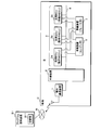
- FIG. 1 is a schematic diagram illustrating the configuration of a program update system according to a first embodiment (with a dedicated ECU).
- 3 is a block diagram illustrating the configuration of a general-purpose ECU and the like.
- FIG. It is an explanatory view which illustrates one mode of composition information on a general-purpose ECU.
- FIG. 6 is an explanatory diagram illustrating an example of updating a program of a general-purpose ECU.
- 4 is a flowchart illustrating a process of a control unit of a general-purpose ECU (standby ECU). It is a schematic diagram which illustrates the structure of the program update system which concerns on Embodiment 2 (without special ECU).
- the object of the present disclosure is to provide a program update system or the like that can shorten the period during which the vehicle-mounted ECU cannot control the vehicle-mounted device when updating the program of the vehicle-mounted ECU.
- a program update system is a program update system that performs a process for updating a program of an in-vehicle ECU mounted on a vehicle, and is included in the in-vehicle ECU and includes a plurality of types of programs. And a plurality of general-purpose ECUs that perform different functions depending on the type of the program to be executed, the general-purpose ECU being in a state of outputting information for controlling an in-vehicle device mounted on the vehicle.
- the standby ECU When a program of the general-purpose ECU is updated, the standby ECU includes an operating ECU and a standby ECU that is in a state of not outputting information for controlling the vehicle-mounted device, and the standby ECU is transmitted from an external server outside the vehicle.
- the operating ECU that acquires the update program that is stored in the storage unit of its own ECU and outputs the information for controlling the in-vehicle device.
- the operation in ECU running previous version of the program update makes a transition to waiting ECU stops the output of the information for controlling the vehicle device.
- the standby ECU when updating the program of the general-purpose ECU included in the vehicle-mounted ECU, acquires the update program transmitted from the external server outside the vehicle and stores it in the storage unit of its own ECU. Since the standby ECU does not output the information for controlling the in-vehicle device, the in-vehicle device is not affected even if the process of storing the update program is performed. Further, while the standby ECU is performing the process of storing the update program, the operating ECU outputs information for controlling the in-vehicle device, so that the operating ECU cannot control the in-vehicle device during a period. Does not occur.
- the processing such as decoding of the update program does not occur. Therefore, when updating the program of the general-purpose ECU (vehicle-mounted ECU), the period during which the vehicle-mounted ECU cannot control the vehicle-mounted device can be shortened.
- the standby ECU controls the on-vehicle device after the on-vehicle device corresponding to the update program stops.
- the in-operation ECU stops outputting the information for controlling the in-vehicle device Transition.
- the operating ECU stops outputting the information for controlling the in-vehicle device. Then, the ECU transits to the standby ECU, and the standby ECU starts outputting information for controlling the vehicle-mounted device and transits to the operating ECU. Therefore, the program of the general-purpose ECU can be surely updated.
- the standby ECU stores the program that was being executed at the time when it was the operating ECU in the storage unit, and transmitted from the external server.
- the program that was being executed when the ECU was in operation is deleted.
- the standby ECU stores and retains the old program that was being executed at the time when the ECU was in operation in the storage unit. Therefore, in the unlikely event that a problem occurs in the update program, Also, the old program can be used for recovery (rollback).
- the vehicle-mounted ECU includes the general-purpose ECU and a dedicated ECU that is directly connected to the vehicle-mounted device, and the general-purpose ECU is directly connected to the vehicle-mounted device.
- the information for controlling the vehicle-mounted device is generated and the information is transmitted to the dedicated ECU, the dedicated ECU receives the information transmitted by the general-purpose ECU, and the own ECU based on the information.
- the in-vehicle device directly connected to.
- the general-purpose ECU exhibits a plurality of different functions depending on the type of program to be executed.
- Each of the functions corresponds to the on-vehicle device to be controlled, but the on-vehicle device and the ECU that controls the driving of the on-vehicle device need to be directly connected by a wire harness such as a serial cable or an internal bus. ..
- the general-purpose ECU does not directly connect to the in-vehicle device to be driven, but generates and outputs information for controlling the in-vehicle device.
- the dedicated ECU is directly connected to the in-vehicle device to be driven, and the dedicated ECU acquires the information output by the general-purpose ECU and drives the in-vehicle device directly connected based on the information. Therefore, it is not necessary to connect each of the general-purpose ECUs and each of the in-vehicle devices with individual wire harnesses for wiring.
- the dedicated ECU that is directly connected to the in-vehicle device to be driven is often configured integrally with the in-vehicle device, and tends to have a high degree of dependence on the mechanism or structure of the in-vehicle device. Is less frequent.
- the program executed by the general-purpose ECU performs a process of generating information for controlling the in-vehicle device, and the frequency of update is exclusive for improving running safety or security measures. It will be higher than the ECU program. Therefore, by causing a general-purpose ECU to execute a program that is frequently updated, and updating the program of the general-purpose ECU by the program update system, the period during which the general-purpose ECU cannot control the in-vehicle device is effectively shortened. can do.
- the general-purpose ECU and the dedicated ECU are connected via a relay device that integrates a plurality of communication systems, and the communication to which the general-purpose ECU is connected.
- the system and the communication system to which the dedicated ECU is connected are different.
- the communication system to which the general-purpose ECU is connected and the communication system to which the dedicated ECU is connected are different from each other, so that the general-purpose ECU is connected to the communication system to which the dedicated ECU is connected.
- the influence of traffic generated in the communication system can be reduced. Therefore, when the relay device relays and transmits the update program transmitted from the external server outside the vehicle to the general-purpose ECU, the transmission of the update program suppresses an increase in traffic of the communication system to which the dedicated ECU is connected. can do.
- An update processing program is included in an in-vehicle ECU mounted on a vehicle in a computer, and is capable of executing a plurality of types of programs, and exhibits different functions depending on the type of the program to be executed.
- a plurality of general-purpose ECUs which are operating ECUs in a state of outputting information for controlling an in-vehicle device mounted on the vehicle, or standby ECUs in a state of not outputting information for controlling the in-vehicle device
- the standby ECU acquires the update program transmitted from the external server outside the vehicle and stores the update program in the storage unit of the own ECU, and the standby ECU is mounted on the vehicle.
- a computer by causing a computer to execute the update processing program, it can be made to function as a program update system.
- the computer is not limited to the one incorporated in a general-purpose ECU.
- the computer may be incorporated in a repro master that controls transmission of the update program to the general-purpose ECU, such as a relay device (gateway) communicatively connected to the general-purpose ECU.
- An update processing program causes the computer to generate information for the general-purpose ECU to control the in-vehicle device, and is included in the in-vehicle ECU and directly connected to the in-vehicle device.
- the dedicated ECU is caused to execute a process of transmitting the generated information.
- the general-purpose ECU is caused to generate information by causing the computer to execute the update processing program, and the information is transmitted to the dedicated ECU directly connected to the in-vehicle device. Therefore, it is not necessary to directly connect the general-purpose ECU and the in-vehicle device, and the policy in the vehicle can be optimized.
- the general-purpose ECU and the dedicated ECU are connected via a relay device that integrates a plurality of communication systems, and the communication to which the general-purpose ECU is connected.
- the system and the communication system to which the dedicated ECU is connected are different.
- the communication system to which the general-purpose ECU is connected and the communication system to which the dedicated ECU is connected are different from each other, so that the communication system to which the general-purpose ECU is connected when the update program is transmitted. It is possible to suppress the influence of the traffic on the communication system to which the dedicated ECU is connected.
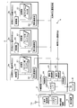
- FIG. 1 is a schematic diagram illustrating the configuration of a program update system S according to the first embodiment (with a dedicated ECU 6).
- FIG. 2 is a block diagram illustrating the configuration of the general-purpose ECU 3 and the like.
- the vehicle C is equipped with a vehicle outside communication device 1, a relay device 2, and a program updating system S including a plurality of general-purpose ECUs 3.
- the vehicle exterior communication device 1 connects to the vehicle exterior network N, and the general-purpose ECU 3 acquires a program or data from the program provision device S1 connected to the vehicle exterior network N via the vehicle exterior communication device 1 and the relay device 2.
- the relay device 2 may function as a program updating device (repromaster) that transmits the program or data acquired from the program providing device S1 to the general-purpose ECU 3.
- the program providing device S1 is a computer such as a server connected to an external network N such as the Internet or a public line network, and corresponds to an external server outside the vehicle.
- the storage unit S11 of the program providing device S1 stores (stores) a program or data created by a manufacturer of the vehicle-mounted ECU (general-purpose ECU 3 or dedicated ECU 6) for controlling the vehicle-mounted ECU.
- the program or data is transmitted to the vehicle C as an update program, and is used to update the program or data of the vehicle-mounted ECU mounted on the vehicle C.
- the program providing device S1 (external server) configured as described above is also referred to as an OTA (Over The Air) server.
- the vehicle-mounted ECU installed in the vehicle acquires the update program transmitted by wireless communication from the program providing device S1 and applies the update program as a program for executing the update program, thereby updating the program executed by the own ECU (repro). can do.
- the program will be described as including a program code including a control syntax for the in-vehicle ECU to perform processing, and an external file in which data to be referred to when executing the program code is described.
- the external file in which the program code and the data are written is transmitted from the program providing device S1 as, for example, an encrypted archive file.
- the vehicle C is provided with a plurality of dedicated ECUs 6 and an in-vehicle device 7 directly connected to the dedicated ECUs 6 by a wire harness such as a serial cable. That is, the vehicle C is provided with the general-purpose ECU 3 and the dedicated ECU 6 as vehicle-mounted ECUs.
- the relay device 2 is a gateway including a plurality of segments of a general-purpose ECU communication system to which a plurality of general-purpose ECUs 3 are connected and a dedicated ECU communication system to which a plurality of dedicated ECUs 6 are connected.
- the general-purpose ECUs 3 are connected to each other via a general-purpose ECU communication system so that they can communicate with each other.
- the dedicated ECUs 6 are connected to each other via a dedicated ECU communication system so that they can communicate with each other.
- the general-purpose ECU 3 and the dedicated ECU 6 are connected to each other via the relay device 2 so that they can communicate with each other.
- the in-vehicle LAN 4 is configured by the general-purpose ECU communication system and the dedicated ECU communication system included in the relay device 2.
- each of the general-purpose ECUs 3 is capable of executing a plurality of different types of programs and exhibits different functions depending on the type of the program to be executed. That is, the general-purpose ECUs 3 have the same hardware specifications, for example, and by applying the engine program to one general-purpose ECU 3, information (data) for controlling the engine is output and other general-purpose ECUs 3 are output. By applying the brake program to the ECU 3, data for controlling the brake is output. The output data is received by the dedicated ECU 6 for engine or brake corresponding to the data via the relay device 2.
- Each of these dedicated ECUs 6 drives and controls the vehicle-mounted device 7 directly connected to its own ECU based on the data received from the corresponding general-purpose ECU 3.
- the engine dedicated ECU 6 connected to the engine vehicle-mounted device 7 receives data output from the general-purpose ECU 3 to which the engine program is applied, and drives the engine vehicle-mounted device 7 that is an actuator. Drive control such as start or stop is performed.
- the general-purpose ECU 3 includes an operating ECU 3a and a standby ECU 3b.
- the operating ECU 3a is the general-purpose ECU 3 that is in a state of generating and outputting data to be transmitted to the dedicated ECU 6 as described above.
- the standby ECU 3b is the general-purpose ECU 3 in the standby state without outputting the data. That is, the operating ECU 3a and the waiting ECU 3b are determined by the state of the general-purpose ECU 3. Details will be described later in the description of the flowchart and the like.
- the communication device 1 outside the vehicle and the relay device 2 are communicatively connected by a wire harness such as a serial cable.
- the relay device 2 and the vehicle-mounted ECU are communicatively connected by an in-vehicle LAN 4 compatible with a communication protocol such as CAN (Control Area Network / registered trademark) or Ethernet (registered trademark).
- the vehicle exterior communication device 1 includes a vehicle exterior communication unit 11 and an input / output I / F (interface) 12 for communicating with the relay device 2.
- the external communication unit 11 is a communication device for performing wireless communication using a mobile communication protocol such as 3G, LTE, 4G, or WiFi, and is a program providing device via an antenna 13 connected to the external communication unit 11. Data is transmitted / received to / from S1. Communication between the vehicle exterior communication device 1 and the program providing device S1 is performed via an external network N such as a public line network or the Internet.
- the input / output I / F 12 is a communication interface for serial communication with the relay device 2, for example.
- the vehicle exterior communication device 1 and the relay device 2 communicate with each other via an input / output I / F 12 and a wire harness such as a serial cable connected to the input / output I / F 12.
- the vehicle exterior communication device 1 is a device separate from the relay device 2, and these devices are communicably connected by the input / output I / F 12 or the like, but the invention is not limited to this.
- the vehicle exterior communication device 1 may be built in the relay device 2 as a component of the relay device 2.
- the relay device 2 includes a control unit 20, a storage unit 21, and an in-vehicle communication unit 23.
- the relay device 2 acquires the update program received from the program providing device S1 by the outside communication device 1 by wireless communication from the outside communication device 1 and transmits (relays) the update program to the general-purpose ECU 3 via the in-vehicle LAN 4.
- the relay device 2 may be configured as one functional unit of the body ECU that controls the entire vehicle C.
- the control unit 20 is configured by a CPU (Central Processing Unit), an MPU (Micro Processing Unit), or the like, and reads and executes a control program and data stored in advance in the storage unit 21 to perform various control processes and Arithmetic processing and the like are performed.
- the control unit 20 corresponds to an acquisition unit that acquires the update program transmitted from the program providing device S1 via the vehicle exterior communication device 1.
- the storage unit 21 is configured by a volatile memory device such as a RAM (Random Access Memory) or a non-volatile memory device such as a ROM (Read Only Memory), an EEPROM (Electrically Erasable Programmable ROM) or a flash memory, A control program and data to be referred to during processing are stored in advance. Alternatively, the control program may be downloaded from an external computer (not shown) connected to a communication network (not shown) and stored in the storage unit 21. Further, the storage unit 21 stores the configuration information of all the vehicle-mounted ECUs (general-purpose ECU 3 and dedicated ECU 6) mounted on the vehicle C, the update program acquired from the program providing apparatus S1, and the update program when the update program is transmitted to the vehicle-mounted ECU. Information about the progress status is stored.
- a volatile memory device such as a RAM (Random Access Memory) or a non-volatile memory device such as a ROM (Read Only Memory), an EEPROM (Electrically Erasable Programmable ROM) or
- the in-vehicle communication unit 23 is an input / output interface using a communication protocol such as CAN (Control Area Network) or Ethernet (registered trademark), and the control unit 20 is connected to the in-vehicle LAN 4 via the in-vehicle communication unit 23.
- the vehicle-mounted ECU generally-purpose ECU 3, dedicated ECU 6) or another vehicle-mounted device such as the relay device 2 communicates with each other.
- a plurality of (two in the drawing) in-vehicle communication units 23 are provided, and each in-vehicle communication unit 23 is connected to a communication line that constitutes the in-vehicle LAN 4.
- the in-vehicle LAN 4 is divided into a plurality of segments. As shown in FIG. 1, by connecting a plurality of general-purpose ECUs 3 to one segment, the one segment functions as a general-purpose ECU communication system. By connecting a plurality of dedicated ECUs 6 to the other segment, the other segment functions as a dedicated ECU communication system.
- the general-purpose ECU 3 includes a control unit 30, a storage unit 31, and an in-vehicle communication unit 32.
- the control unit 30 is configured by a CPU or MPU.
- the in-vehicle communication unit 32 is an input / output interface using a communication protocol similar to that of the in-vehicle communication unit 23 of the relay device 2.
- the control unit 30 receives the update program transmitted (relayed) from the relay device 2 via the in-vehicle communication unit 32 and acquires the update program.
- the storage unit 31 is configured by a volatile memory device such as a RAM (Random Access Memory) or a non-volatile memory device such as a ROM (Read Only Memory), an EEPROM (Electrically Erasable Programmable ROM), or a flash memory,
- a volatile memory device such as a RAM (Random Access Memory) or a non-volatile memory device such as a ROM (Read Only Memory), an EEPROM (Electrically Erasable Programmable ROM), or a flash memory
- ROM Read Only Memory
- EEPROM Electrically Erasable Programmable ROM
- flash memory a volatile memory device
- the program or data of the general-purpose ECU 3 is stored. This program or data is a target to be updated by the update program transmitted from the relay device 2.
- General-purpose ECU 3 is configured to be able to execute a plurality of different types of programs.
- the engine program is stored in the storage unit 31 of the general-purpose ECU 3, and the control unit 30 of the general-purpose ECU 3 reads and executes the engine program, so that the general-purpose ECU 3 causes the engine (the in-vehicle device 7 for the engine) to execute. Generates information for controlling, and transmits (outputs) the information.
- the control unit 30 of the general-purpose ECU 3 reads and executes the brake program, so that the general-purpose ECU 3 causes the brake (the vehicle-mounted device for the brake). Information for controlling 7) is generated, and the information is transmitted (output).
- the general-purpose ECU 3 is configured to exert different functions depending on the type of the program stored in the storage unit 31.
- the general-purpose ECU 3 includes the operating ECU 3a and the standby ECU 3b.
- the currently executing program is stored in the storage unit 31 of the operating ECU 3a.
- the storage unit 31 of the waiting ECU 3b stores the previous version of the program that was previously executed (old program). If the program of the general-purpose ECU 3 has never been updated by the update program, the storage unit 31 of the waiting ECU 3b is in an empty state in which no program is stored.
- the storage unit 31 of each of the general-purpose ECUs 3 stores information regarding the operating state of the own ECU.
- the information on the operating state is, for example, flag data indicating the operating state or the standby state.
- the configuration information of all of the general-purpose ECUs 3 is stored in each of the storage units 31 of each of the general-purpose ECUs 3, that is, the configuration information of all of the general-purpose ECUs 3 is shared by each of the general-purpose ECUs 3.
- each of the general-purpose ECUs 3 can recognize the operating state of not only the own ECU but also all the general-purpose ECUs 3, and which general-purpose ECU 3 is operating (in operation). It is the ECU 3a), and it is possible to recognize which general-purpose ECU 3 is on standby (standby ECU 3b).
- the dedicated ECU 6 includes a control unit, a storage unit, and an in-vehicle communication unit, which are not shown. Further, the dedicated ECU 6 includes an input / output I / F (not shown) similar to the relay device 2, and can communicate with the vehicle-mounted device 7 by a wire harness such as a serial cable connected to the input / output I / F. Directly connected. As described above, the dedicated ECU 6 outputs the data output from the general-purpose ECU 3 to which the program (engine program) corresponding to the in-vehicle device 7 (for example, the in-vehicle device 7 for an engine) directly connected to the own ECU is applied (in-vehicle device). (Information for controlling 7) is received, and drive control such as driving or stopping of the vehicle-mounted device 7 directly connected to the own ECU is performed based on the data.
- the program engine program
- the in-vehicle device 7 for example, the in-vehicle device 7 for an engine
- the display device 5 is communicably connected to the input / output I / F 24 of the relay device 2 by a wire harness such as a serial cable.
- the display device 5 is an HMI (Human Machine Interface) device such as a car navigation display.
- HMI Human Machine Interface
- the relay device 2 may transmit information about the state of each of the general-purpose ECUs 3 (whether it is the operating ECU 3a or the waiting ECU 3b) to the display device 5 and display the state on the display device 5.
- the connection form of the display device 5 and the relay device 2 is not limited to the connection form of the input / output I / F 24 and the like, and the display device 5 and the relay device 2 may be a connection form via the in-vehicle LAN 4.
- An IG switch 8 (ignition switch) for starting or stopping the vehicle is communicatively connected to the input / output I / F 24 of the relay device 2 by a wire harness such as a serial cable.
- the control unit 20 of the relay device 2 acquires (receives) the signal output (transmitted) from the IG switch 8 via the input / output I / F 24.
- the control unit 20 of the relay device 2 transmits to the general-purpose ECU 3 and the dedicated ECU 6 which are vehicle-mounted ECUs via the in-vehicle communication unit 23, as information regarding ON or OFF of the IG switch 8. Therefore, the general-purpose ECU 3 can acquire the information regarding the ON or OFF of the IG switch 8 based on the information transmitted from the relay device 2.
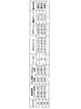
- FIG. 3 is an explanatory diagram illustrating an example of the configuration information of the general-purpose ECU 3.
- the storage information of each general-purpose ECU 3 stores the configuration information of all general-purpose ECUs 3.
- the configuration information is based on, for example, an information group (vehicle configuration information master table) indicated by the items in the table shown in FIG.
- the configuration information includes, for example, the serial number (serial number) of the general-purpose ECU 3, the ECU part number (part number, model number), the software part number, the program version, and the MAC (Media Access). Control) address, IP address, functional group, and operation state, and is managed in association with the ECU-ID by a serial number or the like set so as not to overlap in each general-purpose ECU 3.
- the manufacturing number is a number given when the general-purpose ECU 3 is manufactured, and is composed of a lot number indicating a production base and a serial number at the time of manufacturing, and is a unique number that can uniquely identify the ECU. It is a number.
- the ECU part number (part number, model number) is a number that identifies the type of the vehicle-mounted ECU, and is, for example, a part number.
- the Software part number is a number for identifying the type of software of the program.
- the version is the version of the program stored in the storage unit.
- the MAC address is an address corresponding to the data ring layer when the in-vehicle communication unit 23 of the general-purpose ECU 3 is a communication port compatible with Ethernet.
- the MAC address is a number given at the time of manufacturing the in-vehicle communication unit 23, is composed of a vendor code indicating the manufacturer and a serial number at the time of manufacturing, and is a unique number that can uniquely identify the ECU. is there.
- the IP address is an address corresponding to the network layer when performing communication using TCP / IP when the in-vehicle communication unit 23 is a communication port compatible with Ethernet.
- the function group is a division of the functions of the program specified by the Software part number, and indicates, for example, the function classification or type of the in-vehicle device 7 to be controlled.
- the operating state is information regarding the state of the general-purpose ECU 3 and indicates whether the operating state or the standby state.
- the configuration information of the general-purpose ECU 3 includes identification information for identifying the general-purpose ECU 3. Since the IP address is an address that can be arbitrarily determined according to the setting of the in-vehicle communication unit 23, it is desirable to use a serial number or a MAC address as the identification information for identifying the general-purpose ECU 3.
- ECU-IDs 001 and 003 there are two general-purpose ECUs 3 (ECU-IDs 001 and 003) whose functional groups are engines.
- the general-purpose ECU 3 whose ECU-ID is 001 is in operation, and is executing the engine program as the in-operation ECU 3a.
- the general-purpose ECU 3 whose ECU-ID is 003 is in a standby state, and stores the old program (previous version program) for the engine that was previously executed as a standby ECU 3b in the storage unit of its own ECU.
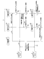
- FIG. 4 is an explanatory diagram illustrating one mode of updating the program of the general-purpose ECU 3.
- a program update by the program update system S including a plurality of general-purpose ECUs 3 (operating ECU 3a, waiting ECU 3b) will be described using a sequence diagram including processing of the relay device 2, the operating ECU 3a, and the waiting ECU 3b. To do.
- the relay device 2 transmits the update program acquired from the program providing device S1 to the waiting ECU 3b (S1). For example, the relay device 2 transmits the update program by multicast to all the general-purpose ECUs 3.
- Each of the general-purpose ECUs 3 stores in the storage unit 31 whether the operating state of its own ECU is in operation (operating ECU 3a) or in standby (standby ECU 3b). Therefore, the waiting ECU 3b acquires (receives) the update program transmitted from the relay device 2.
- the relay device 2 stores the configuration information of all the general-purpose ECUs 3 in the storage unit 21, identifies the general-purpose ECU 3 in standby, that is, the standby ECU 3b, and unicasts the update program to the standby ECU 3b. You may send it at.
- the standby ECU 3b normally ends the acquisition (reception) of the update program, it may transmit (reply) to the relay device 2 that the reception of the update program has been successful.
- the standby ECU 3b stores the acquired (received) update program in the storage unit 31 of its own ECU (S2).
- the standby ECU 3b acquires or stores the update program.
- the old program is deleted.
- IG switch 8 is turned off (S3).
- the vehicle C is stopped by turning off the IG switch 8.
- the vehicle-mounted device 7 connected to the dedicated ECU 6 also stops.
- the relay device 2 transmits information regarding that the IG switch 8 is turned off to all the general-purpose ECUs 3 (the operating ECU 3a and the waiting ECU 3b).
- the operating ECU 3a that has received the information stops the generation and transmission of the information for controlling the vehicle-mounted device 7.
- the waiting ECU 3b sends a signal to the operating ECU 3a to shift to the waiting state (S4).
- the standby ECU 3b refers to the header information of the update program stored in the process of (S2), and specifies the Software part number, version, and function group of the update program.
- the general-purpose ECU 3 identifies the operating ECU 3a (the operating general-purpose ECU 3) that has the same functional group or Software part number as the identified functional group or Software part number, for example.
- the function group of the update program is the engine
- the function group specifies the ECU 3a during operation of the engine.
- the operating ECU 3a is specified by, for example, the serial number or the MAC address.
- the waiting ECU 3b transmits a signal for transitioning to the waiting state to the specified operating ECU 3a.
- the operating ECU 3a which has received the signal for transitioning to the standby state, transitions its own ECU to the standby ECU 3b (S5).
- the operating ECU 3a that has received the signal for transitioning to the standby state changes the operating state of its own ECU from operating to standby in the configuration information stored in the storage unit 31 of its own ECU.
- the general-purpose ECU 3 that was the operating ECU 3a transits to the standby ECU 3b.
- the standby ECU 3b After changing the configuration information stored in the storage unit 31 of its own ECU and transiting to the standby ECU 3b, the standby ECU 3b transmits the changed configuration information to all the general-purpose ECUs 3 and the relay device 2 by, for example, multicasting. May be.
- the standby ECU 3b which has transmitted the signal to transition to the standby state, transitions its own ECU to the operating ECU 3a (S6).
- the standby ECU 3b that has transmitted the signal for transitioning to the standby state changes the operating state of its own ECU from standby to active in the configuration information stored in the storage unit 31 of its own ECU.
- the general-purpose ECU 3 that was the standby ECU 3b transitions to the operating ECU 3a.
- the operating ECU 3a After changing the configuration information stored in the storage unit 31 of the own ECU and transiting to the operating ECU 3a, transmits the changed configuration information to all the general-purpose ECUs 3 and the relay device 2 by, for example, multicasting. You may.
- the transmitted configuration information includes information about the operating state of the ECU itself, and the software part number, version, and function group changed based on the acquired update program.
- the general-purpose ECU 3 that has changed the operation state every time the program is updated receives all the configuration information including the operation state of the own ECU and the Software part number, the version, and the function group corrected based on the acquired update program. It is transmitted to the general-purpose ECU 3 and the relay device 2. Therefore, each general-purpose ECU 3 and the relay device 2 can always share the latest configuration information of each general-purpose ECU 3.
- IG switch 8 is turned on (S7).
- the vehicle C is started by turning on the IG switch 8.
- Information about the fact that the IG switch 8 is turned on is transmitted from the relay device 2 to all the general-purpose ECUs 3.
- the standby ECU 3b performs a standby process of waiting for the update program transmitted from the relay device 2 (S8).
- the storage unit 31 of the standby ECU 3b stores (saves) an old program that is the same type as the update program transmitted from the relay device 2 last time and is a previous version of the update program.
- the waiting ECU 3b does not execute the old program but performs a waiting process. Therefore, the standby ECU 3b substantially stops outputting the information for controlling the vehicle-mounted device 7. Substantially stopping the output of information for controlling the vehicle-mounted device 7 is not limited to the case where the standby ECU 3b stops outputting all information.
- the waiting ECU 3b may output (transmit) information (signal) that does not affect the control of the vehicle-mounted device 7.
- the operating ECU 3a executes the update program stored in the storage unit 31 and outputs information for controlling the vehicle-mounted device 7 (S9).
- the operating ECU 3a executes the update program stored in the process of (S2), generates information for controlling the in-vehicle device 7 corresponding to the update program, and is directly connected to the in-vehicle device 7. The information is output (transmitted) to the ECU 6.
- the standby ECU 3b acquires the next update program (S10), as in the process of (S1).
- the standby ECU 3b as a preparatory process for acquiring and storing the next update program from the relay device 2, for example, when information regarding the existence of a new update program is transmitted from the program providing device S1 via the relay device 2, the own ECU 3b The old program stored in the storage unit 31 is deleted.
- the standby ECU 3b In order to apply the update program acquired by the standby ECU 3b, the standby ECU 3b is in operation while the vehicle-mounted device corresponding to the update program is stopped, for example, from when the IG switch 8 is turned off. This can be dealt with by performing a process of transitioning to the ECU 3a.
- the transition from the standby ECU 3b to the operating ECU 3a is performed by, for example, a process of changing the information indicating the operating state of the own ECU from the standby state to the operating state in the configuration information stored in the storage unit 31 of the own ECU. Therefore, the transition can be performed in a short time. Therefore, the application of the update program, that is, the update process (repro process) of the program can be completed in a short time, and the time during which the general-purpose ECU 3 cannot control the vehicle-mounted device 7 can be reduced.
- the in-operation ECU 3a that has received the signal for transitioning to the standby state transits to the standby ECU 3b while the in-vehicle device corresponding to the update program is stopped, for example, from the off state to the on state of the IG switch 8.
- the activated standby ECU 3b has stopped generating and outputting information for controlling the in-vehicle device 7. Therefore, it is possible to prevent the old program stored (saved) in the storage unit 31 of the ECU 3b during standby from being executed.
- the operating ECU 3a executing the update program makes a transition to the standby ECU 3b to stop the execution of the update program, and the standby ECU 3b makes a transition to the operating ECU 3a.
- a rollback process for executing the old program of the own ECU may be performed. By performing the rollback process, the control of the vehicle-mounted device 7 corresponding to the update program can be continued.
- the configuration information of all the general-purpose ECUs 3 is stored in the storage unit 31 of each of the general-purpose ECUs 3, but the configuration information is not limited to this. Only the configuration information of its own ECU is stored in the storage unit 31 of each of the general-purpose ECUs 3, and the relay device 2 communicates with each of the general-purpose ECUs 3 and acquires (receives) each of the configuration information transmitted from each of the general-purpose ECUs 3.
- the configuration information may be aggregated. That is, the storage unit 21 of the relay device 2 stores the configuration information of all the general-purpose ECUs 3, and each of the general-purpose ECUs 3 acquires the configuration information of all the general-purpose ECUs 3 by communicating with the relay device 2. May be
- the standby ECU 3b specifies the operating ECU 3a that is executing a program of the same type as the acquired update program, and sends a signal to the operating ECU 3a to transition to the standby state, but the present invention is not limited to this.
- the relay device 2 may identify the operating ECU 3a that is executing a program of the same type as the acquired update program, and may send a signal to the operating ECU 3a to transition to the standby state.
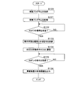
- FIG. 5 is a flowchart illustrating the processing of the control unit of the general-purpose ECU 3 (standby ECU 3b).
- the control unit 30 of the general-purpose ECU 3 (the control unit 30 of the standby ECU 3b) in the standby ECU 3b waits for the update program relayed by the relay device 2 when the vehicle C is in the activated state (the IG switch 8 is on). The following processing is performed.
- the control unit 30 of the waiting ECU 3b acquires the update program (S100).
- the control unit 30 may delete the old program as a preparation process for acquiring the program. By deleting the old program, it is possible to prevent the storage area of the storage unit 31 of the own ECU from becoming tight.
- the control unit 30 of the waiting ECU 3b stores the update program (S101).
- the control unit 30 stores the acquired update program in the storage unit 31 of its own ECU.
- the control unit 30 of the waiting ECU 3b determines whether or not an IG off signal has been received (S102).
- the standby ECU 3b determines whether or not the IG off signal is received based on, for example, the information about the turning off of the IG switch 8 (IG off signal) transmitted from the relay device 2.
- the control unit 30 of the waiting ECU 3b performs a loop process to execute the process of S102 again.
- the control unit 30 of the waiting ECU 3b transmits a signal for changing the operating state (S103).
- the control unit 30 causes the operating ECU 3a, which is executing a program of the same type as the acquired update program, that is, the program of the previous version of the update program, to change the operating state (transition from the operating ECU 3a to the standby ECU 3b). Signal).
- the operating ECU 3a that has received the signal stores the information regarding the signal in the storage unit 31 of the own ECU so as to transition the own ECU to the waiting ECU 3b.
- the operating ECU 3a that receives the signal may change the operating state of the own ECU from the operating state to the standby state in the update information stored in the storage unit 31 of the own ECU.
- the control unit 30 of the waiting ECU 3b changes its own ECU to the operating ECU 3a. (S104).
- the control unit 30 of the waiting ECU 3b changes to the operating ECU 3a by changing the operating state of the own ECU from the standby state to the operating state in the update information stored in the storage unit 31 of the own ECU.
- the vehicle-mounted device 7 corresponding to the update program and the dedicated ECU 6 directly connected to the vehicle-mounted device 7 are stopped and then started. While the in-vehicle device 7 corresponding to the update program is stopped, the standby ECU 3b that has acquired the update program is transited to the operating ECU 3a to stop the in-vehicle device 7 only for applying the update program. This can be avoided, and the period during which the general-purpose ECU 3 cannot control the vehicle-mounted device 7 can be shortened.
- the old program the program of the previous version of the update program
- the waiting ECU 3b performs the waiting process without executing the old program. Therefore, it is possible to prevent the control of the vehicle-mounted device 7 from being affected. That is, the standby ECU 3b substantially stops outputting the information (signal) for controlling the in-vehicle device 7.
- the control unit 30 modifies the information about the operating state of the self ECU in the configuration information stored in the storage unit 31 of the self ECU when the self ECU changes to the operating ECU 3a.
- the correction content of the information relating to the operating state is such that the operating state of the self ECU is changed from the standby state to the operating state, and the operating state of the operating ECU 3a that has transmitted the signal in the process of (S103) is changed from the operating state to the standby state.
- the correction content of the configuration information also includes changing the Software part number, version and function group of the self ECU to the Software part number, version and function group of the acquired update program.
- the control unit 30 sends the modified configuration information to the other general-purpose ECU 3 and the relay device 2.
- the other general-purpose ECU 3 that has received the configuration information replaces the configuration information stored in its own ECU with the received configuration information, so that the general-purpose ECU 3 includes the operation state (in operation or standby) at the present time. You can share the configuration information.
- the control unit 30 of the general-purpose ECU 3 that has become the operating ECU 3a determines whether or not an IG ON signal has been received (S105).
- the control unit 30 of the general-purpose ECU 3 that has become the operating ECU 3a determines whether or not the IG-off signal is received based on, for example, the information about the ON of the IG switch 8 (IG-on signal) transmitted from the relay device 2. To do.
- control unit 30 of the general-purpose ECU 3 that has become the operating ECU 3a performs a loop process to execute the process of S105 again.
- the control unit 30 of the general-purpose ECU 3 that has become the operating ECU 3a outputs the control information of the in-vehicle device 7 (S106).
- the control unit 30 executes the acquired update program to generate information for controlling the in-vehicle device 7 corresponding to the update program, and transmits the information to the dedicated ECU 6 directly connected to the in-vehicle device 7. (Output.
- the previous version of the update program (old program) is stored in the storage unit 31 of the general-purpose ECU 3 that has become the standby ECU 3b upon receiving a signal that changes the operating state.
- the general-purpose ECU 3 that has become the standby ECU 3b performs a standby process of waiting for the next update program transmitted from the relay device 2 without executing the old program.
- the general-purpose ECU 3 that has become the standby ECU 3b executes the processing from S100.
- the waiting ECU 3b acquires the update program and makes a transition to the operating ECU 3a, thereby updating the update program. Run the program.
- the operating ECU 3a that was executing the program (old program) of the previous version of the update program transits to the waiting ECU 3b.
- the standby ECU 3b changes each time the program is updated by the update program. Since the standby ECU 3b has stopped the generation and output of information for controlling the vehicle-mounted device 7, it is possible to obtain the update program even while the vehicle-mounted device 7 is operating.
- the transition from the waiting ECU 3b to the operating ECU 3a is performed in an extremely short time while the IG switch 8 is turned off, the time during which the in-vehicle device 7 cannot be controlled by the operating ECU 3a is shortened. You can Further, since the standby ECU 3b holds the program (old program) of the previous version of the update program, when a problem occurs in the update program, the rollback process can be performed by the old program.
- FIG. 6 is a schematic diagram illustrating the configuration of the program update system S according to the second embodiment (without the dedicated ECU 6).
- the program update system S of the second embodiment is different from the first embodiment in that the general-purpose ECU 3 and the vehicle-mounted device 7 are connected to each other in all combinations of the general-purpose ECU 3 and the vehicle-mounted device 7.
- the general-purpose ECU 3 includes the operating ECU 3a and the standby ECU 3b as in the first embodiment. All the general-purpose ECUs 3 are communicably connected to all the vehicle-mounted devices 7 to be controlled by a wire harness such as a serial cable. Each of the general-purpose ECUs 3 includes an input / output I / F (not shown) similar to the relay device 2 or the dedicated ECU 6 of the first embodiment, and the wire harness is connected to the input / output I / F.
- FIG. 6 three general-purpose ECUs 3 and two vehicle-mounted devices 7 are shown as an example.
- Each of the general-purpose ECUs 3 is connected to each of the two vehicle-mounted devices 7 by two wire harnesses. That is, the general-purpose ECU 3 and the vehicle-mounted ECU are connected by a wire harness so as to correspond to all combinations of the general-purpose ECU 3 and the vehicle-mounted device 7.
- the general-purpose ECU 3 whose operating state is operating that is, the operating ECU 3a executes a program stored in the storage unit 31, generates information for controlling the vehicle-mounted device 7 corresponding to the program, and outputs the generated information. Output to the vehicle-mounted device 7 via the input / output I / F.
- C vehicle S program update system S1 program providing device (external server) S11 storage unit 1 vehicle exterior communication device 11 vehicle exterior communication unit 12 input / output I / F 13 antenna 2 relay device 20 control unit 21 storage unit 22 recording medium 23 in-vehicle communication unit 24 input / output I / F 3 General-purpose ECU (vehicle-mounted ECU) 3a Operating ECU 3b Standby ECU 30 control unit 31 storage unit 32 in-vehicle communication unit 4 in-vehicle LAN 5 Display device 6 Dedicated ECU (vehicle-mounted ECU) 7 In-vehicle device 8 IG switch
Landscapes
- Engineering & Computer Science (AREA)
- Theoretical Computer Science (AREA)
- General Engineering & Computer Science (AREA)
- Software Systems (AREA)
- General Physics & Mathematics (AREA)
- Mechanical Engineering (AREA)
- Physics & Mathematics (AREA)
- Computer Security & Cryptography (AREA)
- Transportation (AREA)
- Human Computer Interaction (AREA)
- Automation & Control Theory (AREA)
- Stored Programmes (AREA)
- Information Transfer Between Computers (AREA)
Priority Applications (2)
| Application Number | Priority Date | Filing Date | Title |
|---|---|---|---|
| US17/291,671 US20220004374A1 (en) | 2018-11-06 | 2019-10-17 | Program update system and update processing program |
| CN201980068959.XA CN113365879A (zh) | 2018-11-06 | 2019-10-17 | 程序更新系统及更新处理程序 |
Applications Claiming Priority (2)
| Application Number | Priority Date | Filing Date | Title |
|---|---|---|---|
| JP2018209122A JP7192415B2 (ja) | 2018-11-06 | 2018-11-06 | プログラム更新システム及び更新処理プログラム |
| JP2018-209122 | 2018-11-06 |
Publications (1)
| Publication Number | Publication Date |
|---|---|
| WO2020095645A1 true WO2020095645A1 (ja) | 2020-05-14 |
Family
ID=70612399
Family Applications (1)
| Application Number | Title | Priority Date | Filing Date |
|---|---|---|---|
| PCT/JP2019/040791 Ceased WO2020095645A1 (ja) | 2018-11-06 | 2019-10-17 | プログラム更新システム及び更新処理プログラム |
Country Status (4)
| Country | Link |
|---|---|
| US (1) | US20220004374A1 (enExample) |
| JP (1) | JP7192415B2 (enExample) |
| CN (1) | CN113365879A (enExample) |
| WO (1) | WO2020095645A1 (enExample) |
Cited By (1)
| Publication number | Priority date | Publication date | Assignee | Title |
|---|---|---|---|---|
| WO2022172498A1 (ja) * | 2021-02-15 | 2022-08-18 | 日立Astemo株式会社 | 車載型コンピュータシステムおよび自動運転支援システム |
Families Citing this family (8)
| Publication number | Priority date | Publication date | Assignee | Title |
|---|---|---|---|---|
| WO2021024589A1 (ja) * | 2019-08-06 | 2021-02-11 | 日本電気株式会社 | モビリティ制御システム、方法、および、プログラム |
| JP7283359B2 (ja) * | 2019-11-19 | 2023-05-30 | 株式会社オートネットワーク技術研究所 | 車載更新装置、及び更新処理プログラム |
| JP7419992B2 (ja) * | 2020-07-02 | 2024-01-23 | トヨタ自動車株式会社 | ソフトウェア更新装置、方法、プログラムおよび車両 |
| JP7138156B2 (ja) * | 2020-12-24 | 2022-09-15 | 本田技研工業株式会社 | 情報処理装置、輸送機器、情報処理方法及びプログラム |
| KR20230025109A (ko) * | 2021-08-13 | 2023-02-21 | 현대자동차주식회사 | 차량용 ota 업데이트 수행 장치 및 방법 |
| CN113867317B (zh) * | 2021-09-28 | 2023-07-25 | 重庆长安汽车股份有限公司 | 一种汽车控制器软件刷写方法及系统 |
| JP2023071280A (ja) * | 2021-11-11 | 2023-05-23 | トヨタ自動車株式会社 | 車両および車両の制御方法 |
| US12254308B2 (en) * | 2022-11-17 | 2025-03-18 | Mercedes-Benz Group AG | System, device and/or method for updating vehicle subsystem configurations |
Citations (5)
| Publication number | Priority date | Publication date | Assignee | Title |
|---|---|---|---|---|
| JP2004210183A (ja) * | 2003-01-07 | 2004-07-29 | Komatsu Ltd | 車載プログラムの書き換え制御装置 |
| JP2004291943A (ja) * | 2003-03-28 | 2004-10-21 | Denso Corp | 車両用制御装置 |
| JP2010028355A (ja) * | 2008-07-17 | 2010-02-04 | Mitsubishi Fuso Truck & Bus Corp | 車載ネットワークの通信管理装置 |
| WO2017149825A1 (ja) * | 2016-03-02 | 2017-09-08 | 住友電気工業株式会社 | プログラム更新システム、プログラム更新方法及びコンピュータプログラム |
| JP2017224047A (ja) * | 2016-06-13 | 2017-12-21 | クラリオン株式会社 | ソフトウェア更新装置およびソフトウェア更新システム |
Family Cites Families (16)
| Publication number | Priority date | Publication date | Assignee | Title |
|---|---|---|---|---|
| JP2003049704A (ja) * | 2001-08-02 | 2003-02-21 | Mitsubishi Motors Corp | 車両仕様識別装置 |
| JP3864747B2 (ja) * | 2001-10-09 | 2007-01-10 | 株式会社デンソー | 冗長系信号処理装置 |
| JP3776438B2 (ja) * | 2004-12-03 | 2006-05-17 | 株式会社日立製作所 | 記憶装置 |
| JP2010254069A (ja) * | 2009-04-23 | 2010-11-11 | Toyota Motor Corp | 車両用電源制御装置、車両用電源制御方法 |
| JP5998689B2 (ja) * | 2012-07-10 | 2016-09-28 | スズキ株式会社 | 車載制御システム |
| JP6056424B2 (ja) * | 2012-11-29 | 2017-01-11 | 株式会社デンソー | 車載プログラム更新装置 |
| US9600263B2 (en) * | 2014-07-21 | 2017-03-21 | Big Switch Networks, Inc. | Systems and methods for performing uninterrupted network upgrades with controllers |
| US9836300B2 (en) * | 2015-06-16 | 2017-12-05 | Lear Corporation | Method for updating vehicle ECUs using differential update packages |
| KR101792046B1 (ko) * | 2015-10-29 | 2017-11-20 | 현대자동차주식회사 | 단말기, 차량 및 그 제어 방법 |
| DE112017005462T5 (de) * | 2016-10-27 | 2019-07-18 | Sumitomo Electric Industries, Ltd. | Steuervorrichtung, Programmaktualisierungsverfahren und Computerprogramm |
| JP6690500B2 (ja) * | 2016-10-31 | 2020-04-28 | 株式会社オートネットワーク技術研究所 | 車載更新システム及び車載更新装置 |
| US10782955B2 (en) * | 2017-01-03 | 2020-09-22 | Ford Global Technologies, Llc | Pre-shutdown swap verification |
| CN110214312A (zh) * | 2017-01-24 | 2019-09-06 | 三菱电机株式会社 | 共享备用单元和控制系统 |
| CN106740587A (zh) * | 2017-02-16 | 2017-05-31 | 成都雅骏新能源汽车科技股份有限公司 | 一种纯电动汽车整车控制器可待机控制方法和装置 |
| US10564954B2 (en) * | 2017-10-11 | 2020-02-18 | Ford Global Technologies, Llc | Hybrid electric vehicle with automated software update system |
| JP6915500B2 (ja) * | 2017-11-06 | 2021-08-04 | トヨタ自動車株式会社 | 更新システム、電子制御装置、更新管理装置、及び更新管理方法 |
-
2018
- 2018-11-06 JP JP2018209122A patent/JP7192415B2/ja active Active
-
2019
- 2019-10-17 WO PCT/JP2019/040791 patent/WO2020095645A1/ja not_active Ceased
- 2019-10-17 CN CN201980068959.XA patent/CN113365879A/zh active Pending
- 2019-10-17 US US17/291,671 patent/US20220004374A1/en not_active Abandoned
Patent Citations (5)
| Publication number | Priority date | Publication date | Assignee | Title |
|---|---|---|---|---|
| JP2004210183A (ja) * | 2003-01-07 | 2004-07-29 | Komatsu Ltd | 車載プログラムの書き換え制御装置 |
| JP2004291943A (ja) * | 2003-03-28 | 2004-10-21 | Denso Corp | 車両用制御装置 |
| JP2010028355A (ja) * | 2008-07-17 | 2010-02-04 | Mitsubishi Fuso Truck & Bus Corp | 車載ネットワークの通信管理装置 |
| WO2017149825A1 (ja) * | 2016-03-02 | 2017-09-08 | 住友電気工業株式会社 | プログラム更新システム、プログラム更新方法及びコンピュータプログラム |
| JP2017224047A (ja) * | 2016-06-13 | 2017-12-21 | クラリオン株式会社 | ソフトウェア更新装置およびソフトウェア更新システム |
Cited By (3)
| Publication number | Priority date | Publication date | Assignee | Title |
|---|---|---|---|---|
| WO2022172498A1 (ja) * | 2021-02-15 | 2022-08-18 | 日立Astemo株式会社 | 車載型コンピュータシステムおよび自動運転支援システム |
| JP2022124258A (ja) * | 2021-02-15 | 2022-08-25 | 日立Astemo株式会社 | 車載型コンピュータシステムおよび自動運転支援システム |
| JP7495890B2 (ja) | 2021-02-15 | 2024-06-05 | 日立Astemo株式会社 | 車載型コンピュータシステムおよび自動運転支援システム |
Also Published As
| Publication number | Publication date |
|---|---|
| JP7192415B2 (ja) | 2022-12-20 |
| US20220004374A1 (en) | 2022-01-06 |
| CN113365879A (zh) | 2021-09-07 |
| JP2020075580A (ja) | 2020-05-21 |
Similar Documents
| Publication | Publication Date | Title |
|---|---|---|
| WO2020095645A1 (ja) | プログラム更新システム及び更新処理プログラム | |
| US11967188B2 (en) | Vehicle mounted update apparatus, update processing program, and program update method | |
| JP6760813B2 (ja) | ソフトウェア更新装置、ソフトウェア更新方法、ソフトウェア更新システム | |
| US20210397433A1 (en) | On-board update device, update processing program, program update method, and on-board update system | |
| CN113498509B (zh) | 替代装置、替代控制程序产品及替代方法 | |
| JP6780724B2 (ja) | 車載更新装置、更新処理プログラム及び、プログラムの更新方法 | |
| US10514900B2 (en) | Software updating apparatus and software updating method | |
| US12110034B2 (en) | Monitoring apparatus, monitoring program, and monitoring method | |
| JP7184855B2 (ja) | ソフトウェア更新装置、ソフトウェア更新方法 | |
| JP2021015618A (ja) | 車載更新装置、更新処理プログラム及び、プログラムの更新方法 | |
| JP2022041194A (ja) | 車載機器、情報生成方法、情報生成プログラム、および、車両 | |
| US20230195445A1 (en) | On-board device, information processing method, and computer program | |
| JP7310570B2 (ja) | 車載更新装置、プログラム及び、プログラムの更新方法 | |
| JP2025020454A (ja) | 車載装置、プログラム及び、プログラムの更新方法 | |
| WO2024219242A1 (ja) | 冗長系ecu、プログラム、及び情報処理方法 | |
| JP7722200B2 (ja) | 中継装置、プログラム及び、プログラムの更新方法 | |
| WO2023171307A1 (ja) | 車載装置、プログラム、及びプログラムの更新方法 |
Legal Events
| Date | Code | Title | Description |
|---|---|---|---|
| 121 | Ep: the epo has been informed by wipo that ep was designated in this application |
Ref document number: 19880951 Country of ref document: EP Kind code of ref document: A1 |
|
| NENP | Non-entry into the national phase |
Ref country code: DE |
|
| 122 | Ep: pct application non-entry in european phase |
Ref document number: 19880951 Country of ref document: EP Kind code of ref document: A1 |