WO2020090859A1 - Dispositif destiné à être utilisé pour la capture de vésicules extracellulaires, et procédé de conservation et procédé de transport de vésicules extracellulaires - Google Patents
Dispositif destiné à être utilisé pour la capture de vésicules extracellulaires, et procédé de conservation et procédé de transport de vésicules extracellulaires Download PDFInfo
- Publication number
- WO2020090859A1 WO2020090859A1 PCT/JP2019/042498 JP2019042498W WO2020090859A1 WO 2020090859 A1 WO2020090859 A1 WO 2020090859A1 JP 2019042498 W JP2019042498 W JP 2019042498W WO 2020090859 A1 WO2020090859 A1 WO 2020090859A1
- Authority
- WO
- WIPO (PCT)
- Prior art keywords
- evs
- mirna
- extracellular vesicles
- sample
- capturing
- Prior art date
Links
Images


Classifications
-
- C—CHEMISTRY; METALLURGY
- C12—BIOCHEMISTRY; BEER; SPIRITS; WINE; VINEGAR; MICROBIOLOGY; ENZYMOLOGY; MUTATION OR GENETIC ENGINEERING
- C12M—APPARATUS FOR ENZYMOLOGY OR MICROBIOLOGY; APPARATUS FOR CULTURING MICROORGANISMS FOR PRODUCING BIOMASS, FOR GROWING CELLS OR FOR OBTAINING FERMENTATION OR METABOLIC PRODUCTS, i.e. BIOREACTORS OR FERMENTERS
- C12M23/00—Constructional details, e.g. recesses, hinges
- C12M23/02—Form or structure of the vessel
- C12M23/10—Petri dish
-
- G—PHYSICS
- G01—MEASURING; TESTING
- G01N—INVESTIGATING OR ANALYSING MATERIALS BY DETERMINING THEIR CHEMICAL OR PHYSICAL PROPERTIES
- G01N1/00—Sampling; Preparing specimens for investigation
- G01N1/28—Preparing specimens for investigation including physical details of (bio-)chemical methods covered elsewhere, e.g. G01N33/50, C12Q
- G01N1/40—Concentrating samples
- G01N1/4077—Concentrating samples by other techniques involving separation of suspended solids
-
- C—CHEMISTRY; METALLURGY
- C08—ORGANIC MACROMOLECULAR COMPOUNDS; THEIR PREPARATION OR CHEMICAL WORKING-UP; COMPOSITIONS BASED THEREON
- C08L—COMPOSITIONS OF MACROMOLECULAR COMPOUNDS
- C08L1/00—Compositions of cellulose, modified cellulose or cellulose derivatives
- C08L1/02—Cellulose; Modified cellulose
-
- C—CHEMISTRY; METALLURGY
- C12—BIOCHEMISTRY; BEER; SPIRITS; WINE; VINEGAR; MICROBIOLOGY; ENZYMOLOGY; MUTATION OR GENETIC ENGINEERING
- C12N—MICROORGANISMS OR ENZYMES; COMPOSITIONS THEREOF; PROPAGATING, PRESERVING, OR MAINTAINING MICROORGANISMS; MUTATION OR GENETIC ENGINEERING; CULTURE MEDIA
- C12N15/00—Mutation or genetic engineering; DNA or RNA concerning genetic engineering, vectors, e.g. plasmids, or their isolation, preparation or purification; Use of hosts therefor
- C12N15/09—Recombinant DNA-technology
- C12N15/10—Processes for the isolation, preparation or purification of DNA or RNA
- C12N15/1003—Extracting or separating nucleic acids from biological samples, e.g. pure separation or isolation methods; Conditions, buffers or apparatuses therefor
- C12N15/1006—Extracting or separating nucleic acids from biological samples, e.g. pure separation or isolation methods; Conditions, buffers or apparatuses therefor by means of a solid support carrier, e.g. particles, polymers
-
- D—TEXTILES; PAPER
- D04—BRAIDING; LACE-MAKING; KNITTING; TRIMMINGS; NON-WOVEN FABRICS
- D04H—MAKING TEXTILE FABRICS, e.g. FROM FIBRES OR FILAMENTARY MATERIAL; FABRICS MADE BY SUCH PROCESSES OR APPARATUS, e.g. FELTS, NON-WOVEN FABRICS; COTTON-WOOL; WADDING ; NON-WOVEN FABRICS FROM STAPLE FIBRES, FILAMENTS OR YARNS, BONDED WITH AT LEAST ONE WEB-LIKE MATERIAL DURING THEIR CONSOLIDATION
- D04H1/00—Non-woven fabrics formed wholly or mainly of staple fibres or like relatively short fibres
- D04H1/40—Non-woven fabrics formed wholly or mainly of staple fibres or like relatively short fibres from fleeces or layers composed of fibres without existing or potential cohesive properties
- D04H1/42—Non-woven fabrics formed wholly or mainly of staple fibres or like relatively short fibres from fleeces or layers composed of fibres without existing or potential cohesive properties characterised by the use of certain kinds of fibres insofar as this use has no preponderant influence on the consolidation of the fleece
- D04H1/425—Cellulose series
-
- G—PHYSICS
- G01—MEASURING; TESTING
- G01N—INVESTIGATING OR ANALYSING MATERIALS BY DETERMINING THEIR CHEMICAL OR PHYSICAL PROPERTIES
- G01N1/00—Sampling; Preparing specimens for investigation
- G01N1/28—Preparing specimens for investigation including physical details of (bio-)chemical methods covered elsewhere, e.g. G01N33/50, C12Q
- G01N1/40—Concentrating samples
- G01N1/405—Concentrating samples by adsorption or absorption
-
- B—PERFORMING OPERATIONS; TRANSPORTING
- B82—NANOTECHNOLOGY
- B82Y—SPECIFIC USES OR APPLICATIONS OF NANOSTRUCTURES; MEASUREMENT OR ANALYSIS OF NANOSTRUCTURES; MANUFACTURE OR TREATMENT OF NANOSTRUCTURES
- B82Y35/00—Methods or apparatus for measurement or analysis of nanostructures
-
- B—PERFORMING OPERATIONS; TRANSPORTING
- B82—NANOTECHNOLOGY
- B82Y—SPECIFIC USES OR APPLICATIONS OF NANOSTRUCTURES; MEASUREMENT OR ANALYSIS OF NANOSTRUCTURES; MANUFACTURE OR TREATMENT OF NANOSTRUCTURES
- B82Y40/00—Manufacture or treatment of nanostructures
-
- B—PERFORMING OPERATIONS; TRANSPORTING
- B82—NANOTECHNOLOGY
- B82Y—SPECIFIC USES OR APPLICATIONS OF NANOSTRUCTURES; MEASUREMENT OR ANALYSIS OF NANOSTRUCTURES; MANUFACTURE OR TREATMENT OF NANOSTRUCTURES
- B82Y5/00—Nanobiotechnology or nanomedicine, e.g. protein engineering or drug delivery
-
- D—TEXTILES; PAPER
- D10—INDEXING SCHEME ASSOCIATED WITH SUBLASSES OF SECTION D, RELATING TO TEXTILES
- D10B—INDEXING SCHEME ASSOCIATED WITH SUBLASSES OF SECTION D, RELATING TO TEXTILES
- D10B2201/00—Cellulose-based fibres, e.g. vegetable fibres
- D10B2201/01—Natural vegetable fibres
-
- G—PHYSICS
- G01—MEASURING; TESTING
- G01N—INVESTIGATING OR ANALYSING MATERIALS BY DETERMINING THEIR CHEMICAL OR PHYSICAL PROPERTIES
- G01N1/00—Sampling; Preparing specimens for investigation
- G01N1/28—Preparing specimens for investigation including physical details of (bio-)chemical methods covered elsewhere, e.g. G01N33/50, C12Q
- G01N1/40—Concentrating samples
- G01N1/4077—Concentrating samples by other techniques involving separation of suspended solids
- G01N2001/4088—Concentrating samples by other techniques involving separation of suspended solids filtration
Definitions
- the disclosure in the present application discloses a device used for capturing extracellular vesicles (Extracellular Vesicles, exosomes; hereinafter sometimes referred to as “EVs”) contained in a sample, a method for preserving extracellular vesicles, and Regarding transfer method.
- Extracellular vesicles Extracellular Vesicles, exosomes; hereinafter sometimes referred to as “EVs”
- EVs are membrane vesicles with a size of about 40 nm to 1000 nm that are secreted by cells in the living body and exist in body fluids such as blood, urine, saliva, and semen.
- Membrane proteins derived from secretory cells, adhesion molecules, enzymes, etc. are present on the surface, and nucleic acids such as mRNA and miRNA are contained inside. Therefore, it propagates to other cells and is taken up to affect the recipient cells.
- Cancer metastasis means that cancer cells propagate from the cancer site to other organs via blood vessels or lymph and propagate, and the high mortality rate from cancer is also caused by this metastasis. ..
- EVs derived from cancer cells of the primary tumor spread to other organs through blood vessels to form a cancer metastatic niche, and EVs derived from cancer cells
- Non-Patent Document 1 A study on EVs and cancer metastasis, such as inducing abnormal proliferation of normal cells and developing cancerous tumors, has been reported (see Non-Patent Document 1).
- Non-Patent Documents 2 and 3 It is also known that miRNA contained in EVs is used as a biomarker for disease (see Non-Patent Documents 2 and 3).
- Non-Patent Documents 2 and 3 it is known to use miRNA contained in EVs in a sample (saliva in Non-Patent Documents 2 and 3) as a biomarker for a disease.
- a sample saliva in Non-Patent Documents 2 and 3
- Non-Patent Documents 2 and 3 describe that EVs is recovered from the sample liquid by ultracentrifuging the sample liquid.
- separation by ultracentrifugation requires the collection of fractions containing EVs after ultracentrifugation.
- the ultracentrifugation process becomes essential and the work procedure increases. Furthermore, when the amount of the sample solution is small, it is necessary to reduce loss when collecting EVs contained in the sample solution in order to analyze even a very small amount of miRNA contained in the sample solution.
- the method of recovering EVs by ultracentrifugation has a problem that a part of EVs contained in a sample may be discarded in the process of collecting a fraction containing EVs.
- an agglutination reagent method using a commercially available kit is also known as a method for separating EVs from a sample solution.
- agglutination reagent method after the EVs in the sample liquid are agglutinated, it is necessary to separate the agglomerated EVs by centrifugation or the like, which increases the work procedure and causes a loss during the EVs separation operation. There is. Therefore, a device (hereinafter, sometimes simply referred to as “device”) used for capturing EVs in a sample liquid with a simple and efficient procedure from the sample liquid is required.
- a device including a nanostructure capable of capturing EVs was used to bring the device into contact with a sample solution. Therefore, EVs can be captured in the device, and [2] EVs captured in the device can be directly contacted with the crushed solution of EVs, and the EVs captured in [3] the device can be captured without the step of separating the EVs. It was newly found that miRNA can be directly extracted from the obtained EVs. In addition, if a device containing nanopores produced by using cellulose fibers or cellulose nanofibers is optionally used, the storage stability of EVs captured from a sample solution is increased and the convenience of EVs transfer is increased. Was newly found.
- an object of the disclosure in the present application is to provide a device that can easily and efficiently capture EVs in a work procedure. It is also optionally to provide a method of storing and transferring EVs.
- the disclosure in the present application relates to a device, a storage method, and a transfer method described below.
- a device used for capturing extracellular vesicles in a sample solution comprising: Includes nanostructures that can trap extracellular vesicles, device.
- the nanostructure is Nanowires, A structure produced using cellulose fiber, and Structure made using cellulose nanofibers, Including any one selected from The device according to (1) above.
- the nanostructure is a structure produced using cellulose nanofibers, The device according to (2) above.
- the gap between the cellulose nanofibers of the nanostructure is 1 nm or more and less than 1000 nm, The device according to (3) above.
- the nanostructure is A structure including nanopores having an average size of 10 nm or more and less than 1000 nm, which is produced by using a cellulose fiber, and A structure including nanopores having an average size of 10 nm or more and less than 1000 nm, which is produced using cellulose nanofibers.
- the sample liquid is a non-invasive biological sample liquid, The device according to any one of (1) to (5) above.
- the biological sample liquid is saliva, The device according to (6) above.
- a method for preserving extracellular vesicles which comprises: An extracellular vesicle capturing step of capturing the extracellular vesicles in the sample solution on the device by bringing the device into contact with the sample solution according to (5) above; A drying step of removing the liquid of the sample liquid impregnated in the device, A storage step of storing the device that has captured the extracellular vesicles dried in the drying step, Saving method including. (9) The storage step is performed at room temperature, The storage method according to (8) above.
- a method for transferring extracellular vesicles which comprises: An extracellular vesicle capturing step of capturing the extracellular vesicles in the sample solution on the device by bringing the device into contact with the sample solution according to (5) above; A drying step of removing the liquid of the sample liquid impregnated in the device, A transfer step of transferring the device that has captured the extracellular vesicles dried in the drying step, And a transfer method including. (11) The transfer step is performed at room temperature, The transfer method according to (10) above. (12) The device according to (1) above, wherein the nanostructure capable of capturing extracellular vesicles is a nonwoven fabric containing cellulose fibers. (13) The device according to (12) above, wherein the cellulose fiber is a cellulose nanofiber.
- the device disclosed in the present application it is possible to capture EVs in a sample solution and then directly extract miRNA from the EVs captured in the device. Further, as an optional additional effect, the use of a device containing nanopores produced by using cellulose fibers or cellulose nanofibers increases the storage stability of EVs and enhances the convenience of EVs transfer.
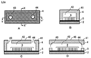
- FIGS. 1A to 1D are diagrams illustrating an example of the device 1 according to the third embodiment.
- FIG. 2 is a diagram for explaining an example of a manufacturing process of the device 1a in which the nanowire 3 is formed on the first surface of the substrate 2, which is an example of the device 1 according to the third embodiment.
- 3A to 3C are views showing various aspects of the cover member 4.
- FIG. 3D shows the substrate 2 having nanowires formed on the first surface.
- FIG. 4 is a diagram for explaining an example of a manufacturing process of the device 1b according to the fourth embodiment.
- FIG. 5 is a flowchart of the first embodiment of the extraction method.
- FIG. 6 is a flowchart of an embodiment of a storage method.
- FIG. 7 is a flowchart of an embodiment of the transfer method.
- FIG. 8A to 8E are photographs substituting for drawings, and are photographs of the devices manufactured in Examples 1 to 5, respectively.
- FIG. 9 is a graph showing the results of measuring the pore size distribution of the films produced in Examples 1, 3 and 4 by the mercury porosimetry method.
- FIG. 9A is a graph showing the distribution when the pore size scale is 1 nm to 100 nm
- FIG. 9B is a graph showing the distribution when the pore size scale is 1 nm to 100 ⁇ m.
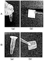
- 10A and 10B are drawing-substituting photographs, (a) a photograph of a centrifuge tube after taking out the device from the centrifuge tube after miRNA extraction, and (b) a photograph of the device taken out from the centrifuge tube.
- FIG. 11A and 11B are drawing-substituting photographs, (a) a photograph of a centrifuge tube immediately after the completion of the miRNA extraction step, (b) a photograph of a centrifuge tube after the device was taken out of the centrifuge tube after miRNA extraction, (c) a centrifuge. It is a photograph of the device taken out from the tube.
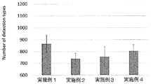
- FIG. 12 is a graph showing the types of miRNA contained in the miRNA extract extracted using the devices of Examples 1 to 4.
- FIG. 13 is a graph showing the analysis results of Examples 5 and 6 and Comparative Example 1.
- 14 is a photograph as a substitute for a drawing, and FIG. 14A is an SEM photograph before dropping saliva in Example 5. Further, FIG. 14B is an SEM photograph after dropping saliva in Example 5.
- the device disclosed in the present application is characterized by including a nanostructure capable of capturing EVs.
- the “nanostructure” means that EVs can be adsorbed by an interaction, and the specific surface area is increased as compared with the minimum area of the same kind and the same amount of material. It means a structure having an improved adsorption efficiency of EVs.
- the nanostructure can be produced, for example, by using a material having fine pores (nanopores) or by aggregating (dense) fine fibers (wires).
- the “nanopore” means a nano-sized opening having an average size of 10 nm or more and less than 1000 nm, or a fiber interval.
- nanopores when described as “with nanopores” or “including nanopores”, it has pores distributed in the nano order (1 nm or more and less than 1000 nm), and the average size of only nano order pores is 10 nm or more and 1000 nm. Means less than. Therefore, as long as the “nanopore” is included, a micro-order (1 ⁇ m or more and less than 1000 ⁇ m) pore may be included, but the micro-order pore is not a basis for calculating the average size of the “nanopore”. Further, when it is described as “without nanopores”, it means that the average size of nanopores is not included or only the nanopores are out of the above average size of “nanopores”.
- the shape of the device including the nanostructure is not particularly limited, and may be, for example, a film shape; a thread (string) shape; a columnar shape, a prismatic shape, or a three-dimensional shape such as an indefinite shape. ..
- a film shape a thread (string) shape
- a columnar shape a prismatic shape
- a three-dimensional shape such as an indefinite shape. ..
- each embodiment of the device using a film-shaped and nanowire will be described, but the device embodiment below is merely an example, and if the definition of the “nanostructure” is satisfied, the device is The present invention is not limited to the embodiments illustrated below.
- the average size of nanopores can be measured by the mercury penetration method.
- the first embodiment of the device uses a film made with cellulose nanofibers as nanostructures.
- wood fibers cellulose fibers
- This cellulose fiber is composed of a bundle of innumerable cellulose nanofibers.
- the cellulose fibers are collided with each other at high pressure in a solvent in the presence of a TEMPO catalyst to release the bundled cellulose fibers, whereby cellulose nanofibers can be obtained.
- the method for producing the cellulose nanofibers described above is merely an example, and other methods may be used.
- the device according to the first embodiment can be produced by suction-filtering the obtained solvent containing cellulose nanofibers so that the cellulose nanofibers aggregate and form a film due to surface tension.
- Water etc. are mentioned as a solvent which disperse
- the films made can be non-woven.
- the cellulose nanofibers of the produced film may have a gap (nanopore).
- the efficiency of capturing EVs can be improved by adjusting the size of the nanopore.
- the average size of the nanopores can be, for example, a lower limit value of 10 nm or more, 15 nm or more, 20 nm or more, 25 nm or more, 30 nm or more, and an upper limit value of less than 1000 nm, 500 nm or less, 200 nm or less, 100 nm or less.
- the EVs be confined in the nanopores, as shown in Examples described later.
- the size of each nanopore has a distribution, even if the average size of the nanopores is 10 nm, there are nanopores of a size capable of confining EVs.
- the lower limit of the average size of the nanopores may be, for example, 40 nm or more, 45 nm or more, 50 nm or more, 60 nm or more.
- the size of the nanopore may be measured by a mercury intrusion method, image processing or the like.
- Nanopores are obtained by adding a liquid having a low surface tension (hereinafter, also referred to as a “low surface tension solvent”) to wet cellulose nanofibers that have been aggregated by suction filtration, and then aspirate the aggregated cellulose nanofibers. It can be formed by replacing the solvent contained in the fiber mass with a low surface tension solvent and drying.
- the size of the nanopore can be adjusted by changing the low surface tension solvent added.
- the surface tension of the low surface tension solvent is not particularly limited as long as it is smaller than the surface tension of water (20 ° C., 72.75 mN / m) and is a range in which nanopores can be produced. For example, the surface tension at 20 ° C.
- the formation and size adjustment of the nanopores described above are merely examples, and the formation and size adjustment of the nanopores may be performed by other methods.
- the width of the cellulose nanofibers may be changed and the size of the nanopores may be adjusted by changing the high-pressure treatment conditions for unraveling the cellulose fibers and changing the cellulose raw material such as the type of pulp, bacteria and squirts.
- the number of captured EVs increases, and many types of miRNA can be analyzed.
- the second embodiment of the device differs from the first embodiment in that a film made of cellulose fibers (pulp) is used as a nanostructure instead of cellulose nanofibers.
- the device according to the second embodiment may be manufactured by the same procedure as in the first embodiment of the device, except that cellulose fibers (pulp) are dispersed in a solvent instead of the cellulose nanofibers.
- the gap between the cellulose fibers and the gap between the cellulose nanofibers existing on the surface of the cellulose fiber can be produced and adjusted in size by the same procedure as in the first embodiment. Since the width of the cellulose nanofiber is about 3 nm to 100 nm, nanopores having the same size as in the first embodiment are formed.
- the width of the cellulose fiber is about 20 ⁇ m to 40 ⁇ m. Therefore, the size of the gap is, unlike the first embodiment, multi-scale in the order of nm to ⁇ m, about 10 nm to 1000 nm, and about 1 ⁇ m to 100 ⁇ m.
- the devices according to the first and second embodiments can be used by cutting the produced film into an appropriate size.
- the cut device is attached to a centrifuge tube used in the miRNA extraction step described later, the EVs in a cough are captured by attaching to a mask, and the EVs in sweat can be captured by attaching to a towel or the like. May be.
- the first and second embodiments of the device are film-shaped, they may have other shapes. For example, in the case of a thread (string) shape, a mold (suction filtration filter) in which a groove is formed in a thread (string) shape at the time of suction filtration may be used.
- a solvent in which cellulose (nano) fibers are dispersed may be injected into a coagulation bath such as acetone for spinning.
- suction filtration may be performed using a mold (suction filtration filter) having a predetermined shape.
- the solvent in which the cellulose (nano) fibers are dispersed is introduced into only a part of the suction filtration filter, and a lump in which the cellulose (nano) fibers are aggregated is produced by suction filtration.
- an amorphous three-dimensional nanostructure By repeating the production of the lump in which the cellulose (nano) fibers are aggregated, an amorphous three-dimensional nanostructure can be produced.
- a three-dimensional nanostructure can also be produced by putting a solvent in which cellulose (nano) fibers are dispersed in a container having a desired shape and subjecting it to freeze-drying.
- the device may be made of only cellulose (nano) fibers, or a filler or the like may be added as long as the object of the present disclosure is not impaired.
- a filler such as polyamidoamine epichlorohydrin as a wet strength agent
- addition of nanowires see the third embodiment described later for nanowires alone, and the like can be mentioned.
- a third embodiment of the device uses nanowires as the device.
- 1A to 1D are diagrams illustrating an example of the device 1 according to the third embodiment.
- 1A is a top view of the device 1a
- FIG. 1B is a sectional view taken along line XX ′ of FIG. 1A
- FIG. 1C is a sectional view taken along line YY ′ of FIG. 1A
- 1D is a cross-sectional view of a modified example of the embodiment shown in FIG. 1C.
- the device 1a includes at least the substrate 2, the nanowires 3, and the cover member 4, and is illustrated in FIGS. 1B to 1D (hereinafter, a description common to FIG. 1 may be simply referred to as “FIG. 1”.
- the device 1a shown in () is the same as the above) includes the catalyst layer 5 for forming the nanowire 3.
- the catalyst layer 5 for forming the nanowires 3 is formed on the substrate 2, and the nanowires 3 are formed on the catalyst layer 5.
- the “first surface” means the outermost surface of the surface of the substrate 2 on which the nanowires 3 are formed. Therefore, as described later, when the “first surface” of the substrate 2 and the “second surface” of the cover member are described as being liquid-tightly adhered, the member of the “first surface” means that the substrate 2 and the catalyst layer 5 or coating layer.
- the nanowire may grow on the “first surface” that is in close contact with the “second surface” of the cover member.
- the flat portion at the root of the nanowire is referred to as the “first surface”.
- the “tip” of the nanowire means an end portion of the nanowire that is farther from the first surface of the substrate 2 among both end portions of the nanowire, and the “front end” of the first surface side of the substrate 2 The end portion of the nanowire is directly referred to as “end portion” in the present specification.
- the cover member 4 includes a cover member base material 41 and a flow path 42 formed in the cover member base material 41.
- the “second surface” is a surface of the cover member base material 41 on the side where the flow path 42 is formed (following the virtual plane when the opening of the flow path 42 is a virtual plane). Means).
- the surface of the cover member base material 41 in contact with the catalyst layer 5 corresponds to the second surface.
- the cover member 4 includes a sample input hole 43 and a sample recovery hole 44. As shown in FIG. 1C, the sample input hole 43 and the sample recovery hole 44 are formed in the cover member substrate 41 so as to penetrate the flow path 42 and the surface 45 opposite to the second surface.
- FIG. 1C shows an example in which the sample liquid is charged and collected from above the device 1 a, but the sample liquid holes 43 and the sample recovery holes 44 are located at the positions of the sample liquid that has been injected to form the nanowires 3.
- the sample solution can be recovered after passing through the above-mentioned region.
- the sample input hole 43 and the sample recovery hole 44 may be formed in the side wall of the flow channel 42.
- FIG. 2 is a diagram for explaining an example of a manufacturing process of a device 1a in which the nanowire 3 is formed on the first surface of the substrate 2, which is an example of the device 1 according to the third embodiment. Note that FIG. 2 shows a cross-sectional view taken along line XX ′ of FIG. 1A.
- the patterning of photolithography may be performed in a pattern in which the nanowire 3 is desired to grow.
- the nanowires 3 may be patterned so that the catalyst layer 5 in the region where the nanowires 3 are formed on the substrate 2 is exposed (see 3a).
- patterning or photolithography may be performed so that the catalyst layers 5 are exposed in dots at predetermined intervals (see 3b).
- the resist 6 in the patterned or drawn portion is developed and removed. (4a, 4b) The resist is removed, and the nanowire 3 is grown from the place where the catalyst layer 5 is exposed. (5a, 5b) By removing the remaining resist, the substrate 2 having the nanowires 3 formed on the catalyst layer 5 formed on the first surface can be manufactured.
- FIGS. 3A to 3C are views showing various aspects of the cover member 4.
- the cover member 4 can be easily manufactured by cutting the second surface 47 of the cover member base material 41 or pressing a convex mold against the material of the cover member base material 41.
- the sample input hole 43 and the sample recovery hole 44 may be formed by using a biopsy trepan, an ultrasonic drill or the like after the transfer.
- the cover member 4 can easily change the cross-sectional area of the flow path 42 as shown in FIGS. 3A and 3B, for example.
- FIG. 3A and 3B are views showing various aspects of the cover member 4.
- a non-planar region 46 for generating turbulent flow in the sample liquid passing therethrough can be formed on any surface of the flow channel 42.
- the non-planar region 46 is not particularly limited as long as turbulent flow can be generated in the sample liquid passing therethrough, and for example, a convex portion or the like may be formed.
- the substrate 2 (FIG. 3D) having the nanowires 3 formed on the first surface, which is manufactured by the process shown in FIG. 2, is covered with the cover member 4 having the flow path 42 having a desired cross-sectional area and shape, thereby forming the device 1a. Can be produced.
- the substrate 2 is not particularly limited as long as the catalyst layer 5 can be laminated.
- silicon, quartz glass, Pyrex (registered trademark) glass, etc. may be mentioned.
- examples of particles for producing the nanowires 3 include ZnO.
- examples of the catalyst for producing the nanowire 3 include gold, platinum, aluminum, copper, iron, cobalt, silver, tin, indium, zinc, gallium, chromium, and oxides thereof.
- the resist 6 for photolithography is not particularly limited as long as it is one generally used in the semiconductor field, such as OFPR8600LB and SU-8.
- the removing liquid for the resist 6 is not particularly limited as long as it is a removing liquid that is commonly used in the semiconductor field, such as dimethylformamide and acetone.
- the nanowire 3 may be grown from the catalyst layer 5 by a known method.
- ZnO fine particles when used as the catalyst layer 5, it can be produced by using a hydrothermal synthesis method.
- the ZnO nanowire 3 can be grown from the portion where the ZnO particles (catalyst layer 5) are exposed by immersing the ZnO nanowire 3.
- the nanowire 3 can be manufactured in the next step.
- a core nanowire is formed by using a material such as 3 , SnO 2 , Sm 2 O 3 , and EuO by a physical vapor deposition method such as pulse laser deposition and a VLS (Vapor-Liquid-Solid) method.
- (B) Using SiO 2 , TiO 2 or the like, a coating layer around the core nanowire by a general vapor deposition method such as sputtering, EB (Electron Beam) vapor deposition, PVD (Physical Vapor Deposition), ALD (Atomic Layer Deposition). To form. Note that the coating layer of (b) above is not essential and may be implemented as needed.
- the diameter of the nanowire 3 may be appropriately adjusted according to the purpose.
- the diameter of the nanowires 3 may be changed by changing the size of the ZnO particles when the ZnO particles are formed.
- the diameter can be appropriately adjusted by changing the vapor deposition time when forming the coating layer.
- the material for producing the cover member 4 is not particularly limited as long as it can cut or transfer a mold.
- thermoplastic resin such as polyethylene, polypropylene, polyvinyl chloride, polyvinylidene chloride, polystyrene, polyvinyl acetate, polytetrafluoroethylene, ABS (acrylonitrile butadiene styrene) resin, AS (acrylonitrile styrene) resin, acrylic resin (PMMA)
- thermosetting resins such as phenol resin, epoxy resin, melamine resin, urea resin, unsaturated polyester resin, alkyd resin, polyurethane, thermosetting polyimide, and silicone rubber.
- FIGS. 1 to 3 are merely examples of the device 1, and there is no particular limitation as long as the nanowire is formed on the substrate 2.
- nanowires may be formed in the channel formed on the substrate 2 by the procedure described in International Publication No. WO 2015/137427.
- the device 1b according to the fourth embodiment is different from the device 1a according to the third embodiment in that the ends of the nanowires 3 are embedded in the first surface of the substrate 2a and the material for forming the substrate 2a is different.
- the other points are the same as those of the device 1a according to the third embodiment.
- FIG. 4 is a diagram for explaining an example of a manufacturing process of the device 1b according to the fourth embodiment.
- the substrate 2 having the nanowires 3 formed on the first surface, which is manufactured by the device 1a according to the third embodiment, is prepared as a template.
- a material for forming the substrate 2a is applied to the mold.
- the substrate 2a is separated from the template to form the substrate 2a in which the nanowires 3 are partially embedded in the first surface.
- the substrate 2a in which the ends of the nanowires 3 are embedded in the first surface is manufactured.
- the growth of the nanowire 3 can be performed by the same procedure as in the first embodiment.
- the device 1b can be manufactured by covering the substrate 2a with the cover member 4 manufactured by the same procedure as in the third embodiment.
- the material forming the substrate 2a is not particularly limited as long as the nanowires 3 can be embedded, and examples thereof include the same material as the cover member 4.
- extraction method a method for capturing EVs using the above device and a method for extracting miRNA after capturing (hereinafter sometimes abbreviated as “extraction method”) will be described.
- the first embodiment of the extraction method includes an extracellular vesicle (EVs) capture step (ST1) and a miRNA extraction step (ST2).
- the extracellular vesicle (EVs) capturing step (ST1) the EVs in the sample solution are captured by the device by bringing the sample solution into contact with the device capable of capturing the EVs.
- the miRNA extraction step (ST2) EVs are crushed by bringing the device capturing EVs into contact with the crushed solution of EVs, and the miRNAs are extracted from EVs into the crushed solution.
- the sample solution is not particularly limited as long as it contains EVs, and biological samples such as blood, lymph, bone marrow fluid, semen, breast milk, amniotic fluid, urine, saliva, nasal fluid, sweat, tears, bile fluid, cerebrospinal fluid, etc.
- biological samples such as blood, lymph, bone marrow fluid, semen, breast milk, amniotic fluid, urine, saliva, nasal fluid, sweat, tears, bile fluid, cerebrospinal fluid, etc.
- a liquid is mentioned.
- the sample solution other than the biological sample solution include a cell culture supernatant, a sample solution for experiments in which EVs is added to a medium or a buffer solution, and the like.
- a biological sample solution is used as the sample solution, a non-invasive sample solution such as urine, saliva, runny nose, sweat, tears and the like is preferable in consideration of reducing the burden on the patient.
- miRNA when miRNA extracted using the device disclosed in the present application was analyzed, many types of miRNA could be analyzed. In other words, using the device disclosed in the present application, it was possible to analyze a trace amount of miRNA that could not be analyzed by the conventional method. Therefore, using the device disclosed in the present application, miRNA can be extracted in a small amount with the same type of sample liquid. Moreover, in order to fractionate and collect EVs by ultracentrifugation, a sample liquid of about several ml is required. However, for example, there are some biological sample solutions such as saliva and tears that make it a great burden on the patient to collect an amount of several ml.
- miRNA can be extracted even with a small amount of the sample liquid, as compared with the conventional method by ultracentrifugation, and thus the saliva in saliva can be extracted. It is particularly useful for extraction of miRNA contained in EVs.
- the EVs disruption solution is not particularly limited as long as EVs can be disrupted, and for example, a commercially available cell lysis buffer (Cell Lysis Buffer) may be used.
- the cell lysis buffer include cell lysis buffer M (Fuji Film Wako Pure Chemical Industries, Ltd., 038-21141), RIPA Buffer (Fuji Film Wako Pure Chemical Industries, Ltd., 182-02451), and the like.
- the time for immersing the device in the disruption solution is not particularly limited as long as EVs can be disrupted and miRNA can be taken out.
- miRNA may be directly captured by the device by flowing a solution obtained by disrupting Evs with a disruption solution into the device.
- the second embodiment of the extraction method includes a device washing step of washing the device capturing EVs between the extracellular vesicle (EVs) capturing step (ST1) and the miRNA extracting step (ST2) shown in FIG.
- the point is different from the first embodiment of the extraction method, and other points are the same as the first embodiment of the extraction method.
- a biological sample solution extracted from a living body such as saliva, sweat, or a runny nose, contains RNase, which is an enzyme that decomposes RNA of foreign substances such as viruses in order to protect the living body from viruses and the like invading from the outside.
- RNase when miRNA is extracted from a biological sample solution containing RNase such as saliva, sweat, or runny nose, RNase may be adsorbed to the device during the extracellular vesicle capturing step. Then, if the miRNA extraction step is performed with a device to which RNase is adsorbed, the miRNA extracted from EVs may be decomposed by RNase.
- the device that captured EVs is cleaned to remove RNase from the device.
- the device capturing the EVs may be immersed in a cleaning liquid for a predetermined time and cleaned.
- the washing time is not particularly limited, but if it is too short, the washing effect is reduced, and if it is too long, the captured EVs are easily peeled off, and the EVs yield may be reduced.
- the device may be immersed in the cleaning liquid for about 1 to 2000 seconds.
- the washing solution include pure water, PBS, NaCl, physiological saline, various buffer solutions such as PBS, and the like. When pure water is used as the cleaning liquid, it is desirable to set the cleaning time shorter than that of the buffer solution or the like so that the captured EVs will not burst due to the osmotic pressure.
- the embodiment of the method for analyzing miRNA includes an analysis step of analyzing miRNA in the disrupted liquid extracted by the first or second embodiment of the extraction method.
- a known miRNA analysis method may be used. For example, (1) total RNA including miRNA is extracted using miRNeasy Mini Kit (QIAGEN), and comprehensive analysis is performed from about 2500 kinds of miRNA using 3D-Gene (registered trademark) miRNA chip, and the chip is analyzed.
- the miRNeasy Serum / Plasma kit (Qiagen) is used to quantify the image, calculate the expression ratio, perform variable gene analysis, and perform cluster analysis, and isolate the total miRNA in the disrupted solution, and then use the miScript II RT Kit (Qiagen).
- the sample solution is dropped on the film or the film is immersed in the sample solution. do it.
- the sample solution is introduced from the sample introduction hole in the extracellular vesicle capturing step (ST1). do it.
- the film may be immersed in the disruption solution in the miRNA extraction step (ST2).
- the miRNA extraction step (ST2) the crushed solution is introduced from the sample introduction hole to extract the extracted miRNA. It is sufficient to collect the crushed liquid containing it.
- the cover member 4 is formed in the devices 1a and 1b according to the third and fourth embodiments, the cover member 4 may not be provided.
- the sample solution in the extracellular vesicle trapping step (ST1), the sample solution may be dropped onto the nanowire, or the device may be immersed so that the nanowire comes into contact with the container containing the sample solution.
- the nanowire portion in the miRNA extraction step (ST2), the nanowire portion may be immersed in the container containing the disrupted solution.
- the nanowires 3 are formed on the first surface of the substrate in the devices 1a and 1b according to the third and fourth embodiments, the nanowires 3 may be used alone.
- the nanowire in the extracellular vesicle capturing step (ST1), the nanowire may be brought into contact with the sample solution by introducing the nanowire into a tube or the like containing the sample solution.
- the miRNA extraction step (ST2) the sample solution may be removed from the tube, and then the disrupted solution may be added to the tube.
- miRNA can be directly extracted from EVs captured in the device.
- the nanowire 3 may be collected from the first surface of the substrate.
- the devices shown in the above embodiments can capture EVs in the sample liquid.
- the device When EVs are crushed with a crushing solution and the extracted miRNA is comprehensively analyzed, if the device is destroyed by the crushing solution, the destroyed residue may adversely affect the analysis process. Therefore, the device should be durable to the disrupted liquid, for example, at least 5 minutes, preferably 30 minutes or more, to the disrupted liquid.
- the film composed of nanowires or cellulose nanofibers is more preferable because it has durability against the crushing liquid.
- the above device is merely an example, and is not limited to the device of the above embodiment as long as it can adsorb EVs (preferably has durability against the crushed liquid).
- a porous material having many small holes on the surface.
- specific examples thereof include microporous materials such as activated carbon and zeolite, mesoporous materials such as silicon dioxide (mesoporous silica) and aluminum oxide, and macroporous materials such as pumice.
- a filter made of molten glass or polymer may be used.
- FIG. 6 is a flowchart of an embodiment of a storage method.
- the embodiment of the storage method includes an extracellular vesicle capturing step (ST11), a drying step (ST12), and a storage step (ST13).
- the extracellular vesicle capturing step (ST11) is performed using a device containing nanopores as a device.
- the extracellular vesicle capturing step (ST11) may be performed using the same procedure and sample solution as the extracellular vesicle capturing step (ST1) of the first embodiment of the extraction method, except that a device containing nanopores is used. Good.
- the drying step (ST12) the liquid of the sample liquid impregnated in the device is removed.
- the amount of sample liquid may be small. Therefore, the drying step may be performed by natural drying in which the liquid is evaporated at room temperature.
- the device that has captured the extracellular vesicles and dried in the drying step (ST12) is stored.
- the difference in storage temperature for example, the extracellular vesicles when stored at refrigeration (4 ° C.) and stored at room temperature.
- room temperature refers to, for example, 10 ° C to 30 ° C, and may be more than 15 ° C and 30 ° C or less.
- FIG. 7 is a flowchart of an embodiment of the transfer method.
- the embodiment of the transfer method includes an extracellular vesicle capturing step (ST21), a drying step (ST22), and a transfer step (ST23).
- the extracellular vesicle capturing step (ST21) and the drying step (ST22) are the same as the extracellular vesicle capturing step (ST11) and the drying step (ST12) of the above-mentioned storage method. Therefore, detailed description is omitted to avoid duplication of description.
- the device that has captured the extracellular vesicles dried in the drying step (ST22) is transferred.
- the temperature during preservation does not significantly affect the accuracy of analysis. Therefore, by contacting a device with a biological sample collected from a patient at a local medical institution, drying it, and then transferring the device to a medical institution having a function of analyzing extracellular vesicles by mail etc.
- a film-like device having nanopores was produced from cellulose nanofibers by the following procedure.
- (2) Hydrophilic polytetrafluoroethylene (PTFE) was prepared from the above nanocellulose aqueous dispersion using a filtration device (KG-90, Advantech Toyo Roshi Kaisha, Ltd.) and a suction device (Aspirator AS-01, AS ONE Corp.).
- Example 1 The device of Example 1 was produced by cutting the produced film into a square having a side of 1 cm.
- FIG. 8A is an SEM photograph of the film produced in Example 1.
- FIG. 9 is a graph showing the results of measuring the pore size distribution of the produced film by the mercury porosimetry method.
- FIG. 9A is a graph showing the distribution when the pore size scale is 1 nm to 100 nm
- FIG. 9B is a graph showing the distribution when the pore size scale is 1 nm to 100 ⁇ m. From FIGS. 9A and 9B, it was confirmed that the film prepared in Example 1 had a distribution of nanopores of about 4 nm to 300 nm and an average size of about 60 nm.
- Example 2 A film-like device was produced from cellulose nanofibers by the same procedure as in Example 1 except that the step of replacing with t BuOH in Example 1 was not performed.
- FIG. 8B is an SEM photograph of the film produced in Example 2. From the photograph, in the device prepared in Example 2, formation of nanopores was not observed between the cellulose nanofibers. Since the nanopores do not exist at all, the size of the nanopores in Example 2 is considered to be 1 nm.
- a film-like device having micro-sized pores was produced from pulp (cellulose fiber) by the following procedure.
- Example 3 was produced by cutting the produced film into a square having a side of 1 cm.
- FIG. 8C is a photograph of the film made in Example 3.
- 9A and 9B show the pore size distribution measured by the mercury porosimetry. As is clear from FIGS. 9A and 9B, the pore size of the produced film was about 7 nm to 100 nm and about 1 ⁇ m to 100 ⁇ m in multiscale.
- Example 4 A film-like device was produced from pulp (cellulose fiber) by the same procedure as in Example 3 except that the substitution step with t BuOH in Example 3 was not performed.
- FIG. 8D is a photograph of the film made in Example 4.
- 9A and 9B show the pore size distribution measured by the mercury porosimetry. As is clear from FIGS. 9A and 9B, the pore size of the produced film was about 1 ⁇ m to 100 ⁇ m.
- a device in which nanowires were embedded in a flow channel formed on a substrate was manufactured by the following procedure.
- a Si (100) substrate (Advantech Co., Ltd.) was subjected to channel patterning of a PDMS-embedded nanowire device.
- a positive resist (OFPR-8600 LB, Tokyo Ohka Kogyo Co. Ltd.) was spin-coated on a Si substrate surface by a spin coater (MS-A100, Mikasa Co., Ltd.) under the conditions of 500 rpm (5 sec) and 3000 rpm (120 sec).
- the resist was fixed on the substrate by evaporating the solvent by heating at 90 ° C. for 12 minutes on a hot plate.
- a glass mask was placed on the heated substrate, and the resist was softened by irradiating with 600 mJ / cm 2 i-line by an exposure machine. Finally, this substrate was immersed in a developing solution (NMD-3, Tokyo Ohka Kogyo Co., Ltd.) for about 10 seconds to peel off the softened resist, and the substrate was taken out from the developing solution and washed with running water. Next, patterning was completed by heating at 90 ° C. for 5 minutes on a hot plate.
- a developing solution NMD-3, Tokyo Ohka Kogyo Co., Ltd.
- a Cr layer to be a seed layer for nanowire growth was formed on the substrate surface.
- the conditions of the sputtering apparatus (EIS-200ERT-YN, Elionix Co., Ltd.) for producing a Cr layer were 1.2 ⁇ 10 ⁇ 2 Pa and 14 min, and a 135 nm Cr layer was deposited.
- This substrate was immersed in 2-propanol warmed to 70 ° C. for 40 minutes on a hot plate, and then ultrasonically treated for 2 minutes by an ultrasonic device to roughly remove the resist outside the channel. After that, the substrate was transferred to 2-propanol at 70 ° C. placed in another container, immersed for 10 minutes, and then subjected to ultrasonic treatment for 1 minute to completely remove the resist outside the channel.
- the fine Cr particles on the substrate were removed by rinsing with 70 ° C. 2-propanol placed in another container.
- the Cr layer was deposited only on the flow path portion on the substrate. This substrate was heated in an electric furnace at 400 ° C. for 2 hours to oxidize the Cr layer and complete the production of the seed layer for nanowire growth.
- HMTA Hexamethylenetetramine
- HMTA Hexamethylenetetramine
- a stirrer for 7 min.
- zinc nitrate hexahydrate 12323, Alfa Aesar
- the mixture was stirred for 7 minutes to prepare a nanowire growth solution.
- the nanowires were grown by immersing in air and heating at 95 ° C. for 3 hours in a constant temperature and high temperature device for blowing air. After that, the substrate was taken out of the beaker and washed with ultrapure water to remove the non-specifically grown nanowires.
- the substrate on which the nanowire produced in (3) above was grown was attached onto a petri dish.
- PDMS prepolymer (Silpot 184, Dow Corning Toray Ind., Ltd.) and curing agent (Silpot 184 CAT, Dow Corning Toray Ind., Ltd.) were placed in the container at a weight ratio of 10: 1.
- the mixture was poured under the conditions of 2000 rpm, 2 min, 2200 rpm, and 6 min. Bubbles in the polymer were removed by vacuuming this for 2 h, and then heating was performed for 2 h on a hot plate at 80 ° C. to promote polymerization and cure the polymer.
- the nanowire on the Si substrate was embedded in PDMS.
- the PDMS in which the nanowires were embedded was peeled off from the Si substrate, and the PDMS-embedded nanowires were attached to a slide glass. Then, the PDMS-embedded nanowire was grown under the same conditions as in (3) above. After the growth, the embedded nanowire was taken out from the beaker, and the nonspecifically grown nanowire was washed away with ultrapure water to remove it, thereby completing the production of the PDMS embedded nanowire.
- FIG. 8E is an enlarged photograph of the nanowire of the device manufactured in Example 5.
- FIG. 10A is a photograph when using the device of Example 1, (a) a photograph of the centrifuge tube after taking out the device from the centrifuge tube after miRNA extraction, and (b) a photograph of the device taken out from the centrifuge tube.
- FIG. 10B is a photograph when the device of Example 2 was used, (a) a photograph of the centrifuge tube after taking out the device from the centrifuge tube after miRNA extraction, and (b) a photograph of the device taken out from the centrifuge tube.
- FIG. 11A is a photograph when using the device of Example 3, (a) a photograph of the centrifuge tube immediately after the completion of the miRNA extraction step, (b) a photograph of the centrifuge tube after the device was taken out of the centrifuge tube after miRNA extraction, (C) A photograph of the device taken out from the centrifuge tube.
- FIG. 11A is a photograph when using the device of Example 3, (a) a photograph of the centrifuge tube immediately after the completion of the miRNA extraction step, (b) a photograph of the centrifuge tube after the device was taken out of the centrifuge tube after miRNA extraction, (C) A photograph of the device taken out from the centrifuge tube.
- 11B is a photograph when the device of Example 4 was used, (a) a photograph of the centrifuge tube immediately after the completion of the miRNA extraction step, (b) a photograph of the centrifuge tube after the device was taken out from the centrifuge tube after miRNA extraction, (C) A photograph of the device taken out from the centrifuge tube.
- FIG. 10A and FIG. 10B when the device made from the cellulose nanofibers of Example 1 and Example 2 was used, even after the EVs were crushed by the crushing liquid, the fiber derived from the device or the like was placed in the centrifuge tube. Was not seen, and the removed device retained its original shape. Therefore, after extracting the miRNA, the miRNA extract could be prepared simply by removing the device with tweezers.
- Example 3 and Example 4 when the device made from the pulp (cellulosic fiber) of Example 3 and Example 4 was used, fibers separated from the device were observed in the centrifuge tube and were taken out. The device was partially defective. Therefore, in Examples 3 and 4, the fibers derived from the device, which interfere as an impurity in the miRNA analysis described later, were removed by centrifugation.
- the type of miRNA contained in the miRNA extract was analyzed using a 3D-Gene (registered trademark) (manufactured by Toray Industries, Inc.) human miRNA chip according to the following procedure.
- A The miRNA extract was purified using a SeraMi Exosome RNA purification column kit (System Biosciences Inc.) according to the instruction manual of the kit manufacturer.
- B 15 ⁇ l of the purified miRNA extract was added to a microarray and 3D-Gene Human miRNA Oligo chip ver. 21 (Toray Industries) was used to analyze miRNA profiling.
- 3D-Gene contains a 2565 human miRNA probe, and the expression of up to 2565 types of miRNA can be analyzed from the miRNA extract.
- C The expression level of each miRNA in the miRNA extract was analyzed by calculating the signal intensity after subtracting the background of all miRNAs in each microarray, and then performing global normalization.
- FIG. 12 is a graph showing the types of miRNA contained in the miRNA extract extracted using the devices of Examples 1 to 4.
- each example is an average value of three analysis results.
- FIG. 12 it was confirmed that miRNA can be directly extracted from the EVs captured in the device when any of the devices of Examples 1 to 4 is used.
- FIGS. 10 and 11 in the devices produced from the pulps of Examples 3 and 4, a part of the device was lost during the crushing of EVs, and fibers separated from the device were observed in the centrifuge tube. Was given. Therefore, it was revealed that the devices of Example 1 and Example 2 are preferable when the miRNA analysis is performed subsequent to the extraction of the miRNA from the sample solution.
- Non-Patent Document 2 in the conventional method for separating EVs by subjecting saliva to ultracentrifugation and analyzing miRNA, in Non-Patent Document 2 described above, there were 27 types as described on page 10. Further, in Non-Patent Document 3 described above, FIG. As described in 7, the number of miRNAs that could be analyzed was 93. In addition, in the method described in Non-Patent Document 3, it is described that saliva of 5 ml or 15 ml is also used, but it is a burden on the subject (patient) to collect such a large amount of saliva. Is very large. On the other hand, when the devices described in Examples 1 to 4 were used, more than 700 types of miRNA were successfully analyzed using only 10 ⁇ l of saliva. In other words, it means that it was possible to analyze even a small amount of miRNA.
- the work of extracting miRNA from EVs in saliva sample liquid is performed.
- the procedure can be simplified.
- miRNA can be directly extracted from a device that captures EVs (and EVs in saliva can be captured in the device at a high rate), so that loss during miRNA extraction work is reduced and highly accurate miRNA analysis can be performed. I confirmed the effect. Therefore, the miRNA extraction method disclosed in the present application is very useful as a sample preparation method in the analysis method of miRNA contained in a sample solution.
- the device described in the first to fourth embodiments can be used for medical examinations and the like. By touching the tongue, it is expected that cancer diagnosis will be performed at the same time.
- Example 2 Urine was used as the sample liquid, the device prepared in Example 5 was used as the device, and miRNA was extracted and analyzed from EVs contained in the urine by the following procedure.
- sample 1 mL of commercially available urine Proteogenex, Bioreclamation IVT, EW Biopharma
- the centrifuge tube was set in a cooling centrifuge at 3000 xg, 15 min, 4 ° C.
- Impurities were precipitated by centrifugation at the conditions.
- the supernatant portion from which the impurities are removed will be referred to as a urine sample.
- miRNA could be directly extracted from EVs captured on the nanowire.
- the analyzed miRNAs were 171, 261, and 352 kinds.
- ExoQuick manufactured by Funakoshi Co., Ltd.
- the types of miRNAs that could be analyzed were 337, 355, and 491.
- Example 6 [Effects of storage temperature and period of device capturing extracellular vesicles on analysis of extracellular vesicles] ⁇ Example 6> Using the device (cellulose nanofiber; with nanopore) produced in Example 1, an experiment was conducted in the following procedure. (1) Preparation of sample liquid Saliva was collected from a subject. Impurities were removed by putting the collected saliva in a centrifuge tube and centrifuging at 3000 g for 15 minutes. (2) Capture of EVs in Sample Saliva sample 10 ⁇ l was dropped on the device and left for about 10 seconds to capture EVs in the saliva sample on the device. (3) Drying of Device The device on which the saliva sample was dropped was dried by leaving it at room temperature for 10 seconds.
- Example 7 An experiment was conducted in the same procedure as in Example 5 except that the storage temperature was 4 ° C.
- FIG. 13 is a graph showing the results of Examples 5 and 6 and Comparative Example 1. As shown in the graph, in comparison with the case of using the device with nanopores (Examples 5 and 6) and the case of using the device without nanopores (Comparative Example 1), the storage stability was observed after the second day. It showed a remarkable effect. In addition, when a device with nanopores is used, the influence of the storage temperature, more specifically, the difference between room temperature (Example 5) and 4 ° C. (Example 6) on the analysis accuracy of extracellular vesicles is particularly large. I could't see it.
- FIG. 14A is a SEM photograph before dropping saliva in Example 5.
- FIG. 14B is an SEM photograph after saliva was dropped and dried in Example 5.
- a large number of nanopores were formed on the surface of the device prepared from the cellulose nanofibers subjected to the step of displacing with a medium having a low surface tension such as t BuOH in Example 1.
- nanopores were closed on the surface of the device after the saliva was dropped and dried. This is probably because the surface tension of saliva, which is a water-based sample, is higher than that of t BuOH, and therefore the force of closing the nanopores acted in the process of drying saliva (the arrow in FIG. 14B partially shows). Exposed EVs are shown.). As shown in FIG. 13, it is considered that the storage stability is increased when the device manufactured in Example 1 is used because EVs are confined between the cellulose nanofiber fibers and the contact with air is reduced. ..
- miRNA can be easily and accurately extracted and analyzed from a sample solution. Therefore, it is useful for cell experiments and the like in medical institutions, universities, companies, research institutions and the like.
Abstract
La présente invention concerne un dispositif de capture efficace d'EV avec une procédure d'opération simple. Selon la présente invention, l'invention concerne, par exemple, un dispositif qui doit être utilisé pour capturer des vésicules extracellulaires dans une solution d'échantillon et qui comprend une nanostructure pour capturer des vésicules extracellulaires.
Priority Applications (4)
| Application Number | Priority Date | Filing Date | Title |
|---|---|---|---|
| US17/289,282 US20220026323A1 (en) | 2018-10-30 | 2019-10-30 | Device to be used for capturing extracellular vesicles, and preservation method and transport method for extracellular vesicles |
| CN201980071256.2A CN113039262B (zh) | 2018-10-30 | 2019-10-30 | 用于捕捉细胞外囊泡的器件、细胞外囊泡的保存方法和转送方法 |
| JP2020553962A JP7426725B2 (ja) | 2018-10-30 | 2019-10-30 | 細胞外小胞を捕捉するために用いられるデバイス、細胞外小胞の保存方法および移送方法 |
| EP19879501.5A EP3875570A4 (fr) | 2018-10-30 | 2019-10-30 | Dispositif destiné à être utilisé pour la capture de vésicules extracellulaires, et procédé de conservation et procédé de transport de vésicules extracellulaires |
Applications Claiming Priority (4)
| Application Number | Priority Date | Filing Date | Title |
|---|---|---|---|
| JP2018203526 | 2018-10-30 | ||
| JP2018-203526 | 2018-10-30 | ||
| JP2019036490 | 2019-02-28 | ||
| JP2019-036490 | 2019-02-28 |
Publications (1)
| Publication Number | Publication Date |
|---|---|
| WO2020090859A1 true WO2020090859A1 (fr) | 2020-05-07 |
Family
ID=70463782
Family Applications (1)
| Application Number | Title | Priority Date | Filing Date |
|---|---|---|---|
| PCT/JP2019/042498 WO2020090859A1 (fr) | 2018-10-30 | 2019-10-30 | Dispositif destiné à être utilisé pour la capture de vésicules extracellulaires, et procédé de conservation et procédé de transport de vésicules extracellulaires |
Country Status (5)
| Country | Link |
|---|---|
| US (1) | US20220026323A1 (fr) |
| EP (1) | EP3875570A4 (fr) |
| JP (1) | JP7426725B2 (fr) |
| CN (1) | CN113039262B (fr) |
| WO (1) | WO2020090859A1 (fr) |
Cited By (1)
| Publication number | Priority date | Publication date | Assignee | Title |
|---|---|---|---|---|
| WO2023219095A1 (fr) * | 2022-05-11 | 2023-11-16 | Craif株式会社 | Procédé de séparation d'une substance cible contenue dans un liquide cible |
Citations (2)
| Publication number | Priority date | Publication date | Assignee | Title |
|---|---|---|---|---|
| WO2015137427A1 (fr) | 2014-03-12 | 2015-09-17 | 国立大学法人名古屋大学 | Puce d'extraction de biomolécules et procédé de fabrication d'une puce d'extraction de biomolécules |
| WO2017154951A1 (fr) * | 2016-03-09 | 2017-09-14 | 国立大学法人名古屋大学 | Procédé de récupération de vésicules extracellulaires |
Family Cites Families (12)
| Publication number | Priority date | Publication date | Assignee | Title |
|---|---|---|---|---|
| US20120045487A1 (en) | 2009-04-29 | 2012-02-23 | The Regents Of The University Of Michigan | Multiphasic microfibers for spatially guided cell growth |
| CN103476924A (zh) | 2011-04-15 | 2013-12-25 | 普拉里斯坦有限公司 | 收获细胞的方法和系统 |
| US10130946B2 (en) * | 2011-09-30 | 2018-11-20 | The Regents Of The University Of Michigan | System for detecting rare cells |
| GB201202138D0 (en) * | 2012-02-07 | 2012-03-21 | Electrospinning Company The Ltd | Multi-well plate |
| CU24137B1 (es) * | 2012-03-30 | 2015-12-23 | Ct Nac Biopreparados | Método para la detección, recuperación, identificación y enumeración simultánea de microorganismos |
| CN104662424A (zh) * | 2012-07-31 | 2015-05-27 | 加利福尼亚大学董事会 | 在纳米结构装置上选择性捕获并经刺激释放循环细胞 |
| WO2014034146A1 (fr) * | 2012-09-03 | 2014-03-06 | 三菱レイヨン株式会社 | Module de culture cellulaire |
| KR20140050465A (ko) * | 2012-10-19 | 2014-04-29 | 포항공과대학교 산학협력단 | 다공성 중합체 모노리드 필터를 포함하는 체액으로부터 세포밖 소포를 분리하기 위한 장치 |
| CN105026911B (zh) * | 2013-01-03 | 2019-01-22 | 外来体诊断公司 | 用于分离微囊泡的方法 |
| EP3623792B1 (fr) * | 2014-07-09 | 2021-09-01 | Exosome Diagnostics, Inc. | Procédés pour isoler des microvésicules et extraire des acides nucléiques à partir d'échantillons biologiques |
| US10900896B2 (en) * | 2015-09-18 | 2021-01-26 | Redbud Labs, Inc. | Flow cells utilizing surface-attached structures, and related systems and methods |
| CN108633877A (zh) * | 2018-05-17 | 2018-10-12 | 广东芙金干细胞再生医学有限公司 | 一种人脐带间充质干细胞外泌体冻干粉及其制备的方法 |
-
2019
- 2019-10-30 CN CN201980071256.2A patent/CN113039262B/zh active Active
- 2019-10-30 US US17/289,282 patent/US20220026323A1/en active Pending
- 2019-10-30 JP JP2020553962A patent/JP7426725B2/ja active Active
- 2019-10-30 EP EP19879501.5A patent/EP3875570A4/fr active Pending
- 2019-10-30 WO PCT/JP2019/042498 patent/WO2020090859A1/fr unknown
Patent Citations (2)
| Publication number | Priority date | Publication date | Assignee | Title |
|---|---|---|---|---|
| WO2015137427A1 (fr) | 2014-03-12 | 2015-09-17 | 国立大学法人名古屋大学 | Puce d'extraction de biomolécules et procédé de fabrication d'une puce d'extraction de biomolécules |
| WO2017154951A1 (fr) * | 2016-03-09 | 2017-09-14 | 国立大学法人名古屋大学 | Procédé de récupération de vésicules extracellulaires |
Non-Patent Citations (6)
| Title |
|---|
| "Identify "cancer" from urinary microRNA", UNIVERSITY KYUSHU UNIVERSITY NATIONAL CANCER CENTER JAPAN, 16 December 2017 (2017-12-16), XP055705302, Retrieved from the Internet <URL:https://www.jst.go.jp/pr/announce/20171216/index.html> * |
| AMANDA MICHAEL ET AL.: "Exosomes from Human Saliva as a Source of microRNA Biomarkers", ORAL DIS, vol. 16, no. l, January 2010 (2010-01-01), pages 34 - 38 |
| KAZUYA IWAI ET AL.: "Isolation of human salivary extracellular vesicles by iodixanol density gradient ultracentrifugation and their characterizations", JOURNAL OF EXTRACELLULAR VESICLES, vol. 5, 2016, pages 30829, XP055479210, Retrieved from the Internet <URL:http://dx.doi.org/10.3402/jev.v5.30829> DOI: 10.3402/jev.v5.30829 |
| See also references of EP3875570A4 |
| SONIA A. MELO ET AL.: "Cancer Exosomes Perform Cell-Independent MicroRNA Biogenesis and Promote Tumorigenesis", CANCER CELL, vol. 26, 10 November 2014 (2014-11-10), pages 707 - 721, XP029094863, Retrieved from the Internet <URL:http://dx.doi.org/10.1016/j.ccell.2014.09.005> DOI: 10.1016/j.ccell.2014.09.005 |
| YASUI TAKAO ET AL.: "Unveiling massive numbers of cancer-related urinary- microRNA candidates via nanowires", SCIENCE ADVANCES, vol. 3, no. 12, 15 December 2017 (2017-12-15), pages e1701133, XP055705304, Retrieved from the Internet <URL:https://advances.sciencemag.org/content/3/12/e1701133/tab-pdf> * |
Cited By (1)
| Publication number | Priority date | Publication date | Assignee | Title |
|---|---|---|---|---|
| WO2023219095A1 (fr) * | 2022-05-11 | 2023-11-16 | Craif株式会社 | Procédé de séparation d'une substance cible contenue dans un liquide cible |
Also Published As
| Publication number | Publication date |
|---|---|
| JP7426725B2 (ja) | 2024-02-02 |
| CN113039262A (zh) | 2021-06-25 |
| EP3875570A4 (fr) | 2022-08-24 |
| JPWO2020090859A1 (ja) | 2021-10-07 |
| US20220026323A1 (en) | 2022-01-27 |
| CN113039262B (zh) | 2024-02-06 |
| EP3875570A1 (fr) | 2021-09-08 |
Similar Documents
| Publication | Publication Date | Title |
|---|---|---|
| WO2020090860A1 (fr) | Procédé d'extraction de miarn et procédé d'analyse de miarn | |
| Dong et al. | Nanostructured substrates for detection and characterization of circulating rare cells: from materials research to clinical applications | |
| US11613115B2 (en) | Polymer microfilters and methods of manufacturing the same | |
| Li et al. | Rational design of materials interface for efficient capture of circulating tumor cells | |
| Li et al. | Efficient capture and high activity release of circulating tumor cells by using TiO2 nanorod arrays coated with soluble MnO2 nanoparticles | |
| JP6096769B2 (ja) | 相転移媒体を有したフィルター支持 | |
| CN105331516B (zh) | 稀有细胞富集装置和方法 | |
| US20140315295A1 (en) | Polymer microfilters, devices comprising the same, methods of manufacturing the same, and uses thereof | |
| Cui et al. | ZnO nanowire-integrated bio-microchips for specific capture and non-destructive release of circulating tumor cells | |
| Hui et al. | Self-Sterilizing and regeneratable microchip for the precise capture and recovery of viable circulating tumor cells from patients with cancer | |
| US20180297039A1 (en) | Magnetic Separation Filters and Microfluidic Devices Using Magnetic Separation Filters | |
| JP2020103274A (ja) | 生体分子抽出用チップ、及び生体分子抽出用チップの製造方法 | |
| US11571695B2 (en) | Fluidic device and method for separating biomolecules | |
| WO2020090859A1 (fr) | Dispositif destiné à être utilisé pour la capture de vésicules extracellulaires, et procédé de conservation et procédé de transport de vésicules extracellulaires | |
| US11860157B2 (en) | Polymer microfilters, devices comprising the same, methods of manufacturing the same, and uses thereof | |
| Makarova et al. | Polymer microfilters with nanostructured surfaces for the culture of circulating cancer cells | |
| US20220082561A1 (en) | Methods to capture cells based on preferential adherence | |
| Wu et al. | Cell spreading behaviors on hybrid nanopillar and nanohole arrays | |
| CN113226512B (zh) | 从生物学样品中分离干细胞的膜、所述膜的生产方法以及包含所述膜的分离方法和装置 | |
| KR101150840B1 (ko) | 검체 시료의 응집용 조성물, 이를 이용한 파라핀 블록의 제작방법 및 상기 파라핀 블록을 이용한 검체 시료의 현미경 관찰방법 | |
| CN114199835B (zh) | 一种循环肿瘤细胞的检测方法及其应用 | |
| TWM583855U (zh) | 具有不平整結構的微流道晶片及微流道結構 | |
| Loeian | LIQUID BIOPSY USING THE NANOTUBE-CTC CHIP | |
| WO2023219095A1 (fr) | Procédé de séparation d'une substance cible contenue dans un liquide cible |
Legal Events
| Date | Code | Title | Description |
|---|---|---|---|
| 121 | Ep: the epo has been informed by wipo that ep was designated in this application |
Ref document number: 19879501 Country of ref document: EP Kind code of ref document: A1 |
|
| ENP | Entry into the national phase |
Ref document number: 2020553962 Country of ref document: JP Kind code of ref document: A |
|
| NENP | Non-entry into the national phase |
Ref country code: DE |
|
| ENP | Entry into the national phase |
Ref document number: 2019879501 Country of ref document: EP Effective date: 20210531 |