WO2020090859A1 - Device to be used for capturing extracellular vesicles, and preservation method and transport method for extracellular vesicles - Google Patents
Device to be used for capturing extracellular vesicles, and preservation method and transport method for extracellular vesicles Download PDFInfo
- Publication number
- WO2020090859A1 WO2020090859A1 PCT/JP2019/042498 JP2019042498W WO2020090859A1 WO 2020090859 A1 WO2020090859 A1 WO 2020090859A1 JP 2019042498 W JP2019042498 W JP 2019042498W WO 2020090859 A1 WO2020090859 A1 WO 2020090859A1
- Authority
- WO
- WIPO (PCT)
- Prior art keywords
- evs
- mirna
- extracellular vesicles
- sample
- capturing
- Prior art date
Links
Images


Classifications
-
- C—CHEMISTRY; METALLURGY
- C12—BIOCHEMISTRY; BEER; SPIRITS; WINE; VINEGAR; MICROBIOLOGY; ENZYMOLOGY; MUTATION OR GENETIC ENGINEERING
- C12M—APPARATUS FOR ENZYMOLOGY OR MICROBIOLOGY; APPARATUS FOR CULTURING MICROORGANISMS FOR PRODUCING BIOMASS, FOR GROWING CELLS OR FOR OBTAINING FERMENTATION OR METABOLIC PRODUCTS, i.e. BIOREACTORS OR FERMENTERS
- C12M23/00—Constructional details, e.g. recesses, hinges
- C12M23/02—Form or structure of the vessel
- C12M23/10—Petri dish
-
- G—PHYSICS
- G01—MEASURING; TESTING
- G01N—INVESTIGATING OR ANALYSING MATERIALS BY DETERMINING THEIR CHEMICAL OR PHYSICAL PROPERTIES
- G01N1/00—Sampling; Preparing specimens for investigation
- G01N1/28—Preparing specimens for investigation including physical details of (bio-)chemical methods covered elsewhere, e.g. G01N33/50, C12Q
- G01N1/40—Concentrating samples
- G01N1/4077—Concentrating samples by other techniques involving separation of suspended solids
-
- C—CHEMISTRY; METALLURGY
- C08—ORGANIC MACROMOLECULAR COMPOUNDS; THEIR PREPARATION OR CHEMICAL WORKING-UP; COMPOSITIONS BASED THEREON
- C08L—COMPOSITIONS OF MACROMOLECULAR COMPOUNDS
- C08L1/00—Compositions of cellulose, modified cellulose or cellulose derivatives
- C08L1/02—Cellulose; Modified cellulose
-
- C—CHEMISTRY; METALLURGY
- C12—BIOCHEMISTRY; BEER; SPIRITS; WINE; VINEGAR; MICROBIOLOGY; ENZYMOLOGY; MUTATION OR GENETIC ENGINEERING
- C12N—MICROORGANISMS OR ENZYMES; COMPOSITIONS THEREOF; PROPAGATING, PRESERVING, OR MAINTAINING MICROORGANISMS; MUTATION OR GENETIC ENGINEERING; CULTURE MEDIA
- C12N15/00—Mutation or genetic engineering; DNA or RNA concerning genetic engineering, vectors, e.g. plasmids, or their isolation, preparation or purification; Use of hosts therefor
- C12N15/09—Recombinant DNA-technology
- C12N15/10—Processes for the isolation, preparation or purification of DNA or RNA
- C12N15/1003—Extracting or separating nucleic acids from biological samples, e.g. pure separation or isolation methods; Conditions, buffers or apparatuses therefor
- C12N15/1006—Extracting or separating nucleic acids from biological samples, e.g. pure separation or isolation methods; Conditions, buffers or apparatuses therefor by means of a solid support carrier, e.g. particles, polymers
-
- D—TEXTILES; PAPER
- D04—BRAIDING; LACE-MAKING; KNITTING; TRIMMINGS; NON-WOVEN FABRICS
- D04H—MAKING TEXTILE FABRICS, e.g. FROM FIBRES OR FILAMENTARY MATERIAL; FABRICS MADE BY SUCH PROCESSES OR APPARATUS, e.g. FELTS, NON-WOVEN FABRICS; COTTON-WOOL; WADDING ; NON-WOVEN FABRICS FROM STAPLE FIBRES, FILAMENTS OR YARNS, BONDED WITH AT LEAST ONE WEB-LIKE MATERIAL DURING THEIR CONSOLIDATION
- D04H1/00—Non-woven fabrics formed wholly or mainly of staple fibres or like relatively short fibres
- D04H1/40—Non-woven fabrics formed wholly or mainly of staple fibres or like relatively short fibres from fleeces or layers composed of fibres without existing or potential cohesive properties
- D04H1/42—Non-woven fabrics formed wholly or mainly of staple fibres or like relatively short fibres from fleeces or layers composed of fibres without existing or potential cohesive properties characterised by the use of certain kinds of fibres insofar as this use has no preponderant influence on the consolidation of the fleece
- D04H1/425—Cellulose series
-
- G—PHYSICS
- G01—MEASURING; TESTING
- G01N—INVESTIGATING OR ANALYSING MATERIALS BY DETERMINING THEIR CHEMICAL OR PHYSICAL PROPERTIES
- G01N1/00—Sampling; Preparing specimens for investigation
- G01N1/28—Preparing specimens for investigation including physical details of (bio-)chemical methods covered elsewhere, e.g. G01N33/50, C12Q
- G01N1/40—Concentrating samples
- G01N1/405—Concentrating samples by adsorption or absorption
-
- B—PERFORMING OPERATIONS; TRANSPORTING
- B82—NANOTECHNOLOGY
- B82Y—SPECIFIC USES OR APPLICATIONS OF NANOSTRUCTURES; MEASUREMENT OR ANALYSIS OF NANOSTRUCTURES; MANUFACTURE OR TREATMENT OF NANOSTRUCTURES
- B82Y35/00—Methods or apparatus for measurement or analysis of nanostructures
-
- B—PERFORMING OPERATIONS; TRANSPORTING
- B82—NANOTECHNOLOGY
- B82Y—SPECIFIC USES OR APPLICATIONS OF NANOSTRUCTURES; MEASUREMENT OR ANALYSIS OF NANOSTRUCTURES; MANUFACTURE OR TREATMENT OF NANOSTRUCTURES
- B82Y40/00—Manufacture or treatment of nanostructures
-
- B—PERFORMING OPERATIONS; TRANSPORTING
- B82—NANOTECHNOLOGY
- B82Y—SPECIFIC USES OR APPLICATIONS OF NANOSTRUCTURES; MEASUREMENT OR ANALYSIS OF NANOSTRUCTURES; MANUFACTURE OR TREATMENT OF NANOSTRUCTURES
- B82Y5/00—Nanobiotechnology or nanomedicine, e.g. protein engineering or drug delivery
-
- D—TEXTILES; PAPER
- D10—INDEXING SCHEME ASSOCIATED WITH SUBLASSES OF SECTION D, RELATING TO TEXTILES
- D10B—INDEXING SCHEME ASSOCIATED WITH SUBLASSES OF SECTION D, RELATING TO TEXTILES
- D10B2201/00—Cellulose-based fibres, e.g. vegetable fibres
- D10B2201/01—Natural vegetable fibres
-
- G—PHYSICS
- G01—MEASURING; TESTING
- G01N—INVESTIGATING OR ANALYSING MATERIALS BY DETERMINING THEIR CHEMICAL OR PHYSICAL PROPERTIES
- G01N1/00—Sampling; Preparing specimens for investigation
- G01N1/28—Preparing specimens for investigation including physical details of (bio-)chemical methods covered elsewhere, e.g. G01N33/50, C12Q
- G01N1/40—Concentrating samples
- G01N1/4077—Concentrating samples by other techniques involving separation of suspended solids
- G01N2001/4088—Concentrating samples by other techniques involving separation of suspended solids filtration
Definitions
- the disclosure in the present application discloses a device used for capturing extracellular vesicles (Extracellular Vesicles, exosomes; hereinafter sometimes referred to as “EVs”) contained in a sample, a method for preserving extracellular vesicles, and Regarding transfer method.
- Extracellular vesicles Extracellular Vesicles, exosomes; hereinafter sometimes referred to as “EVs”
- EVs are membrane vesicles with a size of about 40 nm to 1000 nm that are secreted by cells in the living body and exist in body fluids such as blood, urine, saliva, and semen.
- Membrane proteins derived from secretory cells, adhesion molecules, enzymes, etc. are present on the surface, and nucleic acids such as mRNA and miRNA are contained inside. Therefore, it propagates to other cells and is taken up to affect the recipient cells.
- Cancer metastasis means that cancer cells propagate from the cancer site to other organs via blood vessels or lymph and propagate, and the high mortality rate from cancer is also caused by this metastasis. ..
- EVs derived from cancer cells of the primary tumor spread to other organs through blood vessels to form a cancer metastatic niche, and EVs derived from cancer cells
- Non-Patent Document 1 A study on EVs and cancer metastasis, such as inducing abnormal proliferation of normal cells and developing cancerous tumors, has been reported (see Non-Patent Document 1).
- Non-Patent Documents 2 and 3 It is also known that miRNA contained in EVs is used as a biomarker for disease (see Non-Patent Documents 2 and 3).
- Non-Patent Documents 2 and 3 it is known to use miRNA contained in EVs in a sample (saliva in Non-Patent Documents 2 and 3) as a biomarker for a disease.
- a sample saliva in Non-Patent Documents 2 and 3
- Non-Patent Documents 2 and 3 describe that EVs is recovered from the sample liquid by ultracentrifuging the sample liquid.
- separation by ultracentrifugation requires the collection of fractions containing EVs after ultracentrifugation.
- the ultracentrifugation process becomes essential and the work procedure increases. Furthermore, when the amount of the sample solution is small, it is necessary to reduce loss when collecting EVs contained in the sample solution in order to analyze even a very small amount of miRNA contained in the sample solution.
- the method of recovering EVs by ultracentrifugation has a problem that a part of EVs contained in a sample may be discarded in the process of collecting a fraction containing EVs.
- an agglutination reagent method using a commercially available kit is also known as a method for separating EVs from a sample solution.
- agglutination reagent method after the EVs in the sample liquid are agglutinated, it is necessary to separate the agglomerated EVs by centrifugation or the like, which increases the work procedure and causes a loss during the EVs separation operation. There is. Therefore, a device (hereinafter, sometimes simply referred to as “device”) used for capturing EVs in a sample liquid with a simple and efficient procedure from the sample liquid is required.
- a device including a nanostructure capable of capturing EVs was used to bring the device into contact with a sample solution. Therefore, EVs can be captured in the device, and [2] EVs captured in the device can be directly contacted with the crushed solution of EVs, and the EVs captured in [3] the device can be captured without the step of separating the EVs. It was newly found that miRNA can be directly extracted from the obtained EVs. In addition, if a device containing nanopores produced by using cellulose fibers or cellulose nanofibers is optionally used, the storage stability of EVs captured from a sample solution is increased and the convenience of EVs transfer is increased. Was newly found.
- an object of the disclosure in the present application is to provide a device that can easily and efficiently capture EVs in a work procedure. It is also optionally to provide a method of storing and transferring EVs.
- the disclosure in the present application relates to a device, a storage method, and a transfer method described below.
- a device used for capturing extracellular vesicles in a sample solution comprising: Includes nanostructures that can trap extracellular vesicles, device.
- the nanostructure is Nanowires, A structure produced using cellulose fiber, and Structure made using cellulose nanofibers, Including any one selected from The device according to (1) above.
- the nanostructure is a structure produced using cellulose nanofibers, The device according to (2) above.
- the gap between the cellulose nanofibers of the nanostructure is 1 nm or more and less than 1000 nm, The device according to (3) above.
- the nanostructure is A structure including nanopores having an average size of 10 nm or more and less than 1000 nm, which is produced by using a cellulose fiber, and A structure including nanopores having an average size of 10 nm or more and less than 1000 nm, which is produced using cellulose nanofibers.
- the sample liquid is a non-invasive biological sample liquid, The device according to any one of (1) to (5) above.
- the biological sample liquid is saliva, The device according to (6) above.
- a method for preserving extracellular vesicles which comprises: An extracellular vesicle capturing step of capturing the extracellular vesicles in the sample solution on the device by bringing the device into contact with the sample solution according to (5) above; A drying step of removing the liquid of the sample liquid impregnated in the device, A storage step of storing the device that has captured the extracellular vesicles dried in the drying step, Saving method including. (9) The storage step is performed at room temperature, The storage method according to (8) above.
- a method for transferring extracellular vesicles which comprises: An extracellular vesicle capturing step of capturing the extracellular vesicles in the sample solution on the device by bringing the device into contact with the sample solution according to (5) above; A drying step of removing the liquid of the sample liquid impregnated in the device, A transfer step of transferring the device that has captured the extracellular vesicles dried in the drying step, And a transfer method including. (11) The transfer step is performed at room temperature, The transfer method according to (10) above. (12) The device according to (1) above, wherein the nanostructure capable of capturing extracellular vesicles is a nonwoven fabric containing cellulose fibers. (13) The device according to (12) above, wherein the cellulose fiber is a cellulose nanofiber.
- the device disclosed in the present application it is possible to capture EVs in a sample solution and then directly extract miRNA from the EVs captured in the device. Further, as an optional additional effect, the use of a device containing nanopores produced by using cellulose fibers or cellulose nanofibers increases the storage stability of EVs and enhances the convenience of EVs transfer.
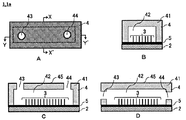
- FIGS. 1A to 1D are diagrams illustrating an example of the device 1 according to the third embodiment.
- FIG. 2 is a diagram for explaining an example of a manufacturing process of the device 1a in which the nanowire 3 is formed on the first surface of the substrate 2, which is an example of the device 1 according to the third embodiment.
- 3A to 3C are views showing various aspects of the cover member 4.
- FIG. 3D shows the substrate 2 having nanowires formed on the first surface.
- FIG. 4 is a diagram for explaining an example of a manufacturing process of the device 1b according to the fourth embodiment.
- FIG. 5 is a flowchart of the first embodiment of the extraction method.
- FIG. 6 is a flowchart of an embodiment of a storage method.
- FIG. 7 is a flowchart of an embodiment of the transfer method.
- FIG. 8A to 8E are photographs substituting for drawings, and are photographs of the devices manufactured in Examples 1 to 5, respectively.
- FIG. 9 is a graph showing the results of measuring the pore size distribution of the films produced in Examples 1, 3 and 4 by the mercury porosimetry method.
- FIG. 9A is a graph showing the distribution when the pore size scale is 1 nm to 100 nm
- FIG. 9B is a graph showing the distribution when the pore size scale is 1 nm to 100 ⁇ m.
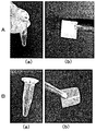
- 10A and 10B are drawing-substituting photographs, (a) a photograph of a centrifuge tube after taking out the device from the centrifuge tube after miRNA extraction, and (b) a photograph of the device taken out from the centrifuge tube.
- FIG. 11A and 11B are drawing-substituting photographs, (a) a photograph of a centrifuge tube immediately after the completion of the miRNA extraction step, (b) a photograph of a centrifuge tube after the device was taken out of the centrifuge tube after miRNA extraction, (c) a centrifuge. It is a photograph of the device taken out from the tube.
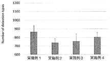
- FIG. 12 is a graph showing the types of miRNA contained in the miRNA extract extracted using the devices of Examples 1 to 4.
- FIG. 13 is a graph showing the analysis results of Examples 5 and 6 and Comparative Example 1.
- 14 is a photograph as a substitute for a drawing, and FIG. 14A is an SEM photograph before dropping saliva in Example 5. Further, FIG. 14B is an SEM photograph after dropping saliva in Example 5.
- the device disclosed in the present application is characterized by including a nanostructure capable of capturing EVs.
- the “nanostructure” means that EVs can be adsorbed by an interaction, and the specific surface area is increased as compared with the minimum area of the same kind and the same amount of material. It means a structure having an improved adsorption efficiency of EVs.
- the nanostructure can be produced, for example, by using a material having fine pores (nanopores) or by aggregating (dense) fine fibers (wires).
- the “nanopore” means a nano-sized opening having an average size of 10 nm or more and less than 1000 nm, or a fiber interval.
- nanopores when described as “with nanopores” or “including nanopores”, it has pores distributed in the nano order (1 nm or more and less than 1000 nm), and the average size of only nano order pores is 10 nm or more and 1000 nm. Means less than. Therefore, as long as the “nanopore” is included, a micro-order (1 ⁇ m or more and less than 1000 ⁇ m) pore may be included, but the micro-order pore is not a basis for calculating the average size of the “nanopore”. Further, when it is described as “without nanopores”, it means that the average size of nanopores is not included or only the nanopores are out of the above average size of “nanopores”.
- the shape of the device including the nanostructure is not particularly limited, and may be, for example, a film shape; a thread (string) shape; a columnar shape, a prismatic shape, or a three-dimensional shape such as an indefinite shape. ..
- a film shape a thread (string) shape
- a columnar shape a prismatic shape
- a three-dimensional shape such as an indefinite shape. ..
- each embodiment of the device using a film-shaped and nanowire will be described, but the device embodiment below is merely an example, and if the definition of the “nanostructure” is satisfied, the device is The present invention is not limited to the embodiments illustrated below.
- the average size of nanopores can be measured by the mercury penetration method.
- the first embodiment of the device uses a film made with cellulose nanofibers as nanostructures.
- wood fibers cellulose fibers
- This cellulose fiber is composed of a bundle of innumerable cellulose nanofibers.
- the cellulose fibers are collided with each other at high pressure in a solvent in the presence of a TEMPO catalyst to release the bundled cellulose fibers, whereby cellulose nanofibers can be obtained.
- the method for producing the cellulose nanofibers described above is merely an example, and other methods may be used.
- the device according to the first embodiment can be produced by suction-filtering the obtained solvent containing cellulose nanofibers so that the cellulose nanofibers aggregate and form a film due to surface tension.
- Water etc. are mentioned as a solvent which disperse
- the films made can be non-woven.
- the cellulose nanofibers of the produced film may have a gap (nanopore).
- the efficiency of capturing EVs can be improved by adjusting the size of the nanopore.
- the average size of the nanopores can be, for example, a lower limit value of 10 nm or more, 15 nm or more, 20 nm or more, 25 nm or more, 30 nm or more, and an upper limit value of less than 1000 nm, 500 nm or less, 200 nm or less, 100 nm or less.
- the EVs be confined in the nanopores, as shown in Examples described later.
- the size of each nanopore has a distribution, even if the average size of the nanopores is 10 nm, there are nanopores of a size capable of confining EVs.
- the lower limit of the average size of the nanopores may be, for example, 40 nm or more, 45 nm or more, 50 nm or more, 60 nm or more.
- the size of the nanopore may be measured by a mercury intrusion method, image processing or the like.
- Nanopores are obtained by adding a liquid having a low surface tension (hereinafter, also referred to as a “low surface tension solvent”) to wet cellulose nanofibers that have been aggregated by suction filtration, and then aspirate the aggregated cellulose nanofibers. It can be formed by replacing the solvent contained in the fiber mass with a low surface tension solvent and drying.
- the size of the nanopore can be adjusted by changing the low surface tension solvent added.
- the surface tension of the low surface tension solvent is not particularly limited as long as it is smaller than the surface tension of water (20 ° C., 72.75 mN / m) and is a range in which nanopores can be produced. For example, the surface tension at 20 ° C.
- the formation and size adjustment of the nanopores described above are merely examples, and the formation and size adjustment of the nanopores may be performed by other methods.
- the width of the cellulose nanofibers may be changed and the size of the nanopores may be adjusted by changing the high-pressure treatment conditions for unraveling the cellulose fibers and changing the cellulose raw material such as the type of pulp, bacteria and squirts.
- the number of captured EVs increases, and many types of miRNA can be analyzed.
- the second embodiment of the device differs from the first embodiment in that a film made of cellulose fibers (pulp) is used as a nanostructure instead of cellulose nanofibers.
- the device according to the second embodiment may be manufactured by the same procedure as in the first embodiment of the device, except that cellulose fibers (pulp) are dispersed in a solvent instead of the cellulose nanofibers.
- the gap between the cellulose fibers and the gap between the cellulose nanofibers existing on the surface of the cellulose fiber can be produced and adjusted in size by the same procedure as in the first embodiment. Since the width of the cellulose nanofiber is about 3 nm to 100 nm, nanopores having the same size as in the first embodiment are formed.
- the width of the cellulose fiber is about 20 ⁇ m to 40 ⁇ m. Therefore, the size of the gap is, unlike the first embodiment, multi-scale in the order of nm to ⁇ m, about 10 nm to 1000 nm, and about 1 ⁇ m to 100 ⁇ m.
- the devices according to the first and second embodiments can be used by cutting the produced film into an appropriate size.
- the cut device is attached to a centrifuge tube used in the miRNA extraction step described later, the EVs in a cough are captured by attaching to a mask, and the EVs in sweat can be captured by attaching to a towel or the like. May be.
- the first and second embodiments of the device are film-shaped, they may have other shapes. For example, in the case of a thread (string) shape, a mold (suction filtration filter) in which a groove is formed in a thread (string) shape at the time of suction filtration may be used.
- a solvent in which cellulose (nano) fibers are dispersed may be injected into a coagulation bath such as acetone for spinning.
- suction filtration may be performed using a mold (suction filtration filter) having a predetermined shape.
- the solvent in which the cellulose (nano) fibers are dispersed is introduced into only a part of the suction filtration filter, and a lump in which the cellulose (nano) fibers are aggregated is produced by suction filtration.
- an amorphous three-dimensional nanostructure By repeating the production of the lump in which the cellulose (nano) fibers are aggregated, an amorphous three-dimensional nanostructure can be produced.
- a three-dimensional nanostructure can also be produced by putting a solvent in which cellulose (nano) fibers are dispersed in a container having a desired shape and subjecting it to freeze-drying.
- the device may be made of only cellulose (nano) fibers, or a filler or the like may be added as long as the object of the present disclosure is not impaired.
- a filler such as polyamidoamine epichlorohydrin as a wet strength agent
- addition of nanowires see the third embodiment described later for nanowires alone, and the like can be mentioned.
- a third embodiment of the device uses nanowires as the device.
- 1A to 1D are diagrams illustrating an example of the device 1 according to the third embodiment.
- 1A is a top view of the device 1a
- FIG. 1B is a sectional view taken along line XX ′ of FIG. 1A
- FIG. 1C is a sectional view taken along line YY ′ of FIG. 1A
- 1D is a cross-sectional view of a modified example of the embodiment shown in FIG. 1C.
- the device 1a includes at least the substrate 2, the nanowires 3, and the cover member 4, and is illustrated in FIGS. 1B to 1D (hereinafter, a description common to FIG. 1 may be simply referred to as “FIG. 1”.
- the device 1a shown in () is the same as the above) includes the catalyst layer 5 for forming the nanowire 3.
- the catalyst layer 5 for forming the nanowires 3 is formed on the substrate 2, and the nanowires 3 are formed on the catalyst layer 5.
- the “first surface” means the outermost surface of the surface of the substrate 2 on which the nanowires 3 are formed. Therefore, as described later, when the “first surface” of the substrate 2 and the “second surface” of the cover member are described as being liquid-tightly adhered, the member of the “first surface” means that the substrate 2 and the catalyst layer 5 or coating layer.
- the nanowire may grow on the “first surface” that is in close contact with the “second surface” of the cover member.
- the flat portion at the root of the nanowire is referred to as the “first surface”.
- the “tip” of the nanowire means an end portion of the nanowire that is farther from the first surface of the substrate 2 among both end portions of the nanowire, and the “front end” of the first surface side of the substrate 2 The end portion of the nanowire is directly referred to as “end portion” in the present specification.
- the cover member 4 includes a cover member base material 41 and a flow path 42 formed in the cover member base material 41.
- the “second surface” is a surface of the cover member base material 41 on the side where the flow path 42 is formed (following the virtual plane when the opening of the flow path 42 is a virtual plane). Means).
- the surface of the cover member base material 41 in contact with the catalyst layer 5 corresponds to the second surface.
- the cover member 4 includes a sample input hole 43 and a sample recovery hole 44. As shown in FIG. 1C, the sample input hole 43 and the sample recovery hole 44 are formed in the cover member substrate 41 so as to penetrate the flow path 42 and the surface 45 opposite to the second surface.
- FIG. 1C shows an example in which the sample liquid is charged and collected from above the device 1 a, but the sample liquid holes 43 and the sample recovery holes 44 are located at the positions of the sample liquid that has been injected to form the nanowires 3.
- the sample solution can be recovered after passing through the above-mentioned region.
- the sample input hole 43 and the sample recovery hole 44 may be formed in the side wall of the flow channel 42.
- FIG. 2 is a diagram for explaining an example of a manufacturing process of a device 1a in which the nanowire 3 is formed on the first surface of the substrate 2, which is an example of the device 1 according to the third embodiment. Note that FIG. 2 shows a cross-sectional view taken along line XX ′ of FIG. 1A.
- the patterning of photolithography may be performed in a pattern in which the nanowire 3 is desired to grow.
- the nanowires 3 may be patterned so that the catalyst layer 5 in the region where the nanowires 3 are formed on the substrate 2 is exposed (see 3a).
- patterning or photolithography may be performed so that the catalyst layers 5 are exposed in dots at predetermined intervals (see 3b).
- the resist 6 in the patterned or drawn portion is developed and removed. (4a, 4b) The resist is removed, and the nanowire 3 is grown from the place where the catalyst layer 5 is exposed. (5a, 5b) By removing the remaining resist, the substrate 2 having the nanowires 3 formed on the catalyst layer 5 formed on the first surface can be manufactured.
- FIGS. 3A to 3C are views showing various aspects of the cover member 4.
- the cover member 4 can be easily manufactured by cutting the second surface 47 of the cover member base material 41 or pressing a convex mold against the material of the cover member base material 41.
- the sample input hole 43 and the sample recovery hole 44 may be formed by using a biopsy trepan, an ultrasonic drill or the like after the transfer.
- the cover member 4 can easily change the cross-sectional area of the flow path 42 as shown in FIGS. 3A and 3B, for example.
- FIG. 3A and 3B are views showing various aspects of the cover member 4.
- a non-planar region 46 for generating turbulent flow in the sample liquid passing therethrough can be formed on any surface of the flow channel 42.
- the non-planar region 46 is not particularly limited as long as turbulent flow can be generated in the sample liquid passing therethrough, and for example, a convex portion or the like may be formed.
- the substrate 2 (FIG. 3D) having the nanowires 3 formed on the first surface, which is manufactured by the process shown in FIG. 2, is covered with the cover member 4 having the flow path 42 having a desired cross-sectional area and shape, thereby forming the device 1a. Can be produced.
- the substrate 2 is not particularly limited as long as the catalyst layer 5 can be laminated.
- silicon, quartz glass, Pyrex (registered trademark) glass, etc. may be mentioned.
- examples of particles for producing the nanowires 3 include ZnO.
- examples of the catalyst for producing the nanowire 3 include gold, platinum, aluminum, copper, iron, cobalt, silver, tin, indium, zinc, gallium, chromium, and oxides thereof.
- the resist 6 for photolithography is not particularly limited as long as it is one generally used in the semiconductor field, such as OFPR8600LB and SU-8.
- the removing liquid for the resist 6 is not particularly limited as long as it is a removing liquid that is commonly used in the semiconductor field, such as dimethylformamide and acetone.
- the nanowire 3 may be grown from the catalyst layer 5 by a known method.
- ZnO fine particles when used as the catalyst layer 5, it can be produced by using a hydrothermal synthesis method.
- the ZnO nanowire 3 can be grown from the portion where the ZnO particles (catalyst layer 5) are exposed by immersing the ZnO nanowire 3.
- the nanowire 3 can be manufactured in the next step.
- a core nanowire is formed by using a material such as 3 , SnO 2 , Sm 2 O 3 , and EuO by a physical vapor deposition method such as pulse laser deposition and a VLS (Vapor-Liquid-Solid) method.
- (B) Using SiO 2 , TiO 2 or the like, a coating layer around the core nanowire by a general vapor deposition method such as sputtering, EB (Electron Beam) vapor deposition, PVD (Physical Vapor Deposition), ALD (Atomic Layer Deposition). To form. Note that the coating layer of (b) above is not essential and may be implemented as needed.
- the diameter of the nanowire 3 may be appropriately adjusted according to the purpose.
- the diameter of the nanowires 3 may be changed by changing the size of the ZnO particles when the ZnO particles are formed.
- the diameter can be appropriately adjusted by changing the vapor deposition time when forming the coating layer.
- the material for producing the cover member 4 is not particularly limited as long as it can cut or transfer a mold.
- thermoplastic resin such as polyethylene, polypropylene, polyvinyl chloride, polyvinylidene chloride, polystyrene, polyvinyl acetate, polytetrafluoroethylene, ABS (acrylonitrile butadiene styrene) resin, AS (acrylonitrile styrene) resin, acrylic resin (PMMA)
- thermosetting resins such as phenol resin, epoxy resin, melamine resin, urea resin, unsaturated polyester resin, alkyd resin, polyurethane, thermosetting polyimide, and silicone rubber.
- FIGS. 1 to 3 are merely examples of the device 1, and there is no particular limitation as long as the nanowire is formed on the substrate 2.
- nanowires may be formed in the channel formed on the substrate 2 by the procedure described in International Publication No. WO 2015/137427.
- the device 1b according to the fourth embodiment is different from the device 1a according to the third embodiment in that the ends of the nanowires 3 are embedded in the first surface of the substrate 2a and the material for forming the substrate 2a is different.
- the other points are the same as those of the device 1a according to the third embodiment.
- FIG. 4 is a diagram for explaining an example of a manufacturing process of the device 1b according to the fourth embodiment.
- the substrate 2 having the nanowires 3 formed on the first surface, which is manufactured by the device 1a according to the third embodiment, is prepared as a template.
- a material for forming the substrate 2a is applied to the mold.
- the substrate 2a is separated from the template to form the substrate 2a in which the nanowires 3 are partially embedded in the first surface.
- the substrate 2a in which the ends of the nanowires 3 are embedded in the first surface is manufactured.
- the growth of the nanowire 3 can be performed by the same procedure as in the first embodiment.
- the device 1b can be manufactured by covering the substrate 2a with the cover member 4 manufactured by the same procedure as in the third embodiment.
- the material forming the substrate 2a is not particularly limited as long as the nanowires 3 can be embedded, and examples thereof include the same material as the cover member 4.
- extraction method a method for capturing EVs using the above device and a method for extracting miRNA after capturing (hereinafter sometimes abbreviated as “extraction method”) will be described.
- the first embodiment of the extraction method includes an extracellular vesicle (EVs) capture step (ST1) and a miRNA extraction step (ST2).
- the extracellular vesicle (EVs) capturing step (ST1) the EVs in the sample solution are captured by the device by bringing the sample solution into contact with the device capable of capturing the EVs.
- the miRNA extraction step (ST2) EVs are crushed by bringing the device capturing EVs into contact with the crushed solution of EVs, and the miRNAs are extracted from EVs into the crushed solution.
- the sample solution is not particularly limited as long as it contains EVs, and biological samples such as blood, lymph, bone marrow fluid, semen, breast milk, amniotic fluid, urine, saliva, nasal fluid, sweat, tears, bile fluid, cerebrospinal fluid, etc.
- biological samples such as blood, lymph, bone marrow fluid, semen, breast milk, amniotic fluid, urine, saliva, nasal fluid, sweat, tears, bile fluid, cerebrospinal fluid, etc.
- a liquid is mentioned.
- the sample solution other than the biological sample solution include a cell culture supernatant, a sample solution for experiments in which EVs is added to a medium or a buffer solution, and the like.
- a biological sample solution is used as the sample solution, a non-invasive sample solution such as urine, saliva, runny nose, sweat, tears and the like is preferable in consideration of reducing the burden on the patient.
- miRNA when miRNA extracted using the device disclosed in the present application was analyzed, many types of miRNA could be analyzed. In other words, using the device disclosed in the present application, it was possible to analyze a trace amount of miRNA that could not be analyzed by the conventional method. Therefore, using the device disclosed in the present application, miRNA can be extracted in a small amount with the same type of sample liquid. Moreover, in order to fractionate and collect EVs by ultracentrifugation, a sample liquid of about several ml is required. However, for example, there are some biological sample solutions such as saliva and tears that make it a great burden on the patient to collect an amount of several ml.
- miRNA can be extracted even with a small amount of the sample liquid, as compared with the conventional method by ultracentrifugation, and thus the saliva in saliva can be extracted. It is particularly useful for extraction of miRNA contained in EVs.
- the EVs disruption solution is not particularly limited as long as EVs can be disrupted, and for example, a commercially available cell lysis buffer (Cell Lysis Buffer) may be used.
- the cell lysis buffer include cell lysis buffer M (Fuji Film Wako Pure Chemical Industries, Ltd., 038-21141), RIPA Buffer (Fuji Film Wako Pure Chemical Industries, Ltd., 182-02451), and the like.
- the time for immersing the device in the disruption solution is not particularly limited as long as EVs can be disrupted and miRNA can be taken out.
- miRNA may be directly captured by the device by flowing a solution obtained by disrupting Evs with a disruption solution into the device.
- the second embodiment of the extraction method includes a device washing step of washing the device capturing EVs between the extracellular vesicle (EVs) capturing step (ST1) and the miRNA extracting step (ST2) shown in FIG.
- the point is different from the first embodiment of the extraction method, and other points are the same as the first embodiment of the extraction method.
- a biological sample solution extracted from a living body such as saliva, sweat, or a runny nose, contains RNase, which is an enzyme that decomposes RNA of foreign substances such as viruses in order to protect the living body from viruses and the like invading from the outside.
- RNase when miRNA is extracted from a biological sample solution containing RNase such as saliva, sweat, or runny nose, RNase may be adsorbed to the device during the extracellular vesicle capturing step. Then, if the miRNA extraction step is performed with a device to which RNase is adsorbed, the miRNA extracted from EVs may be decomposed by RNase.
- the device that captured EVs is cleaned to remove RNase from the device.
- the device capturing the EVs may be immersed in a cleaning liquid for a predetermined time and cleaned.
- the washing time is not particularly limited, but if it is too short, the washing effect is reduced, and if it is too long, the captured EVs are easily peeled off, and the EVs yield may be reduced.
- the device may be immersed in the cleaning liquid for about 1 to 2000 seconds.
- the washing solution include pure water, PBS, NaCl, physiological saline, various buffer solutions such as PBS, and the like. When pure water is used as the cleaning liquid, it is desirable to set the cleaning time shorter than that of the buffer solution or the like so that the captured EVs will not burst due to the osmotic pressure.
- the embodiment of the method for analyzing miRNA includes an analysis step of analyzing miRNA in the disrupted liquid extracted by the first or second embodiment of the extraction method.
- a known miRNA analysis method may be used. For example, (1) total RNA including miRNA is extracted using miRNeasy Mini Kit (QIAGEN), and comprehensive analysis is performed from about 2500 kinds of miRNA using 3D-Gene (registered trademark) miRNA chip, and the chip is analyzed.
- the miRNeasy Serum / Plasma kit (Qiagen) is used to quantify the image, calculate the expression ratio, perform variable gene analysis, and perform cluster analysis, and isolate the total miRNA in the disrupted solution, and then use the miScript II RT Kit (Qiagen).
- the sample solution is dropped on the film or the film is immersed in the sample solution. do it.
- the sample solution is introduced from the sample introduction hole in the extracellular vesicle capturing step (ST1). do it.
- the film may be immersed in the disruption solution in the miRNA extraction step (ST2).
- the miRNA extraction step (ST2) the crushed solution is introduced from the sample introduction hole to extract the extracted miRNA. It is sufficient to collect the crushed liquid containing it.
- the cover member 4 is formed in the devices 1a and 1b according to the third and fourth embodiments, the cover member 4 may not be provided.
- the sample solution in the extracellular vesicle trapping step (ST1), the sample solution may be dropped onto the nanowire, or the device may be immersed so that the nanowire comes into contact with the container containing the sample solution.
- the nanowire portion in the miRNA extraction step (ST2), the nanowire portion may be immersed in the container containing the disrupted solution.
- the nanowires 3 are formed on the first surface of the substrate in the devices 1a and 1b according to the third and fourth embodiments, the nanowires 3 may be used alone.
- the nanowire in the extracellular vesicle capturing step (ST1), the nanowire may be brought into contact with the sample solution by introducing the nanowire into a tube or the like containing the sample solution.
- the miRNA extraction step (ST2) the sample solution may be removed from the tube, and then the disrupted solution may be added to the tube.
- miRNA can be directly extracted from EVs captured in the device.
- the nanowire 3 may be collected from the first surface of the substrate.
- the devices shown in the above embodiments can capture EVs in the sample liquid.
- the device When EVs are crushed with a crushing solution and the extracted miRNA is comprehensively analyzed, if the device is destroyed by the crushing solution, the destroyed residue may adversely affect the analysis process. Therefore, the device should be durable to the disrupted liquid, for example, at least 5 minutes, preferably 30 minutes or more, to the disrupted liquid.
- the film composed of nanowires or cellulose nanofibers is more preferable because it has durability against the crushing liquid.
- the above device is merely an example, and is not limited to the device of the above embodiment as long as it can adsorb EVs (preferably has durability against the crushed liquid).
- a porous material having many small holes on the surface.
- specific examples thereof include microporous materials such as activated carbon and zeolite, mesoporous materials such as silicon dioxide (mesoporous silica) and aluminum oxide, and macroporous materials such as pumice.
- a filter made of molten glass or polymer may be used.
- FIG. 6 is a flowchart of an embodiment of a storage method.
- the embodiment of the storage method includes an extracellular vesicle capturing step (ST11), a drying step (ST12), and a storage step (ST13).
- the extracellular vesicle capturing step (ST11) is performed using a device containing nanopores as a device.
- the extracellular vesicle capturing step (ST11) may be performed using the same procedure and sample solution as the extracellular vesicle capturing step (ST1) of the first embodiment of the extraction method, except that a device containing nanopores is used. Good.
- the drying step (ST12) the liquid of the sample liquid impregnated in the device is removed.
- the amount of sample liquid may be small. Therefore, the drying step may be performed by natural drying in which the liquid is evaporated at room temperature.
- the device that has captured the extracellular vesicles and dried in the drying step (ST12) is stored.
- the difference in storage temperature for example, the extracellular vesicles when stored at refrigeration (4 ° C.) and stored at room temperature.
- room temperature refers to, for example, 10 ° C to 30 ° C, and may be more than 15 ° C and 30 ° C or less.
- FIG. 7 is a flowchart of an embodiment of the transfer method.
- the embodiment of the transfer method includes an extracellular vesicle capturing step (ST21), a drying step (ST22), and a transfer step (ST23).
- the extracellular vesicle capturing step (ST21) and the drying step (ST22) are the same as the extracellular vesicle capturing step (ST11) and the drying step (ST12) of the above-mentioned storage method. Therefore, detailed description is omitted to avoid duplication of description.
- the device that has captured the extracellular vesicles dried in the drying step (ST22) is transferred.
- the temperature during preservation does not significantly affect the accuracy of analysis. Therefore, by contacting a device with a biological sample collected from a patient at a local medical institution, drying it, and then transferring the device to a medical institution having a function of analyzing extracellular vesicles by mail etc.
- a film-like device having nanopores was produced from cellulose nanofibers by the following procedure.
- (2) Hydrophilic polytetrafluoroethylene (PTFE) was prepared from the above nanocellulose aqueous dispersion using a filtration device (KG-90, Advantech Toyo Roshi Kaisha, Ltd.) and a suction device (Aspirator AS-01, AS ONE Corp.).
- Example 1 The device of Example 1 was produced by cutting the produced film into a square having a side of 1 cm.
- FIG. 8A is an SEM photograph of the film produced in Example 1.
- FIG. 9 is a graph showing the results of measuring the pore size distribution of the produced film by the mercury porosimetry method.
- FIG. 9A is a graph showing the distribution when the pore size scale is 1 nm to 100 nm
- FIG. 9B is a graph showing the distribution when the pore size scale is 1 nm to 100 ⁇ m. From FIGS. 9A and 9B, it was confirmed that the film prepared in Example 1 had a distribution of nanopores of about 4 nm to 300 nm and an average size of about 60 nm.
- Example 2 A film-like device was produced from cellulose nanofibers by the same procedure as in Example 1 except that the step of replacing with t BuOH in Example 1 was not performed.
- FIG. 8B is an SEM photograph of the film produced in Example 2. From the photograph, in the device prepared in Example 2, formation of nanopores was not observed between the cellulose nanofibers. Since the nanopores do not exist at all, the size of the nanopores in Example 2 is considered to be 1 nm.
- a film-like device having micro-sized pores was produced from pulp (cellulose fiber) by the following procedure.
- Example 3 was produced by cutting the produced film into a square having a side of 1 cm.
- FIG. 8C is a photograph of the film made in Example 3.
- 9A and 9B show the pore size distribution measured by the mercury porosimetry. As is clear from FIGS. 9A and 9B, the pore size of the produced film was about 7 nm to 100 nm and about 1 ⁇ m to 100 ⁇ m in multiscale.
- Example 4 A film-like device was produced from pulp (cellulose fiber) by the same procedure as in Example 3 except that the substitution step with t BuOH in Example 3 was not performed.
- FIG. 8D is a photograph of the film made in Example 4.
- 9A and 9B show the pore size distribution measured by the mercury porosimetry. As is clear from FIGS. 9A and 9B, the pore size of the produced film was about 1 ⁇ m to 100 ⁇ m.
- a device in which nanowires were embedded in a flow channel formed on a substrate was manufactured by the following procedure.
- a Si (100) substrate (Advantech Co., Ltd.) was subjected to channel patterning of a PDMS-embedded nanowire device.
- a positive resist (OFPR-8600 LB, Tokyo Ohka Kogyo Co. Ltd.) was spin-coated on a Si substrate surface by a spin coater (MS-A100, Mikasa Co., Ltd.) under the conditions of 500 rpm (5 sec) and 3000 rpm (120 sec).
- the resist was fixed on the substrate by evaporating the solvent by heating at 90 ° C. for 12 minutes on a hot plate.
- a glass mask was placed on the heated substrate, and the resist was softened by irradiating with 600 mJ / cm 2 i-line by an exposure machine. Finally, this substrate was immersed in a developing solution (NMD-3, Tokyo Ohka Kogyo Co., Ltd.) for about 10 seconds to peel off the softened resist, and the substrate was taken out from the developing solution and washed with running water. Next, patterning was completed by heating at 90 ° C. for 5 minutes on a hot plate.
- a developing solution NMD-3, Tokyo Ohka Kogyo Co., Ltd.
- a Cr layer to be a seed layer for nanowire growth was formed on the substrate surface.
- the conditions of the sputtering apparatus (EIS-200ERT-YN, Elionix Co., Ltd.) for producing a Cr layer were 1.2 ⁇ 10 ⁇ 2 Pa and 14 min, and a 135 nm Cr layer was deposited.
- This substrate was immersed in 2-propanol warmed to 70 ° C. for 40 minutes on a hot plate, and then ultrasonically treated for 2 minutes by an ultrasonic device to roughly remove the resist outside the channel. After that, the substrate was transferred to 2-propanol at 70 ° C. placed in another container, immersed for 10 minutes, and then subjected to ultrasonic treatment for 1 minute to completely remove the resist outside the channel.
- the fine Cr particles on the substrate were removed by rinsing with 70 ° C. 2-propanol placed in another container.
- the Cr layer was deposited only on the flow path portion on the substrate. This substrate was heated in an electric furnace at 400 ° C. for 2 hours to oxidize the Cr layer and complete the production of the seed layer for nanowire growth.
- HMTA Hexamethylenetetramine
- HMTA Hexamethylenetetramine
- a stirrer for 7 min.
- zinc nitrate hexahydrate 12323, Alfa Aesar
- the mixture was stirred for 7 minutes to prepare a nanowire growth solution.
- the nanowires were grown by immersing in air and heating at 95 ° C. for 3 hours in a constant temperature and high temperature device for blowing air. After that, the substrate was taken out of the beaker and washed with ultrapure water to remove the non-specifically grown nanowires.
- the substrate on which the nanowire produced in (3) above was grown was attached onto a petri dish.
- PDMS prepolymer (Silpot 184, Dow Corning Toray Ind., Ltd.) and curing agent (Silpot 184 CAT, Dow Corning Toray Ind., Ltd.) were placed in the container at a weight ratio of 10: 1.
- the mixture was poured under the conditions of 2000 rpm, 2 min, 2200 rpm, and 6 min. Bubbles in the polymer were removed by vacuuming this for 2 h, and then heating was performed for 2 h on a hot plate at 80 ° C. to promote polymerization and cure the polymer.
- the nanowire on the Si substrate was embedded in PDMS.
- the PDMS in which the nanowires were embedded was peeled off from the Si substrate, and the PDMS-embedded nanowires were attached to a slide glass. Then, the PDMS-embedded nanowire was grown under the same conditions as in (3) above. After the growth, the embedded nanowire was taken out from the beaker, and the nonspecifically grown nanowire was washed away with ultrapure water to remove it, thereby completing the production of the PDMS embedded nanowire.
- FIG. 8E is an enlarged photograph of the nanowire of the device manufactured in Example 5.
- FIG. 10A is a photograph when using the device of Example 1, (a) a photograph of the centrifuge tube after taking out the device from the centrifuge tube after miRNA extraction, and (b) a photograph of the device taken out from the centrifuge tube.
- FIG. 10B is a photograph when the device of Example 2 was used, (a) a photograph of the centrifuge tube after taking out the device from the centrifuge tube after miRNA extraction, and (b) a photograph of the device taken out from the centrifuge tube.
- FIG. 11A is a photograph when using the device of Example 3, (a) a photograph of the centrifuge tube immediately after the completion of the miRNA extraction step, (b) a photograph of the centrifuge tube after the device was taken out of the centrifuge tube after miRNA extraction, (C) A photograph of the device taken out from the centrifuge tube.
- FIG. 11A is a photograph when using the device of Example 3, (a) a photograph of the centrifuge tube immediately after the completion of the miRNA extraction step, (b) a photograph of the centrifuge tube after the device was taken out of the centrifuge tube after miRNA extraction, (C) A photograph of the device taken out from the centrifuge tube.
- 11B is a photograph when the device of Example 4 was used, (a) a photograph of the centrifuge tube immediately after the completion of the miRNA extraction step, (b) a photograph of the centrifuge tube after the device was taken out from the centrifuge tube after miRNA extraction, (C) A photograph of the device taken out from the centrifuge tube.
- FIG. 10A and FIG. 10B when the device made from the cellulose nanofibers of Example 1 and Example 2 was used, even after the EVs were crushed by the crushing liquid, the fiber derived from the device or the like was placed in the centrifuge tube. Was not seen, and the removed device retained its original shape. Therefore, after extracting the miRNA, the miRNA extract could be prepared simply by removing the device with tweezers.
- Example 3 and Example 4 when the device made from the pulp (cellulosic fiber) of Example 3 and Example 4 was used, fibers separated from the device were observed in the centrifuge tube and were taken out. The device was partially defective. Therefore, in Examples 3 and 4, the fibers derived from the device, which interfere as an impurity in the miRNA analysis described later, were removed by centrifugation.
- the type of miRNA contained in the miRNA extract was analyzed using a 3D-Gene (registered trademark) (manufactured by Toray Industries, Inc.) human miRNA chip according to the following procedure.
- A The miRNA extract was purified using a SeraMi Exosome RNA purification column kit (System Biosciences Inc.) according to the instruction manual of the kit manufacturer.
- B 15 ⁇ l of the purified miRNA extract was added to a microarray and 3D-Gene Human miRNA Oligo chip ver. 21 (Toray Industries) was used to analyze miRNA profiling.
- 3D-Gene contains a 2565 human miRNA probe, and the expression of up to 2565 types of miRNA can be analyzed from the miRNA extract.
- C The expression level of each miRNA in the miRNA extract was analyzed by calculating the signal intensity after subtracting the background of all miRNAs in each microarray, and then performing global normalization.
- FIG. 12 is a graph showing the types of miRNA contained in the miRNA extract extracted using the devices of Examples 1 to 4.
- each example is an average value of three analysis results.
- FIG. 12 it was confirmed that miRNA can be directly extracted from the EVs captured in the device when any of the devices of Examples 1 to 4 is used.
- FIGS. 10 and 11 in the devices produced from the pulps of Examples 3 and 4, a part of the device was lost during the crushing of EVs, and fibers separated from the device were observed in the centrifuge tube. Was given. Therefore, it was revealed that the devices of Example 1 and Example 2 are preferable when the miRNA analysis is performed subsequent to the extraction of the miRNA from the sample solution.
- Non-Patent Document 2 in the conventional method for separating EVs by subjecting saliva to ultracentrifugation and analyzing miRNA, in Non-Patent Document 2 described above, there were 27 types as described on page 10. Further, in Non-Patent Document 3 described above, FIG. As described in 7, the number of miRNAs that could be analyzed was 93. In addition, in the method described in Non-Patent Document 3, it is described that saliva of 5 ml or 15 ml is also used, but it is a burden on the subject (patient) to collect such a large amount of saliva. Is very large. On the other hand, when the devices described in Examples 1 to 4 were used, more than 700 types of miRNA were successfully analyzed using only 10 ⁇ l of saliva. In other words, it means that it was possible to analyze even a small amount of miRNA.
- the work of extracting miRNA from EVs in saliva sample liquid is performed.
- the procedure can be simplified.
- miRNA can be directly extracted from a device that captures EVs (and EVs in saliva can be captured in the device at a high rate), so that loss during miRNA extraction work is reduced and highly accurate miRNA analysis can be performed. I confirmed the effect. Therefore, the miRNA extraction method disclosed in the present application is very useful as a sample preparation method in the analysis method of miRNA contained in a sample solution.
- the device described in the first to fourth embodiments can be used for medical examinations and the like. By touching the tongue, it is expected that cancer diagnosis will be performed at the same time.
- Example 2 Urine was used as the sample liquid, the device prepared in Example 5 was used as the device, and miRNA was extracted and analyzed from EVs contained in the urine by the following procedure.
- sample 1 mL of commercially available urine Proteogenex, Bioreclamation IVT, EW Biopharma
- the centrifuge tube was set in a cooling centrifuge at 3000 xg, 15 min, 4 ° C.
- Impurities were precipitated by centrifugation at the conditions.
- the supernatant portion from which the impurities are removed will be referred to as a urine sample.
- miRNA could be directly extracted from EVs captured on the nanowire.
- the analyzed miRNAs were 171, 261, and 352 kinds.
- ExoQuick manufactured by Funakoshi Co., Ltd.
- the types of miRNAs that could be analyzed were 337, 355, and 491.
- Example 6 [Effects of storage temperature and period of device capturing extracellular vesicles on analysis of extracellular vesicles] ⁇ Example 6> Using the device (cellulose nanofiber; with nanopore) produced in Example 1, an experiment was conducted in the following procedure. (1) Preparation of sample liquid Saliva was collected from a subject. Impurities were removed by putting the collected saliva in a centrifuge tube and centrifuging at 3000 g for 15 minutes. (2) Capture of EVs in Sample Saliva sample 10 ⁇ l was dropped on the device and left for about 10 seconds to capture EVs in the saliva sample on the device. (3) Drying of Device The device on which the saliva sample was dropped was dried by leaving it at room temperature for 10 seconds.
- Example 7 An experiment was conducted in the same procedure as in Example 5 except that the storage temperature was 4 ° C.
- FIG. 13 is a graph showing the results of Examples 5 and 6 and Comparative Example 1. As shown in the graph, in comparison with the case of using the device with nanopores (Examples 5 and 6) and the case of using the device without nanopores (Comparative Example 1), the storage stability was observed after the second day. It showed a remarkable effect. In addition, when a device with nanopores is used, the influence of the storage temperature, more specifically, the difference between room temperature (Example 5) and 4 ° C. (Example 6) on the analysis accuracy of extracellular vesicles is particularly large. I could't see it.
- FIG. 14A is a SEM photograph before dropping saliva in Example 5.
- FIG. 14B is an SEM photograph after saliva was dropped and dried in Example 5.
- a large number of nanopores were formed on the surface of the device prepared from the cellulose nanofibers subjected to the step of displacing with a medium having a low surface tension such as t BuOH in Example 1.
- nanopores were closed on the surface of the device after the saliva was dropped and dried. This is probably because the surface tension of saliva, which is a water-based sample, is higher than that of t BuOH, and therefore the force of closing the nanopores acted in the process of drying saliva (the arrow in FIG. 14B partially shows). Exposed EVs are shown.). As shown in FIG. 13, it is considered that the storage stability is increased when the device manufactured in Example 1 is used because EVs are confined between the cellulose nanofiber fibers and the contact with air is reduced. ..
- miRNA can be easily and accurately extracted and analyzed from a sample solution. Therefore, it is useful for cell experiments and the like in medical institutions, universities, companies, research institutions and the like.
Landscapes
- Chemical & Material Sciences (AREA)
- Health & Medical Sciences (AREA)
- Engineering & Computer Science (AREA)
- Life Sciences & Earth Sciences (AREA)
- Biomedical Technology (AREA)
- Genetics & Genomics (AREA)
- Organic Chemistry (AREA)
- Zoology (AREA)
- Bioinformatics & Cheminformatics (AREA)
- Wood Science & Technology (AREA)
- Biochemistry (AREA)
- General Health & Medical Sciences (AREA)
- Biotechnology (AREA)
- General Engineering & Computer Science (AREA)
- Physics & Mathematics (AREA)
- Analytical Chemistry (AREA)
- Microbiology (AREA)
- Crystallography & Structural Chemistry (AREA)
- General Physics & Mathematics (AREA)
- Immunology (AREA)
- Pathology (AREA)
- Plant Pathology (AREA)
- Molecular Biology (AREA)
- Biophysics (AREA)
- Textile Engineering (AREA)
- Sustainable Development (AREA)
- Polymers & Plastics (AREA)
- Medicinal Chemistry (AREA)
- Chemical Kinetics & Catalysis (AREA)
- Clinical Laboratory Science (AREA)
- Apparatus Associated With Microorganisms And Enzymes (AREA)
- Sampling And Sample Adjustment (AREA)
Abstract
The present invention provides a device for efficiently capturing EVs with a simple operation procedure. According to the present invention, provided is, for example, a device that is to be used for capturing extracellular vesicles in a sample solution and that includes a nanostructure for capturing extracellular vesicles.
Description
本出願における開示は、サンプルに含まれる細胞外小胞(Extracellular Vesicles、エクソソーム;以下、「EVs」と記載することがある。)を捕捉するために用いられるデバイス、細胞外小胞の保存方法および移送方法に関する。
The disclosure in the present application discloses a device used for capturing extracellular vesicles (Extracellular Vesicles, exosomes; hereinafter sometimes referred to as “EVs”) contained in a sample, a method for preserving extracellular vesicles, and Regarding transfer method.
EVsは、生体内の細胞から分泌される40nm~1000nm程の大きさを持った膜小胞体であり、血液、尿、唾液、精液などの体液中に存在している。その表面には、分泌細胞由来の膜タンパク質や接着分子、酵素等が存在し、内部にはmRNAやmiRNAといった核酸が含まれている。そのため、他の細胞に伝播し、取り込まれることで受容細胞へ影響を与える。
EVs are membrane vesicles with a size of about 40 nm to 1000 nm that are secreted by cells in the living body and exist in body fluids such as blood, urine, saliva, and semen. Membrane proteins derived from secretory cells, adhesion molecules, enzymes, etc. are present on the surface, and nucleic acids such as mRNA and miRNA are contained inside. Therefore, it propagates to other cells and is taken up to affect the recipient cells.
近年、EVsの生体内での機能の一つとして、がん転移の誘発性があることが明らかとなり、注目を集めている。がん転移とは、がん細胞が、がんの発生部位から血管やリンパを媒介して他の臓器へ伝播し増殖することを言い、がんによる死亡率が高いこともこの転移に起因する。このがん転移の発生に関して、がん原発巣のがん細胞由来のEVsが、血管を通って他の臓器へ伝播し、がん転移性ニッチを形成することや、がん細胞由来のEVsが、正常細胞の異常な増殖を誘発し、がん腫瘍形成へと発展させることなど、EVsとがん転移に関する研究が報告されている(非特許文献1参照)。
Recently, it has become clear that one of the functions of EVs in vivo is the induction of cancer metastasis, and it has been attracting attention. Cancer metastasis means that cancer cells propagate from the cancer site to other organs via blood vessels or lymph and propagate, and the high mortality rate from cancer is also caused by this metastasis. .. With regard to the occurrence of this cancer metastasis, EVs derived from cancer cells of the primary tumor spread to other organs through blood vessels to form a cancer metastatic niche, and EVs derived from cancer cells A study on EVs and cancer metastasis, such as inducing abnormal proliferation of normal cells and developing cancerous tumors, has been reported (see Non-Patent Document 1).
また、EVs中の含まれるmiRNAが、疾患に対するバイオマーカーとして用いられることも知られている(非特許文献2および3参照)。
It is also known that miRNA contained in EVs is used as a biomarker for disease (see Non-Patent Documents 2 and 3).
上記非特許文献2および3に記載されているとおり、サンプル中(非特許文献2および3では唾液)のEVsに含まれるmiRNAを、疾患に対するバイオマーカーとして用いることは知られている。ところで、非特許文献2および3には、サンプル液を超遠心分離することで、サンプル液中からEVsを回収することが記載されている。しかしながら、超遠心による分離は、超遠心後にEVsを含む画分を回収する必要がある。
As described in Non-Patent Documents 2 and 3 above, it is known to use miRNA contained in EVs in a sample (saliva in Non-Patent Documents 2 and 3) as a biomarker for a disease. By the way, Non-Patent Documents 2 and 3 describe that EVs is recovered from the sample liquid by ultracentrifuging the sample liquid. However, separation by ultracentrifugation requires the collection of fractions containing EVs after ultracentrifugation.
そのため、超遠心分離工程が必須となり、作業手順が増えるという問題がある。更に、サンプル液の量が少ない場合、サンプル液中に含まれる微量のmiRNAまで解析するためには、サンプル液中に含まれるEVsを回収する際に、ロスを少なくする必要がある。しかしながら、超遠心分離によりEVsを回収する方法では、EVsを含む画分を採取する操作過程で、サンプル中に含まれるEVsの一部を捨ててしまう恐れがあるという問題がある。また、サンプル液中のEVsの分離方法としては、超遠心法以外にも、市販のキットを用いた、凝集試薬法も知られている。しかしながら、凝集試薬法に関しても、サンプル液中のEVsを凝集した後は、遠心分離等により凝集したEVsを分離する必要があり、作業手順が増えるとともに、EVsの分離作業中にロスが生じるという問題がある。したがって、サンプル液から、作業手順が簡単で且つ効率的にサンプル液中のEVsを捕捉するために用いられるデバイス(以下、単に「デバイス」と記載することがある。)が求められる。
Therefore, there is a problem that the ultracentrifugation process becomes essential and the work procedure increases. Furthermore, when the amount of the sample solution is small, it is necessary to reduce loss when collecting EVs contained in the sample solution in order to analyze even a very small amount of miRNA contained in the sample solution. However, the method of recovering EVs by ultracentrifugation has a problem that a part of EVs contained in a sample may be discarded in the process of collecting a fraction containing EVs. In addition to the ultracentrifugation method, an agglutination reagent method using a commercially available kit is also known as a method for separating EVs from a sample solution. However, also in the agglutination reagent method, after the EVs in the sample liquid are agglutinated, it is necessary to separate the agglomerated EVs by centrifugation or the like, which increases the work procedure and causes a loss during the EVs separation operation. There is. Therefore, a device (hereinafter, sometimes simply referred to as “device”) used for capturing EVs in a sample liquid with a simple and efficient procedure from the sample liquid is required.
本出願における開示は、上記問題点を解決するためになされたものであり、鋭意研究を行ったところ、[1]EVsを捕捉できるナノ構造体を含むデバイスを用い、デバイスとサンプル液を接触させることで、EVsをデバイスに捕捉でき、[2]EVsを捕捉したデバイスを直接EVsの破砕液と接触させることで、[3]デバイスで捕捉したEVsを分離する工程を要せず、デバイスに捕捉したEVsから直接miRNAを抽出できること、を新たに見出した。また、任意付加的に、セルロースファイバーまたはセルロースナノファイバーを用いて作製したナノポアを含むデバイスを用いると、サンプル液から捕捉したEVsの保存安定性が高くなり、EVsの移送の利便性が高くなることを、新たに見出した。
The disclosure in the present application was made in order to solve the above problems, and as a result of intensive research, [1] a device including a nanostructure capable of capturing EVs was used to bring the device into contact with a sample solution. Therefore, EVs can be captured in the device, and [2] EVs captured in the device can be directly contacted with the crushed solution of EVs, and the EVs captured in [3] the device can be captured without the step of separating the EVs. It was newly found that miRNA can be directly extracted from the obtained EVs. In addition, if a device containing nanopores produced by using cellulose fibers or cellulose nanofibers is optionally used, the storage stability of EVs captured from a sample solution is increased and the convenience of EVs transfer is increased. Was newly found.
すなわち、本出願における開示の目的は、作業手順が簡単で且つ効率的にEVsを捕捉できるデバイスを提供することである。また、任意付加的に、EVsの保存方法および移送方法を提供することである。
That is, an object of the disclosure in the present application is to provide a device that can easily and efficiently capture EVs in a work procedure. It is also optionally to provide a method of storing and transferring EVs.
本出願における開示は、以下に示す、デバイス、保存方法、および、移送方法に関する。
The disclosure in the present application relates to a device, a storage method, and a transfer method described below.
(1)サンプル液中の細胞外小胞を捕捉するために用いられるデバイスであって、該デバイスは、
細胞外小胞を捕捉できるナノ構造体を含む、
デバイス。
(2)前記ナノ構造体が、
ナノワイヤ、
セルロースファイバーを用いて作製した構造体、および、
セルロースナノファイバーを用いて作製した構造体、
から選択される何れか一つを含む、
上記(1)に記載のデバイス。
(3)前記ナノ構造体が、セルロースナノファイバーを用いて作製した構造体である、
上記(2)に記載のデバイス。
(4)前記ナノ構造体のセルロースナノファイバー同士の隙間が、1nm以上、1000nm未満である、
上記(3)に記載のデバイス。
(5)前記ナノ構造体が、
セルロースファイバーを用いて作製した、平均サイズが10nm以上、1000nm未満のナノポアを含む構造体、および、
セルロースナノファイバーを用いて作製した、平均サイズが10nm以上、1000nm未満のナノポアを含む構造体、
から選択される何れか一つを含む、
上記(2)に記載のデバイス。
(6)前記サンプル液が、非侵襲性の生体サンプル液である、
上記(1)~(5)の何れか一つに記載のデバイス。
(7)前記生体サンプル液が唾液である、
上記(6)に記載のデバイス。
(8)細胞外小胞の保存方法であって、該保存方法は、
上記(5)に記載のデバイスとサンプル液を接触させることで、サンプル液中の細胞外小胞をデバイスに捕捉する細胞外小胞捕捉工程と、
デバイスに含侵したサンプル液の液体を除去する乾燥工程と、
乾燥工程で乾燥した、細胞外小胞を捕捉したデバイスを保存する保存工程と、
を含む、保存方法。
(9)前記保存工程が、室温で実施される、
上記(8)に記載の保存方法。
(10)細胞外小胞の移送方法であって、該移送方法は、
上記(5)に記載のデバイスとサンプル液を接触させることで、サンプル液中の細胞外小胞をデバイスに捕捉する細胞外小胞捕捉工程と、
デバイスに含侵したサンプル液の液体を除去する乾燥工程と、
乾燥工程で乾燥した、細胞外小胞を捕捉したデバイスを移送する移送工程と、
を含む、移送方法。
(11)前記移送工程が、室温で実施される、
上記(10)に記載の移送方法。
(12)細胞外小胞を捕捉できるナノ構造体が、セルロースファイバーを含む不織布である、上記(1)に記載のデバイス。
(13)セルロースファイバーが、セルロースナノファイバーである、上記(12)に記載のデバイス。 (1) A device used for capturing extracellular vesicles in a sample solution, the device comprising:
Includes nanostructures that can trap extracellular vesicles,
device.
(2) The nanostructure is
Nanowires,
A structure produced using cellulose fiber, and
Structure made using cellulose nanofibers,
Including any one selected from
The device according to (1) above.
(3) The nanostructure is a structure produced using cellulose nanofibers,
The device according to (2) above.
(4) The gap between the cellulose nanofibers of the nanostructure is 1 nm or more and less than 1000 nm,
The device according to (3) above.
(5) The nanostructure is
A structure including nanopores having an average size of 10 nm or more and less than 1000 nm, which is produced by using a cellulose fiber, and
A structure including nanopores having an average size of 10 nm or more and less than 1000 nm, which is produced using cellulose nanofibers.
Including any one selected from
The device according to (2) above.
(6) The sample liquid is a non-invasive biological sample liquid,
The device according to any one of (1) to (5) above.
(7) The biological sample liquid is saliva,
The device according to (6) above.
(8) A method for preserving extracellular vesicles, which comprises:
An extracellular vesicle capturing step of capturing the extracellular vesicles in the sample solution on the device by bringing the device into contact with the sample solution according to (5) above;
A drying step of removing the liquid of the sample liquid impregnated in the device,
A storage step of storing the device that has captured the extracellular vesicles dried in the drying step,
Saving method including.
(9) The storage step is performed at room temperature,
The storage method according to (8) above.
(10) A method for transferring extracellular vesicles, which comprises:
An extracellular vesicle capturing step of capturing the extracellular vesicles in the sample solution on the device by bringing the device into contact with the sample solution according to (5) above;
A drying step of removing the liquid of the sample liquid impregnated in the device,
A transfer step of transferring the device that has captured the extracellular vesicles dried in the drying step,
And a transfer method including.
(11) The transfer step is performed at room temperature,
The transfer method according to (10) above.
(12) The device according to (1) above, wherein the nanostructure capable of capturing extracellular vesicles is a nonwoven fabric containing cellulose fibers.
(13) The device according to (12) above, wherein the cellulose fiber is a cellulose nanofiber.
本出願で開示するデバイスにより、サンプル液中のEVsを捕捉し、その後、デバイスに捕捉したEVsから直接miRNAを抽出できる。また、任意付加的な効果として、セルロースファイバーまたはセルロースナノファイバーを用いて作製したナノポアを含むデバイスを用いると、EVsの保存安定性が高くなり、EVsの移送の利便性が高くなる。
With the device disclosed in the present application, it is possible to capture EVs in a sample solution and then directly extract miRNA from the EVs captured in the device. Further, as an optional additional effect, the use of a device containing nanopores produced by using cellulose fibers or cellulose nanofibers increases the storage stability of EVs and enhances the convenience of EVs transfer.
以下、図面を参照しつつ、デバイスについて、詳しく説明する。なお、本明細書において、同種の機能を有する部材には、同一または類似の符号が付されている。そして、同一または類似の符号の付された部材について、繰り返しとなる説明が省略される場合がある。
The device will be described in detail below with reference to the drawings. In this specification, members having the same type of function are designated by the same or similar reference numerals. Then, repeated description may be omitted for members having the same or similar reference numerals.
本出願で開示するデバイスは、EVsを捕捉できるナノ構造体を含むことが特徴である。なお、本明細書において「ナノ構造体」とは、相互作用によりEVsを吸着することができ、且つ、同種で同量の材料の最小となる面積と比較して、比表面積を大きくすることでEVsの吸着効率を高めた構造体を意味する。ナノ構造体は、例えば、微細な孔(ナノポア)を有する材料を用いる、または、微細な繊維(ワイヤ)を凝集(密集)させる等により作製することができる。なお、本明細書において「ナノポア」とは、平均サイズが10nm以上で、1000nm未満のナノサイズの開口部、または、繊維間隔を意味する。また、「ナノポアあり」または「ナノポアを含む」と記載した場合は、ナノオーダー(1nm以上、1000nm未満)で分布するポアを有し、且つ、ナノオーダーのポアのみの平均サイズが10nm以上、1000nm未満であることを意味する。したがって、「ナノポア」を含んでいれば、マイクロオーダー(1μm以上、1000μm未満)のポアを含んでもよいが、マイクロオーダーのポアは、「ナノポア」の平均サイズの算出根拠とはならない。また、「ナノポアなし」と記載した場合は、ナノオーダーのポアを含まない、または、ナノオーダーのポアのみの平均サイズが、上記「ナノポア」の平均サイズから外れていることを意味する。また、ナノ構造体を含むデバイスの形状に特に制限はなく、例えば、フィルム状;糸(紐)状;円柱状、角柱状、或いは、不定形状等の立体形状;等の何れであってもよい。以下に、フィルム状およびナノワイヤを用いたデバイスの各実施形態を説明するが、以下のデバイスの実施形態は単なる例示であって、前記「ナノ構造体」の定義を満たすものであれば、デバイスは以下に例示する実施形態に限定されない。ナノポアの平均サイズは、水銀圧入法で測定することができる。
The device disclosed in the present application is characterized by including a nanostructure capable of capturing EVs. In the present specification, the “nanostructure” means that EVs can be adsorbed by an interaction, and the specific surface area is increased as compared with the minimum area of the same kind and the same amount of material. It means a structure having an improved adsorption efficiency of EVs. The nanostructure can be produced, for example, by using a material having fine pores (nanopores) or by aggregating (dense) fine fibers (wires). In the present specification, the “nanopore” means a nano-sized opening having an average size of 10 nm or more and less than 1000 nm, or a fiber interval. Further, when described as “with nanopores” or “including nanopores”, it has pores distributed in the nano order (1 nm or more and less than 1000 nm), and the average size of only nano order pores is 10 nm or more and 1000 nm. Means less than. Therefore, as long as the “nanopore” is included, a micro-order (1 μm or more and less than 1000 μm) pore may be included, but the micro-order pore is not a basis for calculating the average size of the “nanopore”. Further, when it is described as “without nanopores”, it means that the average size of nanopores is not included or only the nanopores are out of the above average size of “nanopores”. The shape of the device including the nanostructure is not particularly limited, and may be, for example, a film shape; a thread (string) shape; a columnar shape, a prismatic shape, or a three-dimensional shape such as an indefinite shape. .. Hereinafter, each embodiment of the device using a film-shaped and nanowire will be described, but the device embodiment below is merely an example, and if the definition of the “nanostructure” is satisfied, the device is The present invention is not limited to the embodiments illustrated below. The average size of nanopores can be measured by the mercury penetration method.
(デバイスの第1の実施形態)
デバイスの第1の実施形態は、セルロースナノファイバーを用いて作製したフィルムをナノ構造体として用いる。セルロースナノファイバーを得るためには、先ず、木材チップから木材繊維(セルロースファイバー)を取り出してパルプ化する。このセルロースファイバーは、無数のセルロースナノファイバーが束になって構成されている。次に、このセルロースファイバーを、TEMPO触媒の存在下で、溶媒中で高圧で繊維同士を衝突させ、束になっているセルロースファイバーを解すことでセルロースナノファイバーを得ることができる。なお、前記のセルロースナノファイバーの作製方法は単なる例示で、その他の方法であってもよい。第1の実施形態に係るデバイスは、得られたセルロースナノファイバーを含む溶媒を吸引濾過することで、セルロースナノファイバー同士が表面張力により凝集・フィルム化することで作製できる。セルロースナノファイバーを分散する溶媒としては、水等が挙げられる。ある態様では、作製したフィルムは不織布であり得る。 (First Embodiment of Device)
The first embodiment of the device uses a film made with cellulose nanofibers as nanostructures. In order to obtain cellulose nanofibers, first, wood fibers (cellulose fibers) are taken out from wood chips and pulped. This cellulose fiber is composed of a bundle of innumerable cellulose nanofibers. Then, the cellulose fibers are collided with each other at high pressure in a solvent in the presence of a TEMPO catalyst to release the bundled cellulose fibers, whereby cellulose nanofibers can be obtained. The method for producing the cellulose nanofibers described above is merely an example, and other methods may be used. The device according to the first embodiment can be produced by suction-filtering the obtained solvent containing cellulose nanofibers so that the cellulose nanofibers aggregate and form a film due to surface tension. Water etc. are mentioned as a solvent which disperse | distributes a cellulose nanofiber. In some embodiments, the films made can be non-woven.
なお、第1の実施形態に係るデバイスは、作製したフィルムのセルロースナノファイバー同士が隙間(ナノポア)を有するようにしてもよい。ナノポアのサイズを調整することで、EVsの捕捉効率を向上することができる。ナノポアの平均サイズは、例えば、下限値を10nm以上、15nm以上、20nm以上、25nm以上、30nm以上とし、上限値を1000nm未満、500nm以下、200nm以下、100nm以下とすることができる。なお、第1の実施形態に係るデバイスをEVsの保存方法、または、移送方法に用いる場合、後述する実施例に示すとおり、ナノポア内にEVsが閉じ込められることが好ましい。各々のナノポアのサイズには分布があるので、ナノポアの平均サイズが10nmの場合であっても、EVsを閉じ込められるサイズのナノポアは存在する。しかしながら、より多くのEVsをナノポアの中に閉じ込めるため、ナノポアの平均サイズの下限を、例えば、40nm以上、45nm以上、50nm以上、60nm以上等にしてもよい。ナノポアのサイズは、水銀圧入法、画像処理等により測定すればよい。
In the device according to the first embodiment, the cellulose nanofibers of the produced film may have a gap (nanopore). The efficiency of capturing EVs can be improved by adjusting the size of the nanopore. The average size of the nanopores can be, for example, a lower limit value of 10 nm or more, 15 nm or more, 20 nm or more, 25 nm or more, 30 nm or more, and an upper limit value of less than 1000 nm, 500 nm or less, 200 nm or less, 100 nm or less. When the device according to the first embodiment is used for a method of storing or transferring EVs, it is preferable that the EVs be confined in the nanopores, as shown in Examples described later. Since the size of each nanopore has a distribution, even if the average size of the nanopores is 10 nm, there are nanopores of a size capable of confining EVs. However, in order to confine more EVs in the nanopores, the lower limit of the average size of the nanopores may be, for example, 40 nm or more, 45 nm or more, 50 nm or more, 60 nm or more. The size of the nanopore may be measured by a mercury intrusion method, image processing or the like.
ナノポアは、吸引濾過して凝集した湿潤状態のセルロースナノファイバーに、表面張力の低い液体(以下、「低表面張力溶媒」と記載することがある。)を加えて引き続き吸引し、凝集したセルロースナノファイバーの塊に含まれる溶媒を、低表面張力溶媒で置換・乾燥することで形成できる。ナノポアのサイズは、加える低表面張力溶媒を変えることで調整できる。低表面張力溶媒の表面張力は、水の表面張力(20℃、72.75mN/m)より小さく、且つ、ナノポアが作製できる範囲であれば特に制限はない。例えば20℃における表面張力が、35mN/m以下、30mN/m以下、25mN/m以下、20mN/m以下、等とすることができる。低表面張力溶媒の具体例としては、ターシャリーブチルアルコール(20.7mN/m)、エタノール(22.55mN/m)、イソプロパノール(20.8mN/m)等が挙げられる。なお、上記のナノポアの形成およびサイズの調整は、単なる例示であって、その他の方法でナノポアの形成およびサイズの調整を行ってもよい。例えば、セルロースファイバーを解す高圧処理条件や、パルプの種類・バクテリア・ホヤといったセルロース原料を変えることでセルロースナノファイバーの幅を変え、ナノポアのサイズを調整してもよい。ナノポアを設けた場合、捕捉するEVsが増え、多くの種類のmiRNAの解析ができる。
Nanopores are obtained by adding a liquid having a low surface tension (hereinafter, also referred to as a “low surface tension solvent”) to wet cellulose nanofibers that have been aggregated by suction filtration, and then aspirate the aggregated cellulose nanofibers. It can be formed by replacing the solvent contained in the fiber mass with a low surface tension solvent and drying. The size of the nanopore can be adjusted by changing the low surface tension solvent added. The surface tension of the low surface tension solvent is not particularly limited as long as it is smaller than the surface tension of water (20 ° C., 72.75 mN / m) and is a range in which nanopores can be produced. For example, the surface tension at 20 ° C. can be 35 mN / m or less, 30 mN / m or less, 25 mN / m or less, 20 mN / m or less, and the like. Specific examples of the low surface tension solvent include tertiary butyl alcohol (20.7 mN / m), ethanol (22.55 mN / m), isopropanol (20.8 mN / m) and the like. The formation and size adjustment of the nanopores described above are merely examples, and the formation and size adjustment of the nanopores may be performed by other methods. For example, the width of the cellulose nanofibers may be changed and the size of the nanopores may be adjusted by changing the high-pressure treatment conditions for unraveling the cellulose fibers and changing the cellulose raw material such as the type of pulp, bacteria and squirts. When nanopores are provided, the number of captured EVs increases, and many types of miRNA can be analyzed.
(デバイスの第2の実施形態)
デバイスの第2の実施形態は、セルロースナノファイバーに代え、セルロースファイバー(パルプ)を用いて作製したフィルムをナノ構造体として用いている点で、第1の実施形態と異なる。第2の実施形態に係るデバイスは、セルロースナノファイバーに代え、セルロースファイバー(パルプ)を溶媒に分散する以外は、デバイスの第1の実施形態と同様の手順で作製すればよい。セルロースファイバー同士の隙間、および、セルロースファイバー表面に存在するセルロースナノファイバー同士の隙間も、第1の実施形態と同様の手順で作製およびサイズの調整ができる。なお、セルロースナノファイバーの幅は約3nm~100nmであることから、第1の実施形態と同様のサイズのナノポアが形成される。一方、セルロースファイバーの幅は約20μm~40μmである。したがって、隙間のサイズは、第1の実施形態と異なり、nm~μmオーダーで、約10nm~1000nm、および、約1μm~100μmのマルチスケールである。 (Second Embodiment of Device)
The second embodiment of the device differs from the first embodiment in that a film made of cellulose fibers (pulp) is used as a nanostructure instead of cellulose nanofibers. The device according to the second embodiment may be manufactured by the same procedure as in the first embodiment of the device, except that cellulose fibers (pulp) are dispersed in a solvent instead of the cellulose nanofibers. The gap between the cellulose fibers and the gap between the cellulose nanofibers existing on the surface of the cellulose fiber can be produced and adjusted in size by the same procedure as in the first embodiment. Since the width of the cellulose nanofiber is about 3 nm to 100 nm, nanopores having the same size as in the first embodiment are formed. On the other hand, the width of the cellulose fiber is about 20 μm to 40 μm. Therefore, the size of the gap is, unlike the first embodiment, multi-scale in the order of nm to μm, about 10 nm to 1000 nm, and about 1 μm to 100 μm.
第1および第2の実施形態に係るデバイスは、作製したフィルムを適当なサイズに切断してそのまま用いることができる。或いは、後述するmiRNA抽出工程の際に用いる遠沈管等に切断したデバイスを貼り付ける、マスクに貼り付けることで咳中のEVsを捕捉する、タオル等に貼り付け汗中のEVsを捕捉できるようにしてもよい。また、デバイスの第1および第2の実施形態はフィルム状であるが、その他の形状であってもよい。例えば、糸(紐)状にする場合は、吸引濾過する際に糸(紐)状に溝が形成されている型(吸引濾過フィルター)を用いればよい。また、セルロース(ナノ)ファイバーが分散した溶媒をアセトン等の凝固浴に射出して紡糸してもよい。所定の立体形状にする場合は、所定の形状が形成されている型(吸引濾過フィルター)を用いて吸引濾過すればよい。また、不定形の立体形状にする場合は、先ず、吸引濾過フィルターの一部のみにセルロース(ナノ)ファイバーが分散した溶媒を投入し、吸引濾過によりセルロース(ナノ)ファイバーが凝集した塊を作製し、前記セルロース(ナノ)ファイバーが凝集した塊の作製を繰り返すことで、不定形の立体形状のナノ構造体を作製することができる。また、セルロース(ナノ)ファイバーが分散した溶媒を所望の形状の容器に入れ、凍結乾燥処理することによっても立体形状のナノ構造体を作製することができる。また、デバイスは、セルロース(ナノ)ファイバーのみで作製してもよいし、本開示の目的を損なわない範囲内であれば充填剤等を添加してもよい。例えば、湿潤紙力増強剤としてのポリアミドアミンエピクロロヒドリンといった充填剤の添加、ナノワイヤ(ナノワイヤは後述する第3の実施形態を参照)を単体で添加、等が挙げられる。
The devices according to the first and second embodiments can be used by cutting the produced film into an appropriate size. Alternatively, the cut device is attached to a centrifuge tube used in the miRNA extraction step described later, the EVs in a cough are captured by attaching to a mask, and the EVs in sweat can be captured by attaching to a towel or the like. May be. Also, although the first and second embodiments of the device are film-shaped, they may have other shapes. For example, in the case of a thread (string) shape, a mold (suction filtration filter) in which a groove is formed in a thread (string) shape at the time of suction filtration may be used. Alternatively, a solvent in which cellulose (nano) fibers are dispersed may be injected into a coagulation bath such as acetone for spinning. In the case of forming a predetermined three-dimensional shape, suction filtration may be performed using a mold (suction filtration filter) having a predetermined shape. Also, in the case of making an irregular three-dimensional shape, first, the solvent in which the cellulose (nano) fibers are dispersed is introduced into only a part of the suction filtration filter, and a lump in which the cellulose (nano) fibers are aggregated is produced by suction filtration. By repeating the production of the lump in which the cellulose (nano) fibers are aggregated, an amorphous three-dimensional nanostructure can be produced. A three-dimensional nanostructure can also be produced by putting a solvent in which cellulose (nano) fibers are dispersed in a container having a desired shape and subjecting it to freeze-drying. In addition, the device may be made of only cellulose (nano) fibers, or a filler or the like may be added as long as the object of the present disclosure is not impaired. For example, addition of a filler such as polyamidoamine epichlorohydrin as a wet strength agent, addition of nanowires (see the third embodiment described later for nanowires) alone, and the like can be mentioned.
(デバイスの第3の実施形態)
デバイスの第3の実施形態は、ナノワイヤをデバイスとして用いている。図1A乃至図1Dは、第3の実施形態に係るデバイス1の一例を示す図である。図1Aはデバイス1aの上面図、図1Bは図1AのX-X’断面図、図1Cは図1AのY-Y’断面である。また、図1Dは図1Cに示す実施形態の変形例の断面図である。デバイス1aは、基板2、ナノワイヤ3、カバー部材4を少なくとも含み、図1B~図1D(以下、図1に共通する説明は、単に「図1」と記載することがある。以下の段落においても同様である。)に示すデバイス1aでは、ナノワイヤ3を形成するための触媒層5を含んでいる。デバイス1aは、基板2上にナノワイヤ3を形成するための触媒層5が形成され、触媒層5の上にナノワイヤ3が形成されている。なお、本明細書において「第1面」とは、基板2のナノワイヤ3が形成されている側の面の最表面を意味する。したがって、後述するとおり、基板2の「第1面」とカバー部材の「第2面」が液密に密着と記載した場合、「第1面」の部材は、製法により、基板2、触媒層5または被覆層になる。さらに、カバー部材の「第2面」と密着する「第1面」にナノワイヤが成長している場合もあるが、その場合はナノワイヤの根元にある平坦部を「第1面」とする。また、本明細書においてナノワイヤの「先端」とは、ナノワイヤの両方の端部の内、基板2の第1面から離れた方のナノワイヤの端部を意味し、基板2の第1面側のナノワイヤの端部は、本明細書ではそのまま「端部」と記載する。 (Third Embodiment of Device)
A third embodiment of the device uses nanowires as the device. 1A to 1D are diagrams illustrating an example of thedevice 1 according to the third embodiment. 1A is a top view of the device 1a, FIG. 1B is a sectional view taken along line XX ′ of FIG. 1A, and FIG. 1C is a sectional view taken along line YY ′ of FIG. 1A. 1D is a cross-sectional view of a modified example of the embodiment shown in FIG. 1C. The device 1a includes at least the substrate 2, the nanowires 3, and the cover member 4, and is illustrated in FIGS. 1B to 1D (hereinafter, a description common to FIG. 1 may be simply referred to as “FIG. 1”. Also in the following paragraphs. The device 1a shown in () is the same as the above) includes the catalyst layer 5 for forming the nanowire 3. In the device 1 a, the catalyst layer 5 for forming the nanowires 3 is formed on the substrate 2, and the nanowires 3 are formed on the catalyst layer 5. In the present specification, the “first surface” means the outermost surface of the surface of the substrate 2 on which the nanowires 3 are formed. Therefore, as described later, when the “first surface” of the substrate 2 and the “second surface” of the cover member are described as being liquid-tightly adhered, the member of the “first surface” means that the substrate 2 and the catalyst layer 5 or coating layer. Furthermore, the nanowire may grow on the “first surface” that is in close contact with the “second surface” of the cover member. In that case, the flat portion at the root of the nanowire is referred to as the “first surface”. Further, in the present specification, the “tip” of the nanowire means an end portion of the nanowire that is farther from the first surface of the substrate 2 among both end portions of the nanowire, and the “front end” of the first surface side of the substrate 2 The end portion of the nanowire is directly referred to as “end portion” in the present specification.
デバイスの第3の実施形態は、ナノワイヤをデバイスとして用いている。図1A乃至図1Dは、第3の実施形態に係るデバイス1の一例を示す図である。図1Aはデバイス1aの上面図、図1Bは図1AのX-X’断面図、図1Cは図1AのY-Y’断面である。また、図1Dは図1Cに示す実施形態の変形例の断面図である。デバイス1aは、基板2、ナノワイヤ3、カバー部材4を少なくとも含み、図1B~図1D(以下、図1に共通する説明は、単に「図1」と記載することがある。以下の段落においても同様である。)に示すデバイス1aでは、ナノワイヤ3を形成するための触媒層5を含んでいる。デバイス1aは、基板2上にナノワイヤ3を形成するための触媒層5が形成され、触媒層5の上にナノワイヤ3が形成されている。なお、本明細書において「第1面」とは、基板2のナノワイヤ3が形成されている側の面の最表面を意味する。したがって、後述するとおり、基板2の「第1面」とカバー部材の「第2面」が液密に密着と記載した場合、「第1面」の部材は、製法により、基板2、触媒層5または被覆層になる。さらに、カバー部材の「第2面」と密着する「第1面」にナノワイヤが成長している場合もあるが、その場合はナノワイヤの根元にある平坦部を「第1面」とする。また、本明細書においてナノワイヤの「先端」とは、ナノワイヤの両方の端部の内、基板2の第1面から離れた方のナノワイヤの端部を意味し、基板2の第1面側のナノワイヤの端部は、本明細書ではそのまま「端部」と記載する。 (Third Embodiment of Device)
A third embodiment of the device uses nanowires as the device. 1A to 1D are diagrams illustrating an example of the
カバー部材4は、カバー部材用基材41、カバー部材用基材41に形成された流路42を含む。なお、本明細書において「第2面」とは、カバー部材用基材41の流路42が形成される側の面(流路42の開口部分を仮想平面とした場合、該仮想平面に続く面)を意味する。図1Bに示す例では、カバー部材用基材41の触媒層5と接している面が第2面に相当する。また、図1Cに示す例では、カバー部材4は、サンプル投入孔43およびサンプル回収孔44を含んでいる。サンプル投入孔43およびサンプル回収孔44は、図1Cに示すように、流路42と第2面とは反対側の面45を貫通するようにカバー部材用基板41に形成されている。なお、図1Cに示す例は、サンプル液をデバイス1aの上方から投入および回収する例を示しているが、サンプル投入孔43およびサンプル回収孔44の位置は、投入したサンプル液がナノワイヤ3を形成した領域を通過し、通過後にサンプル液を回収できれば特に制限はない。例えば、図1Dに示すように、流路42の側壁にサンプル投入孔43およびサンプル回収孔44を形成してもよい。
The cover member 4 includes a cover member base material 41 and a flow path 42 formed in the cover member base material 41. In the present specification, the “second surface” is a surface of the cover member base material 41 on the side where the flow path 42 is formed (following the virtual plane when the opening of the flow path 42 is a virtual plane). Means). In the example shown in FIG. 1B, the surface of the cover member base material 41 in contact with the catalyst layer 5 corresponds to the second surface. Further, in the example shown in FIG. 1C, the cover member 4 includes a sample input hole 43 and a sample recovery hole 44. As shown in FIG. 1C, the sample input hole 43 and the sample recovery hole 44 are formed in the cover member substrate 41 so as to penetrate the flow path 42 and the surface 45 opposite to the second surface. Note that the example shown in FIG. 1C shows an example in which the sample liquid is charged and collected from above the device 1 a, but the sample liquid holes 43 and the sample recovery holes 44 are located at the positions of the sample liquid that has been injected to form the nanowires 3. There is no particular limitation as long as the sample solution can be recovered after passing through the above-mentioned region. For example, as shown in FIG. 1D, the sample input hole 43 and the sample recovery hole 44 may be formed in the side wall of the flow channel 42.
第3の実施形態に係るデバイス1aは、フォトリソグラフィ技術を用いて作製することができる。図2は第3の実施形態に係るデバイス1の一例である、ナノワイヤ3を基板2の第1面に形成したデバイス1aの作製工程の一例を説明するための図である。なお、図2は、図1AのX-X’方向の断面図を表している。
The device 1a according to the third embodiment can be manufactured using a photolithography technique. FIG. 2 is a diagram for explaining an example of a manufacturing process of a device 1a in which the nanowire 3 is formed on the first surface of the substrate 2, which is an example of the device 1 according to the third embodiment. Note that FIG. 2 shows a cross-sectional view taken along line XX ′ of FIG. 1A.
(1)基板2を準備する。
(2)基板2上に、ナノワイヤ3作製用の粒子をECR(Electron Cyclotron Resonance)スパッタリング、又は触媒をECRスパッタリング、EB(Electron Beam)蒸着、PLD(Pulsed Laser Deposition)、ALD(Atomic Layer Deposition)、することで触媒層5を形成する。なお、本明細書において「触媒層」と記載した場合、ナノワイヤ作製用の「粒子」又は「触媒」の「層」を意味する。
(3a、3b)フォトリソグラフィ用のレジスト6を塗布し、ナノワイヤ3を成長させる場所をフォトリソグラフィでパターニングする。フォトリソグラフィのパターニングは、ナノワイヤ3を成長させたいパターンで形成すればよい。例えば、ナノワイヤ3をランダムに成長させたい場合は、基板2上のナノワイヤ3を形成する領域の触媒層5が全て露出するようにパターニングすればよい(3a参照)。また、所定間隔でナノワイヤ3を成長させる場合は、所定間隔のドット状に触媒層5が露出するようにパターニングあるいは、フォトリソグラフィによる描画をすればよい(3b参照)。フォトリソグラフィでパターニング、あるいは描画した後は、パターニングあるいは描画した部分のレジスト6を現像・除去する。
(4a、4b)レジストが除去され、触媒層5が露出した場所からナノワイヤ3を成長させる。
(5a、5b)残りのレジストを除去することで、第1面に形成した触媒層5上にナノワイヤ3を形成した基板2を作製できる。 (1) Prepare thesubstrate 2.
(2) ECR (Electron Cyclotron Resonance) sputtering of particles for producingnanowires 3 on the substrate 2, or ECR sputtering of catalyst, EB (Electron Beam) vapor deposition, PLD (Pulsed Laser Deposition), ALD (Atomic Deposition), and ALD (Atomic Deposition). By doing so, the catalyst layer 5 is formed. The term "catalyst layer" used herein means a "layer" of "particles" or "catalyst" for producing nanowires.
(3a, 3b) A resist 6 for photolithography is applied, and the place where thenanowire 3 is grown is patterned by photolithography. The patterning of photolithography may be performed in a pattern in which the nanowire 3 is desired to grow. For example, when it is desired to randomly grow the nanowires 3, the nanowires 3 may be patterned so that the catalyst layer 5 in the region where the nanowires 3 are formed on the substrate 2 is exposed (see 3a). Further, when growing the nanowires 3 at predetermined intervals, patterning or photolithography may be performed so that the catalyst layers 5 are exposed in dots at predetermined intervals (see 3b). After patterning or drawing by photolithography, the resist 6 in the patterned or drawn portion is developed and removed.
(4a, 4b) The resist is removed, and thenanowire 3 is grown from the place where the catalyst layer 5 is exposed.
(5a, 5b) By removing the remaining resist, thesubstrate 2 having the nanowires 3 formed on the catalyst layer 5 formed on the first surface can be manufactured.
(2)基板2上に、ナノワイヤ3作製用の粒子をECR(Electron Cyclotron Resonance)スパッタリング、又は触媒をECRスパッタリング、EB(Electron Beam)蒸着、PLD(Pulsed Laser Deposition)、ALD(Atomic Layer Deposition)、することで触媒層5を形成する。なお、本明細書において「触媒層」と記載した場合、ナノワイヤ作製用の「粒子」又は「触媒」の「層」を意味する。
(3a、3b)フォトリソグラフィ用のレジスト6を塗布し、ナノワイヤ3を成長させる場所をフォトリソグラフィでパターニングする。フォトリソグラフィのパターニングは、ナノワイヤ3を成長させたいパターンで形成すればよい。例えば、ナノワイヤ3をランダムに成長させたい場合は、基板2上のナノワイヤ3を形成する領域の触媒層5が全て露出するようにパターニングすればよい(3a参照)。また、所定間隔でナノワイヤ3を成長させる場合は、所定間隔のドット状に触媒層5が露出するようにパターニングあるいは、フォトリソグラフィによる描画をすればよい(3b参照)。フォトリソグラフィでパターニング、あるいは描画した後は、パターニングあるいは描画した部分のレジスト6を現像・除去する。
(4a、4b)レジストが除去され、触媒層5が露出した場所からナノワイヤ3を成長させる。
(5a、5b)残りのレジストを除去することで、第1面に形成した触媒層5上にナノワイヤ3を形成した基板2を作製できる。 (1) Prepare the
(2) ECR (Electron Cyclotron Resonance) sputtering of particles for producing
(3a, 3b) A resist 6 for photolithography is applied, and the place where the
(4a, 4b) The resist is removed, and the
(5a, 5b) By removing the remaining resist, the
図3A乃至図3Cはカバー部材4の各種態様を示す図である。カバー部材4は、カバー部材用基材41の第2面47を切削、或いは、カバー部材用基材41の材料に凸状の鋳型を押し付けることで、簡単に作製できる。また、凸状の鋳型を押し付けることでカバー部材4を作製した場合、サンプル投入孔43およびサンプル回収孔44は、転写後に生検トレパン、超音波ドリル等を用いて形成すればよい。カバー部材4は、切削範囲、鋳型の形状を変えることで、例えば、図3Aおよび図3Bに示すように、流路42の断面積を簡単に変えることができる。また、図3Cに示すように、流路42の任意の面に、通過するサンプル液に乱流を発生させるための非平面領域46を形成することもできる。非平面領域46は、通過するサンプル液に乱流を発生できれば特に制限はなく、例えば、凸部等を形成すればよい。カバー部材4は、流路42の断面積や形状が異なる複数種類を準備することができる。
3A to 3C are views showing various aspects of the cover member 4. The cover member 4 can be easily manufactured by cutting the second surface 47 of the cover member base material 41 or pressing a convex mold against the material of the cover member base material 41. When the cover member 4 is manufactured by pressing a convex mold, the sample input hole 43 and the sample recovery hole 44 may be formed by using a biopsy trepan, an ultrasonic drill or the like after the transfer. By changing the cutting range and the shape of the mold, the cover member 4 can easily change the cross-sectional area of the flow path 42 as shown in FIGS. 3A and 3B, for example. Moreover, as shown in FIG. 3C, a non-planar region 46 for generating turbulent flow in the sample liquid passing therethrough can be formed on any surface of the flow channel 42. The non-planar region 46 is not particularly limited as long as turbulent flow can be generated in the sample liquid passing therethrough, and for example, a convex portion or the like may be formed. As the cover member 4, a plurality of types having different cross-sectional areas and shapes of the flow path 42 can be prepared.
そして、図2に示す工程により作製した第1面にナノワイヤ3を形成した基板2(図3D)に、所期の断面積や形状の流路42を有するカバー部材4を被せることで、デバイス1aを作製することができる。
Then, the substrate 2 (FIG. 3D) having the nanowires 3 formed on the first surface, which is manufactured by the process shown in FIG. 2, is covered with the cover member 4 having the flow path 42 having a desired cross-sectional area and shape, thereby forming the device 1a. Can be produced.
基板2は、触媒層5を積層することができれば特に制限はない。例えば、シリコン、石英ガラス、パイレックス(登録商標)ガラス等が挙げられる。
The substrate 2 is not particularly limited as long as the catalyst layer 5 can be laminated. For example, silicon, quartz glass, Pyrex (registered trademark) glass, etc. may be mentioned.
触媒層5に関し、ナノワイヤ3作製用の粒子としては、例えば、ZnOが挙げられる。また、ナノワイヤ3作製用の触媒としては、例えば、金、プラチナ、アルミニウム、銅、鉄、コバルト、銀、錫、インジウム、亜鉛、ガリウム、クロム、および、それらの酸化物等が挙げられる。
Regarding the catalyst layer 5, examples of particles for producing the nanowires 3 include ZnO. Examples of the catalyst for producing the nanowire 3 include gold, platinum, aluminum, copper, iron, cobalt, silver, tin, indium, zinc, gallium, chromium, and oxides thereof.
フォトリソグラフィ用のレジスト6としては、OFPR8600LB、SU-8等、半導体分野で一般的に用いられているものであれば特に制限はない。また、レジスト6の除去液としては、ジメチルホルムアミドとアセトン等、半導体分野で一般的な除去液であれば特に制限はない。
The resist 6 for photolithography is not particularly limited as long as it is one generally used in the semiconductor field, such as OFPR8600LB and SU-8. The removing liquid for the resist 6 is not particularly limited as long as it is a removing liquid that is commonly used in the semiconductor field, such as dimethylformamide and acetone.
ナノワイヤ3は、触媒層5から公知の方法で成長させればよい。例えば、触媒層5としてZnO微粒子を用いた場合は、水熱合成方法を用いて作製することができる。具体的には、硝酸亜鉛六水和物(Zn(NO3)2・6H2O)、ヘキサメチレンテトラミン(C6H12N4)を脱イオン水に溶解した前駆体溶液に、加熱した基板2を浸漬させることで、ZnO粒子(触媒層5)が露出している部分から、ZnOナノワイヤ3を成長させることができる。
The nanowire 3 may be grown from the catalyst layer 5 by a known method. For example, when ZnO fine particles are used as the catalyst layer 5, it can be produced by using a hydrothermal synthesis method. Substrate More specifically, zinc nitrate hexahydrate (Zn (NO 3) 2 · 6H 2 O), hexamethylenetetramine (C 6 H 12 N 4) in the precursor solution dissolved in deionized water, heated The ZnO nanowire 3 can be grown from the portion where the ZnO particles (catalyst layer 5) are exposed by immersing the ZnO nanowire 3.
触媒層5として触媒を用いる場合は、次の工程でナノワイヤ3を作製することができる。
(a)SiO2、Li2O、MgO、Al2O3、CaO、TiO2、Mn2O3、Fe2O3、CoO、NiO、CuO、ZnO、Ga2O3、SrO、In2O3、SnO2、Sm2O3、EuO等の材料を用い、パルスレーザーデポジション、VLS(Vapor-Liquid-Solid)法等の物理蒸着法でコアナノワイヤを形成する。
(b)SiO2、TiO2等を用い、スパッタリング、EB(Electron Beam)蒸着、PVD(Physical Vapor Deposition)、ALD(Atomic Layer Deposition)等の一般的な蒸着法により、コアナノワイヤの周囲に被覆層を形成する。なお、上記(b)の被覆層は必須ではなく、必要に応じて実施すればよい。 When a catalyst is used as thecatalyst layer 5, the nanowire 3 can be manufactured in the next step.
(A) SiO 2, Li 2 O, MgO, Al 2O 3, CaO, TiO 2, Mn 2 O 3, Fe 2 O 3, CoO, NiO, CuO, ZnO, Ga 2 O 3, SrO, In 2 O A core nanowire is formed by using a material such as 3 , SnO 2 , Sm 2 O 3 , and EuO by a physical vapor deposition method such as pulse laser deposition and a VLS (Vapor-Liquid-Solid) method.
(B) Using SiO 2 , TiO 2 or the like, a coating layer around the core nanowire by a general vapor deposition method such as sputtering, EB (Electron Beam) vapor deposition, PVD (Physical Vapor Deposition), ALD (Atomic Layer Deposition). To form. Note that the coating layer of (b) above is not essential and may be implemented as needed.
(a)SiO2、Li2O、MgO、Al2O3、CaO、TiO2、Mn2O3、Fe2O3、CoO、NiO、CuO、ZnO、Ga2O3、SrO、In2O3、SnO2、Sm2O3、EuO等の材料を用い、パルスレーザーデポジション、VLS(Vapor-Liquid-Solid)法等の物理蒸着法でコアナノワイヤを形成する。
(b)SiO2、TiO2等を用い、スパッタリング、EB(Electron Beam)蒸着、PVD(Physical Vapor Deposition)、ALD(Atomic Layer Deposition)等の一般的な蒸着法により、コアナノワイヤの周囲に被覆層を形成する。なお、上記(b)の被覆層は必須ではなく、必要に応じて実施すればよい。 When a catalyst is used as the
(A) SiO 2, Li 2 O, MgO, Al 2
(B) Using SiO 2 , TiO 2 or the like, a coating layer around the core nanowire by a general vapor deposition method such as sputtering, EB (Electron Beam) vapor deposition, PVD (Physical Vapor Deposition), ALD (Atomic Layer Deposition). To form. Note that the coating layer of (b) above is not essential and may be implemented as needed.
ナノワイヤ3の直径は目的に応じて適宜調整すればよい。ナノワイヤ3の直径は、ZnO微粒子を用いて形成する場合は、ZnO微粒子のサイズを変更すればよい。また、作製したナノワイヤ3に被覆層を形成する場合は、被覆層を形成する際の蒸着時間を変えることで直径を適宜調整することができる。
The diameter of the nanowire 3 may be appropriately adjusted according to the purpose. The diameter of the nanowires 3 may be changed by changing the size of the ZnO particles when the ZnO particles are formed. Moreover, when forming a coating layer on the produced nanowire 3, the diameter can be appropriately adjusted by changing the vapor deposition time when forming the coating layer.
カバー部材4を作製するための材料としては、切削または鋳型を転写できるものであれば特に制限はない。例えば、ポリエチレン、ポリプロピレン、ポリ塩化ビニル、ポリ塩化ビニリデン、ポリスチレン、ポリ酢酸ビニル、ポリテトラフルオロエチレン、ABS(アクリロニトリルブタジエンスチレン)樹脂、AS(アクリロニトリルスチレン)樹脂、アクリル樹脂(PMMA)等の熱可塑性樹脂;フェノール樹脂、エポキシ樹脂、メラミン樹脂、尿素樹脂、不飽和ポリエステル樹脂、アルキド樹脂、ポリウレタン、熱硬化性ポリイミド、シリコーンゴム等の熱硬化性樹脂が挙げられる。
The material for producing the cover member 4 is not particularly limited as long as it can cut or transfer a mold. For example, thermoplastic resin such as polyethylene, polypropylene, polyvinyl chloride, polyvinylidene chloride, polystyrene, polyvinyl acetate, polytetrafluoroethylene, ABS (acrylonitrile butadiene styrene) resin, AS (acrylonitrile styrene) resin, acrylic resin (PMMA) And thermosetting resins such as phenol resin, epoxy resin, melamine resin, urea resin, unsaturated polyester resin, alkyd resin, polyurethane, thermosetting polyimide, and silicone rubber.
なお、図1乃至図3に示す例は、デバイス1の単なる例示に過ぎず、基板2にナノワイヤが形成されていれば特に制限はない。例えば、国際公開第2015/137427号に記載の手順により、基板2上に形成した流路内にナノワイヤを形成してもよい。
The examples shown in FIGS. 1 to 3 are merely examples of the device 1, and there is no particular limitation as long as the nanowire is formed on the substrate 2. For example, nanowires may be formed in the channel formed on the substrate 2 by the procedure described in International Publication No. WO 2015/137427.
(デバイスの第4の実施形態)
第4の実施形態に係るデバイス1bは、ナノワイヤ3の端部が基板2aの第1面に埋め込まれている点、および、基板2aを作製する材料が第3の実施形態に係るデバイス1aと違う点、で異なり、その他の点では、第3の実施形態に係るデバイス1aと同じである。 (Fourth Embodiment of Device)
The device 1b according to the fourth embodiment is different from the device 1a according to the third embodiment in that the ends of thenanowires 3 are embedded in the first surface of the substrate 2a and the material for forming the substrate 2a is different. The other points are the same as those of the device 1a according to the third embodiment.
第4の実施形態に係るデバイス1bは、ナノワイヤ3の端部が基板2aの第1面に埋め込まれている点、および、基板2aを作製する材料が第3の実施形態に係るデバイス1aと違う点、で異なり、その他の点では、第3の実施形態に係るデバイス1aと同じである。 (Fourth Embodiment of Device)
The device 1b according to the fourth embodiment is different from the device 1a according to the third embodiment in that the ends of the
図4は、第4の実施形態に係るデバイス1bの作製工程の一例を説明するための図である。
(5)第3の実施形態に係るデバイス1aで作製した、第1面にナノワイヤ3を形成した基板2を鋳型として準備する。
(6)基板2aを形成する材料を、鋳型に塗布する。
(7)基板2aを鋳型から剥離することで、第1面にナノワイヤ3の一部が埋め込まれた基板2aを形成する。
(8)基板2aの第1面に埋め込まれたナノワイヤ3を更に成長させることで、ナノワイヤ3の端部が第1面に埋め込まれた基板2aを作製する。ナノワイヤ3の成長は第1の実施形態と同様の手順で行うことができる。
そして、図示は省略するが、第3の実施形態と同様の手順で作製したカバー部材4を基板2aに被せることで、デバイス1bを作製できる。 FIG. 4 is a diagram for explaining an example of a manufacturing process of the device 1b according to the fourth embodiment.
(5) Thesubstrate 2 having the nanowires 3 formed on the first surface, which is manufactured by the device 1a according to the third embodiment, is prepared as a template.
(6) A material for forming thesubstrate 2a is applied to the mold.
(7) Thesubstrate 2a is separated from the template to form the substrate 2a in which the nanowires 3 are partially embedded in the first surface.
(8) By further growing thenanowires 3 embedded in the first surface of the substrate 2a, the substrate 2a in which the ends of the nanowires 3 are embedded in the first surface is manufactured. The growth of the nanowire 3 can be performed by the same procedure as in the first embodiment.
Although not shown, the device 1b can be manufactured by covering thesubstrate 2a with the cover member 4 manufactured by the same procedure as in the third embodiment.
(5)第3の実施形態に係るデバイス1aで作製した、第1面にナノワイヤ3を形成した基板2を鋳型として準備する。
(6)基板2aを形成する材料を、鋳型に塗布する。
(7)基板2aを鋳型から剥離することで、第1面にナノワイヤ3の一部が埋め込まれた基板2aを形成する。
(8)基板2aの第1面に埋め込まれたナノワイヤ3を更に成長させることで、ナノワイヤ3の端部が第1面に埋め込まれた基板2aを作製する。ナノワイヤ3の成長は第1の実施形態と同様の手順で行うことができる。
そして、図示は省略するが、第3の実施形態と同様の手順で作製したカバー部材4を基板2aに被せることで、デバイス1bを作製できる。 FIG. 4 is a diagram for explaining an example of a manufacturing process of the device 1b according to the fourth embodiment.
(5) The
(6) A material for forming the
(7) The
(8) By further growing the
Although not shown, the device 1b can be manufactured by covering the
基板2aを形成する材料は、ナノワイヤ3を埋め込むことができれば特に制限はなく、例えば、カバー部材4と同様の材料が挙げられる。
The material forming the substrate 2a is not particularly limited as long as the nanowires 3 can be embedded, and examples thereof include the same material as the cover member 4.
次に、上記デバイスを用いたEVsの捕捉方法、および、捕捉後のmiRNA抽出方法(以下、「抽出方法」と略記することがある。)の実施形態について説明する。
Next, an embodiment of a method for capturing EVs using the above device and a method for extracting miRNA after capturing (hereinafter sometimes abbreviated as “extraction method”) will be described.
(抽出方法の第1の実施形態)
図5を参照して、抽出方法の第1の実施形態について説明する。図5は、抽出方法の第1の実施形態のフローチャートである。抽出方法の第1の実施形態は、細胞外小胞(EVs)捕捉工程(ST1)、miRNA抽出工程(ST2)を含んでいる。細胞外小胞(EVs)捕捉工程(ST1)では、サンプル液とEVsを捕捉できるデバイスとを接触させることで、サンプル液中のEVsをデバイスに捕捉する。miRNA抽出工程(ST2)では、EVsを捕捉したデバイスをEVsの破砕液と接触させることでEVsを破砕し、EVsからmiRNAを破砕液中に抽出する。 (First Embodiment of Extraction Method)
A first embodiment of the extraction method will be described with reference to FIG. FIG. 5 is a flowchart of the first embodiment of the extraction method. The first embodiment of the extraction method includes an extracellular vesicle (EVs) capture step (ST1) and a miRNA extraction step (ST2). In the extracellular vesicle (EVs) capturing step (ST1), the EVs in the sample solution are captured by the device by bringing the sample solution into contact with the device capable of capturing the EVs. In the miRNA extraction step (ST2), EVs are crushed by bringing the device capturing EVs into contact with the crushed solution of EVs, and the miRNAs are extracted from EVs into the crushed solution.
サンプル液としては、EVsを含むものであれば特に制限はなく、血液、リンパ液、骨髄液、精液、母乳、羊水、尿、唾液、鼻水、汗、涙、胆液、脳脊髄液等の生体サンプル液が挙げられる。また、生体サンプル液以外のサンプル液としては、細胞培養上清、培地または緩衝液等にEVsを添加した実験用のサンプル液、等が挙げられる。サンプル液として生体サンプル液を用いた場合、患者負担の軽減を考慮すると、尿、唾液、鼻水、汗、涙等の非侵襲性サンプル液が好ましい。
The sample solution is not particularly limited as long as it contains EVs, and biological samples such as blood, lymph, bone marrow fluid, semen, breast milk, amniotic fluid, urine, saliva, nasal fluid, sweat, tears, bile fluid, cerebrospinal fluid, etc. A liquid is mentioned. Examples of the sample solution other than the biological sample solution include a cell culture supernatant, a sample solution for experiments in which EVs is added to a medium or a buffer solution, and the like. When a biological sample solution is used as the sample solution, a non-invasive sample solution such as urine, saliva, runny nose, sweat, tears and the like is preferable in consideration of reducing the burden on the patient.
なお、後述する実施例に示すとおり、本出願で開示するデバイスを用いて抽出したmiRNAを解析すると、多くの種類のmiRNAを解析することができた。換言すると、本出願で開示するデバイスを用いると、従来の方法では解析できなかった微量のmiRNAも解析することができた。したがって、本出願で開示するデバイスを用いると、同じ種類のサンプル液であれば、少ない量でmiRNAを抽出することができる。また、超遠心分離によりEVsを分画・回収するためには、数ml程度のサンプル液が必要とされている。しかしながら、例えば、唾液や涙等、数mlの量を採取することが患者にとって大きな負担になる生体サンプル液もある。抽出方法の第1の実施形態では、本出願で開示するデバイスを用いることで、従来の超遠心分離による方法と比較して、サンプル液の量が少なくてもmiRNAを抽出できるので、唾液中のEVsに含まれるmiRNAの抽出に特に有用である。
Note that, as shown in Examples described later, when miRNA extracted using the device disclosed in the present application was analyzed, many types of miRNA could be analyzed. In other words, using the device disclosed in the present application, it was possible to analyze a trace amount of miRNA that could not be analyzed by the conventional method. Therefore, using the device disclosed in the present application, miRNA can be extracted in a small amount with the same type of sample liquid. Moreover, in order to fractionate and collect EVs by ultracentrifugation, a sample liquid of about several ml is required. However, for example, there are some biological sample solutions such as saliva and tears that make it a great burden on the patient to collect an amount of several ml. In the first embodiment of the extraction method, by using the device disclosed in the present application, miRNA can be extracted even with a small amount of the sample liquid, as compared with the conventional method by ultracentrifugation, and thus the saliva in saliva can be extracted. It is particularly useful for extraction of miRNA contained in EVs.
EVsの破砕液は、EVsが破砕できれば特に制限はなく、例えば、市販の細胞溶解バッファー(Cell Lysis Buffer)を用いればよい。細胞溶解バッファーとしては、細胞溶解バッファーM(富士フィルム和光純薬株式会社製、038-21141)、RIPA Buffer(富士フィルム和光純薬株式会社製、182-02451)等が挙げられる。なお、デバイスを破砕液に浸漬する時間は、EVsを破砕してmiRNAを取り出すことができれば特に制限はない。なお、上述の例は、デバイスにEVsを先ず捕捉する例を示しているが、Evsを破砕液で破砕した溶液をデバイスに流すことで、デバイスにmiRNAを直接捕捉してもよい。
The EVs disruption solution is not particularly limited as long as EVs can be disrupted, and for example, a commercially available cell lysis buffer (Cell Lysis Buffer) may be used. Examples of the cell lysis buffer include cell lysis buffer M (Fuji Film Wako Pure Chemical Industries, Ltd., 038-21141), RIPA Buffer (Fuji Film Wako Pure Chemical Industries, Ltd., 182-02451), and the like. The time for immersing the device in the disruption solution is not particularly limited as long as EVs can be disrupted and miRNA can be taken out. Although the above example shows an example in which EVs are first captured by the device, miRNA may be directly captured by the device by flowing a solution obtained by disrupting Evs with a disruption solution into the device.
(抽出方法の第2の実施形態)
抽出方法の第2の実施形態は、図5に示す細胞外小胞(EVs)捕捉工程(ST1)とmiRNA抽出工程(ST2)の間に、EVsを捕捉したデバイスを洗浄するデバイス洗浄工程を含む点で抽出方法の第1の実施形態と異なり、その他の点は抽出方法の第1の実施形態と同様である。生体から抽出した生体サンプル液、例えば、唾液、汗、鼻水等には、外部から侵入したウイルス等から生体を守るため、ウイルス等の異物のRNAを分解する酵素であるRNaseを含んでいる。そのため、唾液、汗、鼻水等のRNaseを含む生体サンプル液からmiRNAを抽出する場合、細胞外小胞捕捉工程の際に、デバイスにRNaseが吸着する恐れがある。そして、RNaseが吸着したデバイスでmiRNA抽出工程を実施すると、EVsから抽出したmiRNAがRNaseにより分解される恐れがある。 (Second Embodiment of Extraction Method)
The second embodiment of the extraction method includes a device washing step of washing the device capturing EVs between the extracellular vesicle (EVs) capturing step (ST1) and the miRNA extracting step (ST2) shown in FIG. The point is different from the first embodiment of the extraction method, and other points are the same as the first embodiment of the extraction method. A biological sample solution extracted from a living body, such as saliva, sweat, or a runny nose, contains RNase, which is an enzyme that decomposes RNA of foreign substances such as viruses in order to protect the living body from viruses and the like invading from the outside. Therefore, when miRNA is extracted from a biological sample solution containing RNase such as saliva, sweat, or runny nose, RNase may be adsorbed to the device during the extracellular vesicle capturing step. Then, if the miRNA extraction step is performed with a device to which RNase is adsorbed, the miRNA extracted from EVs may be decomposed by RNase.
そのため、デバイス洗浄工程では、EVsを捕捉したデバイスを洗浄することで、デバイスからRNaseを除去する。デバイス洗浄工程では、EVsを捕捉したデバイスを洗浄液に所定時間浸漬し、洗浄すればよい。洗浄時間は特に制限はないが、短すぎると洗浄効果が低減し、長すぎると捕捉したEVsが剥がれ易くなり、EVsの収量が低下し得る。例えば、前記観点に鑑みて、デバイスを洗浄液に、1~2000秒程度、浸漬すればよい。洗浄液としては、純水、PBS、NaCl、生理食塩水、PBS等の各種緩衝液等が挙げられる。なお、洗浄液として純水を用いた場合には、浸透圧の関係で捕捉したEVsがバーストしないように、緩衝液等と比較して、洗浄時間は短めに設定することが望ましい。
Therefore, in the device cleaning process, the device that captured EVs is cleaned to remove RNase from the device. In the device cleaning step, the device capturing the EVs may be immersed in a cleaning liquid for a predetermined time and cleaned. The washing time is not particularly limited, but if it is too short, the washing effect is reduced, and if it is too long, the captured EVs are easily peeled off, and the EVs yield may be reduced. For example, from the above viewpoint, the device may be immersed in the cleaning liquid for about 1 to 2000 seconds. Examples of the washing solution include pure water, PBS, NaCl, physiological saline, various buffer solutions such as PBS, and the like. When pure water is used as the cleaning liquid, it is desirable to set the cleaning time shorter than that of the buffer solution or the like so that the captured EVs will not burst due to the osmotic pressure.
(miRNAの解析方法の実施形態)
miRNAの解析方法の実施形態は、抽出方法の第1または第2の実施形態により抽出した破砕液中のmiRNAを解析する解析工程を含んでいる。miRNAの解析は、公知のmiRNA解析方法を用いればよい。例えば、(1)miRNeasy Mini Kit(QIAGEN)を用いてmiRNAを含む全RNAを抽出し、3D-Gene(登録商標)miRNAチップを用いて約2500種のmiRNAの中から網羅的解析を行い、チップ画像を数値化し、発現比の算出、変動遺伝子解析、クラスター解析を行う、(2)miRNeasy Serum/Plasma kit (Qiagen)を用いて、破砕液中の全miRNAを単離し、miScript II RT Kit (Qiagen)を用いcDNAを合成し、次いで、定量的リアルタイムPCRで定量する、等の方法が挙げられる。 (Embodiment of method for analyzing miRNA)
The embodiment of the method for analyzing miRNA includes an analysis step of analyzing miRNA in the disrupted liquid extracted by the first or second embodiment of the extraction method. For the analysis of miRNA, a known miRNA analysis method may be used. For example, (1) total RNA including miRNA is extracted using miRNeasy Mini Kit (QIAGEN), and comprehensive analysis is performed from about 2500 kinds of miRNA using 3D-Gene (registered trademark) miRNA chip, and the chip is analyzed. (2) The miRNeasy Serum / Plasma kit (Qiagen) is used to quantify the image, calculate the expression ratio, perform variable gene analysis, and perform cluster analysis, and isolate the total miRNA in the disrupted solution, and then use the miScript II RT Kit (Qiagen). ) Is used to synthesize cDNA, followed by quantitative real-time PCR for quantification, and the like.
デバイスとして、第1及び第2の実施形態に示すフィルム状のデバイスを用いた場合は、細胞外小胞捕捉工程(ST1)において、フィルムにサンプル液を滴下、或いは、サンプル液中にフィルムを浸漬すればよい。また、デバイスとして、第3及び第4の実施形態の基板上にナノワイヤを形成したデバイス1a、1bを用いた場合は、細胞外小胞捕捉工程(ST1)において、サンプル投入孔からサンプル液を投入すればよい。
When the film-shaped device shown in the first and second embodiments is used as the device, in the extracellular vesicle capturing step (ST1), the sample solution is dropped on the film or the film is immersed in the sample solution. do it. When devices 1a and 1b in which nanowires are formed on the substrates of the third and fourth embodiments are used as devices, the sample solution is introduced from the sample introduction hole in the extracellular vesicle capturing step (ST1). do it.
そして、デバイスとして、第1及び第2の実施形態に示すフィルム状のデバイスを用いた場合は、miRNA抽出工程(ST2)において、フィルムを破砕液に浸漬すればよい。また、デバイスとして、第3及び第4の実施形態の基板上にナノワイヤを形成したデバイスを用いた場合は、miRNA抽出工程(ST2)において、サンプル投入孔から破砕液を投入し、抽出したmiRNAを含む破砕液を回収すればよい。
When the film-shaped device shown in the first and second embodiments is used as the device, the film may be immersed in the disruption solution in the miRNA extraction step (ST2). When a device in which nanowires are formed on the substrate of the third and fourth embodiments is used as the device, in the miRNA extraction step (ST2), the crushed solution is introduced from the sample introduction hole to extract the extracted miRNA. It is sufficient to collect the crushed liquid containing it.
なお、上記第3及び第4の実施形態に係るデバイス1a、1bは、カバー部材4が形成されているが、カバー部材4を設けなくてもよい。その場合は、細胞外小胞捕捉工程(ST1)において、サンプル液をナノワイヤに滴下、或いは、サンプル液を入れた容器にナノワイヤが接触するようにデバイスを浸漬すればよい。また、miRNA抽出工程(ST2)では、破砕液が入っている容器に、ナノワイヤ部分を浸漬すればよい。
Although the cover member 4 is formed in the devices 1a and 1b according to the third and fourth embodiments, the cover member 4 may not be provided. In that case, in the extracellular vesicle trapping step (ST1), the sample solution may be dropped onto the nanowire, or the device may be immersed so that the nanowire comes into contact with the container containing the sample solution. In addition, in the miRNA extraction step (ST2), the nanowire portion may be immersed in the container containing the disrupted solution.
更に、上記第3及び第4の実施形態に係るデバイス1a、1bは、基板の第1面にナノワイ3が形成されているが、ナノワイヤ3を単独でデバイスとしてもよい。その場合は、細胞外小胞捕捉工程(ST1)において、サンプル液を入れたチューブ等にナノワイヤを投入することで、ナノワイヤとサンプル液が接触するようにすればよい。また、miRNA抽出工程(ST2)では、サンプル液をチューブから除去した後に、破砕液をチューブに投入すればよい。ナノワイヤ3を単独でデバイスとして用いた場合でも、デバイスに捕捉したEVsから直接miRNAを抽出できる。ナノワイヤ3を単独でデバイスとする場合は、例えば、基板の第1面からナノワイ3を回収すればよい。
Furthermore, although the nanowires 3 are formed on the first surface of the substrate in the devices 1a and 1b according to the third and fourth embodiments, the nanowires 3 may be used alone. In that case, in the extracellular vesicle capturing step (ST1), the nanowire may be brought into contact with the sample solution by introducing the nanowire into a tube or the like containing the sample solution. In the miRNA extraction step (ST2), the sample solution may be removed from the tube, and then the disrupted solution may be added to the tube. Even when the nanowire 3 is used alone as a device, miRNA can be directly extracted from EVs captured in the device. When the nanowire 3 is used alone as a device, for example, the nanowire 3 may be collected from the first surface of the substrate.
後述する実施例に示すとおり、上記各実施形態に示したデバイスは、サンプル液中のEVsを捕捉することができる。なお、EVsを破砕液で破砕し、抽出したmiRNAを網羅的に解析する場合、破砕液によりデバイスが破壊されると、解析工程に破壊された残渣が悪影響を及ぼすことがある。したがって、デバイスは、破砕液に対して耐久性がある、例えば、少なくとも5分、好適には30分以上の、破砕液に対する耐久性があれば良い。
上記の実施形態では、ナノワイヤまたはセルロースナノファイバーで構成したフィルムは、破砕液に対して耐久性があるので、より好ましいデバイスといえる。 As shown in Examples described later, the devices shown in the above embodiments can capture EVs in the sample liquid. When EVs are crushed with a crushing solution and the extracted miRNA is comprehensively analyzed, if the device is destroyed by the crushing solution, the destroyed residue may adversely affect the analysis process. Therefore, the device should be durable to the disrupted liquid, for example, at least 5 minutes, preferably 30 minutes or more, to the disrupted liquid.
In the above-mentioned embodiment, the film composed of nanowires or cellulose nanofibers is more preferable because it has durability against the crushing liquid.
なお、上記のデバイスは、単なる例示であり、EVsを吸着できれば(好ましくは破砕液に対して耐久性がある)、上記の実施形態のデバイスに限定されない。そのようなデバイスとしては、表面に小孔が多数存在するポーラス材料が挙げられる。具体的には、活性炭やゼオライト等のミクロポーラス材料、二酸化ケイ素(メソポーラスシリカ)や酸化アルミニウム等のメソポーラス材料、軽石等のマクロポーラス材料等が挙げられる。また、ポーラス材料以外では、溶融ガラスやポリマーから作製したフィルターが挙げられる。
Note that the above device is merely an example, and is not limited to the device of the above embodiment as long as it can adsorb EVs (preferably has durability against the crushed liquid). Examples of such a device include a porous material having many small holes on the surface. Specific examples thereof include microporous materials such as activated carbon and zeolite, mesoporous materials such as silicon dioxide (mesoporous silica) and aluminum oxide, and macroporous materials such as pumice. In addition to the porous material, a filter made of molten glass or polymer may be used.
(細胞外小胞(EVs)の保存方法の実施形態)
図6を参照して、細胞外小胞(EVs)の保存方法(以下、単に「保存方法」と記載することがある。)の実施形態について説明する。図6は、保存方法の実施形態のフローチャートである。保存方法の実施形態は、細胞外小胞捕捉工程(ST11)と、乾燥工程(ST12)と、保存工程(ST13)と、を含んでいる。細胞外小胞捕捉工程(ST11)は、デバイスとして、ナノポアを含むデバイスを用いて実施される。より具体的には、第1の実施形態に示したセルロースナノファイバー同士が隙間(ナノポア)を有するデバイス、第2の実施形態に示したセルロースファイバー同士が隙間(ナノポア)を有するデバイス、を用いて実施される。細胞外小胞捕捉工程(ST11)は、ナノポアを含むデバイスを用いる以外は、抽出方法の第1の実施形態の細胞外小胞捕捉工程(ST1)と同様の手順、サンプル液を用いて実施すればよい。 (Embodiment of method for storing extracellular vesicles (EVs))
An embodiment of a method for storing extracellular vesicles (EVs) (hereinafter, sometimes simply referred to as “preservation method”) will be described with reference to FIG. FIG. 6 is a flowchart of an embodiment of a storage method. The embodiment of the storage method includes an extracellular vesicle capturing step (ST11), a drying step (ST12), and a storage step (ST13). The extracellular vesicle capturing step (ST11) is performed using a device containing nanopores as a device. More specifically, using the device in which the cellulose nanofibers shown in the first embodiment have a gap (nanopore) and the device in which the cellulose fiber shown in the second embodiment has a gap (nanopore), Be implemented. The extracellular vesicle capturing step (ST11) may be performed using the same procedure and sample solution as the extracellular vesicle capturing step (ST1) of the first embodiment of the extraction method, except that a device containing nanopores is used. Good.
乾燥工程(ST12)では、デバイスに含侵したサンプル液の液体を除去する。上記のとおり、本出願で開示するデバイスを用いると、サンプル液の量は少なくてもよい。したがって、乾燥工程は室温で液体を蒸発させる自然乾燥を行えばよい。
In the drying step (ST12), the liquid of the sample liquid impregnated in the device is removed. As mentioned above, with the device disclosed in the present application, the amount of sample liquid may be small. Therefore, the drying step may be performed by natural drying in which the liquid is evaporated at room temperature.
保存工程(ST13)では、乾燥工程(ST12)で乾燥した、細胞外小胞を捕捉したデバイスを保存する。後述する実施例に示すとおり、保存工程(ST13)後に細胞外小胞を解析した際に、保存温度の差、例えば、冷蔵保存(4℃)と室温で保存した場合とで、細胞外小胞の解析結果に大きな差はなかった。したがって、採取したサンプルを後日解析する場合、室温に放置した状態で保存できることから、サンプルの取り扱いの利便性が向上する。なお、本出願において、室温とは、例えば10℃~30℃を指し、15℃超30℃以下であってもよい。
In the storage step (ST13), the device that has captured the extracellular vesicles and dried in the drying step (ST12) is stored. As shown in Examples described later, when the extracellular vesicles were analyzed after the storage step (ST13), the difference in storage temperature, for example, the extracellular vesicles when stored at refrigeration (4 ° C.) and stored at room temperature. There was no big difference in the analysis results of. Therefore, when the collected sample is analyzed at a later date, it can be stored in a state of being left at room temperature, which improves the convenience of handling the sample. In the present application, room temperature refers to, for example, 10 ° C to 30 ° C, and may be more than 15 ° C and 30 ° C or less.
(細胞外小胞(EVs)の移送方法の実施形態)
図7を参照して、細胞外小胞(EVs)の移送方法(以下、単に「移送方法」と記載することがある。)の実施形態について説明する。図7は、移送方法の実施形態のフローチャートである。移送方法の実施形態は、細胞外小胞捕捉工程(ST21)と、乾燥工程(ST22)と、移送工程(ST23)と、を含んでいる。細胞外小胞捕捉工程(ST21)および乾燥工程(ST22)は、上記保存方法の細胞外小胞捕捉工程(ST11)および乾燥工程(ST12)と同じである。したがって、説明の重複を避けるため詳細な説明は省略する。 (Embodiment of method for transferring extracellular vesicles (EVs))
An embodiment of a method for transferring extracellular vesicles (EVs) (hereinafter, sometimes simply referred to as “transfer method”) will be described with reference to FIG. 7. FIG. 7 is a flowchart of an embodiment of the transfer method. The embodiment of the transfer method includes an extracellular vesicle capturing step (ST21), a drying step (ST22), and a transfer step (ST23). The extracellular vesicle capturing step (ST21) and the drying step (ST22) are the same as the extracellular vesicle capturing step (ST11) and the drying step (ST12) of the above-mentioned storage method. Therefore, detailed description is omitted to avoid duplication of description.
移送工程(ST23)は、乾燥工程(ST22)で乾燥した、細胞外小胞を捕捉したデバイスを移送する。細胞外小胞に含まれるmiRNA等を解析することで、癌の診断等が期待されているが、地方の医療機関、或いは、個人が自身の生体サンプルから細胞外小胞を抽出し、解析することは困難な場合が多い。一方、上記のとおり、本出願で開示する細胞外小胞の保存方法では、保存する際の温度は解析精度にあまり影響を与えない。したがって、地方の医療機関等で患者から採取した生体サンプルをデバイスに接触し、乾燥し、次いで、郵便物等により細胞外小胞の解析機能を有する医療機関等にデバイスを移送することで、どのような地域に在住する患者であっても、適切な診断を受けることができる。生体サンプルを移送する際には、通常は冷蔵または冷凍保存する必要がある。一方、本出願で開示する方法は、室温でデバイスを移送できることから、サンプルを移送する際の利便性が大幅に向上する。
In the transfer step (ST23), the device that has captured the extracellular vesicles dried in the drying step (ST22) is transferred. Although it is expected that cancer will be diagnosed by analyzing miRNA and the like contained in extracellular vesicles, local medical institutions or individuals will extract and analyze extracellular vesicles from their biological samples. Things are often difficult. On the other hand, as described above, in the method for preserving extracellular vesicles disclosed in the present application, the temperature during preservation does not significantly affect the accuracy of analysis. Therefore, by contacting a device with a biological sample collected from a patient at a local medical institution, drying it, and then transferring the device to a medical institution having a function of analyzing extracellular vesicles by mail etc. Even patients living in such areas can receive an appropriate diagnosis. When transferring a biological sample, it is usually necessary to refrigerate or store it in a frozen state. On the other hand, the method disclosed in the present application can transfer the device at room temperature, which greatly improves the convenience in transferring the sample.
以下に実施例を掲げ、本出願で開示する実施形態を具体的に説明するが、この実施例は単に実施形態の説明のためのものである。本出願で開示する発明の範囲を限定したり、あるいは制限することを表すものではない。
The embodiments disclosed in the present application will be specifically described below with reference to examples, but the examples are merely for explaining the embodiments. It is not intended to limit or limit the scope of the invention disclosed in this application.
〔デバイスの作製〕
[Fabrication of device]
<実施例1>
以下の手順により、セルロースナノファイバーから、ナノポアを有するフィルム状のデバイスを作製した。
(1)針葉樹漂白クラフトパルプをスギノマシン社製の湿式微粒化装置(スターバースト HJP-25005E)で処理して得られた幅15~100nmのナノセルロース400mgを200mLの水に投入し、ナノセルロース水分散液を得た。
(2)上記のナノセルロース水分散液を、濾過装置(KG-90、アドバンテック東洋濾紙株式会社)と吸引装置(アスピレーター AS-01、アズワン株式会社)を用い、親水性ポリテトラフルオロエチレン(PTFE)メンブレンフィルター(H020A090C、アドバンテック東洋濾紙株式会社)を介して、濾過脱水を行った。
(3)続いて、脱水処理したナノセルロース集合体上にターシャリーブチルアルコール(tBuOH、06104-25、ナカライテスク株式会社)を200mL滴下して濾過する溶媒置換工程を行った。
(4)得られた湿潤状態のナノセルロース集合体を110℃、1MPa、15minの条件でホットプレス乾燥処理(AYSR-5、神藤金属工業所株式会社)した後、PTFEメンブレンフィルターから剥離することでフィルムを得た。
(5)作製したフィルムを、1辺が1cmの正方形にカットすることで、実施例1のデバイスを作製した。図8Aは、実施例1で作製したフィルムのSEM写真である。図9は、作製したフィルムのポアのサイズ分布を、水銀圧入法により測定した結果を示すグラフである。図9Aは、ポアサイズのスケールを1nm~100nmとした時の分布を示すグラフ、図9Bはポアサイズのスケールを1nm~100μmとした時の分布を示すグラフである。図9Aおよび図9Bから、実施例1で作製したフィルムは、約4nm~300nmのナノポアの分布を有し、平均サイズが約60nmであることを確認した。 <Example 1>
A film-like device having nanopores was produced from cellulose nanofibers by the following procedure.
(1) 400 mg of nanocellulose having a width of 15 to 100 nm obtained by treating softwood bleached kraft pulp with a wet atomization device (Starburst HJP-25005E) manufactured by Sugino Machine Co., Ltd. was put into 200 mL of water to obtain a nanocellulose water. A dispersion was obtained.
(2) Hydrophilic polytetrafluoroethylene (PTFE) was prepared from the above nanocellulose aqueous dispersion using a filtration device (KG-90, Advantech Toyo Roshi Kaisha, Ltd.) and a suction device (Aspirator AS-01, AS ONE Corp.). Filtration and dehydration were performed through a membrane filter (H020A090C, Advantech Toyo Roshi Kaisha, Ltd.).
(3) Subsequently, a solvent substitution step was performed in which 200 mL of tertiary butyl alcohol ( t BuOH, 06104-25, Nacalai Tesque, Inc.) was dropped onto the dehydrated nanocellulose aggregate and filtered.
(4) The obtained wet state nanocellulose aggregate was subjected to hot press drying treatment (AYSR-5, Shinto Metal Industry Co., Ltd.) under the conditions of 110 ° C., 1 MPa and 15 min, and then peeled from the PTFE membrane filter. I got a film.
(5) The device of Example 1 was produced by cutting the produced film into a square having a side of 1 cm. FIG. 8A is an SEM photograph of the film produced in Example 1. FIG. 9 is a graph showing the results of measuring the pore size distribution of the produced film by the mercury porosimetry method. FIG. 9A is a graph showing the distribution when the pore size scale is 1 nm to 100 nm, and FIG. 9B is a graph showing the distribution when the pore size scale is 1 nm to 100 μm. From FIGS. 9A and 9B, it was confirmed that the film prepared in Example 1 had a distribution of nanopores of about 4 nm to 300 nm and an average size of about 60 nm.
<実施例2>
実施例1のtBuOHによる置換工程を実施しなかった以外は、実施例1と同様の手順で、セルロースナノファイバーから、フィルム状のデバイスを作製した。図8Bは、実施例2で作製したフィルムのSEM写真である。写真からは、実施例2で作製したデバイスは、セルロースナノファイバー同士の間にナノポアの形成が見られなかった。なお、ナノポアが全く存在しないことは無いので、実施例2のナノポアのサイズは、1nmと考えられる。 <Example 2>
A film-like device was produced from cellulose nanofibers by the same procedure as in Example 1 except that the step of replacing with t BuOH in Example 1 was not performed. FIG. 8B is an SEM photograph of the film produced in Example 2. From the photograph, in the device prepared in Example 2, formation of nanopores was not observed between the cellulose nanofibers. Since the nanopores do not exist at all, the size of the nanopores in Example 2 is considered to be 1 nm.
<実施例3>
以下の手順により、パルプ(セルロースファイバー)から、マイクロサイズのポアを有するフィルム状のデバイスを作製した。
(1)針葉樹漂白クラフトパルプ400mgを水200mLに投入し、パルプ水分散液を得た。
(2)上記のパルプ水分散液を、濾過装置(KG-90、アドバンテック東洋濾紙株式会社)と吸引装置(アスピレーター AS-01、アズワン株式会社)を用い、ステンレスメッシュフィルター(SUS304、300メッシュ、株式会社くればぁ)を介して、濾過脱水を行った。
(3)続いて、脱水処理したパルプ集合体上にターシャリーブチルアルコール(tBuOH、06104-25、ナカライテスク株式会社)を200mL滴下して濾過する溶媒置換工程を行った。
(4)得られた湿潤状態のパルプ集合体を110℃、1MPa、15minの条件でホットプレス乾燥処理(AYSR-5、神藤金属工業所株式会社)した後、ステンレスメッシュフィルターから剥離することでフィルムを得た。
(5)作製したフィルムを、1辺が1cmの正方形にカットすることで、実施例3のデバイスを作製した。図8Cは、実施例3で作製したフィルムの写真である。図9Aおよび図9Bは、水銀圧入法で測定したポアサイズの分布を示している。図9Aおよび図9Bから明らかなように、作製したフィルムのポアのサイズは、約7nm~100nm、および、約1μm~100μmのマルチスケールであった。 <Example 3>
A film-like device having micro-sized pores was produced from pulp (cellulose fiber) by the following procedure.
(1) 400 mg of bleached softwood kraft pulp was added to 200 mL of water to obtain a pulp aqueous dispersion.
(2) A stainless mesh filter (SUS304, 300 mesh, stock) of the above pulp water dispersion is used with a filter (KG-90, Advantech Toyo Roshi Kaisha, Ltd.) and a suction device (Aspirator AS-01, As One Co., Ltd.). If you come to the company), I filtered and dehydrated.
(3) Subsequently, a solvent replacement step was performed in which 200 mL of tertiary butyl alcohol ( t BuOH, 06104-25, Nacalai Tesque, Inc.) was dropped onto the dehydrated pulp aggregate and filtered.
(4) A film was obtained by subjecting the obtained wet pulp aggregate to a hot press drying treatment (AYSR-5, Shinto Metal Industry Co., Ltd.) at 110 ° C., 1 MPa, and 15 min, and then peeling it from the stainless mesh filter. Got
(5) The device of Example 3 was produced by cutting the produced film into a square having a side of 1 cm. FIG. 8C is a photograph of the film made in Example 3. 9A and 9B show the pore size distribution measured by the mercury porosimetry. As is clear from FIGS. 9A and 9B, the pore size of the produced film was about 7 nm to 100 nm and about 1 μm to 100 μm in multiscale.
<実施例4>
実施例3のtBuOHによる置換工程を実施しなかった以外は、実施例3と同様の手順で、パルプ(セルロースファイバー)から、フィルム状のデバイスを作製した。図8Dは、実施例4で作製したフィルムの写真である。図9Aおよび図9Bは、水銀圧入法で測定したポアサイズの分布を示している。図9Aおよび図9Bから明らかなように、作製したフィルムのポアのサイズは、約1μm~100μmであった。 <Example 4>
A film-like device was produced from pulp (cellulose fiber) by the same procedure as in Example 3 except that the substitution step with t BuOH in Example 3 was not performed. FIG. 8D is a photograph of the film made in Example 4. 9A and 9B show the pore size distribution measured by the mercury porosimetry. As is clear from FIGS. 9A and 9B, the pore size of the produced film was about 1 μm to 100 μm.
<実施例5>
以下の手順により、ナノワイヤを基板に形成した流路に埋め込んだデバイスを作製した。
(1)先ず、Si(100)基板(Advantech Co.,Ltd.)にPDMS埋め込み型ナノワイヤデバイスの流路パターニングを行った。Si基板表面にポジティブレジスト(OFPR-8600 LB,Tokyo Ohka Kogyo Co. Ltd.)を500rpm(5sec)、3000rpm(120sec)の条件でスピンコーター(MS-A100、ミカサ株式会社)によって回転塗布した後、ホットプレート上にて90℃、12min加熱することで溶媒を蒸発させてレジストを基板上に固定させた。加熱後の基板上にガラスマスクをのせ、露光機で600mJ/cm2のi線を照射することによってレジストの軟化を行った。最後にこの基板を現像液(NMD-3、Tokyo Ohka Kogyo Co.,Ltd.)に10秒ほど浸漬することで軟化したレジストのはく離を行い、現像液から基板を取り出し流水洗浄を行った。次いで、ホットプレートにて90℃、5min加熱することでパターニングを完了した。 <Example 5>
A device in which nanowires were embedded in a flow channel formed on a substrate was manufactured by the following procedure.
(1) First, a Si (100) substrate (Advantech Co., Ltd.) was subjected to channel patterning of a PDMS-embedded nanowire device. A positive resist (OFPR-8600 LB, Tokyo Ohka Kogyo Co. Ltd.) was spin-coated on a Si substrate surface by a spin coater (MS-A100, Mikasa Co., Ltd.) under the conditions of 500 rpm (5 sec) and 3000 rpm (120 sec). The resist was fixed on the substrate by evaporating the solvent by heating at 90 ° C. for 12 minutes on a hot plate. A glass mask was placed on the heated substrate, and the resist was softened by irradiating with 600 mJ / cm 2 i-line by an exposure machine. Finally, this substrate was immersed in a developing solution (NMD-3, Tokyo Ohka Kogyo Co., Ltd.) for about 10 seconds to peel off the softened resist, and the substrate was taken out from the developing solution and washed with running water. Next, patterning was completed by heating at 90 ° C. for 5 minutes on a hot plate.
(2)次に、基板表面にナノワイヤ成長のシード層となるCr層の作製を行った。Cr層作製のスパッタリング装置(EIS-200ERT-YN、エリオニクス株式会社)の条件は、1.2×10⁻²Pa、14minで、135nmのCr層を堆積させた。この基板をホットプレート上で、70℃に温めた2-プロパノールに40min浸した後に、超音波機器による2minの超音波処理を行うことで流路外のレジストを大まかに取り除いた。その後、別の容器に入れた70℃の2-プロパノールに基板を移し、10min浸漬した後に1minの超音波処理を行うことで流路外のレジストを完全に取り除いた。最後にさらに別の容器に入れた70℃の2-プロパノールで濯ぐことで、基板上に乗った細かいCr粒子を取り除いた。これらの手順によって、基板上では流路部分にのみCr層が堆積している状態となった。この基板を400℃の電気炉で2h加熱することによってCr層を酸化させ、ナノワイヤ成長のシード層作製を完了した。
(2) Next, a Cr layer to be a seed layer for nanowire growth was formed on the substrate surface. The conditions of the sputtering apparatus (EIS-200ERT-YN, Elionix Co., Ltd.) for producing a Cr layer were 1.2 × 10 −2 Pa and 14 min, and a 135 nm Cr layer was deposited. This substrate was immersed in 2-propanol warmed to 70 ° C. for 40 minutes on a hot plate, and then ultrasonically treated for 2 minutes by an ultrasonic device to roughly remove the resist outside the channel. After that, the substrate was transferred to 2-propanol at 70 ° C. placed in another container, immersed for 10 minutes, and then subjected to ultrasonic treatment for 1 minute to completely remove the resist outside the channel. Finally, the fine Cr particles on the substrate were removed by rinsing with 70 ° C. 2-propanol placed in another container. By these steps, the Cr layer was deposited only on the flow path portion on the substrate. This substrate was heated in an electric furnace at 400 ° C. for 2 hours to oxidize the Cr layer and complete the production of the seed layer for nanowire growth.
(3)超純水200mLに対して、ヘキサメチレンテトラミン(HMTA;085-00335,Wako Pure Chemical Industries, Ltd.)が15mMとなるように溶解し、スターラーによって7min撹拌した。その後、さらに硝酸亜鉛六水和物(12323,Alfa Aesar)が15mMとなるように溶解した後に、7min撹拌することでナノワイヤ成長溶液とした。ここで76mm×52mm×0.8~1.0mmのスライドガラスに、上記の手順によって準備された流路の形に酸化Cr層が蒸着した基板2枚をカーボンテープにて貼り合わせ、成長溶液中に浸し、送風定温高温器にて95℃、3h加熱することで、ナノワイヤを成長させた。その後、ビーカーから基板を取り出し、非特異的に成長したナノワイヤを除去するために超純水にて洗い流した。
(3) Hexamethylenetetramine (HMTA; 085-00335, Wako Pure Chemical Industries, Ltd.) was dissolved in 200 mL of ultrapure water to 15 mM, and the mixture was stirred with a stirrer for 7 min. Then, zinc nitrate hexahydrate (12323, Alfa Aesar) was further dissolved to have a concentration of 15 mM, and the mixture was stirred for 7 minutes to prepare a nanowire growth solution. Here, two substrates, each having a Cr oxide layer vapor-deposited in the shape of the channel prepared by the above procedure, were attached to a slide glass of 76 mm × 52 mm × 0.8 to 1.0 mm with a carbon tape and placed in a growth solution. The nanowires were grown by immersing in air and heating at 95 ° C. for 3 hours in a constant temperature and high temperature device for blowing air. After that, the substrate was taken out of the beaker and washed with ultrapure water to remove the non-specifically grown nanowires.
(4)上記(3)で作製したナノワイヤが成長した基板をシャーレの上に貼り付けた。そのシャーレへ、PDMSプレポリマー(Silpot 184、Dow Corning Toray Ind.,Ltd.)と硬化剤(Silpot 184 CAT,Dow Corning Toray Ind.,Ltd.)を重量比10:1で容器に入れた後、2000rpm、2min、2200rpm、6minの条件で混合したものを注ぎ込んだ。これを2h真空引きすることでポリマー中の気泡を取り除き、次いで、80℃のホットプレート上で2h加熱することで重合を進行させてポリマーを硬化させた。これらの操作によってSi基板上のナノワイヤがPDMS中へと埋め込まれた。このナノワイヤが埋め込まれたPDMSをSi基板から剥離させ、スライドガラスにPDMS埋め込み型ナノワイヤを貼り付けた。そして、上記(3)と同様の条件で、PDMS埋め込まれたナノワイヤを成長させた。成長後、ビーカーから埋め込み型ナノワイヤを取り出し、非特異的に成長したナノワイヤを超純水によって洗い流すことによって取り除くことでPDMS埋め込み型ナノワイヤの作製を完了した。
(4) The substrate on which the nanowire produced in (3) above was grown was attached onto a petri dish. PDMS prepolymer (Silpot 184, Dow Corning Toray Ind., Ltd.) and curing agent (Silpot 184 CAT, Dow Corning Toray Ind., Ltd.) were placed in the container at a weight ratio of 10: 1. The mixture was poured under the conditions of 2000 rpm, 2 min, 2200 rpm, and 6 min. Bubbles in the polymer were removed by vacuuming this for 2 h, and then heating was performed for 2 h on a hot plate at 80 ° C. to promote polymerization and cure the polymer. By these operations, the nanowire on the Si substrate was embedded in PDMS. The PDMS in which the nanowires were embedded was peeled off from the Si substrate, and the PDMS-embedded nanowires were attached to a slide glass. Then, the PDMS-embedded nanowire was grown under the same conditions as in (3) above. After the growth, the embedded nanowire was taken out from the beaker, and the nonspecifically grown nanowire was washed away with ultrapure water to remove it, thereby completing the production of the PDMS embedded nanowire.
(5)Si基板上にネガ型フォトレジスト(SU-8 3025、日本化薬株式会社)をスピンコーターで塗布し、流路部分が露光できる形状のフォトマスクを被せ、露光・現像することで、流路を形成する部分が凸状となる鋳型を作製した。次に、作製した鋳型をシャーレに入れた。次に、上記(4)と同様のPDMSプレポリマーと硬化剤を重量比10:1で容器に入れた後、2000rpmで2min、2200rpmで6minの条件で混合したものを、シャーレに注ぎ込み、2h真空引きすることでポリマー中の気泡を取り除いた。2h経過後、80℃のホットプレート上で2h加熱することで重合を進行させてポリマーを硬化させた。この硬化させたポリマーを切り抜き、流路に0.32mmのパンチで投入孔および回収孔をあけることで、カバー部材を作製した。
(6)最後に、上記(4)で作製したナノワイヤを有する基板上に、上記(5)作製したカバー部材を被せた。また、投入孔および回収孔にPEEKチューブを挿入し、接着剤で固定することで、実施例5のデバイスを作製した。図8Eは、実施例5で作製したデバイスのナノワイヤの拡大写真である。 (5) By coating a negative photoresist (SU-8 3025, Nippon Kayaku Co., Ltd.) on a Si substrate with a spin coater, covering a photomask having a shape capable of exposing the flow path portion, and exposing and developing, A mold having a convex portion for forming a flow path was produced. Next, the prepared mold was put in a petri dish. Next, the same PDMS prepolymer and curing agent as in (4) above were placed in a container at a weight ratio of 10: 1, and then mixed under the conditions of 2000 rpm for 2 minutes and 2200 rpm for 6 minutes, and the mixture was poured into a petri dish and vacuumed for 2 hours. Bubbles in the polymer were removed by pulling. After a lapse of 2 hours, heating was performed for 2 hours on a hot plate at 80 ° C. to promote polymerization and cure the polymer. The cured polymer was cut out, and a charging hole and a recovery hole were punched in the channel with a 0.32 mm punch to prepare a cover member.
(6) Finally, the substrate having the nanowire prepared in (4) above was covered with the cover member prepared in (5) above. Further, a device of Example 5 was manufactured by inserting a PEEK tube into the input hole and the recovery hole and fixing it with an adhesive. FIG. 8E is an enlarged photograph of the nanowire of the device manufactured in Example 5.
[miRNAの抽出および解析(抽出・解析例1)]
サンプル液として唾液を用い、デバイスとして実施例1乃至4で作製したデバイスを用い、以下の手順で、唾液中に含まれるEVsからmiRNAの抽出および解析を行った。
(1)サンプル液の調整
被検者から唾液を採取した。抽出・解析例1では唾液をそのまま用いたが、唾液中の不純物を取り除くため、必要に応じて唾液を遠沈管に入れ、遠心分離により不純物を取り除いてもよい。なお、この遠心分離は、あくまでも不純物を取り除くためで、EVsを分画・回収するための超遠心分離とは異なる。 [Extraction and Analysis of miRNA (Extraction / Analysis Example 1)]
Using saliva as a sample solution, using the devices produced in Examples 1 to 4 as devices, the miRNAs were extracted and analyzed from EVs contained in saliva by the following procedure.
(1) Preparation of sample liquid Saliva was collected from a subject. In Extraction / Analysis Example 1, saliva was used as it was, but in order to remove impurities in saliva, saliva may be put into a centrifuge tube and the impurities may be removed by centrifugation if necessary. It should be noted that this centrifugation is only for removing impurities, and is different from ultracentrifugation for fractionating and collecting EVs.
(2)サンプル中のEVsの捕捉
唾液サンプル10μlを、実施例1乃至4のデバイスに滴下して、約10秒間放置することで、唾液サンプル中のEVsをデバイスに捕捉した。次に、デバイスをピンセットで摘み、PBSに約10秒間浸漬することで、RNase等の洗浄を行った。 (2) Capture of EVs inSample Saliva sample 10 μl was dropped on the device of Examples 1 to 4 and left for about 10 seconds to capture EVs in saliva sample on the device. Next, the device was picked up with tweezers and immersed in PBS for about 10 seconds to wash with RNase or the like.
唾液サンプル10μlを、実施例1乃至4のデバイスに滴下して、約10秒間放置することで、唾液サンプル中のEVsをデバイスに捕捉した。次に、デバイスをピンセットで摘み、PBSに約10秒間浸漬することで、RNase等の洗浄を行った。 (2) Capture of EVs in
(3)miRNAの抽出
破砕液として、細胞溶解バッファーM(038-21141,Wako)を用いた。遠沈管に破砕液1mlを入れ、次いで、上記(2)でEVsを捕捉したデバイスを遠沈管に投入し、ボルテックスで約3秒攪拌した後、5分間静置することで、EVsを捕捉したデバイスから直接EVsを溶解し、miRNAの抽出を行った。図10Aは実施例1のデバイスを用いた際の写真で、(a)miRNA抽出後にデバイスを遠沈管から取り出した後の遠沈管の写真、(b)遠沈管から取り出したデバイスの写真である。図10Bは実施例2のデバイスを用いた際の写真で、(a)miRNA抽出後にデバイスを遠沈管から取り出した後の遠沈管の写真、(b)遠沈管から取り出したデバイスの写真である。図11Aは実施例3のデバイスを用いた際の写真で、(a)miRNA抽出工程終了直後の遠沈管の写真、(b)miRNA抽出後にデバイスを遠沈管から取り出した後の遠沈管の写真、(c)遠沈管から取り出したデバイスの写真である。図11Bは実施例4のデバイスを用いた際の写真で、(a)miRNA抽出工程終了直後の遠沈管の写真、(b)miRNA抽出後にデバイスを遠沈管から取り出した後の遠沈管の写真、(c)遠沈管から取り出したデバイスの写真である。図10A及び図10Bに示すように、実施例1及び実施例2のセルロースナノファイバーから作製したデバイスを用いた場合は、破砕液でEVsを破砕した後でも、遠沈管内にデバイス由来の繊維等は見られず、また、取り出したデバイスは元の形状を維持していた。そのため、miRNAの抽出後は、ピンセットでデバイスを取り除くだけで、miRNA抽出液を作製できた。 (3) Extraction of miRNA Cell lysis buffer M (038-211141, Wako) was used as a disruption solution. 1 ml of the disrupted solution was placed in the centrifuge tube, and then the device that captured EVs in (2) above was placed in the centrifuge tube, stirred for about 3 seconds with a vortex, and then allowed to stand for 5 minutes to capture the EVs. EVs were directly lysed from E. coli and miRNA was extracted. FIG. 10A is a photograph when using the device of Example 1, (a) a photograph of the centrifuge tube after taking out the device from the centrifuge tube after miRNA extraction, and (b) a photograph of the device taken out from the centrifuge tube. FIG. 10B is a photograph when the device of Example 2 was used, (a) a photograph of the centrifuge tube after taking out the device from the centrifuge tube after miRNA extraction, and (b) a photograph of the device taken out from the centrifuge tube. FIG. 11A is a photograph when using the device of Example 3, (a) a photograph of the centrifuge tube immediately after the completion of the miRNA extraction step, (b) a photograph of the centrifuge tube after the device was taken out of the centrifuge tube after miRNA extraction, (C) A photograph of the device taken out from the centrifuge tube. FIG. 11B is a photograph when the device of Example 4 was used, (a) a photograph of the centrifuge tube immediately after the completion of the miRNA extraction step, (b) a photograph of the centrifuge tube after the device was taken out from the centrifuge tube after miRNA extraction, (C) A photograph of the device taken out from the centrifuge tube. As shown in FIG. 10A and FIG. 10B, when the device made from the cellulose nanofibers of Example 1 and Example 2 was used, even after the EVs were crushed by the crushing liquid, the fiber derived from the device or the like was placed in the centrifuge tube. Was not seen, and the removed device retained its original shape. Therefore, after extracting the miRNA, the miRNA extract could be prepared simply by removing the device with tweezers.
破砕液として、細胞溶解バッファーM(038-21141,Wako)を用いた。遠沈管に破砕液1mlを入れ、次いで、上記(2)でEVsを捕捉したデバイスを遠沈管に投入し、ボルテックスで約3秒攪拌した後、5分間静置することで、EVsを捕捉したデバイスから直接EVsを溶解し、miRNAの抽出を行った。図10Aは実施例1のデバイスを用いた際の写真で、(a)miRNA抽出後にデバイスを遠沈管から取り出した後の遠沈管の写真、(b)遠沈管から取り出したデバイスの写真である。図10Bは実施例2のデバイスを用いた際の写真で、(a)miRNA抽出後にデバイスを遠沈管から取り出した後の遠沈管の写真、(b)遠沈管から取り出したデバイスの写真である。図11Aは実施例3のデバイスを用いた際の写真で、(a)miRNA抽出工程終了直後の遠沈管の写真、(b)miRNA抽出後にデバイスを遠沈管から取り出した後の遠沈管の写真、(c)遠沈管から取り出したデバイスの写真である。図11Bは実施例4のデバイスを用いた際の写真で、(a)miRNA抽出工程終了直後の遠沈管の写真、(b)miRNA抽出後にデバイスを遠沈管から取り出した後の遠沈管の写真、(c)遠沈管から取り出したデバイスの写真である。図10A及び図10Bに示すように、実施例1及び実施例2のセルロースナノファイバーから作製したデバイスを用いた場合は、破砕液でEVsを破砕した後でも、遠沈管内にデバイス由来の繊維等は見られず、また、取り出したデバイスは元の形状を維持していた。そのため、miRNAの抽出後は、ピンセットでデバイスを取り除くだけで、miRNA抽出液を作製できた。 (3) Extraction of miRNA Cell lysis buffer M (038-211141, Wako) was used as a disruption solution. 1 ml of the disrupted solution was placed in the centrifuge tube, and then the device that captured EVs in (2) above was placed in the centrifuge tube, stirred for about 3 seconds with a vortex, and then allowed to stand for 5 minutes to capture the EVs. EVs were directly lysed from E. coli and miRNA was extracted. FIG. 10A is a photograph when using the device of Example 1, (a) a photograph of the centrifuge tube after taking out the device from the centrifuge tube after miRNA extraction, and (b) a photograph of the device taken out from the centrifuge tube. FIG. 10B is a photograph when the device of Example 2 was used, (a) a photograph of the centrifuge tube after taking out the device from the centrifuge tube after miRNA extraction, and (b) a photograph of the device taken out from the centrifuge tube. FIG. 11A is a photograph when using the device of Example 3, (a) a photograph of the centrifuge tube immediately after the completion of the miRNA extraction step, (b) a photograph of the centrifuge tube after the device was taken out of the centrifuge tube after miRNA extraction, (C) A photograph of the device taken out from the centrifuge tube. FIG. 11B is a photograph when the device of Example 4 was used, (a) a photograph of the centrifuge tube immediately after the completion of the miRNA extraction step, (b) a photograph of the centrifuge tube after the device was taken out from the centrifuge tube after miRNA extraction, (C) A photograph of the device taken out from the centrifuge tube. As shown in FIG. 10A and FIG. 10B, when the device made from the cellulose nanofibers of Example 1 and Example 2 was used, even after the EVs were crushed by the crushing liquid, the fiber derived from the device or the like was placed in the centrifuge tube. Was not seen, and the removed device retained its original shape. Therefore, after extracting the miRNA, the miRNA extract could be prepared simply by removing the device with tweezers.
一方、図11A及び図11Bに示すように、実施例3及び実施例4のパルプ(セロロースファイバー)から作製したデバイスを用いた場合は、遠沈管内にデバイスから分離した繊維が見られ、取り出したデバイスは一部が欠損していた。そのため、実施例3及び4では、後述するmiRNA解析の際に不純物として邪魔になるデバイス由来の繊維を、遠心分離で除去した。
On the other hand, as shown in FIGS. 11A and 11B, when the device made from the pulp (cellulosic fiber) of Example 3 and Example 4 was used, fibers separated from the device were observed in the centrifuge tube and were taken out. The device was partially defective. Therefore, in Examples 3 and 4, the fibers derived from the device, which interfere as an impurity in the miRNA analysis described later, were removed by centrifugation.
(4)miRNAの解析
次に、miRNA抽出液に含まれるmiRNAの種類を、3D-Gene(登録商標)(東レ株式会社製)ヒトmiRNAチップを用い、以下の手順で解析を行った。
(a)miRNA抽出液を、キット製造者の取扱説明書に従い、SeraMi Exosome RNA精製カラムキット(System Biosciences Inc.)を用いて精製した。
(b)精製したmiRNA抽出液15μlを、マイクロアレイおよび3D-GeneHuman miRNA Oligoチップver.21(Toray Industries)を使用してmiRNAプロファイリングを分析した。3D-Geneは、2565ヒトmiRNAプローブを含んでおり、miRNA抽出液から、最大2565種類のmiRNAの発現を解析できる。
(c)miRNA抽出液中の各miRNAの発現レベルは、各マイクロアレイ中のすべてのmiRNAのバックグラウンドを差し引いたシグナル強度を計算し、その後にグローバルノーマライゼイションすることで解析した。 (4) Analysis of miRNA Next, the type of miRNA contained in the miRNA extract was analyzed using a 3D-Gene (registered trademark) (manufactured by Toray Industries, Inc.) human miRNA chip according to the following procedure.
(A) The miRNA extract was purified using a SeraMi Exosome RNA purification column kit (System Biosciences Inc.) according to the instruction manual of the kit manufacturer.
(B) 15 μl of the purified miRNA extract was added to a microarray and 3D-Gene Human miRNA Oligo chip ver. 21 (Toray Industries) was used to analyze miRNA profiling. 3D-Gene contains a 2565 human miRNA probe, and the expression of up to 2565 types of miRNA can be analyzed from the miRNA extract.
(C) The expression level of each miRNA in the miRNA extract was analyzed by calculating the signal intensity after subtracting the background of all miRNAs in each microarray, and then performing global normalization.
図12は、実施例1乃至4のデバイスを用いて抽出したmiRNA抽出液中に含まれる、miRNAの種類を示すグラフである。なお、各実施例とも、3回の解析結果の平均値である。図12に示す通り、実施例1乃至4の何れのデバイスを用いた時でも、デバイスに捕捉したEVsから直接miRNAを抽出できることを確認した。また、図10および図11に示すとおり、実施例3及び実施例4のパルプから作製したデバイスは、EVsを破砕中にデバイスの一部が欠損し、遠沈管内にデバイスから分離した繊維が見られた。したがって、サンプル液からのmiRNAの抽出に続き、miRNAの解析を行う場合は、実施例1及び実施例2のデバイスの方が好ましいことが明らかとなった。
FIG. 12 is a graph showing the types of miRNA contained in the miRNA extract extracted using the devices of Examples 1 to 4. In addition, each example is an average value of three analysis results. As shown in FIG. 12, it was confirmed that miRNA can be directly extracted from the EVs captured in the device when any of the devices of Examples 1 to 4 is used. Further, as shown in FIGS. 10 and 11, in the devices produced from the pulps of Examples 3 and 4, a part of the device was lost during the crushing of EVs, and fibers separated from the device were observed in the centrifuge tube. Was given. Therefore, it was revealed that the devices of Example 1 and Example 2 are preferable when the miRNA analysis is performed subsequent to the extraction of the miRNA from the sample solution.
なお、従来の唾液を超遠心分離してEVsを分離し、miRNAを解析する方法では、上記非特許文献2では、10頁に記載されているとおり27種類であった。また、上記非特許文献3では、Fig.7に記載されているとおり、解析できたmiRNAは93種類であった。加えて、非特許文献3に記載の方法では、唾液を5ml、或いは、15mlも使用することが記載されているが、そのような大量の唾液を採取することは被検者(患者)の負担が非常に大きい。一方、実施例1乃至実施例4に記載のデバイスを用いた場合は、わずか10μlの唾液を用いて、700種類を超えるmiRNAの解析に成功した。換言すると、含有量が微量のmiRNAに関しても、解析できたことを意味する。
Incidentally, in the conventional method for separating EVs by subjecting saliva to ultracentrifugation and analyzing miRNA, in Non-Patent Document 2 described above, there were 27 types as described on page 10. Further, in Non-Patent Document 3 described above, FIG. As described in 7, the number of miRNAs that could be analyzed was 93. In addition, in the method described in Non-Patent Document 3, it is described that saliva of 5 ml or 15 ml is also used, but it is a burden on the subject (patient) to collect such a large amount of saliva. Is very large. On the other hand, when the devices described in Examples 1 to 4 were used, more than 700 types of miRNA were successfully analyzed using only 10 μl of saliva. In other words, it means that it was possible to analyze even a small amount of miRNA.
以上の結果より、第1乃至第4の実施形態に係るデバイスを用いると、従来の超遠心分離を用いたEVsの分離方法等と比較して、唾液サンプル液中のEVsからのmiRNAの抽出作業手順を簡略化できる。また、EVsを捕捉したデバイスから直接miRNAを抽出できる(及び、高割合で唾液中のEVsをデバイスに捕捉できる)ので、miRNA抽出作業中のロスが少なくなり、高精度のmiRNA解析ができるという顕著な効果を確認した。したがって、本出願で開示するmiRNAの抽出方法は、サンプル液中に含まれるmiRNAの解析方法の際のサンプル調整方法として非常に有用である。また、生体サンプル液として、被侵襲性で且つ大量の採取が難しい唾液から高精度のmiRNAの解析ができたことから、健康診断等の際に、第1乃至第4の実施形態に示すデバイスを舌に接触することで、がん診断を併せて実施することが期待される。
From the above results, using the devices according to the first to fourth embodiments, compared to the conventional method for separating EVs using ultracentrifugation, etc., the work of extracting miRNA from EVs in saliva sample liquid is performed. The procedure can be simplified. In addition, miRNA can be directly extracted from a device that captures EVs (and EVs in saliva can be captured in the device at a high rate), so that loss during miRNA extraction work is reduced and highly accurate miRNA analysis can be performed. I confirmed the effect. Therefore, the miRNA extraction method disclosed in the present application is very useful as a sample preparation method in the analysis method of miRNA contained in a sample solution. Further, as the biological sample liquid, highly accurate analysis of miRNA from saliva that is invasive and difficult to collect in large quantities has been performed. Therefore, the device described in the first to fourth embodiments can be used for medical examinations and the like. By touching the tongue, it is expected that cancer diagnosis will be performed at the same time.
[miRNAの抽出および解析(抽出・解析例2)]
サンプル液として尿を用い、デバイスとして実施例5で作製したデバイスを用い、以下の手順で、尿中に含まれるEVsからmiRNAの抽出および解析を行った。
(1)サンプルの調整
市販の尿(Proteogenex、BioreclamationIVT、EW Biopharma)1mLを、1.5mL遠沈管に分注し、この遠沈管を冷却遠心機にセットし、3000×g、15min、4℃の条件で遠心分離することによって不純物を沈殿させた。以下では、この不純物を除いた上澄み部分のことを尿サンプルと記載する。 [Extraction and Analysis of miRNA (Extraction / Analysis Example 2)]
Urine was used as the sample liquid, the device prepared in Example 5 was used as the device, and miRNA was extracted and analyzed from EVs contained in the urine by the following procedure.
(1) Preparation ofsample 1 mL of commercially available urine (Proteogenex, Bioreclamation IVT, EW Biopharma) was dispensed into a 1.5 mL centrifuge tube, and the centrifuge tube was set in a cooling centrifuge at 3000 xg, 15 min, 4 ° C. Impurities were precipitated by centrifugation at the conditions. Hereinafter, the supernatant portion from which the impurities are removed will be referred to as a urine sample.
サンプル液として尿を用い、デバイスとして実施例5で作製したデバイスを用い、以下の手順で、尿中に含まれるEVsからmiRNAの抽出および解析を行った。
(1)サンプルの調整
市販の尿(Proteogenex、BioreclamationIVT、EW Biopharma)1mLを、1.5mL遠沈管に分注し、この遠沈管を冷却遠心機にセットし、3000×g、15min、4℃の条件で遠心分離することによって不純物を沈殿させた。以下では、この不純物を除いた上澄み部分のことを尿サンプルと記載する。 [Extraction and Analysis of miRNA (Extraction / Analysis Example 2)]
Urine was used as the sample liquid, the device prepared in Example 5 was used as the device, and miRNA was extracted and analyzed from EVs contained in the urine by the following procedure.
(1) Preparation of
(2)尿サンプル中のEVsの捕捉
上記尿サンプル1mLを、シリンジポンプによって流量50μL/minの条件で、実施例5で作製したデバイスに導入し、ナノワイヤに尿サンプル中のEVsを捕捉させた。
(3)miRNAの抽出
破砕液として、抽出・解析例1と同様の細胞溶解バッファーMを用い、破砕液1mLをデバイスに導入することで捕捉したEVsを溶解し、miRNA抽出液を作製した。
(4)miRNAの解析
抽出・解析例1と同様の手順で解析を行った。 (2) Capture of EVs inurine sample 1 mL of the above urine sample was introduced into the device prepared in Example 5 by a syringe pump at a flow rate of 50 μL / min to capture EVs in the urine sample with nanowires.
(3) Extraction of miRNA As the disruption liquid, the same cell lysis buffer M as in Extraction / Analysis Example 1 was used, and 1 mL of the disruption liquid was introduced into the device to dissolve the EVs captured to prepare a miRNA extract.
(4) Analysis of miRNA Analysis was performed by the same procedure as in Extraction / Analysis Example 1.
上記尿サンプル1mLを、シリンジポンプによって流量50μL/minの条件で、実施例5で作製したデバイスに導入し、ナノワイヤに尿サンプル中のEVsを捕捉させた。
(3)miRNAの抽出
破砕液として、抽出・解析例1と同様の細胞溶解バッファーMを用い、破砕液1mLをデバイスに導入することで捕捉したEVsを溶解し、miRNA抽出液を作製した。
(4)miRNAの解析
抽出・解析例1と同様の手順で解析を行った。 (2) Capture of EVs in
(3) Extraction of miRNA As the disruption liquid, the same cell lysis buffer M as in Extraction / Analysis Example 1 was used, and 1 mL of the disruption liquid was introduced into the device to dissolve the EVs captured to prepare a miRNA extract.
(4) Analysis of miRNA Analysis was performed by the same procedure as in Extraction / Analysis Example 1.
同一の手順で228回実験を行ったこところ、実施例5のデバイスを用い、平均1144種類のmiRNAを検出できた。以上の結果より、ナノワイヤに捕捉したEVsから直接miRNAを抽出できたことを確認した。
Approximately 1144 types of miRNAs could be detected by using the device of Example 5 around the time when 228 experiments were performed by the same procedure. From the above results, it was confirmed that miRNA could be directly extracted from EVs captured on the nanowire.
更に、従来の超遠心分離によりEVsを分離し、miRNAを解析する方法では、同一の手順で3回実験を行ったところ、解析できたmiRNAは171、261、352種類であった。また、樹脂ベースのEVs吸着担体を用いた市販のEVs濃縮キットであるExoQuick(フナコシ株式会社製)を用いた実験では、解析できたmiRNAの種類は、337、355、491種類であった。
Furthermore, in the conventional method of separating EVs by ultracentrifugation and analyzing miRNA, when the experiment was performed three times in the same procedure, the analyzed miRNAs were 171, 261, and 352 kinds. Further, in the experiment using ExoQuick (manufactured by Funakoshi Co., Ltd.), which is a commercially available EVs concentration kit using a resin-based EVs adsorption carrier, the types of miRNAs that could be analyzed were 337, 355, and 491.
以上の結果より、唾液以外の生体サンプル、また、木材繊維から作製したデバイス以外のEVs捕捉用デバイスを用いた場合にも、抽出・解析例1に記載と同様の顕著な効果を確認した。
From the above results, the same remarkable effect as that described in Extraction / Analysis Example 1 was confirmed even when a biological sample other than saliva and an EVs capturing device other than a device made from wood fiber were used.
〔細胞外小胞を捕捉したデバイスの保存温度および期間が、細胞外小胞の解析に与える影響〕
<実施例6>
実施例1で作製したデバイス(セルロースナノファイバー;ナノポア有り)を用い、以下の手順で実験を行った。
(1)サンプル液の調整
被検者から唾液を採取した。採取した唾液を遠沈管に入れ、3000g×15分間遠心分離することで、不純物を取り除いた。
(2)サンプル中のEVsの捕捉
唾液サンプル10μlを、デバイスに滴下して、約10秒間放置することで、唾液サンプル中のEVsをデバイスに捕捉した。
(3)デバイスの乾燥
唾液サンプルを滴下したデバイスを、室温で10秒間放置することで乾燥した。
(4)デバイスの保存
上記(3)で乾燥したデバイスを、室温で、0~6日、20日保存した。なお、実験は10月~11月に行い、日中の実験室は、通常の換気を行った。また、何れの日数も、N=3で行った。
(5)細胞外小胞の分析
保存したデバイスをPBS中に10秒間浸漬することで洗浄し、以下の手順によりsRNA濃度(ng/μl)を測定した。なお、実施例5では、RNA濃度の変化を調べることで、保存によるEVsへの影響を調べた。miRNAの濃度測定は困難であるため、実施例5では、sRNAの濃度を用いた。 [Effects of storage temperature and period of device capturing extracellular vesicles on analysis of extracellular vesicles]
<Example 6>
Using the device (cellulose nanofiber; with nanopore) produced in Example 1, an experiment was conducted in the following procedure.
(1) Preparation of sample liquid Saliva was collected from a subject. Impurities were removed by putting the collected saliva in a centrifuge tube and centrifuging at 3000 g for 15 minutes.
(2) Capture of EVs inSample Saliva sample 10 μl was dropped on the device and left for about 10 seconds to capture EVs in the saliva sample on the device.
(3) Drying of Device The device on which the saliva sample was dropped was dried by leaving it at room temperature for 10 seconds.
(4) Storage of Device The device dried in the above (3) was stored at room temperature for 0 to 6 days and 20 days. The experiment was conducted from October to November, and the daytime laboratory was normally ventilated. In addition, N = 3 was used for all days.
(5) Analysis of extracellular vesicles The stored device was washed by immersing it in PBS for 10 seconds, and the sRNA concentration (ng / μl) was measured by the following procedure. In Example 5, the effect of storage on EVs was examined by examining the change in RNA concentration. Since it is difficult to measure the concentration of miRNA, the concentration of sRNA was used in Example 5.
<実施例6>
実施例1で作製したデバイス(セルロースナノファイバー;ナノポア有り)を用い、以下の手順で実験を行った。
(1)サンプル液の調整
被検者から唾液を採取した。採取した唾液を遠沈管に入れ、3000g×15分間遠心分離することで、不純物を取り除いた。
(2)サンプル中のEVsの捕捉
唾液サンプル10μlを、デバイスに滴下して、約10秒間放置することで、唾液サンプル中のEVsをデバイスに捕捉した。
(3)デバイスの乾燥
唾液サンプルを滴下したデバイスを、室温で10秒間放置することで乾燥した。
(4)デバイスの保存
上記(3)で乾燥したデバイスを、室温で、0~6日、20日保存した。なお、実験は10月~11月に行い、日中の実験室は、通常の換気を行った。また、何れの日数も、N=3で行った。
(5)細胞外小胞の分析
保存したデバイスをPBS中に10秒間浸漬することで洗浄し、以下の手順によりsRNA濃度(ng/μl)を測定した。なお、実施例5では、RNA濃度の変化を調べることで、保存によるEVsへの影響を調べた。miRNAの濃度測定は困難であるため、実施例5では、sRNAの濃度を用いた。 [Effects of storage temperature and period of device capturing extracellular vesicles on analysis of extracellular vesicles]
<Example 6>
Using the device (cellulose nanofiber; with nanopore) produced in Example 1, an experiment was conducted in the following procedure.
(1) Preparation of sample liquid Saliva was collected from a subject. Impurities were removed by putting the collected saliva in a centrifuge tube and centrifuging at 3000 g for 15 minutes.
(2) Capture of EVs in
(3) Drying of Device The device on which the saliva sample was dropped was dried by leaving it at room temperature for 10 seconds.
(4) Storage of Device The device dried in the above (3) was stored at room temperature for 0 to 6 days and 20 days. The experiment was conducted from October to November, and the daytime laboratory was normally ventilated. In addition, N = 3 was used for all days.
(5) Analysis of extracellular vesicles The stored device was washed by immersing it in PBS for 10 seconds, and the sRNA concentration (ng / μl) was measured by the following procedure. In Example 5, the effect of storage on EVs was examined by examining the change in RNA concentration. Since it is difficult to measure the concentration of miRNA, the concentration of sRNA was used in Example 5.
(a)1検体測定につき、Qubit(登録商標) Buffer 199μLとQubit reagent(蛍光試薬;サーモフィッシャーサイエンティフィック株式会社製)1μLを混ぜ、200μLの溶液(溶液A)を作製した。N検体測定する場合、[N+2(検量線用)]×200μL用意した。
(b)溶液A 190μLと、0ng/μLのsRNA溶液(サーモフィッシャーサイエンティフィック株式会社製)10μLを混ぜ、200μLの混合溶液を作製した。
(c)溶液A 190μLと、10ng/μLのsRNA溶液10μLを混ぜ、200μLの混合溶液を作製した。
(d)上記(b)および(c)を、それぞれ、2~3秒間ボルテックスし、2分間静置した。
(e)(d)の工程実施後、Qubit(登録商標) Buffer 199μLとQubit reagent(蛍光試薬;サーモフィッシャーサイエンティフィック株式会社製)を用いて蛍光強度を測定し、検量線を作製した。
(f)破砕液として、細胞溶解バッファーM(038-21141,Wako)を用いた。遠沈管に破砕液1mlを入れ、次いで、上記(4)で保存したデバイスを遠沈管に投入し、ボルテックスで約3秒攪拌した後、5分間静置することで、EVsを捕捉したデバイスからEVsを溶解したサンプル液を作製した。溶液A 195μLと作製したサンプル 5μLを混ぜ、200μLの混合溶液を作製した。
(g)上記(f)を2~3秒間ボルテックスし、2分間静置した。
(h)上記(g)の濃度を上記(e)と同様に測定し、上記(e)で作製した検量性に基づき、濃度を求めた。 (A) For one sample measurement, 199 μL of Qubit (registered trademark) Buffer and 1 μL of Qubit reagent (fluorescent reagent; manufactured by Thermo Fisher Scientific Co., Ltd.) were mixed to prepare a 200 μL solution (solution A). When measuring N samples, [N + 2 (for calibration curve)] × 200 μL was prepared.
(B) 190 μL of solution A was mixed with 10 μL of 0 ng / μL sRNA solution (manufactured by Thermo Fisher Scientific Co., Ltd.) to prepare a 200 μL mixed solution.
(C) 190 μL of solution A and 10 μL of 10 ng / μL sRNA solution were mixed to prepare a mixed solution of 200 μL.
(D) The above (b) and (c) were vortexed for 2 to 3 seconds and allowed to stand for 2 minutes.
After the steps (e) and (d) were performed, the fluorescence intensity was measured using Qubit (registered trademark) Buffer 199 μL and Qubit reagent (fluorescent reagent; manufactured by Thermo Fisher Scientific Co., Ltd.) to prepare a calibration curve.
(F) Cell lysis buffer M (038-211141, Wako) was used as a disruption solution. 1 ml of the disrupted solution was placed in the centrifuge tube, and then the device stored in (4) above was placed in the centrifuge tube, stirred for about 3 seconds with a vortex, and then allowed to stand for 5 minutes to remove EVs from the device that captured EVs. A sample solution in which was dissolved was prepared. The solution A (195 μL) was mixed with the prepared sample (5 μL) to prepare a 200 μL mixed solution.
(G) The above (f) was vortexed for 2 to 3 seconds and allowed to stand for 2 minutes.
(H) The concentration of (g) above was measured in the same manner as in (e) above, and the concentration was determined based on the calibration property prepared in (e) above.
<実施例7>
保存温度を4℃とした以外は、実施例5と同様の手順で実験を行った。 <Example 7>
An experiment was conducted in the same procedure as in Example 5 except that the storage temperature was 4 ° C.
保存温度を4℃とした以外は、実施例5と同様の手順で実験を行った。 <Example 7>
An experiment was conducted in the same procedure as in Example 5 except that the storage temperature was 4 ° C.
<比較例1>
実施例2で作製したデバイス(セルロースナノファイバー;ナノポアなし)を用いた以外は、実施例5と同様の手順で実験を行った。 <Comparative Example 1>
An experiment was conducted in the same procedure as in Example 5 except that the device (cellulose nanofiber; without nanopore) produced in Example 2 was used.
実施例2で作製したデバイス(セルロースナノファイバー;ナノポアなし)を用いた以外は、実施例5と同様の手順で実験を行った。 <Comparative Example 1>
An experiment was conducted in the same procedure as in Example 5 except that the device (cellulose nanofiber; without nanopore) produced in Example 2 was used.
図13は、実施例5および6、並びに、比較例1の結果を示すグラフである。グラフに示すように、ナノポアありのデバイスを用いた場合(実施例5および6)、ナノポア無しのデバイスを用いた場合(比較例1)と比較して、2日目以降に、保存安定性について顕著な効果を示した。また、ナノポアありのデバイスを用いた場合、保存温度、より具体的には、室温(実施例5)と4℃(実施例6)の違いによる、細胞外小胞の解析精度への影響は特に見られなかった。遠隔地の医療機関でデバイスにサンプルを捕捉した場合、解析機能を有する医療機関に移送し、細胞外小胞の解析をするためには、数日~1週間程度は必要である。したがって、本出願で開示するデバイスの内、特にナノポアを有するデバイスを用いた場合、保存安定性に優れ、且つ、室温で保存した状態で移送が可能であることから、サンプルの移送の利便性が向上することを確認した。
FIG. 13 is a graph showing the results of Examples 5 and 6 and Comparative Example 1. As shown in the graph, in comparison with the case of using the device with nanopores (Examples 5 and 6) and the case of using the device without nanopores (Comparative Example 1), the storage stability was observed after the second day. It showed a remarkable effect. In addition, when a device with nanopores is used, the influence of the storage temperature, more specifically, the difference between room temperature (Example 5) and 4 ° C. (Example 6) on the analysis accuracy of extracellular vesicles is particularly large. I couldn't see it. When a sample is captured by a device at a remote medical institution, it takes several days to a week to transfer it to a medical institution having an analysis function and analyze extracellular vesicles. Therefore, among the devices disclosed in the present application, particularly when a device having a nanopore is used, it has excellent storage stability and can be transferred in a state of being stored at room temperature, which is convenient for sample transfer. It was confirmed to improve.
図14Aは、実施例5において、唾液を滴下する前のSEM写真である。また、図14Bは、実施例5において、唾液を滴下し乾燥した後のSEM写真である。図14Aに示すように、実施例1のtBuOH等の低い表面張力の媒体による置換工程を実施したセルロースナノファイバーで作製したデバイスの表面には、ナノポアが多数形成されていた。一方、図14Bに示すように、唾液を滴下し乾燥したデバイスの表面はナノポアが閉じていた。これは、tBuOHと比較して、水系サンプルである唾液の表面張力は大きいことから、唾液を乾燥する過程で、ナノポアを閉じる力が働いたためと考えられる(図14Bの矢印は、一部が露出したEVsを示している。)。図13に示すように、実施例1で作製したデバイスを用いた場合に保存安定性が増すのは、EVsがセルロースナノファイバー繊維の間に閉じ込められ、空気との接触が少なくなったためと考えられる。
FIG. 14A is a SEM photograph before dropping saliva in Example 5. Further, FIG. 14B is an SEM photograph after saliva was dropped and dried in Example 5. As shown in FIG. 14A, a large number of nanopores were formed on the surface of the device prepared from the cellulose nanofibers subjected to the step of displacing with a medium having a low surface tension such as t BuOH in Example 1. On the other hand, as shown in FIG. 14B, nanopores were closed on the surface of the device after the saliva was dropped and dried. This is probably because the surface tension of saliva, which is a water-based sample, is higher than that of t BuOH, and therefore the force of closing the nanopores acted in the process of drying saliva (the arrow in FIG. 14B partially shows). Exposed EVs are shown.). As shown in FIG. 13, it is considered that the storage stability is increased when the device manufactured in Example 1 is used because EVs are confined between the cellulose nanofiber fibers and the contact with air is reduced. ..
本出願で開示するデバイスを用いることで、サンプル液中から簡単且つ高精度にmiRNAを抽出および解析できる。したがって、医療機関、大学、企業、研究機関等において、細胞実験等に有用である。
By using the device disclosed in the present application, miRNA can be easily and accurately extracted and analyzed from a sample solution. Therefore, it is useful for cell experiments and the like in medical institutions, universities, companies, research institutions and the like.
1、1a~1b…デバイス、2、2a…基板、3…ナノワイヤ、4…カバー部材、5…触媒層、6…レジスト、41…カバー部材用基材、42…流路、43…サンプル投入孔、44…サンプル回収孔、45…第2面とは反対側の面、46…非平面領域、47…第2面
1, 1a-1b ... Device, 2 2a ... Substrate, 3 ... Nanowire, 4 ... Cover member, 5 ... Catalyst layer, 6 ... Resist, 41 ... Cover member base material, 42 ... Flow path, 43 ... Sample input hole , 44 ... Sample collection hole, 45 ... Surface opposite to second surface, 46 ... Non-planar region, 47 ... Second surface
1, 1a-1b ... Device, 2 2a ... Substrate, 3 ... Nanowire, 4 ... Cover member, 5 ... Catalyst layer, 6 ... Resist, 41 ... Cover member base material, 42 ... Flow path, 43 ... Sample input hole , 44 ... Sample collection hole, 45 ... Surface opposite to second surface, 46 ... Non-planar region, 47 ... Second surface
Claims (13)
- サンプル液中の細胞外小胞を捕捉するために用いられるデバイスであって、該デバイスは、
細胞外小胞を捕捉できるナノ構造体を含む、
デバイス。 A device used to capture extracellular vesicles in a sample solution, the device comprising:
Includes nanostructures that can trap extracellular vesicles,
device. - 前記ナノ構造体が、
ナノワイヤ、
セルロースファイバーを用いて作製した構造体、および、
セルロースナノファイバーを用いて作製した構造体、
から選択される何れか一つを含む、
請求項1に記載のデバイス。 The nanostructure is
Nanowires,
A structure produced using cellulose fiber, and
Structure made using cellulose nanofibers,
Including any one selected from
The device of claim 1. - 前記ナノ構造体が、セルロースナノファイバーを用いて作製した構造体である、
請求項2に記載のデバイス。 The nanostructure is a structure produced using cellulose nanofibers,
The device of claim 2. - 前記ナノ構造体のセルロースナノファイバー同士の隙間が、1nm以上、1000nm未満である、
請求項3に記載のデバイス。 The gap between the cellulose nanofibers of the nanostructure is 1 nm or more and less than 1000 nm,
The device according to claim 3. - 前記ナノ構造体が、
セルロースファイバーを用いて作製した、平均サイズが10nm以上、1000nm未満のナノポアを含む構造体、および、
セルロースナノファイバーを用いて作製した、平均サイズが10nm以上、1000nm未満のナノポアを含む構造体、
から選択される何れか一つを含む、
請求項2に記載のデバイス。 The nanostructure is
A structure including nanopores having an average size of 10 nm or more and less than 1000 nm, which is produced by using a cellulose fiber, and
A structure including nanopores having an average size of 10 nm or more and less than 1000 nm, which is produced using cellulose nanofibers.
Including any one selected from
The device of claim 2. - 前記サンプル液が、非侵襲性の生体サンプル液である、
請求項1~5の何れか一項に記載のデバイス。 The sample liquid is a non-invasive biological sample liquid,
The device according to any one of claims 1 to 5. - 前記生体サンプル液が唾液である、
請求項6に記載のデバイス。 The biological sample liquid is saliva,
The device according to claim 6. - 細胞外小胞の保存方法であって、該保存方法は、
請求項5に記載のデバイスとサンプル液を接触させることで、サンプル液中の細胞外小胞をデバイスに捕捉する細胞外小胞捕捉工程と、
デバイスに含侵したサンプル液の液体を除去する乾燥工程と、
乾燥工程で乾燥した、細胞外小胞を捕捉したデバイスを保存する保存工程と、
を含む、保存方法。 A method for preserving extracellular vesicles, the preserving method comprising:
An extracellular vesicle capturing step of capturing extracellular vesicles in the sample solution on the device by bringing the device of claim 5 into contact with the sample solution;
A drying step of removing the liquid of the sample liquid impregnated in the device,
A storage step of storing the device that has captured the extracellular vesicles dried in the drying step,
Saving method including. - 前記保存工程が、室温で実施される、
請求項8に記載の保存方法。 The storage step is performed at room temperature,
The storage method according to claim 8. - 細胞外小胞の移送方法であって、該移送方法は、
請求項5に記載のデバイスとサンプル液を接触させることで、サンプル液中の細胞外小胞をデバイスに捕捉する細胞外小胞捕捉工程と、
デバイスに含侵したサンプル液の液体を除去する乾燥工程と、
乾燥工程で乾燥した、細胞外小胞を捕捉したデバイスを移送する移送工程と、
を含む、移送方法。 A method for transferring extracellular vesicles, which comprises:
An extracellular vesicle capturing step of capturing extracellular vesicles in the sample solution on the device by bringing the device of claim 5 into contact with the sample solution;
A drying step of removing the liquid of the sample liquid impregnated in the device,
A transfer step of transferring the device that has captured the extracellular vesicles dried in the drying step,
And a transfer method including. - 前記移送工程が、室温で実施される、
請求項10に記載の移送方法。 The transfer step is performed at room temperature,
The transfer method according to claim 10. - 細胞外小胞を捕捉できるナノ構造体が、セルロースファイバーを含む不織布である、請求項1に記載のデバイス。 The device according to claim 1, wherein the nanostructure capable of capturing extracellular vesicles is a nonwoven fabric containing cellulose fibers.
- セルロースファイバーが、セルロースナノファイバーである、請求項12に記載のデバイス。
The device according to claim 12, wherein the cellulose fiber is a cellulose nanofiber.
Priority Applications (4)
| Application Number | Priority Date | Filing Date | Title |
|---|---|---|---|
| JP2020553962A JP7426725B2 (en) | 2018-10-30 | 2019-10-30 | Devices used to capture extracellular vesicles, methods for storing and transporting extracellular vesicles |
| US17/289,282 US20220026323A1 (en) | 2018-10-30 | 2019-10-30 | Device to be used for capturing extracellular vesicles, and preservation method and transport method for extracellular vesicles |
| CN201980071256.2A CN113039262B (en) | 2018-10-30 | 2019-10-30 | Device for capturing extracellular vesicles, method for preserving extracellular vesicles, and method for transferring extracellular vesicles |
| EP19879501.5A EP3875570A4 (en) | 2018-10-30 | 2019-10-30 | Device to be used for capturing extracellular vesicles, and preservation method and transport method for extracellular vesicles |
Applications Claiming Priority (4)
| Application Number | Priority Date | Filing Date | Title |
|---|---|---|---|
| JP2018-203526 | 2018-10-30 | ||
| JP2018203526 | 2018-10-30 | ||
| JP2019036490 | 2019-02-28 | ||
| JP2019-036490 | 2019-02-28 |
Publications (1)
| Publication Number | Publication Date |
|---|---|
| WO2020090859A1 true WO2020090859A1 (en) | 2020-05-07 |
Family
ID=70463782
Family Applications (1)
| Application Number | Title | Priority Date | Filing Date |
|---|---|---|---|
| PCT/JP2019/042498 WO2020090859A1 (en) | 2018-10-30 | 2019-10-30 | Device to be used for capturing extracellular vesicles, and preservation method and transport method for extracellular vesicles |
Country Status (5)
| Country | Link |
|---|---|
| US (1) | US20220026323A1 (en) |
| EP (1) | EP3875570A4 (en) |
| JP (1) | JP7426725B2 (en) |
| CN (1) | CN113039262B (en) |
| WO (1) | WO2020090859A1 (en) |
Cited By (1)
| Publication number | Priority date | Publication date | Assignee | Title |
|---|---|---|---|---|
| WO2023219095A1 (en) * | 2022-05-11 | 2023-11-16 | Craif株式会社 | Method for separating target substance contained in target liquid |
Citations (2)
| Publication number | Priority date | Publication date | Assignee | Title |
|---|---|---|---|---|
| WO2015137427A1 (en) | 2014-03-12 | 2015-09-17 | 国立大学法人名古屋大学 | Biomolecule extraction chip and biomolecule extraction chip manufacturing method |
| WO2017154951A1 (en) * | 2016-03-09 | 2017-09-14 | 国立大学法人名古屋大学 | Method for recovering extracellular vesicles |
Family Cites Families (12)
| Publication number | Priority date | Publication date | Assignee | Title |
|---|---|---|---|---|
| US20120045487A1 (en) | 2009-04-29 | 2012-02-23 | The Regents Of The University Of Michigan | Multiphasic microfibers for spatially guided cell growth |
| SG194096A1 (en) | 2011-04-15 | 2013-11-29 | Pluristem Ltd | Methods and systems for harvesting cells |
| US10130946B2 (en) * | 2011-09-30 | 2018-11-20 | The Regents Of The University Of Michigan | System for detecting rare cells |
| GB201202138D0 (en) * | 2012-02-07 | 2012-03-21 | Electrospinning Company The Ltd | Multi-well plate |
| CU24137B1 (en) * | 2012-03-30 | 2015-12-23 | Ct Nac Biopreparados | METHOD FOR THE DETECTION, RECOVERY, IDENTIFICATION AND SIMULTANEOUS LISTING OF MICROORGANISMS |
| WO2014022581A1 (en) * | 2012-07-31 | 2014-02-06 | The Regents Of The University Of California | Selective capture and stimulated release of circulating cells on nanostructured devices |
| JPWO2014034146A1 (en) * | 2012-09-03 | 2016-08-08 | 三菱レイヨン株式会社 | Module for cell culture |
| KR20140050465A (en) * | 2012-10-19 | 2014-04-29 | 포항공과대학교 산학협력단 | Apparatus for isolation of extracellular vesicles comprising porous polymer monolith microfilter |
| CN110106229B (en) * | 2013-01-03 | 2023-03-28 | 外来体诊断公司 | Method for isolating microvesicles |
| CN113699143A (en) * | 2014-07-09 | 2021-11-26 | 外来体诊断公司 | Method for isolating microvesicles and extracting nucleic acids from biological samples |
| EP4252898A3 (en) * | 2015-09-18 | 2023-11-29 | Redbud Labs, Inc. | Flow cells utilizing surface-attached structures, and related systems and methods |
| CN108633877A (en) * | 2018-05-17 | 2018-10-12 | 广东芙金干细胞再生医学有限公司 | A kind of human umbilical cord mesenchymal stem cells excretion body freeze-dried powder and its method of preparation |
-
2019
- 2019-10-30 JP JP2020553962A patent/JP7426725B2/en active Active
- 2019-10-30 EP EP19879501.5A patent/EP3875570A4/en active Pending
- 2019-10-30 US US17/289,282 patent/US20220026323A1/en active Pending
- 2019-10-30 CN CN201980071256.2A patent/CN113039262B/en active Active
- 2019-10-30 WO PCT/JP2019/042498 patent/WO2020090859A1/en unknown
Patent Citations (2)
| Publication number | Priority date | Publication date | Assignee | Title |
|---|---|---|---|---|
| WO2015137427A1 (en) | 2014-03-12 | 2015-09-17 | 国立大学法人名古屋大学 | Biomolecule extraction chip and biomolecule extraction chip manufacturing method |
| WO2017154951A1 (en) * | 2016-03-09 | 2017-09-14 | 国立大学法人名古屋大学 | Method for recovering extracellular vesicles |
Non-Patent Citations (6)
| Title |
|---|
| "Identify "cancer" from urinary microRNA", UNIVERSITY KYUSHU UNIVERSITY NATIONAL CANCER CENTER JAPAN, 16 December 2017 (2017-12-16), XP055705302, Retrieved from the Internet <URL:https://www.jst.go.jp/pr/announce/20171216/index.html> * |
| AMANDA MICHAEL ET AL.: "Exosomes from Human Saliva as a Source of microRNA Biomarkers", ORAL DIS, vol. 16, no. l, January 2010 (2010-01-01), pages 34 - 38 |
| KAZUYA IWAI ET AL.: "Isolation of human salivary extracellular vesicles by iodixanol density gradient ultracentrifugation and their characterizations", JOURNAL OF EXTRACELLULAR VESICLES, vol. 5, 2016, pages 30829, XP055479210, Retrieved from the Internet <URL:http://dx.doi.org/10.3402/jev.v5.30829> DOI: 10.3402/jev.v5.30829 |
| See also references of EP3875570A4 |
| SONIA A. MELO ET AL.: "Cancer Exosomes Perform Cell-Independent MicroRNA Biogenesis and Promote Tumorigenesis", CANCER CELL, vol. 26, 10 November 2014 (2014-11-10), pages 707 - 721, XP029094863, Retrieved from the Internet <URL:http://dx.doi.org/10.1016/j.ccell.2014.09.005> DOI: 10.1016/j.ccell.2014.09.005 |
| YASUI TAKAO ET AL.: "Unveiling massive numbers of cancer-related urinary- microRNA candidates via nanowires", SCIENCE ADVANCES, vol. 3, no. 12, 15 December 2017 (2017-12-15), pages e1701133, XP055705304, Retrieved from the Internet <URL:https://advances.sciencemag.org/content/3/12/e1701133/tab-pdf> * |
Cited By (1)
| Publication number | Priority date | Publication date | Assignee | Title |
|---|---|---|---|---|
| WO2023219095A1 (en) * | 2022-05-11 | 2023-11-16 | Craif株式会社 | Method for separating target substance contained in target liquid |
Also Published As
| Publication number | Publication date |
|---|---|
| JPWO2020090859A1 (en) | 2021-10-07 |
| JP7426725B2 (en) | 2024-02-02 |
| US20220026323A1 (en) | 2022-01-27 |
| EP3875570A1 (en) | 2021-09-08 |
| CN113039262A (en) | 2021-06-25 |
| CN113039262B (en) | 2024-02-06 |
| EP3875570A4 (en) | 2022-08-24 |
Similar Documents
| Publication | Publication Date | Title |
|---|---|---|
| WO2020090860A1 (en) | Mirna extraction method and mirna analysis method | |
| Dong et al. | Nanostructured substrates for detection and characterization of circulating rare cells: from materials research to clinical applications | |
| US11613115B2 (en) | Polymer microfilters and methods of manufacturing the same | |
| KR101630110B1 (en) | Device for isolating periphery circulating tumor cells or rare cells, and method of isolating periphery circulating tumor cells or rare cells | |
| Li et al. | Rational design of materials interface for efficient capture of circulating tumor cells | |
| Li et al. | Efficient capture and high activity release of circulating tumor cells by using TiO2 nanorod arrays coated with soluble MnO2 nanoparticles | |
| JP6096769B2 (en) | Filter support with phase change medium | |
| US20140315295A1 (en) | Polymer microfilters, devices comprising the same, methods of manufacturing the same, and uses thereof | |
| Cui et al. | ZnO nanowire-integrated bio-microchips for specific capture and non-destructive release of circulating tumor cells | |
| Hui et al. | Self-Sterilizing and regeneratable microchip for the precise capture and recovery of viable circulating tumor cells from patients with cancer | |
| US20180297039A1 (en) | Magnetic Separation Filters and Microfluidic Devices Using Magnetic Separation Filters | |
| JP2020103274A (en) | Chip for biological molecule extraction and production method for chip for biological molecule extraction | |
| US11571695B2 (en) | Fluidic device and method for separating biomolecules | |
| WO2020090859A1 (en) | Device to be used for capturing extracellular vesicles, and preservation method and transport method for extracellular vesicles | |
| US11860157B2 (en) | Polymer microfilters, devices comprising the same, methods of manufacturing the same, and uses thereof | |
| Makarova et al. | Polymer microfilters with nanostructured surfaces for the culture of circulating cancer cells | |
| US20220082561A1 (en) | Methods to capture cells based on preferential adherence | |
| Wu et al. | Cell spreading behaviors on hybrid nanopillar and nanohole arrays | |
| CN113226512B (en) | Membrane for separating stem cells from a biological sample, method for producing said membrane, and separation method and device comprising said membrane | |
| KR101150840B1 (en) | Composition for aggregating biological sample, method for preparing paraffin block using the same, and method for microscopic observation of specimen sample using the paraffin block | |
| CN114199835B (en) | Detection method of circulating tumor cells and application thereof | |
| TWM583855U (en) | Micro-runner chip and micro-runner structure with uneven structure | |
| WO2023219095A1 (en) | Method for separating target substance contained in target liquid |
Legal Events
| Date | Code | Title | Description |
|---|---|---|---|
| 121 | Ep: the epo has been informed by wipo that ep was designated in this application |
Ref document number: 19879501 Country of ref document: EP Kind code of ref document: A1 |
|
| ENP | Entry into the national phase |
Ref document number: 2020553962 Country of ref document: JP Kind code of ref document: A |
|
| NENP | Non-entry into the national phase |
Ref country code: DE |
|
| ENP | Entry into the national phase |
Ref document number: 2019879501 Country of ref document: EP Effective date: 20210531 |