WO2020090686A1 - モータ - Google Patents
モータ Download PDFInfo
- Publication number
- WO2020090686A1 WO2020090686A1 PCT/JP2019/042046 JP2019042046W WO2020090686A1 WO 2020090686 A1 WO2020090686 A1 WO 2020090686A1 JP 2019042046 W JP2019042046 W JP 2019042046W WO 2020090686 A1 WO2020090686 A1 WO 2020090686A1
- Authority
- WO
- WIPO (PCT)
- Prior art keywords
- motor
- terminal
- holder
- terminals
- ptc thermistor
- Prior art date
- Legal status (The legal status is an assumption and is not a legal conclusion. Google has not performed a legal analysis and makes no representation as to the accuracy of the status listed.)
- Ceased
Links
Images





Classifications
-
- H—ELECTRICITY
- H02—GENERATION; CONVERSION OR DISTRIBUTION OF ELECTRIC POWER
- H02K—DYNAMO-ELECTRIC MACHINES
- H02K23/00—DC commutator motors or generators having mechanical commutator; Universal AC/DC commutator motors
- H02K23/02—DC commutator motors or generators having mechanical commutator; Universal AC/DC commutator motors characterised by arrangement for exciting
- H02K23/04—DC commutator motors or generators having mechanical commutator; Universal AC/DC commutator motors characterised by arrangement for exciting having permanent magnet excitation
-
- H—ELECTRICITY
- H02—GENERATION; CONVERSION OR DISTRIBUTION OF ELECTRIC POWER
- H02K—DYNAMO-ELECTRIC MACHINES
- H02K11/00—Structural association of dynamo-electric machines with electric components or with devices for shielding, monitoring or protection
- H02K11/20—Structural association of dynamo-electric machines with electric components or with devices for shielding, monitoring or protection for measuring, monitoring, testing, protecting or switching
- H02K11/25—Devices for sensing temperature, or actuated thereby
-
- H—ELECTRICITY
- H02—GENERATION; CONVERSION OR DISTRIBUTION OF ELECTRIC POWER
- H02K—DYNAMO-ELECTRIC MACHINES
- H02K5/00—Casings; Enclosures; Supports
- H02K5/04—Casings or enclosures characterised by the shape, form or construction thereof
- H02K5/14—Means for supporting or protecting brushes or brush holders
- H02K5/143—Means for supporting or protecting brushes or brush holders for cooperation with commutators
- H02K5/145—Fixedly supported brushes or brush holders, e.g. leaf or leaf-mounted brushes
-
- H—ELECTRICITY
- H02—GENERATION; CONVERSION OR DISTRIBUTION OF ELECTRIC POWER
- H02K—DYNAMO-ELECTRIC MACHINES
- H02K5/00—Casings; Enclosures; Supports
- H02K5/04—Casings or enclosures characterised by the shape, form or construction thereof
- H02K5/14—Means for supporting or protecting brushes or brush holders
- H02K5/143—Means for supporting or protecting brushes or brush holders for cooperation with commutators
- H02K5/148—Slidably supported brushes
-
- H—ELECTRICITY
- H02—GENERATION; CONVERSION OR DISTRIBUTION OF ELECTRIC POWER
- H02K—DYNAMO-ELECTRIC MACHINES
- H02K5/00—Casings; Enclosures; Supports
- H02K5/04—Casings or enclosures characterised by the shape, form or construction thereof
- H02K5/22—Auxiliary parts of casings not covered by groups H02K5/06-H02K5/20, e.g. shaped to form connection boxes or terminal boxes
- H02K5/225—Terminal boxes or connection arrangements
-
- H—ELECTRICITY
- H02—GENERATION; CONVERSION OR DISTRIBUTION OF ELECTRIC POWER
- H02K—DYNAMO-ELECTRIC MACHINES
- H02K2213/00—Specific aspects, not otherwise provided for and not covered by codes H02K2201/00 - H02K2211/00
- H02K2213/03—Machines characterised by numerical values, ranges, mathematical expressions or similar information
Definitions
- the present invention relates to a motor, and more particularly to a motor having a terminal unit having a terminal for supplying power to the motor.
- Electronic parts such as circuit elements may be installed on the motor power supply line.
- a PTC (Positive Temperature Coefficient) thermistor may be arranged in the power supply line of the motor to prevent overheating of the motor coil.
- Patent Document 1 describes the structure of a DC motor provided with a PTC thermistor.
- the motor described in Patent Document 1 adopts a structure in which a hole is formed in the bottom plate of the motor and a PTC thermistor is arranged so as to pass through the hole.
- Patent Document 1 The structure shown in the above-mentioned Patent Document 1 is complicated.
- the present invention addresses the above problem as an example, and an object of the present invention is to provide a motor in which electronic components can be arranged in a power supply line of the motor.
- a motor according to one aspect of the present invention includes a motor body having a bottom portion and a motor terminal provided on the bottom portion, and a terminal unit attached to the bottom portion of the motor body.
- the terminal unit is fixed to the holder.
- the electronic component and the terminal portion, and the wiring portion that electrically connects the motor terminal and the terminal portion, the electronic component is provided in the wiring portion, the terminal portion and the electronic component in the radial direction, It is arranged facing each other.
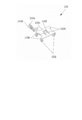
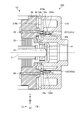
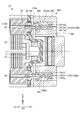
- FIG. 1 is a sectional view showing a motor using a terminal unit according to one of the embodiments of the present invention.
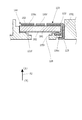
- FIG. 2 is a sectional view taken along the line AA of FIG.
- FIG. 3 is a perspective view showing a bracket and a plate.
- FIG. 4 is a perspective view showing a motor terminal.
- FIG. 5 is an exploded perspective view showing a structure including a bracket and a plate.
- FIG. 6 is a perspective view showing a PTC thermistor.
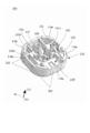
- FIG. 7 is a perspective view showing the terminal unit.
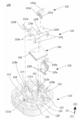
- FIG. 8 is a first exploded perspective view showing the terminal unit.
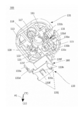
- FIG. 9 is a second exploded perspective view showing the terminal unit.
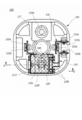
- FIG. 10 is a top view showing the terminal unit.
- FIG. 1 is a sectional view showing a motor using a terminal unit according to one of the embodiments of the present invention.
- FIG. 2 is a sectional view taken along the line AA of FIG.
- FIG. 3 is
- FIG. 11 is a perspective view showing the upper terminal member in a state of being fixed to the holder.
- FIG. 12 is a sectional view taken along line DD of FIG.
- FIG. 13 is a top view showing the terminal unit of the motor according to the second embodiment.
- FIG. 14 is a side view showing the terminal unit.
- FIG. 15 is a top view showing the terminal unit with external terminals connected.
- FIG. 16 is a sectional view taken along the line DD of FIG.
- FIG. 17 is a diagram for explaining the connection between the motor body and the terminal unit according to the second embodiment.
- FIG. 18 is a diagram for explaining a modified example of the connection between the motor body and the terminal unit according to the second embodiment.
- FIG. 19 is a top view showing a terminal unit according to a modification of the second embodiment.
- the direction parallel to the rotation axis of the motor may be referred to as the rotation axis direction.
- the rotation axis direction is sometimes referred to as the up-down direction (the direction in which the rotation axis projects from the motor frame is the upward direction).
- “Upper and lower”, “upper”, “lower” and the like are used for convenience in the case of focusing only on the motor, and the directions in the equipment in which the motor is mounted and the direction in which the motor is used. The posture is not limited in any way.
- FIG. 1 is a cross-sectional view showing a motor using a terminal unit according to one of the first embodiments of the present invention.
- FIG. 1 The cross section shown in FIG. 1 is a cross section taken along line BB in FIG. 2 described later.
- an arrow A1 indicates the rotation axis direction. In the arrow A1, the direction in which the arrow tip is located is upward.
- the motor 1 is, for example, a DC motor.
- the motor 1 roughly includes a motor body 1c and a terminal unit 100.
- the motor body 1c has a frame assembly 1a and a rotor rotatable with respect to the frame assembly 1a.
- the rotor is composed of a rotary shaft (shaft) 2 and an armature assembly 1b.
- the terminal unit 100 is used, for example, attached to the bottom portion (lower portion) of the motor body 1c.
- the armature assembly 1b is attached to the rotary shaft 2 and has an armature part 4 and a commutator part 6 and the like.
- the armature portion 4 has an armature core 5 having salient poles protruding in the radial direction and windings (not shown) wound around each salient pole.
- the commutator section 6 is provided near one end of the rotary shaft 2.
- the commutator section 6 includes a brush 25 provided on the frame assembly 1 a, a commutator 7 that contacts the brush 25, and the like.
- the frame assembly 1a is composed of a frame 10, a bracket 30, a plate 40, a magnet 50, and the like.
- the plate 40 includes a surface 40a facing the bracket 30 and a surface 40b facing the terminal unit 100 (see FIG. 5).
- the frame 10 has an upper end 10a (also referred to as one end or outer peripheral end 10a) forming a lid and a lower end 10b (other end or outer peripheral end 10b). It has a cylindrical shape which is covered with a lid portion having a surface.
- the opening at the lower end (the right end in FIG. 1) of the frame 10 is closed by the plate 40.
- the armature assembly 1b is housed in a housing formed by the frame 10 and the plate 40.
- the bracket 30 is attached to the inside of the plate 40.
- the bracket 30 holds the motor terminal 26 to which electric current is supplied from the outside.
- the motor terminal 26 is connected to the brush 25.
- the brush 25 is held in contact with the commutator 7.
- the rotary shaft 2 penetrates the lid portion (upper surface) of the frame 10. That is, the upper end portion (one end portion) of the rotating shaft 2 projects from the inside of the frame 10 to the outside, and the other portion of the rotating shaft 2 is housed inside the frame 10.
- a bearing 21 is held at the center of the upper surface of the frame 10.
- a bearing 22 is held at the center of the plate 40.
- a thrust washer 23 is arranged below the bearing 22.
- the rotating shaft 2 is rotatably supported with respect to the frame 10 by two bearings 21, 22 and a thrust washer 23.
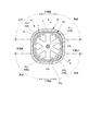
- FIG. 2 is a sectional view taken along the line AA of FIG.
- one cylindrical magnet 50 is provided.
- the magnet 50 is arranged inside the frame 10.
- the frame assembly 1 a has a sectional structure in which the outer peripheral surface 50 a of the magnet 50 is surrounded by the frame 10.
- the outer peripheral surface of the frame 10 serves as the outer peripheral surface of the motor body 1c.
- a plurality of magnets each having a magnetic pole element may be used.
- the frame 10 is made of a magnetic material.
- the frame 10 has a plurality of corner portions 12 and a surface portion (flat surface portion) 11 between two adjacent corner portions 12.
- the frame 10 has an outer shape having four flat portions 11 and four corner portions 12, respectively.
- Two flat surface portions 11 adjacent to each other in the circumferential direction are connected via one corner portion 12.
- One of the two planar portions 11 adjacent to each other in the circumferential direction is substantially perpendicular to the other.
- the corner portion 12 has a rounded shape (R shape).
- the frame 10 has a substantially square shape in a cross section perpendicular to the rotation axis 2.
- the frame 10 is formed in a square shape as a whole.
- the frame 10 has a substantially uniform thickness. That is, the inner peripheral surface 10b of the frame 10 is formed by connecting a plurality of flat portions formed by the flat surface portions 11 and rounded portions formed by the corner portions 12 to form a square shape.
- the magnet 50 is, for example, a bond magnet formed using a known ferrite material or a rare earth material such as neodymium or samarium and a known resin material.
- the magnet 50 is not limited to the bond magnet, and may be a sintered magnet, for example.
- the magnet 50 has magnetic pole elements 61 (N pole 61a, S pole 61b, N pole 61c, S pole 61d). That is, the magnet 50 has the same number of magnetic pole elements 61 as the number of the corners 12 of the motor body 1c.
- the magnetic pole elements 61 are arranged in the circumferential direction so that the polarities are staggered.
- the four magnetic pole elements 61 are arranged at the four corners 12 of the frame 10 such that the magnetic pole elements 61 face each other. That is, the switching portions of the four magnetic pole elements 61 are at positions overlapping the flat surface portion 11 of the frame 10 in the radial direction.
- the magnet 50 has a rounded outer peripheral surface 50 a along the inner peripheral surface 10 b of the frame 10 of the corner portion 12. Further, the magnet 50 has a cylindrical inner peripheral surface 50b. A slight air gap is provided between the inner peripheral surface 50b of the magnet 50 and the amateur core 5.
- the magnet 50 is adhered to the inner peripheral surface 10b of the frame 10 with an adhesive (not shown).
- the magnet 50 is housed inside the frame 10 through the lower opening of the frame 10 and is bonded to the inner peripheral surface 10 b of the frame 10.
- the armature assembly 1b is housed inside the frame 10 and the bracket 30 and the plate 40 are attached to the frame 10 to assemble the motor body 1c.
- FIG. 3 is a perspective view showing the bracket 30 and the plate 40.
- FIG. 3 upper portions of the bracket 30 and the plate 40 are shown.
- two motor terminals 26 are attached to the bracket 30.
- One end of each brush 25 is connected to the motor terminal 26.
- the two brushes 25 are supported by the motor terminals 26, respectively.
- the other end of each brush 25 contacts the commutator 7 of the armature assembly 1b.
- the bracket 30 is formed of, for example, a resin member.
- the bracket 30 has a thickness in the rotation axis direction.
- the bracket 30 has a tubular portion having an opening 35 through which the rotary shaft 2 passes.
- the bracket 30 is a tubular portion having an opening 35 in the center.
- the brush 25 is arranged in the opening 35.
- the rotary shaft 2 penetrates the opening 35.
- the bracket 30 has an outer peripheral surface 30a having an annular closed shape. That is, the tubular portion has the outer peripheral surface 30a.
- the outer peripheral surface 30a of the tubular portion has roughly the same shape as the inner peripheral surface 10b of the frame 10 when viewed from the rotation axis direction (in plan view). That is, the bracket 30 has four corner portions 32 and a flat surface portion 31 provided between two adjacent corner portions 32. The outer peripheral surface 30a of the tubular portion is provided on the four corner portions 32 and the four flat portions. As shown in FIG. 1, the outer peripheral surface 30 a of the bracket 30 extends toward the magnet 50 in the rotation axis direction. The length of the bracket 30 in the rotation axis direction is, for example, slightly larger than the dimension of the brush 25 in the rotation axis direction. The brush 25 is housed inside the opening 35. With the bracket 30 attached to the frame 10, the outer peripheral surface 30 a of the bracket 30 is in contact with the inner peripheral surface 10 b of the frame 10.
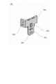
- FIG. 4 is a perspective view showing the motor terminal 26.
- the motor terminal 26 has a brush fixing portion 26a to which the brush 25 is fixed, a holding portion 26b held by the bracket 30, and a downward extending from the holding portion 26b (extension of the holding portion 26b. Terminal piece 26c extending in a direction intersecting the direction).
- the motor terminal 26 is made of a metal plate.
- a saw-toothed protrusion (hereinafter referred to as a retaining protrusion) 26d protruding laterally is provided at a portion of the side edge of the terminal piece 26c near the holding portion 26b.
- a hole 26e is formed in the terminal piece 26c which is a part of the motor terminal. Instead of the hole 26e, an engaged portion having an uneven shape may be provided.
- FIG. 5 is an exploded perspective view showing a structure including the bracket 30 and the plate 40.
- FIG. 5 only one set of the assembly of the brush 25 and the motor terminal 26 is shown.
- the holding portion 26 b is held by the bracket 30 by inserting the motor terminal 26 to which the brush 25 is attached from the upper side to the lower side of the bracket 30.
- the retainer protrusion 26d is caught on a part of the bracket 30 so that the motor terminal 26 does not fall out of the bracket 30.
- the terminal piece 26c projects from the bracket 30 toward the plate 40 (downward).
- the terminal piece 26 c penetrates the terminal hole portion 42 formed in the plate 40 and projects below the plate 40. That is, the terminal piece 26c projects downward from the bottom of the motor body 1c.
- the plate 40 is provided with the hole 43 in addition to the terminal hole 42.
- a projection (not shown) formed on the lower surface of the bracket 30 is fitted into the hole 43. Further, a fastening member is attached to the hole portion 43 as described later.
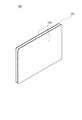
- FIG. 6 is a perspective view showing the PTC thermistor 180.
- a PTC thermistor 180 is mounted on the terminal unit 100 as an electronic component. As shown in FIG. 6, the PTC thermistor 180 has a flat plate shape.
- the PTC thermistor 180 is, for example, a single plate type. That is, the PTC thermistor 180 has two surfaces having a larger area than the other surfaces. In other words, the PTC thermistor 180 has a rectangular parallelepiped shape having an upper surface and a lower surface having a larger area than the other side surfaces.
- the PTC thermistor 180 is configured by sandwiching both surfaces (upper surface and lower surface) of a single plate-shaped core 181 with electrode plates 182.
- the electrode plate 182 forms two surfaces of the PTC thermistor 180.
- the PTC thermistor 180 may have a laminated plate shape in which a plurality of layers of cores are laminated, for example.
- FIG. 7 is a perspective view showing the terminal unit 100.
- FIG. 8 is a first exploded perspective view showing the terminal unit 100.
- FIG. 9 is a second exploded perspective view showing the terminal unit 100.
- FIG. 10 is a top view showing the terminal unit 100.
- FIGS. 7, 8 and 9 a view of the terminal unit 100 viewed from above is shown.
- the terminal unit 100 includes a holder 110, an upper terminal member 133, a lower terminal member 135, a third terminal member 131, and a PTC thermistor 180.
- the holder 110 includes an outer peripheral end portion 110a that faces the outer peripheral end portion 10b of the frame 10 in the axial direction of the motor 1.
- the outer peripheral end 110a of the holder 110 faces the outer peripheral end 10b of the frame 10 in the axial direction of the motor 1 and the surface 110b in the axial direction of the motor 1 from the surface 110b toward the plate 40 that is the bottom of the motor body 1c.
- a plurality of projecting portions 110c that project are provided. These protrusions 110c face the plate 40 that is the bottom of the motor body 1c, and contact the inner surface of the outer peripheral end 10b of the frame 10.
- the terminal unit 100 is positioned (guided) with respect to the frame 10 by the protrusion 110c.
- the holder 110 is made of resin, for example.
- the upper terminal member 133, the lower terminal member 135, the third terminal member 131, and the PTC thermistor 180 are attached to the holder 110.
- the outer peripheral surface of the holder 110 has, for example, four corner portions 102 and a flat surface portion 101 provided between two adjacent corner portions 102, similarly to the frame 10 of the motor body 1c.
- the holder 110 has an opening portion (hereinafter, referred to as an upper insertion portion) 113 into which the upper terminal is inserted and an opening portion (hereinafter, referred to as a lower insertion portion) into which the lower terminal is inserted. 115) and an opening portion (hereinafter, referred to as a third terminal insertion portion) 111 into which the third terminal is inserted are formed. Respective opening portions (hereinafter collectively referred to as insertion portions) 113 and 115 and a third terminal insertion portion 111 are formed.
- Each of the insertion portions 113, 115, 111 has a groove shape into which the corresponding terminal member 133, 135, 131 can be inserted from the upper side of the holder 110 (that is, the inside of the holder 110).
- the insertion portions 113, 115, 111 are provided with hook-shaped claw portions 113a, 115b, 111a, 111b that hang on the upper ends of the inserted terminal members 133, 135, 131, respectively. Since the claw portions 113a, 115b, 111a, 111b are hooked on the upper ends of the terminal members 133, 135, 131, the terminal members 133, 135, 131 are prevented from coming off the holder 110.
- a hole 117 is formed in the center of the holder 110.
- the hole 117 is formed on an extension of the rotary shaft 2 of the motor body 1c. That is, the hole 117 is formed so that the central portion of the plate 40 of the motor body 1c can be seen from below the motor 1. Thereby, even if the process of assembling the device using the motor 1 includes the process of applying a downward force to the rotation shaft of the motor body 1c, the center of the plate 40 can be easily passed through the hole 117, for example. The part can be supported.
- a recess (an example of a fixed portion) 118 extending upward from the lower surface of the holder 110 is provided between the hole 117 and one flat surface portion 101.
- the recess 118 is formed so as to project upward when viewed from the inside of the holder 110.
- the upper end surface of the recess 118 is at a position where it can come into contact with the bottom surface of the plate 40 when the holder 110 is attached to the motor body 1c.
- a hole 118a is formed on the upper end surface of the recess 118.
- a hole 43 is provided in the plate 40 at a position facing the recess 118, and the holder 110 and the plate 40 can be coupled through the recess 118 by using a fastening member such as a screw or a tack member. Thereby, the holder 110 and the motor main body 1c can be coupled.
- the hole 117 and the recess 118 may not be provided.
- the method of coupling the holder 110 and the motor body 1c using the recess 118 may not be used.
- a method of attaching the holder 110 to the motor body 1c only a method of engaging the motor terminal 26 with the upper terminal member 133 and the third terminal member 131, which will be described later, may be adopted.
- the holder 110 is provided with an accommodating portion 121 in which the PTC thermistor 180 is accommodated.
- the accommodating part 121 is provided, for example, near one flat part 101.
- the accommodating portion 121 has a substantially rectangular plate-shaped PTC thermistor 180 that is substantially perpendicular to the rotation axis direction, and one side surface of the PTC thermistor 180 is substantially parallel to the one flat surface portion 101 and above the holder 110. It is formed so as to be arranged from.
- a wall 122 facing the side surface of the PTC thermistor 180 arranged in the housing 121 is formed near the housing 121.
- the wall 122 is formed of a resin member that constitutes the holder 110.
- a hole 123 into which the arms 133h and 133j of the upper terminal member 133 are inserted is formed at a position farther from the PTC thermistor 180 than the wall 122, as described later.
- a contact protrusion 121f protruding upward is formed on the bottom surface of the accommodating portion 121.
- the contact protrusion 121f is formed so as to face the lower surface of the PTC thermistor 180 arranged in the housing portion 121.
- the contact protrusion 121f is formed so as to contact one portion of the lower surface of the PTC thermistor 180 arranged in the housing portion 121, which is close to the side circumferential surface.
- An opening 128 that vertically penetrates the holder 110 is provided on the bottom surface of the housing 121.
- the opening 128 is formed so as to face the surface of the PTC thermistor 180 arranged in the housing 121.
- the outside of the holder 110 and the inside of the holder 110 are connected via an opening 128.
- the opening 128 By forming the opening 128 in this way, the temperature of the outside air is easily transmitted to the PTC thermistor 180. Therefore, the temperature of the PTC thermistor 180 easily rises with respect to the temperature rise outside the motor 1, and when the temperature rises outside the motor 1, the PTC thermistor 180 can quickly limit the current.
- the PTC thermistor 180 is arranged in the accommodation section 121.
- the surface of the PTC thermistor 180 faces the direction of the rotation axis of the motor. That is, one of the two electrode plates 182 of the PTC thermistor 180 faces upward and the other faces downward.
- the surface of the PTC thermistor 180 is perpendicular to the rotation axis direction or at an angle close to perpendicular to the rotation axis direction.
- the PTC thermistor 180 is arranged not in parallel to the rotation axis direction but in a posture inclined with respect to the rotation axis direction.
- the third terminal member 131 is a metal plate formed by pressing or the like.
- the third terminal member 131 has a strip shape that is bent at an approximately right angle in an “L” shape.
- One end of the third terminal member 131 is a motor side terminal piece 131 a connected to the motor terminal 26.
- the other end of the third terminal member 131 is an external terminal surface 131b exposed to the outside of the holder 110.
- the motor side terminal piece 131a is provided with a protrusion 131d as an engaging means.
- the protrusion 131d is formed so that a part of the motor-side terminal piece 131a is pushed out in a direction perpendicular to the motor-side terminal piece 131a so as to rise from the motor-side terminal piece 131a.
- the protrusion 131d is formed so as to protrude toward the motor terminal 26 connected to the motor-side terminal piece 131a as described below.
- the protrusion 131d projects in a direction substantially perpendicular to the rotation axis direction.
- the lower terminal member 135 is a metal plate formed by pressing or the like.
- the lower terminal member 135 has a shape in which a strip-shaped metal plate is bent at two locations at a substantially right angle.
- One end of the lower terminal member 135 is an external terminal surface 135b exposed to the outside of the holder 110.
- the other end of the lower terminal member 135 is an element-side terminal surface 135c extending toward the lower surface of the PTC thermistor 180.
- the element-side terminal surface 135c is located below the PTC thermistor 180.
- the element-side terminal surface 135c is located away from the position where the contact protrusion 121f is formed.
- Two contact protrusions 135f that project upward are formed on the element-side terminal surface 135c.
- Each contact protrusion 135f is formed so as to face the lower surface of the PTC thermistor 180 arranged in the housing 121.
- Each of the contact protrusions 135f is formed so as to come into contact with one portion of the lower surface of the PTC thermistor 180 arranged in the housing portion 121, near the side peripheral surface.
- the element-side terminal surface 135c of the lower terminal member 135 contacts the lower electrode plate 182 of the PTC thermistor 180.
- the contact protrusions 135f are arranged at positions apart from the contact protrusions 121f of the holder 110.
- the PTC thermistor 180 arranged in the housing portion 121 contacts three points of one contact portion (contact protrusion) 121f and two contact portions (contact protrusion) 135f.
- the triangle connecting the three points with which the PTC thermistor 180 contacts and the central portion of the PTC thermistor 180 overlap when viewed from the rotation axis direction.
- the external terminal surface 131b of the third terminal member 131 and the external terminal surface 135b of the lower terminal member 135 are located near the flat surface portion 101 different from the flat surface portion 101 near the PTC thermistor 180. Facing each other.
- the external terminal surfaces 131b and 135b are exposed to the outside of the holder 110, and a voltage can be applied to the external terminal surfaces 131b and 135b from an external circuit or the like to supply power to the motor 1.
- lead wires are connected to each of the external terminal surfaces 131b and 135b (not shown).
- the lead wire is connected to the external terminal surfaces 131b and 135b by a method such as soldering or resistance welding.
- the motor 1 can be wired so that it can be driven.
- the lower terminal member 135 and the third terminal member 131 may have female terminals or male terminals that can be connected to an external circuit, instead of the external terminal surfaces 131b and 135b.
- the female terminal may be configured to be exposed to the outside of the holder 110 so as to contact the male terminal inserted into the terminal unit 100 from the outside, for example.
- the male terminal may be configured to project from the holder 110 and to be able to connect a female terminal provided on an external circuit or a lead wire, for example.
- the upper terminal member 133 is a metal plate formed by pressing or the like.
- the upper terminal member 133 has a plate-shaped plate portion 133c that covers the upper surface of the PTC thermistor 180, and a belt-shaped motor-side terminal piece 133a that is bent and extends from the plate portion 133c.
- the motor-side terminal piece 133a is connected to the motor terminal 26.
- the upper terminal member 133 is fixed to the holder 110.
- the motor side terminal piece 133a is provided with a protrusion 133d as an engaging means.
- the protrusion 133d is formed so that a part of the motor-side terminal piece 133a is pushed out in a direction perpendicular to the motor-side terminal piece 133a so as to rise from the motor-side terminal piece 133a.
- the protrusion 133d is formed so as to protrude toward the motor terminal 26 connected to the motor-side terminal piece 133a as described later.
- the protrusion 133d projects in a direction substantially perpendicular to the rotation axis direction.
- a pressing portion 133f is formed at the center of the plate portion 133c.
- the pressing portion 133f has a rectangular shape whose one side is connected to the plate portion 133c. That is, there is a gap between the three sides of the peripheral edge of the pressing portion 133f and the plate portion 133c.
- the pressing portion 133f has a cantilever shape supported by the plate portion 133c at one side portion connected to the plate portion 133c.
- the pressing portion 133f has a tongue shape supported by the plate portion 133c at one side portion connected to the plate portion 133c.
- the pressing portion 133f can bend with respect to the plate portion 133c. That is, the upper terminal member 133 has flexibility.
- the pressing portion 133f is bent slightly downward from the plate portion 133c.
- the pressing portion 133f contacts the surface of the PTC thermistor 180. That is, the pressing portion 133f comes into contact with the upper electrode plate 182 of the PTC thermistor 180. Accordingly, the upper terminal member 133 is electrically connected to the lower terminal member 135 via the PTC thermistor 180.
- the side edge of the plate 133c is provided with two arms 133h and two arms 133h that are bent from the plate 133c and extend downward.
- the arm portion 133j extends downward longer than the arm portion 133h.
- the four arm portions 133h and 133j are inserted into the four hole portions 123 adjacent to the housing portion 121 with the wall 122 interposed therebetween.
- Sawtooth-shaped retainer protrusions 133k protruding laterally are provided on the side edges of the arm portions 133h and 133j.
- the upper terminal member 133 is fixed to the holder 110 by inserting the four arm portions 133h and 133j into the four hole portions 123 from above to below. At this time, the retainer protrusion 133k is caught by a part of the holder 110 so that the upper terminal member 133 does not fall out of the holder 110.
- FIG. 11 is a perspective view showing the upper terminal member 133 fixed to the holder 110.
- FIG. 11 only the upper terminal member 133 is shown. After the upper terminal member 133 is inserted into the holder 110, the tip ends of the two arm portions 133j are bent. That is, since the tip of the arm 133j is bent, the arm 133j cannot be pulled out upward from the hole 123. Thereby, the upper terminal member 133 is securely held by the holder 110.
- FIG. 12 is a sectional view taken along the line DD of FIG.
- the pressing portion 133f comes into contact with the surface of the PTC thermistor 180, and the PTC thermistor 180 is attached to the holder 110. Press down.
- the pressing portion 133f is in contact with the central portion of the upper electrode plate 182 of the PTC thermistor 180.
- the PTC thermistor 180 is supported from below by one contact protrusion 121f and two contact protrusions 135f at three points near the side edge of the lower electrode plate 182.
- the pressing portion 133f is bent upward by the PTC thermistor 180 above a natural state (a state in which no force is applied to the upper terminal member 133). Therefore, the PTC thermistor 180 is pressed toward the contact protrusions 121f and 135f by the restoring force of the pressing portion 133f.
- the lower terminal member 135 is in contact with the other of the electrode plates 182 when the PTC thermistor 180 is pressed against the holder 110 by the pressing portion 133f. In this way, the PTC thermistor 180 is maintained in a state where the PTC thermistor 180 is surely in contact with the upper terminal member 133 and the lower terminal member 135.
- the arms 133h and 133j of the upper terminal member 133 inserted into the hole 123 and the side surface of the PTC thermistor 180 face each other via the wall 122.
- the arms 133h and 133j and the PTC thermistor 180 do not come into contact with each other, so that the PTC thermistor 180 in the power feeding path of the motor 1 is maintained in a surely functioning state.
- terminals other than the upper terminal member 133 such as the lower terminal member 135 and the third terminal member 131, are arranged so as to pass in the vicinity of the PTC thermistor 180, the PTC thermistor 180 and the terminals are connected to each other like the wall 122.
- a wall may be provided between the terminals to prevent the terminals and the PTC thermistor 180 from unintentionally coming into contact with each other.
- An engaging portion that engages with a portion of the bottom is provided in a portion of the terminal unit 100 that faces the bottom of the motor body 1c.
- the terminal unit 100 is fixed to the bottom of the motor body 1c by engaging the engaging portion with the engaged portion provided on the bottom side of the motor body 1c.
- the terminal piece 26c of the motor terminal 26 protruding downward from the plate 40 that is the bottom of the motor body 1c is provided with a hole 26e that is an engaged portion.
- Two terminal pieces 26c project downward from the motor body 1c.
- the motor-side terminal piece 133a of the upper terminal member 133 and the motor-side terminal piece 131a of the third terminal member 131 are exposed so as to correspond to the respective terminal pieces 26c.
- the motor-side terminal pieces 131a, 133a are provided with protrusions 131d, 133d serving as engaging portions.
- a terminal insertion space is provided on the side where the protrusions 131d, 133d project.
- the protrusions 131d and 133d come into contact with the surfaces of the terminal pieces 26c, so that at least one of the motor side terminal pieces 131a and 133a and the terminal piece 26c is slightly bent.
- the protrusions 131d and 133d and the hole 26e of the terminal piece 26c overlap each other in the direction perpendicular to the rotation axis direction, the protrusions 131d and 133d fit into the hole 26e and engage with each other.
- the terminal unit 100 is fixed to the motor body 1c by engaging the terminal piece 26c on the motor body 1c side with the motor side terminal pieces 131a and 133a on the terminal unit 100 side.
- a concave engaged portion may be provided instead of the hole 26e. That is, the terminal unit 100 includes the motor-side terminal piece 131a and the motor-side terminal piece 133a as a motor terminal connecting portion electrically connected to the motor terminal 26.
- the motor terminal 26 and the motor side terminal piece 131a are fitted together, and the other motor terminal 26 and the motor side terminal piece 133a are fitted together to connect the motor body 1c and the terminal unit 100. ..
- the motor-side terminal piece 131a is provided with a protrusion 131d as an engaging means
- the motor-side terminal piece 133a is provided with a protrusion 133d as an engaging means.
- the surface of the motor terminal 26 facing a part (for example, the protrusion 131d, the protrusion 133d) of the surface of the motor terminal connecting portion (the motor side terminal piece 131a, the motor side terminal piece 133a) has a hole as an engaged portion. 26e is provided.
- the motor terminal 26 may be provided with a recess as an engaged portion. Further, the motor main body 1c and the terminal unit 100 may be fitted to each other only at the fitting portion between the motor terminal 26 and the motor terminal connecting portion (motor-side terminal piece 131a, motor-side terminal piece 133a).
- the plate 40 which is the bottom of the motor body 1c, and the holder 110 are separable from each other.
- the motor body 1c includes a frame 10, and the frame 10 and the holder 110 can be separated from each other.
- the outer peripheral end 10b of the frame 10 and the outer peripheral end 110a of the holder 110 which are opposed to each other, are separable from each other.
- the terminal unit can be freely changed according to the application of the motor. Alternatively, it is possible to prevent the vibration of the motor from propagating to the terminal unit.
- the terminal unit 100 is said to house the wiring portion that electrically connects the motor terminal 26 and the external terminal surfaces 131b and 135b. be able to. That is, the wiring portion of the first system that electrically connects the one motor terminal 26 and the external terminal surface 131b is configured by the third terminal member 131.
- the second system wiring portion that electrically connects the other motor terminal 26 and the external terminal surface 135 b is configured by the upper terminal member 133, the PTC thermistor 180, and the lower terminal member 135.
- the PTC thermistor 180 is provided in the middle of the wiring section of the second system.
- the mode of the engaging part and the engaged part with which the engaging part engages is not limited to this.
- the motor body 1c side does not have a male type terminal as in the present embodiment, but has a female type terminal as an engaged portion, and the female type terminal of the motor body 1c is projected upward to the terminal unit 100.
- a male terminal piece that engages with may be provided as the engaging means.
- a projecting engaged portion may be formed on the terminal piece on the motor body 1c side, and a hole-shaped or concave engaging portion may be formed on the terminal piece on the terminal unit 100 side.
- the engaged portion on the side of the motor body 1c is not limited to the terminal piece 26c, but is provided at an appropriate portion such as a portion of the plate 40 of the motor body 1c, a portion of the frame 10, a portion of the bracket 30. Just do it.
- the engaging portion on the side of the terminal unit 100 is not limited to the motor-side terminal pieces 131a and 133a, and may be provided on an appropriate portion such as a part of the holder 110 or a member attached to the holder 110 or the like. ..
- the PTC thermistor 180 can be arranged in a posture substantially vertical to the rotation axis direction. Therefore, the dimension of the motor 1 in the rotation axis direction can be shortened.
- the upper surface of the PTC thermistor 180 faces the plate 40 that is the bottom surface of the housing of the motor body 1c. That is, since the PTC thermistor 180 is arranged so that the area where the heat of the motor body 1c can be detected is large, the detection accuracy of the PTC thermistor 180 is improved.
- the PTC thermistor 180 is housed in the terminal unit 100 that can be externally attached to the motor body 1c that functions as a motor even by itself.
- the EMC (electromagnetic compatibility) noise countermeasure becomes insufficient.
- switching noise of the commutator / brush may come out of the motor as radiation noise through the hole in the bottom plate.
- the motor housing it is not necessary to provide the motor housing with a hole through which the PTC thermistor passes. Therefore, the motor 1 including the PTC thermistor 180 can be manufactured without impairing the EMC performance of the motor body 1c.
- the motor 1 can be manufactured by assembling the motor body 1c and the terminal unit 100 after manufacturing the motor body 1c and the terminal unit 100, respectively. Therefore, the manufacturing line for manufacturing the motor main body 1c without the PTC thermistor 180 and the manufacturing line for the terminal unit 100 can be separated. The motor body 1c can be efficiently manufactured on the same manufacturing line regardless of whether it is used alone as a motor or as the motor 1 with the PTC thermistor 180.
- the terminal unit 100 is fixed to the motor body 1c by engaging the bottom of the motor body 1c. Therefore, the terminal units 100 having the same configuration are attached to various types of motor main bodies 1c having the bottoms configured in the same manner and having different lengths of the windings and the rotating shafts, and the windings and the rotating shafts are respectively attached. It is possible to manufacture the motor 1 with the PTC thermistor 180 having different specifications such as. Therefore, it is not necessary to prepare a separate manufacturing line for each motor having different specifications, and the terminal units 100 used for various motor bodies can be manufactured on the same manufacturing line. Can be manufactured.
- the PTC thermistor 180 is incorporated in the power supply line of the motor 1 without using solder or the like. Therefore, it is possible to easily manufacture the motor 1, and it is possible to prevent the occurrence of defects due to poor solder connection or the like.
- the terminal unit 100 In manufacturing the terminal unit 100, while the upper terminal member 133 and the lower terminal member 135 are in contact with the electrode plate 182 of the PTC thermistor 180, one of them is slid relative to the other so that they are relatively moved. There is no such process. Therefore, the electrode plate 182 is not scratched by the upper terminal member 133 and the lower terminal member 135, and the PTC thermistor 180 is not damaged when the terminal unit 100 is manufactured. Therefore, the terminal unit 100 can be easily manufactured. You can
- the central part of the upper surface of the PTC thermistor 180 is pressed downward by the pressing part 133f.
- the lower surface of the PTC thermistor 180 is supported by the contact protrusion 121f in the vicinity of one side edge, and the contact protrusion 135f is provided in the vicinity of the opposite side edge with the central portion sandwiched in the direction perpendicular to the rotation axis direction. It is supported. That is, the PTC thermistor 180 is held by the holder 110 in such a state that the load is applied to the central portions of the support beams at both ends, and the state in which the PTC thermistor 180 is reliably in contact with the contact protrusion 135f of the lower terminal member 135 is maintained.
- a plate type can be used as the PTC thermistor 180. Since it is possible to use the PTC thermistor 180 which is less expensive than the case where the surface mount type PTC thermistor is used, the manufacturing cost of the motor 1 can be reduced. Further, since the plate type PTC thermistor 180 can be used, an appropriate shape can be used according to the shape of the terminal unit 100 and the application of the motor 1. Therefore, the degree of freedom in the layout of the components in the terminal unit 100 can be increased.
- the basic configuration of the motor 1 in the second embodiment is the same as that in the first embodiment, so the description here will not be repeated.
- the configuration of the motor body 1c is similar to that of the first embodiment.
- the second embodiment is different from the first embodiment in that a terminal unit 200 having a layout of terminals and the like different from that of the above-described terminal unit 100 is used.
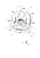
- FIG. 13 is a top view showing the terminal unit 200 of the motor 1 according to the second embodiment.
- FIG. 14 is a side view showing the terminal unit 200.
- FIG. 13 the first terminal member 231 and the second terminal member 235 are hatched, and the upper terminal member 133, the PTC thermistor 180, and the motor terminal 26 on the motor body 1c side are indicated by a chain double-dashed line. It is shown.
- the X direction shown in FIG. 13 is a direction perpendicular to the pair of flat surface portions 201b and 201d
- the Y direction is a direction perpendicular to the pair of flat surface portions 201a and 201c, that is, a direction perpendicular to the X direction. ..
- the terminal unit 200 electrically connects the holder 210, the PTC thermistor 180 and the terminal portion 330b fixed to the holder 210, the motor terminal 26 of the motor body 1c, and the terminal portion 330b.
- a wiring section for The terminal portion 330b includes two terminals 231b and 235b (first terminal 231b and second terminal 235b) having contact surfaces that come into contact with the external terminals 380.
- the wiring portion is a wiring portion of the first system that electrically connects the first terminal 231b and one motor terminal 26, and a wiring portion that electrically connects the second terminal 235b and the other motor terminal 26. Two systems, including a two-system wiring section, are provided. Each of the wiring parts of the first system and the second system includes a wiring formed of a metal member.
- the terminal unit 200 is provided with a first terminal member 231, an upper terminal member 133, and a second terminal member 235.
- the upper terminal member 133 has a structure similar to that of the first embodiment.
- the first terminal member 231 and the second terminal member 235 are used instead of the third terminal member 131 and the lower terminal member 135 of the first embodiment.
- the wiring part of the first system is composed of the first terminal member 231.
- the wiring part of the second system includes an upper terminal member 133, a PTC thermistor 180, and a second terminal member 235. That is, the PTC thermistor 180 is provided in the middle of the second wiring section.
- a first terminal member 231, an upper terminal member 133, a second terminal member 235, and a PTC thermistor 180 are attached to the holder 210. ..
- the holder 210 is made of resin, for example.
- the outer peripheral surface of the holder 210 is, for example, similar to the frame 10 of the motor body 1c, four corner portions 202 and four flat surface portions 201 provided between two adjacent corner portions 202 (lower side in FIG. 13). In the counterclockwise direction from the surface of FIG.
- the holder 210 is formed with a groove shape into which each terminal member 231, 133, 235 is inserted. Further, claw portions for fixing the terminal members 231 and 133 to the holder 210 are formed. Although these positions differ depending on the positions of the terminal members 231, 133, 235, the functions and shapes are the same as those in the first embodiment.
- the holder 210 is provided with the accommodation portion 121 in which the PTC thermistor 180 is accommodated.
- the accommodating part 121 is provided at a position close to one flat part 201b.
- the shape of the housing portion 121 and the housing structure of the PTC thermistor 180 electrically connected to the two terminal members 133 and 235 are the same as those in the first embodiment.
- the terminal portion 330b is arranged at a position close to one flat surface portion 201d. That is, the terminal portion 330b and the PTC thermistor 180 are arranged to face each other in the radial direction. In other words, the terminal portion 330b and the PTC thermistor 180 are arranged at positions facing each other with respect to the rotating shaft 2 (shown by a chain double-dashed line in FIG. 13).
- the PTC thermistor 180 is located near one of the two flat surface portions 201b and 201d that face each other with the rotary shaft 2 in between, and the terminal portion 330b is located near the other.
- the first terminal member 231 is a metal plate formed by pressing or the like.
- One end portion (hereinafter, referred to as a tip end portion) of the first terminal member 231 serves as a first terminal 231b of the terminal portion 330b.
- the other end of the first terminal member 231 (hereinafter referred to as the tip) is a motor-side terminal piece 231a connected to the motor terminal 26.
- the specific shape of the motor side terminal piece 231a is substantially the same as the motor side terminal piece 131a of the third terminal member 131 in the first embodiment.
- a wiring 231d is provided between the first terminal 231b and the motor side terminal piece 231a.
- the wiring 231d and the motor side terminal piece 231a electrically connect the first terminal 231b and the motor terminal 26 engaged with the motor side terminal piece 231a.
- the second terminal member 235 is a metal plate formed by pressing or the like.
- One end portion (hereinafter, referred to as a tip end portion) of the second terminal member 235 serves as a second terminal 235b of the terminal portion 330b.
- the other end (hereinafter, referred to as a tip) of the second terminal member 235 serves as an element-side terminal surface 235c extending toward the lower surface of the PTC thermistor 180.
- the specific shape of the element-side terminal surface 235c is substantially the same as that of the element-side terminal surface 135c.
- a wiring 235d is provided between the second terminal 235b and the element side terminal surface 235c.
- the second terminal 235b and the PTC thermistor 180 that is in contact with the element-side terminal surface 235c are electrically connected by the wiring 235d and the element-side terminal surface 235c. That is, the second terminal 235b is electrically connected to the motor terminal 26 engaged with the motor-side terminal piece 133a of the upper terminal member 133 via the PTC thermistor 180.
- the terminal unit 200 includes the motor-side terminal piece 231a of the first terminal member 231 and the upper side described in the first embodiment as a motor terminal connection portion that is electrically connected to the motor terminal 26.
- the terminal member 133 includes a motor-side terminal piece 133a. In the second embodiment, the one motor terminal 26 and the motor-side terminal piece 231a are fitted together, and the other motor terminal 26 and the motor-side terminal piece 133a are fitted together to form the motor body 1c and the terminal unit. 200 is connected.
- the first terminal member 231 and the second terminal member 235 may not be integrally formed by molding a metal plate.
- the first terminal 231b and the motor may be formed by wiring formed of a conductive wire.
- the side terminal piece 231a and the second terminal 235b and the element side terminal surface 235c may be connected to each other.
- the first terminal 231b and the second terminal 235b are formed such that the longitudinal direction thereof is the X direction. That is, as shown in FIG. 13, in a top view, the directions from the flat surface portion 201d to the flat surface portion 201b on the opposite side with the rotary shaft 2 interposed therebetween are respectively the first terminal 231b and the second terminal 235b. It is in the longitudinal direction.
- the first terminal 231b and the second terminal 235b are planes that pass through the rotation axis 2 and are perpendicular to the Y direction in a top view (that is, a plane that is parallel to the plane portion 201c or the plane portion 201a and that passes through the rotation axis 2). ) Has a shape that is symmetrical with respect to.
- the first terminal 231b extends from the wiring 231d held by the holder 210 to a position close to the flat surface portion 201d while being inclined so as to gradually approach the rotating shaft 2 in the Y direction.
- the tip portion of the first terminal 231b is bent so as to be separated from the rotating shaft 2 in the Y direction.
- the motor terminal 26 has a shape in which the dimension in the X direction is larger than the dimension in the Y direction. That is, the longitudinal direction of the cross section perpendicular to the vertical direction of the motor terminal 26 is the X direction.
- the longitudinal direction of the cross section perpendicular to the vertical direction of the motor terminal 26 and the longitudinal direction of the first terminal 231b and the second terminal 235b are the same direction.
- the first terminal 231b can be bent so that the tip portion is displaced in the Y direction. That is, the two terminals 231b and 235b can approach or separate from each other.
- the first terminal 231b is located inside an insertion port (hereinafter referred to as an external terminal insertion portion) 281 in which an external terminal provided in the holder 210 is inserted.
- the external terminal insertion portion 281 is an opening portion and is also referred to as an insertion portion hereinafter.
- the external terminal insertion portion 281 has an inner wall surface 281b and an outer wall surface 281c each having a surface (that extends in the longitudinal direction of the first terminal 231) that is parallel to the flat surface portion 201c.
- the inner wall surface 281b is inside the first terminal 231b in the Y direction (closer to the rotating shaft 2), and the outer wall surface 281c is outside the first terminal 231b in the Y direction (away from the rotating shaft 2). Side).
- the second terminal 235b is located inside an insertion port (hereinafter, referred to as an external terminal insertion portion) 282 provided in the holder 210 and into which an external terminal is inserted.
- the external terminal insertion portion 282 is an opening portion and is also referred to as an insertion portion hereinafter.
- the external terminal insertion portion 282 has an inner wall surface 282b and an outer wall surface 282c, each of which has a surface (extending in the longitudinal direction of the second terminal 235, that is, parallel to the flat surface portion 201c).
- the inner wall surface 282b is inside the second terminal 235b in the Y direction, and the outer wall surface 282c is outside the second terminal 235b in the Y direction.
- the terminal portion 330b includes an external terminal insertion portion 281 as an insertion portion and a first terminal 231b as a terminal provided inside the external terminal insertion portion 281. Further, the terminal portion 330b includes an external terminal inserting portion 282 as an inserting portion and a second terminal 235b as a terminal provided inside the external terminal inserting portion 282.
- the first terminal 231b extends in the longitudinal direction (X direction) of the external terminal insertion portion 281 and the second terminal 235b extends in the longitudinal direction (X direction) of the external terminal insertion portion 282. is doing.
- the external terminal inserting portion 281 and the first terminal 231b and the external terminal inserting portion 282 and the second terminal 235b are symmetrical with respect to the rotation axis 2 in the Y direction so as to face each other in the Y direction. It is located in.
- the two motor terminals 26 are located between the two terminals 231b, 235b and the PTC thermistor 180 in the longitudinal direction of the two terminals 231b, 235b, that is, the X direction.
- the motor terminal 26 on the plane portion 201c side connected to the motor side terminal piece 231a and the motor terminal 26 on the plane portion 201a side connected to the motor side terminal piece 133a are opposed to each other in the radial direction.
- the two motor terminals 26 are located symmetrically with respect to the rotating shaft 2 in the Y direction.
- the wiring part of the first system is arranged between the motor terminal 26 and the first terminal 231b on the flat surface 201c side.
- the wiring portion of the second system extends from the motor terminal 26 on the plane portion 201a side to the plane portion 201b side via the PTC thermistor 180, and then bypasses the motor terminal 26 on the plane portion 201a side to To the terminal 235b. That is, it can be said that the wiring 235d of the wiring portion of the second system is the extra length portion.
- the external terminal insertion portions 281 and 283 are open to the outside of the terminal unit 200 on the flat surface portion 201d.
- the two terminals 231b and 235b are arranged at positions visible from the outside of the terminal unit 200 through the openings of the external terminal insertion portions 281 and 280.
- FIG. 15 is a top view showing the terminal unit 200 with external terminals connected.
- the two terminals 231b and 235b are brought into contact with the external terminals 380, and the external terminals 380 and the motor terminals 26 are connected. Can be electrically connected via the PTC thermistor 180.
- the external terminal 380 is inserted, the first terminal 231b is deformed by coming into contact with the external terminal 380, and the tip portion of the first terminal 231b is displaced outward in the Y direction.
- the second terminal 235b is deformed by coming into contact with the external terminal 380, and the tip portion of the second terminal 235b is displaced outward in the Y direction.
- the two terminals 231b and 235b are elastically deformed, respectively, and are pressed against the external terminal 380 by the restoring force to the original shape. Therefore, the state in which the two terminals 231b and 235b and the external terminal 380 are in contact with each other is reliably maintained.
- the two terminals 231b and 235b are located inside the external terminal insertion portions 281 and 281. Therefore, even when an abnormal force is applied to each of the terminals 231b and 235b, for example, when the external terminal 380 is inserted in an improper direction, each of the terminals 231b and 235b is bent inside in a range in which it can be elastically deformed.
- the wall surfaces 281b, 282b or the outer wall surfaces 281c, 282c are brought into contact with each other and are not further deformed. Therefore, it is possible to prevent the two terminals 231b and 235b from being plastically deformed.
- the first terminal member 231 and the second terminal member 235 may have male terminals that can be connected to an external circuit, instead of the first terminals 231b and the second terminals 235b.
- the male terminal may be configured to project from the holder 110 and to be able to connect a female terminal provided on an external circuit or a lead wire, for example.
- the first terminal member 231 and the second terminal member 235 may be used with lead wires or the like connected as in the first embodiment.
- a part of the holder 210 between the two terminals 231b and 235b is provided with a concave portion 118 as a fixing portion fixed to the motor body 1c.
- the recess 118 is provided with a hole 118a.
- FIG. 16 is a sectional view taken along the line DD of FIG.
- the terminal unit 200, the upper terminal member 133, and the PTC thermistor 180 are not shown. Further, the plate 40 is shown in the motor body 1c connected to the terminal unit 200.
- the terminal unit 200 and the motor body 1c are connected to each other using the fastening member 90.
- the fastening member 90 is, for example, a screw.
- the fastening member 90 is inserted from the lower side of the holder 210 into the inside of the recess 118, and is arranged such that the upper end portion (tip portion) thereof passes through the hole portion 118 a and projects above the upper surface of the holder 210.
- the fastening member 90 is screwed into the hole 43 provided in the plate 40. That is, the hole 118a is provided with the fastening member 90 for fixing the holder 210 and the motor body 1c, and the plate 40 is provided with the hole 43 into which the fastening member 90 is inserted.
- the fastening member 90 a member such as a rivet that is not a screw may be used.
- the motor 1 according to the second embodiment also has a structure in which the terminal unit 200 accommodating the PTC thermistor 180 is fixed to the bottom portion of the motor body 1c, as in the first embodiment. ing. Therefore, the same advantages as in the first embodiment can be obtained.
- the terminal portion 330b and the PTC thermistor 180 are arranged so as to face each other in the radial direction. Therefore, the distance between the terminal portion 330b and the PTC thermistor 180 can be widened, and the positions of the wirings 231d and 235d can be easily set inside the holder 210.
- the terminal unit 200 and the motor body 1c are more firmly fixed. Therefore, even if a force is applied from the outside, the terminal unit 200 and the motor body 1c are difficult to disassemble. Further, the position where the fastening member 90 is provided is closer to the flat surface 201d side into which the external terminal 380 is inserted and closer to the flat surface 201d than the engaging portion with the motor terminal 26. Therefore, when the external terminal 380 is inserted into or removed from the terminal unit 200, even if a force is applied to the terminal unit 200, a moment that displaces the terminal unit 200 with respect to the motor body 1c.
- the longitudinal direction of the cross section perpendicular to the vertical direction of the motor terminal 26 and the longitudinal direction of the first terminal 231b and the second terminal 235b are substantially the same. That is, the direction in which the external terminal 380 is inserted into and removed from the terminal unit 200 (X direction) and the longitudinal direction of the cross section perpendicular to the vertical direction of the motor terminal 26 are substantially coincident with each other.
- the motor terminal 26 in the holder 210 extends long in the longitudinal direction of the insertion portion (external terminal insertion portion 281 and external terminal insertion portion 282).
- the insertion direction of the external terminal 380 can be set to the direction in which the bending rigidity of the motor terminal 26 is high.
- the motor terminal 26 is bent by the force applied when the terminal unit 200 is inserted or removed. It is possible to make it difficult to bend or deform.
- the insertion direction of the external terminal 380 is the direction in which the bending rigidity of the motor terminal 26 is high
- the position where the motor body 1c and the terminal unit 100 are fitted is at the motor terminal 26 and the motor terminal connecting portion. It is possible to fix the terminal unit 200 to the motor body 1c only by the fitting portion with the (motor-side terminal piece 131a and the motor-side terminal piece 133a).
- FIG. 17 is a diagram for explaining the connection between the motor body 1c and the terminal unit 200 according to the second embodiment.
- FIG. 17 shows a state in which the terminal unit 200 shown in FIG. 13 is connected to the motor main body 1c only by fitting the motor terminal 26 and the motor terminal connecting portion, and is parallel to the plane portion 201b and the motor terminal 26 is It shows a part of the cut surface cut along the cross section.
- the motor side terminal piece 133a is provided with a protrusion 133d shown in FIG. 11 as an engaging portion.
- the motor-side terminal piece 231a is provided with a protrusion 231e as an engaging portion.
- the specific shape of the motor side terminal piece 231a is substantially the same as the motor side terminal piece 131a of the third terminal member 131, and the specific shape of the protrusion 231e is substantially the same as the protrusion 133d. ..
- the protrusion 231e is formed so that a part of the motor-side terminal piece 231a is pushed out in a direction intersecting the motor-side terminal piece 231a (a vertical direction in the embodiment) so as to rise from the motor-side terminal piece 231a. ing.
- the protruding portion 231e is formed so as to protrude toward the motor terminal 26 connected to the motor-side terminal piece 231a.
- the protrusion 133d protrudes in a direction intersecting the rotation axis direction (a substantially vertical direction in the embodiment).
- the surface of the motor terminal 26 facing a part (for example, the protrusion 231e, the protrusion 133d) of the surface of the motor terminal connection portion (motor-side terminal piece 231a, motor-side terminal piece 133a) is used as an engaged portion.
- a hole 26e is provided.
- the motor terminal 26 may be provided with a recess as an engaged portion.
- the force applied from the outside by the insertion of the external terminal 380 is the motor terminal 26 and the motor terminal connecting portion (the motor side terminal piece 231a, the motor side terminal piece). 133a) may act in the direction of removing the fitting portion.
- the force applied from the outside by the insertion of the external terminal 380 is the same as the motor terminal 26 and the motor terminal connecting portion (motor side terminal piece). 231a and the motor-side terminal piece 133a) are in a direction intersecting with the direction in which the fitting portion is removed (in the embodiment, a substantially vertical direction), and the fitting portion is less affected.
- the fitting between the motor terminal 26 and the motor terminal connecting portion can be maintained.
- FIG. 18 is a diagram for explaining a modified example of the connection between the motor body 1c and the terminal unit 20 according to the second embodiment.
- the first terminal member 2310 is used instead of the first terminal member 231.
- the first terminal member 2310 is a member in which the motor-side terminal piece 231a of the first terminal member 231 is replaced with the motor-side terminal piece 2310a.
- the upper terminal member 1330 is used instead of the upper terminal member 133.
- the upper terminal member 1330 is a member in which the motor-side terminal piece 133a of the upper terminal member 133 is replaced with the motor-side terminal piece 1330a.
- the motor-side terminal piece 2310a includes a first surface portion 2311a, a connecting portion 2312a, and a second surface portion 2313a.
- the first surface portion 2311a is substantially parallel to the flat surface portion 201a and extends in the rotation axis direction (arrow A1).
- the connecting portion 2313a intersects with the flat surface portion 201a (which is substantially vertical in the embodiment), and extends in the Y direction.
- the first surface portion 2311a is connected to one end portion (the end portion on the side closer to the rotating shaft 2 and the Y direction negative side end portion) of the connecting portion 2313a, and the second surface portion 2312a is the other end of the connecting portion 2313a.
- the second surface portion 2312a extends in the rotation axis direction from the other end of the connecting portion 2313a.
- the second surface portion 2312a extends so as to approach the first surface portion 2311a toward the motor body 1c side (upper side), and then extends away from the first surface portion 2311a. That is, the second surface portion 2312a is bent, so that the protrusion portion 2310e protruding to the Y direction negative side is formed.
- the motor-side terminal piece 1330a includes a first surface portion 1331a, a connecting portion 1332a, and a second surface portion 1333a.
- the first surface portion 1331a is substantially parallel to the flat surface portion 201c and extends in the rotation axis direction (arrow A1).
- the connecting portion 1332a is substantially perpendicular to the plane portion 201c and extends in the Y direction.
- the first surface portion 1331a is connected to one end portion of the connecting portion 1332a (the end portion closer to the rotating shaft 2 and the Y-direction positive side end portion), and the second surface portion 1333a is the other end portion of the connecting portion 1332a. Part (the end on the side far from the rotation shaft 2, the end on the negative side in the Y direction).
- the second surface portion 1333a extends in the rotation axis direction from the other end of the connecting portion 1332a.
- the second surface portion 1333a extends toward the motor body 1c side (upper side) so as to be closer to the first surface portion 1331a, and then extends away from the first surface portion 1331a. That is, the second surface portion 1333a is bent, and thus the protrusion portion 1330d protruding toward the Y direction positive side is formed.
- the motor-side terminal piece 2310a is provided with a protrusion 2310e as an engaging means
- the motor-side terminal piece 1330a is provided with a protrusion 1330d as an engaging means.
- the surface of the motor terminal 26 facing a part (for example, the protrusion 2310e, the protrusion 1330d) of the surface of the motor terminal connecting portion (the motor side terminal piece 2310a, the motor side terminal piece 1330a) serves as an engaged portion.
- a hole 26e is provided.
- the motor terminal 26 may be provided with a recess as an engaged portion.
- one motor terminal 26 is sandwiched between the first surface portion 2311a and the second surface portion 2313a with the protrusion 2310e fitted in the hole 26e, and the other motor terminal 26 is The projecting portion 2310e is sandwiched between the first surface portion 1331a and the second surface portion 1333a in a state where the protruding portion 2310e is fitted in the hole portion 26e.
- the connection between the motor body 1c and the terminal unit 20 can be made stronger.
- the holder 210 includes an outer peripheral end 210a that faces the outer peripheral end 10b of the frame 10 in the axial direction of the motor 1 (see FIGS. 14, 17, and 18).
- the outer peripheral end 210a of the holder 210 includes a surface 210b facing the outer peripheral end 10b of the frame 10 in the axial direction of the motor 1, as shown in FIGS. 14, 17, and 18.
- the outer peripheral end 210 a of the holder 210 has a plurality of protrusions 210 c that protrude from the surface 210 b in the axial direction of the motor 1 toward the plate 40 that is the bottom of the motor body 1 c.
- protrusions 210c face the plate 40 that is the bottom of the motor body 1c, and contact the inner surface of the outer peripheral end 10b of the frame 10.
- the terminal unit 200 is positioned (guided) with respect to the frame 10 by the protrusion 210c.
- the plate 40 which is the bottom of the motor body 1c, and the holder 210 are separable from each other.
- the surface 40b of the plate 40 which is the bottom of the motor body 1c, and the surface 210b of the holder 210 that face each other are separable from each other.
- the motor body 1c includes the frame 10, and the frame 10 and the holder 210 are separable from each other.
- the outer peripheral end 10b of the frame 10 and the outer peripheral end 210a of the holder 210 that are opposed to each other are separable from each other.
- the terminal unit can be freely changed according to the application of the motor. Alternatively, it is possible to prevent the vibration of the motor from propagating to the terminal unit.
- FIG. 19 is a top view showing a terminal unit 400 according to a modified example of the second embodiment.
- another electronic component different from the PTC thermistor 180 may be provided in the wiring 235d portion of the wiring portion of the second system that is the extra length portion. That is, as shown in FIG. 19, the terminal unit 400 has a wiring 235d to which a capacitor (an example of another electronic component) 480 different from the PTC thermistor 180 can be connected.
- the terminal portion 330b and the PTC thermistor 180 are arranged so as to face each other in the radial direction, and the wiring 235d of the wiring portion of the second system is located on the flat portion 201a side. Since it is routed around the motor terminal 26, the electronic component different from the PTC thermistor 180 can be arranged at that portion. Therefore, it is possible to secure a region in the terminal unit 400 in which a plurality of electronic components can be mounted. In addition to the PTC thermistor 180, other electronic components mounted on the motor body 1c can be mounted on the terminal unit 400, so that the motor body 1c can be downsized and the motor 1 as a whole can be downsized. can do.
- PTC thermistor 180 other electronic components different from the PTC thermistor 180 are not limited to those described above, and various circuit elements and the like can be arranged.
- a choke coil, an IC (integrated circuit) or the like may be mounted.
- the motor may be configured by partially combining the characteristic points of the above-described embodiments and modifications. In the above-described embodiment and modification, some components may not be provided, or some components may be configured in other modes.
- the outer peripheral shape of the terminal unit may be different from the outer peripheral shape of the motor body.
- the terminal unit may have a larger outer peripheral shape or a smaller outer peripheral shape in a direction perpendicular to the rotation axis direction than the outer peripheral shape of the motor body.
- circuit elements such as choke coils may be provided in addition to the PTC thermistor. Further, instead of the PTC thermistor, other electronic components may be arranged on the power supply line to the motor.
- the number of motor terminals on the motor body is not limited to two and may be more than two.
- the terminal unit has a configuration in which a terminal portion, a wiring portion that electrically connects at least one motor terminal and the terminal portion, and an electronic component provided in the middle of the wiring portion are arranged.
- a terminal connected to another motor terminal it is not necessary to have a terminal connected to another motor terminal. In this case, power can be supplied to the motor by applying a voltage to the terminal portion of the terminal unit and the other motor terminals from outside the motor.
- the plate and the holder, which are the bottom of the motor body, are separable from each other and do not have to be fitted (non-fitting).
- the surface of the plate, which is the bottom of the motor body, and the surface of the holder that face each other are separable from each other, and may not be fitted (non-fitted).
- the motor main body includes a frame, and the frame and the holder are separable from each other and may not be fitted (non-fitted).
- the outer peripheral end 10b of the frame 10 and the outer peripheral end 110a of the holder 110 which are opposed to each other are separable from each other and may not be fitted (non-fitted).
- the bottom of the motor body 1c and the holder 110, or the frame 10 and the holder 110 are separable and are not further fitted (non-fitted), so that the terminal unit can be adapted to the application of the motor. Can be freely changed, or the vibration of the motor can be prevented from propagating to the terminal unit.
- the motor configured as described above can be used for various purposes. For example, it may be used for an electronic device or used for mounting on various vehicles.
Landscapes
- Engineering & Computer Science (AREA)
- Power Engineering (AREA)
- Microelectronics & Electronic Packaging (AREA)
- Motor Or Generator Frames (AREA)
Abstract
Description
Claims (22)
- 底部及び前記底部に設けられたモータ端子を有するモータ本体と、
前記モータ本体の底部に取り付けられた端子ユニットとを備え、
前記端子ユニットは、
ホルダと、
前記ホルダに固定された、電子部品及び端子部と、
前記モータ端子と前記端子部とを電気的に接続する配線部とを備え、
前記電子部品は、前記配線部に設けられており、
径方向において、前記端子部と前記電子部品とは対向して配置されている、モータ。 - 前記端子ユニットは、前記モータ端子と電気的に接続するモータ端子接続部を備え、
前記モータ端子と前記モータ端子接続部とが嵌合して、前記モータ本体と前記端子ユニットとが連結しており、
前記端子部は、開口部と、当該開口部の内側に設けられた端子とを備え、
前記開口部の長手方向に、前記端子は延在しており、
前記ホルダ内における前記モータ端子は前記開口部の長手方向にて長く延在している、請求項1に記載のモータ。 - 前記モータ端子に対向する前記モータ端子接続部の面の一部は突出している、請求項2に記載のモータ。
- 前記モータ端子接続部の面の一部に対向する前記モータ端子の面には凹部又は孔部が設けられている、請求項3に記載のモータ。
- 前記モータ本体はフレームを備え、
前記フレームと前記ホルダは互いに分離自在である、請求項4に記載のモータ。 - 前記モータの軸方向において、対向する前記フレームの外周端部と前記ホルダの外周端部は互いに分離自在である、請求項5に記載のモータ。
- 前記モータ本体の底部と前記ホルダは互いに分離自在である、請求項4から6のいずれかに記載のモータ。
- 前記モータの軸方向において、対向する前記モータ本体の底部の面と前記ホルダの面は互いに分離自在である、請求項7に記載のモータ。
- 前記端子部は、外部端子と接触する接触面を有する端子を2つ備え、
前記2つの端子は、互いに近接又は離間できる、請求項1から8のいずれかに記載のモータ。 - 前記端子の長手方向において、前記2つの端子と前記電子部品との間に2つの前記モータ端子が位置しており、
前記配線部は、前記2つの端子及び前記2つのモータ端子それぞれを電気的に接続する、2つの系統が設けられており、
前記端子の長手方向において、第1の系統の前記配線部は、前記2つのモータ端子のうち一方のモータ端子と前記2つの端子のうち一方の端子との間に配置されており、
第2の系統の前記配線部は、前記2つのモータ端子のうち他方のモータ端子を迂回して前記他方の端子まで引き回されている、請求項9に記載のモータ。 - 前記第2の系統の配線部は、前記ホルダ内において、前記電子部品とは異なる他の電子部品と接続可能な余長部を有する、請求項6に記載のモータ。
- 前記2つの端子の間にある前記ホルダの一部には、前記モータ本体に対して固定される固定部が設けられている、請求項9から11のいずれかに記載のモータ。
- 前記固定部には、孔部が設けられており、
前記孔部には前記ホルダと前記モータ本体を固定するための締結部材が設けられている、請求項12に記載のモータ。 - 前記ホルダに対向する前記モータ本体には、金属製のプレートが設けられており、
前記金属製のプレートには、前記締結部材が挿入された孔部が形成されている、請求項13に記載のモータ。 - 底部及び前記底部に設けられたモータ端子を有するモータ本体と、
前記モータ本体の底部に取り付けられた端子ユニットとを備え、
前記端子ユニットは、
ホルダと、
前記ホルダに固定された、端子部と、
を備え、
前記端子ユニットは、前記モータ端子と電気的に接続するモータ端子接続部を備え、
前記モータ端子と前記モータ端子接続部とが嵌合して、前記モータ本体と前記端子ユニットとが連結しており、
前記端子部は、開口部と、当該開口部の内側に設けられた端子とを備え、
前記挿入部の長手方向に、前記端子は延在しており、
前記ホルダ内における前記モータ端子は前記開口部の長手方向にて長く延在している、モータ。 - 前記モータ端子に対向する前記モータ端子接続部の面の一部は突出している、請求項15に記載のモータ。
- 前記モータ端子接続部の面の一部に対向する前記モータ端子の面には凹部又は孔部が設けられている、請求項16に記載のモータ。
- 前記モータ本体と前記端子ユニットとが嵌合する箇所は、前記モータ端子と前記モータ端子接続部との嵌合部のみである、請求項15から17のいずれかに記載のモータ。
- 前記モータ本体はフレームを備え、
前記フレームと前記ホルダは互いに分離自在である、請求項18に記載のモータ。 - 前記モータの軸方向において、対向する前記フレームの外周端部と前記ホルダの外周端部は互いに分離自在である、請求項19に記載のモータ。
- 前記モータ本体の底部と前記ホルダは互いに分離自在である、請求項18から20のいずれかに記載のモータ。
- 前記モータの軸方向において、対向する前記モータ本体の底部の面と前記ホルダの面は互いに分離自在である、請求項21に記載のモータ。
Priority Applications (3)
| Application Number | Priority Date | Filing Date | Title |
|---|---|---|---|
| CN201980068220.9A CN112868165B (zh) | 2018-10-29 | 2019-10-25 | 马达 |
| US17/288,102 US12506381B2 (en) | 2018-10-29 | 2019-10-25 | Motor |
| JP2020553862A JP7122388B2 (ja) | 2018-10-29 | 2019-10-25 | モータ |
Applications Claiming Priority (2)
| Application Number | Priority Date | Filing Date | Title |
|---|---|---|---|
| JP2018-203334 | 2018-10-29 | ||
| JP2018203334 | 2018-10-29 |
Publications (1)
| Publication Number | Publication Date |
|---|---|
| WO2020090686A1 true WO2020090686A1 (ja) | 2020-05-07 |
Family
ID=70462053
Family Applications (1)
| Application Number | Title | Priority Date | Filing Date |
|---|---|---|---|
| PCT/JP2019/042046 Ceased WO2020090686A1 (ja) | 2018-10-29 | 2019-10-25 | モータ |
Country Status (4)
| Country | Link |
|---|---|
| US (1) | US12506381B2 (ja) |
| JP (1) | JP7122388B2 (ja) |
| CN (1) | CN112868165B (ja) |
| WO (1) | WO2020090686A1 (ja) |
Families Citing this family (1)
| Publication number | Priority date | Publication date | Assignee | Title |
|---|---|---|---|---|
| CN115118053B (zh) * | 2022-08-28 | 2022-11-04 | 常州市昊升电机股份有限公司 | 一种真空泵电机及装配工艺 |
Citations (4)
| Publication number | Priority date | Publication date | Assignee | Title |
|---|---|---|---|---|
| JPH10189092A (ja) * | 1996-12-26 | 1998-07-21 | Tec Corp | 端子金具接続構造 |
| JP2009165209A (ja) * | 2007-12-28 | 2009-07-23 | Mabuchi Motor Co Ltd | 有ブラシdcモータのケース蓋組立体 |
| JP2011125215A (ja) * | 2009-12-11 | 2011-06-23 | Johnson Electric Sa | 永久磁石モータ |
| JP2017117572A (ja) * | 2015-12-22 | 2017-06-29 | 矢崎総業株式会社 | オス端子及びオス端子の製造方法 |
Family Cites Families (6)
| Publication number | Priority date | Publication date | Assignee | Title |
|---|---|---|---|---|
| JPH052575U (ja) * | 1991-06-20 | 1993-01-14 | アスモ株式会社 | アクチユエータ |
| US7345389B2 (en) * | 2004-05-24 | 2008-03-18 | Alps Electric Co., Ltd. | Motor, motor having encoder, and multi-direction input device |
| JP2007259546A (ja) * | 2006-03-22 | 2007-10-04 | Matsushita Electric Ind Co Ltd | モータの起動装置 |
| US10128720B2 (en) * | 2012-12-28 | 2018-11-13 | Mitsuba Corporation | Electric motor and electric pump |
| JP6813321B2 (ja) * | 2016-09-29 | 2021-01-13 | ミネベアミツミ株式会社 | Dcモータ |
| JP7051305B2 (ja) * | 2017-04-27 | 2022-04-11 | ミネベアミツミ株式会社 | 外付けユニット及びモータ |
-
2019
- 2019-10-25 JP JP2020553862A patent/JP7122388B2/ja active Active
- 2019-10-25 US US17/288,102 patent/US12506381B2/en active Active
- 2019-10-25 CN CN201980068220.9A patent/CN112868165B/zh active Active
- 2019-10-25 WO PCT/JP2019/042046 patent/WO2020090686A1/ja not_active Ceased
Patent Citations (4)
| Publication number | Priority date | Publication date | Assignee | Title |
|---|---|---|---|---|
| JPH10189092A (ja) * | 1996-12-26 | 1998-07-21 | Tec Corp | 端子金具接続構造 |
| JP2009165209A (ja) * | 2007-12-28 | 2009-07-23 | Mabuchi Motor Co Ltd | 有ブラシdcモータのケース蓋組立体 |
| JP2011125215A (ja) * | 2009-12-11 | 2011-06-23 | Johnson Electric Sa | 永久磁石モータ |
| JP2017117572A (ja) * | 2015-12-22 | 2017-06-29 | 矢崎総業株式会社 | オス端子及びオス端子の製造方法 |
Also Published As
| Publication number | Publication date |
|---|---|
| CN112868165A (zh) | 2021-05-28 |
| US12506381B2 (en) | 2025-12-23 |
| US20210376689A1 (en) | 2021-12-02 |
| CN112868165B (zh) | 2025-05-06 |
| JP7122388B2 (ja) | 2022-08-19 |
| JPWO2020090686A1 (ja) | 2021-09-02 |
Similar Documents
| Publication | Publication Date | Title |
|---|---|---|
| CN108627947B (zh) | 透镜驱动装置 | |
| CN105097365B (zh) | 触点装置 | |
| JP2004153989A (ja) | ステータサブアセンブリ、ステータ、モータおよびステータの組み立て方法 | |
| US11101712B2 (en) | Motor, end cap and manufacturing method thereof | |
| US9030059B2 (en) | Actuator | |
| CN108352758A (zh) | 电动机 | |
| CN108808989B (zh) | 外置单元以及马达 | |
| JP7122388B2 (ja) | モータ | |
| JP6543730B2 (ja) | 直流電動機 | |
| CN107768201A (zh) | 电磁继电器和继电器装置 | |
| CN107768200B (zh) | 电磁继电器 | |
| US10873235B2 (en) | DC motor with a positive temperature coefficient thermistor | |
| JP5307509B2 (ja) | モータ、及びサーミスタの製造方法 | |
| JP2007147765A (ja) | レンズアクチュエータ | |
| JP6087443B2 (ja) | 固定子、電動機及び空気調和機 | |
| CN108352756A (zh) | 电动机 | |
| CN118432339A (zh) | 马达和泵 | |
| CN211239556U (zh) | 电动机 | |
| JP2501469B2 (ja) | 電動機 | |
| CN211266649U (zh) | 电动机 | |
| US20190078588A1 (en) | Blower device | |
| CZ261294A3 (en) | Current-collection gear | |
| CN110380305B (zh) | 驱动装置 | |
| JP2006121805A (ja) | ブラシ装置 | |
| JP7182254B2 (ja) | モータアクチュエータ |
Legal Events
| Date | Code | Title | Description |
|---|---|---|---|
| 121 | Ep: the epo has been informed by wipo that ep was designated in this application |
Ref document number: 19878880 Country of ref document: EP Kind code of ref document: A1 |
|
| ENP | Entry into the national phase |
Ref document number: 2020553862 Country of ref document: JP Kind code of ref document: A |
|
| NENP | Non-entry into the national phase |
Ref country code: DE |
|
| 122 | Ep: pct application non-entry in european phase |
Ref document number: 19878880 Country of ref document: EP Kind code of ref document: A1 |
|
| WWG | Wipo information: grant in national office |
Ref document number: 201980068220.9 Country of ref document: CN |