WO2020090490A1 - 動揺エネルギー変換装置 - Google Patents
動揺エネルギー変換装置 Download PDFInfo
- Publication number
- WO2020090490A1 WO2020090490A1 PCT/JP2019/040842 JP2019040842W WO2020090490A1 WO 2020090490 A1 WO2020090490 A1 WO 2020090490A1 JP 2019040842 W JP2019040842 W JP 2019040842W WO 2020090490 A1 WO2020090490 A1 WO 2020090490A1
- Authority
- WO
- WIPO (PCT)
- Prior art keywords
- conversion device
- energy conversion
- door body
- motion
- volume
- Prior art date
- Legal status (The legal status is an assumption and is not a legal conclusion. Google has not performed a legal analysis and makes no representation as to the accuracy of the status listed.)
- Ceased
Links
Images


Classifications
-
- F—MECHANICAL ENGINEERING; LIGHTING; HEATING; WEAPONS; BLASTING
- F03—MACHINES OR ENGINES FOR LIQUIDS; WIND, SPRING, OR WEIGHT MOTORS; PRODUCING MECHANICAL POWER OR A REACTIVE PROPULSIVE THRUST, NOT OTHERWISE PROVIDED FOR
- F03B—MACHINES OR ENGINES FOR LIQUIDS
- F03B13/00—Adaptations of machines or engines for special use; Combinations of machines or engines with driving or driven apparatus; Power stations or aggregates
- F03B13/12—Adaptations of machines or engines for special use; Combinations of machines or engines with driving or driven apparatus; Power stations or aggregates characterised by using wave or tide energy
- F03B13/14—Adaptations of machines or engines for special use; Combinations of machines or engines with driving or driven apparatus; Power stations or aggregates characterised by using wave or tide energy using wave energy
- F03B13/16—Adaptations of machines or engines for special use; Combinations of machines or engines with driving or driven apparatus; Power stations or aggregates characterised by using wave or tide energy using wave energy using the relative movement between a wave-operated member, i.e. a "wom" and another member, i.e. a reaction member or "rem"
- F03B13/18—Adaptations of machines or engines for special use; Combinations of machines or engines with driving or driven apparatus; Power stations or aggregates characterised by using wave or tide energy using wave energy using the relative movement between a wave-operated member, i.e. a "wom" and another member, i.e. a reaction member or "rem" where the other member, i.e. rem is fixed, at least at one point, with respect to the sea bed or shore
-
- F—MECHANICAL ENGINEERING; LIGHTING; HEATING; WEAPONS; BLASTING
- F03—MACHINES OR ENGINES FOR LIQUIDS; WIND, SPRING, OR WEIGHT MOTORS; PRODUCING MECHANICAL POWER OR A REACTIVE PROPULSIVE THRUST, NOT OTHERWISE PROVIDED FOR
- F03B—MACHINES OR ENGINES FOR LIQUIDS
- F03B13/00—Adaptations of machines or engines for special use; Combinations of machines or engines with driving or driven apparatus; Power stations or aggregates
- F03B13/12—Adaptations of machines or engines for special use; Combinations of machines or engines with driving or driven apparatus; Power stations or aggregates characterised by using wave or tide energy
- F03B13/14—Adaptations of machines or engines for special use; Combinations of machines or engines with driving or driven apparatus; Power stations or aggregates characterised by using wave or tide energy using wave energy
- F03B13/22—Adaptations of machines or engines for special use; Combinations of machines or engines with driving or driven apparatus; Power stations or aggregates characterised by using wave or tide energy using wave energy using the flow of water resulting from wave movements to drive a motor or turbine
-
- Y—GENERAL TAGGING OF NEW TECHNOLOGICAL DEVELOPMENTS; GENERAL TAGGING OF CROSS-SECTIONAL TECHNOLOGIES SPANNING OVER SEVERAL SECTIONS OF THE IPC; TECHNICAL SUBJECTS COVERED BY FORMER USPC CROSS-REFERENCE ART COLLECTIONS [XRACs] AND DIGESTS
- Y02—TECHNOLOGIES OR APPLICATIONS FOR MITIGATION OR ADAPTATION AGAINST CLIMATE CHANGE
- Y02E—REDUCTION OF GREENHOUSE GAS [GHG] EMISSIONS, RELATED TO ENERGY GENERATION, TRANSMISSION OR DISTRIBUTION
- Y02E10/00—Energy generation through renewable energy sources
- Y02E10/30—Energy from the sea, e.g. using wave energy or salinity gradient
Definitions
- the present application relates to a motion energy conversion device.
- Patent Document 1 An undulating gate-type breakwater installed in a port as a measure against tsunamis and storm surges is disclosed in Patent Document 1, for example.
- This breakwater is provided with a door body that stands up (floats) by buoyancy and a mooring mechanism that moors the door body in a lying state.
- the collapsed door body sways because of the load applied by the waves.
- the mooring mechanism of Patent Document 1 moored while allowing the swinging of the door body due to waves.
- the technology disclosed in the present application has been made in view of such circumstances, and its purpose is to effectively utilize the motion energy of an object caused by waves.
- the vibration energy conversion device of the present application includes a vibration body, a volume variation unit, and a conversion unit.
- the agitator is provided under the sea and is agitated by waves.
- the volume changing section is partitioned in the sea, and the rocking body constitutes a part of a partition wall, and water flows in and out according to an increase or decrease in the internal volume due to the rocking of the rocking body.
- the conversion unit converts energy of water flowing in and out of the volume changing unit into power. Note that the above “partitioned” naturally includes not only a two-dimensional plane but also a three-dimensional space.
- the motion energy conversion device of the present application it is possible to effectively utilize the motion energy of an object caused by waves.
- FIG. 1 is a diagram in which a schematic configuration of a vibration energy conversion device according to an embodiment is partially omitted.
- FIG. 2 is a diagram showing a schematic configuration of the mooring mechanism according to the embodiment.
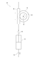
- FIG. 3 is a diagram showing a schematic configuration of the conversion unit according to the embodiment.
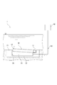
- FIG. 4 is a diagram for explaining a state where the door body swings upward in the swing energy conversion device.
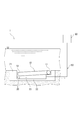
- FIG. 5 is a figure for demonstrating the state in which the door was swayed downwards in the motion energy converter.
- the vibration energy conversion device 1 of the present embodiment converts the vibration energy of a vibration body that is shaken by waves into power.
- the vibration energy conversion device 1 includes a door body 10, a storage unit 20, a mooring mechanism 30, an inflow / outflow passage 50, and a conversion unit 60. Note that a part of the mooring mechanism 30 is omitted in FIG. 1.
- the door body 10 is installed in the sea and constitutes a shaking body that is shaken by the waves.
- the door body 10 is a door body of an undulating gate type breakwater installed in a port as a measure against a tsunami or a high tide.
- the door body 10 is formed in a slightly flat and substantially rectangular shape, and has a rotating shaft 11 on the base end side.
- the door body 10 is provided in the storage section 20 so as to be rotatable around a rotation shaft 11.
- the door body 10 is rotated about the rotation axis 11 by the buoyancy from the lying state to stand up (float).
- the door body 10 stands up to prevent water from entering the port from outside.
- the door body 10 is moored in a laid-down state by the mooring mechanism 30.
- the door body 10 is configured such that the tip end portion 12 (tip end side) swings up and down due to waves in the laid state.
- the storage unit 20 is partitioned in the sea, the door body 10 constitutes a part of a partition wall, and a volume variation unit that allows water (seawater, the same applies hereinafter) to flow in and out due to an increase or decrease in the internal volume due to the shaking of the door body 10. Is composed of.
- the storage unit 20 is provided on the seabed, and the door body 10 is stored in a lying state.
- the storage unit 20 is formed in a substantially rectangular shape, and the door 10 constitutes an upper wall as a partition wall of the storage unit 20.
- the internal space 23 of the storage unit 20 thus formed is a semi-enclosed space.
- the internal space 23 is formed below the door body 10, that is, between the bottom wall 22 which is a partition wall of the storage section 20 and the door body 10.
- a gap is provided between the vertical wall 21 that is a partition wall of the storage unit 20 and the tip 12 of the door 10.
- the interior space 23 is filled with water.
- the tip end 12 of the door body 10 swings up and down (the tip end 12 of the door body 10 rotates about the rotation shaft 11), whereby the volume of the internal space 23 (hereinafter referred to as the internal volume). It also increases or decreases.
- the storage unit 20 is configured so that the water in the internal space 23 flows into and out of the inflow / outflow passage 50, which will be described later, by increasing or decreasing the internal volume.
- the mooring mechanism 30 allows the swinging of the door body 10 while applying a mooring force against the buoyancy of the door body 10 to the door body 10 to moor the door body 10 in a lying state.
- the mooring mechanism 30 has a hook 31, three rods 34, 35, 36, two turning link members 37, 38, a wire member 39, and a spring mechanism 43.
- the hook 31 has a shaft 32 at the base end, is rotatably provided around the shaft 32, and engages with the moored portion 13 of the door body 10 at the tip end side.
- a counterweight 33 that rotates the hook 31 is provided on the side where the engagement with the moored portion 13 is released (counterclockwise in FIG. 2).
- the hook 31 is provided with a pin 31a near the base end portion, and the vertical rod 34, the turning link member 37, the horizontal rod 35, the turning link member 38, the vertical rod 36, and the wire member 39 are sequentially connected to the pin 31a.
- the turning link members 37 and 38 are formed in a bell crank shape.
- the wire member 39 is wound around a pulley 42 (moving pulley) and connected to the spring mechanism 43.
- the pulley 42 is attached to the tip of the piston rod 41a of the cylinder 41, and is vertically movable by the forward / backward movement of the piston rod 41a.
- the mooring force of the hook 31 is increased via the rods 34, 35, 36 and the turning link members 37, 38. Loosen. Then, the hook 31 is pushed up by the buoyancy of the door 10 and the load of the counterweight 33, and the engagement with the moored portion 13 is released. As a result, the door body 10 stands up (flies) by buoyancy.
- the swinging of the door body 10 caused by waves is allowed by the expansion and contraction action of the spring mechanism 43 within a range where the engagement with the door body 10 is not released.
- the spring mechanism 43 extends and the swing of the door body 10 is allowed.
- the rods 34, 35, 36, the wire member 39, and the like are displaced in the direction indicated by the dashed arrow in FIG. In this case, the spring mechanism 43 contracts, and the swing of the door body 10 is allowed.
- the inflow / outflow passage 50 is a passage that is connected to the storage unit 20 and through which water flows in and out of the storage unit 20.
- One end of the inflow / outflow passage 50 is connected to the storage section 20 and communicates with the internal space 23.
- the other end of the inflow / outflow passage 50 is connected to the conversion unit 60.
- the tip end portion 12 of the door body 10 swings upward, so that the internal space 23 increases and becomes a negative pressure, so that water flows in from the inflow / outflow passage 50 ( Is aspirated). Further, as shown in FIG. 5, in the storage unit 20, the inner space 23 is compressed (decreased) and the pressure rises when the front end portion 12 of the door body 10 swings downward, so that water flows out. It flows out (is discharged) into the inlet passage 50.
- the mooring mechanism 30 is omitted in FIGS. 4 and 5.
- the amount of water flowing in and out (moving) is about 8.7 m 3 .
- Such a large amount of water flows through the inflow / outflow passage 50.
- the conversion unit 60 converts energy (fluid energy) of water flowing in and out of the storage unit 20 into motive power. As shown in FIG. 3, the conversion unit 60 includes a cylinder 61, a rack 63, a pinion 64, and a generator 66.
- the cylinder 61 is an actuator that is connected to the inflow / outflow passage 50 and is driven by water flowing in / out from the inflow / outflow passage 50. That is, in the cylinder 61, when water flows in from the inflow / outflow passage 50, the piston rod 62 advances (that is, moves upward in FIG. 3). Further, in the cylinder 61, when water flows out into the inflow / outflow passage 50, the piston rod 62 moves backward (that is, is displaced downward in FIG. 3).
- the cylinder 61 converts the energy of water flowing in and out of the inflow / outflow passage 50 into a linear reciprocating motion.
- the piston rod 62 of the cylinder 61 is connected to the rack 63.
- the rack 63 and the pinion 64 are power transmission mechanisms that mesh with each other.
- the rack 63 makes a linear reciprocating motion by the reciprocating motion of the piston rod 62.
- the pinion 64 performs a bidirectional rotational movement by the reciprocating movement of the rack 63. That is, the pinion 64 alternately repeats forward rotation and reverse rotation.
- the generator 66 has a drive shaft 65 connected to the pinion 64.
- the generator 66 is driven by the rotation of the pinion 64 to generate electricity.
- the generator 66 generates electric power when the pinion 64 rotates in both directions.
- the energy (fluid energy) of water flowing in and out of the storage unit 20 is converted into the power of the generator 66. That is, in the vibration energy converter 1, the vibration energy of the door 10 is converted into the power of the generator 66.
- the vibration energy conversion device 1 of the above-described embodiment includes the vibration body (door 10), the volume variation unit (storage unit 20), and the conversion unit 60.
- the swaying body is provided under the sea and is agitated by waves.
- the volume fluctuation section is partitioned in the sea, and the oscillating body constitutes a part of the partition wall, and water flows in and out according to an increase or decrease in the internal volume due to the sway of the oscillating body.
- the conversion unit 60 converts the energy of water flowing in and out of the volume changing unit into power.
- the volume changing section (storage section 20) is formed in a substantially rectangular shape, and the oscillating body constitutes an upper wall as the partition wall.
- the oscillating body (door body 10) is rotatably provided around a rotating shaft 11 provided on the base end side, and the tip end side is oscillated up and down due to waves.
- the vertical load due to waves effectively acts on the swaying body. Therefore, the wobbling motion of the wobbling body can be effectively generated.
- the swaying body is the door body 10 of the undulating gate type breakwater that is rotated about the rotation axis 11 by buoyancy from the laid state and stands upright. Is configured to. According to this configuration, it is possible to generate power by utilizing the laid door body 10 of the undulating gate type breakwater, that is, the unused door body 10.
- the vibration energy conversion device 1 of the above-described embodiment includes the mooring mechanism 30 that moors the door body 10 while allowing the vibration of the door body 10 to act and exerts a mooring force against the buoyancy of the door body 10. ing.
- the shaking energy of the door body 10 is converted into power, so that the shaking of the door body 10 is suppressed. That is, since the conversion into power becomes a resistance to the swaying operation of the door body 10, the door body 10 is less likely to sway. Therefore, the load on the mooring mechanism 30 can be reduced, and the design condition (design load) of the mooring mechanism 30 can be relaxed.
- the vibration energy conversion device 1 of the above-described embodiment is provided with the inflow / outflow passage 50 which is connected to the volume changing section (storage section 20) and through which water flows in and out of the volume changing section.
- the conversion unit 60 has an actuator (cylinder 61) that is connected to the inflow / outflow passage 50 and is driven by water flowing in / out from the inflow / outflow passage 50. According to this configuration, the energy of water can be converted into power with a simple configuration.
- the conversion unit 60 also has a generator 66 driven by an actuator (cylinder 61). With this configuration, it is possible to generate electric power using the vibration energy.
- the cylinder 61 is used as the actuator of the conversion unit 60, but a rotary machine such as a water wheel that converts the energy of water flowing in and out of the inflow / outflow passage 50 into a rotary motion may be used. ..
- the power may be used to drive a device other than the generator 66, such as a pump.
- the conversion unit 60 may use a power transmission mechanism other than the rack 63 and the pinion 64.
- passage diameter and the number of the inflow / outflow passages 50 can be appropriately changed according to the required amount of power generation and the amount of suppression of shaking of the door body 10.
- the technology disclosed in the present application is useful for a vibration energy conversion device.
- Vibration energy conversion device 10 Door body (motion body) 11 rotating shaft 12 tip (tip side) 20 Storage part (volume change part) 30 mooring mechanism 50 inflow / outflow passage 60 converter 61 cylinder (actuator) 66 generator
Landscapes
- Engineering & Computer Science (AREA)
- Chemical & Material Sciences (AREA)
- Combustion & Propulsion (AREA)
- Mechanical Engineering (AREA)
- General Engineering & Computer Science (AREA)
- Other Liquid Machine Or Engine Such As Wave Power Use (AREA)
- Revetment (AREA)
Abstract
動揺エネルギー変換装置1は、海中に設けられ、波浪によって動揺する扉体10(動揺体)と、海中において区画されると共に扉体10が区画壁の一部を構成し、扉体10の動揺による内部容積の増減によって水を流出入させる格納部20(容積変動部)と、格納部20から流出入した水のエネルギーを動力に変換する変換部60とを備えている。
Description
本願は、動揺エネルギー変換装置に関する。
津波や高潮などの対策として港湾に設置される起伏ゲート式防波堤が、例えば特許文献1に開示されている。この防波堤は、浮力によって起立(浮上)する扉体と、該扉体を倒伏状態で係留する係留機構とを備えている。倒伏状態の扉体は、波浪による荷重が作用するため動揺する。ここで、扉体を動揺させないように係留機構によって完全に固定した場合、係留機構には比較的大きな荷重が繰り返し作用してしまう。そのため、特許文献1の係留機構は、波浪による扉体の動揺を許容しつつ係留している。
ところで、上述したような起伏ゲート式防波堤では、波浪によって生じる扉体の動揺エネルギーが有効活用されていない。
本願に開示の技術は、かかる事情に鑑みてなされたものであり、その目的は、波浪によって生じる物体の動揺エネルギーを有効活用することにある。
本願の動揺エネルギー変換装置は、動揺体と、容積変動部と、変換部とを備えている。前記動揺体は、海中に設けられ、波浪によって動揺するものである。前記容積変動部は、海中において区画されると共に前記動揺体が区画壁の一部を構成し、前記動揺体の動揺による内部容積の増減によって水を流出入させるものである。前記変換部は、前記容積変動部から流出入した水のエネルギーを動力に変換するものである。なお、上記の「区画される」は、当然ながら、二次元平面だけでなく三次元空間も含む。
本願の動揺エネルギー変換装置によれば、波浪によって生じる物体の動揺エネルギーを有効活用することができる。
以下、本願の実施形態について図面を参照しながら説明する。なお、以下の実施形態は、本質的に好ましい例示であって、本願に開示の技術、その適用物、あるいはその用途の範囲を制限することを意図するものではない。
図1および図2に示すように、本実施形態の動揺エネルギー変換装置1は、波浪によって動揺する動揺体の動揺エネルギーを動力に変換するものである。動揺エネルギー変換装置1は、扉体10と、格納部20と、係留機構30と、流出入通路50と、変換部60とを備えている。なお、図1では、係留機構30の一部を省略している。
扉体10は、海中に設けられ、波浪によって動揺する動揺体を構成している。扉体10は、津波や高潮などの対策として港湾に設置される起伏ゲート式防波堤の扉体である。扉体10は、やや扁平な略矩形体状に形成され、基端側に回動軸11を有している。扉体10は、回動軸11を中心に回動自在に格納部20に設けられている。
扉体10は、倒伏状態から浮力によって回動軸11を中心に回動し起立(浮上)する。扉体10は、起立することにより、港外から港内へ水が浸入するのを防止する。扉体10は、係留機構30によって倒伏状態で係留されている。扉体10は、倒伏状態時に先端部12(先端側)が波浪によって上下に動揺するように構成されている。
格納部20は、海中において区画されると共に扉体10が区画壁の一部を構成し、扉体10の動揺による内部容積の増減によって水(海水、以下同様。)を流出入させる容積変動部を構成している。
具体的に、格納部20は、海底に設けられており、扉体10が倒伏状態で格納される。格納部20は、略矩形体状に形成されており、扉体10が、格納部20の区画壁としての上壁を構成している。こうして形成された格納部20の内部空間23は、半密閉空間となっている。
つまり、内部空間23は、扉体10の下方、即ち格納部20の区画壁である底壁22と扉体10との間に形成されている。格納部20の区画壁である縦壁21と、扉体10の先端部12との間には、隙間が設けられている。内部空間23には、水が充満している。なお、上記の隙間は、扉体10の動揺を許容するだけのできるだけ小さい隙間であることが望ましい。
格納部20では、扉体10の先端部12が上下に動揺する(扉体10の先端部12が回動軸11を中心に回動する)ことによって、内部空間23の容積(以下、内部容積とも言う。)が増減する。そして、格納部20は、内部容積が増減することによって、内部空間23の水が後述する流出入通路50に流出入するように構成されている。
係留機構30は、扉体10の動揺を許容しつつ、扉体10の浮力に抗する係留力を扉体10に作用させて倒伏状態の扉体10を係留するものである。係留機構30は、フック31と、3つのロッド34,35,36と、2つの転向リンク部材37,38と、ワイヤ部材39と、ばね機構43とを有している。
フック31は、基端部に軸32を有し、軸32を中心に回動自在に設けられ、先端側で扉体10の被係留部13に係合する。フック31の基端部には、被係留部13との係合を解除する側(図2において左回り)にフック31を回転させるカウンタウエイト33が設けられている。
フック31には、基端部寄りにピン31aが設けられており、該ピン31aに鉛直ロッド34、転向リンク部材37、水平ロッド35、転向リンク部材38、鉛直ロッド36およびワイヤ部材39が順に連結されている。転向リンク部材37,38は、ベルクランク状に形成されている。
ワイヤ部材39は、滑車42(動滑車)に巻き回されて、ばね機構43に接続されている。滑車42は、シリンダ41のピストンロッド41aの先端に取り付けられており、ピストンロッド41aの進退動作によって上下動自在となっている。
上記のように構成された係留機構30では、シリンダ41の圧力を開放して保持力を緩めることにより、ロッド34,35,36や転向リンク部材37,38を介して、フック31の係留力が緩まる。そうすると、扉体10の浮力およびカウンタウエイト33の荷重により、フック31は押し上げられ被係留部13との係合が解除される。これにより、扉体10は浮力によって起立(浮上)する。
また、係留機構30では、扉体10との係合が解除されない範囲で、波浪によって生じる扉体10の動揺を、ばね機構43の伸縮作用により許容している。例えば、波浪によって水位が低下し、扉体10が上方へ動揺した場合、ロッド34,35,36やワイヤ部材39等は、図2に実線の矢印で示す方向に変位する。この場合、ばね機構43は伸びて、扉体10の動揺が許容される。また、波浪によって水位が上昇し、扉体10が下方へ動揺した場合、ロッド34,35,36やワイヤ部材39等は、図2に破線の矢印で示す方向に変位する。この場合、ばね機構43は縮んで、扉体10の動揺が許容される。
流出入通路50は、格納部20に接続され、格納部20から水が流出入する通路である。流出入通路50の一端は、格納部20に接続され、内部空間23に連通している。流出入通路50の他端は、変換部60に接続されている。
図4に示すように、格納部20では、扉体10の先端部12が上方へ動揺することで、内部空間23は増大して負圧となるため、流出入通路50から水が流入する(吸引される)。また、図5に示すように、格納部20では、扉体10の先端部12が下方へ動揺することで、内部空間23は圧縮されて(減少して)圧力が上昇するため、水が流出入通路50に流出する(吐出される)。なお、図4および図5では、係留機構30を省略している。
例えば、扉体10の大きさを幅10m×長さ10m、扉体10の動揺振幅を±0.5°とした場合、流出入(移動)する水量は約8.7m3となる。このような大流量の水が流出入通路50を流れる。
変換部60は、格納部20から流出入した水のエネルギー(流体エネルギー)を動力に変換する。図3に示すように、変換部60は、シリンダ61と、ラック63およびピニオン64と、発電機66とを有している。
シリンダ61は、流出入通路50に接続され、流出入通路50から水が流出入することによって駆動されるアクチュエータである。つまり、シリンダ61は、流出入通路50から水が流入した場合、ピストンロッド62が進出(即ち、図3において上へ変位)する。また、シリンダ61は、流出入通路50へ水が流出した場合、ピストンロッド62が後退(即ち、図3において下へ変位)する。
このように、シリンダ61は、流出入通路50から流出入する水のエネルギーを、直線的な往復運動に変換する。シリンダ61のピストンロッド62は、ラック63に接続されている。
ラック63およびピニオン64は、互いに噛み合う動力伝達機構である。ラック63は、ピストンロッド62の往復運動によって直線的な往復運動を行う。ピニオン64は、ラック63の往復運動によって、双方向の回転運動を行う。つまり、ピニオン64は、正回転と逆回転とを交互に繰り返す。
発電機66は、駆動軸65がピニオン64に連結されている。発電機66は、ピニオン64の回転によって駆動され発電を行う。なお、発電機66は、ピニオン64の双方向の何れの回転時にも発電を行う。
こうして、変換部60では、格納部20から流出入した水のエネルギー(流体エネルギー)が、発電機66の動力に変換される。つまり、動揺エネルギー変換装置1では、扉体10の動揺エネルギーが、発電機66の動力に変換される。
以上のように、上記実施形態の動揺エネルギー変換装置1は、動揺体(扉体10)と、容積変動部(格納部20)と、変換部60とを備えている。動揺体は、海中に設けられ、波浪によって動揺する。容積変動部は、海中において区画されると共に動揺体が区画壁の一部を構成し、動揺体の動揺による内部容積の増減によって水を流出入させる。変換部60は、容積変動部から流出入した水のエネルギーを動力に変換する。
上記の構成によれば、動揺体の動揺動作を水(海水)のエネルギーに変換し、その水のエネルギーを動力に変換することができる。そのため、波浪によって生じる物体の動揺エネルギーを有効活用することができる。
また、容積変動部(格納部20)は、略矩形体状に形成され、前記動揺体が、前記区画壁としての上壁を構成している。動揺体(扉体10)は、基端側に設けられた回動軸11を中心として回動自在に設けられ、先端側が波浪によって上下に動揺するように構成されている。
上記の構成によれば、波浪による鉛直方向の荷重が動揺体に効果的に作用する。そのため、動揺体の動揺動作を効果的に生じさせることができる。
また、動揺体は、倒伏状態から浮力によって回動軸11を中心に回動し起立する起伏ゲート式防波堤の扉体10であり、倒伏状態時に先端側(先端部12)が波浪によって上下に動揺するように構成されている。この構成によれば、起伏ゲート式防波堤の倒伏している扉体10、即ち未使用時の扉体10を利用して、動力を発生させることができる。
また、上記実施形態の動揺エネルギー変換装置1は、扉体10の動揺を許容しつつ扉体10の浮力に抗する係留力を作用させて倒伏状態の扉体10を係留する係留機構30を備えている。この構成によれば、扉体10の動揺エネルギーが動力に変換されることから、扉体10の動揺が抑制される。つまり、動力への変換が扉体10の動揺動作の抵抗となるため、扉体10は動揺し難くなる。そのため、係留機構30の負荷を軽減することができ、係留機構30の設計条件(設計荷重)を緩和することができる。
また、上記実施形態の動揺エネルギー変換装置1は、容積変動部(格納部20)に接続され、容積変動部から水が流出入する流出入通路50を備えている。そして、変換部60は、流出入通路50に接続され、流出入通路50から水が流出入することによって駆動されるアクチュエータ(シリンダ61)を有している。この構成によれば、簡易な構成で、水のエネルギーを動力に変換することができる。
また、変換部60は、アクチュエータ(シリンダ61)によって駆動される発電機66を有している。この構成により、動揺エネルギーを利用して発電することができる。
なお、本願に開示の技術は、上記実施形態において以下のとおり構成するようにしてもよい。
例えば、上記実施形態では、変換部60のアクチュエータとしてシリンダ61を用いたが、流出入通路50から流出入する水のエネルギーを、回転運動に変換する水車等の回転機械を用いるようにしてもよい。
また、変換部60では、動力を発電機66以外の例えばポンプ等の機器の駆動に用いるようにしてもよい。
また、変換部60では、ラック63およびピニオン64以外の動力伝達機構を用いてもよいことは勿論である。
また、流出入通路50の通路径および本数は、必要な発電量や扉体10の動揺の抑制量に応じて適宜変更可能である。
以上のように、本願に開示の技術は、動揺エネルギー変換装置について有用である。
1 動揺エネルギー変換装置
10 扉体(動揺体)
11 回動軸
12 先端部(先端側)
20 格納部(容積変動部)
30 係留機構
50 流出入通路
60 変換部
61 シリンダ(アクチュエータ)
66 発電機
10 扉体(動揺体)
11 回動軸
12 先端部(先端側)
20 格納部(容積変動部)
30 係留機構
50 流出入通路
60 変換部
61 シリンダ(アクチュエータ)
66 発電機
Claims (6)
- 海中に設けられ、波浪によって動揺する動揺体と、
海中において区画されると共に前記動揺体が区画壁の一部を構成し、前記動揺体の動揺による内部容積の増減によって水を流出入させる容積変動部と、
前記容積変動部から流出入した水のエネルギーを動力に変換する変換部とを備えている
ことを特徴とする動揺エネルギー変換装置。 - 請求項1に記載の動揺エネルギー変換装置において、
前記容積変動部は、略矩形体状に形成され、前記動揺体が、前記区画壁としての上壁を構成しており、
前記動揺体は、基端側に設けられた回動軸を中心として回動自在に設けられ、先端側が波浪によって上下に動揺するように構成されている
ことを特徴とする動揺エネルギー変換装置。 - 請求項2に記載の動揺エネルギー変換装置において、
前記動揺体は、倒伏状態から浮力によって前記回動軸を中心に回動し起立する起伏ゲート式防波堤の扉体であり、倒伏状態時に先端側が波浪によって上下に動揺するように構成されている
ことを特徴とする動揺エネルギー変換装置。 - 請求項3に記載の動揺エネルギー変換装置において、
前記扉体の動揺を許容しつつ前記扉体の浮力に抗する係留力を作用させて倒伏状態の前記扉体を係留する係留機構を備えている
ことを特徴とする動揺エネルギー変換装置。 - 請求項1乃至4の何れか1項に記載の動揺エネルギー変換装置において、
前記容積変動部に接続され、該容積変動部から水が流出入する流出入通路を備え、
前記変換部は、前記流出入通路に接続され、該流出入通路から水が流出入することによって駆動されるアクチュエータを有している
ことを特徴とする動揺エネルギー変換装置。 - 請求項5に記載の動揺エネルギー変換装置において、
前記変換部は、前記アクチュエータによって駆動される発電機を有している
ことを特徴とする動揺エネルギー変換装置。
Applications Claiming Priority (2)
| Application Number | Priority Date | Filing Date | Title |
|---|---|---|---|
| JP2018204249A JP6962896B2 (ja) | 2018-10-30 | 2018-10-30 | 動揺エネルギー変換装置 |
| JP2018-204249 | 2018-10-30 |
Publications (1)
| Publication Number | Publication Date |
|---|---|
| WO2020090490A1 true WO2020090490A1 (ja) | 2020-05-07 |
Family
ID=70464077
Family Applications (1)
| Application Number | Title | Priority Date | Filing Date |
|---|---|---|---|
| PCT/JP2019/040842 Ceased WO2020090490A1 (ja) | 2018-10-30 | 2019-10-17 | 動揺エネルギー変換装置 |
Country Status (3)
| Country | Link |
|---|---|
| JP (1) | JP6962896B2 (ja) |
| TW (1) | TW202020267A (ja) |
| WO (1) | WO2020090490A1 (ja) |
Citations (6)
| Publication number | Priority date | Publication date | Assignee | Title |
|---|---|---|---|---|
| JPS5692367A (en) * | 1979-12-26 | 1981-07-27 | Hitachi Zosen Corp | Wave energy conversion device |
| JPS56110573A (en) * | 1980-02-05 | 1981-09-01 | Shii Enajii Asooshieitsu Ltd | Floating device |
| JPS5870067A (ja) * | 1981-10-22 | 1983-04-26 | Yoshizo Morita | 波力発電 |
| JPS5943987A (ja) * | 1982-09-03 | 1984-03-12 | Hitachi Zosen Corp | 波力エネルギ−吸収装置 |
| JP2002303242A (ja) * | 2001-04-09 | 2002-10-18 | Yuji Mochizuki | 波力発電装置 |
| JP2014513242A (ja) * | 2011-05-04 | 2014-05-29 | ザイバ リニューアブルス リミテッド | 波エネルギー抽出装置及び方法 |
Family Cites Families (2)
| Publication number | Priority date | Publication date | Assignee | Title |
|---|---|---|---|---|
| JP5250534B2 (ja) * | 2009-11-25 | 2013-07-31 | 日立造船株式会社 | 起伏ゲート式防波堤における係留機構の弾性係数決定方法 |
| US8866328B1 (en) * | 2011-06-07 | 2014-10-21 | Leidos, Inc. | System and method for generated power from wave action |
-
2018
- 2018-10-30 JP JP2018204249A patent/JP6962896B2/ja active Active
-
2019
- 2019-10-15 TW TW108137068A patent/TW202020267A/zh unknown
- 2019-10-17 WO PCT/JP2019/040842 patent/WO2020090490A1/ja not_active Ceased
Patent Citations (6)
| Publication number | Priority date | Publication date | Assignee | Title |
|---|---|---|---|---|
| JPS5692367A (en) * | 1979-12-26 | 1981-07-27 | Hitachi Zosen Corp | Wave energy conversion device |
| JPS56110573A (en) * | 1980-02-05 | 1981-09-01 | Shii Enajii Asooshieitsu Ltd | Floating device |
| JPS5870067A (ja) * | 1981-10-22 | 1983-04-26 | Yoshizo Morita | 波力発電 |
| JPS5943987A (ja) * | 1982-09-03 | 1984-03-12 | Hitachi Zosen Corp | 波力エネルギ−吸収装置 |
| JP2002303242A (ja) * | 2001-04-09 | 2002-10-18 | Yuji Mochizuki | 波力発電装置 |
| JP2014513242A (ja) * | 2011-05-04 | 2014-05-29 | ザイバ リニューアブルス リミテッド | 波エネルギー抽出装置及び方法 |
Also Published As
| Publication number | Publication date |
|---|---|
| JP6962896B2 (ja) | 2021-11-05 |
| TW202020267A (zh) | 2020-06-01 |
| JP2020070744A (ja) | 2020-05-07 |
Similar Documents
| Publication | Publication Date | Title |
|---|---|---|
| US9309860B2 (en) | Wave energy conversion device | |
| US8004103B2 (en) | Power generation | |
| Vicente et al. | Nonlinear dynamics of a tightly moored point-absorber wave energy converter | |
| JP4831921B2 (ja) | ポテンシャルエネルギを貯蔵する装置 | |
| CN110469448A (zh) | 一种浮力摆机构及振荡水柱式波浪能发电装置 | |
| CN107288807A (zh) | 具有振荡抑制板的多浮筏波浪能发电装置 | |
| KR101392282B1 (ko) | 파력 발전장치 | |
| CN110439734A (zh) | 一种具有偏置惯性体的振荡浮子波浪能发电装置 | |
| CN111532382A (zh) | 内部惯性体式波浪能供电海洋监测浮标 | |
| CN114555933B (zh) | 驱动组件 | |
| KR101777519B1 (ko) | 파력 발전 장치 | |
| CN114233561A (zh) | 基于张力腿式系泊的多自由度波浪能利用装置 | |
| CN119373643A (zh) | 一种波浪能发电装置 | |
| CN104005902B (zh) | 多维并联摆动海浪发电装置 | |
| JP4201262B2 (ja) | 液面上の浮きの上下動により回転運動として取り出すことを特徴とするエネルギー変換方法。 | |
| JP2010133394A (ja) | 波力発電装置 | |
| RU49135U1 (ru) | Волновая электростанция | |
| JP2012518752A (ja) | 電力捕捉装置 | |
| KR100886837B1 (ko) | 파도력 발전장치 | |
| WO2020090490A1 (ja) | 動揺エネルギー変換装置 | |
| CN210531047U (zh) | 一种具有偏置惯性体的振荡浮子波浪能发电装置 | |
| JP2020070595A (ja) | 起伏ゲート式防波堤 | |
| CN103291553A (zh) | 带谐和吸收装置的浮式双叶风电机 | |
| KR101492768B1 (ko) | 횡류터빈을 이용한 부유식 파력발전장치 | |
| JP2018028275A (ja) | 発電機用駆動装置 |
Legal Events
| Date | Code | Title | Description |
|---|---|---|---|
| 121 | Ep: the epo has been informed by wipo that ep was designated in this application |
Ref document number: 19879265 Country of ref document: EP Kind code of ref document: A1 |
|
| NENP | Non-entry into the national phase |
Ref country code: DE |
|
| 122 | Ep: pct application non-entry in european phase |
Ref document number: 19879265 Country of ref document: EP Kind code of ref document: A1 |