WO2020090302A1 - 高強度部材、高強度部材の製造方法及び高強度部材用鋼板の製造方法 - Google Patents
高強度部材、高強度部材の製造方法及び高強度部材用鋼板の製造方法 Download PDFInfo
- Publication number
- WO2020090302A1 WO2020090302A1 PCT/JP2019/037688 JP2019037688W WO2020090302A1 WO 2020090302 A1 WO2020090302 A1 WO 2020090302A1 JP 2019037688 W JP2019037688 W JP 2019037688W WO 2020090302 A1 WO2020090302 A1 WO 2020090302A1
- Authority
- WO
- WIPO (PCT)
- Prior art keywords
- less
- steel sheet
- strength member
- strength
- bending
- Prior art date
Links
Images

Classifications
-
- C—CHEMISTRY; METALLURGY
- C22—METALLURGY; FERROUS OR NON-FERROUS ALLOYS; TREATMENT OF ALLOYS OR NON-FERROUS METALS
- C22C—ALLOYS
- C22C38/00—Ferrous alloys, e.g. steel alloys
- C22C38/001—Ferrous alloys, e.g. steel alloys containing N
-
- C—CHEMISTRY; METALLURGY
- C22—METALLURGY; FERROUS OR NON-FERROUS ALLOYS; TREATMENT OF ALLOYS OR NON-FERROUS METALS
- C22C—ALLOYS
- C22C38/00—Ferrous alloys, e.g. steel alloys
- C22C38/02—Ferrous alloys, e.g. steel alloys containing silicon
-
- C—CHEMISTRY; METALLURGY
- C21—METALLURGY OF IRON
- C21D—MODIFYING THE PHYSICAL STRUCTURE OF FERROUS METALS; GENERAL DEVICES FOR HEAT TREATMENT OF FERROUS OR NON-FERROUS METALS OR ALLOYS; MAKING METAL MALLEABLE, e.g. BY DECARBURISATION OR TEMPERING
- C21D8/00—Modifying the physical properties by deformation combined with, or followed by, heat treatment
- C21D8/02—Modifying the physical properties by deformation combined with, or followed by, heat treatment during manufacturing of plates or strips
- C21D8/0221—Modifying the physical properties by deformation combined with, or followed by, heat treatment during manufacturing of plates or strips characterised by the working steps
- C21D8/0226—Hot rolling
-
- C—CHEMISTRY; METALLURGY
- C21—METALLURGY OF IRON
- C21D—MODIFYING THE PHYSICAL STRUCTURE OF FERROUS METALS; GENERAL DEVICES FOR HEAT TREATMENT OF FERROUS OR NON-FERROUS METALS OR ALLOYS; MAKING METAL MALLEABLE, e.g. BY DECARBURISATION OR TEMPERING
- C21D8/00—Modifying the physical properties by deformation combined with, or followed by, heat treatment
- C21D8/02—Modifying the physical properties by deformation combined with, or followed by, heat treatment during manufacturing of plates or strips
- C21D8/0221—Modifying the physical properties by deformation combined with, or followed by, heat treatment during manufacturing of plates or strips characterised by the working steps
- C21D8/0236—Cold rolling
-
- C—CHEMISTRY; METALLURGY
- C21—METALLURGY OF IRON
- C21D—MODIFYING THE PHYSICAL STRUCTURE OF FERROUS METALS; GENERAL DEVICES FOR HEAT TREATMENT OF FERROUS OR NON-FERROUS METALS OR ALLOYS; MAKING METAL MALLEABLE, e.g. BY DECARBURISATION OR TEMPERING
- C21D8/00—Modifying the physical properties by deformation combined with, or followed by, heat treatment
- C21D8/02—Modifying the physical properties by deformation combined with, or followed by, heat treatment during manufacturing of plates or strips
- C21D8/0247—Modifying the physical properties by deformation combined with, or followed by, heat treatment during manufacturing of plates or strips characterised by the heat treatment
- C21D8/0273—Final recrystallisation annealing
-
- C—CHEMISTRY; METALLURGY
- C21—METALLURGY OF IRON
- C21D—MODIFYING THE PHYSICAL STRUCTURE OF FERROUS METALS; GENERAL DEVICES FOR HEAT TREATMENT OF FERROUS OR NON-FERROUS METALS OR ALLOYS; MAKING METAL MALLEABLE, e.g. BY DECARBURISATION OR TEMPERING
- C21D9/00—Heat treatment, e.g. annealing, hardening, quenching or tempering, adapted for particular articles; Furnaces therefor
- C21D9/46—Heat treatment, e.g. annealing, hardening, quenching or tempering, adapted for particular articles; Furnaces therefor for sheet metals
-
- C—CHEMISTRY; METALLURGY
- C22—METALLURGY; FERROUS OR NON-FERROUS ALLOYS; TREATMENT OF ALLOYS OR NON-FERROUS METALS
- C22C—ALLOYS
- C22C38/00—Ferrous alloys, e.g. steel alloys
- C22C38/04—Ferrous alloys, e.g. steel alloys containing manganese
-
- C—CHEMISTRY; METALLURGY
- C22—METALLURGY; FERROUS OR NON-FERROUS ALLOYS; TREATMENT OF ALLOYS OR NON-FERROUS METALS
- C22C—ALLOYS
- C22C38/00—Ferrous alloys, e.g. steel alloys
- C22C38/06—Ferrous alloys, e.g. steel alloys containing aluminium
-
- C—CHEMISTRY; METALLURGY
- C22—METALLURGY; FERROUS OR NON-FERROUS ALLOYS; TREATMENT OF ALLOYS OR NON-FERROUS METALS
- C22C—ALLOYS
- C22C38/00—Ferrous alloys, e.g. steel alloys
- C22C38/08—Ferrous alloys, e.g. steel alloys containing nickel
-
- C—CHEMISTRY; METALLURGY
- C22—METALLURGY; FERROUS OR NON-FERROUS ALLOYS; TREATMENT OF ALLOYS OR NON-FERROUS METALS
- C22C—ALLOYS
- C22C38/00—Ferrous alloys, e.g. steel alloys
- C22C38/12—Ferrous alloys, e.g. steel alloys containing tungsten, tantalum, molybdenum, vanadium, or niobium
-
- C—CHEMISTRY; METALLURGY
- C22—METALLURGY; FERROUS OR NON-FERROUS ALLOYS; TREATMENT OF ALLOYS OR NON-FERROUS METALS
- C22C—ALLOYS
- C22C38/00—Ferrous alloys, e.g. steel alloys
- C22C38/14—Ferrous alloys, e.g. steel alloys containing titanium or zirconium
-
- C—CHEMISTRY; METALLURGY
- C22—METALLURGY; FERROUS OR NON-FERROUS ALLOYS; TREATMENT OF ALLOYS OR NON-FERROUS METALS
- C22C—ALLOYS
- C22C38/00—Ferrous alloys, e.g. steel alloys
- C22C38/16—Ferrous alloys, e.g. steel alloys containing copper
-
- C—CHEMISTRY; METALLURGY
- C22—METALLURGY; FERROUS OR NON-FERROUS ALLOYS; TREATMENT OF ALLOYS OR NON-FERROUS METALS
- C22C—ALLOYS
- C22C38/00—Ferrous alloys, e.g. steel alloys
- C22C38/60—Ferrous alloys, e.g. steel alloys containing lead, selenium, tellurium, or antimony, or more than 0.04% by weight of sulfur
-
- C—CHEMISTRY; METALLURGY
- C21—METALLURGY OF IRON
- C21D—MODIFYING THE PHYSICAL STRUCTURE OF FERROUS METALS; GENERAL DEVICES FOR HEAT TREATMENT OF FERROUS OR NON-FERROUS METALS OR ALLOYS; MAKING METAL MALLEABLE, e.g. BY DECARBURISATION OR TEMPERING
- C21D2211/00—Microstructure comprising significant phases
- C21D2211/002—Bainite
-
- C—CHEMISTRY; METALLURGY
- C21—METALLURGY OF IRON
- C21D—MODIFYING THE PHYSICAL STRUCTURE OF FERROUS METALS; GENERAL DEVICES FOR HEAT TREATMENT OF FERROUS OR NON-FERROUS METALS OR ALLOYS; MAKING METAL MALLEABLE, e.g. BY DECARBURISATION OR TEMPERING
- C21D2211/00—Microstructure comprising significant phases
- C21D2211/003—Cementite
-
- C—CHEMISTRY; METALLURGY
- C21—METALLURGY OF IRON
- C21D—MODIFYING THE PHYSICAL STRUCTURE OF FERROUS METALS; GENERAL DEVICES FOR HEAT TREATMENT OF FERROUS OR NON-FERROUS METALS OR ALLOYS; MAKING METAL MALLEABLE, e.g. BY DECARBURISATION OR TEMPERING
- C21D2211/00—Microstructure comprising significant phases
- C21D2211/008—Martensite
Definitions
- the present invention relates to a high-strength member used for automobile parts and the like, a method for manufacturing a high-strength member, and a method for manufacturing a steel plate for a high-strength member. More specifically, the present invention relates to a high-strength member excellent in delayed fracture resistance and a method for manufacturing the same. The present invention also relates to a method for manufacturing a steel plate for the high strength member.
- TS tensile strength
- delayed fracture With the increase in strength of steel sheets, there is a concern that delayed fracture may occur, and in recent years, there has been concern about delayed fracture from the sheared end face of the sample processed into the shape of the part, especially the bending portion where strain is concentrated. It is important to suppress delayed fracture starting from a sheared end face.
- the chemical components are C: 0.05 to 0.3%, Si: 3.0% or less, Mn: 0.01 to 3.0%, P: 0.02% or less, and S: : 0.02% or less, Al: 3.0% or less, N: 0.01% or less, the balance being Fe and inevitable impurities made of steel, and oxides of Mg, sulfides, complex crystallized substances and
- Patent Document 2 provides a method for producing a molded member having excellent delayed fracture resistance by reducing residual stress on the end face by performing shot peening on the sheared end face of a steel sheet having a TS of 1180 MPa or more.
- Patent Document 1 provides a steel sheet having excellent delayed fracture resistance by defining the chemical composition and the grain size and density of precipitates in the steel.
- the steel sheet of Patent Document 1 has a small amount of added C, it has lower strength than the steel sheet used for the high-strength member of the present invention, and TS is less than 1470 MPa.
- TS is less than 1470 MPa.
- the strength is improved by increasing the amount of C or the like, when the strength is increased, the residual stress on the end face is also increased, and thus the delayed fracture resistance is considered to be deteriorated.
- Patent Document 2 provides a molded member that has shot peening on the sheared end face to reduce residual stress on the end face and has excellent delayed fracture resistance.
- delayed fracture occurs even at the residual stress of the end surface of 800 MPa or less specified in the present invention, which is considered to be because the crack length of the end surface is longer than the length specified in the present invention. Even if shot peening is applied, if the sheared end face is left, cracks caused by shearing exceed 10 ⁇ m, which is insufficient as an effect of improving delayed fracture resistance.
- the present invention has been made in view of the above circumstances, and an object thereof is to provide a high-strength member excellent in delayed fracture resistance, a method for manufacturing a high-strength member, and a method for manufacturing a steel plate for a high-strength member. It is to be.
- high strength means that the tensile strength (TS) is 1470 MPa or more.
- the term "excellent delayed fracture resistance” means that, as described in Examples, the member after bending the steel sheet is immersed in hydrochloric acid having a pH of 1 (25 ° C), and the maximum load stress that does not cause delayed fracture is obtained. Means that the critical load stress is equal to or higher than the yield strength (YS).
- a high-strength member having a bent ridge portion obtained by using a steel sheet has a tensile strength of 1470 MPa or more and an end surface of the bent ridge portion.
- the inventors have found that it can be done and have reached the present invention.
- the above problem can be solved by the following means.
- the steel sheet is mass%, C: 0.17% or more and 0.35% or less, Si: 0.001% or more and 1.2% or less, Mn: 0.9% or more and 3.2% or less, P: 0.02% or less, S: 0.001% or less, Al: 0.01% or more and 0.2% or less, and N: 0.010% or less, with the balance being a component composition consisting of Fe and inevitable impurities, With respect to the entire steel sheet structure, the area ratio of bainite containing carbide having an average particle size of 50 nm or less and martensite containing carbide having an average particle size of 50 nm or less is 90% or more in total.
- the high-strength member according to [1] which has a microstructure.
- the steel sheet is mass%, C: 0.17% or more and 0.35% or less, Si: 0.001% or more and 1.2% or less, Mn: 0.9% or more and 3.2% or less, P: 0.02% or less, S: 0.001% or less, Al: 0.01% or more and 0.2% or less, N: 0.010% or less, and Sb: 0.001% or more and 0.1% or less, with the balance being a component composition consisting of Fe and inevitable impurities, With respect to the entire steel sheet structure, the area ratio of bainite containing carbide having an average particle size of 50 nm or less and martensite containing carbide having an average particle size of 50 nm or less is 90% or more in total.
- the high-strength member according to [1] which has a microstructure.
- the component composition of the steel sheet is further mass%
- B The high-strength member according to [2] or [3], containing 0.0002% or more and less than 0.0035%.
- the component composition of the steel sheet is further mass%, Nb: 0.002% or more and 0.08% or less, and Ti: at least one selected from 0.002% or more and 0.12% or less, and any one of [2] to [4] The high-strength member described.
- the component composition of the steel sheet is further mass%, High strength according to any one of [2] to [5], containing at least one selected from Cu: 0.005% or more and 1% or less and Ni: 0.005% or more and 1% or less. Element.
- composition of the steel sheet is further in mass%, Cr: 0.01% or more and 1.0% or less, Mo: 0.01% or more and less than 0.3%, V: 0.003% or more and 0.5% or less, Any one of [2] to [6], containing at least one selected from Zr: 0.005% or more and 0.20% or less, and W: 0.005% or more and 0.20% or less.
- the component composition of the steel sheet is further in mass%, Ca: 0.0002% or more and 0.0030% or less, Ce: 0.0002% or more and 0.0030% or less, La: 0.0002% or more and 0.0030% or less, and Mg: at least one selected from 0.0002% or more and 0.0030% or less, any one of [2] to [7]
- the component composition of the steel sheet is further% by mass.
- Sn The high-strength member according to any one of [2] to [8], containing 0.002% or more and 0.1% or less.
- the end surface produced by cutting is chamfered before or after bending, and heated at a temperature of 270 ° C. or lower after the bending and the chamfering.
- a method for manufacturing a high-strength member having an end face treatment step is
- the end surface generated by cutting is chamfered before or after bending, and the bending and the chamfering are performed.
- a method for producing a high-strength member which comprises an end face treatment step of heating at a temperature of 270 ° C. or lower after the step.
- a method for manufacturing a high-strength member steel plate for manufacturing the high-strength member according to any one of [2] to [9], A step of performing hot rolling and cold rolling on the steel having the component composition; After heating the cold-rolled steel sheet obtained by the cold rolling to an annealing temperature of AC 3 points or higher, the average cooling rate in the temperature range from the annealing temperature to 550 ° C is set to 3 ° C / sec or higher, and the cooling stop temperature is set. To 350 ° C. or less, and then an annealing step of allowing the material to stay in a temperature range of 100 ° C. or more and 260 ° C. or less for 20 seconds or more and 1500 seconds or less.
- the present invention it is possible to provide a high-strength member excellent in delayed fracture resistance, a method for manufacturing a high-strength member, and a method for manufacturing a steel plate for a high-strength member. Further, by applying the high-strength member of the present invention to an automobile structural member, it is possible to achieve both high strength of the automobile steel sheet and improvement of delayed fracture resistance. That is, the present invention improves the performance of the automobile body.
- FIG. 5 is an enlarged view of the end face showing the measurement direction and the plate thickness center that is the measurement point in the measurement of the residual stress on the end face of the example.
- the high-strength member of the present invention is a high-strength member having a bending ridge portion obtained by using a steel plate, the tensile strength of the member is 1470 MPa or more, the residual stress of the end surface of the bending ridge portion is 800 MPa or less, Moreover, the longest crack length among the cracks extending from the end face of the bending ridgeline portion in the bending ridgeline direction is 10 ⁇ m or less.
- the steel sheet used for the high-strength member is not particularly limited as long as the high-strength member satisfying these conditions is obtained.
- a preferable steel plate for obtaining the high-strength member of the present invention will be described, but the steel plate used for the high-strength member of the present invention is not limited to the steel plate described below.
- a preferred steel sheet for obtaining a high-strength member preferably has a constituent structure described below and a microstructure.
- the high-strength member of the present invention it is not always necessary to use a steel plate having a component composition and a microstructure described later.
- C is an element that improves hardenability.
- the C content is preferably 0.17%. It is above, more preferably 0.18% or more, still more preferably 0.19% or more.
- the C content exceeds 0.35%, even if the end face (thickness face) is chamfered before or after the bending process and heated after the bending process, the residual stress of the end face of the bending ridge is 800 MPa. Over, there is a possibility of degrading delayed fracture resistance. Therefore, the C content is preferably 0.35% or less, more preferably 0.33% or less, and further preferably 0.31% or less.
- Si is a strengthening element by solid solution strengthening. Further, Si suppresses excessive formation of coarse carbides and contributes to the improvement of elongation when holding the steel sheet in a temperature range of 200 ° C. or higher. Further, Mn segregation in the central portion of the plate thickness is reduced, which also contributes to suppression of MnS generation.
- the Si content is preferably 0.001% or more, more preferably 0.003% or more, and further preferably 0.005% or more.
- the Si content is preferably 1.2% or less, more preferably 1.1% or less, and further preferably 1.0% or less.
- Mn 0.9% to 3.2%> Mn is contained in order to improve the hardenability of steel and to secure the total area ratio of one or two types of predetermined martensite and bainite. If the Mn content is less than 0.9%, the strength may decrease due to the formation of ferrite in the surface layer of the steel sheet. Therefore, the Mn content is preferably 0.9% or more, more preferably 1.0% or more, and further preferably 1.1% or more. In addition, the Mn content is preferably 3.2% or less, more preferably 3.1% or less, and further preferably 3.0 in order to increase MnS and not promote the formation of cracks during bending. % Or less.
- P is an element that strengthens steel, but if its content is large, it promotes crack initiation and deteriorates delayed fracture resistance. Therefore, the P content is preferably 0.02% or less, more preferably 0.015% or less, and further preferably 0.01% or less.
- the lower limit of the P content is not particularly limited, but the lower limit that can be industrially implemented at present is about 0.003%.
- S forms inclusions such as MnS, TiS and Ti (C, S).
- the S content is preferably 0.001% or less.
- the S content is more preferably 0.0009% or less, further preferably 0.0007% or less, and particularly preferably 0.0005% or less.
- the lower limit of the S content is not particularly limited, but the lower limit that can be industrially implemented at present is about 0.0002%.
- Al performs sufficient deoxidation and is added to reduce coarse inclusions in steel.
- the Al content is preferably 0.01% or more, more preferably 0.015% or more.
- carbides containing Fe as a main component, such as cementite generated during winding after hot rolling become difficult to form a solid solution in the annealing step, and coarse inclusions and carbides are formed. May be generated, which may promote crack initiation and deteriorate delayed fracture resistance. Therefore, the Al content is preferably 0.2% or less, more preferably 0.17% or less, and further preferably 0.15% or less.
- N is an element that forms nitrides such as TiN, (Nb, Ti) (C, N), and AlN in the steel, and carbonitride-based coarse inclusions, and promotes crack generation through their formation.
- the N content is preferably 0.010% or less, more preferably 0.007% or less, and further preferably 0.005% or less.
- the lower limit of the N content is not particularly limited, but the lower limit that can be industrially implemented at present is about 0.0006%.
- Sb suppresses oxidation and nitridation of the steel sheet surface layer portion and suppresses decarburization due to oxidation and nitridation of the steel sheet surface layer portion.
- the suppression of decarburization suppresses the formation of ferrite in the surface layer of the steel sheet and contributes to higher strength.
- the delayed fracture resistance is improved by suppressing decarburization.
- the Sb content is preferably 0.001% or more, more preferably 0.002% or more, and further preferably 0.003% or more.
- the Sb content is preferably 0.1% or less, more preferably 0.08% or less, and further preferably 0.06% or less.
- Sb may not be contained if the effects of increasing the strength and improving the delayed fracture resistance of the steel sheet can be sufficiently obtained without containing Sb.
- the preferred steel used for the high-strength member of the present invention preferably basically contains the above components, and the balance is iron and unavoidable impurities, but the following allowable components (arbitrary element ) Can be included.
- B is an element that improves the hardenability of steel, and has the advantage of producing martensite and bainite with a predetermined area ratio even when the Mn content is low.
- the B content is preferably 0.0002% or more, more preferably 0.0005% or more, still more preferably 0.0007% or more.
- the B content is 0.0035% or more, the solid solution rate of cementite during annealing is delayed, and undissolved cementite and other carbides containing Fe as a main component remain, which results in coarse grains. Since various inclusions and carbides are generated, it promotes crack initiation and deteriorates delayed fracture resistance. Therefore, the B content is preferably less than 0.0035%, more preferably 0.0030% or less, and further preferably 0.0025% or less.
- Nb at least one selected from 0.002% to 0.08% and Ti: 0.002% to 0.12%> Nb and Ti contribute to strengthening through the refinement of prior austenite ( ⁇ ) grains.
- the Nb content and the Ti content are each preferably 0.002% or more, more preferably 0.003% or more, and further preferably 0.005% or more.
- Nb-based Nb-based materials such as NbN, Nb (C, N), (Nb, Ti) (C, N), which remain undissolved during slab heating in the hot rolling process, are added.
- the Nb content is preferably 0.08% or less, more preferably 0.06% or less, still more preferably 0.04% or less.
- the Ti content is preferably 0.12% or less, more preferably 0.10% or less, and further preferably 0.08% or less.
- Cu and Ni have the effects of improving the corrosion resistance in the environment of use of the automobile and suppressing the invasion of hydrogen into the steel sheet by the corrosion products coating the steel sheet surface. Further, from the viewpoint of improving the delayed fracture resistance, it is preferable to contain Cu or Ni in an amount of 0.005% or more, and more preferably 0.008% or more. However, when Cu and Ni are excessively large, surface defects are caused and plating properties and chemical conversion treatment properties are deteriorated. Therefore, the Cu content and the Ni content are each preferably 1% or less, and more preferably Is 0.8% or less, more preferably 0.6% or less.
- ⁇ Cr 0.01% to 1.0%
- Mo 0.01% to less than 0.3%
- V 0.003% to 0.5%
- Zr 0.005% to 0.20 % Or less
- W at least one selected from 0.005% or more and 0.20% or less> Cr
- Mo and V can be contained for the purpose of improving the hardenability of steel.
- the Cr content and the Mo content are each preferably 0.01% or more, more preferably 0.02% or more, and further preferably 0.03% or more. is there.
- the V content is preferably 0.003% or more, more preferably 0.005% or more, and further preferably 0.007% or more.
- the Cr content is preferably 1.0% or less, more preferably 0.4% or less, and further preferably 0.2% or less.
- the Mo content is preferably less than 0.3%, more preferably 0.2% or less, still more preferably 0.1% or less.
- the V content is preferably 0.5% or less, more preferably 0.4% or less, and further preferably 0.3% or less.
- the Zr content and the W content contribute to higher strength through the refinement of former austenite ( ⁇ ) grains.
- the Zr content and the W content are each preferably 0.005% or more, more preferably 0.006% or more, and further preferably 0.007% or more.
- the Zr content and the W content are each preferably 0.20% or less, more preferably 0.15% or less, and further preferably 0.10% or less.
- ⁇ Ca 0.0002% to 0.0030%
- Ce 0.0002% to 0.0030%
- La 0.0002% to 0.0030%
- Mg 0.0002% to 0.0030
- the content of each of these elements is preferably 0.0002% or more, more preferably 0.0003% or more, and further preferably 0.0005% or more.
- the content of each of these elements is preferably 0.0030% or less, more preferably 0.0020% or less, and further preferably 0.0010% or less.
- the Mg content is preferably 0.0002% or more, more preferably 0.0003% or more, still more preferably 0.0005% or more.
- the Mg content is preferably 0.0030% or less, more preferably 0.0020%. It is below, and more preferably 0.0010% or below.
- Sn suppresses oxidation and nitridation of the steel sheet surface layer portion, and suppresses decarburization due to oxidation and nitridation of the steel sheet surface layer portion.
- the suppression of decarburization suppresses the formation of ferrite in the surface layer of the steel sheet and contributes to higher strength.
- the Sn content is preferably 0.002% or more, more preferably 0.003% or more, and further preferably 0.004% or more.
- the Sn content is preferably 0.1% or less, more preferably 0.08% or less, and further preferably 0.06% or less.
- ⁇ A total area ratio of one or two types of bainite containing carbide having an average particle size of 50 nm or less and martensite containing carbide having an average particle size of 50 nm or less is 90% or more with respect to the entire steel sheet structure>
- one or two types of bainite containing carbide having an average particle size of 50 nm or less and martensite containing carbide having an average particle size of 50 nm or less are used with respect to the entire steel sheet structure.
- the total area ratio is preferably 90% or more. If it is less than 90%, the amount of ferrite increases and the strength decreases.
- the total area ratio of martensite and bainite to the entire structure may be 100%.
- the area ratio of either one of martensite and bainite may be within the above range, or the total area ratio of both may be within the above range. From the viewpoint of enhancing strength, the area ratio is more preferably 91% or more, further preferably 92% or more, and particularly preferably 93% or more.
- ⁇ Martensite is the total of as-quenched martensite and tempered martensite.
- martensite refers to a hard structure formed from austenite at a low temperature (below the martensite transformation point)
- tempered martensite refers to a structure that is tempered when martensite is reheated.
- Bainite refers to a hard structure that is formed from austenite at a relatively low temperature (above the martensitic transformation point) and has fine carbides dispersed in acicular or plate-like ferrite.
- the remaining structure other than martensite and bainite is ferrite, pearlite, and retained austenite, and it is acceptable if the total amount is 10% or less. It may be 0%.
- ferrite is a structure formed by transformation from austenite at relatively high temperature and composed of crystal grains of bcc lattice
- pearlite is a structure in which ferrite and cementite are formed in layers
- retained austenite is martensite. It is austenite that has not undergone martensitic transformation when the transformation temperature is room temperature or lower.
- the carbide having an average particle diameter of 50 nm or less in the present invention is a fine carbide that can be observed in bainite and martensite when observed by SEM, and specifically, for example, Fe carbide, Ti carbide, V Carbides, Mo carbides, W carbides, Nb carbides, and Zr carbides can be mentioned.
- the steel sheet may have a plating layer such as a hot dip galvanizing layer.
- a plating layer such as a hot dip galvanizing layer.
- examples of such a plating layer include an electroplating layer, an electroless plating layer, and a hot dip plating layer. Further, it may be an alloyed plating layer.
- the high-strength member of the present invention is a high-strength member having a bending ridge portion obtained by using a steel sheet, the tensile strength of the member is 1470 MPa or more, and the residual stress of the end surface of the bending ridge portion is 800 MPa or less.
- the longest crack length among the cracks extending from the end face of the bending ridgeline portion in the bending ridgeline direction is 10 ⁇ m or less.
- the high-strength member of the present invention is obtained by using a steel plate, and is a formed member obtained by performing processing such as forming and bending so as to have a predetermined shape.
- the high-strength member of the present invention can be suitably used for automobile parts, for example.
- the high-strength member of the present invention has a bending ridge line portion.
- the “bending ridge line portion” in the present invention refers to a region which is no longer a flat plate by bending a steel plate.
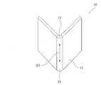
- An example of the high-strength member 10 shown in FIG. 1 is a steel plate 11 that is V-shaped bent.
- the high-strength member 10 has a bent ridge line portion 12 on the side surface of the bent steel plate 11.
- the end surface 13 of the bending ridgeline portion 12 is a plate thickness surface located on the side surface of the bending ridgeline portion 12.
- the bending ridgeline direction D1 in the present invention is a direction parallel to the bending ridgeline portion 12.
- the example of the high-strength member 10 shown in FIG. 1 shows an example in which the number of bent portions is one, but it is assumed that two or more portions are bent to have two or more bent ridge lines. Good.
- ⁇ Tensile strength of the member is 1470 MPa or more>
- the tensile strength (TS) of the high-strength member is 1470 MPa or more.
- the tensile strength (TS) and the yield strength (YS) in the present invention are calculated by measuring the flat portion, which is a non-bent portion of the high-strength member. Further, if the tensile strength (TS) and the yield strength (YS) of the annealed steel sheet before bending (steel sheet after the annealing step) are measured, these measured values are high strengths obtained by using the annealed steel sheet. It can be regarded as a measured value of the tensile strength (TS) and the yield strength (YS) of the member.
- the strength of the member can be calculated by the method described in the examples.
- ⁇ Residual stress on the end face of the bending ridge is 800 MPa or less>
- the residual stress on the end face (plate thickness face) of the bending ridgeline portion of the high-strength member is 800 MPa or less.
- the residual stress is 800 MPa or less, preferably 700 MPa or less, more preferably 600 MPa or less, further preferably 400 MPa or less, and most preferably 200 MPa or less.
- the residual stress on the end surface of the bent ridgeline portion can be calculated by the method as described in the examples of the present specification.
- the longest crack length among the cracks extending in the bending ridge direction from the end face of the bending ridge portion is 10 ⁇ m or less>
- the longest crack length (hereinafter, also simply referred to as crack length) of the cracks extending from the end face of the bending ridge portion in the bending ridge direction is 10 ⁇ m or less.
- the crack length is 10 ⁇ m or less, preferably 8 ⁇ m or less, and more preferably 5 ⁇ m or less.
- the crack length can be calculated by the method as described in the examples of the present specification.
- An example of the embodiment of the method for manufacturing a high-strength member of the present invention is, after cutting out a steel plate having a tensile strength of 1470 MPa or more, chamfering an end face generated by cutting before or after bending, After the chamfering, there is an end face treatment step of heating at a temperature of 270 ° C. or lower.
- one example of the embodiment of the method for producing a high-strength member of the present invention is, after cutting out a steel plate having the above-described composition and the microstructure, end faces produced by cutting are chamfered before or after bending. After the bending process and the chamfering process, there is an end face treatment step of heating at a temperature of 270 ° C. or lower.
- an example of the embodiment of the method for producing a steel sheet for high-strength members of the present invention is obtained by hot rolling and cold rolling a steel (steel material) having the above-mentioned composition, and by the cold rolling.
- the average cooling rate in the temperature range from the annealing temperature to 550 ° C. is 3 ° C./sec or more, and the cooling stop temperature is 350 ° C. or less.
- these steps and a preferable casting step performed before the hot rolling step will be described.
- the temperature shown below means the surface temperature of a slab, a steel plate, etc.
- the casting speed is not particularly limited, but in order to suppress the formation of the above inclusions and improve the delayed fracture resistance, the casting speed is preferably 1.80 m / min or less, more preferably 1.75 m / min or less, It is more preferably 0.70 m / min or less.
- the lower limit is also not particularly limited, but from the viewpoint of productivity, it is preferably 1.25 m / min or more, more preferably 1.30 m / min or more.
- the steel (steel slab) having the above-described composition is subjected to hot rolling.
- the slab heating temperature is not particularly limited, but by setting the slab heating temperature to 1200 ° C. or higher, solid solution promotion of sulfide and Mn segregation are reduced, the amount of coarse inclusions described above is reduced, and delay resistance is delayed. The fracture characteristics tend to improve. Therefore, the slab heating temperature is preferably 1200 ° C or higher. More preferably, it is 1220 ° C. or higher.
- the heating rate during slab heating is preferably 5 to 15 ° C./minute, and the slab soaking time is preferably 30 to 100 minutes.
- the finish rolling finish temperature is preferably 840 ° C or higher.
- the finish rolling end temperature is preferably 840 ° C or higher, and more preferably 860 ° C or higher.
- the finish rolling end temperature is preferably 950 ° C. or lower, more preferably 920 ° C. or lower, because it becomes difficult to cool to the subsequent winding temperature.
- the winding temperature is preferably 630 ° C or lower, and more preferably 600 ° C or lower.
- the lower limit of the winding temperature is not particularly limited, it is preferably 500 ° C. or higher in order to prevent deterioration of cold rolling property.
- the rolled hot rolled steel sheet is pickled and then cold rolled to produce a cold rolled steel sheet.
- the conditions of pickling are not particularly limited. If the rolling reduction is less than 20%, the flatness of the surface may be poor and the structure may become non-uniform, so the rolling reduction is preferably 20% or more, more preferably 30% or more, and It is preferably at least 40%.
- the annealing temperature is AC 3 points or higher, preferably AC 3 points + 10 ° C or higher, and more preferably AC 3 points + 20 ° C or higher.
- the upper limit of the annealing temperature is not particularly limited, but the annealing temperature is preferably 900 ° C. or lower from the viewpoint of suppressing coarsening of austenite and preventing deterioration of delayed fracture resistance.
- soaking may be performed at the annealing temperature.
- the AC3 point is calculated by the following formula. Further, in the following formula, (% element symbol) means the content (mass%) of each element.
- AC 3 points (° C.) 910 ⁇ 203 ⁇ (% C) +45 (% Si) ⁇ 30 (% Mn) ⁇ 20 (% Cu) ⁇ 15 (% Ni) +11 (% Cr) +32 (% Mo) +104 ( % V) +400 (% Ti) +460 (% Al)
- the average cooling rate in the temperature range from the annealing temperature to 550 ° C is 3 ° C / sec or more, and the cooling stop temperature is 350 ° C or less. Cooling is carried out, and thereafter, it is retained in a temperature range of 100 ° C. or higher and 260 ° C. or lower for 20 seconds or more and 1500 seconds or less.
- the average cooling rate in the temperature range from the annealing temperature to 550 ° C is less than 3 ° C / sec, it is difficult to obtain the desired strength because ferrite is excessively generated. Further, since ferrite is generated in the surface layer, it becomes difficult to obtain the bainite and martensite fraction having carbides near the surface layer, and the delayed fracture resistance is deteriorated. Therefore, the average cooling rate in the temperature range from the annealing temperature to 550 ° C. is 3 ° C./sec or more, preferably 5 ° C./sec or more, and more preferably 10 ° C./sec or more.
- the upper limit of the average cooling rate is not particularly specified, but if it becomes too fast, non-uniform martensitic transformation is likely to occur in the coil width direction, and the steel sheet may come into contact with equipment due to shape deterioration. From the viewpoint of obtaining the shape, it is preferably 3000 ° C./s or less.
- the average cooling rate in the temperature range from the annealing temperature to 550 ° C. is “(annealing temperature ⁇ 550 ° C.) / (Cooling time from the annealing temperature to 550 ° C.)” unless otherwise specified.
- the cooling stop temperature is 350 ° C or lower. If the cooling stop temperature exceeds 350 ° C, tempering does not proceed sufficiently, and as-quenched martensite and retained austenite that do not contain carbide in the final structure are excessively generated, and the amount of fine carbide in the steel sheet surface layer decreases. Delayed fracture resistance deteriorates. Therefore, in order to obtain excellent delayed fracture resistance, the cooling stop temperature is 350 ° C. or lower, preferably 300 ° C. or lower, more preferably 250 ° C. or lower.
- the carbide distributed inside the bainite is a carbide that is generated during holding in the low temperature range after quenching, and can become a trap site for hydrogen to trap hydrogen and prevent deterioration of delayed fracture resistance. If the residence temperature is less than 100 ° C. or the residence time is less than 20 seconds, bainite is not formed, and as-quenched martensite containing no carbides is formed. The effect of will not be obtained.
- the residence temperature is 100 ° C. or more and 260 ° C. or less, and the residence time is 20 seconds or more and 1500 seconds or less.
- the residence temperature is preferably 130 ° C. or higher and 240 ° C. or lower, and the residence time is preferably 50 seconds or longer and 1000 seconds or shorter.
- the hot-rolled steel sheet after hot rolling may be subjected to heat treatment for softening the structure, or the surface of the steel sheet may be plated with Zn or Al. Further, after annealing cooling or plating treatment, temper rolling for shape adjustment may be performed.
- End face treatment process In one embodiment of the method for manufacturing a high-strength member of the present invention, after cutting out a steel plate, the end face generated by cutting is chamfered before or after bending, and after the bending and the chamfering, 270 It has an end face treatment step of heating at a temperature of °C or less.
- the cutting referred to in the present invention is meant to include known cutting such as shear cutting (mechanical cutting), laser cutting, electric cutting such as electric discharge machining, and gas cutting.
- the end face treatment process By performing the end face treatment process, it is possible to remove the minute cracks generated when the steel sheet is cut out, reduce the residual stress, make the end face of the bending ridge line less likely to crack, and obtain a member with excellent delayed fracture resistance. You can If the longest crack length among the cracks extending from the end face of the bending ridgeline portion to the bending ridgeline direction can be 10 ⁇ m or less, the amount of chamfering of the end face is not particularly limited, but 200 ⁇ m or more from the surface in order to reduce residual stress. It is preferably removed, and more preferably 250 ⁇ m or more. Further, the method for chamfering the end face is not particularly limited, and for example, any of laser, grinding, and coining treatment may be used. Either the bending process or the end face chamfering process may be performed first, the end face chamfering process may be performed after the bending process, or the end face chamfering process may be performed.
- the formed member after the bending and the surface cutting of the steel plate is heated at a temperature of 270 ° C. or lower. If the heating temperature exceeds 270 ° C., tempering of the martensite structure proceeds, so that it becomes difficult to obtain a desired TS. Therefore, the heating temperature is 270 ° C or lower, preferably 250 ° C or lower. Further, the lower limit of the heating temperature and the heating time are not particularly limited as long as the residual stress on the end face of the bending ridge portion can be set to 800 MPa or less. The heating at a temperature of 270 ° C. or lower may be replaced by the heating performed by coating baking.
- this heating may be performed by heating at least the end face portion subjected to chamfering, and may be heating the entire steel sheet.
- the blank column of the component composition in Table 1 represents that the component is not intentionally added, and includes not only the case where it is not contained (0% by mass) but also the case where it is inevitably contained. Details of each condition of the hot rolling process, the cold rolling process, and the annealing process are shown in Tables 2 to 4.
- the heat-treated steel plate was sheared into small pieces of 30 mm x 110 mm, and in some samples, the end faces generated by shearing were chamfered by laser or grinding before bending. Then, the sample of the steel plate was placed on a die having an angle of 90 °, and the steel plate was pressed by a punch having an angle of 90 ° to perform V-bending. Next, as shown in the side view of FIG. 2, the bent steel plate (member) was tightened with bolts 20 from both sides of the plate surface of the steel plate 11 using a bolt 20, a nut 21, and a taper washer 22.
- CAE Computer Aided Engineering
- Tables 2 to 4 show each condition of the end surface treatment.
- the ones with "-" in the column for chamfering mean that no chamfering was performed, and the ones with "-" in the column for heat treatment temperature (° C) Means no heat treatment.
- the area ratio was an average value of three area ratios obtained from separate SEM images at a magnification of 1500 times. Martensite has a white structure, and bainite has fine carbides deposited inside the black structure. The average particle size of the carbide was calculated as follows. Further, the area ratio is the area ratio for the entire observation range, and was regarded as the area ratio for the entire steel plate structure.
- the term “crack” as used herein refers to a case where a crack having a crack length of 200 ⁇ m or more has occurred.
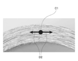
- FIG. 3 is an enlarged view of the end face of the bending ridge line portion, in which the plate thickness center C1 and the measurement direction D2 are shown with reference numerals respectively.
- the members having TS ⁇ 1470 MPa and critical load stress ⁇ YS were regarded as acceptable and shown in Tables 5 to 7 as invention examples. Further, the members with TS ⁇ 1470 MPa or critical load stress ⁇ YS were rejected and shown in Tables 5 to 7 as comparative examples. Further, in Tables 5 to 7, “critical load stress / YS” of 1.00 or more means that critical load stress ⁇ YS.
- the members of the examples of the present invention have high strength and excellent delayed fracture resistance.
Landscapes
- Chemical & Material Sciences (AREA)
- Engineering & Computer Science (AREA)
- Mechanical Engineering (AREA)
- Materials Engineering (AREA)
- Metallurgy (AREA)
- Organic Chemistry (AREA)
- Physics & Mathematics (AREA)
- Thermal Sciences (AREA)
- Crystallography & Structural Chemistry (AREA)
- Heat Treatment Of Sheet Steel (AREA)
- Bending Of Plates, Rods, And Pipes (AREA)
- Heat Treatment Of Articles (AREA)
Priority Applications (6)
| Application Number | Priority Date | Filing Date | Title |
|---|---|---|---|
| US17/289,951 US20220010414A1 (en) | 2018-10-31 | 2019-09-25 | High-strength member, method for manufacturing high-strength member, and method for manufacturing steel sheet for high-strength member |
| MX2021004941A MX2021004941A (es) | 2018-10-31 | 2019-09-25 | Miembro de alta resistencia, metodo para la fabricacion de miembro de alta resistencia, y metodo para la fabricacion de lamina de acero para miembro de alta resistencia. |
| KR1020217012527A KR102525728B1 (ko) | 2018-10-31 | 2019-09-25 | 고강도 부재, 고강도 부재의 제조 방법 및 고강도 부재용 강판의 제조 방법 |
| CN201980071910.XA CN112955575B (zh) | 2018-10-31 | 2019-09-25 | 高强度构件、高强度构件的制造方法和高强度构件用钢板的制造方法 |
| JP2020500927A JP6773251B1 (ja) | 2018-10-31 | 2019-09-25 | 高強度部材及び高強度部材の製造方法 |
| EP19880423.9A EP3875625B1 (en) | 2018-10-31 | 2019-09-25 | High-strength member and method for manufacturing high-strength member |
Applications Claiming Priority (4)
| Application Number | Priority Date | Filing Date | Title |
|---|---|---|---|
| JP2018-204875 | 2018-10-31 | ||
| JP2018204875 | 2018-10-31 | ||
| JP2019121143 | 2019-06-28 | ||
| JP2019-121143 | 2019-06-28 |
Publications (1)
| Publication Number | Publication Date |
|---|---|
| WO2020090302A1 true WO2020090302A1 (ja) | 2020-05-07 |
Family
ID=70462244
Family Applications (1)
| Application Number | Title | Priority Date | Filing Date |
|---|---|---|---|
| PCT/JP2019/037688 WO2020090302A1 (ja) | 2018-10-31 | 2019-09-25 | 高強度部材、高強度部材の製造方法及び高強度部材用鋼板の製造方法 |
Country Status (7)
| Country | Link |
|---|---|
| US (1) | US20220010414A1 (zh) |
| EP (1) | EP3875625B1 (zh) |
| JP (3) | JP6773251B1 (zh) |
| KR (1) | KR102525728B1 (zh) |
| CN (1) | CN112955575B (zh) |
| MX (1) | MX2021004941A (zh) |
| WO (1) | WO2020090302A1 (zh) |
Cited By (3)
| Publication number | Priority date | Publication date | Assignee | Title |
|---|---|---|---|---|
| JPWO2021039776A1 (zh) * | 2019-08-30 | 2021-03-04 | ||
| WO2023037878A1 (ja) * | 2021-09-09 | 2023-03-16 | 日本製鉄株式会社 | 冷延鋼板およびその製造方法 |
| EP4242336A4 (en) * | 2020-12-25 | 2023-10-18 | JFE Steel Corporation | STEEL SHEET, ELEMENT, AND METHODS OF MANUFACTURING SAME |
Citations (10)
| Publication number | Priority date | Publication date | Assignee | Title |
|---|---|---|---|---|
| JP2003166035A (ja) | 2001-11-28 | 2003-06-13 | Nippon Steel Corp | 成形加工後の耐遅れ破壊性に優れた高強度薄鋼板及びその製造方法並びに高強度薄鋼板により作成された自動車用強度部品 |
| JP2008189985A (ja) * | 2007-02-02 | 2008-08-21 | Sumitomo Metal Ind Ltd | 局部延性能に優れた熱延鋼板及びその製造方法 |
| JP2013221198A (ja) * | 2012-04-18 | 2013-10-28 | Nippon Steel & Sumitomo Metal Corp | 冷延鋼板およびその製造方法 |
| JP2014025133A (ja) * | 2012-07-30 | 2014-02-06 | Nippon Steel & Sumitomo Metal | 冷延鋼板およびその製造方法 |
| JP2015117403A (ja) * | 2013-12-18 | 2015-06-25 | Jfeスチール株式会社 | 耐衝撃性および曲げ加工性に優れた高強度溶融亜鉛めっき鋼板およびその製造方法 |
| WO2015093043A1 (ja) * | 2013-12-18 | 2015-06-25 | Jfeスチール株式会社 | 高強度溶融亜鉛めっき鋼板及びその製造方法 |
| JP2017125228A (ja) | 2016-01-13 | 2017-07-20 | Jfeスチール株式会社 | 成形部材の製造方法 |
| JP2017155329A (ja) * | 2016-02-29 | 2017-09-07 | 株式会社神戸製鋼所 | 焼入れ用鋼板及びその製造方法 |
| WO2018030400A1 (ja) * | 2016-08-08 | 2018-02-15 | 新日鐵住金株式会社 | 鋼板 |
| WO2018127984A1 (ja) * | 2017-01-06 | 2018-07-12 | Jfeスチール株式会社 | 高強度冷延鋼板およびその製造方法 |
Family Cites Families (6)
| Publication number | Priority date | Publication date | Assignee | Title |
|---|---|---|---|---|
| JP5668337B2 (ja) * | 2010-06-30 | 2015-02-12 | Jfeスチール株式会社 | 延性及び耐遅れ破壊特性に優れる超高強度冷延鋼板およびその製造方法 |
| WO2016152163A1 (ja) * | 2015-03-25 | 2016-09-29 | Jfeスチール株式会社 | 冷延鋼板およびその製造方法 |
| US20200165708A1 (en) * | 2016-02-10 | 2020-05-28 | Jfe Steel Corporation | High-strength galvanized steel sheet and method of producing the same |
| CN106048412B (zh) * | 2016-06-29 | 2018-04-27 | 宝山钢铁股份有限公司 | 一种相变强化冷加工高强度钢、钢管及钢管的制造方法 |
| KR102226647B1 (ko) * | 2016-09-28 | 2021-03-10 | 제이에프이 스틸 가부시키가이샤 | 강판 및 그 제조 방법 |
| US10982297B2 (en) * | 2016-09-28 | 2021-04-20 | Jfe Steel Corporation | Steel sheet and method for producing the same |
-
2019
- 2019-09-25 US US17/289,951 patent/US20220010414A1/en active Pending
- 2019-09-25 EP EP19880423.9A patent/EP3875625B1/en active Active
- 2019-09-25 WO PCT/JP2019/037688 patent/WO2020090302A1/ja unknown
- 2019-09-25 MX MX2021004941A patent/MX2021004941A/es unknown
- 2019-09-25 KR KR1020217012527A patent/KR102525728B1/ko active IP Right Grant
- 2019-09-25 JP JP2020500927A patent/JP6773251B1/ja active Active
- 2019-09-25 CN CN201980071910.XA patent/CN112955575B/zh active Active
-
2020
- 2020-05-18 JP JP2020086412A patent/JP7163339B2/ja active Active
-
2021
- 2021-11-29 JP JP2021193087A patent/JP2022028885A/ja active Pending
Patent Citations (10)
| Publication number | Priority date | Publication date | Assignee | Title |
|---|---|---|---|---|
| JP2003166035A (ja) | 2001-11-28 | 2003-06-13 | Nippon Steel Corp | 成形加工後の耐遅れ破壊性に優れた高強度薄鋼板及びその製造方法並びに高強度薄鋼板により作成された自動車用強度部品 |
| JP2008189985A (ja) * | 2007-02-02 | 2008-08-21 | Sumitomo Metal Ind Ltd | 局部延性能に優れた熱延鋼板及びその製造方法 |
| JP2013221198A (ja) * | 2012-04-18 | 2013-10-28 | Nippon Steel & Sumitomo Metal Corp | 冷延鋼板およびその製造方法 |
| JP2014025133A (ja) * | 2012-07-30 | 2014-02-06 | Nippon Steel & Sumitomo Metal | 冷延鋼板およびその製造方法 |
| JP2015117403A (ja) * | 2013-12-18 | 2015-06-25 | Jfeスチール株式会社 | 耐衝撃性および曲げ加工性に優れた高強度溶融亜鉛めっき鋼板およびその製造方法 |
| WO2015093043A1 (ja) * | 2013-12-18 | 2015-06-25 | Jfeスチール株式会社 | 高強度溶融亜鉛めっき鋼板及びその製造方法 |
| JP2017125228A (ja) | 2016-01-13 | 2017-07-20 | Jfeスチール株式会社 | 成形部材の製造方法 |
| JP2017155329A (ja) * | 2016-02-29 | 2017-09-07 | 株式会社神戸製鋼所 | 焼入れ用鋼板及びその製造方法 |
| WO2018030400A1 (ja) * | 2016-08-08 | 2018-02-15 | 新日鐵住金株式会社 | 鋼板 |
| WO2018127984A1 (ja) * | 2017-01-06 | 2018-07-12 | Jfeスチール株式会社 | 高強度冷延鋼板およびその製造方法 |
Cited By (5)
| Publication number | Priority date | Publication date | Assignee | Title |
|---|---|---|---|---|
| JPWO2021039776A1 (zh) * | 2019-08-30 | 2021-03-04 | ||
| WO2021039776A1 (ja) * | 2019-08-30 | 2021-03-04 | Jfeスチール株式会社 | 鋼板、部材及びそれらの製造方法 |
| JP6958752B2 (ja) * | 2019-08-30 | 2021-11-02 | Jfeスチール株式会社 | 鋼板、部材及びそれらの製造方法 |
| EP4242336A4 (en) * | 2020-12-25 | 2023-10-18 | JFE Steel Corporation | STEEL SHEET, ELEMENT, AND METHODS OF MANUFACTURING SAME |
| WO2023037878A1 (ja) * | 2021-09-09 | 2023-03-16 | 日本製鉄株式会社 | 冷延鋼板およびその製造方法 |
Also Published As
| Publication number | Publication date |
|---|---|
| JP7163339B2 (ja) | 2022-10-31 |
| EP3875625B1 (en) | 2024-05-22 |
| US20220010414A1 (en) | 2022-01-13 |
| JP2021004414A (ja) | 2021-01-14 |
| CN112955575A (zh) | 2021-06-11 |
| JP6773251B1 (ja) | 2020-10-21 |
| JPWO2020090302A1 (ja) | 2021-02-15 |
| JP2022028885A (ja) | 2022-02-16 |
| KR102525728B1 (ko) | 2023-04-26 |
| MX2021004941A (es) | 2021-06-08 |
| EP3875625A4 (en) | 2021-09-29 |
| KR20210065163A (ko) | 2021-06-03 |
| CN112955575B (zh) | 2022-07-08 |
| EP3875625A1 (en) | 2021-09-08 |
Similar Documents
| Publication | Publication Date | Title |
|---|---|---|
| JP6729835B1 (ja) | 高強度鋼板およびその製造方法 | |
| JP6950835B2 (ja) | 高強度部材、高強度部材の製造方法及び高強度部材用鋼板の製造方法 | |
| JP6801819B2 (ja) | 鋼板、部材およびこれらの製造方法 | |
| WO2017179372A1 (ja) | 高強度鋼板およびその製造方法 | |
| JP2017048412A (ja) | 溶融亜鉛めっき鋼板、合金化溶融亜鉛めっき鋼板、およびそれらの製造方法 | |
| JP6760520B1 (ja) | 高降伏比高強度電気亜鉛系めっき鋼板及びその製造方法 | |
| JP7163339B2 (ja) | 高強度部材および高強度部材の製造方法 | |
| JP6801818B2 (ja) | 鋼板、部材およびこれらの製造方法 | |
| EP3901293B1 (en) | High-strength hot-dip galvanized steel sheet and manufacturing method therefor | |
| CN112867807A (zh) | 高延展性高强度电镀锌系钢板及其制造方法 | |
| CN115715332B (zh) | 镀锌钢板、构件和它们的制造方法 | |
| CN115768915B (zh) | 镀锌钢板、构件和它们的制造方法 | |
| JP2021181624A (ja) | 鋼板、部材及びそれらの製造方法 | |
| JP7028379B1 (ja) | 鋼板、部材及びそれらの製造方法 | |
| JP2010174295A (ja) | 熱間打抜き性に優れたダイクエンチ用鋼板 |
Legal Events
| Date | Code | Title | Description |
|---|---|---|---|
| ENP | Entry into the national phase |
Ref document number: 2020500927 Country of ref document: JP Kind code of ref document: A |
|
| 121 | Ep: the epo has been informed by wipo that ep was designated in this application |
Ref document number: 19880423 Country of ref document: EP Kind code of ref document: A1 |
|
| ENP | Entry into the national phase |
Ref document number: 20217012527 Country of ref document: KR Kind code of ref document: A |
|
| NENP | Non-entry into the national phase |
Ref country code: DE |
|
| ENP | Entry into the national phase |
Ref document number: 2019880423 Country of ref document: EP Effective date: 20210531 |