WO2020085437A1 - Dispositif de commande numérique, dispositif d'apprentissage automatique et procédé de commande numérique - Google Patents
Dispositif de commande numérique, dispositif d'apprentissage automatique et procédé de commande numérique Download PDFInfo
- Publication number
- WO2020085437A1 WO2020085437A1 PCT/JP2019/041726 JP2019041726W WO2020085437A1 WO 2020085437 A1 WO2020085437 A1 WO 2020085437A1 JP 2019041726 W JP2019041726 W JP 2019041726W WO 2020085437 A1 WO2020085437 A1 WO 2020085437A1
- Authority
- WO
- WIPO (PCT)
- Prior art keywords
- vibration
- shaft
- drive shaft
- unit
- vibrations
- Prior art date
Links
Images


Classifications
-
- G—PHYSICS
- G05—CONTROLLING; REGULATING
- G05B—CONTROL OR REGULATING SYSTEMS IN GENERAL; FUNCTIONAL ELEMENTS OF SUCH SYSTEMS; MONITORING OR TESTING ARRANGEMENTS FOR SUCH SYSTEMS OR ELEMENTS
- G05B19/00—Programme-control systems
- G05B19/02—Programme-control systems electric
- G05B19/18—Numerical control [NC], i.e. automatically operating machines, in particular machine tools, e.g. in a manufacturing environment, so as to execute positioning, movement or co-ordinated operations by means of programme data in numerical form
- G05B19/182—Numerical control [NC], i.e. automatically operating machines, in particular machine tools, e.g. in a manufacturing environment, so as to execute positioning, movement or co-ordinated operations by means of programme data in numerical form characterised by the machine tool function, e.g. thread cutting, cam making, tool direction control
-
- G—PHYSICS
- G06—COMPUTING; CALCULATING OR COUNTING
- G06N—COMPUTING ARRANGEMENTS BASED ON SPECIFIC COMPUTATIONAL MODELS
- G06N20/00—Machine learning
-
- B—PERFORMING OPERATIONS; TRANSPORTING
- B23—MACHINE TOOLS; METAL-WORKING NOT OTHERWISE PROVIDED FOR
- B23Q—DETAILS, COMPONENTS, OR ACCESSORIES FOR MACHINE TOOLS, e.g. ARRANGEMENTS FOR COPYING OR CONTROLLING; MACHINE TOOLS IN GENERAL CHARACTERISED BY THE CONSTRUCTION OF PARTICULAR DETAILS OR COMPONENTS; COMBINATIONS OR ASSOCIATIONS OF METAL-WORKING MACHINES, NOT DIRECTED TO A PARTICULAR RESULT
- B23Q15/00—Automatic control or regulation of feed movement, cutting velocity or position of tool or work
- B23Q15/007—Automatic control or regulation of feed movement, cutting velocity or position of tool or work while the tool acts upon the workpiece
- B23Q15/013—Control or regulation of feed movement
-
- G—PHYSICS
- G05—CONTROLLING; REGULATING
- G05B—CONTROL OR REGULATING SYSTEMS IN GENERAL; FUNCTIONAL ELEMENTS OF SUCH SYSTEMS; MONITORING OR TESTING ARRANGEMENTS FOR SUCH SYSTEMS OR ELEMENTS
- G05B2219/00—Program-control systems
- G05B2219/30—Nc systems
- G05B2219/37—Measurements
- G05B2219/37346—Cutting, chip quality
-
- G—PHYSICS
- G05—CONTROLLING; REGULATING
- G05B—CONTROL OR REGULATING SYSTEMS IN GENERAL; FUNCTIONAL ELEMENTS OF SUCH SYSTEMS; MONITORING OR TESTING ARRANGEMENTS FOR SUCH SYSTEMS OR ELEMENTS
- G05B2219/00—Program-control systems
- G05B2219/30—Nc systems
- G05B2219/37—Measurements
- G05B2219/37435—Vibration of machine
Definitions
- the present invention relates to a numerical control device, a machine learning device, and a numerical control method for controlling vibration cutting while vibrating a tool.
- the numerical control device controls the operation of the tool according to the processing program for processing the work piece, and thereby causes the tool to work the work piece.
- Some of these numerical control devices vibrate and cut a workpiece while vibrating the tool at a specific frequency along the tool path.
- the numerical control device described in Patent Document 1 calculates a command movement amount per unit time from a movement command to a tool, calculates a vibration movement amount per unit time from a vibration condition, and calculates a command movement amount and a vibration movement amount. Are combined to calculate a combined movement amount, and vibration cutting is controlled based on the combined movement amount.
- the present invention has been made in view of the above, and for a machine tool that performs processing on one rotating workpiece with a plurality of drive shafts that respectively drive a plurality of tools, vibration cutting is performed. It is an object of the present invention to obtain a numerical control device capable of executing.
- a numerical control device comprising a control operation unit for controlling an axis and a second drive axis for driving a second tool for performing vibration cutting of an object to be machined, the control operation unit comprising:
- the storage unit has a storage unit for storing a processing program for vibration-cutting an object.
- the determination unit that determines whether or not the number of vibrations of the first drive shaft and the second drive shaft follows the rotation speed of the spindle specified in the machining program, and the determination unit, When it is determined that the number of vibrations of at least one of the first drive shaft and the second drive shaft does not follow the rotation speed of the spindle, vibration that follows the rotation speed of the spindle for the drive shaft that is determined not to follow And a vibration frequency calculation unit that calculates the frequency.
- the numerical control device can perform vibration cutting on a machine tool that performs processing on one rotating workpiece with a plurality of drive shafts that respectively drive a plurality of tools. Has the effect.
- Flowchart showing the processing procedure of the numerical control device according to the first embodiment The figure which shows the 2nd example of the machining program which the numerical controller concerning Embodiment 1 uses.
- Flowchart showing the processing procedure of the numerical control device according to the second embodiment The figure which shows the structural example of the numerical control apparatus concerning Embodiment 3.
- FIG. 3 is a diagram showing an example of a hardware configuration of a control calculation unit according to the first to third embodiments.
- a numerical control device, a machine learning device, and a numerical control method according to an embodiment of the present invention will be described below in detail with reference to the drawings.
- the present invention is not limited to these embodiments.
- FIG. 1 is a diagram illustrating a configuration example of a numerical control device according to the first embodiment.
- FIG. 2 is a diagram showing the configuration of the machine tool according to the first embodiment.
- the horizontal direction of the paper surface is the Z-axis direction
- the vertical direction of the paper surface is the X-axis direction.
- the X1 axis and the X2 axis are axes parallel to the X axis
- the Y1 axis and the Y2 axis are axes parallel to the Y axis
- the Z1 axis and the Z2 axis are axes parallel to the Z axis.
- the numerical control (NC: Numerical Control) device 1X is a computer that executes control of low-frequency vibration cutting, which is machining while vibrating the tools 66A and 66B, for a machine tool 110 that performs lathe machining.
- the low frequency vibration may be simply referred to as vibration.
- the numerical controller 1X relatively moves the first tool and the workpiece 70 to be machined by one or more drive shafts including the first drive shaft, and further includes a second drive shaft.
- the machining of the machining workpiece 70 is controlled while the second tool and the machining workpiece 70 are relatively moved by one or more drive shafts. That is, the numerical controller 1X has a first drive shaft that moves the first tool or the work piece 70 and a second drive shaft that moves the second tool or the work piece 70.
- the workpiece 70 is simultaneously vibration-cut by the first tool and the second tool.
- the numerical controller 1X performs vibration cutting on the two drive shafts, so that the vibration of each drive shaft or the rotation of the workpiece 70 should be controlled so as to comply with the constraint condition for realizing the vibration cutting. Control.
- the numerical controller 1X moves one spindle 60, which is a rotation axis of the workpiece 70, a first drive shaft that moves a tool 66A, which is a first tool, and a tool 66B, which is a second tool. And a machine tool 110 having two drive shafts.
- the workpiece 70 which is a workpiece, is a workpiece that is machined by the machine tool 110.
- the first drive shaft is the first shaft 61A and the second drive shaft is the second shaft 61B will be described.
- the center line of the main shaft 60 is shown as the main shaft 60.
- the numerical controller 1X includes a control operation unit 2X, an input operation unit 3, a display unit 4, and a PLC operation unit 5 such as a machine operation panel for operating a PLC (Programmable Logic Controller) 36.
- a control operation unit 2X controls the input operation unit 3 and a display unit 4.
- a PLC operation unit 5 such as a machine operation panel for operating a PLC (Programmable Logic Controller) 36.
- FIG. 1 shows a drive unit 90 that is a component of the machine tool 110.
- the drive unit 90 drives the tool rest 65A of the first system, the tool rest 65B of the second system, and the like included in the machine tool 110.
- the drive unit 90 is a drive mechanism that drives the two tools 66A and 66B while rotating the workpiece 70.
- the drive unit 90 moves the tool 66A along the X1 axis direction and the Z1 axis direction which is the axial direction of the first shaft 61A, and moves the tool 66B along the X2 axis direction and the Z2 axis which is the axial direction of the second shaft 61B. Move along the direction.
- the vibration direction of the tool 66A is the axial direction of the first shaft 61A and the vibration direction of the tool 66B is the axial direction of the second shaft 61B will be described. Since the axial direction depends on the device configuration, the axial direction is not limited to the above direction.
- the drive unit 90 includes servomotors 901 to 904 that move the tools 66A and 66B in the respective axial directions defined on the numerical controller 1X, and detectors 97 to 100 that detect the positions and speeds of the servomotors 901 to 904. Is equipped with. Further, the drive unit 90 includes servo control units for the respective axis directions that control the servo motors 901 to 904 based on a command from the numerical control device 1X. The servo control unit for each axis performs feedback control to the servo motors 901 to 904 based on the position and speed from the detectors 97 to 100.
- the X1 axis servo control section 91 of the servo control section controls the operation of the tool 66A in the X1 axis direction by controlling the servo motor 901.
- the Z1 axis servo control unit 92 controls the operation of the tool 66A in the Z1 axis direction by controlling the servo motor 902.
- the X2-axis servo control unit 93 controls the operation of the tool 66B in the X2-axis direction by controlling the servo motor 903.
- the Z2-axis servo control unit 94 controls the operation of the tool 66B in the Z2-axis direction by controlling the servo motor 904.
- the drive unit 90 further controls the X3 axis servo control unit that controls the operation in the X3 axis direction parallel to the X axis direction, and the Z3 axis direction parallel to the Z axis direction.
- a Z3 axis servo control unit for controlling the operation of In this case, the X3 axis servo control unit controls one servo motor having a detector, and the Z3 axis servo control unit controls one servo motor having a detector.
- the drive unit 90 also includes a spindle motor 911 that rotates the spindle 60 for rotating the workpiece 70, and a detector 211 that detects the position and rotation speed of the spindle motor 911.
- the rotation speed detected by the detector 211 corresponds to the rotation speed of the spindle motor 911.
- the drive unit 90 also includes a spindle servo control unit 200 that controls the spindle motor 911 based on a command from the numerical controller 1X.
- the spindle servo control unit 200 performs feedback control to the spindle motor 911 based on the position and speed from the detector 211.
- the number of rotations of the spindle 60 per unit time is called the spindle rotation speed.
- the spindle rotation speed is, for example, the rotation speed of the spindle 60 per minute. That is, the spindle rotation speed corresponds to the spindle rotation speed.
- the drive unit 90 includes two sets of a spindle motor 911, a detector 211, and a spindle servo control unit 200.
- the input operation unit 3 is a means for inputting information to the control calculation unit 2X.
- the input operation unit 3 is composed of an input means such as a keyboard, a button, or a mouse, and receives an input of a command or the like by the user to the numerical controller 1X, or a machining program or a parameter, and inputs them to the control calculation unit 2X.
- the display unit 4 is configured by a display unit such as a liquid crystal display device, and displays the information processed by the control calculation unit 2X on the display screen.
- the PLC operation unit 5 accepts an operation by the user and sends an instruction corresponding to the operation to the PLC 36.
- the control calculation unit 2X which is a control unit, includes an input control unit 32, a data setting unit 33, a storage unit 34, a screen processing unit 31, an analysis processing unit 37, a control signal processing unit 35, a PLC 36, and an interpolation unit. It has a processing unit 38X, an acceleration / deceleration processing unit 39, and an axis data output unit 40.
- the PLC 36 may be arranged outside the control calculation unit 2X.
- the storage unit 34 has a parameter storage area 341, a machining program storage area 343, a display data storage area 344, and a shared area 345.
- the parameter storage area 341 parameters and the like used in the processing of the control calculation unit 2X are stored.
- the parameter storage area 341 stores control parameters, servo parameters, and tool data for operating the numerical controller 1X.
- the machining program storage area 343 stores a machining program used for machining the machining workpiece 70.
- the machining program according to the first embodiment includes a vibration command that is a command to vibrate the tools 66A and 66B and a movement command that is a command to move the tools 66A and 66B.
- the screen display data displayed on the display unit 4 is stored in the display data storage area 344.
- the screen display data is data for displaying information on the display unit 4.
- the storage unit 34 is provided with a shared area 345 for storing temporarily used data.
- the screen processing unit 31 controls the screen display data stored in the display data storage area 344 to be displayed on the display unit 4.
- the input control unit 32 receives information input from the input operation unit 3.
- the data setting unit 33 causes the storage unit 34 to store the information received by the input control unit 32. That is, the input information received by the input operation unit 3 is written in the storage unit 34 via the input control unit 32 and the data setting unit 33.
- the control signal processing unit 35 is connected to the PLC 36, and receives from the PLC 36 signal information such as a relay that operates the machine tool 110.
- the control signal processing unit 35 writes the received signal information in the shared area 345 of the storage unit 34.
- the interpolation processing unit 38X refers to these pieces of signal information during the machining operation.
- the analysis processing unit 37 outputs an auxiliary instruction to the shared area 345
- the control signal processing unit 35 reads the auxiliary instruction from the shared area 345 and sends it to the PLC 36.
- the auxiliary command is a command other than a command for operating the drive axis which is the numerical control axis.
- An example of the auxiliary instruction is an M code or a T code described later.
- the PLC 36 executes the operation according to this operation.
- the PLC 36 stores a ladder program in which machine operations are described.
- the PLC 36 executes the processing corresponding to the auxiliary instruction to the machine tool 110 according to the ladder program.
- the PLC 36 sends a completion signal indicating that the machine control is completed to the control signal processing unit 35 in order to execute the next block of the machining program.
- control calculation unit 2X the control signal processing unit 35, the analysis processing unit 37, and the interpolation processing unit 38X are connected via the storage unit 34, and writing and reading of information via the storage unit 34 are performed. To do. In the following description, a case where the storage unit 34 is omitted when describing writing and reading of information among the control signal processing unit 35, the analysis processing unit 37, and the interpolation processing unit 38X is omitted. There is.
- the user selects a machining program by inputting the machining program number on the input operation unit 3.
- This machining program number is written in the shared area 345 via the input control unit 32 and the data setting unit 33.
- the analysis processing unit 37 receives the work designation information designating the machining work 70 corresponding to the machining program number selected in the shared area 345 from the shared area 345, triggered by the cycle start of the machine operation panel or the like, the work designation information is received.
- the machining program corresponding to is read from the machining program storage area 343, and analysis processing is performed on each block (each row) of the machining program.
- the analysis processing unit 37 analyzes, for example, a G code (command regarding axis movement etc.), a T code (tool replacement command etc.), an S code (spindle motor rotation speed command), and an M code (machine operation command).
- the analysis processing unit 37 sends the analysis result to the PLC 36 via the shared area 345 and the control signal processing unit 35 when the analyzed line includes the M code or the T code. Further, when the analyzed line includes the M code, the analysis processing unit 37 sends the M code to the PLC 36 via the control signal processing unit 35.
- the PLC 36 executes the machine control corresponding to the M code. When the execution is completed, the result indicating the completion of the M code is written in the storage unit 34 via the control signal processing unit 35.
- the interpolation processing unit 38X refers to the execution result written in the storage unit 34.
- the analysis processing unit 37 sends the analysis result to the interpolation processing unit 38X via the shared area 345. Specifically, the analysis processing unit 37 generates a movement condition corresponding to the G code and sends it to the interpolation processing unit 38X. The analysis processing unit 37 also sends the spindle rotation speed designated by the S code to the interpolation processing unit 38X.
- the movement condition is a condition of the tool feed for the tools 66A and 66B to move the machining position, and is indicated by the speed at which the tool rests 65A and 65B are moved, the position at which the tool rests 65A and 65B are moved, and the like. For example, the tool feed of the tool 66A advances the tool 66A in the axial direction of the first shaft 61A, and the tool feed of the tool 66B advances the tool 66B in the axial direction of the second shaft 61B.
- the analysis processing unit 37 also includes vibration command analysis units 11A and 11B and movement command analysis units 12A and 12B.
- the vibration command analysis unit 11A is a unit that analyzes the vibration command to the first shaft 61A
- the vibration command analysis unit 11B is a unit that analyzes the vibration command to the second shaft 61B.
- the vibration command analysis unit 11A analyzes a vibration command included in a machining program for the first axis 61A (such as a machining program 810A described later) to generate a vibration condition for the first axis 61A, and generates it via the shared area 345.
- the generated vibration condition is sent to the interpolation processing unit 38X.
- the vibration command analysis unit 11B analyzes a vibration command included in a machining program for the second axis 61B (such as a machining program 810B described later) to generate a vibration condition for the second axis 61B, and generates it via the shared area 345.
- the generated vibration condition is sent to the interpolation processing unit 38X.
- the movement command analysis unit 12A analyzes the movement command included in the machining program for the first axis 61A to generate the movement condition of the first axis 61A, and the movement condition generated via the shared area 345 is used as the interpolation processing unit 38X. Send to.
- the movement command analysis unit 12B analyzes the movement command included in the machining program for the second axis 61B to generate the movement condition for the second axis 61B, and the movement condition generated via the shared area 345 is used as the interpolation processing unit 38X. Send to.
- the movement command analysis units 12A and 12B generate movement conditions corresponding to the G code and send them to the interpolation processing unit 38X.
- Examples of the moving condition are the moving speed of the tool rest, the position to move the tool rest, and the like.
- the vibration command to the first shaft 61A is a command to vibrate the first shaft 61A in the Z1 axis direction which is the axial direction of the first shaft 61A
- the vibration command to the second shaft 61B is the X2 command for the second shaft 61B.
- This is a command to vibrate in the axial direction and the Z2 axis direction which is the axial direction of the second shaft 61B.
- the vibration condition is a vibration condition when performing vibration cutting.
- the vibration condition in the first embodiment is the number of vibrations during vibration cutting.
- the number of vibrations of the first shaft 61A is the number of vibrations of the first shaft 61A during one rotation of the main shaft 60
- the number of vibrations of the second shaft 61B is the number of vibrations of the second shaft 61B during one rotation of the main shaft 60.
- the number of vibrations of the first shaft 61A and the number of vibrations of the second shaft 61B respectively correspond to the frequency of vibration based on the time for the main shaft 60 to make one rotation. Therefore, it can be said that the vibration condition in the first embodiment is the frequency of vibration during vibration cutting.
- the vibration frequency of the first shaft 61A corresponds to the vibration frequency of the tool 66A on the first shaft 61A side.
- the number of vibrations of the second shaft 61B corresponds to the number of vibrations of the tool 66B on the second shaft 61B side.
- the number of vibrations of the first shaft 61A is the first number of vibrations
- the number of vibrations of the second shaft 61B is the second number of vibrations.
- the interpolation processing unit 38X includes command movement amount calculation units 21A and 21B, vibration movement amount calculation units 22A and 22B, a determination unit 23, a vibration frequency calculation unit 24, and a synthesis unit 27.
- the vibration frequency calculation unit 24 of the interpolation processing unit 38X synchronizes and follows the vibration of the first shaft 61A and the vibration of the second shaft 61B with the rotation speed of the spindle, so that the rotation speed of the spindle, the vibration frequency of the first shaft 61A, and At least one of the number of vibrations of the second shaft 61B is changed.
- the interpolation processing unit 38X determines whether to change the number of vibrations of the first shaft 61A and the number of vibrations of the second shaft 61B, and sets the number of vibrations of the shaft that is determined to be changed to the number of vibrations according to the spindle rotation speed. change. In this case, the interpolation processing unit 38X changes the number of vibrations so that the vibrations of each axis can be synchronized and follow the rotation speed of the spindle.
- the process of synchronizing the vibration of the first shaft 61A and the main shaft rotation speed adjusts the number of vibrations of the first shaft 61A so that the number of vibrations of the first shaft 61A during one revolution of the main shaft 60 becomes a constant number of vibrations. It is a process to do. Further, the process of synchronizing the vibration of the second shaft 61B and the main shaft rotation speed is performed so that the number of vibrations of the second shaft 61B during one revolution of the main shaft 60 becomes a constant number of vibrations. Is a process for adjusting.
- the process of synchronizing the vibration of the first shaft 61A with the main shaft rotation speed is the process of synchronizing the vibration frequency (frequency) of the first shaft 61A with the main shaft rotation speed, and with the vibration of the second shaft 61B.
- the process of synchronizing the main shaft rotation speed is a process of synchronizing the vibration frequency of the second shaft 61B and the main shaft rotation speed.
- the vibration of the first shaft 61A is defined by the number of vibrations
- the synchronization between the vibration of the first shaft 61A and the main spindle rotation speed is determined by the number of vibrations of the first shaft 61A and the main spindle rotation speed.
- the vibration of the second shaft 61B is defined by the number of vibrations
- the synchronization between the vibration of the second shaft 61B and the main shaft rotation speed is determined by the number of vibrations of the second shaft 61B and the main shaft rotation speed.
- synchronization is sometimes called synchronization.
- the constant number of vibrations in the first shaft 61A is variable, and the number of vibrations can be selected according to the vibration cutting by the first shaft 61A and the second shaft 61B. Further, the constant number of vibrations of the second shaft 61B is variable, and the number of times of vibration cutting by the first shaft 61A and the second shaft 61B can be selected.
- the interpolation processing unit 38X reads, from the shared area 345, the spindle rotation speed, the number of vibrations of the first axis 61A, and the number of vibrations of the second axis 61B.
- the command movement amount calculation units 21A and 21B receive the movement condition which is the analysis result from the analysis processing unit 37, perform the interpolation process on the movement condition, and synthesize the command movement amount per unit time corresponding to the result of the interpolation process. Send to. Specifically, the command movement amount calculation unit 21A calculates the command movement amount for moving the tool rest 65A in a unit time based on the movement condition of the first axis 61A analyzed by the analysis processing unit 37, and the combining unit 27. Send to. Further, the command movement amount calculation unit 21B calculates the command movement amount for moving the tool rest 65B in a unit time based on the movement condition of the second axis 61B analyzed by the analysis processing unit 37, and sends it to the synthesizing unit 27.
- the determination unit 23 adjusts either the number of vibrations of the first shaft 61A or the number of vibrations of the second shaft 61B based on the number of rotations of the main shaft, the number of vibrations of the first shaft 61A, and the number of vibrations of the second shaft 61B. To determine. If the frequency is obtained instead of the number of vibrations, the determination unit 23 calculates the number of vibrations based on the frequency. In order to efficiently divide the chips in vibration cutting, the number of vibrations of the tools 66A and 66B during one revolution of the main shaft 60 needs to be not a natural number, and is (0.5 + N) times (N is 0 or a natural number). ) The neighborhood is desirable. Here, to efficiently divide the chips means to divide the chips into short pieces on average, not to divide the chips having variations in length.
- the number of vibrations of the tools 66A and 66B be in the vicinity of the sum of 0.5 and 0 or a natural number.
- the number of times of vibration of the tools 66A and 66B during one revolution of the main shaft 60 is (0.5 + N) is referred to as a specific number of vibrations.
- An example of the number of vibrations synchronized with the spindle speed is the specific number of vibrations.
- the specific number of vibrations may be in the vicinity of (0.5 + N) times, and a slight deviation may be acceptable. If it is deviated from (0.5 + N) times, the length of the chips will vary somewhat, but for example, the chips cannot be divided or the length of the chips varies by ⁇ 50%. If there is no influence, That is, the number of vibrations of the first shaft 61A and the second shaft 61B may be determined based on the specific number of vibrations.
- the determination unit 23 selects, as an adjustment target, the number of vibrations of the drive shaft that does not follow the main shaft rotation speed or does not reach the specific number of vibrations.
- the determination unit 23 may select a drive shaft that is far away from the number of vibrations that can follow the main shaft rotation speed, or may select a drive shaft that is far away from the specific vibration frequency.
- the frequency of the first shaft 61A is a frequency capable of following the spindle rotational speed (for example, 25 Hz), and the frequency of the second shaft 61B exceeds the frequency capable of following the spindle rotational speed (for example, 100 Hz).
- the determination unit 23 selects the number of vibrations of the second shaft 61B as the adjustment target. The determination unit 23 sends the determination result to the vibration frequency calculation unit 24. The determination unit 23 also sends the spindle speed to the acceleration / deceleration processing unit 39.
- the vibration frequency calculation unit 24 adjusts the vibration frequency of the drive shaft based on the vibration frequency and the spindle rotation speed such that the vibration frequency becomes the specific vibration frequency and can follow the spindle rotation speed.
- the vibration frequency calculation unit 24 sets 0.5 times or 1.5 times as the vibration frequency of the second axis 61B.
- the vibration frequency calculation unit 24 sets, for example, among the plurality of vibration frequency candidates, the vibration frequency closest to the initial vibration frequency as the vibration frequency of the second shaft 61B. That is, the vibration frequency calculation unit 24 changes the vibration frequency by selecting a candidate having the smallest difference between before and after the vibration frequency is changed.
- the vibration frequency calculation unit 24 associates the adjusted vibration frequency and the non-adjusted vibration frequency with the first shaft 61A or the second shaft 61B, and sends them to the vibration movement amount calculation unit 22B. .
- the vibration frequency calculation unit 24 associates the adjusted vibration frequency and the non-adjusted vibration frequency with the first shaft 61A or the second shaft 61B, and sends them to the vibration movement amount calculation unit 22B.
- the vibration frequency calculation unit 24 associates the adjusted vibration frequency and the non-adjusted vibration frequency with the first shaft 61A or the second shaft 61B, and sends them to the vibration movement amount calculation unit 22B.
- the vibration frequency calculation unit 24 associates the adjusted vibration frequency and the non-adjusted vibration frequency with the first shaft 61A or the second shaft 61B, and sends them to the vibration movement amount calculation unit 22B.
- the vibration movement amount calculation unit 22A calculates the vibration movement of the first shaft 61A based on the vibration count of the first shaft 61A sent from the vibration count calculation unit 24 or the vibration condition of the first shaft 61A in the shared area 345. Calculate the amount.
- the vibration movement amount of the first shaft 61A is the movement amount per unit time for vibrating the tool 66A.
- the vibration movement amount calculation unit 22A sends the calculated vibration movement amount of the first shaft 61A to the combining unit 27.
- the vibration movement amount calculation unit 22B calculates the vibration movement of the second shaft 61B based on the vibration count of the second shaft 61B sent from the vibration count calculation unit 24 or the vibration condition of the second shaft 61B in the shared area 345. Calculate the amount.
- the vibration movement amount of the second shaft 61B is the movement amount per unit time for vibrating the tool 66B.
- the vibration movement amount calculation unit 22B sends the calculated vibration movement amount of the second shaft 61B to the combining unit 27.
- the movement of the tools 66A and 66B is the sum of the movement for vibration cutting and the movement in the direction (cutting direction) for advancing the machining with respect to the machining workpiece 70.
- the cutting direction is the Z-axis direction in FIG. Therefore, the synthesizing unit 27 adds the vibration movement amount for vibration cutting and the movement amount in the cutting direction for advancing the machining of the workpiece 70.
- the combining unit 27 calculates the combined movement amount by combining the command movement amount sent from the command movement amount calculation unit 21A and the vibration movement amount sent from the vibration movement amount calculation unit 22A. To generate.
- the vibration movement amount may be indicated by a waveform.
- the combined movement amount may also be indicated by a waveform.
- the combining unit 27 sends the combined movement amount, which is the result of the interpolation processing, to the acceleration / deceleration processing unit 39.
- the combining unit 27 sends the combined movement amount for the first shaft 61A and the combined movement amount for the second shaft 61B to the acceleration / deceleration processing unit 39.
- the acceleration / deceleration processing unit 39 performs acceleration / deceleration processing for smoothly changing the acceleration on the result of the interpolation processing supplied from the interpolation processing unit 38X.
- the acceleration / deceleration processing unit 39 performs acceleration / deceleration processing when starting and stopping the movement. Specifically, the acceleration / deceleration processing unit 39 generates a movement command to the first axis 61A based on the combined movement amount for the first axis 61A, and based on the combined movement amount for the second axis 61B, A movement command to the second axis 61B is generated.
- the position command processed by the acceleration / deceleration processing unit 39 is a speed command per unit time.
- the acceleration / deceleration processing unit 39 generates an acceleration / deceleration command for the X1, X2, Z1 and Z2 axes.
- the acceleration / deceleration processing unit 39 sends a speed command, which is the processing result of the acceleration / deceleration processing, to the axis data output unit 40.
- the acceleration / deceleration processing unit 39 does not perform acceleration / deceleration processing on the spindle rotational speed.
- the acceleration / deceleration processing unit 39 sends a rotation speed command corresponding to the rotation speed of the spindle to the axis data output unit 40.
- the rotation speed command generated by the acceleration / deceleration processing unit 39 is a step command.
- Axis data output unit 40 outputs a speed command to drive unit 90. Specifically, the axis data output unit 40 outputs a speed command for the X1 axis to the X1 axis servo control unit 91, and outputs a speed command for the Z1 axis to the Z1 axis servo control unit 92. The axis data output unit 40 also outputs a speed command for the X2 axis to the X2 axis servo control unit 93 and a speed command for the Z2 axis to the Z2 axis servo control unit 94. Further, the axis data output unit 40 outputs a rotation speed command to the spindle 60 to the spindle servo control unit 200.
- the X1 axis servo control unit 91, the Z1 axis servo control unit 92, the X2 axis servo control unit 93, the Z2 axis servo control unit 94, and the spindle servo control unit 200 operate the tool 66A in the X1 axis direction and the Z1 axis direction. And the operation of the tool 66B in the X2-axis direction and the Z2-axis direction, and the rotating operation of the spindle 60.
- the PLC 36 When machining by the machine tool 110 is started, the PLC 36 outputs a cycle start signal to the control signal processing unit 35, and the control signal processing unit 35 outputs the cycle start signal to the interpolation processing unit 38X. As a result, the interpolation processing unit 38X activates the analysis processing unit 37.
- the analysis processing unit 37 reads the machining program for each block and analyzes the machining program, and stores the vibration conditions, the movement conditions, and the spindle rotation speed, which are the analysis results, in the shared area 345. Then, the interpolation processing unit 38X calculates the combined movement amount per unit time for the first axis 61A and the combined movement amount per unit time for the second axis 61B based on the analysis result of the analysis processing unit 37. It is sent to the acceleration / deceleration processing unit 39.
- the acceleration / deceleration processing unit 39 generates an acceleration / deceleration movement command for each axis based on the combined movement amount from the interpolation processing unit 38X.
- This movement command is output from the axis data output unit 40 to the drive unit 90, and the drive unit 90 controls the operation of each axis according to the movement command.
- the machine tool 110 is a lathe with one spindle and two turrets, in which a turret 65A has a first shaft 61A and a turret 65B has a second shaft 61B.
- a lathe with one spindle and two turrets is a lathe equipped with one spindle and two turrets.
- the turrets 65A and 65B are also called turrets.
- An example of the machine tool 110 is a turret lathe.
- the machine tool 110 has a headstock equipped with a first spindle 75.
- the first spindle 75 rotates with the work 70 attached, and thereby rotates the work 70.
- the rotation axis of the workpiece 70 by the first spindle 75 is the spindle 60 provided on the headstock.
- the machine tool 110 includes a tool rest 65A that is a first tool rest and a tool rest 65B that is a second tool rest, the tool rest 65A is provided with a first shaft 61A, and the tool rest 65B is provided with a second end.
- a shaft 61B is provided.
- the tool rest 65A is movable in the X1 axis direction and the Z1 axis direction, and the tool rest 65B is movable in the X2 axis direction and the Z2 axis direction.
- the Z1 axis is the first axis 61A and the Z2 axis is the second axis 61B.
- the tool rest 65A is a tool rest on the first shaft 61A side
- the tool rest 65B is a tool rest on the second shaft 61B side.
- the tool rests 65A and 65B are swivel tool rests.
- a plurality of tools 66A can be attached to the tool rest 65A, and the tools 66A to be used are switched by rotating the tools 66A.
- the tool rest 65B can be attached with a plurality of tools 66B, and the tools 66B to be used are switched by rotating the tools 66B.
- the tool base 66A vibrates and cuts the workpiece 70 by vibrating the tool rest 65A in the Z1 axis direction.
- the tool rest 65B vibrates in the Z2 axis direction
- the tool 66B vibrates and cuts the work 70.
- the vibration of the tool rest 65A may be described as the vibration of the tool 66A.
- the vibration of the tool rest 65B may be described as the vibration of the tool 66B.
- the vibration conditions of the machine tool 110 according to the first embodiment are set to the following (L1-1) to (L1-2).
- the vibration condition is an example of a condition for achieving good finishing accuracy of the object to be machined and for further finely cutting chips.
- (L1-1) The number of vibrations of the tools 66A and 66B during one revolution of the main shaft 60 is the same on the first shaft 61A side and the second shaft 61B side. It should be noted that both the first shaft 61A side and the second shaft 61B side operate at the number of vibrations synchronized with the main shaft rotation speed during vibration cutting.
- the amplitude of vibration is the same on the first shaft 61A side and the second shaft 61B side.
- the number of vibrations and the amplitude are the same on the first shaft 61A side and the second shaft 61B side, but they may be different. This is because in the machine tool 110, the vibration of the first shaft 61A is not transmitted to the second shaft 61B.
- FIG. 3 is a diagram showing a first example of a machining program used by the numerical control device according to the first embodiment.
- the machining program 81P is used when the numerical controller 1X controls the machine tool 110. Therefore, the machining program 81P includes a machining program 810A for the first axis 61A and a machining program 810B for the second axis 61B.
- the spindle rotation speed command M3 S1 in the machining program 81P is a spindle rotation speed command to the spindle 60.
- M3 S1 3000 is a command to rotate the spindle 60 3000 times per minute.
- G0 is a positioning command
- G165 is a low frequency vibration command
- G1 is a movement command.
- “A” defined by G165 is the amplitude of vibration
- “D” is the number of vibrations during one rotation of the main shaft 60.
- G0 in the machining program 810A positions the tool 66A
- G0 in the machining program 810B positions the tool 66B.
- the tool 66A vibrates in the Z1 axis direction with the amplitude and the number of vibrations designated by G165.
- G165 When G165 is used in the machining program 810A for the first axis 61A, the tool 66A vibrates in the Z1 axis direction with the amplitude and the number of vibrations designated by G165.
- a case is shown in which the tool 66A is vibrated with an amplitude of 0.2 mm and a vibration frequency of 0.5 times during one rotation of the main shaft 60.
- the tool 66B vibrates with the amplitude and the number of vibrations designated by G165.
- G165 a case is shown in which the tool 66B is vibrated with an amplitude of 0.3 mm and a number of vibrations of 6.5 times during one rotation of the main shaft 60.
- the machining program 810A has a vibration frequency of 0.5
- the machining program 810B has a vibration frequency of 6.5.
- the frequency of vibration when the number of vibrations is 6.5 is larger than, for example, 100 Hz, which can follow the rotation speed of the spindle, so the determination unit 23 adjusts the number of vibrations of the second shaft 61B as an adjustment target.
- the vibration frequency calculation unit 24 sets the vibration frequency of the second shaft 61B to 1.5 times, which is the closest to the vibration frequency designated by the original machining program 810B, among the specific vibration frequencies that can follow the spindle rotation speed.
- the numerical controller 1X executes the same processing as when the machining program in which the number of vibrations of the second axis 61B is changed to 1.5 times is executed.
- the machining program 81Q is a machining program in which the number of vibrations of the second axis 61B of the machining program 81P is changed to 1.5 times.
- the machining program 81Q includes a machining program 810A and a machining program 811B.
- the machining program 811B is obtained by changing the number of vibrations of the second shaft 61B with respect to the machining program 810B.
- the numerical controller 1X may actually rewrite the machining program 81P into the machining program 81Q and execute the machining program 81Q.
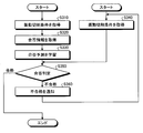
- FIG. 4 is a flowchart of a processing procedure of the numerical control device according to the first embodiment.
- FIG. 4 shows a control processing procedure for the machine tool 110 by the numerical controller 1X.
- the analysis processing unit 37 determines whether or not the vibration command in the machining program is a vibration command for two or more axes for one spindle (step S10). That is, the analysis processing unit 37 determines whether or not the vibration command in the machining program is a vibration command to the machine tool having one spindle and two or more drive axes.
- the numerical controller 1X executes the machining control according to the machining program without changing the number of vibrations.
- the determination unit 23 reads the spindle rotation speed from the shared area 345 and acquires it (step S20). Further, the determination unit 23 reads out and acquires the number of vibrations, which is a vibration condition, from the shared area 345 (step S30). Specifically, the determination unit 23 acquires the number of vibrations of the first shaft 61A and the number of vibrations of the second shaft 61B.
- the determination unit 23 determines which of the first shaft 61A and the second shaft 61B the vibration frequency is changed based on the spindle rotation speed and the vibration frequency (step S40). At this time, the determination unit 23 determines whether or not the frequency of vibration follows the spindle rotation speed based on the spindle rotation speed and the vibration frequency, and also determines whether the vibration frequency is synchronized with the spindle rotation speed. To do.
- the determination unit 23 sends the determination result to the vibration frequency calculation unit 24.
- the vibration frequency calculation unit 24 changes the vibration frequency of the drive shaft, which is determined to be changed, to a specific vibration frequency that can follow and synchronize with the spindle rotation speed (step S50).
- the vibration movement amount calculation unit 22A calculates the vibration movement amount of the first shaft 61A based on the main shaft rotation speed and the number of vibrations of the first shaft 61A, and the vibration movement amount calculation unit 22B calculates the main shaft rotation speed and the second speed.
- the vibration movement amount of the second shaft 61B is calculated based on the number of vibrations of the shaft 61B.
- command movement amount calculation unit 21A calculates the command movement amount of the first axis 61A based on the movement condition from the analysis processing unit 37, and the command movement amount calculation unit 21B calculates the movement condition from the analysis processing unit 37.
- the command movement amount of the second axis 61B is calculated based on
- the combining unit 27 combines the command movement amount and the vibration movement amount (step S60). Specifically, the combining unit 27 generates the combined movement amount of the first shaft 61A by combining the command movement amount of the first shaft 61A and the vibration movement amount of the first shaft 61A, and the second shaft 61B. The combined movement amount of the second shaft 61B is generated by synthesizing the command movement amount of (1) and the vibration movement amount of the second shaft 61B. After that, the control calculation unit 2X controls the first shaft 61A by using the combined movement amount of the first shaft 61A and controls the second shaft 61B by using the combined movement amount of the second shaft 61B.
- the numerical controller 1X may change both the number of vibrations of the first shaft 61A and the number of vibrations of the second shaft 61B.
- a machining program when both the number of vibrations of the first shaft 61A and the number of vibrations of the second shaft 61B are changed will be described.
- FIG. 5 is a diagram showing a second example of a machining program used by the numerical control device according to the first embodiment.
- the machining program 82P is used when the numerical controller 1X controls the machine tool 110.
- the machining program 82P includes a machining program 812A for the first axis 61A and a machining program 812B for the second axis 61B.
- the processing program 812B is the same processing program as the processing program 810B described in FIG.
- the machining program 812A differs from the machining program 810A described with reference to FIG. 3 in the number of vibrations of G165.
- the number of vibrations of G165 in the machining program 812A is 5.5.
- the vibration frequency calculation unit 24 changes the vibration frequency of both the first shaft 61A and the second shaft 61B.
- the vibration frequency calculation unit 24 changes the vibration frequency of the second shaft 61B to 1.5 times by the method described in FIG.
- the number of specific vibrations that can follow the main shaft rotation speed with respect to the first shaft 61A is 0.5 times or 1.5 times.
- the initial vibration frequency of the first shaft 61A is smaller than the initial vibration frequency of the second shaft 61B.
- the vibration frequency calculation unit 24 selects, from among the plurality of vibration frequency candidates, the vibration frequency that is smaller than the vibration frequency set for the second axis 61B. Note that the vibration frequency calculation unit 24 may select the one that is closest to the initial vibration frequency from the plurality of vibration frequency candidates.
- the numerical controller 1X executes the same process as when the machining program is executed in which the number of vibrations of the first axis 61A is changed to 0.5 and the number of vibrations of the second axis 61B is changed to 1.5.
- the machining program 82Q is a machining program in which the number of vibrations of the first axis 61A of the machining program 82P is changed to 0.5 and the number of vibrations of the second axis 61B is changed to 1.5.
- the machining program 82Q includes a machining program 813A and a machining program 813B.
- the machining program 813A has the number of vibrations of the first axis 61A changed with respect to the machining program 812A
- the machining program 813B has the number of vibrations of the second axis 61B changed with respect to the machining program 812B. It is a thing.
- the numerical controller 1X may actually rewrite the machining program 82P into the machining program 82Q and execute the machining program 82Q.
- the drive shaft whose number of vibrations is changed may be one shaft or two or more shafts.
- the number of vibrations of the first shaft 61A or the second shaft 61A is adjusted so that the number of vibrations of the first shaft 61A and the number of vibrations of the second shaft 61B can be synchronized with and follow the rotational speed of the main shaft. Since the number of vibrations of 61B is changed, it is possible to perform vibration cutting on the machine tool 110 with a plurality of drive shafts.
- Embodiment 2 Next, a second embodiment of the present invention will be described with reference to FIGS. 6 to 8.
- the main shaft rotation speed is changed so that the number of vibrations of each drive shaft can be synchronized with the main shaft rotation speed. That is, in the first embodiment, the rotation speed of the main shaft is maintained and the number of vibrations of the drive shaft is changed, whereas in the second embodiment, the number of vibrations of the drive shaft is maintained and the rotation speed of the main shaft is changed.
- FIG. 6 is a diagram illustrating a configuration example of the numerical control device according to the second embodiment.
- those having the same functions as those of the numerical controller 1X according to the first embodiment shown in FIG. 1 are designated by the same reference numerals, and a duplicate description will be omitted.
- the numerical control device 1Y is a computer having the same configuration as the numerical control device 1X, and causes the machine tool 110 to perform vibration cutting.
- the numerical control device 1Y includes a control calculation unit 2Y instead of the control calculation unit 2X as compared with the numerical control device 1X.
- the control calculation unit 2Y includes an interpolation processing unit 38Y instead of the interpolation processing unit 38X as compared with the control calculation unit 2X.
- the interpolation processing unit 38Y includes a spindle rotation speed calculation unit 25, instead of the vibration frequency calculation unit 24, as compared with the interpolation processing unit 38X.
- the determination unit 23 of the second embodiment determines whether or not the number of vibrations of the first shaft 61A is synchronized with the number of rotations of the main shaft, based on the number of vibrations of the first shaft 61A and the number of rotations of the main shaft. When the frequency corresponding to the number of vibrations of the first shaft 61A is within a specific range, the determination unit 23 determines that the number of vibrations of the first shaft 61A is synchronized with the main shaft rotation speed.
- the determination unit 23 determines whether or not the number of vibrations of the second shaft 61B is synchronized with the number of rotations of the main shaft, based on the number of vibrations of the second shaft 61B and the number of rotations of the main shaft. When the frequency corresponding to the number of vibrations of the second shaft 61B is within a specific range, the determination unit 23 determines that the number of vibrations of the second shaft 61B is synchronized with the main shaft rotation speed.
- the spindle rotation speed calculation unit 25 determines whether the first rotation speed of the first shaft 61A or the second rotation speed of the second shaft 61B is not synchronized with the rotation speed of the main shaft or cannot follow the rotation speed of the main shaft.
- the main shaft rotation speed is changed so that the number of vibrations of the shaft 61A and the second shaft 61B synchronizes and follows the main shaft rotation speed.
- the spindle rotation speed calculation unit 25 changes the spindle rotation speed based on the number of vibrations of the first shaft 61A and the second shaft 61B.
- the spindle rotation speed calculation unit 25 adopts the spindle rotation speed closest to the initial spindle rotation speed.
- the spindle rotation speed calculation unit 25 sends the changed spindle rotation speed to the vibration movement amount calculation units 22A and 22B and the acceleration / deceleration processing unit 39.
- the spindle rotation speed calculation unit 25 sends the spindle rotation speed as it is to the vibration movement amount calculation units 22A and 22B and the acceleration / deceleration processing unit 39.
- the vibration movement amount calculation unit 22A calculates the vibration movement amount of the first shaft 61A based on the spindle rotation speed and the vibration frequency of the first shaft 61A sent from the spindle rotation speed calculation unit 25.
- the vibration movement amount calculation unit 22B calculates the vibration movement amount of the second shaft 61B based on the spindle rotation speed and the vibration frequency of the second shaft 61B sent from the spindle rotation speed calculation unit 25.
- the other processing by the interpolation processing unit 38Y is the same as the processing by the interpolation processing unit 38X.
- FIG. 7 is a diagram showing an example of a machining program used by the numerical control device according to the second embodiment.
- the machining program 83P is used when the numerical controller 1Y controls the machine tool 110.
- the machining program 83P includes a machining program 814A for the first axis 61A and a machining program 814B for the second axis 61B.
- the processing program 814A is the same processing program as the processing program 810A described in FIG.
- the machining program 814B differs from the machining program 810B described in FIG. 3 in the number of vibrations of G165.
- the number of vibrations of G165 in the machining program 814B is 2.5 times.
- the determination unit 23 determines whether or not the number of vibrations of the first shaft 61A is synchronous with and can follow the number of rotations of the first shaft 61A based on the number of vibrations of the first shaft 61A of 1.5 and the number of rotations of the main shaft of 3000. To judge.
- the number of vibrations of the first shaft 61A can be synchronized with and can follow the number of rotations of the main shaft.
- the determination unit 23 can synchronize and follow the number of vibrations of the second shaft 61B with the main shaft rotation speed. Determine whether or not.
- the number of vibrations of the second shaft 61B is synchronized with the spindle rotation speed, but cannot follow the spindle rotation speed. That is, the vibration cutting 2.5 times per one rotation of the spindle with 3000 rotations of the spindle per minute is a mechanical structural factor of the machine tool 110 (for example, characteristics such as inertia), and the mechanical device cannot follow the vibration machining. Cannot be divided.
- the vibration waveform of the tool 66B becomes dull due to structural factors of the machine tool 110, that is, the ideal vibration waveform according to the vibration command cannot be realized.
- the vibration waveform of the Mth rotation (M is a natural number) by the tool 66B and the vibration waveform of the (M + 1) th rotation do not overlap. Therefore, if the main spindle rotation speed is increased too much, the number of vibrations of the second shaft 61B cannot follow the main spindle rotation speed, and the chips of the workpiece 70 cannot be divided. Therefore, a method of setting the spindle rotation speed that can be followed by the vibration frequency will be described below.
- the spindle rotation speed calculation unit 25 changes the spindle rotation speed in order to make the vibration frequency of the second shaft 61B follow the spindle rotation speed while maintaining the chip breaking effect to the same degree.
- the spindle rotation speed calculation unit 25 calculates the first vibration frequency f1 corresponding to the number of vibrations of the first shaft 61A.
- this first vibration frequency f1 is provisionally applied as the second vibration frequency f2 of the second shaft 61B.
- the spindle rotation speed calculation unit 25 determines the ideal spindle of the second shaft 61B based on the number of vibrations of the second shaft 61B of 2.5 times and the second vibration frequency f2 provisionally applied to the second shaft 61B.
- the rotation speed S2 is provisionally calculated.
- the spindle rotational speed is adjusted by selecting from a range between S1 and S2.
- the spindle rotation speed calculation unit 25 calculates an average value (intermediate value) of the spindle rotation speed of the first shaft 61A and the calculated spindle rotation speed of the second shaft 61B, and calculates the average value (intermediate value). It is provisionally set as the common spindle rotation speed Sc of the first shaft 61A and the second shaft 61B.
- the first vibration frequency f1c is recalculated from the main shaft speed Sc and the number of vibrations of the first shaft 61A 1.5 times, and it is confirmed whether the first vibration frequency f1c can follow the main shaft speed Sc.
- the second vibration frequency f2c is recalculated from the main shaft speed Sc and the number of vibrations of the second shaft 62B 2.5 times, and it is confirmed whether the second vibration frequency f2c can follow the main shaft speed Sc. .
- the temporarily set spindle rotation speed Sc is adopted as the changed spindle rotation speed.
- the spindle rotation speed calculation unit 25 first sets 2400 rotations, which is the average value (intermediate value) of the initial spindle rotation speed S1 of 3000 rotations and S2 of 1800 rotations, to the common spindle rotation speed Sc. Temporarily set. When the spindle rotation speed Sc is 2400 times, the first shaft 61A and the second shaft 61B can follow and synchronize with each other, and therefore the spindle rotation speed Sc is determined to be 2400 times. Then, the spindle rotation speed calculation unit 25 changes the spindle rotation speed of 3000 rotations to 2400 rotations.
- the spindle rpm calculator 25 sets the initial spindle rpm to a common spindle rpm. May be.
- the spindle rotation speed Sc is temporarily set again, and the same steps are repeated.
- the spindle rotation speed may be set again from between the spindle rotation speeds Sc and S2.
- the spindle rotation speed may be set again from between Sc and S1.
- a machining program 83Q is a machining program in which the spindle speed of the machining program 82P is changed to 2400 revolutions.
- the machining program 83Q includes a machining program 815A and a machining program 814B.
- the machining program 815A is different from the machining program 814A in that the spindle rotational speed is changed.
- the numerical controller 1Y may actually rewrite the machining program 83P into the machining program 83Q and execute the machining program 83Q.
- FIG. 8 is a flowchart showing a processing procedure of the numerical control device according to the second embodiment.
- FIG. 8 shows a control processing procedure for the machine tool 110 by the numerical controller 1Y. It should be noted that, of the processes in FIG. 8, the description of the processes similar to those described in FIG. 4 will be omitted.
- steps S110 to S130 in FIG. 8 is the same as the processing of steps S10 to S30 in FIG.
- the determination unit 23 determines whether to change the spindle rotation speed based on the spindle rotation speed and the number of vibrations (step S140).
- the vibration condition here is the number of vibrations. Therefore, the determination unit 23 here determines whether or not the frequency of vibration corresponding to the number of vibrations of the first shaft 61A can follow the rotation speed of the spindle, and the frequency of vibration corresponding to the number of vibrations of the second shaft 61B. , It is determined whether or not the spindle rotation speed can be followed. When the frequency of the first shaft 61A or the frequency of the second shaft 61B cannot follow the spindle rotation speed, for example, when the chips of the work 70 cannot be divided, the determination unit 23 determines to change the spindle rotation speed. .
- the determination unit 23 determines whether or not the number of vibrations of the first shaft 61A and the second shaft 61B is synchronized with the main shaft rotation speed. When the number of vibrations of the first shaft 61A or the number of vibrations of the second shaft 61B is not synchronized with the spindle rotation speed, the determination unit 23 determines to change the spindle rotation speed.
- the synchronization means that the tool vibrates (0.5 + N) times for one rotation of the spindle. It is preferable that they are completely synchronized, but it does not matter if the number of vibrations of the tool per one rotation of the spindle is about (0.5 + N).
- the determination unit 23 determines not to change the spindle rotation speed.
- the determination unit 23 may determine to change the spindle rotation speed only when the first shaft 61A and the second shaft 61B cannot follow the spindle rotation speed.
- the determination unit 23 sends the determination result to the vibration frequency calculation unit 24.
- the spindle rotation speed calculation unit 25 calculates the spindle rotation speed that matches the vibration frequency of the first shaft 61A and the second shaft 61B based on the spindle rotation speed and the vibration frequency (step S150). Specifically, the spindle rotational speed calculation unit 25 sets a frequency that can be followed for the drive axis that is determined not to be able to follow the spindle rotational speed, and then sets the first axis 61A and the second axis. The spindle rotational speed that can be synchronized and followed by the vibration frequency of 61B is calculated.
- the spindle rotation speed calculation unit 25 changes the initial spindle rotation speed to the calculated spindle rotation speed (step S160).
- the numerical controller 1Y executes a normal operation according to the machining program without changing the spindle rotation speed.
- the vibration movement amount calculation unit 22B calculates the vibration movement amount of the first shaft 61A based on the spindle rotation speed and the vibration frequency of the first shaft 61A, and based on the spindle rotation speed and the vibration frequency of the second shaft 61B. Then, the amount of vibration movement of the second shaft 61B is calculated.
- the combining unit 27 generates the combined movement amount by combining the command movement amount and the vibration movement amount (step S170).
- the numerical controller 1Y may execute both the change of the main shaft rotation speed and the change of the first shaft 61A or the second shaft 61B. In other words, the numerical controller 1Y changes at least one of the spindle rotation speed, the first shaft 61A, and the second shaft 61B.
- the spindle rotational speed is changed so that the vibration frequency of the first shaft 61A and the vibration frequency of the second shaft 61B can be synchronized with and follow the spindle rotational speed.
- Embodiment 3 Next, a third embodiment of the invention will be described with reference to FIGS. 9 to 14.
- vibration cutting is not started by the other drive shaft, and vibration cutting is performed on both drive shafts. After that, both drive shafts perform vibration cutting at the changed spindle speed.
- FIG. 9 is a diagram illustrating a configuration example of the numerical control device according to the third embodiment.
- constituent elements that achieve the same functions as those of the numerical control device 1X of the first embodiment shown in FIG. 1 are designated by the same reference numerals, and a duplicate description will be omitted.
- the numerical control device 1Z is a computer having the same configuration as the numerical control device 1X, and causes the machine tool 110 to perform vibration cutting.
- the numerical controller 1Z includes a control calculator 2Z instead of the control calculator 2X as compared with the numerical controller 1X.
- the control calculation unit 2Z includes an interpolation processing unit 38Z instead of the interpolation processing unit 38X, as compared with the control calculation unit 2X.
- the interpolation processing unit 38Z further includes a standby control unit 26, as compared with the interpolation processing unit 38X.
- the standby control unit 26 determines whether or not it is time to change the spindle rotation speed.
- the numerical controller 1Z permits the vibration cutting of one of the drive shafts, but does not permit the vibration cutting of both of the drive shafts, until the spindle rotational speed is changed. Further, if it is not the timing for changing the spindle rotation speed, the standby control unit 26 causes the spindle rotation speed changing process to wait until the timing for changing the spindle rotation speed is reached.
- the timing at which the spindle rotation speed can be changed is the timing at which vibration cutting is not performed on both the first shaft 61A and the second shaft 61B. If one of the first shaft 61A and the second shaft 61B starts vibration cutting on the workpiece 70 before changing the spindle rotation speed, the standby control unit 26 executes vibration cutting. Not start vibration cutting on the other drive shaft.
- the standby control unit 26 changes the spindle rotation speed at the timing when vibration cutting is not executed on one drive shaft. That is, the standby control unit 26 changes the spindle rotational speed while prohibiting the vibration cutting of both the shafts when the vibration cutting is not performed on both the first shaft 61A and the second shaft 61B.
- the period during which the vibration cutting is not performed is during execution of the G0 positioning command, waiting for the operation of the first axis 61A and the operation of the second axis 61B, and the like.
- the numerical controller 1Z causes both the first shaft 61A and the second shaft 61B to perform vibration cutting.
- FIG. 10 is a diagram showing a first example of a machining program used by the numerical control device according to the third embodiment.
- the machining program 84 is used when the numerical controller 1Z controls the machine tool 110.
- the machining program 84 includes a machining program 816A for the first axis 61A and a machining program 816B for the second axis 61B.
- the machining program 816A may be executed before the spindle speed is changed, and the processing of the machining program 816B may be delayed from the processing of the machining program 816A. That is, when the numerical controller 1Z starts the vibration command of the a1 and a2 blocks of the machining program 816A first and tries to execute the vibration command of the b1 block of the machining program 816B during the vibration cutting of the first axis 61A. There is. In this case, the standby control unit 26 does not start the vibration command of the b1 block of the machining program 816B, passes the vibration command, executes the b2 block and the b3 block, and enters the waiting state of the b3 block and the a3 block. In this case, the vibration cutting condition (mode) of the b1 block is first enabled.
- the numerical controller 1Z changes the main shaft rotation speed and then executes vibration cutting using the first shaft 61A and the second shaft 61B. .
- FIG. 11 is a flowchart showing the processing procedure of the numerical control device according to the third embodiment.
- FIG. 11 shows a control processing procedure for the machine tool 110 by the numerical controller 1Z. It should be noted that, of the processes in FIG. 11, description of processes similar to those described in FIG. 4 will be omitted. Here, the case where the vibration cutting of the first shaft 61A is started first and the vibration cutting of the second shaft 61B is started later will be described.
- steps S210 to S230 in FIG. 11 is the same as the processing of steps S10 to S30 in FIG.
- the numerical controller 1Z executes the vibration cutting of the drive shaft of the first shaft 61A with the initial spindle rotation speed until the spindle rotation speed is changed.
- the standby control unit 26 determines whether or not it is a timing at which the spindle rotational speed can be changed at the timing when the vibration cutting of the second shaft 61B is started after the vibration cutting of the first shaft 61A is started. That is, when there is a vibration command to the first shaft 61A and the second shaft 61B, the standby control unit 26 starts the vibration cutting of the next block on the first shaft 61A which is the other shaft viewed from the second shaft 61B. It is determined whether or not (step S240). For example, when the vibration command of the a1 block of the machining program 816A is executed, the vibration cutting of the next block has started on the first axis 61A.
- step S240 When the vibration cutting is started on the first shaft 61A (step S240, Yes), the standby control unit 26 does not start the vibration cutting on the second shaft 61B. Then, the standby control unit 26 monitors the operation of both the first shaft 61A and the second shaft 61B, and determines whether both the first shaft 61A and the second shaft 61B are in a state other than during vibration cutting. It is determined whether or not (step S250).
- the standby control unit 26 monitors the operation of both the first shaft 61A and the second shaft 61B. It is determined whether or not both the first shaft 61A and the second shaft 61B are in a state other than during vibration cutting (step S250).
- step S250 When both of the first shaft 61A and the second shaft 61B are in a state other than during vibration cutting (step S250, Yes), the standby control unit 26 indicates that neither of the two shafts is performing vibration cutting.
- the number calculation unit 25 is notified.
- the numerical controller 1Z determines whether to change the spindle rotation speed, calculates the spindle rotation speed, changes the spindle rotation speed, and generates a combined movement amount by the same processing as the processing described in FIG. And are executed (steps S260 to S290).
- the processes of steps S260 to S290 are the same as the processes of steps S140 to S170 in FIG.
- the numerical controller 1Z starts vibration cutting on both axes, that is, the first axis 61A and the second axis 61B (step S300).
- a machining defect may occur at the place machined by the vibration cutting. Further, if the spindle rotation speed is changed at the timing when one of the tools 66A and 66B is performing vibration cutting, a machining defect may occur at a portion machined by vibration cutting. In the third embodiment, since the spindle speed is changed at the timing when both the tools 66A and 66B are not performing vibration cutting, it is possible to prevent machining defects.
- the numerical controller 1Z may change the number of vibrations of the first shaft 61A or the second shaft 61B instead of the spindle rotation speed. In this case, the numerical controller 1Z changes the number of vibrations of the first shaft 61A or the second shaft 61B when neither of the first shaft 61A and the second shaft 61B is in vibration cutting. The numerical controller 1Z changes the number of vibrations of the first shaft 61A or the second shaft 61B by the same process as the process described in FIG.
- one of the tools 66A and 66B starts vibration cutting before changing at least one of the number of vibrations of the first shaft 61A, the number of vibrations of the first shaft 61A, and the number of rotations of the spindle. Then, the other vibration cutting does not start. Then, the numerical controller 1Z changes at least one of the number of vibrations of the first shaft 61A, the number of vibrations of the first shaft 61A, and the number of rotations of the main shaft at a timing when both the tools 66A and 66B are not performing vibration cutting.
- the vibration cutting may be applied not only to the Z-axis direction but also to interpolation processing of two or more axes such as the X-axis direction and the Z-axis direction. That is, the numerical controller 1Z may perform vibration cutting in a direction in which the first shaft 61A and the second shaft 61B are combined. In this case, vibration cutting is performed in an axial direction different from the central axis of the main shaft 60.
- FIG. 12 is a diagram showing another configuration example of the machine tool according to the third embodiment.
- those having the same functions as those of the machine tool 110 according to the first embodiment shown in FIG. 2 are designated by the same reference numerals, and a duplicate description will be omitted.
- the machine tool 111 includes a tool rest 65C instead of the tool rest 65B as compared with the machine tool 110.
- the tool rest 65C can be attached with a tool 66B like the tool rest 65B. Further, the tool rest 65C is movable in the X2 axis direction and the Z2 axis direction similarly to the tool rest 65B. In the machine tool 111, similarly to the machine tool 110, the Z2 axis is the second axis 61B.
- the tool rest 65C vibrates in the X2 direction and the Z2 axis direction to perform the vibration cutting of the workpiece 70 with the tool 66B. Since the tool rest 65C can vibrate in the X2 direction and the Z2 axis direction, the tool 66B can process the work 70 in a tapered shape. As described above, the numerical controller 1Z can also perform the vibration cutting on the machine tool 111 that processes the tapered shape.
- FIG. 13 is a diagram showing a second example of a machining program used by the numerical control device according to the third embodiment.
- the machining program 85 is used when the numerical controller 1Z controls the machine tool 111.
- the machining program 85 includes a machining program 817A for the first axis 61A and a machining program 817B for the second axis 61B.
- the machining program 817B is a machining program that vibrates the tool rest 65C in the X-axis direction and the Z-axis direction, unlike the machining program 810B that vibrates the tool rest 65B in the Z-axis direction. Therefore, the machining program 817B includes a command in the X direction and a command in the Z direction in G1 which is the movement command.
- the numerical control device 1X or the numerical control device 1Y may control the machine tool 111.
- the tool rest 65A may be moved and vibrated in a direction in which the two axial directions are combined.
- the tool rest 65A moves and vibrates in the direction in which the X1 axis direction and the Z1 axis direction are combined, that is, in the interpolation direction using the X1 axis direction and the Z1 axis direction.
- FIG. 14 is a diagram illustrating a hardware configuration example of the control calculation unit according to the first to third embodiments. Since the control calculation units 2X to 2Z have the same hardware configuration, the hardware configuration of the control calculation unit 2Z will be described here.
- the control calculation unit 2Z can be realized by the control circuit 300 shown in FIG. 14, that is, the processor 301 and the memory 302.
- the processor 301 are a CPU (Central Processing Unit, a central processing unit, a processing unit, an arithmetic unit, a microprocessor, a microcomputer, a processor, and a DSP (Digital Signal Processor)) or a system LSI (Large Scale Integration).
- the memory 302 is RAM (Random Access Memory) or ROM (Read Only Memory).
- the control arithmetic unit 2Z is realized by the processor 301 reading and executing a program stored in the memory 302 for executing the operation of the control arithmetic unit 2Z. It can also be said that this program causes a computer to execute the procedure or method of the control calculation unit 2Z.
- the memory 302 is also used as a temporary memory when the processor 301 executes various processes.
- the program executed by the processor 301 may be a computer program product having a computer-readable, non-transitory recording medium including a plurality of instructions for performing data processing, which is computer-executable. .
- the program executed by the processor 301 causes a computer to execute data processing by a plurality of instructions.
- control calculation unit 2Z may be realized by dedicated hardware. Further, the functions of the control calculation unit 2Z may be partially realized by dedicated hardware and partially realized by software or firmware.
- the numerical control device 1Z detects When one of the tool 66A and the tool 66B of the second shaft 61B starts vibration cutting first, the other vibration cutting does not start.
- the numerical controller 1Z changes at least one of the number of vibrations of the first shaft 61A, the number of vibrations of the second shaft 61B and the number of rotations of the main shaft at a timing when both the tool 66A and the second shaft 61B are not performing vibration cutting. Then, vibration cutting by the first shaft 61A and the second shaft 61B is performed. Therefore, even when one of the first shaft 61A and the second shaft 61B starts vibration cutting first, it is possible to perform vibration cutting on the machine tool 110 with a plurality of drive shafts.
- the machine learning device learns whether or not the combination of the vibration frequency, the vibration amplitude, and the spindle rotation speed is a suitable combination for vibration cutting.
- FIG. 15 is a diagram showing a configuration example of the numerical control device according to the fourth embodiment.
- those having the same functions as those of the numerical controller 1X according to the first embodiment shown in FIG. 1 are designated by the same reference numerals, and a duplicate description will be omitted.
- the numerical control device 1P is a computer having the same configuration as the numerical control device 1X, and causes the machine tool 110 to perform vibration cutting.
- the numerical control device 1P includes a control calculation unit 2P instead of the control calculation unit 2X, as compared with the numerical control device 1X.
- the control calculation unit 2P includes an interpolation processing unit 38P instead of the interpolation processing unit 38X, as compared with the control calculation unit 2X.
- the control calculation unit 2P includes a machine learning device 50.
- the control calculation unit 2P has the same hardware configuration as the control calculation units 2X to 2Z.
- the machine learning device 50 is connected to the storage unit 34 and the interpolation processing unit 38P.
- the machine learning device 50 has an observation unit 51, a data acquisition unit 52, and a learning unit 53.
- the input target by the machine learning device 50 is (r)
- the output target by the machine learning device 50 is (n)
- the related information used by the machine learning device 50 is (i).
- input objects are state variables (vibration cutting conditions described below) and teacher data (pass / fail information described below), and related information is a combination of state variables and teacher data (data set described below),
- the output target is the pass / fail judgment result of the vibration cutting condition. Further, in the following description, it may be omitted that the storage unit 34 is interposed when describing writing and reading of information between the machine learning device 50 and the analysis processing unit 37.
- the analysis processing unit 37 analyzes the vibration cutting condition (r) input by the user.
- the observation unit 51 reads the analyzed vibration cutting condition (r) from the analysis processing unit 37 as a state variable.
- the vibration cutting condition (r) read by the observation unit 51 as a state variable is the vibration cutting condition used for the actual machining of the machining workpiece 70.
- the vibration cutting condition (r) is a condition for vibration cutting with respect to the main shaft 60 and each drive shaft that drives the tools 66A and 66B.
- the vibration cutting condition (r) actually used during machining of the workpiece 70 is the vibration frequency information (r) and the vibration amplitude information (r) actually used during machining. ) And spindle speed information (r).
- the observation unit 51 may read the vibration frequency information (r), the vibration amplitude information (r), and the spindle rotation speed information (r) from the machining program in the machining program storage area 343. Further, the observation unit 51 may read the vibration frequency information (r), the vibration amplitude information (r), and the spindle rotational speed information (r) from the interpolation processing unit 38P.
- the vibration frequency information (r) is information indicating the vibration frequency of the first shaft 61A and the vibration frequency of the second shaft 61B during vibration cutting.
- the vibration amplitude information (r) is information indicating the vibration amplitude of the first shaft 61A and the vibration amplitude of the second shaft 61B during vibration cutting.
- the spindle rotation speed information (r) is information indicating the spindle rotation speed during vibration cutting.
- the observation unit 51 observes the vibration cutting condition (r) data for each system. That is, the observation unit 51 performs data observation of the vibration frequency command, the vibration amplitude command, and the spindle rotational speed command for each of the tool rests 65A and 65B. The observation unit 51 outputs the acquired vibration cutting condition (r) to the learning unit 53.
- the data acquisition unit 52 reads the pass / fail information (r), which is teacher data, from the shared area 345.
- the pass / fail information (r) read by the data acquisition unit 52 is information indicating the pass / fail of vibration cutting. In other words, the pass / fail information (r) is information indicating whether or not the vibration cutting of the machining program has been normally completed.
- the pass / fail information (r) is stored in the shared area 345 based on the user input after the machining of the machining work 70 is completed. That is, the pass / fail information (r) is input to the numerical controller 1P by the user and stored in the shared area 345.
- the data acquisition unit 52 outputs the acquired pass / fail information (r) to the learning unit 53.
- the learning unit 53 makes a pass / fail prediction (n) corresponding to the vibration cutting condition according to a data set (i) created based on a combination of the vibration cutting condition (r) that is a state variable and the pass / fail information (r). Learn and guess pass / fail.
- the vibration frequency information (r) and the vibration amplitude information (r) are included in the vibration cutting command input by the user.
- the spindle rotation speed information (r) is specified in the machining program.
- the vibration cutting condition (r) corresponds to the vibration cutting condition determined by the machine learning device 50 to be pass (appropriate) or the vibration cutting condition determined to be unacceptable (inappropriate) by the machine learning device 50.
- the vibration cutting conditions have been modified by the user.
- the interpolation processing unit 38P includes a setting unit 28 instead of the determination unit 23 and the vibration frequency calculation unit 24, as compared with the interpolation processing unit 38X.
- the setting unit 28 sets the vibration cutting condition (r) sent from the machine learning device 50 to the condition used for the vibration cutting, or sets the vibration cutting condition input by the user to the condition used for the vibration cutting. Accordingly, the setting unit 28 sets the combination of the number of vibrations, the vibration amplitude, and the number of rotations of the spindle as the condition used for the vibration cutting.
- the vibration cutting condition (r) sent from the machine learning device 50 is the vibration cutting condition determined by the machine learning device 50 to be acceptable.
- the vibration cutting conditions input by the user are vibration cutting conditions in which the user has modified the vibration cutting conditions determined by the machine learning device 50 to be unacceptable.
- the interpolation processing unit 38P executes the interpolation processing described in the first to third embodiments based on the combination of the number of vibrations, the vibration amplitude, and the spindle rotation speed set by the setting unit 28. That is, the interpolation processing unit 38P is corrected by the user with respect to the vibration cutting condition (r) determined to be acceptable by the machine learning device 50 or the vibration cutting condition determined to be unacceptable by the machine learning device 50. The interpolation processing is executed based on the vibration cutting condition added with.
- the machine learning device 50 may be, for example, a device that is connected to the numerical control device 1P via a network and is separate from the numerical control device 1P. Further, the machine learning device 50 may be incorporated in the numerical control device 1P as shown in FIG. Further, the machine learning device 50 may exist on the cloud server.
- the learning unit 53 learns the pass / fail prediction (n) for each system by so-called supervised learning according to, for example, a neural network model.
- the learning unit 53 learns the pass / fail prediction (n) from the data set in which the vibration cutting condition (r) and the pass / fail information (r) are associated with each other.
- supervised learning refers to a model in which a large amount of data sets of certain inputs and results (labels) are given to a learning device to learn the features in those data sets and to estimate the results from the inputs. .
- a neural network is composed of an input layer consisting of multiple neurons, an intermediate layer (hidden layer) consisting of multiple neurons, and an output layer consisting of multiple neurons.
- the intermediate layer may be one layer or two or more layers.
- the values are multiplied by the first weight and input to the intermediate layer, and the result is further multiplied by the second weight. It is output from the output layer. This output result changes depending on the value of the first weight and the value of the second weight.
- the neural network is a so-called teacher according to a data set created based on a combination of the vibration cutting condition (r) observed by the observation unit 51 and the pass / fail information (r) acquired by the data acquisition unit 52.
- the pass / fail prediction (n) is learned by performing learning.
- the neural network in this case adjusts the first weight and the second weight so that the result output from the output layer by inputting the vibration cutting condition (r) into the input layer approaches the pass / fail information (r). Learn by doing that.
- the neural network receives a new vibration cutting condition (r) from the user, the neural network uses the adjusted first weight and the adjusted second weight to predict pass / fail.
- the neural network can learn pass / fail prediction (n) by so-called unsupervised learning.
- the unsupervised learning is to give only a large amount of input data to the machine learning device 50 to learn what kind of distribution the input data has, and to provide input data with respect to the input data without giving corresponding teacher data.
- This is a method of learning a device that performs compression, classification, shaping, and the like. Features in those data sets can be clustered among similar people. Output prediction can be realized by using this result and assigning outputs that set some criteria and optimize them.
- semi-supervised learning in which only a part of the input and output data sets exist, and the others only have input-only data. This is the case.
- the learning unit 53 may also learn the pass / fail prediction (n) according to a data set created for a plurality of numerical control devices. Further, the learning unit 53 may acquire a data set from a plurality of numerical control devices used at the same site, or data collected from a plurality of numerical control devices operating independently at different sites. You may make it learn a pass / fail prediction (n) using a set.
- a numerical control device that collects the data set to the target on the way or remove it from the target.
- a machine learning device that has learned the pass / fail prediction (n) for a certain numerical control device is attached to another numerical control device, and the pass / fail prediction (n) is re-learned and updated for the other numerical control device. You may do it.
- the learning algorithm used in the learning unit 53 it is possible to use deep learning that learns the extraction of the feature amount itself, and other known methods such as reinforcement learning, genetic programming, and functional logic.
- Machine learning may be performed according to programming, support vector machines, etc.
- the machine learning device 50 may learn the pass / fail prediction (n) for each type of processing such as turning, drilling, and thread cutting.
- FIG. 16 is a flowchart of the processing procedure of the machine learning device according to the fourth embodiment.
- the observation unit 51 acquires the vibration cutting condition (r), which is a state variable, from the analysis processing unit 37 (step S310). Specifically, the observation unit 51 observes data of a vibration frequency command, a vibration amplitude command, and a spindle speed command for each of the tool rests 65A and 65B. The observation unit 51 outputs the acquired vibration cutting condition (r) to the learning unit 53.
- the data acquisition unit 52 acquires the pass / fail information (r), which is teacher data, from the shared area 345 (step S320). Either of the processing of step S310 and the processing of step S320 may be executed first.
- the learning unit 53 learns the pass / fail prediction (n) corresponding to the vibration cutting condition (r) according to the data set (i) created based on the combination of the vibration cutting condition (r) and the pass / fail information (r). (Step S330). The learning unit 53 learns the pass / fail prediction (n) using the neural network described above.
- the analysis processing unit 37 analyzes the new vibration cutting conditions.
- the machine learning device 50 acquires the analyzed new vibration cutting condition from the analysis processing unit 37 (step S340).
- the machine learning device 50 inputs the acquired new vibration cutting conditions to the neural network obtained by learning and obtains a pass / fail prediction corresponding to the new vibration cutting conditions. That is, the machine learning device 50 determines whether or not the new vibration cutting condition is acceptable based on the learning content and the new vibration cutting condition (step S350).
- the machine learning device 50 When the new vibration cutting condition is unacceptable (step S350, fail), the machine learning device 50 notifies the user that the vibration cutting condition is unacceptable (step S360).
- the machine learning device 50 causes the display unit 4 to display a message indicating that the vibration cutting condition is unacceptable, for example.
- the user corrects the vibration cutting condition when the vibration cutting condition fails.
- the numerical controller 1P receives the corrected vibration cutting conditions, and the analysis processing unit 37 analyzes the corrected vibration cutting conditions.
- the machine learning device 50 acquires the corrected vibration cutting condition from the analysis processing unit 37 (step S340).
- the machine learning device 50 repeats the processing of steps S340 to S360 until the vibration cutting conditions pass.
- the machine learning device 50 sends the new vibration cutting condition to the setting unit 28 of the interpolation processing unit 38P when the new vibration cutting condition is passed (step S350, passed). Accordingly, the setting unit 28 sets the new vibration cutting condition to the condition used in the vibration cutting.
- the numerical controller 1P controls vibration cutting using the new vibration cutting conditions that have been set.
- vibration cutting When vibration cutting is completed, the user determines whether or not vibration cutting was properly performed. The user determines that the vibration cutting is acceptable when the chips can be cut into short pieces on average by the vibration cutting, and the vibration cutting is performed when the chips produced by the vibration cutting are long or when the chips have a large variation in length. It is determined to be unacceptable.
- the user inputs pass / fail information (r) indicating the pass / fail of vibration cutting into the numerical control apparatus 1P.
- the pass / fail information (r) is stored in the shared area 345.
- the machine learning device 50 learns the pass / fail prediction (n) for the combination of the new vibration cutting condition (r) and the pass / fail information (r) corresponding to the new vibration cutting condition. That is, the machine learning device 50 learns the pass / fail prediction (n) for a new vibration cutting condition through the processes of steps S310 to S330 described above.
- the observation unit 51 acquires the new vibration cutting condition (r) used for vibration cutting from the analysis processing unit 37 as a state variable.
- the data acquisition unit 52 acquires pass / fail information (r) corresponding to the new vibration cutting condition (r) from the shared area 345 as teacher data (step S320).
- the learning unit 53 follows the new vibration cutting condition (r) and the pass / fail result corresponding to the new vibration cutting condition (r) according to the data set (i) created based on the new pass / fail information (r).
- the prediction (n) is learned (step S330).
- the machine learning device 50 predicts whether the next vibration cutting condition is acceptable or not by the processes of steps S340 to S360 described above.
- the learning of pass / fail prediction (n) by the machine learning device 50 and the prediction of pass / fail for a new vibration cutting condition (r) are repeated.
- the user may give a score to the result of the vibration cutting, and the machine learning device 50 may learn the score for the vibration cutting condition.
- the score is set to be higher as the length of the chips for vibration cutting becomes shorter, and becomes higher as the variation in the length of the chips becomes smaller.
- the user associates the vibration cutting condition (r) with the score (r) and inputs them to the numerical controller 1P.
- the observation unit 51 acquires the vibration cutting condition (r) that is the state variable from the analysis processing unit 37, and the data acquisition unit 52 acquires the point (r) that is the teacher data from the shared area 345.
- the learning unit 53 learns the score (n) corresponding to the vibration cutting condition (r) according to the data set (i) created based on the combination of the vibration cutting condition (r) and the score (r).
- the learning unit 53 learns the score (n) using the neural network described above.
- the machine learning device 50 Upon receiving a new vibration cutting condition from the user, the machine learning device 50 inputs the acquired new vibration cutting condition to the neural network obtained by learning, and obtains a score corresponding to the new vibration cutting condition.
- the machine learning device 50 causes the display unit 4 to display the calculated score.
- the machine learning device 50 may calculate the score (r) based on an image obtained by picking up chips. Also in this case, the machine learning device 50 assigns a score (r) such that the shorter the length of the chip for vibration cutting, the higher the score (r), and the smaller the variation in the length of the chip, the higher the score (r). Further, the machine learning device 50 may be applied to the numerical control device 1Y of the second embodiment or the numerical control device 1Z of the third embodiment.
- the machine learning device 50 learns whether or not the combination of the vibration frequency, the vibration amplitude, and the spindle rotation speed is an appropriate combination for vibration cutting. This allows the user to easily determine whether or not the combination of the number of vibrations, the vibration amplitude, and the spindle rotation speed, which is to be used, is appropriate for vibration cutting.
Landscapes
- Engineering & Computer Science (AREA)
- General Physics & Mathematics (AREA)
- Physics & Mathematics (AREA)
- Theoretical Computer Science (AREA)
- Software Systems (AREA)
- Automation & Control Theory (AREA)
- Manufacturing & Machinery (AREA)
- Human Computer Interaction (AREA)
- Evolutionary Computation (AREA)
- General Engineering & Computer Science (AREA)
- Computing Systems (AREA)
- Mathematical Physics (AREA)
- Medical Informatics (AREA)
- Data Mining & Analysis (AREA)
- Computer Vision & Pattern Recognition (AREA)
- Artificial Intelligence (AREA)
- Numerical Control (AREA)
- Turning (AREA)
- Automatic Control Of Machine Tools (AREA)
Abstract
La présente invention concerne un dispositif de commande numérique (1X) qui comprend une unité de calcul de commande (2X) qui commande : un arbre principal (60), qui est un arbre qui fait tourner une pièce (70) ; un premier arbre (61A) qui entraîne un outil (66A) pour la coupe par vibrations de la pièce (70) ; et un second arbre (61B) qui entraîne un outil (66B) pour la coupe par vibrations de la pièce (70), l'unité de calcul de commande (2X) comprenant : une unité de mémoire (34) pour mémoriser un programme de coupe par vibrations de la pièce (70) ; une unité d'évaluation (23) qui évalue si les fréquences de vibration du premier axe (61A) et du second axe (61B) suivent la vitesse de rotation de l'arbre principal (60) désigné par le programme de coupe par vibrations ; et une unité de calcul de fréquence de vibration (24) qui, lorsque l'unité d'évaluation (23) a évalué que la fréquence de vibration du premier arbre (61A) et/ou du second arbre (61B) ne suit pas la vitesse de rotation de l'arbre principal (60), calcule une fréquence de vibration qui suit la vitesse de vibration de l'arbre principal (60) par rapport à l'arbre d'entraînement pour lequel il a été estimé que la fréquence de vibration ne suit pas la vitesse de rotation de l'arbre principal (60).
Priority Applications (4)
| Application Number | Priority Date | Filing Date | Title |
|---|---|---|---|
| CN201980069692.6A CN112912804B (zh) | 2018-10-26 | 2019-10-24 | 数控装置、机器学习装置及数控方法 |
| JP2020536907A JP6898530B2 (ja) | 2018-10-26 | 2019-10-24 | 数値制御装置および数値制御方法 |
| DE112019004762.0T DE112019004762T5 (de) | 2018-10-26 | 2019-10-24 | Numerische Steuerung, Maschinenlernvorrichtungund numerisches Steuerverfahren |
| US17/286,826 US12066807B2 (en) | 2018-10-26 | 2019-10-24 | Numerical control device, machine learning device, and numerical control method |
Applications Claiming Priority (2)
| Application Number | Priority Date | Filing Date | Title |
|---|---|---|---|
| JPPCT/JP2018/039906 | 2018-10-26 | ||
| PCT/JP2018/039906 WO2020084772A1 (fr) | 2018-10-26 | 2018-10-26 | Dispositif et procédé de commande de valeur numérique |
Publications (1)
| Publication Number | Publication Date |
|---|---|
| WO2020085437A1 true WO2020085437A1 (fr) | 2020-04-30 |
Family
ID=70330652
Family Applications (2)
| Application Number | Title | Priority Date | Filing Date |
|---|---|---|---|
| PCT/JP2018/039906 WO2020084772A1 (fr) | 2018-10-26 | 2018-10-26 | Dispositif et procédé de commande de valeur numérique |
| PCT/JP2019/041726 WO2020085437A1 (fr) | 2018-10-26 | 2019-10-24 | Dispositif de commande numérique, dispositif d'apprentissage automatique et procédé de commande numérique |
Family Applications Before (1)
| Application Number | Title | Priority Date | Filing Date |
|---|---|---|---|
| PCT/JP2018/039906 WO2020084772A1 (fr) | 2018-10-26 | 2018-10-26 | Dispositif et procédé de commande de valeur numérique |
Country Status (5)
| Country | Link |
|---|---|
| US (1) | US12066807B2 (fr) |
| JP (2) | JP6898530B2 (fr) |
| CN (1) | CN112912804B (fr) |
| DE (1) | DE112019004762T5 (fr) |
| WO (2) | WO2020084772A1 (fr) |
Cited By (4)
| Publication number | Priority date | Publication date | Assignee | Title |
|---|---|---|---|---|
| JP2021140819A (ja) * | 2018-10-26 | 2021-09-16 | 三菱電機株式会社 | 数値制御装置 |
| JP6984790B1 (ja) * | 2020-10-21 | 2021-12-22 | 三菱電機株式会社 | 数値制御装置及び数値制御方法 |
| WO2022239721A1 (fr) * | 2021-05-12 | 2022-11-17 | スター精密株式会社 | Machine-outil |
| WO2024090373A1 (fr) * | 2022-10-24 | 2024-05-02 | Dmg森精機株式会社 | Création de programme nc |
Citations (7)
| Publication number | Priority date | Publication date | Assignee | Title |
|---|---|---|---|---|
| JPS5676357A (en) * | 1979-11-17 | 1981-06-23 | Okuma Mach Works Ltd | Cutting method of chip |
| US20100138047A1 (en) * | 2008-11-26 | 2010-06-03 | Siemens Aktiengesellschaft | Controlling a slave drive with dynamic determination of the dynamics of the master axis |
| JP2015230655A (ja) * | 2014-06-06 | 2015-12-21 | ファナック株式会社 | 重畳制御の速度制御機能を有する数値制御装置 |
| JP2018043306A (ja) * | 2016-09-13 | 2018-03-22 | シチズン時計株式会社 | 工作機械およびその制御装置 |
| WO2018181447A1 (fr) * | 2017-03-29 | 2018-10-04 | シチズン時計株式会社 | Dispositif de commande pour machine-outil et machine-outil |
| JP2019101680A (ja) * | 2017-11-30 | 2019-06-24 | 三菱重工工作機械株式会社 | 加工シミュレーションの条件の適正化方法、加工シミュレーション装置、加工シミュレーションシステム及びプログラム |
| JP2019117516A (ja) * | 2017-12-27 | 2019-07-18 | ファナック株式会社 | 切削条件検証装置 |
Family Cites Families (19)
| Publication number | Priority date | Publication date | Assignee | Title |
|---|---|---|---|---|
| US3813745A (en) * | 1971-09-16 | 1974-06-04 | Monarch Machine Tool Co | Dual turret lathe |
| KR100722504B1 (ko) * | 2006-01-18 | 2007-05-29 | 학교법인 포항공과대학교 | 비선형 공정 계획 생성 방법 및 이를 이용한 인터넷 기반step-nc 시스템 |
| JP2009056569A (ja) | 2007-09-03 | 2009-03-19 | Citizen Machinery Co Ltd | 振動切削加工装置 |
| JP5517483B2 (ja) | 2009-04-28 | 2014-06-11 | 中村留精密工業株式会社 | 旋盤及び旋盤における刃物台位置の補正方法 |
| JP5258921B2 (ja) * | 2011-03-31 | 2013-08-07 | 株式会社小松製作所 | 工作機械及びその加工制御装置 |
| JP6021632B2 (ja) * | 2012-12-20 | 2016-11-09 | 三菱重工業株式会社 | 加工装置の制御装置、加工装置、加工装置の制御プログラム、加工装置の制御方法、及び加工方法 |
| EP2947527B1 (fr) | 2013-02-12 | 2017-06-21 | Mitsubishi Electric Corporation | Dispositif de commande numérique |
| CN105209991B (zh) * | 2014-04-23 | 2017-04-12 | 三菱电机株式会社 | 数控装置 |
| JP6625794B2 (ja) * | 2014-05-21 | 2019-12-25 | Dmg森精機株式会社 | びびり振動を抑制可能な主軸安定回転数の算出方法、その報知方法、主軸回転数制御方法及びncプログラム編集方法、並びにその装置。 |
| KR101985116B1 (ko) * | 2014-10-28 | 2019-05-31 | 미쓰비시덴키 가부시키가이샤 | 수치 제어 장치 |
| EP3225355B1 (fr) * | 2014-11-26 | 2019-09-11 | Mitsubishi Electric Corporation | Appareil de commande numérique |
| JP6517060B2 (ja) | 2015-03-26 | 2019-05-22 | シチズン時計株式会社 | 工作機械及びこの工作機械の制御装置 |
| JP6470085B2 (ja) | 2015-03-26 | 2019-02-13 | シチズン時計株式会社 | 工作機械及びこの工作機械の制御装置 |
| JP6732567B2 (ja) | 2016-06-29 | 2020-07-29 | シチズン時計株式会社 | 工作機械の制御装置および工作機械 |
| JP6557198B2 (ja) | 2016-09-06 | 2019-08-07 | ファナック株式会社 | 数値制御装置 |
| JP6744815B2 (ja) * | 2016-12-15 | 2020-08-19 | シチズン時計株式会社 | 工作機械の制御装置および工作機械 |
| JP6412197B1 (ja) * | 2017-04-04 | 2018-10-24 | ファナック株式会社 | 揺動切削を行う工作機械の制御装置 |
| JP6735317B2 (ja) * | 2018-06-21 | 2020-08-05 | Dmg森精機株式会社 | 工作機械、制御方法、および制御プログラム |
| WO2020084772A1 (fr) | 2018-10-26 | 2020-04-30 | 三菱電機株式会社 | Dispositif et procédé de commande de valeur numérique |
-
2018
- 2018-10-26 WO PCT/JP2018/039906 patent/WO2020084772A1/fr active Application Filing
-
2019
- 2019-10-24 CN CN201980069692.6A patent/CN112912804B/zh active Active
- 2019-10-24 US US17/286,826 patent/US12066807B2/en active Active
- 2019-10-24 WO PCT/JP2019/041726 patent/WO2020085437A1/fr active Application Filing
- 2019-10-24 DE DE112019004762.0T patent/DE112019004762T5/de active Pending
- 2019-10-24 JP JP2020536907A patent/JP6898530B2/ja active Active
-
2021
- 2021-06-09 JP JP2021096503A patent/JP7138746B2/ja active Active
Patent Citations (7)
| Publication number | Priority date | Publication date | Assignee | Title |
|---|---|---|---|---|
| JPS5676357A (en) * | 1979-11-17 | 1981-06-23 | Okuma Mach Works Ltd | Cutting method of chip |
| US20100138047A1 (en) * | 2008-11-26 | 2010-06-03 | Siemens Aktiengesellschaft | Controlling a slave drive with dynamic determination of the dynamics of the master axis |
| JP2015230655A (ja) * | 2014-06-06 | 2015-12-21 | ファナック株式会社 | 重畳制御の速度制御機能を有する数値制御装置 |
| JP2018043306A (ja) * | 2016-09-13 | 2018-03-22 | シチズン時計株式会社 | 工作機械およびその制御装置 |
| WO2018181447A1 (fr) * | 2017-03-29 | 2018-10-04 | シチズン時計株式会社 | Dispositif de commande pour machine-outil et machine-outil |
| JP2019101680A (ja) * | 2017-11-30 | 2019-06-24 | 三菱重工工作機械株式会社 | 加工シミュレーションの条件の適正化方法、加工シミュレーション装置、加工シミュレーションシステム及びプログラム |
| JP2019117516A (ja) * | 2017-12-27 | 2019-07-18 | ファナック株式会社 | 切削条件検証装置 |
Cited By (5)
| Publication number | Priority date | Publication date | Assignee | Title |
|---|---|---|---|---|
| JP2021140819A (ja) * | 2018-10-26 | 2021-09-16 | 三菱電機株式会社 | 数値制御装置 |
| US12066807B2 (en) | 2018-10-26 | 2024-08-20 | Mitsubishi Electric Corporation | Numerical control device, machine learning device, and numerical control method |
| JP6984790B1 (ja) * | 2020-10-21 | 2021-12-22 | 三菱電機株式会社 | 数値制御装置及び数値制御方法 |
| WO2022239721A1 (fr) * | 2021-05-12 | 2022-11-17 | スター精密株式会社 | Machine-outil |
| WO2024090373A1 (fr) * | 2022-10-24 | 2024-05-02 | Dmg森精機株式会社 | Création de programme nc |
Also Published As
| Publication number | Publication date |
|---|---|
| JP7138746B2 (ja) | 2022-09-16 |
| CN112912804B (zh) | 2023-09-22 |
| US20210382455A1 (en) | 2021-12-09 |
| JPWO2020085437A1 (ja) | 2021-02-15 |
| US12066807B2 (en) | 2024-08-20 |
| CN112912804A (zh) | 2021-06-04 |
| WO2020084772A1 (fr) | 2020-04-30 |
| JP6898530B2 (ja) | 2021-07-07 |
| DE112019004762T5 (de) | 2021-07-08 |
| JP2021140819A (ja) | 2021-09-16 |
Similar Documents
| Publication | Publication Date | Title |
|---|---|---|
| WO2020085437A1 (fr) | Dispositif de commande numérique, dispositif d'apprentissage automatique et procédé de commande numérique | |
| JP5745710B1 (ja) | 数値制御装置 | |
| JP6843314B1 (ja) | 数値制御装置、数値制御方法および機械学習装置 | |
| JP5901871B1 (ja) | 数値制御装置 | |
| JP5826444B1 (ja) | 数値制御装置 | |
| JP6740483B1 (ja) | 数値制御装置および数値制御方法 | |
| JP6811908B1 (ja) | 数値制御装置、機械学習装置および数値制御方法 | |
| WO2016038687A1 (fr) | Appareil de commande numérique | |
| JP6984790B1 (ja) | 数値制御装置及び数値制御方法 | |
| JP6667724B1 (ja) | 数値制御装置および数値制御方法 | |
| WO2020084771A1 (fr) | Dispositif de commande numérique, machine-outil et procédé de commande numérique | |
| KR101560529B1 (ko) | 수치 제어 장치 | |
| JP6813129B1 (ja) | 数値制御装置、機械学習装置、及び数値制御方法 | |
| JP7433572B1 (ja) | 数値制御装置および数値制御方法 | |
| JP7433570B1 (ja) | 数値制御装置および数値制御方法 | |
| JP7422949B1 (ja) | 数値制御装置 |
Legal Events
| Date | Code | Title | Description |
|---|---|---|---|
| 121 | Ep: the epo has been informed by wipo that ep was designated in this application |
Ref document number: 19877228 Country of ref document: EP Kind code of ref document: A1 |
|
| ENP | Entry into the national phase |
Ref document number: 2020536907 Country of ref document: JP Kind code of ref document: A |
|
| 122 | Ep: pct application non-entry in european phase |
Ref document number: 19877228 Country of ref document: EP Kind code of ref document: A1 |