WO2020085138A1 - Structure de fixation de feuille de bille pour joint à rotule - Google Patents
Structure de fixation de feuille de bille pour joint à rotule Download PDFInfo
- Publication number
- WO2020085138A1 WO2020085138A1 PCT/JP2019/040406 JP2019040406W WO2020085138A1 WO 2020085138 A1 WO2020085138 A1 WO 2020085138A1 JP 2019040406 W JP2019040406 W JP 2019040406W WO 2020085138 A1 WO2020085138 A1 WO 2020085138A1
- Authority
- WO
- WIPO (PCT)
- Prior art keywords
- ring
- ball
- housing
- ball seat
- fixing structure
- Prior art date
Links
Images


Classifications
-
- F—MECHANICAL ENGINEERING; LIGHTING; HEATING; WEAPONS; BLASTING
- F16—ENGINEERING ELEMENTS AND UNITS; GENERAL MEASURES FOR PRODUCING AND MAINTAINING EFFECTIVE FUNCTIONING OF MACHINES OR INSTALLATIONS; THERMAL INSULATION IN GENERAL
- F16C—SHAFTS; FLEXIBLE SHAFTS; ELEMENTS OR CRANKSHAFT MECHANISMS; ROTARY BODIES OTHER THAN GEARING ELEMENTS; BEARINGS
- F16C11/00—Pivots; Pivotal connections
- F16C11/04—Pivotal connections
- F16C11/06—Ball-joints; Other joints having more than one degree of angular freedom, i.e. universal joints
Definitions
- the present invention relates to a ball seat fixing structure of a ball joint in a suspension that plays a role of reducing a shock from a road surface of a vehicle.
- the vehicle suspension reduces the impact transmitted from the road surface to the vehicle body, and the stabilizer enhances the roll rigidity (rigidity against torsion) of the vehicle body.
- the suspension and the stabilizer are connected via a stabilizer link.
- the stabilizer link is configured by providing ball joints at both ends of a rod-shaped support bar.
- a ball portion 10b of a metal ball stud 10 is rotatably housed (included) in a metal cup-shaped housing 11 via a resin ball seat 12.
- a resin ball seat 12 There is a configuration.
- the ball stud 10 has a structure in which a spherical ball portion 10b is integrally connected to one end of a rod-shaped stud portion 10s.
- a male screw 10n is threaded on the stud portion 10s, and a flange portion 10a1 and a small collar portion 10a2, which extend in a circular shape, are formed apart from each other on the tip side (ball portion 10b side) of the male screw 10n.
- a dust cover 13 is arranged between the collar portion 10a1 and the upper end portion of the housing 11.
- An iron link 13a is press-fitted and fixed to a portion of the dust cover 13 connected to the upper end of the housing 11.
- a metal support bar 1a is fixed to the outer peripheral surface of the housing 11.
- the axis of the ball stud 10 is perpendicular to the horizontal line H as shown by the vertical line V.
- the ball seat 12 including the ball portion 10b is formed by bending the upper end 11a of the housing 11 and crimping the upper end 11a from the upper side to the lower side via a C-shaped stopper ring 14 (also referred to as a ring 14). It is pressed and fixed.
- the upper end of the ball seat 12 has a tapered surface that is inclined from the flat surface toward the inner peripheral side.
- the ring 14 has a flat surface that covers the upper end of the ball seat 12 and a tapered surface 14a.
- the inclination angle of the tapered surface 14a is an angle that satisfies the swing angle of the ball stud 10 when the ball stud 10 swings (arrow ⁇ 1).
- the inner wall of the housing 11 has a straight vertical wall in cross section, and the ball seat 12 is housed on the inner wall.
- the inner surface of the ball seat 12 has a shape of a spherical curved surface 12a along the spherical shape of the ball portion 10b.
- the spherical curved surface 12a is also referred to as a ball seat inner spherical surface 12a or an inner spherical surface 12a. Examples of ball joints having such a structure are described in Patent Documents 1 to 3.
- the ball portion 10b and the inner spherical surface 12a of the ball seat oscillate as the suspension of the vehicle strokes.
- the characteristics of the oscillating slide are swing torque and rotation torque (each torque). Also called).
- the elastic lift amount is the amount of movement of the ball portion 10b via the ball seat 12 in the housing 11.
- the elastic lift amount is increased, the ball portion 10b is largely moved in the housing 11 via the ball seat 12, and the ball joint J is loosened, which causes abnormal noise while the vehicle is traveling. That is, there is a reciprocal relationship between each torque and the elastic lift amount, such that when each torque decreases, the elastic lift amount increases.
- the ball seat 12 is pressed by the upper end portion 11A of the housing 11 via the ring 14, but when the housing 11 is crimped, the caulking process has three stages for the convenience of molding. There is a problem that the tact time becomes long and the manufacturing cost of the ball joint J becomes high.
- the present invention has been made in view of such a background, and an object of the present invention is to provide a ball seat fixing structure of a ball joint that enables a step of fixing a ring in a short tact time and can reduce costs.
- a ball seat fixing structure for a ball joint is a ball in which a metallic sphere part is integrally joined to the other end of a stud part whose one end is connected to the structure.
- a ball seat fixing structure of a ball joint in which the spherical portion covered with the ball seat is included in the housing, wherein the ball seat is inside the opening end of the housing and on the ball seat.
- a ring is set so as to project from the opening end, and a corner of a boundary between the ring and the housing is welded and fixed by laser welding. .
- FIG. 4 is a sectional view taken along line IV-IV in FIG. 3. It is a top view which shows the state which carried out the perimeter welding of the boundary of the housing and stopper ring of 1st Embodiment. It is a top view which shows the state which carried out the intermittent welding of the boundary of the housing and stopper ring of 1st Embodiment. It is a top view which shows the state which carried out the pulse welding of the boundary of the housing and stopper ring of 1st Embodiment.
- FIG. 11 is a sectional view taken along line XX of FIG. 10. It is a perspective view of a C ring of a 2nd embodiment. It is a top view showing the state where the housing and the C ring boundary of the second embodiment were welded all around. It is a top view which shows the state which carried out the intermittent welding of the boundary of the housing and C ring of 2nd Embodiment.
- FIG. 18 is a plan view of a combined configuration of the housing, the C ring and the ball seat shown in FIG. 17.
- FIG. 18 is a sectional view taken along line VV of FIG. 17. It is a perspective view which shows the structure of the 2nd modification of the ball seat in the ball joint of 2nd Embodiment.
- FIG. 22 is a plan view of a combined configuration of the housing, C ring, and ball seat shown in FIG. 21.
- FIG. 22 is a sectional view taken along line VII-VII of FIG. 21. It is sectional drawing which shows the other shape of C ring. It is sectional drawing which shows the other shape of a housing. It is a longitudinal cross-sectional view of a conventional ball joint.
- FIG. 1 is a vertical sectional view of a ball joint according to an embodiment of the present invention.
- the same components as those shown in FIG. 26 are designated by the same reference numerals, and the description thereof will be omitted as appropriate.
- the ball joint J1 of the first embodiment shown in FIG. 1 is different from the conventional ball joint J (FIG. 26) in that the ball joint 22 is annular so that the tightening margin of the ball seat 22 with respect to the ball portion 10b in the housing 21 is appropriate.
- the ball seat 22 is pressed and set by the (O-shaped) stopper ring (also referred to as an O-ring) 24, and in this set state, the O-ring 24 is fixed to the upper end of the housing 21 by laser welding.
- Laser welding is performed using a laser welding device such as a diode laser welding device (not shown).
- the above-mentioned annular shape means an integrally continuous annular shape or an annular shape having a narrow slit.
- the proper tightening allowance is a tightening allowance in which the swinging torque and the rotating torque are reduced so as to improve the riding comfort of the vehicle, and the elastic lift amount can be reduced so that the ball joint J1 does not rattle. is there.
- the O-ring 24 presses and compresses the ball seat 22 to set the proper tightening allowance, and the set O-ring 24 is laser-welded to the housing 21. All references to "sets" herein have the same meaning as the set above.
- the shapes of the housing 21, the ball seat 22, and the O-ring 24 of the ball joint J1 are different from those of the housing 11, the ball seat 12, and the stopper ring 14 of the conventional ball joint J (FIG. 26) as described later.
- the dust cover 13 is omitted in order to make it easy to recognize the characteristic configuration.
- the stud portion 10s of the ball joint J1 is fixed to a suspension or stabilizer (not shown).
- the suspension or stabilizer constitutes the structure according to the claims.
- the housing 21 is formed by pressing or cold forging a metal plate such as an iron plate into a cup shape as shown in the sectional view of FIG.
- the opening end 21a on the opening side of the housing 21 has a plate thickness t smaller than the plate thickness T of the body 21b below the opening end 21a. It is preferable that each plate thickness T, t has a size represented by the following equation (1). 0.3 ⁇ t / T ⁇ 0.85 (1)
- the inner surface of the housing 21 between the plate thickness t of the opening end portion 21a and the plate thickness T of the body portion 21b is a tapered step portion (taper step portion) P1.
- This taper step portion P1 is also referred to as a taper-shaped portion (first taper-shaped portion) P1.
- the taper angle ⁇ 1 of the tapered portion P1 has a magnitude shown by the following expression (2) in order to properly maintain the balance between the workability of the housing 21 and the centripetal effect described later.
- the taper angle ⁇ 1 is the inclination angle of the tapered portion P1 of the housing 21 with respect to the horizontal line H shown in FIG. 30 ° ⁇ ⁇ 1 ⁇ 60 ° (2)
- FIG. 3 is a plan view of the O-ring 24, and FIG. 4 is a sectional view of the O-ring 24 shown in FIG.
- the outer peripheral lower end portion of the O-ring 24 shown in FIG. 4 is a tapered portion (second tapered portion) P2 having the same taper angle ⁇ 1 as the tapered portion P1 of the housing 21.
- the inner diameter (ring inner diameter) R1 of the O-ring 24 shown in FIG. 3 is slightly larger than the spherical diameter (ball spherical diameter) R3 of the ball portion 10b shown in FIG. For example, when the ball sphere diameter R3 is ⁇ 16.0, the ring inner diameter R1 is ⁇ 16.1. This size is determined for inserting the O-ring 24 from the lower side of the ball portion 10b and moving it to the upper side of the ball portion 10b.
- the ring outer diameter R2 shown in FIG. 3 is sized so that the O-ring 24 can be inserted inside the opening end 21a of the housing 21. As shown in FIG. 1, when the O-ring 24 is placed on the ball seat 22 in the housing 21, the radial gap between the outer peripheral surface of the O-ring 24 and the inner peripheral surface of the housing 21 is 0.25 mm.
- the following ring outer diameter R2 is preferable. This gap size is determined by the laser spot diameter at the time of laser welding and the restriction of the welding spot area.
- the upper end of the ball seat 22 projects from the open end 21 a of the housing 21.
- the tapered portion P2 of the O-ring 24 is vertically separated from the tapered step portion P1 of the housing 21.
- the ball seat 22 is compressed by pressing the O-ring 24 from above, and the tapered portion P2 of the O-ring 24 comes into contact with the tapered step portion P1 so that the O-ring 24 does not lower further.
- the taper-shaped portion P2 does not have to abut the taper stepped portion P1 as long as the O-ring 24 is slightly pressed and the ball seat 22 has the proper tightening margin described above. That is, the ball seat 22 can be properly compressed at a height position between the position where the O-ring 24 is placed on the ball seat 22 and the position where the tapered portion P2 abuts the tapered step P1. Has become.
- the taper step portion P1 does not lower further, so overcompression of the ball seat 22 can be prevented.
- the height h1 from the lower surface 24a to the upper surface 24b of the O-ring 24 shown in FIG. 4 is such that when the O-ring 24 is placed in the housing 21 as shown in FIG.
- the height is slightly higher than that in Fig. 2).
- the height h1 is a height that slightly protrudes even when the mounted O-ring 24 is pushed down and set.
- the height at which the O-ring 24 projects after the setting is preferably 0.05 mm or more for laser welding described later.
- the O-ring 24 shown in FIG. 4 has a tapered surface 24c on the inner circumference side of the O-ring that is inclined at an angle ⁇ 2 with respect to the vertical line V (FIG. 1) when set in the housing 21.
- the inclination angle ⁇ 2 of the tapered surface 24c is an angle that satisfies the swing angle of the ball stud 10 when the ball stud 10 shown in FIG. 1 swings (arrow ⁇ 1).
- the outer housing 21 is lower than the inner O-ring 24. Due to this height relationship, when the O-ring 24 is pressed by the presser (not shown), the position of the presser is higher than that of the housing 21, so that contact and interference of the presser with the housing 22 can be prevented. ing.
- the laser welding temperature should be higher than the melting point of the material of the housing 21.
- the material is iron, for example, the melting point of iron or higher (1300 ° C. or higher) is used.
- laser welding has the advantages that spatter does not occur and takt time is short.
- FIG. 5 shows a state in which the boundary between the O-ring 24 and the housing 21 is welded over the entire circumference 31 indicated by a thick line.
- FIG. 6 shows a state in which the boundary is intermittently welded (intermittent welding) 32, and
- FIG. 7 shows a state in which the boundary is welded in a pulse shape (pulse welding) 33.
- the intermittent welding 32 or the pulse welding 33 is performed by making the laser output of the laser welding device intermittent or pulsed.
- FIG. 8 shows the penetration depth (penetration depth) d1 at the boundary by laser welding.
- the penetration depth d1 is set to an appropriate depth such that the resin ball seat 22 below the O-ring 24 is not deformed or melted by the amount of electric heat during laser welding.
- the strength of laser welding is adjusted in order to obtain the appropriate penetration depth d1.
- the limit of the penetration depth d1 is determined according to the material of the ball seat 22 and the height of the O-ring 24 (that is, the electrothermal distance). Further, since the laser welding is performed by rotating the housing 21 at a high speed or moving the laser output side at a high speed, the amount of heat per unit time is small and the heat influence on the ball seat 22 is reduced.
- the penetration depth required for the entire circumference welding to satisfy the necessary breaking load is d1
- the penetration depth is 1.5 times the d1
- the welding length is 2/3 round, and if it is doubled d1, it is 1/2 round. If it is too deep, the ball seat 22 made of resin is affected.
- the penetration depth d1 ⁇ the penetration length is premised on that the contact area between the ball seat 22 and the O-ring 24 does not change.
- any welding configuration is possible as long as the required breaking load is satisfied.
- the ball joint J1 includes a ball stud 10 in which a metal ball portion 10b is integrally joined to the other end of a stud portion 10s whose one end is connected to a suspension or a stabilizer as a structure, and the ball stud 10 of the ball stud 10.
- a metal housing 21 having a space in which the ball portion 10b is swingably and rotatably supported and one of which is open; and a resin ball seat 22 interposed between the housing 21 and the ball portion 10b.
- the ball portion 10b covered with the ball seat 22 is included in the housing 21.
- the ball seat fixing structure of the ball joint J1 having this structure has the following characteristic structure.
- An O-ring 24 that is set inside the opening end 21a of the housing 21 and above the ball seat 22 so as to project from the opening end 21a is provided, and the corner of the boundary between the O-ring 24 and the housing 21 is provided.
- the part is welded and fixed by laser welding.
- the O-ring 24 on the ball seat 22 in the housing 21 projects more than the outer housing 21. Therefore, it becomes easy to perform laser welding from the outside of the housing 21. On the contrary, from the inside of the housing 21, the ball stud 10 is erected inside the housing 21, so that it is difficult to perform laser welding. Further, since the O-ring 24 on the ball seat 22 projects from the housing 21, it becomes easy to press the O-ring 24 from above and properly compress the ball seat 22. With laser welding, welding can be performed in a short time. Due to these advantages, the step of fixing the O-ring 24 can be performed with a short takt time, and the cost can be reduced.
- the O-ring 24 is configured as an integrally continuous ring.
- the O-ring 24 is an integrally continuous ring, it is difficult to distort during processing, and it is possible to perform processing with stable shape and dimensions. Further, the O-ring 24 is less likely to be distorted during welding as compared with the conventional C-shaped ring 14.
- a first taper-shaped portion P1 having a predetermined angle is provided on the inner circumference of the opening end 21a of the housing 21, and the first taper-shaped portion P1 is formed on the lower end of the outer circumference of the O-ring 24 at the same angle as the first taper-shaped portion P1.
- the configuration is such that the second tapered shape portion P2 that can contact the shape portion P1 is provided.
- the O-ring 24 can be set in the housing 21 so that the first tapered shape portion P1 uniformly abuts on the second tapered shape portion P2, so that the centripetal force toward the center of the O-ring 24 works (centripetal force). (Effect), the coaxiality of the O-ring 24 and the housing 21 is guaranteed. Therefore, the O-ring 24 does not rattle.
- the O-ring 24 has a height that protrudes from the upper end of the housing 21 by a predetermined height when the first tapered portion P1 is set in contact with the second tapered portion P2 inside the housing 21.
- the O-ring 24 when the O-ring 24 is placed in the housing 21, the O-ring 24 projects from the housing 21, so the placed O-ring 24 can be easily pushed down and set.
- the position of the pressing element is higher than that of the housing 21, so that the pressing element can be prevented from contacting or interfering with the housing 21.
- the inner diameter of the O-ring 24 is larger than the spherical diameter of the ball portion 10b.
- the O-ring 24 can be inserted from the lower side to the upper side of the ball portion 10b. Therefore, the O-ring 24 inserted in the ball portion 10b can be easily placed in the housing 21.
- FIG. 9 is a vertical sectional view of a ball joint according to a second embodiment of the present invention. 9, the same parts as those shown in FIG. 1 are designated by the same reference numerals, and the description thereof will be omitted as appropriate.
- the ball joint J2 of the second embodiment shown in FIG. 9 differs from the ball joint J of the first embodiment (FIG. 1) in that the O-ring 24 is replaced with a C-shaped stopper ring having a gap 64g shown in FIG. This is due to the use of 64 (also called C ring). That is, the ball sheet 22 is pressed and set by the C ring 64, and in this set state, the C ring 64 is fixed to the upper end of the housing 21 by laser welding.
- the O-ring 24 or the C-ring 64 constitutes the ring described in the claims.
- FIG. 10 is a plan view of the C ring 64
- FIG. 11 is a cross-sectional view of the C ring 64 shown in FIG.
- FIG. 12 is a perspective view of the C ring 64.
- the lower end of the outer periphery of the C ring 64 is a tapered portion (second tapered portion) P2 (see FIG. 9) having the same taper angle ⁇ 1 as the tapered step portion P1 of the housing 21.
- the inner diameter (C ring inner diameter) R1 of the C ring 64 shown in FIG. 10 is slightly smaller than the spherical diameter (ball spherical diameter) R3 of the ball portion 10b shown in FIG.
- the C ring inner diameter R1 is ⁇ 15.1. This size is determined in order to prevent the ball portion 10b from coming off from the C ring 64 that is laser-welded onto the ball portion 10b.
- the C ring 64 (FIG. 1) has a cross-sectional shape with a height higher than that of the C-shaped stopper ring 14 (FIG. 26) of the conventional housing caulking. Therefore, in the C ring 64, the section modulus is increased, the section rigidity is increased, and strong crimping strength can be secured, and the stud slip-out load is increased.
- a metal material such as SPCC (Steel Plate Cold Commercial: cold rolled steel sheet) or SPHC (Steel Plate Hot Commercial: hot rolled mild steel sheet) can be used, but a stronger metal material is used. As a result, the strength can be increased.
- the C ring outer diameter R2 shown in FIG. 10 is sized so that the C ring 64 can be inserted inside the opening end 21a (FIG. 2) of the housing 21. Further, the gap 64g of the C ring 64 is larger than the neck portion 10d of the constricted portion to which the tip side ball portion 10b of the stud portion 10s shown in FIG. 9 is fixed. That is, the C ring 64 can be set on the ball seat 22 by passing the gap 64g through the neck portion 10d.
- a C ring outer diameter R2 of 0.25 mm or less is preferable. This gap size is determined by the laser spot diameter at the time of laser welding and the restriction of the welding spot area.
- the upper end 64b of the C-ring 64 projects from the open end 21a (FIG. 2) of the housing 21.
- the tapered portion P2 of the C ring 64 is vertically separated from the tapered step portion P1 of the housing 21.
- the ball seat 22 is compressed by pressing the C ring 64 from above, and the tapered portion P2 of the C ring 64 abuts on the tapered step portion P1 so that the ball ring 22 is not lowered further. .
- the taper-shaped portion P2 does not have to abut the taper stepped portion P1 as long as the C-ring 64 is slightly pressed and the ball seat 22 has the proper tightening margin described above. That is, at a height position between the position where the C ring 64 is placed on the ball seat 22 and the position where the tapered portion P2 of the C ring 64 contacts the tapered step portion P1, the proper position of the ball seat 22 is obtained. It can be compressed.
- the taper step portion P1 does not go down any further, so that overcompression of the ball seat 22 can be prevented.
- the height h2 from the lower surface 64a to the upper surface 64b of the C ring 64 shown in FIG. 11 is that the C ring 64 slightly protrudes from the housing 21 when the C ring 64 is placed in the housing 21 as shown in FIG. It is high.
- This height h2 is a height that slightly protrudes even when the mounted C-ring 64 is pushed down and set.
- the protruding height of the C ring 64 after this setting is preferably 0.05 mm or more for laser welding described later.
- the C ring 64 shown in FIG. 11 has a tapered surface 64c on the inner peripheral side of the C ring that is inclined at an angle ⁇ 2 with respect to the vertical line V (FIG. 9) when set in the housing 21.
- the inclination angle ⁇ 2 of the tapered surface 64c is an angle that satisfies the swing angle of the ball stud 10 when the ball stud 10 shown in FIG. 9 swings (arrow ⁇ 1).
- the corner portion of the boundary where the C ring 64 and the housing 21 are in contact with each other is laser-welded as shown by an arrow Y1.
- This laser welding is performed in the same manner as the above-mentioned O-ring 24.
- a load is applied to the C ring 64 from above with a pressing element (not shown), and the taper portion P2 of the C ring 64 and the taper step portion P1 of the housing 21 are brought into close contact with each other.
- the ball seat 22 is compressed, and the ball seat 22 is compressed by an appropriate amount.
- FIG. 13 shows a state in which the boundary between the C ring 64 and the housing 21 is C-shaped full circumference welded 31c indicated by a thick line.
- FIG. 14 shows a state in which the boundary is intermittently welded (intermittent welding) 32, and
- FIG. 15 shows a state in which the boundary is welded in a pulse shape (pulse welding) 33.
- the penetration depth d1 of laser welding is as described above with reference to FIG.
- the penetration depth d1 is required to have a predetermined depth over a predetermined circulation range. For example, when the penetration depth d1 that can safely clear the required breaking load is 0.2 mm and it is required over the entire circumference, if the penetration depth d1 is 0.3 mm, it is 2/3 circumferences. With 4 mm, it takes only 1/2 turn. If it is too deep, the ball seat 22 made of resin is affected.
- the penetration depth d1 ⁇ welding length (entire circumference, intermittent, pulse-like plane length) is premised on that the contact area between the ball seat 22 and the C ring 64 does not change. Any welding form is possible as long as the necessary breaking load is satisfied.
- the C ring 64 cannot be aimed by laser welding. It is preferable that the aim is the housing 21. The same applies to the O-ring 24.
- a C ring 64 that is set inside the opening end 21a of the housing 21 and above the ball seat 22 so as to project from the opening end 21a is provided, and the corner of the boundary between the C ring 64 and the housing 21 is provided.
- the part is welded and fixed by laser welding.
- the C ring 64 on the ball seat 22 inside the housing 21 projects more than the outside housing 21, so that it becomes easier to perform laser welding from the outside of the housing 21.
- the ball stud 10 is erected inside the housing 21, so that it is difficult to perform laser welding.
- the C ring 64 on the ball seat 22 projects from the housing 21, it becomes easy to press the C ring 64 from above and properly compress the ball seat 22. With laser welding, welding can be performed in a short time. Due to these advantages, the step of pressing and fixing the ball seat 22 for tightening the ball portion 10b in the housing 21 so as to have an appropriate tightening allowance can be performed in a short takt time, which can reduce the manufacturing cost. .
- a first taper-shaped portion P1 (taper step P1) having a predetermined angle is provided on the inner periphery of the opening end 21a of the housing 21, and the outer peripheral lower end of the C ring 64 has the same angle as the first taper-shaped portion P1. Then, the second tapered shape portion P2 that can contact the first tapered shape portion P1 is provided.
- the C ring 64 can be set in the housing 21 such that the first tapered shape portion P1 is evenly in contact with the second tapered shape portion P2, so that the centripetal force toward the center of the C ring 64 works (centripetal force). (Effect), the coaxiality of the C ring 64 and the housing 21 is guaranteed. Therefore, the C ring 64 does not rattle.
- the C ring 64 has a predetermined height from the upper end (or upper end surface) 21c of the housing 21 when the first tapered portion P1 is set in the housing 21 in a state of abutting against the second tapered portion P2. It is configured to have a protruding height.
- the C ring 64 when the C ring 64 is placed in the housing 21, the C ring 64 projects from the housing 21, so that the placed C ring 64 can be easily pushed down and set.
- the position of the pressing element is higher than that of the housing 21, so that the pressing element can be prevented from contacting or interfering with the housing 21.
- the inner diameter of the C ring 64 is smaller than the spherical diameter of the ball portion 10b.
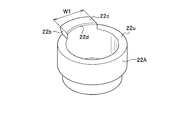
- FIG. 16 is a perspective view showing the configuration of a first modified example of the ball seat 22A in the ball joint J2 of the second embodiment.
- FIG. 17 is a perspective view showing a configuration in which the C ring 64 is placed on the ball seat 22A inserted into the housing 21.
- FIG. 18 is a plan view of a combined configuration of the housing 21, the C ring 64, and the ball seat 22A shown in FIG.
- FIG. 19 is a sectional view taken along line VV of FIG. However, FIG. 19 shows the ball portion 10b on the tip side of the stud portion 10s in the ball seat 22A.
- the ball seat 22A of the first modified example shown in FIG. 16 is different from the above-described ball seat 22 (see FIG. 9) in that the upper end surface 22u of the ball seat 22A is fitted into the gap 64g (FIG. 17) of the C ring 64. This is because the projection 22b to be fitted is provided.
- the convex portion 22b fills the gap 64g of the C ring 64, and thus can be prevented as follows. That is, it is possible to prevent the ball stud 10 from being tilted more than necessary (or improperly) when the stud portion 10s swings, it passes through the gap 64g and tilts to the inner peripheral surface of the housing 21.
- the lateral width w1 of the convex portion 22b shown in FIG. 16 is dimensioned to fit evenly into the gap 64g (FIG. 17) of the C ring 64. Further, the upper end surface 22c of the convex portion 22b has a height lower than the upper end 21c of the housing 21 when the ball seat 22A is incorporated in the housing 21, as shown in FIG.
- the upper end surface 22c of the convex portion 22b is located at a depth position d2 further lower than the penetration depth d1 when the C ring 64 is laser-welded to the housing 21.
- the height is h3.
- the height h3 is the height from the bottom surface of the ball seat 22A to the upper end surface 22c of the convex portion 22b.
- the upper end surface 22c of the convex portion 22b has a height h3 that is separated by a distance that does not melt by laser welding when incorporated in the housing 21. This can prevent melting of the ball seat 22A due to laser welding.
- the convex portion 22b of the ball seat 22A has a tapered surface 22d (see FIGS. 16 and 17) formed on the inner peripheral side thereof so as to be flush with the tapered surface 64c of the C ring 64. ing.
- the tapered surfaces 64c and 22d having an angle ⁇ 2 that satisfies a predetermined swing angle of the ball stud 10 can be formed. With this configuration, the ball stud 10 can be properly swung at a predetermined swing angle.
- FIG. 20 is a perspective view showing a configuration of a second modified example of the ball seat 22B in the ball joint J2 of the second embodiment.
- FIG. 21 is a perspective view showing a configuration in which the C ring 64 is placed on the ball seat 22B inserted into the housing 21.
- 22 is a plan view of a combined configuration of the housing 21, the C ring 64, and the ball seat 22B shown in FIG. 23 is a sectional view taken along line VII-VII of FIG. However, FIG. 23 shows the ball portion 10b on the tip side of the stud portion 10s in the ball seat 22B.
- the ball seat 22B of the second modification shown in FIG. 20 differs from the ball seat 22A of the first modification (see FIG. 16) described above in the shape of the convex portion 22e.
- the outer peripheral surface of the convex portion 22b of the ball seat 22A was in contact with the inner peripheral surface of the housing 21.
- the outer peripheral surface of the convex portion 22e of the ball seat 22B of the second modified example is radially separated from the inner peripheral surface of the housing 21 by a distance d6.
- This separation distance d6 is a distance that the heat of laser welding does not reach the convex portion 22e.
- the gap of this spacing is indicated by an arrow 22g in FIGS. 21 to 23.
- the outer peripheral surface of the convex portion 22e is flush with the outer peripheral surface of the main body of the ball seat 22B, and the radial width of the convex portion 22e is indicated by d5.
- the inner peripheral side surface 21Ab of the housing 21A is formed in a straight shape, and a taper surface 22Cb is provided on the inner peripheral side of the upper end surface 22Ca of the ball seat 22C in the housing 21A.
- a configuration may be used in which a C ring 74 having a shape that abuts on the upper end surface 22Ca and the tapered surface 22Cb without a gap is placed.
- the C ring 74 has a tapered shape in which the inner peripheral side descends along the tapered surface 22Cb of the ball seat 22C, and the tapered lower surface 74e contacts the tapered surface 22Cb of the ball seat 22C. Touching.
- the tapered upper surface 74c has a tapered shape 74f with a steeper angle on the inner peripheral side. This taper shape 74f avoids the interference between the stud portion 10s (stud shaft) and the C ring 74, and preferentially contacts the upper surface 74c.
- the gap between the outer surface 74d of the C ring 74 and the inner peripheral side surface of the housing 21A has a C ring outer diameter of 0.25 mm or less. This gap size is determined by the laser spot diameter at the time of laser welding and the restriction of the welding spot area.
- the C ring 74 can have a centripetal effect. Further, there is no need to process the inner peripheral side surface 21Ab of the housing 21A into a stepped shape via the tapered stepped portion P1 unlike the above-described upper end 21c (FIG. 1) of the housing 21, so that there is an advantage that manufacturing becomes easy. .
- the ball joint J1 of the ball seat fixing structure of the present invention can be applied to a joint part of a robot arm of an industrial robot or a humanoid robot, or a device in which an arm of a shovel car or a crane truck rotates at the joint part.
Abstract
La présente invention concerne un joint à rotule (J1) qui comporte un pivot à rotule (10) dans lequel une partie de bille métallique (10b) est reliée d'un seul tenant à une partie d'extrémité d'une partie de goujon (10s) dont une autre extrémité est reliée à une suspension ou un stabilisateur, un boîtier métallique (21) comportant un espace qui sert de support de manière oscillante et rotative la partie de bille (10b) et qui est ouvert sur un côté, et une feuille de bille de résine (22) intercalée entre le boîtier (21) et la partie de bille (10b). La partie de bille (10b) qui est recouverte par la feuille de bille (22), est renfermée à l'intérieur du boîtier (21). La présente invention est conçue de telle sorte qu'un joint torique (24) établi de manière à faire saillie au-delà d'une partie d'extrémité ouverte (21a) du boîtier est disposé à l'intérieur de la partie d'extrémité ouverte (21a) et au-dessus de la feuille de bille (22), et un coin de la limite entre le joint torique (24) et le boîtier (21) est soudé et fixé par soudage au laser.
Applications Claiming Priority (4)
| Application Number | Priority Date | Filing Date | Title |
|---|---|---|---|
| JP2018200288 | 2018-10-24 | ||
| JP2018-200288 | 2018-10-24 | ||
| JP2019-068768 | 2019-03-29 | ||
| JP2019068768A JP7228449B2 (ja) | 2018-10-24 | 2019-03-29 | ボールジョイントのボールシート固定構造 |
Publications (1)
| Publication Number | Publication Date |
|---|---|
| WO2020085138A1 true WO2020085138A1 (fr) | 2020-04-30 |
Family
ID=70330602
Family Applications (1)
| Application Number | Title | Priority Date | Filing Date |
|---|---|---|---|
| PCT/JP2019/040406 WO2020085138A1 (fr) | 2018-10-24 | 2019-10-15 | Structure de fixation de feuille de bille pour joint à rotule |
Country Status (1)
| Country | Link |
|---|---|
| WO (1) | WO2020085138A1 (fr) |
Citations (6)
| Publication number | Priority date | Publication date | Assignee | Title |
|---|---|---|---|---|
| US4559692A (en) * | 1981-01-23 | 1985-12-24 | Societe Anonyme D.B.A. | Method and apparatus for the manufacture of a ball joint |
| US5564853A (en) * | 1993-07-22 | 1996-10-15 | Dana Corporation | Ball and socket joint assembly |
| DE19756984A1 (de) * | 1997-12-20 | 1999-07-08 | Daimler Chrysler Ag | Kugelgelenk und Verfahren zu seiner Vorspannung |
| US6488436B1 (en) * | 1999-02-04 | 2002-12-03 | Societe Mecanique De Villeurbanne | Ball joint, in particular steering or suspension ball joint for motor vehicles and, method for making a bearing for same |
| DE102004040403A1 (de) * | 2004-08-19 | 2006-03-09 | Zf Friedrichshafen Ag | Kugelgelenk und Verfahren zu dessen Herstellung |
| US9010783B2 (en) * | 2013-05-17 | 2015-04-21 | Benteler Automobiltechnik Gmbh | Ball joint and control arm for a motor vehicle |
-
2019
- 2019-10-15 WO PCT/JP2019/040406 patent/WO2020085138A1/fr active Application Filing
Patent Citations (6)
| Publication number | Priority date | Publication date | Assignee | Title |
|---|---|---|---|---|
| US4559692A (en) * | 1981-01-23 | 1985-12-24 | Societe Anonyme D.B.A. | Method and apparatus for the manufacture of a ball joint |
| US5564853A (en) * | 1993-07-22 | 1996-10-15 | Dana Corporation | Ball and socket joint assembly |
| DE19756984A1 (de) * | 1997-12-20 | 1999-07-08 | Daimler Chrysler Ag | Kugelgelenk und Verfahren zu seiner Vorspannung |
| US6488436B1 (en) * | 1999-02-04 | 2002-12-03 | Societe Mecanique De Villeurbanne | Ball joint, in particular steering or suspension ball joint for motor vehicles and, method for making a bearing for same |
| DE102004040403A1 (de) * | 2004-08-19 | 2006-03-09 | Zf Friedrichshafen Ag | Kugelgelenk und Verfahren zu dessen Herstellung |
| US9010783B2 (en) * | 2013-05-17 | 2015-04-21 | Benteler Automobiltechnik Gmbh | Ball joint and control arm for a motor vehicle |
Similar Documents
| Publication | Publication Date | Title |
|---|---|---|
| EP2816245B1 (fr) | Liaison de stabilisateur et son procédé de fabrication | |
| US20140376989A1 (en) | Connection arrangement for a motor vehicle wheel suspension | |
| US20150190880A1 (en) | Assembly unit with an assembly piece and a welding element, and method of producing the assembly unit | |
| WO2006019145A1 (fr) | Joint à rotule et méthode pour fabriquer celui-ci | |
| US6598778B2 (en) | Aluminum-based metal link for vehicles and a method for producing same | |
| WO2020085138A1 (fr) | Structure de fixation de feuille de bille pour joint à rotule | |
| WO2020203479A1 (fr) | Structure de fixation de siège de rotule pour joint à rotule | |
| JP2020067180A (ja) | ボールジョイントのボールシート固定構造 | |
| JP4323358B2 (ja) | スタビライザの横ずれ防止装置 | |
| JP2008195155A (ja) | トーションビーム式サスペンション | |
| JP2009088309A (ja) | 光半導体装置及びその製造方法と金属キャップ | |
| US7374823B2 (en) | Welded portion constitution and welding method | |
| WO2021010375A1 (fr) | Procédé de fixation de siège de rotule pour joint à rotule, et structure de fixation de siège de rotule | |
| JP4891572B2 (ja) | 電磁弁又は電子膨張弁用の弁体 | |
| JP2015009354A (ja) | ブッシュ取付部具備部品及びその製造方法 | |
| JP7181149B2 (ja) | ボールジョイントのボールシート固定構造及びボールシート固定方法 | |
| JP6650036B2 (ja) | 弁のハウジングアセンブリ及び弁 | |
| JP4560288B2 (ja) | 溶接方法 | |
| JP7398948B2 (ja) | アクスルケース | |
| KR20200020706A (ko) | 차량 부품을 제조하기 위한 방법 및 이 방법에 따라 제조된 차량 부품 | |
| CN214698988U (zh) | 一种新型铝合金传动轴专用复合平衡片 | |
| JP4547384B2 (ja) | 自動車用フルフェイスホイールの製造方法 | |
| KR20180068412A (ko) | 볼조인트의 장착구조 및 그 장착방법 | |
| JP2006168641A (ja) | 自動車のサスペンションアーム | |
| JP2000356238A (ja) | ショックアブソーバの保持構造 |
Legal Events
| Date | Code | Title | Description |
|---|---|---|---|
| 121 | Ep: the epo has been informed by wipo that ep was designated in this application |
Ref document number: 19877306 Country of ref document: EP Kind code of ref document: A1 |
|
| NENP | Non-entry into the national phase |
Ref country code: DE |
|
| 122 | Ep: pct application non-entry in european phase |
Ref document number: 19877306 Country of ref document: EP Kind code of ref document: A1 |