WO2020085101A1 - 画像処理装置と画像処理方法およびプログラム - Google Patents
画像処理装置と画像処理方法およびプログラム Download PDFInfo
- Publication number
- WO2020085101A1 WO2020085101A1 PCT/JP2019/039993 JP2019039993W WO2020085101A1 WO 2020085101 A1 WO2020085101 A1 WO 2020085101A1 JP 2019039993 W JP2019039993 W JP 2019039993W WO 2020085101 A1 WO2020085101 A1 WO 2020085101A1
- Authority
- WO
- WIPO (PCT)
- Prior art keywords
- unit
- image
- attention area
- image processing
- vehicle
- Prior art date
Links
Images


Classifications
-
- G—PHYSICS
- G06—COMPUTING; CALCULATING OR COUNTING
- G06T—IMAGE DATA PROCESSING OR GENERATION, IN GENERAL
- G06T7/00—Image analysis
Definitions
- This technology enables users to draw attention to a subject of interest without damaging the acquired information regarding the image processing device, image processing method, and program.
- Patent Document 1 the entire range or a specified arbitrary range is corrected to an image having no distortion aberration, and the corrected image is displayed on the screen. Further, in Patent Document 2, the front of the vehicle is imaged at a zoom ratio according to the vehicle speed, the presence or absence of a dangerous obstacle in the obtained image is analyzed, and then the result is displayed.
- the purpose of this technology is to provide an image processing device, an image processing method, and a program that can draw the user's attention to a subject of interest without damaging the acquired information.
- the first aspect of this technology is A subject detection unit that performs subject detection using a captured image, An attention area setting unit that sets an attention area for the captured image based on usage state information indicating a usage state of the imaging unit that has acquired the captured image and a subject detection result of the subject detection unit,
- the image processing apparatus includes a conversion processing unit that expands the attention area and reduces other non-attention areas.
- the attention area is set for the captured image based on the usage state information indicating the usage state of the imaging unit that has acquired the captured image and the subject detection result of the subject detection unit.
- the usage state information is information about a change in the relative positional relationship between the moving body provided with the imaging unit and the subject detected by the subject detection unit.
- the usage state information includes a moving speed and a moving direction of a moving body such as a vehicle provided with an imaging unit.
- the attention area setting unit that sets the attention area determines the high-risk area in the captured image based on the usage state information, and sets the image area of the subject located in the high-risk area as the attention area. For example, the attention area setting unit divides the imaging range of the imaging unit into a plurality of areas based on the distance from the imaging unit and the direction with respect to the imaging unit, and determines the degree of risk for each area. The attention area setting unit determines the degree of risk based on the moving speed and moving direction of the moving body. For example, when the moving body is a vehicle and the captured image shows the rear of the vehicle, the attention area setting unit determines the degree of risk based on the speed and the backward direction when the vehicle is moving backward. In addition, the attention area setting unit may use the distance to the area or the subject detection result to determine the degree of risk.
- the conversion processing unit enlarges the attention area set by the attention area setting unit and reduces other non-attention areas so that the information acquired by the imaging unit is included in the image after the conversion processing. Further, the conversion processing unit may adjust the enlargement ratio of the attention area according to the usage state information or the degree of danger.
- the second aspect of this technology is Performing subject detection in the subject detection unit using the captured image, Setting an attention area in the attention area with the attention area setting unit based on the use state information indicating the use state of the image capturing unit that has acquired the captured image and the subject detection result of the subject detecting unit;
- An image processing method including enlarging the attention area and reducing other non-attention areas by a conversion processing unit.
- the third aspect of this technology is A program that causes a computer to execute processing of a captured image, A procedure for subject detection using a captured image, A procedure of setting a region of interest for the captured image based on the use state information indicating the use state of the image capturing unit that has acquired the captured image and the detection result of the subject detection; And a procedure for enlarging the attention area and reducing other non-attention areas in the program.
- the program of the present technology is, for example, a storage medium or a communication medium provided in a computer-readable format to a general-purpose computer capable of executing various program codes, for example, a storage medium such as an optical disk, a magnetic disk, or a semiconductor memory. It is a program that can be provided by a medium or a communication medium such as a network. By providing such a program in a computer-readable format, processing according to the program is realized on the computer.
- the attention area is set for the captured image based on the use state information indicating the use state of the image capturing unit that has acquired the captured image and the detection result of subject detection using the captured image.
- a conversion process of enlarging and reducing other non-target areas is performed. Therefore, by displaying the image after the conversion processing, it is possible to call the user's attention to the subject of interest without damaging the acquired information.
- FIG. 6 is a flowchart illustrating the operation of the image processing unit according to the first embodiment. It is a figure showing an example of operation of an image processing part. It is a figure which shows the structure of the 2nd form of an image processing part. 9 is a flowchart illustrating an operation of the image processing unit according to the second embodiment.
- It is a block diagram showing an example of a schematic structure of a vehicle control system. It is a figure which shows an example of the installation position of an imaging part and a vehicle exterior information detection part. It is a figure showing an example of division of a field. It is a figure for demonstrating calculation of a risk point. It is a figure for demonstrating the distance point Pb and the guideline point Pc. It is a figure showing an example of calculation of a risk point. It is a figure for explaining an enlargement / reduction processing.
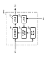
- FIG. 1 illustrates the configuration of an imaging system using the image processing device of the present technology.
- the imaging system 10 includes an imaging unit 20, an image processing unit 30, a usage state information generation unit 40, and a display unit 50.
- the image pickup section 20 has an image pickup lens 21 and an image sensor section 22.
- the imaging lens 21 uses a wide-angle lens so that a wide range can be imaged.
- the imaging lens 21 forms a subject optical image on the imaging surface of the image sensor unit 22 in the imaging unit 20.
- the image sensor unit 22 is configured by using, for example, a CMOS (Complementary Metal Oxide Semiconductor) image sensor or a CCD (Charge Coupled Device) image sensor.
- the image sensor unit 22 generates an image signal according to the subject optical image and outputs the image signal to the image processing unit 30.
- CMOS Complementary Metal Oxide Semiconductor
- CCD Charge Coupled Device
- the image processing unit 30 sets the attention area according to the usage state information and the like generated by the usage state information generation unit 40.
- the image processing unit 30 displays an image of interest in the captured image acquired by the image capturing unit 20 as a magnified display in which the distortion aberration is corrected, and a non-attention region other than the attention region as a reduced display in which the distortion aberration is corrected.
- a signal is generated and output to the display unit 50.
- the usage status information generation unit 40 generates, as usage status information, information regarding a change in the relative positional relationship between the moving body provided with the imaging unit 20 and the subject detected by the subject detection unit 32. For example, when the imaging direction of the imaging unit 20 (the optical axis direction of the imaging lens 21) is the moving direction of the moving body, the usage state information generation unit 40 uses the information indicating the moving direction and the moving speed of the moving body. Generate as information.
- the display unit 50 Based on the image signal generated by the image processing unit 30, the display unit 50 displays an image in which the attention area is corrected for distortion and enlarged, and the non-attention area is corrected for distortion and reduced in size. .
- FIG. 2 shows the configuration of the first form of the image processing unit.
- the image processing unit 30-1 includes a distortion correction unit 31, a subject detection unit 32, an input unit 33, an attention area setting unit 34, a conversion processing unit 35, and an output unit 37.
- the distortion correction unit 31 corrects the distortion of the captured image acquired by the imaging unit 20.
- the distortion correction unit 31 corrects the distortion aberration generated in the captured image based on the optical characteristic information of the image pickup lens 21 used in the image pickup unit 20, and outputs the corrected image signal to the subject detection unit 32 and the conversion processing unit. Output to 35.
- the subject detection unit 32 performs recognition processing using the image signal after distortion correction supplied from the distortion correction unit 31 and detects what kind of subject is a subject located within the imaging range.
- the subject detection unit 32 outputs the detection result of the subject to the attention area setting unit 34.
- the input unit 33 acquires the usage status information from the usage status information generation unit 40 and outputs it to the attention area setting unit 34.
- the attention area setting unit 34 sets the attention area for the captured image based on the usage state information indicating the usage state of the imaging unit 20 that has acquired the captured image and the subject detection result of the subject detection unit 32.
- the attention area setting unit 34 determines a highly dangerous area in the captured image based on the usage state information.
- the risk level indicates the risk of collision or contact with a moving body provided with the imaging unit 20, and the high-risk area indicates that a subject located in this area is in collision or contact with the moving body. It indicates that the area is highly likely. For example, when the moving direction of the moving body is indicated by the use state information, the attention area setting unit 34 has a high risk of an area having a predetermined width based on the position of the moving direction in the captured image acquired by the imaging unit 20.
- the image area of the subject located in the area with high risk is set as the attention area.
- the moving direction and the moving speed of the moving body are indicated in the usage state information, a wide range in the moving direction increases as the moving speed increases with reference to the position of the moving direction in the captured image acquired by the imaging unit 20. May be set as the high-risk area, and the image area of the subject located in the high-risk area may be set as the attention area.
- the attention area setting unit 34 may determine an area having a high degree of risk by using the distance from the imaging unit 20 or the subject detection result.
- the attention area setting unit 34 outputs attention area information indicating the set attention area to the conversion processing unit 35.
- the conversion processing unit 35 uses the image signal after distortion correction supplied from the distortion correction unit 31 to perform enlargement processing of the attention area and reduction processing of the non-attention area.
- the conversion processing unit 35 enlarges the image of the attention area set by the attention area setting unit 34. Furthermore, since the image size increases by enlarging the attention area, the conversion processing unit 35 reduces the non-attention area so that the information acquired by the imaging unit 20 is included in the image after the conversion processing.
- the conversion processing unit 35 outputs the image signal subjected to the enlargement processing and the reduction processing to the output unit 37.
- the output unit 37 performs resolution conversion that converts the image signal that has been subjected to distortion correction and scaling to an image signal of the display resolution of the display unit 50, and the image signal after the resolution conversion is in a format that can be input to the display unit 50. Output as a signal.
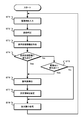
- FIG. 3 is a flowchart illustrating the operation of the image processing unit according to the first embodiment.
- the image processing unit inputs a captured image.
- the image processing unit 30-1 inputs the image signal of the captured image acquired by the imaging unit 20 and proceeds to step ST2.
- the image processing unit performs distortion correction in step ST2.
- the image processing unit 30-1 corrects the distortion aberration generated in the captured image by the imaging lens 21 of the imaging unit 20 and proceeds to step ST3.
- step ST3 the image processing unit acquires usage status information.
- the image processing unit 30-1 acquires the usage status information generated by the usage status information generation unit 40 and proceeds to step ST4.
- step ST4 the image processing unit determines whether the usage status information has changed.
- the image processing unit 30-1 determines that the usage status information has changed and proceeds to step ST6. If they match, it is determined that there is no change and the process proceeds to step ST5.
- step ST5 the image processing unit determines whether or not the captured image has changed.
- the image processing unit 30-1 determines that the imaged image has changed, proceeds to step ST6, and matches. In this case, it is determined that there is no change, and the process proceeds to step ST8.
- step ST6 the image processing unit detects the subject.
- the image processing unit 30-1 detects a subject using the captured image input in step ST1 and proceeds to step ST7.
- the image processing unit sets a region of interest in step ST7.
- the image processing unit 30-1 sets the attention area in the captured image based on the use state information acquired in step ST3 and the subject detection result obtained in step ST6. For example, when the imaging unit 20 is fixed to the moving body with the moving direction of the moving body as the imaging direction as described above, the image processing unit 30-1 includes a subject located in the moving direction of the moving body. A rectangular area is set as the attention area.
- the image processing unit 30-1 sets a region of interest and proceeds to step ST8.
- step ST8 the image processing unit performs enlargement / reduction processing.
- the image processing unit 30-1 enlarges the attention area set in step ST7 at a predetermined enlargement ratio. Further, since the image size of the captured image increases when the attention area is enlarged, the non-attention area is reduced so that the information acquired by the imaging unit is included in the image after the conversion process.
- the image processing unit 30-1 performs the enlargement / reduction processing in the horizontal direction based on the equation (1), and the enlargement / reduction processing in the vertical direction based on the equation (2), for example.
- the horizontal expansion rate of the attention area is “Kht> 1”
- the horizontal expansion rate of the non-attention area is “Khe ⁇ 1”
- the vertical expansion rate of the attention area is “Kvt> 1.”
- the enlargement ratio of the area in the vertical direction is “Kve ⁇ 1”.
- Total number of pixels in the horizontal direction number of pixels in the horizontal direction of the region of interest x Kht + Number of horizontal pixels in non-target area x Khe (1)
- Total number of pixels in the vertical direction number of pixels in the vertical direction of the region of interest x Kvt + Number of vertical pixels in non-target area x Kve (2)
- the image processing unit 30-1 outputs the image signal of the display image in which the attention area is enlarged and the non-attention area is reduced to the display unit 50 and returns to step ST1.
- FIG. 4 shows an operation example of the image processing unit.
- FIG. 4A illustrates an imaged image after distortion aberration correction.
- the subject (subject) OBa located in the moving direction has a smaller display size than other subjects OBb, and is less noticeable.
- the rectangular area including the object OBa located in the moving direction of the moving body is set as the attention area AT to perform the enlargement processing of the attention area, and the object OBa is enlarged and displayed as shown in FIG. 4B. Then, it becomes possible to call the user's attention to the subject OBa.
- the image processing unit 30-1 performs enlargement processing of the attention area and reduction processing of other non-attention areas so that the information acquired by the imaging unit is included in the image after the conversion processing.
- the subject OBa is enlarged and displayed, and the user's attention can be called to the subject OBa. Further, it is possible to recognize the subject OBb in the non-attention area.
- a captured image can be presented so that the user's attention can be drawn to a subject of interest without damaging the information acquired by the image capturing unit 20.
- FIG. 5 shows the configuration of the second embodiment of the image processing unit.
- the image processing unit 30-2 includes a subject detection unit 32, an input unit 33, a attention area setting unit 34, a conversion processing unit 36, and an output unit 37.
- the subject detection unit 32 performs recognition processing using the image signal after distortion correction supplied from the distortion correction unit 31 and detects a subject located within the imaging range.
- the subject detection unit 32 outputs the detection result of the subject to the attention area setting unit 34.
- the input unit 33 acquires the usage status information from the usage status information generation unit 40 and outputs it to the attention area setting unit 34.
- the attention area setting unit 34 determines the captured image based on the usage state information indicating the usage state of the imaging unit 20 that has acquired the captured image and the subject detection result of the subject detection unit 32. Set the area of interest.
- the attention area setting unit 34 outputs attention area information indicating the set attention area to the conversion processing unit 36.
- the conversion processing unit 36 uses the image signal of the captured image obtained by the imaging unit 20 to perform distortion aberration correction processing, attention area enlargement processing, and non-attention area reduction processing.
- the conversion processing unit 36 corrects the distortion aberration occurring in the captured image based on the optical characteristic information of the imaging lens 21 used in the imaging unit 20. Further, the conversion processing unit 36 enlarges the image of the attention area set by the attention area setting unit 34. Further, the conversion processing unit 36 reduces the non-focused region so that the information obtained by the imaging unit 20 is included in the image after the conversion process because the image size increases by enlarging the focused region.
- the conversion processing unit 36 uses the image signal of the captured image acquired by the image capturing unit 20 to perform coordinate conversion for generating an image signal in which the distortion aberration is corrected and the image is scaled up and down, and after the conversion process is performed.
- the image signal is output to the output unit 37.
- the output unit 37 performs resolution conversion that converts the image signal that has been subjected to distortion correction and scaling to an image signal of the display resolution of the display unit 50, and the image signal after the resolution conversion is in a format that can be input to the display unit 50. Output as a signal.
- FIG. 6 is a flowchart showing the operation of the second embodiment of the image processing unit.
- the image processing unit inputs a captured image.
- the image processing unit 30-2 inputs the image signal of the captured image acquired by the imaging unit 20 and proceeds to step ST12.
- step ST12 the image processing unit acquires usage status information.
- the image processing unit 30-2 acquires the usage status information generated by the usage status information generation unit 40 and proceeds to step ST13.
- step ST13 the image processing unit determines whether the usage status information has changed. If the usage status information acquired in step ST12 is different from the usage status information acquired in the previous processing in step ST12, the image processing unit 30-2 determines that the usage status information has changed and proceeds to step ST15. If they match, it is determined that there is no change and the process proceeds to step ST14.
- step ST14 the image processing unit determines whether the captured image has changed.
- the image processing unit 30-2 determines that the imaged image has changed, proceeds to step ST15, and matches. In this case, it is determined that there is no change, and the process proceeds to step ST17.
- step ST15 the image processing unit detects the subject.
- the image processing unit 30-2 performs subject detection using the captured image input in step ST1 and proceeds to step ST16.
- the image processing unit sets a region of interest in step ST16.
- the image processing unit 30-2 sets the attention area in the captured image based on the use state information acquired in step ST12 and the subject detection result obtained in step ST15. For example, when the imaging unit 20 is fixed to the moving body with the moving direction of the moving body as the imaging direction as described above, the image processing unit 30-2 includes a subject located in the moving direction of the moving body. A rectangular area is set as the attention area.
- the image processing unit 30-2 sets a region of interest and proceeds to step ST17.
- the image processing unit performs conversion processing in step ST17.
- the image processing unit 30-2 performs, as conversion processes, a process of correcting the distortion aberration generated in the captured image by the imaging lens 21 of the image capturing unit 20 and a process of enlarging the attention area set in step ST16 at a predetermined enlargement ratio. Then, the reduction processing of the non-attention area is performed according to the enlargement of the attention area.
- the image processing unit 30-2 outputs the image signal of the display image in which the distortion is corrected, the attention area is enlarged and the non-attention area is reduced, to the display unit 50, and the process returns to step ST11.
- the captured image so that the user's attention can be drawn to the subject of interest without damaging the information acquired by the image capturing unit 20.
- the attention area can be enlarged, and the non-attention area can be reduced by the conversion processing, the display image can be generated more efficiently than in the first embodiment.
- the subject detection unit 32 detects the type of subject by performing the recognition process using the captured images, but detects the movement of the subject using the plurality of captured images in time order. May be.
- the attention area setting unit 34 may use the movement of the subject to set the attention area. For example, an area where the moving direction of the moving object and the moving direction of the subject intersect each other is set as a high-risk area, and an image area of the subject that moves so as to be located in the high-risk area is set as the attention area.
- the movement of the subject may be detected based on the optical flow calculated using the imaged image acquired by the image capturing unit 20. In this way, if the attention area is set in consideration of the movement of the subject, it is possible to present a captured image that can call the user's attention to the subject that has caused a movement such as collision or contact with a moving body.
- the conversion processing unit 35 may adjust the enlargement ratio of the attention area according to the usage state information or according to the risk degree of the attention area.
- the conversion processing unit 35 adjusts the enlargement ratio of the attention area according to, for example, the moving speed of the moving body indicated by the use state information, and increases the enlargement ratio as the moving speed increases. By adjusting the enlargement ratio in this way, when the moving speed is high, the subject to be noted is displayed in a large size even if it is far, so that the user can be alerted to the subject to be noted.
- the conversion processing unit 35 adjusts the enlargement ratio of the attention area according to the risk degree of the attention area, and increases the enlargement ratio as the danger degree increases.
- the user can determine that the risk is high depending on the display size of the subject, and when the risk is high and the subject is displayed large, for example, the moving body is quickly stopped. It becomes possible to appropriately perform the risk avoidance operation such as.
- the attention area is a high risk area. It is not limited to the image area of the subject located at.
- the speed of the vehicle equipped with the imaging unit is used as the usage state information, and the object recognition result and the motion detection result are used as the object detection result.
- the attention area setting unit sets, as the attention area, an image area of another vehicle approaching the vehicle equipped with the imaging unit at a speed higher than a predetermined speed, for example. Further, the enlargement ratio may be increased as the approaching speed becomes higher.
- the technology according to the present disclosure can be applied to various products.
- the technology according to the present disclosure is applicable to any type of movement such as an automobile, an electric vehicle, a hybrid electric vehicle, a motorcycle, a bicycle, a personal mobility, an airplane, a drone, a ship, a robot, a construction machine, and an agricultural machine (tractor). It may be realized as a device mounted on the body.
- FIG. 7 is a block diagram showing a schematic configuration example of a vehicle control system 7000 which is an example of a mobile body control system to which the technology according to the present disclosure can be applied.
- the vehicle control system 7000 includes a plurality of electronic control units connected via a communication network 7010.
- the vehicle control system 7000 includes a drive system control unit 7100, a body system control unit 7200, a battery control unit 7300, a vehicle exterior information detection unit 7400, a vehicle interior information detection unit 7500, and an integrated control unit 7600. .
- the communication network 7010 connecting these plural control units complies with any standard such as CAN (Controller Area Network), LIN (Local Interconnect Network), LAN (Local Area Network) or FlexRay (registered trademark). It may be an in-vehicle communication network.
- CAN Controller Area Network
- LIN Local Interconnect Network
- LAN Local Area Network
- FlexRay registered trademark
- Each control unit includes a microcomputer that performs arithmetic processing according to various programs, a storage unit that stores a program executed by the microcomputer or parameters used for various arithmetic operations, and a drive circuit that drives various controlled devices. Equipped with.
- Each control unit is equipped with a network I / F for communicating with other control units via the communication network 7010, and is also used for wired or wireless communication with devices or sensors inside or outside the vehicle. A communication I / F for performing communication is provided. In FIG.
- a microcomputer 7610 a general-purpose communication I / F 7620, a dedicated communication I / F 7630, a positioning unit 7640, a beacon receiving unit 7650, an in-vehicle device I / F 7660, an audio image output unit 7670, An in-vehicle network I / F 7680 and a storage unit 7690 are illustrated.
- the other control units also include a microcomputer, a communication I / F, a storage unit, and the like.
- the drive system control unit 7100 controls the operation of devices related to the drive system of the vehicle according to various programs.
- the drive system control unit 7100 includes a drive force generation device for generating a drive force of a vehicle such as an internal combustion engine or a drive motor, a drive force transmission mechanism for transmitting the drive force to wheels, and a steering angle of the vehicle. It functions as a steering mechanism for adjusting and a control device such as a braking device for generating a braking force of the vehicle.
- the drive system control unit 7100 may have a function as a control device such as ABS (Antilock Brake System) or ESC (Electronic Stability Control).
- a vehicle state detection unit 7110 is connected to the drive system control unit 7100.
- the vehicle state detection unit 7110 includes, for example, a gyro sensor that detects the angular velocity of the shaft rotational movement of the vehicle body, an acceleration sensor that detects the acceleration of the vehicle, or an accelerator pedal operation amount, a brake pedal operation amount, or a steering wheel steering operation. At least one of the sensors for detecting the angle, the engine speed, the wheel rotation speed, etc. is included.
- the drive system control unit 7100 performs arithmetic processing using the signal input from the vehicle state detection unit 7110 to control the internal combustion engine, drive motor, electric power steering device, brake device, or the like.
- the body system control unit 7200 controls the operation of various devices mounted on the vehicle body according to various programs.
- the body system control unit 7200 functions as a keyless entry system, a smart key system, a power window device, or a control device for various lamps such as a head lamp, a back lamp, a brake lamp, a winker, or a fog lamp.
- the body system control unit 7200 may receive radio waves or signals of various switches transmitted from a portable device that substitutes for a key.
- the body system control unit 7200 receives the input of these radio waves or signals and controls the vehicle door lock device, the power window device, the lamp, and the like.
- the battery control unit 7300 controls the secondary battery 7310 that is the power supply source of the drive motor according to various programs. For example, to the battery control unit 7300, information such as the battery temperature, the battery output voltage, or the remaining capacity of the battery is input from the battery device including the secondary battery 7310. The battery control unit 7300 performs arithmetic processing using these signals to control the temperature adjustment of the secondary battery 7310 or the cooling device or the like provided in the battery device.
- the exterior information detection unit 7400 detects information outside the vehicle equipped with the vehicle control system 7000.
- the image capturing unit 7410 and the vehicle exterior information detection unit 7420 is connected to the vehicle exterior information detection unit 7400.
- the imaging unit 7410 includes at least one of a ToF (Time Of Flight) camera, a stereo camera, a monocular camera, an infrared camera, and other cameras.
- the outside-vehicle information detection unit 7420 detects, for example, an environment sensor for detecting current weather or weather, or another vehicle around the vehicle equipped with the vehicle control system 7000, an obstacle, a pedestrian, or the like. At least one of the ambient information detection sensors of.
- the environment sensor may be, for example, at least one of a raindrop sensor that detects rainy weather, a fog sensor that detects fog, a sunshine sensor that detects the degree of sunshine, and a snow sensor that detects snowfall.
- the ambient information detection sensor may be at least one of an ultrasonic sensor, a radar device, and a LIDAR (Light Detection and Ranging, Laser Imaging Detection and Ranging) device.
- the imaging unit 7410 and the vehicle exterior information detection unit 7420 may be provided as independent sensors or devices, or may be provided as a device in which a plurality of sensors or devices are integrated.
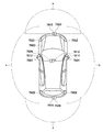
- FIG. 8 shows an example of installation positions of the image pickup unit 7410 and the vehicle exterior information detection unit 7420.
- the imaging units 7910, 7912, 7914, 7916, 7918 are provided at at least one of the front nose of the vehicle 7900, the side mirrors, the rear bumper, the back door, and the upper part of the windshield inside the vehicle.
- the image capturing unit 7910 provided on the front nose and the image capturing unit 7918 provided on the upper part of the windshield in the vehicle interior mainly acquire an image in front of the vehicle 7900.
- the imaging units 7912 and 7914 provided in the side mirrors mainly acquire images of the side of the vehicle 7900.
- the imaging unit 7916 provided in the rear bumper or the back door mainly acquires an image of the rear of the vehicle 7900.
- the imaging unit 7918 provided on the upper part of the windshield in the vehicle interior is mainly used for detecting a preceding vehicle, a pedestrian, an obstacle, a traffic signal, a traffic sign, a lane, or the like.
- FIG. 8 shows an example of the shooting ranges of the respective image pickup units 7910, 7912, 7914, 7916.
- the imaging range a indicates the imaging range of the imaging unit 7910 provided on the front nose
- the imaging ranges b and c indicate the imaging ranges of the imaging units 7912 and 7914 provided on the side mirrors
- the imaging range d is The imaging range of the imaging part 7916 provided in the rear bumper or the back door is shown. For example, by overlaying the image data captured by the image capturing units 7910, 7912, 7914, and 7916, a bird's-eye view image of the vehicle 7900 viewed from above can be obtained.
- the vehicle exterior information detection units 7920, 7922, 7924, 7926, 7928, 7930 provided on the front, rear, sides, corners of the vehicle 7900 and on the upper part of the windshield inside the vehicle may be ultrasonic sensors or radar devices, for example.
- the vehicle exterior information detection units 7920, 7926, 7930 provided on the front nose, rear bumper, back door, and upper windshield of the vehicle 7900 may be, for example, LIDAR devices.
- These vehicle exterior information detection units 7920 to 7930 are mainly used for detecting a preceding vehicle, a pedestrian, an obstacle, or the like.
- the vehicle exterior information detection unit 7400 causes the image capturing unit 7410 to capture an image of the vehicle exterior and receives the captured image data. Further, the vehicle exterior information detection unit 7400 receives detection information from the vehicle exterior information detection unit 7420 connected thereto. When the vehicle exterior information detection unit 7420 is an ultrasonic sensor, a radar device, or a LIDAR device, the vehicle exterior information detection unit 7400 transmits ultrasonic waves, electromagnetic waves, or the like, and receives information on the received reflected waves.
- the vehicle exterior information detection unit 7400 may perform object detection processing or distance detection processing such as people, vehicles, obstacles, signs, or characters on the road surface based on the received information.
- the vehicle exterior information detection unit 7400 may perform environment recognition processing for recognizing rainfall, fog, road surface conditions, or the like based on the received information.
- the vehicle exterior information detection unit 7400 may calculate the distance to an object outside the vehicle based on the received information.
- the vehicle exterior information detection unit 7400 may also perform image recognition processing or distance detection processing for recognizing people, vehicles, obstacles, signs, characters on the road surface, or the like based on the received image data.
- the vehicle exterior information detection unit 7400 performs processing such as distortion correction or position adjustment on the received image data, combines the image data captured by different image capturing units 7410, and generates an overhead image or a panoramic image. Good.
- the vehicle exterior information detection unit 7400 may perform viewpoint conversion processing using image data captured by different image capturing units 7410.
- the in-vehicle information detection unit 7500 detects in-vehicle information.
- a driver state detection unit 7510 that detects the state of the driver is connected.
- the driver state detection unit 7510 may include a camera that captures an image of the driver, a biometric sensor that detects biometric information of the driver, a microphone that collects voice in the vehicle interior, and the like.
- the biometric sensor is provided on, for example, a seat surface or a steering wheel, and detects biometric information of an occupant sitting on a seat or a driver who holds the steering wheel.
- the in-vehicle information detection unit 7500 may calculate the degree of tiredness or concentration of the driver based on the detection information input from the driver state detection unit 7510, and determines whether the driver is asleep. You may.
- the in-vehicle information detection unit 7500 may perform processing such as noise canceling processing on the collected audio signal.
- the integrated control unit 7600 controls overall operations in the vehicle control system 7000 according to various programs.
- An input unit 7800 is connected to the integrated control unit 7600.
- the input unit 7800 is realized by, for example, a device such as a touch panel, a button, a microphone, a switch or a lever that can be input and operated by a passenger. Data obtained by voice recognition of voice input by a microphone may be input to the integrated control unit 7600.
- the input unit 7800 may be, for example, a remote control device that uses infrared rays or other radio waves, or may be an external connection device such as a mobile phone or a PDA (Personal Digital Assistant) that supports the operation of the vehicle control system 7000. May be.
- the input unit 7800 may be, for example, a camera, in which case the passenger can input information by gesture. Alternatively, data obtained by detecting the movement of the wearable device worn by the passenger may be input. Furthermore, the input unit 7800 may include, for example, an input control circuit that generates an input signal based on information input by a passenger or the like using the input unit 7800 and outputs the input signal to the integrated control unit 7600. A passenger or the like operates the input unit 7800 to input various data or instruct a processing operation to the vehicle control system 7000.
- the storage unit 7690 may include a ROM (Read Only Memory) that stores various programs executed by the microcomputer, and a RAM (Random Access Memory) that stores various parameters, calculation results, sensor values, and the like.
- the storage unit 7690 may be realized by a magnetic storage device such as an HDD (Hard Disc Drive), a semiconductor storage device, an optical storage device, a magneto-optical storage device, or the like.
- the general-purpose communication I / F 7620 is a general-purpose communication I / F that mediates communication with various devices existing in the external environment 7750.
- the general-purpose communication I / F 7620 is a cellular communication protocol such as GSM (registered trademark) (Global System of Mobile communications), WiMAX (registered trademark), LTE (registered trademark) (Long Term Evolution), or LTE-A (LTE-Advanced).
- GSM Global System of Mobile communications
- WiMAX registered trademark
- LTE registered trademark
- LTE-A Long Term Evolution
- LTE-A Long Term Evolution-Advanced
- another wireless communication protocol such as a wireless LAN (also referred to as Wi-Fi (registered trademark)) or Bluetooth (registered trademark) may be implemented.
- the general-purpose communication I / F 7620 is connected to a device (for example, an application server or a control server) existing on an external network (for example, the Internet, a cloud network, or a network unique to an operator) via a base station or an access point, for example. You may. Further, the general-purpose communication I / F 7620 is, for example, using P2P (Peer To Peer) technology, a terminal existing in the vicinity of the vehicle (for example, a driver, a pedestrian or a shop terminal, or an MTC (Machine Type Communication) terminal). May be connected with.
- P2P Peer To Peer
- a terminal existing in the vicinity of the vehicle for example, a driver, a pedestrian or a shop terminal, or an MTC (Machine Type Communication) terminal. May be connected with.
- the dedicated communication I / F 7630 is a communication I / F that supports a communication protocol formulated for use in a vehicle.
- the dedicated communication I / F 7630 uses a standard protocol such as WAVE (Wireless Access in Vehicle Environment), DSRC (Dedicated Short Range Communications), or a cellular communication protocol, which is a combination of a lower layer IEEE 802.11p and an upper layer IEEE 1609, for example. May be implemented.
- the dedicated communication I / F 7630 is typically a vehicle-to-vehicle communication, a vehicle-to-infrastructure communication, a vehicle-to-home communication and a vehicle-to-pedestrian communication. ) Perform V2X communications, a concept that includes one or more of the communications.
- the positioning unit 7640 receives, for example, a GNSS signal from a GNSS (Global Navigation Satellite System) satellite (for example, a GPS signal from a GPS (Global Positioning System) satellite) to perform positioning, and the latitude, longitude, and altitude of the vehicle. Generate position information including. Note that the positioning unit 7640 may specify the current position by exchanging signals with the wireless access point, or may acquire position information from a terminal such as a mobile phone, PHS, or smartphone having a positioning function.
- GNSS Global Navigation Satellite System
- GPS Global Positioning System
- the beacon receiving unit 7650 receives, for example, a radio wave or an electromagnetic wave transmitted from a wireless station or the like installed on the road, and acquires information such as the current position, traffic jam, traffic closure, or required time.
- the function of beacon reception unit 7650 may be included in dedicated communication I / F 7630 described above.
- the in-vehicle device I / F 7660 is a communication interface that mediates a connection between the microcomputer 7610 and various in-vehicle devices 7760 existing in the vehicle.
- the in-vehicle device I / F 7660 may establish a wireless connection using a wireless communication protocol such as a wireless LAN, Bluetooth (registered trademark), NFC (Near Field Communication) or WUSB (Wireless USB).
- a wireless communication protocol such as a wireless LAN, Bluetooth (registered trademark), NFC (Near Field Communication) or WUSB (Wireless USB).
- the in-vehicle device I / F 7660 can be connected to a USB (Universal Serial Bus), HDMI (registered trademark) (High-Definition Multimedia Interface, or MHL (Mobile High) via a connection terminal (and a cable if necessary) not shown. -Definition Link) etc.
- the in-vehicle device 7760 includes, for example, at least one of a mobile device or a wearable device that the passenger has, or an information device that is carried in or attached to the vehicle.
- the in-vehicle device 7760 may include a navigation device that searches for a route to an arbitrary destination.
- the in-vehicle device I / F 7660 is a control signal between the in-vehicle device 7760 and the in-vehicle device 7760. Or exchange data signals.
- the in-vehicle network I / F 7680 is an interface that mediates communication between the microcomputer 7610 and the communication network 7010.
- the vehicle-mounted network I / F 7680 transmits and receives signals and the like according to a predetermined protocol supported by the communication network 7010.
- the microcomputer 7610 of the integrated control unit 7600 passes through at least one of the general-purpose communication I / F 7620, the dedicated communication I / F 7630, the positioning unit 7640, the beacon receiving unit 7650, the in-vehicle device I / F 7660, and the in-vehicle network I / F 7680.
- the vehicle control system 7000 is controlled according to various programs based on the information acquired by the above. For example, the microcomputer 7610 calculates the control target value of the driving force generation device, the steering mechanism or the braking device based on the acquired information on the inside and outside of the vehicle, and outputs the control command to the drive system control unit 7100. Good.
- the microcomputer 7610 realizes the functions of ADAS (Advanced Driver Assistance System) including avoidance or impact mitigation of a vehicle, follow-up traveling based on an inter-vehicle distance, vehicle speed maintenance traveling, a vehicle collision warning, or a vehicle lane departure warning. You may perform the cooperative control aiming at.
- the microcomputer 7610 controls the driving force generation device, the steering mechanism, the braking device, and the like based on the acquired information about the surroundings of the vehicle, so that the microcomputer 7610 automatically travels independently of the driver's operation. You may perform the cooperative control for the purpose of driving etc.
- ADAS Advanced Driver Assistance System
- a general-purpose communication I / F 7620 a dedicated communication I / F 7630, a positioning unit 7640, a beacon receiving unit 7650, an in-vehicle device I / F 7660, and an in-vehicle network I / F 7680.
- the microcomputer 7610 may predict a danger such as a vehicle collision, a proximity of a pedestrian or the like, or an approach to a closed road by a vehicle based on the acquired information, and may generate a warning signal.
- the warning signal may be, for example, a signal for generating a warning sound or turning on a warning lamp.
- the voice image output unit 7670 transmits an output signal of at least one of a voice and an image to an output device capable of visually or audibly notifying information to a passenger of the vehicle or the outside of the vehicle.
- an audio speaker 7710, a display unit 7720, and an instrument panel 7730 are illustrated as output devices.
- the display unit 7720 may include at least one of an onboard display and a head-up display, for example.
- the display unit 7720 may have an AR (Augmented Reality) display function.
- the output device may be a device other than these devices, such as headphones, a wearable device such as a glasses-type display worn by a passenger, a projector, or a lamp.
- the display device displays results obtained by various processes performed by the microcomputer 7610 or information received from another control unit in various formats such as text, images, tables, and graphs. Display visually.
- the audio output device converts an audio signal composed of reproduced audio data, acoustic data, or the like into an analog signal and outputs it audibly.
- control units connected via the communication network 7010 may be integrated as one control unit.
- each control unit may be composed of a plurality of control units.
- the vehicle control system 7000 may include another control unit not shown.
- some or all of the functions of one of the control units may be given to another control unit. That is, as long as information is transmitted and received via the communication network 7010, the predetermined arithmetic processing may be performed by any control unit.
- a sensor or device connected to one of the control units may be connected to another control unit, and a plurality of control units may send and receive detection information to and from each other via the communication network 7010. .
- the computer program for realizing each function of the information processing apparatus according to the present embodiment described with reference to FIG. 7 can be installed in any control unit or the like. It is also possible to provide a computer-readable recording medium in which such a computer program is stored.
- the recording medium is, for example, a magnetic disk, an optical disk, a magneto-optical disk, a flash memory, or the like. Further, the above computer program may be distributed, for example, via a network without using a recording medium.
- the image processing unit 30 can be applied to the integrated control unit 7600 shown in FIG. 7. Further, the image pickup unit 7916 of FIG. 8 is used as the image pickup unit 20, the vehicle state detection unit 7110 of FIG. 7 is used as the usage state information generation unit 40, and the display unit 7720 of FIG. 7 is used as the display unit 50.
- the usage state information generation unit 40 when applied to the vehicle control system, the usage state information generation unit 40 generates the information indicating the vehicle speed and the steering angle as the usage state information. Further, the image processing unit 30 may use the use state information to calculate, for example, a risk point indicating a risk level, and set the attention area based on the calculated risk point.
- the attention area setting unit 34 divides the rear of the vehicle CR equipped with the vehicle control system into a plurality of areas, for example, and calculates a risk point for each area. The area is divided based on the distance from the imaging unit and the direction with respect to the imaging unit.
- FIG. 9 shows an example of area division, and shows a case where the area behind the vehicle CR is divided into areas BA0 to BA9 based on the distance and direction.
- FIG. 10 is a diagram for explaining calculation of risk points.
- the risk point PT is, for example, the multiplication result of the vehicle speed point Pa, the distance point Pb, the guideline point Pc, and the civilization point Pd.
- the vehicle speed point Pa is a point corresponding to the vehicle speed, and the point value increases as the vehicle speed increases.
- FIG. 11 is a diagram for explaining the distance point Pb and the guideline point Pc.
- the distance point Pb is a point corresponding to the distance LA to the area.
- the image processing unit 30 increases the point value as the distance LA to the area becomes shorter.
- the guideline point Pc is a point according to whether or not the area is included in the vehicle passing scheduled area AMF when the vehicle CR moves in the moving direction MF determined based on the steering angle.
- the image processing unit 30 increases the point value when the area is within the vehicle passage scheduled area AMF.
- the personality point Pd is a point corresponding to the detected civilization of the subject.
- the image processing unit 30 increases the point value when it is determined that the detected subject is a person, and decreases the point value when it is determined that the detected subject is not a person.
- the reference for giving the giving points and the vehicle speed points Pa is an example, and is not limited to the case shown in FIG. 10.
- FIG. 12 shows an example of calculating risk points.
- the risk point PT (BA5) in the area BA5 has a value shown in Expression (3).
- the vehicle speed point Pa is "2”
- the distance point Pb of the area BA5 is "3”
- the guideline point Pc is "5"
- the humanity point Pd is "0.9”
- the risk point is " 27 ".
- the risk point PT (BA9) in the area BA9 has a value shown in Expression (4). If the vehicle speed point Pa is “2”, the distance point Pb of the area BA9 is “2”, the guideline point Pc is “1”, and the civilization point Pd is “0.8”, the risk point is “3”. .2 ”.
- the risk points PT (BA0) to PT (BA4) and PT (BA6) to PT (BA9) are calculated in the same manner. Note that, in FIG. 12, subjects in other areas are omitted, and the numbers indicated by “” in each area indicate risk points.
- the image processing unit 30 sets the area having the highest risk point as the attention area based on the risk points calculated for each area. For example, when the risk points are calculated as shown in FIG. 12, the area of the object OBc in the area BA5 (for example, the rectangular area including the object OBc) is set as the attention area.
- FIG. 13 is a diagram for explaining the enlargement / reduction processing.
- FIG. 13A illustrates a change in the enlargement ratio.
- the enlargement ratio increases as the width increases, and the width increases. It shows that the expansion ratio is smaller as is smaller.
- the arrows inside the displays RSh and RSv indicate the enlargement / reduction direction.
- the image processing unit 30 enlarges the subject OBc by making the enlargement ratio of the attention area larger than “1”.
- the image processing unit 30 sets the enlargement ratio of the non-attention region to be lower than “1” and decreases as the distance from the attention region increases, and the information of the non-attention region is lost even if the attention region is enlarged.
- the display unit 7720 as shown in (b) of FIG. 13, an image in which the object OBc in the attention area having a high risk point is enlarged and the object OBd in the non-attention area having a low risk point is reduced is displayed. Is displayed.
- the change of the enlargement ratio is not limited to the case where the enlargement ratio is linearly increased or decreased as shown in FIG.
- the enlargement ratio may be changed non-linearly.
- the change of the enlargement ratio may be increased on the end side of the captured image, and the subject on the end side may be further reduced as compared with the case where the enlargement ratio is changed linearly.
- the image processing unit 30 can display a captured image so as to call the user's attention to the subject OBc in the attention area. Further, since the subject OBd in the non-attention area is reduced and displayed, it can be grasped that the subject OBd exists behind.
- the image processing unit 30 raises the risk point of the area intersecting with the subject having the movement toward the planned vehicle passage area AMF. By increasing the risk point of the intersecting area in this manner, it becomes possible to magnify and display the person walking toward the vehicle passage scheduled area AMF, and it is possible to effectively perform the magnified display.
- the movement of the subject may be detected using the detection result of the vehicle exterior information detection unit 7930 shown in FIG. 8 or may be detected using the optical flow calculated from the image captured by the image capturing unit 7916. .
- the image processing unit 30 may adjust the enlargement ratio of the attention area according to the degree of risk.
- the image processing unit 30 increases the enlargement ratio of the attention area as the risk level increases, and further draws the user's attention to the subject having a high risk level. Make it easier.
- the attention region is not limited to the subject located in the region having the highest risk point.
- a subject located in one or a plurality of areas whose risk points exceed a preset threshold may be set as the attention area.
- the image pickup unit 20 and the image processing unit 30 are provided in the vehicle control system 7000 so that the attention area is set and the attention area is enlarged and the other non-attention area is reduced based on the risk point. This makes it possible to call the driver's attention in a timely manner. Further, even if the attention area is expanded to call attention, the other areas are displayed in a reduced size, so that the peripheral information acquired by the image capturing unit 20 can be presented to the driver without being lost.
- the series of processes described in the specification can be executed by hardware, software, or a composite configuration of both.
- a program recording a processing sequence is installed in a memory in a computer incorporated in dedicated hardware and executed.
- the program can be installed and executed in a general-purpose computer that can execute various processes.
- the program can be recorded in advance in a hard disk, SSD (Solid State Drive), or ROM (Read Only Memory) as a recording medium.
- the program is a flexible disk, CD-ROM (Compact Disc Read Only Memory), MO (Magneto optical) disc, DVD (Digital Versatile Disc), BD (Blu-Ray Disc (registered trademark)), magnetic disc, semiconductor memory card. It can be temporarily (or permanently) stored (recorded) in a removable recording medium such as.
- a removable recording medium can be provided as so-called package software.
- the program may be wirelessly or wired transferred from the download site to the computer via a network such as a LAN (Local Area Network) or the Internet.
- a network such as a LAN (Local Area Network) or the Internet.
- the program thus transferred can be received and installed in a recording medium such as a built-in hard disk.
- the image processing device of the present technology can also have the following configurations.
- An object detection unit that detects an object using an imaged image
- An attention area setting unit that sets an attention area for the captured image based on usage state information indicating a usage state of the imaging unit that has acquired the captured image and a subject detection result of the subject detection unit
- An image processing apparatus comprising: a conversion processing unit that expands the attention area and reduces other non-attention areas.
- the attention area setting unit determines a high-risk area in the captured image based on the usage state information, and sets an image area of a subject located in the high-risk area as the attention area.
- the usage state information is information regarding a change in relative positional relationship between a moving body provided with the imaging unit and a subject detected by the subject detection unit, The image processing device according to (2), wherein the attention area setting unit determines the high-risk area based on the change in the relative positional relationship.
- the use state information includes a moving speed and a moving direction of a moving body provided with the imaging unit, The image processing device according to (3), wherein the attention area setting unit determines the high-risk area based on a moving speed and a moving direction of the moving body.
- the moving body is a vehicle, and the captured image shows the rear of the vehicle
- the image processing apparatus according to (4), wherein the attention area setting unit determines the high-risk area based on the speed and the backward direction when the vehicle is moving backward.
- the image processing device according to (4) or (5), wherein the attention area setting unit determines the high-risk area by using the distance from the imaging unit.
- the image processing device according to any one of (4) to (6), wherein the attention area setting unit determines the high-risk area using the subject detection result of the subject detection unit.
- the image processing device according to any one of (3) to (7), in which the attention area setting unit divides the imaging range of the imaging unit into a plurality of areas and determines the degree of risk for each area.
- the image processing device (9) The image processing device according to (8), wherein the attention area setting unit divides the imaging range into a plurality of areas based on a distance from the imaging unit and a direction with respect to the imaging unit. (10) The conversion processing unit enlarges the attention area and reduces other non-attention areas so that the information acquired by the imaging unit is included in the image after the conversion processing (1) to (9).
- the attention area for the captured image is based on the usage state information indicating the usage state of the imaging unit that has acquired the captured image and the detection result of subject detection using the captured image. Is set, and the conversion processing for expanding the attention area and reducing other non-attention areas is performed. Therefore, by displaying the image after the conversion process, it becomes possible to call the user's attention to the subject to be noted without impairing the acquired information. Therefore, it is suitable for supporting a danger avoidance operation of a driver such as a vehicle.
- Imaging system 20 ... Imaging section 21 ... Imaging lens 22 ... Image sensor section 30, 30-1, 30-2 ... Image processing section 31 ... Distortion correction section 32 ... -Subject detection unit 33 ... input unit 34 ... attention area setting unit 35, 36 ... conversion processing unit 37 ... output unit 40 ... use state information generation unit 50 ... display unit
Abstract
被写体検出部32は、撮像画を用いて被写体検出を行う。注目領域設定部34は、撮像画を取得した撮像部の使用状態を示す使用状態情報と被写体検出部の被写体検出結果に基づき、撮像画に対して注目領域を設定する。注目領域は、撮像画内の危険度の高い領域に位置する被写体の画像領域とする。変換処理部36は、注目領域を拡大して、撮像部で取得された情報が変換処理後の画像に含まれるように他の非注目領域を縮小する。変換後の画像を表示することで、撮像部で取得された情報を損なうことなく、所望の領域の被写体にユーザの注意を喚起できるようになる。
Description
この技術は、画像処理装置と画像処理方法およびプログラムに関し、取得された情報を損なうことなく注目すべき被写体にユーザの注意を喚起できるようにする。
従来、広範囲の撮像を行うために魚眼レンズ等の広角レンズが使用されている。広角レンズを用いて得られた画像には、歪曲収差が存在する。したがって、特許文献1では、全範囲若しくは指定した任意の範囲について、歪曲収差のない画像に補正し、その補正された画像を画面上に表示することが行われている。また、特許文献2では、車速に応じたズーム率で車両前方を撮像して、得られた画像内の危険障害物の有無を分析したのち、その結果を表示することが行われている。
ところで、車速に応じたズーム率で撮像する場合、ズーム率を高くすると画角が狭くなって失われる情報が多くなり、撮像範囲に含まれていない障害物が事故の発生原因となりうる場合が考えられる。また、広角レンズを用いて撮像を行い、取得された撮像画の歪曲収差を補正すれば広範囲に位置する被写体が写り込んだ画像を表示できる。しかし、広範囲に位置する被写体が写り込んでいるため、いずれの被写体が危険障害物となるか判別しにくい。
そこで、この技術では、取得された情報を損なうことなく注目すべき被写体にユーザの注意を喚起できる画像処理装置と画像処理方法およびプログラムを提供することを目的とする。
この技術の第1の側面は、
撮像画を用いて被写体検出を行う被写体検出部と、
前記撮像画を取得した撮像部の使用状態を示す使用状態情報と前記被写体検出部の被写体検出結果に基づき、前記撮像画に対して注目領域を設定する注目領域設定部と、
前記注目領域を拡大して他の非注目領域を縮小する変換処理部と
を備える画像処理装置にある。
撮像画を用いて被写体検出を行う被写体検出部と、
前記撮像画を取得した撮像部の使用状態を示す使用状態情報と前記被写体検出部の被写体検出結果に基づき、前記撮像画に対して注目領域を設定する注目領域設定部と、
前記注目領域を拡大して他の非注目領域を縮小する変換処理部と
を備える画像処理装置にある。
この技術においては、撮像画を取得した撮像部の使用状態を示す使用状態情報と被写体検出部の被写体検出結果に基づき、撮像画に対して注目領域の設定が行われる。使用状態情報は、撮像部を設けた移動体と被写体検出部で検出された被写体との相対位置関係の変化に関する情報である。例えば使用状態情報は、撮像部を設けた車両等の移動体の移動速度と移動方向を含む。
注目領域を設定する注目領域設定部は、使用状態情報に基づいて撮像画における危険度の高い領域を判別して、危険度の高い領域に位置する被写体の画像領域を注目領域に設定する。例えば、注目領域設定部は、撮像部の撮像範囲を撮像部からの距離と撮像部に対する方向に基づいて複数の領域に区分して、領域毎に危険度を判別する。注目領域設定部は、危険度の判別を移動体の移動速度と移動方向に基づいて行う。例えば、移動体は車両であり、撮像画は車両の後方を示している場合、注目領域設定部は、車両の後退時の速度と後退方向に基づいて危険度を判別する。また、注目領域設定部は、危険度の判別に領域までの距離や被写体検出結果を用いてもよい。
変換処理部は、注目領域設定部で設定した注目領域を拡大して、撮像部で取得された情報が変換処理後の画像に含まれるように他の非注目領域を縮小する。また、変換処理部は、使用状態情報または危険度に応じて注目領域の拡大率を調整してもよい。
この技術の第2の側面は、
撮像画を用いて被写体検出部で被写体検出を行うことと、
前記撮像画を取得した撮像部の使用状態を示す使用状態情報と前記被写体検出部の被写体検出結果に基づき、前記撮像画に対して注目領域を注目領域設定部で設定することと、
変換処理部で前記注目領域を拡大して他の非注目領域を縮小することと
を含む画像処理方法にある。
撮像画を用いて被写体検出部で被写体検出を行うことと、
前記撮像画を取得した撮像部の使用状態を示す使用状態情報と前記被写体検出部の被写体検出結果に基づき、前記撮像画に対して注目領域を注目領域設定部で設定することと、
変換処理部で前記注目領域を拡大して他の非注目領域を縮小することと
を含む画像処理方法にある。
この技術の第3の側面は、
撮像画の処理をコンピュータで実行させるプログラムであって、
撮像画を用いて被写体検出を行う手順と、
前記撮像画を取得した撮像部の使用状態を示す使用状態情報と前記被写体検出の検出結果に基づき、前記撮像画に対して注目領域を設定する手順と、
前記注目領域を拡大して他の非注目領域を縮小する手順と
を前記コンピュータで実行させるプログラムにある。
撮像画の処理をコンピュータで実行させるプログラムであって、
撮像画を用いて被写体検出を行う手順と、
前記撮像画を取得した撮像部の使用状態を示す使用状態情報と前記被写体検出の検出結果に基づき、前記撮像画に対して注目領域を設定する手順と、
前記注目領域を拡大して他の非注目領域を縮小する手順と
を前記コンピュータで実行させるプログラムにある。
なお、本技術のプログラムは、例えば、様々なプログラム・コードを実行可能な汎用コンピュータに対して、コンピュータ可読な形式で提供する記憶媒体、通信媒体、例えば、光ディスクや磁気ディスク、半導体メモリなどの記憶媒体、あるいは、ネットワークなどの通信媒体によって提供可能なプログラムである。このようなプログラムをコンピュータ可読な形式で提供することにより、コンピュータ上でプログラムに応じた処理が実現される。
この技術によれば、撮像画を取得した撮像部の使用状態を示す使用状態情報と撮像画を用いた被写体検出の検出結果に基づき、撮像画に対して注目領域が設定されて、注目領域を拡大して他の非注目領域を縮小する変換処理が行われる。したがって、変換処理後の画像を表示することで、取得された情報を損なうことなく注目すべき被写体にユーザの注意を喚起できるようになる。なお、本明細書に記載された効果はあくまで例示であって限定されるものではなく、また付加的な効果があってもよい。
以下、本技術を実施するための形態について説明する。なお、説明は以下の順序で行う。
1.撮像システムの構成
2.第1の実施の形態の構成
3.第1の実施の形態の動作
4.第2の実施の形態の構成
5.第2の実施の形態の動作
6.変形例
7.応用例
1.撮像システムの構成
2.第1の実施の形態の構成
3.第1の実施の形態の動作
4.第2の実施の形態の構成
5.第2の実施の形態の動作
6.変形例
7.応用例
<1.撮像システムの構成>
図1は、本技術の画像処理装置を用いた撮像システムの構成を例示している。撮像システム10は、撮像部20と画像処理部30、使用状態情報生成部40、表示部50を有している。
図1は、本技術の画像処理装置を用いた撮像システムの構成を例示している。撮像システム10は、撮像部20と画像処理部30、使用状態情報生成部40、表示部50を有している。
撮像部20は撮像レンズ21とイメージセンサ部22を有している。撮像レンズ21は、広い範囲を撮像できるように広角レンズを用いている。撮像レンズ21は、被写体光学像を撮像部20におけるイメージセンサ部22の撮像面に結像させる。
イメージセンサ部22は、例えばCMOS(Complementary Metal Oxide Semiconductor)イメージセンサやCCD(Charge Coupled Device)イメージセンサを用いて構成されている。イメージセンサ部22は、被写体光学像に応じた画像信号を生成して画像処理部30へ出力する。
画像処理部30は、使用状態情報生成部40で生成された使用状態情報等に応じて注目領域を設定する。また、画像処理部30は、撮像部20で取得された撮像画における注目領域を歪曲収差が補正された拡大表示として、注目領域を除く非注目領域を歪曲収差が補正された縮小表示とした画像信号を生成して、表示部50へ出力する。
使用状態情報生成部40は、撮像部20を設けた移動体と被写体検出部32で検出された被写体との相対位置関係の変化に関する情報を使用状態情報として生成する。使用状態情報生成部40は、例えば、撮像部20の撮像方向(撮像レンズ21の光軸方向)が移動体の移動方向である場合、移動体の移動方向や移動速度を示す情報等を使用状態情報として生成する。
表示部50は、画像処理部30で生成された画像信号に基づき、注目領域は歪曲収差が補正されて拡大されており、非注目領域は歪曲収差が補正されて縮小されている画像を表示する。
<2.第1の実施の形態の構成)
図2は、画像処理部の第1の形態の構成を示している。画像処理部30-1は、歪補正部31、被写体検出部32、入力部33、注目領域設定部34、変換処理部35、出力部37を有している。
図2は、画像処理部の第1の形態の構成を示している。画像処理部30-1は、歪補正部31、被写体検出部32、入力部33、注目領域設定部34、変換処理部35、出力部37を有している。
歪補正部31は、撮像部20で取得された撮像画の歪補正を行う。歪補正部31は、撮像部20で用いられている撮像レンズ21の光学特性情報に基づき、撮像画に生じた歪曲収差を補正して、補正後の画像信号を被写体検出部32と変換処理部35へ出力する。
被写体検出部32は、歪補正部31から供給された歪補正後の画像信号を用いて認識処理を行い、撮像範囲内に位置する被写体がどのような被写体であるか検出する。被写体検出部32は、被写体の検出結果を注目領域設定部34へ出力する。
入力部33は、使用状態情報生成部40から使用状態情報を取得して注目領域設定部34へ出力する。
注目領域設定部34は、撮像画を取得した撮像部20の使用状態を示す使用状態情報と被写体検出部32の被写体検出結果に基づき、撮像画に対して注目領域を設定する。注目領域設定部34は、使用状態情報に基づき撮像画における危険度の高い領域を判別する。なお、危険度とは、撮像部20を設けた移動体との衝突あるいは接触のおそれを示しており、危険度の高い領域とは、この領域に位置する被写体は移動体との衝突あるいは接触の可能性が高い領域であることを示している。 注目領域設定部34は、例えば使用状態情報で移動体の移動方向が示された場合、撮像部20で取得された撮像画における移動方向の位置を基準とした所定幅の領域を危険度の高い領域として、この危険度の高い領域に位置する被写体の画像領域を注目領域に設定する。また、使用状態情報で移動体の移動方向と移動速度が示された場合、撮像部20で取得された撮像画における移動方向の位置を基準として、移動速度が速くなるに伴い移動方向に広い範囲を危険度の高い領域として、この危険度の高い領域に位置する被写体の画像領域を注目領域に設定してもよい。さらに、注目領域設定部34は、撮像部20からの距離や被写体検出結果を用いて、危険度の高い領域を判別してもよい。注目領域設定部34は、設定した注目領域を示す注目領域情報を変換処理部35へ出力する。
変換処理部35は、歪補正部31から供給された歪補正後の画像信号を用いて、注目領域の拡大処理および非注目領域の縮小処理を行う。変換処理部35は、注目領域設定部34で設定された注目領域の画像を拡大する。さらに、変換処理部35は、注目領域を拡大することにより画像サイズが大きくなることから、撮像部20で取得された情報が変換処理後の画像に含まれるように非注目領域を縮小する。変換処理部35は、拡大処理および縮小処理が行われた画像信号を出力部37へ出力する。
出力部37は、歪補正および拡大縮小が行われた画像信号を表示部50の表示解像度の画像信号に変換する解像度変換を行い、解像度変換後の画像信号を表示部50で入力可能なフォーマットの信号として出力する。
<3.第1の実施の形態の動作>
次に画像処理部の第1の実施の形態の動作について説明する。図3は画像処理部の第1の実施の形態の動作を例示したフローチャートである。ステップST1で画像処理部は撮像画を入力する。画像処理部30-1は、撮像部20で取得された撮像画の画像信号を入力してステップST2に進む。
次に画像処理部の第1の実施の形態の動作について説明する。図3は画像処理部の第1の実施の形態の動作を例示したフローチャートである。ステップST1で画像処理部は撮像画を入力する。画像処理部30-1は、撮像部20で取得された撮像画の画像信号を入力してステップST2に進む。
ステップST2で画像処理部は歪曲補正を行う。画像処理部30-1は、撮像部20の撮像レンズ21によって撮像画に生じた歪曲収差を補正してステップST3に進む。
ステップST3で画像処理部は使用状態情報を取得する。画像処理部30-1は、使用状態情報生成部40で生成された使用状態情報を取得してステップST4に進む。
ステップST4で画像処理部は使用状態情報に変化があるか判別する。画像処理部30-1は、ステップST3で取得された使用状態情報が前回のステップST3の処理で取得された使用状態情報と異なる場合、使用状態情報に変化があると判別してステップST6に進み、一致する場合は変化がないと判別してステップST5に進む。
ステップST5で画像処理部は撮像画に変化があるか判別する。画像処理部30-1は、ステップST1で入力された撮像画が前回のステップST1の処理で入力された撮像画と異なる場合、撮像画に変化があると判別してステップST6に進み、一致する場合には変化がないと判別してステップST8に進む。
ステップST6で画像処理部は被写体検出を行う。画像処理部30-1は、ステップST1で入力された撮像画を用いて被写体検出を行いステップST7に進む。
ステップST7で画像処理部は注目領域を設定する。画像処理部30-1は、ステップST3で取得した使用状態情報とステップST6で得られた被写体検出結果に基づき、撮像画における注目領域を設定する。例えば、上述のように撮像部20が移動体の移動方向を撮像方向として移動体に固定して設けられている場合、画像処理部30-1は、移動体の移動方向に位置する被写体を含む矩形領域を注目領域として設定する。画像処理部30-1は、注目領域を設定してステップST8に進む。
ステップST8で画像処理部は拡大縮小処理を行う。画像処理部30-1は、ステップST7で設定された注目領域を所定の拡大率で拡大する。また、注目領域を拡大すると撮像画の画像サイズが大きくなることから、撮像部で取得された情報が変換処理後の画像に含まれるように非注目領域を縮小する。画像処理部30-1は、例えば式(1)に基づき横方向の拡大縮小処理を行い、式(2)に基づき縦方向の拡大縮小処理を行う。なお、注目領域の横方向の拡大率を「Kht>1」、非注目領域の横方向の拡大率を「Khe<1」、注目領域の縦方向の拡大率を「Kvt>1」、非注目領域の縦方向の拡大率を「Kve<1」とする。
横方向の総画素数=注目領域の横方向画素数×Kht
+非注目領域の横方向画素数×Khe ・・・(1)
縦方向の総画素数=注目領域の縦方向画素数×Kvt
+非注目領域の縦方向画素数×Kve ・・・(2)
横方向の総画素数=注目領域の横方向画素数×Kht
+非注目領域の横方向画素数×Khe ・・・(1)
縦方向の総画素数=注目領域の縦方向画素数×Kvt
+非注目領域の縦方向画素数×Kve ・・・(2)
画像処理部30-1は、注目領域は拡大されており非注目領域は縮小されている表示画の画像信号を表示部50へ出力してステップST1に戻る。
図4は、画像処理部の動作例を示している。図4の(a)は、歪曲収差補正後の撮像画を例示している。この場合、移動方向(矢印MFの方向)に位置する被写体(被写体)OBaは、他の被写体OBbに比べて表示サイズが小さく注目されにくい。ここで、移動体の移動方向に位置する被写体OBaを含む矩形領域を注目領域ATに設定して注目領域の拡大処理を行と、図4の(b)に示すように、被写体OBaが拡大表示されて、被写体OBaにユーザの注意を喚起できるようになる。しかし、被写体OBaを拡大表示しただけでは、非表示領域AEの被写体OBbが表示領域から外れて、認識できなくなってしまう。そこで、画像処理部30-1は、注目領域の拡大処理と撮像部で取得された情報が変換処理後の画像に含まれるように他の非注目領域の縮小処理を行う。この場合、図4の(c)に示すように、被写体OBaが拡大表示されて、被写体OBaにユーザの注意を喚起できるようになる。さらに、非注目領域の被写体OBbを認識することも可能となる。
このような第1の実施の形態によれば、撮像部20で取得された情報を損なうことなく注目すべき被写体にユーザの注意を喚起できるように撮像画を提示できる。
<4.第2の実施の形態の構成>
図5は、画像処理部の第2の実施の形態の構成を示している。画像処理部30-2は、被写体検出部32、入力部33、注目領域設定部34、変換処理部36、出力部37を有している。
図5は、画像処理部の第2の実施の形態の構成を示している。画像処理部30-2は、被写体検出部32、入力部33、注目領域設定部34、変換処理部36、出力部37を有している。
被写体検出部32は、歪補正部31から供給された歪補正後の画像信号を用いて認識処理を行い、撮像範囲内に位置する被写体を検出する。被写体検出部32は、被写体の検出結果を注目領域設定部34へ出力する。
入力部33は、使用状態情報生成部40から使用状態情報を取得して注目領域設定部34へ出力する。
注目領域設定部34は、第1の実施の形態と同様に、撮像画を取得した撮像部20の使用状態を示す使用状態情報と被写体検出部32の被写体検出結果に基づき、撮像画に対して注目領域を設定する。注目領域設定部34は、設定した注目領域を示す注目領域情報を変換処理部36へ出力する。
変換処理部36は、撮像部20で取得された撮像画の画像信号を用いて、歪曲収差の補正処理と注目領域の拡大処理および非注目領域の縮小処理を行う。変換処理部36は、撮像部20で用いられている撮像レンズ21の光学特性情報に基づき、撮像画に生じている歪曲収差を補正する。また、変換処理部36は、注目領域設定部34で設定された注目領域の画像を拡大する。さらに、変換処理部36は、注目領域を拡大することにより画像サイズが大きくなることから、撮像部20で取得された情報が変換処理後の画像に含まれるように非注目領域を縮小する。変換処理部36は、歪曲収差の補正と画像の拡大および縮小が行われた画像信号を生成する座標変換を、撮像部20で取得された撮像画の画像信号を用いて行い、変換処理後の画像信号を出力部37へ出力する。
出力部37は、歪補正および拡大縮小が行われた画像信号を表示部50の表示解像度の画像信号に変換する解像度変換を行い、解像度変換後の画像信号を表示部50で入力可能なフォーマットの信号として出力する。
<5.第2の実施の形態の動作>
次に画像処理部の第2の実施の形態の動作について説明する。図6は画像処理部の第2の実施の形態の動作を示したフローチャートである。ステップST11で画像処理部は撮像画を入力する。画像処理部30-2は、撮像部20で取得された撮像画の画像信号を入力してステップST12に進む。
次に画像処理部の第2の実施の形態の動作について説明する。図6は画像処理部の第2の実施の形態の動作を示したフローチャートである。ステップST11で画像処理部は撮像画を入力する。画像処理部30-2は、撮像部20で取得された撮像画の画像信号を入力してステップST12に進む。
ステップST12で画像処理部は使用状態情報を取得する。画像処理部30-2は、使用状態情報生成部40で生成された使用状態情報を取得してステップST13に進む。
ステップST13で画像処理部は使用状態情報に変化があるか判別する。画像処理部30-2は、ステップST12で取得された使用状態情報が前回のステップST12の処理で取得された使用状態情報と異なる場合、使用状態情報に変化があると判別してステップST15に進み、一致する場合は変化がないと判別してステップST14に進む。
ステップST14で画像処理部は撮像画に変化があるか判別する。画像処理部30-2は、ステップST11で入力された撮像画が前回のステップST11の処理で入力された撮像画と異なる場合、撮像画に変化があると判別してステップST15に進み、一致する場合には変化がないと判別してステップST17に進む。
ステップST15で画像処理部は被写体検出を行う。画像処理部30-2は、ステップST1で入力された撮像画を用いて被写体検出を行いステップST16に進む。
ステップST16で画像処理部は注目領域を設定する。画像処理部30-2は、ステップST12で取得した使用状態情報とステップST15で得られた被写体検出結果に基づき、撮像画における注目領域を設定する。例えば、上述のように撮像部20が移動体の移動方向を撮像方向として移動体に固定して設けられている場合、画像処理部30-2は、移動体の移動方向に位置する被写体を含む矩形領域を注目領域として設定する。画像処理部30-2は、注目領域を設定してステップST17に進む。
ステップST17で画像処理部は変換処理を行う。画像処理部30-2は、変換処理として、撮像部20の撮像レンズ21によって撮像画に生じた歪曲収差の補正処理と、ステップST16で設定された注目領域に対する所定の拡大率での拡大処理と、注目領域の拡大に応じた非注目領域の縮小処理を行う。画像処理部30-2は、歪曲歪みが補正されて注目領域は拡大されて非注目領域は縮小されている表示画の画像信号を表示部50へ出力してステップST11に戻る。
このような第2の実施の形態によれば、第1の実施の形態と同様に、撮像部20で取得された情報を損なうことなく注目すべき被写体にユーザの注意を喚起できるように撮像画を提示できる。また、変換処理によって歪曲収差の補正と注目領域の拡大と非注目領域の縮小をまとめて行うことができるので、第1の実施の形態に比べて表示画の生成を効率よく行える。
<6.変形例>
上述の実施の形態において、被写体検出部32は、撮像画を用いて認識処理を行いどのような被写体であるかを検出したが、時間順の複数の撮像画を用いて被写体の動きを検出してもよい。被写体検出部32で被写体検出として被写体の動きが検出されている場合、注目領域設定部34は、注目領域を設定で被写体の動きを用いてもよい。例えば、移動体の通過予定領域と被写体の移動方向が交差する領域を危険度の高い領域として、危険度の高い領域に位置するように移動する被写体の画像領域を注目領域に設定する。なお、被写体の動きは、撮像部20で取得された撮像画を用いて算出したオプティカルフローに基づいて検出すればよい。このように、被写体の動きを考慮して注目領域を設定すれば、移動体との衝突あるいは接触するような動きを生じた被写体にユーザの注意を喚起できる撮像画を提示できる。
上述の実施の形態において、被写体検出部32は、撮像画を用いて認識処理を行いどのような被写体であるかを検出したが、時間順の複数の撮像画を用いて被写体の動きを検出してもよい。被写体検出部32で被写体検出として被写体の動きが検出されている場合、注目領域設定部34は、注目領域を設定で被写体の動きを用いてもよい。例えば、移動体の通過予定領域と被写体の移動方向が交差する領域を危険度の高い領域として、危険度の高い領域に位置するように移動する被写体の画像領域を注目領域に設定する。なお、被写体の動きは、撮像部20で取得された撮像画を用いて算出したオプティカルフローに基づいて検出すればよい。このように、被写体の動きを考慮して注目領域を設定すれば、移動体との衝突あるいは接触するような動きを生じた被写体にユーザの注意を喚起できる撮像画を提示できる。
また、変換処理部35は、注目領域の拡大率を、使用状態情報に応じてあるいは注目領域の危険度に応じて調整してもよい。変換処理部35は、使用状態情報で示された例えば移動体の移動速度に応じて注目領域の拡大率の調整を行い、移動速度が速くなるに応じて拡大率を大きくする。このように拡大率を調整すれば、移動速度が速いときは注意すべき被写体が離れていても大きく表示されるので、注目すべき被写体にユーザの注意を喚起できる。
また、変換処理部35は、注目領域の危険度に応じて注目領域の拡大率の調整を行い、危険度が高くなるに応じて拡大率を大きくする。このように拡大率を調整すれば、ユーザは被写体の表示サイズによって危険度が高いことを判別することが可能となり、危険度が高く被写体が大きく表示された場合、例えば速やかに移動体を停止させる等の危険回避動作を適切に行えるようになる。
また、上述の実施の形態では、衝突あるいは接触のおそれが高い領域すなわち危険度の高い領域に位置する被写体の画像領域を注目領域に設定する場合を例示したが、注目領域は危険度の高い領域に位置する被写体の画像領域に限られない。例えばドアミラーに相当する画像を表示する場合(いわゆる電子ドアミラー)、使用状態情報として撮像部を搭載した車両の速度を用いて、被写体検出結果として被写体の認識結果と動きの検出結果を用いる。また、注目領域設定部は、撮像部を搭載した車両に対して例えば所定速度よりも高速に接近する他の車両の画像領域を注目領域に設定する。また、接近速度が高くなるに伴い拡大率を大きくしてもよい。このように注目領域を設定すれば、取得された情報を損なうことなく、接近してくる車両にユーザの注意を喚起できる。
<7.応用例>
本開示に係る技術は、様々な製品へ応用することができる。例えば、本開示に係る技術は、自動車、電気自動車、ハイブリッド電気自動車、自動二輪車、自転車、パーソナルモビリティ、飛行機、ドローン、船舶、ロボット、建設機械、農業機械(トラクター)などのいずれかの種類の移動体に搭載される装置として実現されてもよい。
本開示に係る技術は、様々な製品へ応用することができる。例えば、本開示に係る技術は、自動車、電気自動車、ハイブリッド電気自動車、自動二輪車、自転車、パーソナルモビリティ、飛行機、ドローン、船舶、ロボット、建設機械、農業機械(トラクター)などのいずれかの種類の移動体に搭載される装置として実現されてもよい。
図7は、本開示に係る技術が適用され得る移動体制御システムの一例である車両制御システム7000の概略的な構成例を示すブロック図である。車両制御システム7000は、通信ネットワーク7010を介して接続された複数の電子制御ユニットを備える。図7に示した例では、車両制御システム7000は、駆動系制御ユニット7100、ボディ系制御ユニット7200、バッテリ制御ユニット7300、車外情報検出ユニット7400、車内情報検出ユニット7500、及び統合制御ユニット7600を備える。これらの複数の制御ユニットを接続する通信ネットワーク7010は、例えば、CAN(Controller Area Network)、LIN(Local Interconnect Network)、LAN(Local Area Network)又はFlexRay(登録商標)等の任意の規格に準拠した車載通信ネットワークであってよい。
各制御ユニットは、各種プログラムにしたがって演算処理を行うマイクロコンピュータと、マイクロコンピュータにより実行されるプログラム又は各種演算に用いられるパラメータ等を記憶する記憶部と、各種制御対象の装置を駆動する駆動回路とを備える。各制御ユニットは、通信ネットワーク7010を介して他の制御ユニットとの間で通信を行うためのネットワークI/Fを備えるとともに、車内外の装置又はセンサ等との間で、有線通信又は無線通信により通信を行うための通信I/Fを備える。図7では、統合制御ユニット7600の機能構成として、マイクロコンピュータ7610、汎用通信I/F7620、専用通信I/F7630、測位部7640、ビーコン受信部7650、車内機器I/F7660、音声画像出力部7670、車載ネットワークI/F7680及び記憶部7690が図示されている。他の制御ユニットも同様に、マイクロコンピュータ、通信I/F及び記憶部等を備える。
駆動系制御ユニット7100は、各種プログラムにしたがって車両の駆動系に関連する装置の動作を制御する。例えば、駆動系制御ユニット7100は、内燃機関又は駆動用モータ等の車両の駆動力を発生させるための駆動力発生装置、駆動力を車輪に伝達するための駆動力伝達機構、車両の舵角を調節するステアリング機構、及び、車両の制動力を発生させる制動装置等の制御装置として機能する。駆動系制御ユニット7100は、ABS(Antilock Brake System)又はESC(Electronic Stability Control)等の制御装置としての機能を有してもよい。
駆動系制御ユニット7100には、車両状態検出部7110が接続される。車両状態検出部7110には、例えば、車体の軸回転運動の角速度を検出するジャイロセンサ、車両の加速度を検出する加速度センサ、あるいは、アクセルペダルの操作量、ブレーキペダルの操作量、ステアリングホイールの操舵角、エンジン回転数又は車輪の回転速度等を検出するためのセンサのうちの少なくとも一つが含まれる。駆動系制御ユニット7100は、車両状態検出部7110から入力される信号を用いて演算処理を行い、内燃機関、駆動用モータ、電動パワーステアリング装置又はブレーキ装置等を制御する。
ボディ系制御ユニット7200は、各種プログラムにしたがって車体に装備された各種装置の動作を制御する。例えば、ボディ系制御ユニット7200は、キーレスエントリシステム、スマートキーシステム、パワーウィンドウ装置、あるいは、ヘッドランプ、バックランプ、ブレーキランプ、ウィンカー又はフォグランプ等の各種ランプの制御装置として機能する。この場合、ボディ系制御ユニット7200には、鍵を代替する携帯機から発信される電波又は各種スイッチの信号が入力され得る。ボディ系制御ユニット7200は、これらの電波又は信号の入力を受け付け、車両のドアロック装置、パワーウィンドウ装置、ランプ等を制御する。
バッテリ制御ユニット7300は、各種プログラムにしたがって駆動用モータの電力供給源である二次電池7310を制御する。例えば、バッテリ制御ユニット7300には、二次電池7310を備えたバッテリ装置から、バッテリ温度、バッテリ出力電圧又はバッテリの残存容量等の情報が入力される。バッテリ制御ユニット7300は、これらの信号を用いて演算処理を行い、二次電池7310の温度調節制御又はバッテリ装置に備えられた冷却装置等の制御を行う。
車外情報検出ユニット7400は、車両制御システム7000を搭載した車両の外部の情報を検出する。例えば、車外情報検出ユニット7400には、撮像部7410及び車外情報検出部7420のうちの少なくとも一方が接続される。撮像部7410には、ToF(Time Of Flight)カメラ、ステレオカメラ、単眼カメラ、赤外線カメラ及びその他のカメラのうちの少なくとも一つが含まれる。車外情報検出部7420には、例えば、現在の天候又は気象を検出するための環境センサ、あるいは、車両制御システム7000を搭載した車両の周囲の他の車両、障害物又は歩行者等を検出するための周囲情報検出センサのうちの少なくとも一つが含まれる。
環境センサは、例えば、雨天を検出する雨滴センサ、霧を検出する霧センサ、日照度合いを検出する日照センサ、及び降雪を検出する雪センサのうちの少なくとも一つであってよい。周囲情報検出センサは、超音波センサ、レーダ装置及びLIDAR(Light Detection and Ranging、Laser Imaging Detection and Ranging)装置のうちの少なくとも一つであってよい。これらの撮像部7410及び車外情報検出部7420は、それぞれ独立したセンサないし装置として備えられてもよいし、複数のセンサないし装置が統合された装置として備えられてもよい。
ここで、図8は、撮像部7410及び車外情報検出部7420の設置位置のい一例を示す。撮像部7910,7912,7914,7916,7918は、例えば、車両7900のフロントノーズ、サイドミラー、リアバンパ、バックドア及び車室内のフロントガラスの上部のうちの少なくとも一つの位置に設けられる。フロントノーズに備えられる撮像部7910及び車室内のフロントガラスの上部に備えられる撮像部7918は、主として車両7900の前方の画像を取得する。サイドミラーに備えられる撮像部7912,7914は、主として車両7900の側方の画像を取得する。リアバンパ又はバックドアに備えられる撮像部7916は、主として車両7900の後方の画像を取得する。車室内のフロントガラスの上部に備えられる撮像部7918は、主として先行車両又は、歩行者、障害物、信号機、交通標識又は車線等の検出に用いられる。
なお、図8には、それぞれの撮像部7910,7912,7914,7916の撮影範囲の一例が示されている。撮像範囲aは、フロントノーズに設けられた撮像部7910の撮像範囲を示し、撮像範囲b,cは、それぞれサイドミラーに設けられた撮像部7912,7914の撮像範囲を示し、撮像範囲dは、リアバンパ又はバックドアに設けられた撮像部7916の撮像範囲を示す。例えば、撮像部7910,7912,7914,7916で撮像された画像データが重ね合わせられることにより、車両7900を上方から見た俯瞰画像が得られる。
車両7900のフロント、リア、サイド、コーナ及び車室内のフロントガラスの上部に設けられる車外情報検出部7920,7922,7924,7926,7928,7930は、例えば超音波センサ又はレーダ装置であってよい。車両7900のフロントノーズ、リアバンパ、バックドア及び車室内のフロントガラスの上部に設けられる車外情報検出部7920,7926,7930は、例えばLIDAR装置であってよい。これらの車外情報検出部7920~7930は、主として先行車両、歩行者又は障害物等の検出に用いられる。
図7に戻って説明を続ける。車外情報検出ユニット7400は、撮像部7410に車外の画像を撮像させるとともに、撮像された画像データを受信する。また、車外情報検出ユニット7400は、接続されている車外情報検出部7420から検出情報を受信する。車外情報検出部7420が超音波センサ、レーダ装置又はLIDAR装置である場合には、車外情報検出ユニット7400は、超音波又は電磁波等を発信させるとともに、受信された反射波の情報を受信する。車外情報検出ユニット7400は、受信した情報に基づいて、人、車、障害物、標識又は路面上の文字等の物体検出処理又は距離検出処理を行ってもよい。車外情報検出ユニット7400は、受信した情報に基づいて、降雨、霧又は路面状況等を認識する環境認識処理を行ってもよい。車外情報検出ユニット7400は、受信した情報に基づいて、車外の物体までの距離を算出してもよい。
また、車外情報検出ユニット7400は、受信した画像データに基づいて、人、車、障害物、標識又は路面上の文字等を認識する画像認識処理又は距離検出処理を行ってもよい。車外情報検出ユニット7400は、受信した画像データに対して歪補正又は位置合わせ等の処理を行うとともに、異なる撮像部7410により撮像された画像データを合成して、俯瞰画像又はパノラマ画像を生成してもよい。車外情報検出ユニット7400は、異なる撮像部7410により撮像された画像データを用いて、視点変換処理を行ってもよい。
車内情報検出ユニット7500は、車内の情報を検出する。車内情報検出ユニット7500には、例えば、運転者の状態を検出する運転者状態検出部7510が接続される。運転者状態検出部7510は、運転者を撮像するカメラ、運転者の生体情報を検出する生体センサ又は車室内の音声を集音するマイク等を含んでもよい。生体センサは、例えば、座面又はステアリングホイール等に設けられ、座席に座った搭乗者又はステアリングホイールを握る運転者の生体情報を検出する。車内情報検出ユニット7500は、運転者状態検出部7510から入力される検出情報に基づいて、運転者の疲労度合い又は集中度合いを算出してもよいし、運転者が居眠りをしていないかを判別してもよい。車内情報検出ユニット7500は、集音された音声信号に対してノイズキャンセリング処理等の処理を行ってもよい。
統合制御ユニット7600は、各種プログラムにしたがって車両制御システム7000内の動作全般を制御する。統合制御ユニット7600には、入力部7800が接続されている。入力部7800は、例えば、タッチパネル、ボタン、マイクロフォン、スイッチ又はレバー等、搭乗者によって入力操作され得る装置によって実現される。統合制御ユニット7600には、マイクロフォンにより入力される音声を音声認識することにより得たデータが入力されてもよい。入力部7800は、例えば、赤外線又はその他の電波を利用したリモートコントロール装置であってもよいし、車両制御システム7000の操作に対応した携帯電話又はPDA(Personal Digital Assistant)等の外部接続機器であってもよい。入力部7800は、例えばカメラであってもよく、その場合搭乗者はジェスチャにより情報を入力することができる。あるいは、搭乗者が装着したウェアラブル装置の動きを検出することで得られたデータが入力されてもよい。さらに、入力部7800は、例えば、上記の入力部7800を用いて搭乗者等により入力された情報に基づいて入力信号を生成し、統合制御ユニット7600に出力する入力制御回路などを含んでもよい。搭乗者等は、この入力部7800を操作することにより、車両制御システム7000に対して各種のデータを入力したり処理動作を指示したりする。
記憶部7690は、マイクロコンピュータにより実行される各種プログラムを記憶するROM(Read Only Memory)、及び各種パラメータ、演算結果又はセンサ値等を記憶するRAM(Random Access Memory)を含んでいてもよい。また、記憶部7690は、HDD(Hard Disc Drive)等の磁気記憶デバイス、半導体記憶デバイス、光記憶デバイス又は光磁気記憶デバイス等によって実現してもよい。
汎用通信I/F7620は、外部環境7750に存在する様々な機器との間の通信を仲介する汎用的な通信I/Fである。汎用通信I/F7620は、GSM(登録商標)(Global System of Mobile communications)、WiMAX(登録商標)、LTE(登録商標)(Long Term Evolution)若しくはLTE-A(LTE-Advanced)などのセルラー通信プロトコル、又は無線LAN(Wi-Fi(登録商標)ともいう)、Bluetooth(登録商標)などのその他の無線通信プロトコルを実装してよい。汎用通信I/F7620は、例えば、基地局又はアクセスポイントを介して、外部ネットワーク(例えば、インターネット、クラウドネットワーク又は事業者固有のネットワーク)上に存在する機器(例えば、アプリケーションサーバ又は制御サーバ)へ接続してもよい。また、汎用通信I/F7620は、例えばP2P(Peer To Peer)技術を用いて、車両の近傍に存在する端末(例えば、運転者、歩行者若しくは店舗の端末、又はMTC(Machine Type Communication)端末)と接続してもよい。
専用通信I/F7630は、車両における使用を目的として策定された通信プロトコルをサポートする通信I/Fである。専用通信I/F7630は、例えば、下位レイヤのIEEE802.11pと上位レイヤのIEEE1609との組合せであるWAVE(Wireless Access in Vehicle Environment)、DSRC(Dedicated Short Range Communications)、又はセルラー通信プロトコルといった標準プロトコルを実装してよい。専用通信I/F7630は、典型的には、車車間(Vehicle to Vehicle)通信、路車間(Vehicle to Infrastructure)通信、車両と家との間(Vehicle to Home)の通信及び歩車間(Vehicle to Pedestrian)通信のうちの1つ以上を含む概念であるV2X通信を遂行する。
測位部7640は、例えば、GNSS(Global Navigation Satellite System)衛星からのGNSS信号(例えば、GPS(Global Positioning System)衛星からのGPS信号)を受信して測位を実行し、車両の緯度、経度及び高度を含む位置情報を生成する。なお、測位部7640は、無線アクセスポイントとの信号の交換により現在位置を特定してもよく、又は測位機能を有する携帯電話、PHS若しくはスマートフォンといった端末から位置情報を取得してもよい。
ビーコン受信部7650は、例えば、道路上に設置された無線局等から発信される電波あるいは電磁波を受信し、現在位置、渋滞、通行止め又は所要時間等の情報を取得する。なお、ビーコン受信部7650の機能は、上述した専用通信I/F7630に含まれてもよい。
車内機器I/F7660は、マイクロコンピュータ7610と車内に存在する様々な車内機器7760との間の接続を仲介する通信インタフェースである。車内機器I/F7660は、無線LAN、Bluetooth(登録商標)、NFC(Near Field Communication)又はWUSB(Wireless USB)といった無線通信プロトコルを用いて無線接続を確立してもよい。また、車内機器I/F7660は、図示しない接続端子(及び、必要であればケーブル)を介して、USB(Universal Serial Bus)、HDMI(登録商標)(High-Definition Multimedia Interface、又はMHL(Mobile High-definition Link)等の有線接続を確立してもよい。車内機器7760は、例えば、搭乗者が有するモバイル機器若しくはウェアラブル機器、又は車両に搬入され若しくは取り付けられる情報機器のうちの少なくとも1つを含んでいてもよい。また、車内機器7760は、任意の目的地までの経路探索を行うナビゲーション装置を含んでいてもよい。車内機器I/F7660は、これらの車内機器7760との間で、制御信号又はデータ信号を交換する。
車載ネットワークI/F7680は、マイクロコンピュータ7610と通信ネットワーク7010との間の通信を仲介するインタフェースである。車載ネットワークI/F7680は、通信ネットワーク7010によりサポートされる所定のプロトコルに則して、信号等を送受信する。
統合制御ユニット7600のマイクロコンピュータ7610は、汎用通信I/F7620、専用通信I/F7630、測位部7640、ビーコン受信部7650、車内機器I/F7660及び車載ネットワークI/F7680のうちの少なくとも一つを介して取得される情報に基づき、各種プログラムにしたがって、車両制御システム7000を制御する。例えば、マイクロコンピュータ7610は、取得される車内外の情報に基づいて、駆動力発生装置、ステアリング機構又は制動装置の制御目標値を演算し、駆動系制御ユニット7100に対して制御指令を出力してもよい。例えば、マイクロコンピュータ7610は、車両の衝突回避あるいは衝撃緩和、車間距離に基づく追従走行、車速維持走行、車両の衝突警告、又は車両のレーン逸脱警告等を含むADAS(Advanced Driver Assistance System)の機能実現を目的とした協調制御を行ってもよい。また、マイクロコンピュータ7610は、取得される車両の周囲の情報に基づいて駆動力発生装置、ステアリング機構又は制動装置等を制御することにより、運転者の操作に拠らずに自律的に走行する自動運転等を目的とした協調制御を行ってもよい。
マイクロコンピュータ7610は、汎用通信I/F7620、専用通信I/F7630、測位部7640、ビーコン受信部7650、車内機器I/F7660及び車載ネットワークI/F7680のうちの少なくとも一つを介して取得される情報に基づき、車両と周辺の構造物や人物等の物体との間の3次元距離情報を生成し、車両の現在位置の周辺情報を含むローカル地図情報を作成してもよい。また、マイクロコンピュータ7610は、取得される情報に基づき、車両の衝突、歩行者等の近接又は通行止めの道路への進入等の危険を予測し、警告用信号を生成してもよい。警告用信号は、例えば、警告音を発生させたり、警告ランプを点灯させたりするための信号であってよい。
音声画像出力部7670は、車両の搭乗者又は車外に対して、視覚的又は聴覚的に情報を通知することが可能な出力装置へ音声及び画像のうちの少なくとも一方の出力信号を送信する。図7の例では、出力装置として、オーディオスピーカ7710、表示部7720及びインストルメントパネル7730が例示されている。表示部7720は、例えば、オンボードディスプレイ及びヘッドアップディスプレイの少なくとも一つを含んでいてもよい。表示部7720は、AR(Augmented Reality)表示機能を有していてもよい。出力装置は、これらの装置以外の、ヘッドホン、搭乗者が装着する眼鏡型ディスプレイ等のウェアラブルデバイス、プロジェクタ又はランプ等の他の装置であってもよい。出力装置が表示装置の場合、表示装置は、マイクロコンピュータ7610が行った各種処理により得られた結果又は他の制御ユニットから受信された情報を、テキスト、イメージ、表、グラフ等、様々な形式で視覚的に表示する。また、出力装置が音声出力装置の場合、音声出力装置は、再生された音声データ又は音響データ等からなるオーディオ信号をアナログ信号に変換して聴覚的に出力する。
なお、図7に示した例において、通信ネットワーク7010を介して接続された少なくとも二つの制御ユニットが一つの制御ユニットとして一体化されてもよい。あるいは、個々の制御ユニットが、複数の制御ユニットにより構成されてもよい。さらに、車両制御システム7000が、図示されていない別の制御ユニットを備えてもよい。また、上記の説明において、いずれかの制御ユニットが担う機能の一部又は全部を、他の制御ユニットに持たせてもよい。つまり、通信ネットワーク7010を介して情報の送受信がされるようになっていれば、所定の演算処理が、いずれかの制御ユニットで行われるようになってもよい。同様に、いずれかの制御ユニットに接続されているセンサ又は装置が、他の制御ユニットに接続されるとともに、複数の制御ユニットが、通信ネットワーク7010を介して相互に検出情報を送受信してもよい。
なお、図7を用いて説明した本実施形態に係る情報処理装置の各機能を実現するためのコンピュータプログラムを、いずれかの制御ユニット等に実装することができる。また、このようなコンピュータプログラムが格納された、コンピュータで読み取り可能な記録媒体を提供することもできる。記録媒体は、例えば、磁気ディスク、光ディスク、光磁気ディスク、フラッシュメモリ等である。また、上記のコンピュータプログラムは、記録媒体を用いずに、例えばネットワークを介して配信されてもよい。
以上説明した車両制御システム7000において、本実施形態に係る画像処理部30は、図7に示す統合制御ユニット7600に適用することができる。また、撮像部20として図8の撮像部7916、使用状態情報生成部40として図7の車両状態検出部7110、表示部50としては図7の表示部7720を用いる。
このように、車両制御システムに応用した場合、使用状態情報生成部40は、車速や操舵角を示す情報を使用状態情報として生成する。また、画像処理部30は、使用状態情報を用いて例えば危険度合いを示す危険度ポイントの算出を行い、算出した危険度ポイントに基づいて注目領域を設定してもよい。注目領域設定部34は、例えば車両制御システムを搭載した車両CRの後方を複数の領域に区分して、領域毎に危険度ポイントを算出する。領域の区分は、撮像部からの距離と撮像部に対する方向に基づいて行う。図9は領域の区分例を示しており、車両CRの後方領域を距離と方向に基づいて領域BA0~BA9に区分した場合を示している。
図10は、危険度ポイントの算出を説明するための図である。危険度ポイントPTは、例えば車速ポイントPa、距離ポイントPb、ガイドラインポイントPc、人らしさポイントPdの乗算結果とする。車速ポイントPaは、車速に応じたポイントであり、車速が速くなるに伴いポイント値を大きくする。図11は、距離ポイントPbとガイドラインポイントPcを説明するための図である。距離ポイントPbは、領域までの距離LAに応じたポイントである。画像処理部30は、領域までの距離LAが短くになるに伴いポイント値を大きくする。ガイドラインポイントPcは、操舵角に基づいて判別された移動方向MFに車両CRが移動したときの車両通過予定領域AMFに領域が含まれるか否かに応じたポイントである。画像処理部30は、領域が車両通過予定領域AMFの領域内であるとき、ポイント値を大きくする。人らしさポイントPdは、検出された被写体の人らしさに応じたポイントである。画像処理部30は、検出された被写体が人らしいと判別したときポイント値を大きくして、人でないと判別されたときはポイント値を小さくする。なお、付与ポイントや車速ポイントPaの付与基準は例示であって、図10に示す場合に限られない。
図12は、危険度ポイントの算出例を示している。領域BA5で検出された被写体OBcが人らいしいと判別された場合、領域BA5の危険度ポイントPT(BA5)は式(3)に示す値となる。ここで、車速ポイントPaは「2」、領域BA5の距離ポイントPbは「3」、ガイドラインポイントPcは「5」、人らしさポイントPdは「0.9」であるとすると、危険度ポイントは「27」となる。
PT(BA5)=Pa×Pb×Pc×Pd=2×3×5×0.9=27
・・・(3)
PT(BA5)=Pa×Pb×Pc×Pd=2×3×5×0.9=27
・・・(3)
また、領域BA9で検出された被写体OBdが人らいしいと判別された場合、領域BA9の危険度ポイントPT(BA9)は式(4)に示す値となる。なお、車速ポイントPaは「2」、領域BA9の距離ポイントPbは「2」、ガイドラインポイントPcは「1」、人らしさポイントPdは「0.8」であるとすると、危険度ポイントは「3.2」となる。
PT(BA9)=Pa×Pb×Pc×Pd=2×2×1×0.8=3.2
・・・(4)
PT(BA9)=Pa×Pb×Pc×Pd=2×2×1×0.8=3.2
・・・(4)
また、他の領域BA0~BA4,BA6~BA8についても同様に危険度ポイントPT(BA0)~PT(BA4),PT(BA6)~PT(BA9)を算出する。なお、図12では、他の領域の被写体を省略しており、各領域の「」で示す数字は危険度ポイントを示している。
画像処理部30は、領域毎に算出された危険度ポイントに基づき、最も危険度ポイントが高い領域を注目領域とする。例えば、図12に示すように危険度ポイントが算出されている場合、領域BA5における被写体OBcの領域(例えば被写体OBcを含む矩形領域)を注目領域とする。
さらに、画像処理部30は、注目領域すなわち危険度ポイントが最も高い領域である注目領域を拡大して他の非注目領域は縮小する拡大縮小処理を行う。図13は拡大縮小処理を説明するための図である。図13の(a)は拡大率の変化を例示しており、水平方向の拡大率を示す表示RShおよび垂直方向の拡大率を示す表示RSvにおいて、幅が広くなるに伴い拡大率が大きく、幅が狭くなるに伴い拡大率が小さいことを示している。なお、表示RSh,RSvの内部の矢印は拡大縮小方向を示している。画像処理部30は、注目領域の拡大率を「1」よりも大きくして、被写体OBcを拡大する。また、画像処理部30は、非注目領域の拡大率を「1」よりも低く、注目領域から離れるに伴い低下するように設定して、注目領域を拡大しても非注目領域の情報が損なわれないようにする。したがって、表示部7720では、図13の(b)に示すように、危険度ポイントが高い注目領域の被写体OBcは拡大されて、危険度ポイントが低い非注目領域の被写体OBdは縮小された画像が表示される。なお、拡大率の変化は、図13の(a)に示すようにリニアに拡大率が大きくあるいは小さくなる場合に限らず、ノンリニアに拡大率を変化させてもよい。例えば撮像画の端部側では拡大率の変化を大きくして、リニアに拡大率を変化させる場合よりも端部側の被写体をさらに縮小してもよい。
このような拡大縮小処理を行うことで、画像処理部30は、注目領域の被写体OBcに対してユーザの注意を喚起できるように撮像画を表示できる。また、非注目領域の被写体OBdは縮小されて表示されるので、後方に被写体OBdが存在していることも把握できる。
また、画像処理部30は、被写体の動きを用いて注目領域を設定する場合、車両通過予定領域AMFに向かう動きを生じた被写体と交差する領域の危険度ポイントを高くする。このように交差する領域の危険度ポイントを高くすれば、車両通過予定領域AMFに向かって歩いている人を拡大して表示することが可能となり、拡大表示を有効に行うことができるようになる。なお、被写体の動きは、図8に示す車外情報検出部7930の検出結果を用いて検出してもよく、撮像部7916で取得された撮像画から算出したオプティカルフローを用いて検出してもよい。
また、画像処理部30は、危険度に応じて注目領域の拡大率を調整してもよい。画像処理部30は、危険度に応じて注目領域の拡大率を調整する場合、危険度が高くなるに伴い注目領域の拡大率を大きくして、危険度の高い被写体に対するユーザの注意をさらに促しやすくする。
なお、上述の実施の形態では、危険度ポイントが最も高い領域に位置する被写体を注目領域として設定する場合を例示したが、注目領域は危険度ポイントが最も高い領域に位置する被写体に限られない。例えば危険度ポイントが予め設定された閾値を超える1あるいは複数の領域に位置する被写体を注目領域として設定してもよい。
このように、撮像部20と画像処理部30を車両制御システム7000に設けて、危険度ポイントに基づき注目領域の設定および注目領域の拡大表示と他の非注目領域の縮小表示を行うようにすれば、運転者に対してタイムリーに注意を促すことが可能となる。また、注意を促すために注目領域を拡大しても他の領域は縮小して表示されるので、撮像部20で取得された周辺情報を失うことなく運転者に提示することもできる。
明細書中において説明した一連の処理はハードウェア、またはソフトウェア、あるいは両者の複合構成によって実行することが可能である。ソフトウェアによる処理を実行する場合は、処理シーケンスを記録したプログラムを、専用のハードウェアに組み込まれたコンピュータ内のメモリにインストールして実行させる。または、各種処理が実行可能な汎用コンピュータにプログラムをインストールして実行させることが可能である。
例えば、プログラムは記録媒体としてのハードディスクやSSD(Solid State Drive)、ROM(Read Only Memory)に予め記録しておくことができる。あるいは、プログラムはフレキシブルディスク、CD-ROM(Compact Disc Read Only Memory),MO(Magneto optical)ディスク,DVD(Digital Versatile Disc)、BD(Blu-Ray Disc(登録商標))、磁気ディスク、半導体メモリカード等のリムーバブル記録媒体に、一時的または永続的に格納(記録)しておくことができる。このようなリムーバブル記録媒体は、いわゆるパッケージソフトウェアとして提供することができる。
また、プログラムは、リムーバブル記録媒体からコンピュータにインストールする他、ダウンロードサイトからLAN(Local Area Network)やインターネット等のネットワークを介して、コンピュータに無線または有線で転送してもよい。コンピュータでは、そのようにして転送されてくるプログラムを受信し、内蔵するハードディスク等の記録媒体にインストールすることができる。
なお、本明細書に記載した効果はあくまで例示であって限定されるものではなく、記載されていない付加的な効果があってもよい。また、本技術は、上述した技術の実施の形態に限定して解釈されるべきではない。この技術の実施の形態は、例示という形態で本技術を開示しており、本技術の要旨を逸脱しない範囲で当業者が実施の形態の修正や代用をなし得ることは自明である。すなわち、本技術の要旨を判断するためには、請求の範囲を参酌すべきである。
また、本技術の画像処理装置は以下のような構成も取ることができる。
(1) 撮像画を用いて被写体検出を行う被写体検出部と、
前記撮像画を取得した撮像部の使用状態を示す使用状態情報と前記被写体検出部の被写体検出結果に基づき、前記撮像画に対して注目領域を設定する注目領域設定部と、
前記注目領域を拡大して他の非注目領域を縮小する変換処理部と
を備える画像処理装置。
(2) 前記注目領域設定部は、前記使用状態情報に基づき前記撮像画内の危険度の高い領域を判別して、前記危険度の高い領域に位置する被写体の画像領域を前記注目領域に設定する(1)に記載の画像処理装置。
(3) 前記使用状態情報は、前記撮像部を設けた移動体と前記被写体検出部で検出された被写体との相対位置関係の変化に関する情報であり、
前記注目領域設定部は、前記相対位置関係の変化に基づいて前記危険度の高い領域を判別する(2)に記載の画像処理装置。
(4) 前記使用状態情報は、前記撮像部を設けた移動体の移動速度と移動方向を含み、
前記注目領域設定部は、前記移動体の移動速度と移動方向に基づいて前記危険度の高い領域を判別する(3)に記載の画像処理装置。
(5) 前記移動体は車両であり、前記撮像画は前記車両の後方を示しており、
前記注目領域設定部は、前記車両の後退時の速度と後退方向に基づいて前記危険度の高い領域を判別する(4)に記載の画像処理装置。
(6) 前記注目領域設定部は、前記撮像部からの距離を用いて前記危険度の高い領域を判別する(4)または(5)に記載の画像処理装置。
(7) 前記注目領域設定部は、前記被写体検出部の被写体検出結果を用いて前記危険度の高い領域を判別する(4)乃至(6)のいずれかに記載の画像処理装置。
(8) 前記注目領域設定部は、前記撮像部の撮像範囲を複数の領域に区分して、領域毎に前記危険度を判別する(3)乃至(7)のいずれかに記載の画像処理装置。
(9) 前記注目領域設定部は、前記撮像部からの距離と前記撮像部に対する方向に基づいて前記撮像範囲を複数の領域に区分する(8)に記載の画像処理装置。
(10) 前記変換処理部は、前記注目領域の拡大と前記撮像部で取得された情報が変換処理後の画像に含まれるように他の非注目領域の縮小を行う(1)乃至(9)のいずれかに記載の画像処理装置。
(11) 前記変換処理部は、前記使用状態情報に応じて前記注目領域の拡大率を調整する(10)に記載の画像処理装置。
(12) 前記変換処理部は、前記注目領域の危険度に応じて拡大率を調整する(10)または(11)に記載の画像処理装置。
この技術の画像処理装置と画像処理方法およびプログラムでは、撮像画を取得した撮像部の使用状態を示す使用状態情報と撮像画を用いた被写体検出の検出結果に基づき、撮像画に対して注目領域が設定されて、注目領域を拡大して他の非注目領域を縮小する変換処理が行われる。このため、変換処理後の画像を表示することで、取得された情報を損なうことなく注目すべき被写体にユーザの注意を喚起できるようになる。したがって、車両等のドライバーの危険回避動作のサポートに適している。
10・・・撮像システム
20・・・撮像部
21・・・撮像レンズ
22・・・イメージセンサ部
30,30-1,30-2・・・画像処理部
31・・・歪補正部
32・・・被写体検出部
33・・・入力部
34・・・注目領域設定部
35,36・・・変換処理部
37・・・出力部
40・・・使用状態情報生成部
50・・・表示部
20・・・撮像部
21・・・撮像レンズ
22・・・イメージセンサ部
30,30-1,30-2・・・画像処理部
31・・・歪補正部
32・・・被写体検出部
33・・・入力部
34・・・注目領域設定部
35,36・・・変換処理部
37・・・出力部
40・・・使用状態情報生成部
50・・・表示部
Claims (14)
- 撮像画を用いて被写体検出を行う被写体検出部と、
前記撮像画を取得した撮像部の使用状態を示す使用状態情報と前記被写体検出部の被写体検出結果に基づき、前記撮像画に対して注目領域を設定する注目領域設定部と、
前記注目領域を拡大して他の非注目領域を縮小する変換処理部と
を備える画像処理装置。 - 前記注目領域設定部は、前記使用状態情報に基づき前記撮像画内の危険度の高い領域を判別して、前記危険度の高い領域に位置する被写体の画像領域を前記注目領域に設定する
請求項1に記載の画像処理装置。 - 前記使用状態情報は、前記撮像部を設けた移動体と前記被写体検出部で検出された被写体との相対位置関係の変化に関する情報であり、
前記注目領域設定部は、前記相対位置関係の変化に基づいて前記危険度の高い領域を判別する
請求項2に記載の画像処理装置。 - 前記使用状態情報は、前記撮像部を設けた移動体の移動速度と移動方向を含み、
前記注目領域設定部は、前記移動体の移動速度と移動方向に基づいて前記危険度の高い領域を判別する
請求項3に記載の画像処理装置。 - 前記移動体は車両であり、前記撮像画は前記車両の後方を示しており、
前記注目領域設定部は、前記車両の後退時の速度と後退方向に基づいて前記危険度の高い領域を判別する
請求項4に記載の画像処理装置。 - 前記注目領域設定部は、前記撮像部からの距離を用いて前記危険度の高い領域を判別する
請求項4に記載の画像処理装置。 - 前記注目領域設定部は、前記被写体検出部の被写体検出結果を用いて前記危険度の高い領域を判別する
請求項4に記載の画像処理装置。 - 前記注目領域設定部は、前記撮像部の撮像範囲を複数の領域に区分して、領域毎に前記危険度を判別する
請求項3に記載の画像処理装置。 - 前記注目領域設定部は、前記撮像部からの距離と前記撮像部に対する方向に基づいて前記撮像範囲を複数の領域に区分する
請求項8に記載の画像処理装置。 - 前記変換処理部は、前記注目領域の拡大と前記撮像部で取得された情報が変換処理後の画像に含まれるように他の非注目領域の縮小を行う
請求項1に記載の画像処理装置。 - 前記変換処理部は、前記使用状態情報に応じて前記注目領域の拡大率を調整する
請求項10に記載の画像処理装置。 - 前記変換処理部は、前記注目領域の危険度に応じて拡大率を調整する
請求項10に記載の画像処理装置。 - 撮像画を用いて被写体検出部で被写体検出を行うことと、
前記撮像画を取得した撮像部の使用状態を示す使用状態情報と前記被写体検出部の被写体検出結果に基づき、前記撮像画に対して注目領域を注目領域設定部で設定することと、
変換処理部で前記注目領域を拡大して他の非注目領域を縮小することと
を含む画像処理方法。 - 撮像画の処理をコンピュータで実行させるプログラムであって、
撮像画を用いて被写体検出を行う手順と、
前記撮像画を取得した撮像部の使用状態を示す使用状態情報と前記被写体検出の検出結果に基づき、前記撮像画に対して注目領域を設定する手順と、
前記注目領域を拡大して他の非注目領域を縮小する手順と
を前記コンピュータで実行させるプログラム。
Applications Claiming Priority (2)
| Application Number | Priority Date | Filing Date | Title |
|---|---|---|---|
| JP2018-199046 | 2018-10-23 | ||
| JP2018199046 | 2018-10-23 |
Publications (1)
| Publication Number | Publication Date |
|---|---|
| WO2020085101A1 true WO2020085101A1 (ja) | 2020-04-30 |
Family
ID=70330607
Family Applications (1)
| Application Number | Title | Priority Date | Filing Date |
|---|---|---|---|
| PCT/JP2019/039993 WO2020085101A1 (ja) | 2018-10-23 | 2019-10-10 | 画像処理装置と画像処理方法およびプログラム |
Country Status (1)
| Country | Link |
|---|---|
| WO (1) | WO2020085101A1 (ja) |
Cited By (2)
| Publication number | Priority date | Publication date | Assignee | Title |
|---|---|---|---|---|
| US11538226B2 (en) * | 2020-03-12 | 2022-12-27 | Honda Motor Co., Ltd. | Information processing device, information providing system, and information processing method |
| US11665391B2 (en) | 2021-01-13 | 2023-05-30 | Panasonic Intellectual Property Management Co., Ltd. | Signal processing device and signal processing system |
Citations (3)
| Publication number | Priority date | Publication date | Assignee | Title |
|---|---|---|---|---|
| JP2004038877A (ja) * | 2002-07-08 | 2004-02-05 | Yazaki Corp | 車両用周辺監視装置及び画像処理装置 |
| JP2007288586A (ja) * | 2006-04-18 | 2007-11-01 | Matsushita Electric Ind Co Ltd | 車両周囲状況確認装置 |
| JP2016110501A (ja) * | 2014-12-09 | 2016-06-20 | 株式会社デンソー | 画像生成装置 |
-
2019
- 2019-10-10 WO PCT/JP2019/039993 patent/WO2020085101A1/ja active Application Filing
Patent Citations (3)
| Publication number | Priority date | Publication date | Assignee | Title |
|---|---|---|---|---|
| JP2004038877A (ja) * | 2002-07-08 | 2004-02-05 | Yazaki Corp | 車両用周辺監視装置及び画像処理装置 |
| JP2007288586A (ja) * | 2006-04-18 | 2007-11-01 | Matsushita Electric Ind Co Ltd | 車両周囲状況確認装置 |
| JP2016110501A (ja) * | 2014-12-09 | 2016-06-20 | 株式会社デンソー | 画像生成装置 |
Cited By (2)
| Publication number | Priority date | Publication date | Assignee | Title |
|---|---|---|---|---|
| US11538226B2 (en) * | 2020-03-12 | 2022-12-27 | Honda Motor Co., Ltd. | Information processing device, information providing system, and information processing method |
| US11665391B2 (en) | 2021-01-13 | 2023-05-30 | Panasonic Intellectual Property Management Co., Ltd. | Signal processing device and signal processing system |
Similar Documents
| Publication | Publication Date | Title |
|---|---|---|
| US10957029B2 (en) | Image processing device and image processing method | |
| US11076141B2 (en) | Image processing device, image processing method, and vehicle | |
| JP2018029280A (ja) | 撮像装置と撮像方法 | |
| JPWO2018180579A1 (ja) | 撮像制御装置、および撮像制御装置の制御方法、並びに移動体 | |
| US20200349367A1 (en) | Image processing device, image processing method, and program | |
| US11585898B2 (en) | Signal processing device, signal processing method, and program | |
| US11443520B2 (en) | Image processing apparatus, image processing method, and image processing system | |
| JPWO2018180121A1 (ja) | 情報処理装置と情報処理方法 | |
| WO2020085101A1 (ja) | 画像処理装置と画像処理方法およびプログラム | |
| JP6981095B2 (ja) | サーバ装置、記録方法、プログラム、および記録システム | |
| US11689797B2 (en) | Camera, method, non-transitory computer-readable medium, and system | |
| WO2020195965A1 (ja) | 情報処理装置、情報処理方法及びプログラム | |
| WO2021125076A1 (ja) | 情報処理装置、情報処理方法、プログラム、撮像装置及び撮像システム | |
| WO2019215979A1 (ja) | 画像処理装置、車載装置、画像処理方法及びプログラム | |
| US20230412923A1 (en) | Signal processing device, imaging device, and signal processing method | |
| JP7173056B2 (ja) | 認識装置と認識方法およびプログラム | |
| WO2020195969A1 (ja) | 情報処理装置、情報処理方法及びプログラム | |
| WO2020255589A1 (ja) | 情報処理装置、情報処理方法及びプログラム | |
| WO2021256483A1 (ja) | 制御装置、投影システム、制御方法及びプログラム | |
| WO2019106995A1 (ja) | 撮影装置、撮影方法およびプログラム |
Legal Events
| Date | Code | Title | Description |
|---|---|---|---|
| 121 | Ep: the epo has been informed by wipo that ep was designated in this application |
Ref document number: 19876520 Country of ref document: EP Kind code of ref document: A1 |
|
| NENP | Non-entry into the national phase |
Ref country code: DE |
|
| 122 | Ep: pct application non-entry in european phase |
Ref document number: 19876520 Country of ref document: EP Kind code of ref document: A1 |
|
| NENP | Non-entry into the national phase |
Ref country code: JP |