WO2020085101A1 - Dispositif de traitement d'image, procédé de traitement d'image et programme - Google Patents
Dispositif de traitement d'image, procédé de traitement d'image et programme Download PDFInfo
- Publication number
- WO2020085101A1 WO2020085101A1 PCT/JP2019/039993 JP2019039993W WO2020085101A1 WO 2020085101 A1 WO2020085101 A1 WO 2020085101A1 JP 2019039993 W JP2019039993 W JP 2019039993W WO 2020085101 A1 WO2020085101 A1 WO 2020085101A1
- Authority
- WO
- WIPO (PCT)
- Prior art keywords
- unit
- image
- attention area
- image processing
- vehicle
- Prior art date
Links
Images


Classifications
-
- G—PHYSICS
- G06—COMPUTING; CALCULATING OR COUNTING
- G06T—IMAGE DATA PROCESSING OR GENERATION, IN GENERAL
- G06T7/00—Image analysis
Definitions
- This technology enables users to draw attention to a subject of interest without damaging the acquired information regarding the image processing device, image processing method, and program.
- Patent Document 1 the entire range or a specified arbitrary range is corrected to an image having no distortion aberration, and the corrected image is displayed on the screen. Further, in Patent Document 2, the front of the vehicle is imaged at a zoom ratio according to the vehicle speed, the presence or absence of a dangerous obstacle in the obtained image is analyzed, and then the result is displayed.
- the purpose of this technology is to provide an image processing device, an image processing method, and a program that can draw the user's attention to a subject of interest without damaging the acquired information.
- the first aspect of this technology is A subject detection unit that performs subject detection using a captured image, An attention area setting unit that sets an attention area for the captured image based on usage state information indicating a usage state of the imaging unit that has acquired the captured image and a subject detection result of the subject detection unit,
- the image processing apparatus includes a conversion processing unit that expands the attention area and reduces other non-attention areas.
- the attention area is set for the captured image based on the usage state information indicating the usage state of the imaging unit that has acquired the captured image and the subject detection result of the subject detection unit.
- the usage state information is information about a change in the relative positional relationship between the moving body provided with the imaging unit and the subject detected by the subject detection unit.
- the usage state information includes a moving speed and a moving direction of a moving body such as a vehicle provided with an imaging unit.
- the attention area setting unit that sets the attention area determines the high-risk area in the captured image based on the usage state information, and sets the image area of the subject located in the high-risk area as the attention area. For example, the attention area setting unit divides the imaging range of the imaging unit into a plurality of areas based on the distance from the imaging unit and the direction with respect to the imaging unit, and determines the degree of risk for each area. The attention area setting unit determines the degree of risk based on the moving speed and moving direction of the moving body. For example, when the moving body is a vehicle and the captured image shows the rear of the vehicle, the attention area setting unit determines the degree of risk based on the speed and the backward direction when the vehicle is moving backward. In addition, the attention area setting unit may use the distance to the area or the subject detection result to determine the degree of risk.
- the conversion processing unit enlarges the attention area set by the attention area setting unit and reduces other non-attention areas so that the information acquired by the imaging unit is included in the image after the conversion processing. Further, the conversion processing unit may adjust the enlargement ratio of the attention area according to the usage state information or the degree of danger.
- the second aspect of this technology is Performing subject detection in the subject detection unit using the captured image, Setting an attention area in the attention area with the attention area setting unit based on the use state information indicating the use state of the image capturing unit that has acquired the captured image and the subject detection result of the subject detecting unit;
- An image processing method including enlarging the attention area and reducing other non-attention areas by a conversion processing unit.
- the third aspect of this technology is A program that causes a computer to execute processing of a captured image, A procedure for subject detection using a captured image, A procedure of setting a region of interest for the captured image based on the use state information indicating the use state of the image capturing unit that has acquired the captured image and the detection result of the subject detection; And a procedure for enlarging the attention area and reducing other non-attention areas in the program.
- the program of the present technology is, for example, a storage medium or a communication medium provided in a computer-readable format to a general-purpose computer capable of executing various program codes, for example, a storage medium such as an optical disk, a magnetic disk, or a semiconductor memory. It is a program that can be provided by a medium or a communication medium such as a network. By providing such a program in a computer-readable format, processing according to the program is realized on the computer.
- the attention area is set for the captured image based on the use state information indicating the use state of the image capturing unit that has acquired the captured image and the detection result of subject detection using the captured image.
- a conversion process of enlarging and reducing other non-target areas is performed. Therefore, by displaying the image after the conversion processing, it is possible to call the user's attention to the subject of interest without damaging the acquired information.
- FIG. 6 is a flowchart illustrating the operation of the image processing unit according to the first embodiment. It is a figure showing an example of operation of an image processing part. It is a figure which shows the structure of the 2nd form of an image processing part. 9 is a flowchart illustrating an operation of the image processing unit according to the second embodiment.
- It is a block diagram showing an example of a schematic structure of a vehicle control system. It is a figure which shows an example of the installation position of an imaging part and a vehicle exterior information detection part. It is a figure showing an example of division of a field. It is a figure for demonstrating calculation of a risk point. It is a figure for demonstrating the distance point Pb and the guideline point Pc. It is a figure showing an example of calculation of a risk point. It is a figure for explaining an enlargement / reduction processing.
- FIG. 1 illustrates the configuration of an imaging system using the image processing device of the present technology.
- the imaging system 10 includes an imaging unit 20, an image processing unit 30, a usage state information generation unit 40, and a display unit 50.
- the image pickup section 20 has an image pickup lens 21 and an image sensor section 22.
- the imaging lens 21 uses a wide-angle lens so that a wide range can be imaged.
- the imaging lens 21 forms a subject optical image on the imaging surface of the image sensor unit 22 in the imaging unit 20.
- the image sensor unit 22 is configured by using, for example, a CMOS (Complementary Metal Oxide Semiconductor) image sensor or a CCD (Charge Coupled Device) image sensor.
- the image sensor unit 22 generates an image signal according to the subject optical image and outputs the image signal to the image processing unit 30.
- CMOS Complementary Metal Oxide Semiconductor
- CCD Charge Coupled Device
- the image processing unit 30 sets the attention area according to the usage state information and the like generated by the usage state information generation unit 40.
- the image processing unit 30 displays an image of interest in the captured image acquired by the image capturing unit 20 as a magnified display in which the distortion aberration is corrected, and a non-attention region other than the attention region as a reduced display in which the distortion aberration is corrected.
- a signal is generated and output to the display unit 50.
- the usage status information generation unit 40 generates, as usage status information, information regarding a change in the relative positional relationship between the moving body provided with the imaging unit 20 and the subject detected by the subject detection unit 32. For example, when the imaging direction of the imaging unit 20 (the optical axis direction of the imaging lens 21) is the moving direction of the moving body, the usage state information generation unit 40 uses the information indicating the moving direction and the moving speed of the moving body. Generate as information.
- the display unit 50 Based on the image signal generated by the image processing unit 30, the display unit 50 displays an image in which the attention area is corrected for distortion and enlarged, and the non-attention area is corrected for distortion and reduced in size. .
- FIG. 2 shows the configuration of the first form of the image processing unit.
- the image processing unit 30-1 includes a distortion correction unit 31, a subject detection unit 32, an input unit 33, an attention area setting unit 34, a conversion processing unit 35, and an output unit 37.
- the distortion correction unit 31 corrects the distortion of the captured image acquired by the imaging unit 20.
- the distortion correction unit 31 corrects the distortion aberration generated in the captured image based on the optical characteristic information of the image pickup lens 21 used in the image pickup unit 20, and outputs the corrected image signal to the subject detection unit 32 and the conversion processing unit. Output to 35.
- the subject detection unit 32 performs recognition processing using the image signal after distortion correction supplied from the distortion correction unit 31 and detects what kind of subject is a subject located within the imaging range.
- the subject detection unit 32 outputs the detection result of the subject to the attention area setting unit 34.
- the input unit 33 acquires the usage status information from the usage status information generation unit 40 and outputs it to the attention area setting unit 34.
- the attention area setting unit 34 sets the attention area for the captured image based on the usage state information indicating the usage state of the imaging unit 20 that has acquired the captured image and the subject detection result of the subject detection unit 32.
- the attention area setting unit 34 determines a highly dangerous area in the captured image based on the usage state information.
- the risk level indicates the risk of collision or contact with a moving body provided with the imaging unit 20, and the high-risk area indicates that a subject located in this area is in collision or contact with the moving body. It indicates that the area is highly likely. For example, when the moving direction of the moving body is indicated by the use state information, the attention area setting unit 34 has a high risk of an area having a predetermined width based on the position of the moving direction in the captured image acquired by the imaging unit 20.
- the image area of the subject located in the area with high risk is set as the attention area.
- the moving direction and the moving speed of the moving body are indicated in the usage state information, a wide range in the moving direction increases as the moving speed increases with reference to the position of the moving direction in the captured image acquired by the imaging unit 20. May be set as the high-risk area, and the image area of the subject located in the high-risk area may be set as the attention area.
- the attention area setting unit 34 may determine an area having a high degree of risk by using the distance from the imaging unit 20 or the subject detection result.
- the attention area setting unit 34 outputs attention area information indicating the set attention area to the conversion processing unit 35.
- the conversion processing unit 35 uses the image signal after distortion correction supplied from the distortion correction unit 31 to perform enlargement processing of the attention area and reduction processing of the non-attention area.
- the conversion processing unit 35 enlarges the image of the attention area set by the attention area setting unit 34. Furthermore, since the image size increases by enlarging the attention area, the conversion processing unit 35 reduces the non-attention area so that the information acquired by the imaging unit 20 is included in the image after the conversion processing.
- the conversion processing unit 35 outputs the image signal subjected to the enlargement processing and the reduction processing to the output unit 37.
- the output unit 37 performs resolution conversion that converts the image signal that has been subjected to distortion correction and scaling to an image signal of the display resolution of the display unit 50, and the image signal after the resolution conversion is in a format that can be input to the display unit 50. Output as a signal.
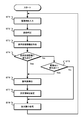
- FIG. 3 is a flowchart illustrating the operation of the image processing unit according to the first embodiment.
- the image processing unit inputs a captured image.
- the image processing unit 30-1 inputs the image signal of the captured image acquired by the imaging unit 20 and proceeds to step ST2.
- the image processing unit performs distortion correction in step ST2.
- the image processing unit 30-1 corrects the distortion aberration generated in the captured image by the imaging lens 21 of the imaging unit 20 and proceeds to step ST3.
- step ST3 the image processing unit acquires usage status information.
- the image processing unit 30-1 acquires the usage status information generated by the usage status information generation unit 40 and proceeds to step ST4.
- step ST4 the image processing unit determines whether the usage status information has changed.
- the image processing unit 30-1 determines that the usage status information has changed and proceeds to step ST6. If they match, it is determined that there is no change and the process proceeds to step ST5.
- step ST5 the image processing unit determines whether or not the captured image has changed.
- the image processing unit 30-1 determines that the imaged image has changed, proceeds to step ST6, and matches. In this case, it is determined that there is no change, and the process proceeds to step ST8.
- step ST6 the image processing unit detects the subject.
- the image processing unit 30-1 detects a subject using the captured image input in step ST1 and proceeds to step ST7.
- the image processing unit sets a region of interest in step ST7.
- the image processing unit 30-1 sets the attention area in the captured image based on the use state information acquired in step ST3 and the subject detection result obtained in step ST6. For example, when the imaging unit 20 is fixed to the moving body with the moving direction of the moving body as the imaging direction as described above, the image processing unit 30-1 includes a subject located in the moving direction of the moving body. A rectangular area is set as the attention area.
- the image processing unit 30-1 sets a region of interest and proceeds to step ST8.
- step ST8 the image processing unit performs enlargement / reduction processing.
- the image processing unit 30-1 enlarges the attention area set in step ST7 at a predetermined enlargement ratio. Further, since the image size of the captured image increases when the attention area is enlarged, the non-attention area is reduced so that the information acquired by the imaging unit is included in the image after the conversion process.
- the image processing unit 30-1 performs the enlargement / reduction processing in the horizontal direction based on the equation (1), and the enlargement / reduction processing in the vertical direction based on the equation (2), for example.
- the horizontal expansion rate of the attention area is “Kht> 1”
- the horizontal expansion rate of the non-attention area is “Khe ⁇ 1”
- the vertical expansion rate of the attention area is “Kvt> 1.”
- the enlargement ratio of the area in the vertical direction is “Kve ⁇ 1”.
- Total number of pixels in the horizontal direction number of pixels in the horizontal direction of the region of interest x Kht + Number of horizontal pixels in non-target area x Khe (1)
- Total number of pixels in the vertical direction number of pixels in the vertical direction of the region of interest x Kvt + Number of vertical pixels in non-target area x Kve (2)
- the image processing unit 30-1 outputs the image signal of the display image in which the attention area is enlarged and the non-attention area is reduced to the display unit 50 and returns to step ST1.
- FIG. 4 shows an operation example of the image processing unit.
- FIG. 4A illustrates an imaged image after distortion aberration correction.
- the subject (subject) OBa located in the moving direction has a smaller display size than other subjects OBb, and is less noticeable.
- the rectangular area including the object OBa located in the moving direction of the moving body is set as the attention area AT to perform the enlargement processing of the attention area, and the object OBa is enlarged and displayed as shown in FIG. 4B. Then, it becomes possible to call the user's attention to the subject OBa.
- the image processing unit 30-1 performs enlargement processing of the attention area and reduction processing of other non-attention areas so that the information acquired by the imaging unit is included in the image after the conversion processing.
- the subject OBa is enlarged and displayed, and the user's attention can be called to the subject OBa. Further, it is possible to recognize the subject OBb in the non-attention area.
- a captured image can be presented so that the user's attention can be drawn to a subject of interest without damaging the information acquired by the image capturing unit 20.
- FIG. 5 shows the configuration of the second embodiment of the image processing unit.
- the image processing unit 30-2 includes a subject detection unit 32, an input unit 33, a attention area setting unit 34, a conversion processing unit 36, and an output unit 37.
- the subject detection unit 32 performs recognition processing using the image signal after distortion correction supplied from the distortion correction unit 31 and detects a subject located within the imaging range.
- the subject detection unit 32 outputs the detection result of the subject to the attention area setting unit 34.
- the input unit 33 acquires the usage status information from the usage status information generation unit 40 and outputs it to the attention area setting unit 34.
- the attention area setting unit 34 determines the captured image based on the usage state information indicating the usage state of the imaging unit 20 that has acquired the captured image and the subject detection result of the subject detection unit 32. Set the area of interest.
- the attention area setting unit 34 outputs attention area information indicating the set attention area to the conversion processing unit 36.
- the conversion processing unit 36 uses the image signal of the captured image obtained by the imaging unit 20 to perform distortion aberration correction processing, attention area enlargement processing, and non-attention area reduction processing.
- the conversion processing unit 36 corrects the distortion aberration occurring in the captured image based on the optical characteristic information of the imaging lens 21 used in the imaging unit 20. Further, the conversion processing unit 36 enlarges the image of the attention area set by the attention area setting unit 34. Further, the conversion processing unit 36 reduces the non-focused region so that the information obtained by the imaging unit 20 is included in the image after the conversion process because the image size increases by enlarging the focused region.
- the conversion processing unit 36 uses the image signal of the captured image acquired by the image capturing unit 20 to perform coordinate conversion for generating an image signal in which the distortion aberration is corrected and the image is scaled up and down, and after the conversion process is performed.
- the image signal is output to the output unit 37.
- the output unit 37 performs resolution conversion that converts the image signal that has been subjected to distortion correction and scaling to an image signal of the display resolution of the display unit 50, and the image signal after the resolution conversion is in a format that can be input to the display unit 50. Output as a signal.
- FIG. 6 is a flowchart showing the operation of the second embodiment of the image processing unit.
- the image processing unit inputs a captured image.
- the image processing unit 30-2 inputs the image signal of the captured image acquired by the imaging unit 20 and proceeds to step ST12.
- step ST12 the image processing unit acquires usage status information.
- the image processing unit 30-2 acquires the usage status information generated by the usage status information generation unit 40 and proceeds to step ST13.
- step ST13 the image processing unit determines whether the usage status information has changed. If the usage status information acquired in step ST12 is different from the usage status information acquired in the previous processing in step ST12, the image processing unit 30-2 determines that the usage status information has changed and proceeds to step ST15. If they match, it is determined that there is no change and the process proceeds to step ST14.
- step ST14 the image processing unit determines whether the captured image has changed.
- the image processing unit 30-2 determines that the imaged image has changed, proceeds to step ST15, and matches. In this case, it is determined that there is no change, and the process proceeds to step ST17.
- step ST15 the image processing unit detects the subject.
- the image processing unit 30-2 performs subject detection using the captured image input in step ST1 and proceeds to step ST16.
- the image processing unit sets a region of interest in step ST16.
- the image processing unit 30-2 sets the attention area in the captured image based on the use state information acquired in step ST12 and the subject detection result obtained in step ST15. For example, when the imaging unit 20 is fixed to the moving body with the moving direction of the moving body as the imaging direction as described above, the image processing unit 30-2 includes a subject located in the moving direction of the moving body. A rectangular area is set as the attention area.
- the image processing unit 30-2 sets a region of interest and proceeds to step ST17.
- the image processing unit performs conversion processing in step ST17.
- the image processing unit 30-2 performs, as conversion processes, a process of correcting the distortion aberration generated in the captured image by the imaging lens 21 of the image capturing unit 20 and a process of enlarging the attention area set in step ST16 at a predetermined enlargement ratio. Then, the reduction processing of the non-attention area is performed according to the enlargement of the attention area.
- the image processing unit 30-2 outputs the image signal of the display image in which the distortion is corrected, the attention area is enlarged and the non-attention area is reduced, to the display unit 50, and the process returns to step ST11.
- the captured image so that the user's attention can be drawn to the subject of interest without damaging the information acquired by the image capturing unit 20.
- the attention area can be enlarged, and the non-attention area can be reduced by the conversion processing, the display image can be generated more efficiently than in the first embodiment.
- the subject detection unit 32 detects the type of subject by performing the recognition process using the captured images, but detects the movement of the subject using the plurality of captured images in time order. May be.
- the attention area setting unit 34 may use the movement of the subject to set the attention area. For example, an area where the moving direction of the moving object and the moving direction of the subject intersect each other is set as a high-risk area, and an image area of the subject that moves so as to be located in the high-risk area is set as the attention area.
- the movement of the subject may be detected based on the optical flow calculated using the imaged image acquired by the image capturing unit 20. In this way, if the attention area is set in consideration of the movement of the subject, it is possible to present a captured image that can call the user's attention to the subject that has caused a movement such as collision or contact with a moving body.
- the conversion processing unit 35 may adjust the enlargement ratio of the attention area according to the usage state information or according to the risk degree of the attention area.
- the conversion processing unit 35 adjusts the enlargement ratio of the attention area according to, for example, the moving speed of the moving body indicated by the use state information, and increases the enlargement ratio as the moving speed increases. By adjusting the enlargement ratio in this way, when the moving speed is high, the subject to be noted is displayed in a large size even if it is far, so that the user can be alerted to the subject to be noted.
- the conversion processing unit 35 adjusts the enlargement ratio of the attention area according to the risk degree of the attention area, and increases the enlargement ratio as the danger degree increases.
- the user can determine that the risk is high depending on the display size of the subject, and when the risk is high and the subject is displayed large, for example, the moving body is quickly stopped. It becomes possible to appropriately perform the risk avoidance operation such as.
- the attention area is a high risk area. It is not limited to the image area of the subject located at.
- the speed of the vehicle equipped with the imaging unit is used as the usage state information, and the object recognition result and the motion detection result are used as the object detection result.
- the attention area setting unit sets, as the attention area, an image area of another vehicle approaching the vehicle equipped with the imaging unit at a speed higher than a predetermined speed, for example. Further, the enlargement ratio may be increased as the approaching speed becomes higher.
- the technology according to the present disclosure can be applied to various products.
- the technology according to the present disclosure is applicable to any type of movement such as an automobile, an electric vehicle, a hybrid electric vehicle, a motorcycle, a bicycle, a personal mobility, an airplane, a drone, a ship, a robot, a construction machine, and an agricultural machine (tractor). It may be realized as a device mounted on the body.
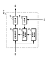
- FIG. 7 is a block diagram showing a schematic configuration example of a vehicle control system 7000 which is an example of a mobile body control system to which the technology according to the present disclosure can be applied.
- the vehicle control system 7000 includes a plurality of electronic control units connected via a communication network 7010.
- the vehicle control system 7000 includes a drive system control unit 7100, a body system control unit 7200, a battery control unit 7300, a vehicle exterior information detection unit 7400, a vehicle interior information detection unit 7500, and an integrated control unit 7600. .
- the communication network 7010 connecting these plural control units complies with any standard such as CAN (Controller Area Network), LIN (Local Interconnect Network), LAN (Local Area Network) or FlexRay (registered trademark). It may be an in-vehicle communication network.
- CAN Controller Area Network
- LIN Local Interconnect Network
- LAN Local Area Network
- FlexRay registered trademark
- Each control unit includes a microcomputer that performs arithmetic processing according to various programs, a storage unit that stores a program executed by the microcomputer or parameters used for various arithmetic operations, and a drive circuit that drives various controlled devices. Equipped with.
- Each control unit is equipped with a network I / F for communicating with other control units via the communication network 7010, and is also used for wired or wireless communication with devices or sensors inside or outside the vehicle. A communication I / F for performing communication is provided. In FIG.
- a microcomputer 7610 a general-purpose communication I / F 7620, a dedicated communication I / F 7630, a positioning unit 7640, a beacon receiving unit 7650, an in-vehicle device I / F 7660, an audio image output unit 7670, An in-vehicle network I / F 7680 and a storage unit 7690 are illustrated.
- the other control units also include a microcomputer, a communication I / F, a storage unit, and the like.
- the drive system control unit 7100 controls the operation of devices related to the drive system of the vehicle according to various programs.
- the drive system control unit 7100 includes a drive force generation device for generating a drive force of a vehicle such as an internal combustion engine or a drive motor, a drive force transmission mechanism for transmitting the drive force to wheels, and a steering angle of the vehicle. It functions as a steering mechanism for adjusting and a control device such as a braking device for generating a braking force of the vehicle.
- the drive system control unit 7100 may have a function as a control device such as ABS (Antilock Brake System) or ESC (Electronic Stability Control).
- a vehicle state detection unit 7110 is connected to the drive system control unit 7100.
- the vehicle state detection unit 7110 includes, for example, a gyro sensor that detects the angular velocity of the shaft rotational movement of the vehicle body, an acceleration sensor that detects the acceleration of the vehicle, or an accelerator pedal operation amount, a brake pedal operation amount, or a steering wheel steering operation. At least one of the sensors for detecting the angle, the engine speed, the wheel rotation speed, etc. is included.
- the drive system control unit 7100 performs arithmetic processing using the signal input from the vehicle state detection unit 7110 to control the internal combustion engine, drive motor, electric power steering device, brake device, or the like.
- the body system control unit 7200 controls the operation of various devices mounted on the vehicle body according to various programs.
- the body system control unit 7200 functions as a keyless entry system, a smart key system, a power window device, or a control device for various lamps such as a head lamp, a back lamp, a brake lamp, a winker, or a fog lamp.
- the body system control unit 7200 may receive radio waves or signals of various switches transmitted from a portable device that substitutes for a key.
- the body system control unit 7200 receives the input of these radio waves or signals and controls the vehicle door lock device, the power window device, the lamp, and the like.
- the battery control unit 7300 controls the secondary battery 7310 that is the power supply source of the drive motor according to various programs. For example, to the battery control unit 7300, information such as the battery temperature, the battery output voltage, or the remaining capacity of the battery is input from the battery device including the secondary battery 7310. The battery control unit 7300 performs arithmetic processing using these signals to control the temperature adjustment of the secondary battery 7310 or the cooling device or the like provided in the battery device.
- the exterior information detection unit 7400 detects information outside the vehicle equipped with the vehicle control system 7000.
- the image capturing unit 7410 and the vehicle exterior information detection unit 7420 is connected to the vehicle exterior information detection unit 7400.
- the imaging unit 7410 includes at least one of a ToF (Time Of Flight) camera, a stereo camera, a monocular camera, an infrared camera, and other cameras.
- the outside-vehicle information detection unit 7420 detects, for example, an environment sensor for detecting current weather or weather, or another vehicle around the vehicle equipped with the vehicle control system 7000, an obstacle, a pedestrian, or the like. At least one of the ambient information detection sensors of.
- the environment sensor may be, for example, at least one of a raindrop sensor that detects rainy weather, a fog sensor that detects fog, a sunshine sensor that detects the degree of sunshine, and a snow sensor that detects snowfall.
- the ambient information detection sensor may be at least one of an ultrasonic sensor, a radar device, and a LIDAR (Light Detection and Ranging, Laser Imaging Detection and Ranging) device.
- the imaging unit 7410 and the vehicle exterior information detection unit 7420 may be provided as independent sensors or devices, or may be provided as a device in which a plurality of sensors or devices are integrated.
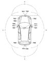
- FIG. 8 shows an example of installation positions of the image pickup unit 7410 and the vehicle exterior information detection unit 7420.
- the imaging units 7910, 7912, 7914, 7916, 7918 are provided at at least one of the front nose of the vehicle 7900, the side mirrors, the rear bumper, the back door, and the upper part of the windshield inside the vehicle.
- the image capturing unit 7910 provided on the front nose and the image capturing unit 7918 provided on the upper part of the windshield in the vehicle interior mainly acquire an image in front of the vehicle 7900.
- the imaging units 7912 and 7914 provided in the side mirrors mainly acquire images of the side of the vehicle 7900.
- the imaging unit 7916 provided in the rear bumper or the back door mainly acquires an image of the rear of the vehicle 7900.
- the imaging unit 7918 provided on the upper part of the windshield in the vehicle interior is mainly used for detecting a preceding vehicle, a pedestrian, an obstacle, a traffic signal, a traffic sign, a lane, or the like.
- FIG. 8 shows an example of the shooting ranges of the respective image pickup units 7910, 7912, 7914, 7916.
- the imaging range a indicates the imaging range of the imaging unit 7910 provided on the front nose
- the imaging ranges b and c indicate the imaging ranges of the imaging units 7912 and 7914 provided on the side mirrors
- the imaging range d is The imaging range of the imaging part 7916 provided in the rear bumper or the back door is shown. For example, by overlaying the image data captured by the image capturing units 7910, 7912, 7914, and 7916, a bird's-eye view image of the vehicle 7900 viewed from above can be obtained.
- the vehicle exterior information detection units 7920, 7922, 7924, 7926, 7928, 7930 provided on the front, rear, sides, corners of the vehicle 7900 and on the upper part of the windshield inside the vehicle may be ultrasonic sensors or radar devices, for example.
- the vehicle exterior information detection units 7920, 7926, 7930 provided on the front nose, rear bumper, back door, and upper windshield of the vehicle 7900 may be, for example, LIDAR devices.
- These vehicle exterior information detection units 7920 to 7930 are mainly used for detecting a preceding vehicle, a pedestrian, an obstacle, or the like.
- the vehicle exterior information detection unit 7400 causes the image capturing unit 7410 to capture an image of the vehicle exterior and receives the captured image data. Further, the vehicle exterior information detection unit 7400 receives detection information from the vehicle exterior information detection unit 7420 connected thereto. When the vehicle exterior information detection unit 7420 is an ultrasonic sensor, a radar device, or a LIDAR device, the vehicle exterior information detection unit 7400 transmits ultrasonic waves, electromagnetic waves, or the like, and receives information on the received reflected waves.
- the vehicle exterior information detection unit 7400 may perform object detection processing or distance detection processing such as people, vehicles, obstacles, signs, or characters on the road surface based on the received information.
- the vehicle exterior information detection unit 7400 may perform environment recognition processing for recognizing rainfall, fog, road surface conditions, or the like based on the received information.
- the vehicle exterior information detection unit 7400 may calculate the distance to an object outside the vehicle based on the received information.
- the vehicle exterior information detection unit 7400 may also perform image recognition processing or distance detection processing for recognizing people, vehicles, obstacles, signs, characters on the road surface, or the like based on the received image data.
- the vehicle exterior information detection unit 7400 performs processing such as distortion correction or position adjustment on the received image data, combines the image data captured by different image capturing units 7410, and generates an overhead image or a panoramic image. Good.
- the vehicle exterior information detection unit 7400 may perform viewpoint conversion processing using image data captured by different image capturing units 7410.
- the in-vehicle information detection unit 7500 detects in-vehicle information.
- a driver state detection unit 7510 that detects the state of the driver is connected.
- the driver state detection unit 7510 may include a camera that captures an image of the driver, a biometric sensor that detects biometric information of the driver, a microphone that collects voice in the vehicle interior, and the like.
- the biometric sensor is provided on, for example, a seat surface or a steering wheel, and detects biometric information of an occupant sitting on a seat or a driver who holds the steering wheel.
- the in-vehicle information detection unit 7500 may calculate the degree of tiredness or concentration of the driver based on the detection information input from the driver state detection unit 7510, and determines whether the driver is asleep. You may.
- the in-vehicle information detection unit 7500 may perform processing such as noise canceling processing on the collected audio signal.
- the integrated control unit 7600 controls overall operations in the vehicle control system 7000 according to various programs.
- An input unit 7800 is connected to the integrated control unit 7600.
- the input unit 7800 is realized by, for example, a device such as a touch panel, a button, a microphone, a switch or a lever that can be input and operated by a passenger. Data obtained by voice recognition of voice input by a microphone may be input to the integrated control unit 7600.
- the input unit 7800 may be, for example, a remote control device that uses infrared rays or other radio waves, or may be an external connection device such as a mobile phone or a PDA (Personal Digital Assistant) that supports the operation of the vehicle control system 7000. May be.
- the input unit 7800 may be, for example, a camera, in which case the passenger can input information by gesture. Alternatively, data obtained by detecting the movement of the wearable device worn by the passenger may be input. Furthermore, the input unit 7800 may include, for example, an input control circuit that generates an input signal based on information input by a passenger or the like using the input unit 7800 and outputs the input signal to the integrated control unit 7600. A passenger or the like operates the input unit 7800 to input various data or instruct a processing operation to the vehicle control system 7000.
- the storage unit 7690 may include a ROM (Read Only Memory) that stores various programs executed by the microcomputer, and a RAM (Random Access Memory) that stores various parameters, calculation results, sensor values, and the like.
- the storage unit 7690 may be realized by a magnetic storage device such as an HDD (Hard Disc Drive), a semiconductor storage device, an optical storage device, a magneto-optical storage device, or the like.
- the general-purpose communication I / F 7620 is a general-purpose communication I / F that mediates communication with various devices existing in the external environment 7750.
- the general-purpose communication I / F 7620 is a cellular communication protocol such as GSM (registered trademark) (Global System of Mobile communications), WiMAX (registered trademark), LTE (registered trademark) (Long Term Evolution), or LTE-A (LTE-Advanced).
- GSM Global System of Mobile communications
- WiMAX registered trademark
- LTE registered trademark
- LTE-A Long Term Evolution
- LTE-A Long Term Evolution-Advanced
- another wireless communication protocol such as a wireless LAN (also referred to as Wi-Fi (registered trademark)) or Bluetooth (registered trademark) may be implemented.
- the general-purpose communication I / F 7620 is connected to a device (for example, an application server or a control server) existing on an external network (for example, the Internet, a cloud network, or a network unique to an operator) via a base station or an access point, for example. You may. Further, the general-purpose communication I / F 7620 is, for example, using P2P (Peer To Peer) technology, a terminal existing in the vicinity of the vehicle (for example, a driver, a pedestrian or a shop terminal, or an MTC (Machine Type Communication) terminal). May be connected with.
- P2P Peer To Peer
- a terminal existing in the vicinity of the vehicle for example, a driver, a pedestrian or a shop terminal, or an MTC (Machine Type Communication) terminal. May be connected with.
- the dedicated communication I / F 7630 is a communication I / F that supports a communication protocol formulated for use in a vehicle.
- the dedicated communication I / F 7630 uses a standard protocol such as WAVE (Wireless Access in Vehicle Environment), DSRC (Dedicated Short Range Communications), or a cellular communication protocol, which is a combination of a lower layer IEEE 802.11p and an upper layer IEEE 1609, for example. May be implemented.
- the dedicated communication I / F 7630 is typically a vehicle-to-vehicle communication, a vehicle-to-infrastructure communication, a vehicle-to-home communication and a vehicle-to-pedestrian communication. ) Perform V2X communications, a concept that includes one or more of the communications.
- the positioning unit 7640 receives, for example, a GNSS signal from a GNSS (Global Navigation Satellite System) satellite (for example, a GPS signal from a GPS (Global Positioning System) satellite) to perform positioning, and the latitude, longitude, and altitude of the vehicle. Generate position information including. Note that the positioning unit 7640 may specify the current position by exchanging signals with the wireless access point, or may acquire position information from a terminal such as a mobile phone, PHS, or smartphone having a positioning function.
- GNSS Global Navigation Satellite System
- GPS Global Positioning System
- the beacon receiving unit 7650 receives, for example, a radio wave or an electromagnetic wave transmitted from a wireless station or the like installed on the road, and acquires information such as the current position, traffic jam, traffic closure, or required time.
- the function of beacon reception unit 7650 may be included in dedicated communication I / F 7630 described above.
- the in-vehicle device I / F 7660 is a communication interface that mediates a connection between the microcomputer 7610 and various in-vehicle devices 7760 existing in the vehicle.
- the in-vehicle device I / F 7660 may establish a wireless connection using a wireless communication protocol such as a wireless LAN, Bluetooth (registered trademark), NFC (Near Field Communication) or WUSB (Wireless USB).
- a wireless communication protocol such as a wireless LAN, Bluetooth (registered trademark), NFC (Near Field Communication) or WUSB (Wireless USB).
- the in-vehicle device I / F 7660 can be connected to a USB (Universal Serial Bus), HDMI (registered trademark) (High-Definition Multimedia Interface, or MHL (Mobile High) via a connection terminal (and a cable if necessary) not shown. -Definition Link) etc.
- the in-vehicle device 7760 includes, for example, at least one of a mobile device or a wearable device that the passenger has, or an information device that is carried in or attached to the vehicle.
- the in-vehicle device 7760 may include a navigation device that searches for a route to an arbitrary destination.
- the in-vehicle device I / F 7660 is a control signal between the in-vehicle device 7760 and the in-vehicle device 7760. Or exchange data signals.
- the in-vehicle network I / F 7680 is an interface that mediates communication between the microcomputer 7610 and the communication network 7010.
- the vehicle-mounted network I / F 7680 transmits and receives signals and the like according to a predetermined protocol supported by the communication network 7010.
- the microcomputer 7610 of the integrated control unit 7600 passes through at least one of the general-purpose communication I / F 7620, the dedicated communication I / F 7630, the positioning unit 7640, the beacon receiving unit 7650, the in-vehicle device I / F 7660, and the in-vehicle network I / F 7680.
- the vehicle control system 7000 is controlled according to various programs based on the information acquired by the above. For example, the microcomputer 7610 calculates the control target value of the driving force generation device, the steering mechanism or the braking device based on the acquired information on the inside and outside of the vehicle, and outputs the control command to the drive system control unit 7100. Good.
- the microcomputer 7610 realizes the functions of ADAS (Advanced Driver Assistance System) including avoidance or impact mitigation of a vehicle, follow-up traveling based on an inter-vehicle distance, vehicle speed maintenance traveling, a vehicle collision warning, or a vehicle lane departure warning. You may perform the cooperative control aiming at.
- the microcomputer 7610 controls the driving force generation device, the steering mechanism, the braking device, and the like based on the acquired information about the surroundings of the vehicle, so that the microcomputer 7610 automatically travels independently of the driver's operation. You may perform the cooperative control for the purpose of driving etc.
- ADAS Advanced Driver Assistance System
- a general-purpose communication I / F 7620 a dedicated communication I / F 7630, a positioning unit 7640, a beacon receiving unit 7650, an in-vehicle device I / F 7660, and an in-vehicle network I / F 7680.
- the microcomputer 7610 may predict a danger such as a vehicle collision, a proximity of a pedestrian or the like, or an approach to a closed road by a vehicle based on the acquired information, and may generate a warning signal.
- the warning signal may be, for example, a signal for generating a warning sound or turning on a warning lamp.
- the voice image output unit 7670 transmits an output signal of at least one of a voice and an image to an output device capable of visually or audibly notifying information to a passenger of the vehicle or the outside of the vehicle.
- an audio speaker 7710, a display unit 7720, and an instrument panel 7730 are illustrated as output devices.
- the display unit 7720 may include at least one of an onboard display and a head-up display, for example.
- the display unit 7720 may have an AR (Augmented Reality) display function.
- the output device may be a device other than these devices, such as headphones, a wearable device such as a glasses-type display worn by a passenger, a projector, or a lamp.
- the display device displays results obtained by various processes performed by the microcomputer 7610 or information received from another control unit in various formats such as text, images, tables, and graphs. Display visually.
- the audio output device converts an audio signal composed of reproduced audio data, acoustic data, or the like into an analog signal and outputs it audibly.
- control units connected via the communication network 7010 may be integrated as one control unit.
- each control unit may be composed of a plurality of control units.
- the vehicle control system 7000 may include another control unit not shown.
- some or all of the functions of one of the control units may be given to another control unit. That is, as long as information is transmitted and received via the communication network 7010, the predetermined arithmetic processing may be performed by any control unit.
- a sensor or device connected to one of the control units may be connected to another control unit, and a plurality of control units may send and receive detection information to and from each other via the communication network 7010. .
- the computer program for realizing each function of the information processing apparatus according to the present embodiment described with reference to FIG. 7 can be installed in any control unit or the like. It is also possible to provide a computer-readable recording medium in which such a computer program is stored.
- the recording medium is, for example, a magnetic disk, an optical disk, a magneto-optical disk, a flash memory, or the like. Further, the above computer program may be distributed, for example, via a network without using a recording medium.
- the image processing unit 30 can be applied to the integrated control unit 7600 shown in FIG. 7. Further, the image pickup unit 7916 of FIG. 8 is used as the image pickup unit 20, the vehicle state detection unit 7110 of FIG. 7 is used as the usage state information generation unit 40, and the display unit 7720 of FIG. 7 is used as the display unit 50.
- the usage state information generation unit 40 when applied to the vehicle control system, the usage state information generation unit 40 generates the information indicating the vehicle speed and the steering angle as the usage state information. Further, the image processing unit 30 may use the use state information to calculate, for example, a risk point indicating a risk level, and set the attention area based on the calculated risk point.
- the attention area setting unit 34 divides the rear of the vehicle CR equipped with the vehicle control system into a plurality of areas, for example, and calculates a risk point for each area. The area is divided based on the distance from the imaging unit and the direction with respect to the imaging unit.
- FIG. 9 shows an example of area division, and shows a case where the area behind the vehicle CR is divided into areas BA0 to BA9 based on the distance and direction.
- FIG. 10 is a diagram for explaining calculation of risk points.
- the risk point PT is, for example, the multiplication result of the vehicle speed point Pa, the distance point Pb, the guideline point Pc, and the civilization point Pd.
- the vehicle speed point Pa is a point corresponding to the vehicle speed, and the point value increases as the vehicle speed increases.
- FIG. 11 is a diagram for explaining the distance point Pb and the guideline point Pc.
- the distance point Pb is a point corresponding to the distance LA to the area.
- the image processing unit 30 increases the point value as the distance LA to the area becomes shorter.
- the guideline point Pc is a point according to whether or not the area is included in the vehicle passing scheduled area AMF when the vehicle CR moves in the moving direction MF determined based on the steering angle.
- the image processing unit 30 increases the point value when the area is within the vehicle passage scheduled area AMF.
- the personality point Pd is a point corresponding to the detected civilization of the subject.
- the image processing unit 30 increases the point value when it is determined that the detected subject is a person, and decreases the point value when it is determined that the detected subject is not a person.
- the reference for giving the giving points and the vehicle speed points Pa is an example, and is not limited to the case shown in FIG. 10.
- FIG. 12 shows an example of calculating risk points.
- the risk point PT (BA5) in the area BA5 has a value shown in Expression (3).
- the vehicle speed point Pa is "2”
- the distance point Pb of the area BA5 is "3”
- the guideline point Pc is "5"
- the humanity point Pd is "0.9”
- the risk point is " 27 ".
- the risk point PT (BA9) in the area BA9 has a value shown in Expression (4). If the vehicle speed point Pa is “2”, the distance point Pb of the area BA9 is “2”, the guideline point Pc is “1”, and the civilization point Pd is “0.8”, the risk point is “3”. .2 ”.
- the risk points PT (BA0) to PT (BA4) and PT (BA6) to PT (BA9) are calculated in the same manner. Note that, in FIG. 12, subjects in other areas are omitted, and the numbers indicated by “” in each area indicate risk points.
- the image processing unit 30 sets the area having the highest risk point as the attention area based on the risk points calculated for each area. For example, when the risk points are calculated as shown in FIG. 12, the area of the object OBc in the area BA5 (for example, the rectangular area including the object OBc) is set as the attention area.
- FIG. 13 is a diagram for explaining the enlargement / reduction processing.
- FIG. 13A illustrates a change in the enlargement ratio.
- the enlargement ratio increases as the width increases, and the width increases. It shows that the expansion ratio is smaller as is smaller.
- the arrows inside the displays RSh and RSv indicate the enlargement / reduction direction.
- the image processing unit 30 enlarges the subject OBc by making the enlargement ratio of the attention area larger than “1”.
- the image processing unit 30 sets the enlargement ratio of the non-attention region to be lower than “1” and decreases as the distance from the attention region increases, and the information of the non-attention region is lost even if the attention region is enlarged.
- the display unit 7720 as shown in (b) of FIG. 13, an image in which the object OBc in the attention area having a high risk point is enlarged and the object OBd in the non-attention area having a low risk point is reduced is displayed. Is displayed.
- the change of the enlargement ratio is not limited to the case where the enlargement ratio is linearly increased or decreased as shown in FIG.
- the enlargement ratio may be changed non-linearly.
- the change of the enlargement ratio may be increased on the end side of the captured image, and the subject on the end side may be further reduced as compared with the case where the enlargement ratio is changed linearly.
- the image processing unit 30 can display a captured image so as to call the user's attention to the subject OBc in the attention area. Further, since the subject OBd in the non-attention area is reduced and displayed, it can be grasped that the subject OBd exists behind.
- the image processing unit 30 raises the risk point of the area intersecting with the subject having the movement toward the planned vehicle passage area AMF. By increasing the risk point of the intersecting area in this manner, it becomes possible to magnify and display the person walking toward the vehicle passage scheduled area AMF, and it is possible to effectively perform the magnified display.
- the movement of the subject may be detected using the detection result of the vehicle exterior information detection unit 7930 shown in FIG. 8 or may be detected using the optical flow calculated from the image captured by the image capturing unit 7916. .
- the image processing unit 30 may adjust the enlargement ratio of the attention area according to the degree of risk.
- the image processing unit 30 increases the enlargement ratio of the attention area as the risk level increases, and further draws the user's attention to the subject having a high risk level. Make it easier.
- the attention region is not limited to the subject located in the region having the highest risk point.
- a subject located in one or a plurality of areas whose risk points exceed a preset threshold may be set as the attention area.
- the image pickup unit 20 and the image processing unit 30 are provided in the vehicle control system 7000 so that the attention area is set and the attention area is enlarged and the other non-attention area is reduced based on the risk point. This makes it possible to call the driver's attention in a timely manner. Further, even if the attention area is expanded to call attention, the other areas are displayed in a reduced size, so that the peripheral information acquired by the image capturing unit 20 can be presented to the driver without being lost.
- the series of processes described in the specification can be executed by hardware, software, or a composite configuration of both.
- a program recording a processing sequence is installed in a memory in a computer incorporated in dedicated hardware and executed.
- the program can be installed and executed in a general-purpose computer that can execute various processes.
- the program can be recorded in advance in a hard disk, SSD (Solid State Drive), or ROM (Read Only Memory) as a recording medium.
- the program is a flexible disk, CD-ROM (Compact Disc Read Only Memory), MO (Magneto optical) disc, DVD (Digital Versatile Disc), BD (Blu-Ray Disc (registered trademark)), magnetic disc, semiconductor memory card. It can be temporarily (or permanently) stored (recorded) in a removable recording medium such as.
- a removable recording medium can be provided as so-called package software.
- the program may be wirelessly or wired transferred from the download site to the computer via a network such as a LAN (Local Area Network) or the Internet.
- a network such as a LAN (Local Area Network) or the Internet.
- the program thus transferred can be received and installed in a recording medium such as a built-in hard disk.
- the image processing device of the present technology can also have the following configurations.
- An object detection unit that detects an object using an imaged image
- An attention area setting unit that sets an attention area for the captured image based on usage state information indicating a usage state of the imaging unit that has acquired the captured image and a subject detection result of the subject detection unit
- An image processing apparatus comprising: a conversion processing unit that expands the attention area and reduces other non-attention areas.
- the attention area setting unit determines a high-risk area in the captured image based on the usage state information, and sets an image area of a subject located in the high-risk area as the attention area.
- the usage state information is information regarding a change in relative positional relationship between a moving body provided with the imaging unit and a subject detected by the subject detection unit, The image processing device according to (2), wherein the attention area setting unit determines the high-risk area based on the change in the relative positional relationship.
- the use state information includes a moving speed and a moving direction of a moving body provided with the imaging unit, The image processing device according to (3), wherein the attention area setting unit determines the high-risk area based on a moving speed and a moving direction of the moving body.
- the moving body is a vehicle, and the captured image shows the rear of the vehicle
- the image processing apparatus according to (4), wherein the attention area setting unit determines the high-risk area based on the speed and the backward direction when the vehicle is moving backward.
- the image processing device according to (4) or (5), wherein the attention area setting unit determines the high-risk area by using the distance from the imaging unit.
- the image processing device according to any one of (4) to (6), wherein the attention area setting unit determines the high-risk area using the subject detection result of the subject detection unit.
- the image processing device according to any one of (3) to (7), in which the attention area setting unit divides the imaging range of the imaging unit into a plurality of areas and determines the degree of risk for each area.
- the image processing device (9) The image processing device according to (8), wherein the attention area setting unit divides the imaging range into a plurality of areas based on a distance from the imaging unit and a direction with respect to the imaging unit. (10) The conversion processing unit enlarges the attention area and reduces other non-attention areas so that the information acquired by the imaging unit is included in the image after the conversion processing (1) to (9).
- the attention area for the captured image is based on the usage state information indicating the usage state of the imaging unit that has acquired the captured image and the detection result of subject detection using the captured image. Is set, and the conversion processing for expanding the attention area and reducing other non-attention areas is performed. Therefore, by displaying the image after the conversion process, it becomes possible to call the user's attention to the subject to be noted without impairing the acquired information. Therefore, it is suitable for supporting a danger avoidance operation of a driver such as a vehicle.
- Imaging system 20 ... Imaging section 21 ... Imaging lens 22 ... Image sensor section 30, 30-1, 30-2 ... Image processing section 31 ... Distortion correction section 32 ... -Subject detection unit 33 ... input unit 34 ... attention area setting unit 35, 36 ... conversion processing unit 37 ... output unit 40 ... use state information generation unit 50 ... display unit
Landscapes
- Engineering & Computer Science (AREA)
- Computer Vision & Pattern Recognition (AREA)
- Physics & Mathematics (AREA)
- General Physics & Mathematics (AREA)
- Theoretical Computer Science (AREA)
- Traffic Control Systems (AREA)
- Image Processing (AREA)
Abstract
L'invention concerne une unité de détection de sujet 32 qui réalise une détection de sujet à l'aide d'une image capturée. Une région d'unité de définition de notification 34 définit une région de notification par rapport à l'image capturée sur la base d'informations d'état d'utilisation indiquant l'état d'utilisation d'une unité de capture d'image avec laquelle l'image capturée a été acquise et du résultat de la détection de sujet par l'unité de détection de sujet. La région de notification est une région d'image du sujet qui est située dans une région à haut risque à l'intérieur de l'image capturée. Une unité de traitement de conversion agrandit la région de notification et réduit d'autres régions de non-notification de telle sorte que des informations acquises avec l'unité de capture d'image sont incluses dans l'image ayant subi le processus de conversion. En affichant l'image convertie, l'attention de l'utilisateur peut être attirée vers le sujet dans une région souhaitée sans que les informations acquises avec l'unité de capture d'image soient détériorées.
Applications Claiming Priority (2)
| Application Number | Priority Date | Filing Date | Title |
|---|---|---|---|
| JP2018199046 | 2018-10-23 | ||
| JP2018-199046 | 2018-10-23 |
Publications (1)
| Publication Number | Publication Date |
|---|---|
| WO2020085101A1 true WO2020085101A1 (fr) | 2020-04-30 |
Family
ID=70330607
Family Applications (1)
| Application Number | Title | Priority Date | Filing Date |
|---|---|---|---|
| PCT/JP2019/039993 WO2020085101A1 (fr) | 2018-10-23 | 2019-10-10 | Dispositif de traitement d'image, procédé de traitement d'image et programme |
Country Status (1)
| Country | Link |
|---|---|
| WO (1) | WO2020085101A1 (fr) |
Cited By (2)
| Publication number | Priority date | Publication date | Assignee | Title |
|---|---|---|---|---|
| US11538226B2 (en) * | 2020-03-12 | 2022-12-27 | Honda Motor Co., Ltd. | Information processing device, information providing system, and information processing method |
| US11665391B2 (en) | 2021-01-13 | 2023-05-30 | Panasonic Intellectual Property Management Co., Ltd. | Signal processing device and signal processing system |
Citations (3)
| Publication number | Priority date | Publication date | Assignee | Title |
|---|---|---|---|---|
| JP2004038877A (ja) * | 2002-07-08 | 2004-02-05 | Yazaki Corp | 車両用周辺監視装置及び画像処理装置 |
| JP2007288586A (ja) * | 2006-04-18 | 2007-11-01 | Matsushita Electric Ind Co Ltd | 車両周囲状況確認装置 |
| JP2016110501A (ja) * | 2014-12-09 | 2016-06-20 | 株式会社デンソー | 画像生成装置 |
-
2019
- 2019-10-10 WO PCT/JP2019/039993 patent/WO2020085101A1/fr active Application Filing
Patent Citations (3)
| Publication number | Priority date | Publication date | Assignee | Title |
|---|---|---|---|---|
| JP2004038877A (ja) * | 2002-07-08 | 2004-02-05 | Yazaki Corp | 車両用周辺監視装置及び画像処理装置 |
| JP2007288586A (ja) * | 2006-04-18 | 2007-11-01 | Matsushita Electric Ind Co Ltd | 車両周囲状況確認装置 |
| JP2016110501A (ja) * | 2014-12-09 | 2016-06-20 | 株式会社デンソー | 画像生成装置 |
Cited By (2)
| Publication number | Priority date | Publication date | Assignee | Title |
|---|---|---|---|---|
| US11538226B2 (en) * | 2020-03-12 | 2022-12-27 | Honda Motor Co., Ltd. | Information processing device, information providing system, and information processing method |
| US11665391B2 (en) | 2021-01-13 | 2023-05-30 | Panasonic Intellectual Property Management Co., Ltd. | Signal processing device and signal processing system |
Similar Documents
| Publication | Publication Date | Title |
|---|---|---|
| US10957029B2 (en) | Image processing device and image processing method | |
| US11076141B2 (en) | Image processing device, image processing method, and vehicle | |
| JP2018029280A (ja) | 撮像装置と撮像方法 | |
| JPWO2018180579A1 (ja) | 撮像制御装置、および撮像制御装置の制御方法、並びに移動体 | |
| US20200349367A1 (en) | Image processing device, image processing method, and program | |
| US11443520B2 (en) | Image processing apparatus, image processing method, and image processing system | |
| JPWO2018180121A1 (ja) | 情報処理装置と情報処理方法 | |
| WO2020085101A1 (fr) | Dispositif de traitement d'image, procédé de traitement d'image et programme | |
| US11585898B2 (en) | Signal processing device, signal processing method, and program | |
| JP6981095B2 (ja) | サーバ装置、記録方法、プログラム、および記録システム | |
| US11689797B2 (en) | Camera, method, non-transitory computer-readable medium, and system | |
| WO2021256483A1 (fr) | Dispositif de commande, système de projection, procédé de commande, et programme | |
| WO2020195965A1 (fr) | Dispositif de traitement d'informations, procédé de traitement d'informations et programme | |
| WO2021125076A1 (fr) | Dispositif de traitement d'informations, procédé de traitement d'informations, programme, dispositif de capture d'image et système de capture d'image | |
| WO2019215979A1 (fr) | Dispositif de traitement d'image, dispositif embarqué, procédé de traitement d'image, et programme | |
| US20230412923A1 (en) | Signal processing device, imaging device, and signal processing method | |
| JP7173056B2 (ja) | 認識装置と認識方法およびプログラム | |
| WO2020195969A1 (fr) | Dispositif de traitement d'informations, procédé de traitement d'informations, et programme | |
| WO2020255589A1 (fr) | Dispositif de traitement d'informations, procédé de traitement d'informations et programme | |
| WO2019106995A1 (fr) | Dispositif et procédé de capture d'image, et programme |
Legal Events
| Date | Code | Title | Description |
|---|---|---|---|
| 121 | Ep: the epo has been informed by wipo that ep was designated in this application |
Ref document number: 19876520 Country of ref document: EP Kind code of ref document: A1 |
|
| NENP | Non-entry into the national phase |
Ref country code: DE |
|
| 122 | Ep: pct application non-entry in european phase |
Ref document number: 19876520 Country of ref document: EP Kind code of ref document: A1 |
|
| NENP | Non-entry into the national phase |
Ref country code: JP |