WO2020195969A1 - 情報処理装置、情報処理方法及びプログラム - Google Patents
情報処理装置、情報処理方法及びプログラム Download PDFInfo
- Publication number
- WO2020195969A1 WO2020195969A1 PCT/JP2020/011178 JP2020011178W WO2020195969A1 WO 2020195969 A1 WO2020195969 A1 WO 2020195969A1 JP 2020011178 W JP2020011178 W JP 2020011178W WO 2020195969 A1 WO2020195969 A1 WO 2020195969A1
- Authority
- WO
- WIPO (PCT)
- Prior art keywords
- information processing
- processing device
- captured image
- area
- unit
- Prior art date
Links
Images


Classifications
-
- G—PHYSICS
- G06—COMPUTING; CALCULATING OR COUNTING
- G06T—IMAGE DATA PROCESSING OR GENERATION, IN GENERAL
- G06T7/00—Image analysis
- G06T7/10—Segmentation; Edge detection
- G06T7/11—Region-based segmentation
-
- G—PHYSICS
- G06—COMPUTING; CALCULATING OR COUNTING
- G06T—IMAGE DATA PROCESSING OR GENERATION, IN GENERAL
- G06T7/00—Image analysis
-
- G—PHYSICS
- G06—COMPUTING; CALCULATING OR COUNTING
- G06T—IMAGE DATA PROCESSING OR GENERATION, IN GENERAL
- G06T7/00—Image analysis
- G06T7/10—Segmentation; Edge detection
- G06T7/174—Segmentation; Edge detection involving the use of two or more images
-
- G—PHYSICS
- G06—COMPUTING; CALCULATING OR COUNTING
- G06V—IMAGE OR VIDEO RECOGNITION OR UNDERSTANDING
- G06V10/00—Arrangements for image or video recognition or understanding
- G06V10/20—Image preprocessing
- G06V10/25—Determination of region of interest [ROI] or a volume of interest [VOI]
-
- G—PHYSICS
- G06—COMPUTING; CALCULATING OR COUNTING
- G06V—IMAGE OR VIDEO RECOGNITION OR UNDERSTANDING
- G06V10/00—Arrangements for image or video recognition or understanding
- G06V10/70—Arrangements for image or video recognition or understanding using pattern recognition or machine learning
- G06V10/74—Image or video pattern matching; Proximity measures in feature spaces
- G06V10/75—Organisation of the matching processes, e.g. simultaneous or sequential comparisons of image or video features; Coarse-fine approaches, e.g. multi-scale approaches; using context analysis; Selection of dictionaries
- G06V10/751—Comparing pixel values or logical combinations thereof, or feature values having positional relevance, e.g. template matching
-
- G—PHYSICS
- G06—COMPUTING; CALCULATING OR COUNTING
- G06V—IMAGE OR VIDEO RECOGNITION OR UNDERSTANDING
- G06V10/00—Arrangements for image or video recognition or understanding
- G06V10/70—Arrangements for image or video recognition or understanding using pattern recognition or machine learning
- G06V10/74—Image or video pattern matching; Proximity measures in feature spaces
- G06V10/761—Proximity, similarity or dissimilarity measures
-
- G—PHYSICS
- G06—COMPUTING; CALCULATING OR COUNTING
- G06T—IMAGE DATA PROCESSING OR GENERATION, IN GENERAL
- G06T2207/00—Indexing scheme for image analysis or image enhancement
- G06T2207/10—Image acquisition modality
- G06T2207/10016—Video; Image sequence
-
- G—PHYSICS
- G06—COMPUTING; CALCULATING OR COUNTING
- G06T—IMAGE DATA PROCESSING OR GENERATION, IN GENERAL
- G06T2207/00—Indexing scheme for image analysis or image enhancement
- G06T2207/30—Subject of image; Context of image processing
- G06T2207/30232—Surveillance
-
- G—PHYSICS
- G06—COMPUTING; CALCULATING OR COUNTING
- G06T—IMAGE DATA PROCESSING OR GENERATION, IN GENERAL
- G06T2207/00—Indexing scheme for image analysis or image enhancement
- G06T2207/30—Subject of image; Context of image processing
- G06T2207/30248—Vehicle exterior or interior
- G06T2207/30252—Vehicle exterior; Vicinity of vehicle
- G06T2207/30261—Obstacle
Definitions
- This technology relates to an information processing device, an information processing method, and a program that recognize an object from a captured image.
- Patent Document 1 among the frame images obtained by capturing the periphery of the vehicle, the frame image exists in the periphery of the vehicle based on the difference image between the reference frame image acquired at the reference time and the past frame image acquired in the past from the reference time.
- An obstacle detection device for detecting an obstacle is disclosed.
- the purpose of the present technology is to provide an information processing device, an information processing method, and a program capable of reducing the amount of calculation by eliminating redundant processing in image recognition processing.
- the information processing device has an image processing unit and a control unit.
- the image processing unit executes a recognition process for recognizing the attributes of a predetermined area included in the images captured by the cameras that are sequentially acquired.
- the control unit sets the execution frequency of the recognition process for the predetermined area based on the recognized attributes.
- the information processing device does not uniformly execute the recognition process for each captured image (frame) to be acquired, but sets the execution frequency of the recognition process based on the attribute of the area in the image to obtain an image.
- the amount of calculation can be reduced by eliminating the redundant processing in the recognition processing.
- the attribute may identify an object to be imaged, for example, a road surface, a sidewalk, a pedestrian, a car, a bicycle, a traffic light, a sign, or a roadside tree.
- the image processing unit may recognize an attribute for each pixel of the captured image, and the control unit may set the execution frequency of the recognition process for each of the pixels.
- the image processing unit projects the result of the recognition process executed for each pixel of the past captured image onto each corresponding pixel of the current captured image, and the control unit projects the result of the projection and the recognition result are the same.
- the execution frequency may be set low for the area.
- the information processing device can eliminate redundant processing and reduce the amount of calculation by using the past recognition results, and can stabilize the recognition accuracy.
- the image processing unit obtains the distance information between the past captured image, the imaged object in the predetermined region in the current captured image, and the information processing apparatus, and the acquisition of the past captured image.
- the result of the recognition process may be projected using the position information of the information processing apparatus at the time of acquiring the current captured image.
- the image processing unit may project the result of the recognition processing between the past captured image and the current captured image by using optical flow or block matching for the predetermined region. ..
- the control unit may set the execution frequency according to the relationship of the attributes recognized for the plurality of regions included in the captured image.
- the information processing device can grasp the importance, for example, by determining the relationship between the attributes of a plurality of regions in the captured image, and set the execution frequency accordingly.
- the plurality of areas for determining the relationship between attributes are typically at least two adjacent areas. For example, when there are areas in which each attribute is recognized, such as a sidewalk, a road surface, and a person (pedestrian), the sidewalk Since the upper pedestrian is not so dangerous, the execution frequency is set low for the pedestrian area, while the execution frequency is set high for the pedestrian area because the pedestrian on the road surface is dangerous. Further, the execution frequency may be set according to the relationship of three or more areas, such as setting the execution frequency high for the pedestrian area around the automobile on the road surface.
- the control unit may set the execution frequency according to the position of the predetermined region in the captured image.
- the information processing apparatus can reduce the amount of calculation by setting the update frequency according to the position, for example, setting the update frequency of the central region of the captured image higher than the update frequency of the edge region. ..
- the control unit may set the execution frequency according to the distance between the object to be imaged in the predetermined region and the information processing apparatus.
- the information processing device can reduce the amount of calculation by setting the update frequency according to the distance, for example, setting the update frequency of the area near the information processing device to be higher than the update frequency of the area far from the information processing device.
- the control unit may set the execution frequency according to the moving speed and the position of the moving body on which the information processing device is mounted.
- the information processing apparatus sets the update frequency of the image center region higher than the update frequency of the image edge region during high-speed movement, and sets the update frequency of the image center region to the image edge region during low-speed movement, for example. It is possible to respond to changes in important areas due to changes in movement speed, such as setting it lower than the update frequency of areas.
- the control unit may set the execution frequency of the recognition process to be high for the region in the current captured image that could not be projected from the past captured image to the current captured image. Good.
- the information processing apparatus can reduce the amount of calculation required for the recognition processing of the already observed area by increasing the execution frequency of the recognition processing of the area that was not observed in the immediately preceding captured image.
- the control unit may set the execution frequency of the recognition process to be high for an area where the reliability of the result of the recognition process is low or an area where the attribute cannot be recognized by the recognition process.
- the reliability indicates the correctness of the result of the recognition process, and the reliability depends on, for example, the distance from the moving body on which the information processing device is mounted to the object to be imaged in a predetermined region in the captured image.
- the imaged object was imaged according to the speed of the moving object on which the information processing device is mounted, the performance such as the resolution of the image pickup device, the overlap and positional relationship between the objects to be imaged, the weather, and the brightness of the captured image. It may be set by a method such as time.
- the image processing unit may execute the recognition process on the entire region in the captured image at regular intervals.
- the image processing unit projects the result of the recognition process executed for each pixel of the past captured image onto each corresponding pixel of the current captured image, and the area of the region that could not be projected is generated by a predetermined ratio or more.
- the recognition process may be performed on the entire area in the captured image.
- the information processing device performs recognition processing for the entire area of the captured image, thereby recognizing while suppressing an increase in the amount of calculation.
- the accuracy can be improved.
- the image processing unit may execute the recognition process for the entire area in the captured image when the steering angle of the moving body on which the information processing device is mounted becomes equal to or greater than a predetermined angle.
- the information processing device detects a large steering angle, it is considered that the imaged object also changes significantly. Therefore, by executing the recognition process for the entire area of the captured image, an unobserved area in the past captured image The recognition accuracy can be improved without detecting.
- the image processing unit may execute the recognition process on the entire area in the captured image when the moving body on which the information processing device is mounted is moving at a predetermined position.
- the information processing device executes recognition processing for the entire area of the captured image while moving at a position where the imaging target changes significantly, such as in a steep slope or in a tunnel, and is not observed in the past captured image.
- the recognition accuracy can be improved without detecting the area.
- the image processing unit covers all the areas in the captured image.
- the above recognition process may be executed.
- the information processing device can improve the recognition accuracy while suppressing an increase in the amount of calculation by executing the recognition process for the entire area of the captured image.
- a recognition process is executed to recognize the attributes of a predetermined area included in the images captured by the cameras that are sequentially acquired. This includes setting the execution frequency of the recognition process based on the recognized attribute for the predetermined area.
- Programs related to other forms of this technology can be applied to information processing devices.
- FIG. 1 is a block diagram showing a schematic configuration example of a vehicle control system 7000, which is an example of a moving body control system to which the technique according to the present disclosure can be applied.
- the vehicle control system 7000 includes a plurality of electronic control units connected via the communication network 7010.
- the vehicle control system 7000 includes a drive system control unit 7100, a body system control unit 7200, a battery control unit 7300, an external information detection unit 7400, an in-vehicle information detection unit 7500, and an integrated control unit 7600. ..
- the communication network 7010 connecting these plurality of control units conforms to any standard such as CAN (Controller Area Network), LIN (Local Interconnect Network), LAN (Local Area Network) or FlexRay (registered trademark). It may be an in-vehicle communication network.
- CAN Controller Area Network
- LIN Local Interconnect Network
- LAN Local Area Network
- FlexRay registered trademark
- Each control unit includes a microcomputer that performs arithmetic processing according to various programs, a storage unit that stores a program executed by the microcomputer or parameters used for various arithmetic, and a drive circuit that drives various control target devices. To be equipped.
- Each control unit is provided with a network I / F for communicating with other control units via the communication network 7010, and is connected to devices or sensors inside or outside the vehicle by wired communication or wireless communication. A communication I / F for performing communication is provided. In FIG.
- a microcomputer 7610 a general-purpose communication I / F 7620, a dedicated communication I / F 7630, a positioning unit 7640, a beacon receiving unit 7650, an in-vehicle device I / F 7660, an audio image output unit 7670,
- the vehicle-mounted network I / F 7680 and the storage unit 7690 are shown.
- Other control units also include a microcomputer, a communication I / F, a storage unit, and the like.
- the drive system control unit 7100 controls the operation of the device related to the drive system of the vehicle according to various programs.
- the drive system control unit 7100 provides a driving force generator for generating the driving force of the vehicle such as an internal combustion engine or a driving motor, a driving force transmission mechanism for transmitting the driving force to the wheels, and a steering angle of the vehicle. It functions as a control device such as a steering mechanism for adjusting and a braking device for generating braking force of the vehicle.
- the drive system control unit 7100 may have a function as a control device such as ABS (Antilock Brake System) or ESC (Electronic Stability Control).
- the vehicle condition detection unit 7110 is connected to the drive system control unit 7100.
- the vehicle state detection unit 7110 may include, for example, a gyro sensor that detects the angular velocity of the axial rotation of the vehicle body, an acceleration sensor that detects the acceleration of the vehicle, an accelerator pedal operation amount, a brake pedal operation amount, or steering wheel steering. Includes at least one of the sensors for detecting angular velocity, engine speed, wheel speed, and the like.
- the drive system control unit 7100 performs arithmetic processing using signals input from the vehicle state detection unit 7110 to control an internal combustion engine, a drive motor, an electric power steering device, a brake device, and the like.
- the body system control unit 7200 controls the operation of various devices mounted on the vehicle body according to various programs.
- the body system control unit 7200 functions as a keyless entry system, a smart key system, a power window device, or a control device for various lamps such as headlamps, back lamps, brake lamps, blinkers or fog lamps.
- the body system control unit 7200 may be input with radio waves transmitted from a portable device that substitutes for the key or signals of various switches.
- the body system control unit 7200 receives inputs of these radio waves or signals and controls a vehicle door lock device, a power window device, a lamp, and the like.
- the battery control unit 7300 controls the secondary battery 7310, which is the power supply source of the drive motor, according to various programs. For example, information such as the battery temperature, the battery output voltage, or the remaining capacity of the battery is input to the battery control unit 7300 from the battery device including the secondary battery 7310. The battery control unit 7300 performs arithmetic processing using these signals, and controls the temperature control of the secondary battery 7310 or the cooling device provided in the battery device.
- the vehicle outside information detection unit 7400 detects information outside the vehicle equipped with the vehicle control system 7000.
- the image pickup unit 7410 and the vehicle exterior information detection unit 7420 is connected to the vehicle exterior information detection unit 7400.
- the imaging unit 7410 includes at least one of a ToF (Time Of Flight) camera, a stereo camera, a monocular camera, an infrared camera, and other cameras.
- the vehicle exterior information detection unit 7420 is used to detect, for example, the current weather or an environmental sensor for detecting the weather, or other vehicles, obstacles, pedestrians, etc. around the vehicle equipped with the vehicle control system 7000. At least one of the surrounding information detection sensors is included.
- the environmental sensor may be, for example, at least one of a raindrop sensor that detects rainy weather, a fog sensor that detects fog, a sunshine sensor that detects the degree of sunshine, and a snow sensor that detects snowfall.
- the ambient information detection sensor may be at least one of an ultrasonic sensor, a radar device, and a LIDAR (Light Detection and Ranging, Laser Imaging Detection and Ranging) device.
- the imaging unit 7410 and the vehicle exterior information detection unit 7420 may be provided as independent sensors or devices, or may be provided as a device in which a plurality of sensors or devices are integrated.
- FIG. 2 shows an example of the installation positions of the imaging unit 7410 and the vehicle exterior information detection unit 7420.
- the imaging units 7910, 7912, 7914, 7916, 7918 are provided, for example, at at least one of the front nose, side mirrors, rear bumpers, back door, and upper part of the windshield of the vehicle interior of the vehicle 7900.
- the image pickup unit 7910 provided on the front nose and the image pickup section 7918 provided on the upper part of the windshield in the vehicle interior mainly acquire an image in front of the vehicle 7900.
- the imaging units 7912 and 7914 provided in the side mirrors mainly acquire images of the side of the vehicle 7900.
- the imaging unit 7916 provided on the rear bumper or the back door mainly acquires an image of the rear of the vehicle 7900.
- the imaging unit 7918 provided on the upper part of the windshield in the vehicle interior is mainly used for detecting a preceding vehicle, a pedestrian, an obstacle, a traffic light, a traffic sign, a lane, or the like.
- FIG. 2 shows an example of the photographing range of each of the imaging units 7910, 7912, 7914, 7916.
- the imaging range a indicates the imaging range of the imaging unit 7910 provided on the front nose
- the imaging ranges b and c indicate the imaging ranges of the imaging units 7912 and 7914 provided on the side mirrors, respectively
- the imaging range d indicates the imaging range d.
- the imaging range of the imaging unit 7916 provided on the rear bumper or the back door is shown. For example, by superimposing the image data captured by the imaging units 7910, 7912, 7914, 7916, a bird's-eye view image of the vehicle 7900 as viewed from above can be obtained.
- the vehicle exterior information detection units 7920, 7922, 7924, 7926, 7928, 7930 provided on the front, rear, side, corners and the upper part of the windshield in the vehicle interior of the vehicle 7900 may be, for example, an ultrasonic sensor or a radar device.
- the vehicle exterior information detection units 7920, 7926, 7930 provided on the front nose, rear bumper, back door, and upper part of the windshield in the vehicle interior of the vehicle 7900 may be, for example, a lidar device.
- These out-of-vehicle information detection units 7920 to 7930 are mainly used for detecting a preceding vehicle, a pedestrian, an obstacle, or the like.
- the vehicle exterior information detection unit 7400 causes the image pickup unit 7410 to capture an image of the vehicle exterior and receives the captured image data. Further, the vehicle exterior information detection unit 7400 receives detection information from the connected vehicle exterior information detection unit 7420. When the vehicle exterior information detection unit 7420 is an ultrasonic sensor, a radar device, or a LIDAR device, the vehicle exterior information detection unit 7400 transmits ultrasonic waves, electromagnetic waves, or the like, and receives the received reflected wave information.
- the vehicle outside information detection unit 7400 may perform object detection processing or distance detection processing such as a person, a vehicle, an obstacle, a sign, or a character on a road surface based on the received information.
- the vehicle exterior information detection unit 7400 may perform an environment recognition process for recognizing rainfall, fog, road surface conditions, etc. based on the received information.
- the vehicle exterior information detection unit 7400 may calculate the distance to an object outside the vehicle based on the received information.
- the vehicle exterior information detection unit 7400 may perform image recognition processing or distance detection processing for recognizing a person, a vehicle, an obstacle, a sign, a character on the road surface, or the like based on the received image data.
- the vehicle exterior information detection unit 7400 performs processing such as distortion correction or alignment on the received image data, and synthesizes the image data captured by different imaging units 7410 to generate a bird's-eye view image or a panoramic image. May be good.
- the vehicle exterior information detection unit 7400 may perform the viewpoint conversion process using the image data captured by different imaging units 7410.
- the in-vehicle information detection unit 7500 detects the in-vehicle information.
- a driver state detection unit 7510 that detects the driver's state is connected to the in-vehicle information detection unit 7500.
- the driver state detection unit 7510 may include a camera that captures the driver, a biosensor that detects the driver's biological information, a microphone that collects sound in the vehicle interior, and the like.
- the biosensor is provided on, for example, the seat surface or the steering wheel, and detects the biometric information of the passenger sitting on the seat or the driver holding the steering wheel.
- the in-vehicle information detection unit 7500 may calculate the degree of fatigue or concentration of the driver based on the detection information input from the driver state detection unit 7510, and may determine whether the driver is dozing or not. You may.
- the in-vehicle information detection unit 7500 may perform processing such as noise canceling processing on the collected audio signal.
- the integrated control unit 7600 controls the overall operation in the vehicle control system 7000 according to various programs.
- An input unit 7800 is connected to the integrated control unit 7600.
- the input unit 7800 is realized by a device such as a touch panel, a button, a microphone, a switch or a lever, which can be input-operated by a passenger. Data obtained by recognizing the voice input by the microphone may be input to the integrated control unit 7600.
- the input unit 7800 may be, for example, a remote control device using infrared rays or other radio waves, or an externally connected device such as a mobile phone or a PDA (Personal Digital Assistant) that supports the operation of the vehicle control system 7000. You may.
- the input unit 7800 may be, for example, a camera, in which case the passenger can input information by gesture. Alternatively, data obtained by detecting the movement of the wearable device worn by the passenger may be input. Further, the input unit 7800 may include, for example, an input control circuit that generates an input signal based on the information input by the passenger or the like using the input unit 7800 and outputs the input signal to the integrated control unit 7600. By operating the input unit 7800, the passenger or the like inputs various data to the vehicle control system 7000 and instructs the processing operation.
- the storage unit 7690 may include a ROM (Read Only Memory) for storing various programs executed by the microcomputer, and a RAM (Random Access Memory) for storing various parameters, calculation results, sensor values, and the like. Further, the storage unit 7690 may be realized by a magnetic storage device such as an HDD (Hard Disc Drive), a semiconductor storage device, an optical storage device, an optical magnetic storage device, or the like.
- ROM Read Only Memory
- RAM Random Access Memory
- the general-purpose communication I / F 7620 is a general-purpose communication I / F that mediates communication with various devices existing in the external environment 7750.
- General-purpose communication I / F7620 is a cellular communication protocol such as GSM (registered trademark) (Global System of Mobile communications), WiMAX (registered trademark), LTE (registered trademark) (Long Term Evolution) or LTE-A (LTE-Advanced).
- GSM Global System of Mobile communications
- WiMAX registered trademark
- LTE registered trademark
- LTE-A Long Term Evolution-Advanced
- Bluetooth® may be implemented.
- the general-purpose communication I / F7620 connects to a device (for example, an application server or a control server) existing on an external network (for example, the Internet, a cloud network, or a business-specific network) via a base station or an access point, for example. You may. Further, the general-purpose communication I / F7620 uses, for example, P2P (Peer To Peer) technology, and is a terminal existing in the vicinity of the vehicle (for example, a terminal of a driver, a pedestrian or a store, or an MTC (Machine Type Communication) terminal). You may connect with.
- P2P Peer To Peer
- MTC Machine Type Communication
- the dedicated communication I / F 7630 is a communication I / F that supports a communication protocol designed for use in a vehicle.
- the dedicated communication I / F7630 uses a standard protocol such as WAVE (Wireless Access in Vehicle Environment), DSRC (Dedicated Short Range Communications), or cellular communication protocol, which is a combination of IEEE802.11p in the lower layer and IEEE1609 in the upper layer. May be implemented.
- the dedicated communication I / F7630 typically includes vehicle-to-vehicle (Vehicle to Vehicle) communication, road-to-vehicle (Vehicle to Infrastructure) communication, vehicle-to-home (Vehicle to Home) communication, and pedestrian-to-pedestrian (Vehicle to Pedestrian) communication. ) Carry out V2X communication, a concept that includes one or more of the communications.
- the positioning unit 7640 receives, for example, a GNSS signal from a GNSS (Global Navigation Satellite System) satellite (for example, a GPS signal from a GPS (Global Positioning System) satellite), executes positioning, and executes positioning, and the latitude, longitude, and altitude of the vehicle. Generate location information including.
- the positioning unit 7640 may specify the current position by exchanging signals with the wireless access point, or may acquire position information from a terminal such as a mobile phone, PHS, or smartphone having a positioning function.
- the beacon receiving unit 7650 receives radio waves or electromagnetic waves transmitted from a radio station or the like installed on the road, and acquires information such as the current position, traffic congestion, road closure, or required time.
- the function of the beacon receiving unit 7650 may be included in the above-mentioned dedicated communication I / F 7630.
- the in-vehicle device I / F 7660 is a communication interface that mediates the connection between the microcomputer 7610 and various in-vehicle devices 7760 existing in the vehicle.
- the in-vehicle device I / F7660 may establish a wireless connection using a wireless communication protocol such as wireless LAN, Bluetooth (registered trademark), NFC (Near Field Communication) or WUSB (Wireless USB).
- a wireless communication protocol such as wireless LAN, Bluetooth (registered trademark), NFC (Near Field Communication) or WUSB (Wireless USB).
- the in-vehicle device I / F7660 is connected via a connection terminal (and a cable if necessary) (not shown), USB (Universal Serial Bus), HDMI (registered trademark) (High-Definition Multimedia Interface, or MHL (Mobile High)).
- a wired connection such as -definition Link
- MHL Mobile High-definition Link
- the in-vehicle device 7760 includes, for example, at least one of a mobile device or a wearable device owned by a passenger, or an information device carried in or attached to a vehicle.
- the in-vehicle device 7760 may include a navigation device that searches for a route to an arbitrary destination.
- the in-vehicle device I / F 7660 is a control signal to and from these in-vehicle devices 7760. Or exchange the data signal.
- the in-vehicle network I / F7680 is an interface that mediates communication between the microcomputer 7610 and the communication network 7010.
- the vehicle-mounted network I / F7680 transmits / receives signals and the like according to a predetermined protocol supported by the communication network 7010.
- the microcomputer 7610 of the integrated control unit 7600 is via at least one of general-purpose communication I / F7620, dedicated communication I / F7630, positioning unit 7640, beacon receiving unit 7650, in-vehicle device I / F7660, and in-vehicle network I / F7680.
- the vehicle control system 7000 is controlled according to various programs based on the information acquired. For example, the microcomputer 7610 calculates the control target value of the driving force generator, the steering mechanism, or the braking device based on the acquired information inside and outside the vehicle, and outputs a control command to the drive system control unit 7100. May be good.
- the microcomputer 7610 realizes ADAS (Advanced Driver Assistance System) functions including vehicle collision avoidance or impact mitigation, follow-up driving based on inter-vehicle distance, vehicle speed maintenance driving, vehicle collision warning, vehicle lane deviation warning, and the like. Cooperative control may be performed for the purpose of. Further, the microcomputer 7610 automatically travels autonomously without relying on the driver's operation by controlling the driving force generator, steering mechanism, braking device, etc. based on the acquired information on the surroundings of the vehicle. Coordinated control may be performed for the purpose of driving or the like.
- ADAS Advanced Driver Assistance System
- the microcomputer 7610 has information acquired via at least one of general-purpose communication I / F7620, dedicated communication I / F7630, positioning unit 7640, beacon receiving unit 7650, in-vehicle device I / F7660, and in-vehicle network I / F7680. Based on the above, three-dimensional distance information between the vehicle and an object such as a surrounding structure or a person may be generated, and local map information including the peripheral information of the current position of the vehicle may be created. Further, the microcomputer 7610 may predict a danger such as a vehicle collision, a pedestrian or the like approaching or entering a closed road based on the acquired information, and may generate a warning signal.
- the warning signal may be, for example, a signal for generating a warning sound or turning on a warning lamp.
- the audio image output unit 7670 transmits an output signal of at least one of audio and image to an output device capable of visually or audibly notifying information to the passenger or the outside of the vehicle.
- an audio speaker 7710, a display unit 7720, and an instrument panel 7730 are exemplified as output devices.
- the display unit 7720 may include, for example, at least one of an onboard display and a head-up display.
- the display unit 7720 may have an AR (Augmented Reality) display function.
- the output device may be other devices such as headphones, wearable devices such as eyeglass-type displays worn by passengers, projectors or lamps other than these devices.
- the display device displays the results obtained by various processes performed by the microcomputer 7610 or the information received from other control units in various formats such as texts, images, tables, and graphs. Display visually.
- the audio output device converts an audio signal composed of reproduced audio data or acoustic data into an analog signal and outputs it audibly.
- At least two control units connected via the communication network 7010 may be integrated as one control unit.
- each control unit may be composed of a plurality of control units.
- the vehicle control system 7000 may include another control unit (not shown).
- the other control unit may have a part or all of the functions carried out by any of the control units. That is, as long as information is transmitted and received via the communication network 7010, predetermined arithmetic processing may be performed by any control unit.
- a sensor or device connected to any control unit may be connected to another control unit, and a plurality of control units may send and receive detection information to and from each other via the communication network 7010. .
- the integrated control unit 7600 can execute semantic segmentation (semasegu) that recognizes attributes such as road surface / sidewalk / pedestrian / building for each pixel of the image captured by the imaging unit 7410.
- Semantic segmentation is based on the degree of matching between the dictionary data (trained data) for object identification based on various actual object shapes and other feature information and the objects in the captured image, and what the objects in the image are. It is a technology to identify an object.
- semantic segmentation an object is identified in units of pixels of a captured image.
- FIG. 3 is a diagram showing a functional block configuration of a computer program mounted on the integrated control unit 7600.
- the computer program may be provided as a computer-readable recording medium in which it is stored.
- the recording medium is, for example, a magnetic disk, an optical disk, a magneto-optical disk, a flash memory, or the like.
- the computer program may be distributed via a network, for example, without using a recording medium.
- the integrated control unit 7600 performs semantic segmentation (semasseg) that recognizes attributes (vehicle / road surface / sidewalk / pedestrian / building, etc.) for each pixel of the captured images sequentially acquired from the imaging unit 7410. It is feasible. By the semasegu, the attribute is recognized for each subject area included in the captured image.
- the integrated control unit 7600 can set the execution frequency (update frequency) of the recognition process and the target area based on the attribute.
- the first captured image of the series of captured images is subjected to semasegu, and the update frequency is set for each region of the subsequent captured images.
- the integrated control unit 7600 has a relative movement estimation unit 11, a projection map generation unit 12, a semasegu projection unit 13, an unobserved area setting unit 14, an area attribute relationship determination unit 15, and an update priority as functional blocks. It has a degree map generation unit 16, a region sema seg unit 17, and a sema seg integration unit 18.
- the relative movement estimation unit 11 generates the relative movement amount data (Rt) of the vehicle based on the time (T-1) and the time (T) of the vehicle (imaging unit 7410) generated by the positioning unit 7640. Then, it is output to the projection map generation unit 12.
- the projection map generation unit 12 received the distance data (z) for each captured image coordinate between the vehicle and the subject at the time (T-1) detected by the vehicle exterior information detection unit 7400 and the relative movement estimation unit 11. Based on the relative movement amount data (Rt), the projection map data is generated and output to the Sema Seg projection unit 13 and the unobserved area setting unit 14.
- the projection map generation unit 12 converts a set (depth image data) of all the captured image coordinates of the distance data (z) for each captured image coordinate into three-dimensional point cloud data, and the point cloud The data is coordinate-transformed using the relative movement amount data (Rt). Then, the projection map generation unit 12 generates depth image data in which the point group data after coordinate conversion is projected onto the captured image plane, and the image coordinates at the distance data (z) and the time (T-1) in the depth image data. Generates projection map data indicating the position of the projection source for projecting a value indicating the image recognition (Semaseg) result for each pixel of the captured image at time (T-1) on the captured image at time (T). To do.
- the Sema Seg projection unit 13 Based on the projection map data received from the projection map generation unit 12 and the Sema Seg result at time (T-1), the Sema Seg projection unit 13 projects the Sema Seg result onto the captured image at time (T). It is generated and output to the Sema Seg integration unit 18.
- the unobserved area setting unit 14 cannot project the Semaseg result at time (T-1) onto the captured image at time (T), that is, projection map data. An unobserved area in which the position of the projection source is not indicated is detected, and the data indicating it is output to the update priority map generation unit 16.
- the area attribute relationship determination unit 15 determines the relationship between the attributes recognized by the semaseg for a plurality of areas included in the captured image. For example, the area attribute relationship determination unit 15 determines that a pedestrian / bicycle exists on the sidewalk / road surface when the sidewalk / road surface area and the pedestrian / bicycle area overlap.
- the update priority map generation unit 16 refers to each area of the captured image based on the unobserved area detected by the unobserved area setting unit 14 and the area attribute relationship determined by the area attribute relationship determination unit 15. Generate an update priority map in which the update priority (update frequency) of Sema Seg is set.
- the update priority map generation unit 16 sets the update priority high for the unobserved area, lowers the update priority for the pedestrian area on the sidewalk, and updates the pedestrian area on the road surface. Set the priority high.
- the area sema-seg unit 17 executes sema-seg for each area on the captured image at time (T), and outputs the result to the sema-seg integration unit 18.
- the Sema-Seg integration unit 18 integrates the projection Sema-Seg data at the time (T) received from the Sema-Seg projection unit 13 and the region Sema-Seg data at the time (T) received from the region Sema-Seg unit 17 to capture an image at time (T). Output the entire Sema Seg result data.
- This Sema Seg result data can be used, for example, for cooperative control for the purpose of realizing ADAS functions, cooperative control for the purpose of automatic driving, and the like.
- These functional blocks may be mounted on the vehicle exterior information detection unit 7400 instead of the integrated control unit 7600.
- the integrated control unit 7600 executes the above-mentioned ADAS and cooperative control for automatic driving based on the Sema Seg result data output from the vehicle exterior information detection unit.
- FIG. 4 is a flowchart showing the flow of image recognition processing by the vehicle control system.
- the relative movement estimation unit 11 first acquires the position information of the vehicle at the time (T-1) and the time (T) (step 101), and then from the time (T-1) to the time (T-1). ), The relative movement distance of the vehicle (imaging unit) is estimated (step 102).
- the projection map generation unit 12 acquires the distance data between the vehicle and the subject in the captured image at the time (T-1) (step 103), and obtains the projection map data based on the distance data and the relative movement distance data. Generate (step 104).
- the unobserved region setting unit 14 calculates an unobserved region compared with the captured image at time (T-1) in the captured image at time (T) based on the projection map data (step 105), and the unobserved region is calculated.
- An update priority map in which the update priority of the observation area is set high is generated (step 106).
- the Sema Seg projection unit 13 projects the Sema Seg result at the time (T-1) onto the captured image at the time (T) based on the projection map data (step 107).
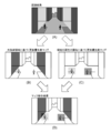
- FIG. 5 is a diagram showing projection processing using the projection map data.
- each region represented by different shades of gray scale shows the recognition result of Sema Seg. That is, it indicates that the same attribute was recognized for the portion colored with the same color.
- FIG. 6 is a diagram showing the calculation process of the unobserved region.
- the area attribute relationship determination unit 15 determines the relationship between the attributes of a plurality of areas in the captured image based on the projection sema-segment data based on the projection map data (step 108).
- the update priority map generation unit 16 generates an update priority map based on the relationship of the attributes of the determined area (step 109).
- FIG. 7 is a diagram for explaining the area attribute relationship determination process and the update priority map generation process.
- the area attribute relationship determination unit 15 is on the left side of the captured image. It is determined that the pedestrian area and the sidewalk area overlap, and that the pedestrian area and the road surface overlap on the right side of the captured image.
- the update priority map generation unit 16 lowers the update priority for the area because pedestrians / bicycles on the sidewalk are not expected to be in such a dangerous situation. Set.
- the update priority map generation unit 16 sets a high update priority for the area because pedestrians / bicycles on the road surface are assumed to be in a dangerous situation.
- FIG. 6C and the update priority map illustrated thereafter it is shown that the higher the density of gray, the higher the update priority.
- the update priority map generation unit 16 may set a high update priority because there is a risk that the boundary area between the sidewalk / road surface and other areas will be shaded and other objects will suddenly pop out. Good.
- the update priority map generation unit 16 is not limited to the relationship between the attributes of the two areas, and may generate the update priority map based on the relationship between the attributes of three or more areas.
- the update priority map generation unit 16 may change the movement of the pedestrian / bicycle area around the automobile area on the road surface in order to avoid the pedestrian / bicycle.
- the update priority may be set high.
- the update priority map generation unit 16 may change the movement of the plurality of pedestrians / bicycles on the road surface in order to avoid each other in the area where the plurality of pedestrians / bicycles are close to each other. , The update priority may be set high for that area.
- FIG. 8 is a flowchart showing a more detailed flow of the area attribute relationship determination process and the update priority map generation process. Further, FIG. 9 is a diagram showing an example of a priority table stored in the storage unit 7690 or the like for setting the update priority.
- the area attribute relationship determination unit 15 repeats the process of determining the attributes of the area around the area for all the areas recognized by Sema Seg in the above step 108.
- the update priority map generation unit 16 refers to the priority table shown in FIG. 9 based on the relationship between the attributes of the region and the surrounding regions for all the determined regions. Set the update priority of the area.
- the priority table shown in FIG. 9 the case where the attribute of the area of interest is a pedestrian is shown, and if the attribute of the surrounding area is a sidewalk, the priority is set low, and if the attribute is a road surface, the priority is set high. To. Further, as a peripheral area attribute, when a car or a pedestrian is detected other than the road surface, a higher priority is set. The priority in this case corresponds to the degree of risk (possibility of accident, etc.).
- the update priority map generation unit 16 has an update priority map based on the relationship between the update priority map based on the unobserved region generated in step 106 and the attributes of the region generated in step 109. (Step 110).
- FIG. 10 is a diagram showing the state of integration of the update priority map. From the Sema Seg result shown in Fig. (A), the update priority map shown in Fig. (B) is obtained based on the unobserved area, and the update priority shown in Fig. (C) is obtained based on the relationship of the attributes of the area. Suppose you get a map.
- the update priority map generation unit 16 integrates both update priority maps to generate an integrated update priority map as shown in FIG. 3D. As a result of the integration, the areas where the areas set in both update priority maps overlap each other are set to have higher priorities by adding the priorities in each update priority map.
- the update priority map generation unit 16 may set an area in which the detected unobserved area is slightly expanded prior to integration in order to improve the detection accuracy in the update priority map based on the unobserved area. Good.
- the update priority map generation unit 16 sets a wider area than the area where the pedestrian is detected prior to the integration in the update priority map based on the relationship of the area attributes in order to correspond to the movement of the pedestrian or the like. You may leave it.
- the area sema-seg unit 17 subsequently executes the sema-seg process of each area according to the update priority (update frequency) based on the integrated update priority map (step 111).
- FIG. 11 is a diagram showing an example of sema-segment processing based on the update priority map.
- the region sema-segment unit 17 sets an circumscribing rectangle of a region having a high priority as shown in FIG. Execute Sema Seg for the rectangular area.
- the region semasegment section 17 sets all the circumscribing rectangle regions. Execute the rectangle for.
- the semaseg is executed for the area with low update priority. It may be excluded from the target.
- the Sema Seg integration unit 18 integrates the Sema Seg result (step 107) after projection at time T and the region Sema Seg result (step 111), outputs integrated Sema Seg data, and performs a series of Sema Seg processing. Is completed (step 112).
- the integrated control unit 7600 of the vehicle control system 7000 does not uniformly execute the recognition process for each captured image (frame) to be acquired, but rather the region in the image.
- the execution frequency of the Sema Seg process based on the attributes, redundant processing can be eliminated and the amount of calculation can be reduced.
- the projection map generation unit 12 generates projection map data based on the distance data (z) for each captured image coordinate between the vehicle and the subject and the relative movement amount data (Rt) of the vehicle. It was generating. Instead, the projection map generation unit 12 may generate a projection map between the time (T-1) frame and the time (T) frame by using optical flow or block matching.
- the area attribute relationship determination unit 15 and the update priority map generation unit 16 set the update priority based on the relationship of the area attributes, but the update priority is set based on the attribute itself of each area. It may be set. For example, the update priority may be set low for the signal or sign area, or the update priority may be set higher for the bicycle area than the pedestrian and the automobile area than the bicycle in consideration of the moving speed. You may.
- the update priority map generation unit 16 generates an update priority map to be used for the semasegu by integrating the update priority map based on the unobserved area and the update priority map based on the relationship between the attributes of the area. It was.
- the update priority map generation unit 16 uses an update priority map generated using other parameters in addition to these two update priority maps and in place of either of the two update priority maps. You may. 12 to 14 are diagrams illustrating these update priority maps.
- the update priority map generation unit 16 may set the update priority according to the position of the region in the captured image.
- the update priority map generation unit 16 is centered on an image of an input frame as shown in FIG. 12 (A), which is close to the traveling direction of the vehicle as shown in FIG.
- the update priority may be set higher in the area of the unit, and the update priority may be set lower in the area of the edge of the image that is not in the traveling direction of the vehicle to generate the update priority map.
- the update priority map generation unit 16 may set, for example, the update priority at the upper part of the image higher than the update priority at the lower part of the image.
- the update priority map generation unit 16 may set the update priority according to the moving (running) speed of the vehicle and the position of the region in the captured image.
- the update priority map generation unit 16 travels at a high speed (for example, at a speed equal to or higher than a threshold value of 80 km / h or the like) when the input frame as shown in FIG. 13A is acquired.
- a high speed for example, at a speed equal to or higher than a threshold value of 80 km / h or the like
- the update priority of the area in the center of the image is set high, and the update priority of the edge of the image is given.
- the update priority map generation unit 16 is generally more important for the driver to look around than in front of the vehicle. As shown in C), the update priority of the area in the center of the image is set low, and the update priority of the area at the edge of the image is set low.
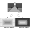
- the update priority map generation unit 16 may set the update priority according to the distance (z) between the subject and the vehicle in the captured image.
- the update priority map generation unit 16 when the update priority map generation unit 16 obtains the depth map as shown in FIG. 14 (B) for the input frame as shown in FIG. As shown in C), the update priority may be set higher for the area of the subject closer to the vehicle, and the update priority may be set lower for the subject farther from the vehicle.
- the update priority map generation unit 16 sets the update priority for the region of the captured image in which the reliability of the attribute recognition result by Sema Seg is low or the region where the attribute cannot be recognized by Sema Seg. It may be set high.
- the update priority map generation unit 16 can increase the possibility of recognizing the attribute by intensively executing the recognition process for the area whose attribute is unknown, for reasons such as a change in the composition of imaging later. it can.
- the area sema-seg unit 17 executes the sema-seg only for the area set by the update priority map generation unit 16 instead of the entire captured image.
- the region sema seg unit 17 may periodically execute the sema seg for the entire region of the captured image. As a result, errors due to partial recognition processing for each area are periodically supplemented.
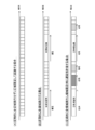
- FIG. 15 is a diagram showing an execution example of Sema Seg (hereinafter, all area processing) for the entire area in this case.
- FIG. (A) shows an example of time-series processing in the case where the periodic whole area processing is not executed as in the above-described embodiment.
- FIG. 6B when the whole area processing is periodically executed, the delay becomes large, but the recognition result after the whole area processing becomes highly accurate.
- the area sema-seg unit 17 may allow a delay when executing the sema-seg whose area is limited by the update priority while periodically executing the entire area processing. .. Although a delay occurs due to this, it is possible to process all the areas necessary for recognition without omitting the processing due to the calculation resource in the semasegu when the area is limited.
- the area sema-segment unit 17 may execute the entire area processing when the area of the unobserved area (the area that could not be projected by the projection map) is generated in a predetermined ratio or more.
- the region Sema Seg unit 17 executes the entire region processing while suppressing the increase in the amount of calculation. The recognition accuracy can be improved.
- the area sema-segment unit 17 may execute the entire area processing when the steering angle of the vehicle detected by the vehicle state detection unit 7110 is equal to or greater than a predetermined angle.
- a large steering angle is detected, the scenery to be imaged changes significantly and the unobserved region is considered to be large. Therefore, the region sema-segment unit 17 executes the entire region processing in such a case. It is possible to improve the recognition accuracy by omitting the calculation amount for detecting the unobserved area.
- the area sema seg unit 17 may execute the entire area processing when the vehicle is moving in a predetermined position.
- position information GPS information and map information acquired by the positioning unit 7640 are used.
- the area sema-segment unit 17 may execute the entire area processing when it detects that the vehicle is traveling on an uphill or a downhill with a gradient equal to or higher than a predetermined value.
- the area sema-segment unit 17 performs the entire area processing in such a case. By executing this, it is possible to improve the recognition accuracy by omitting the calculation amount for detecting the unobserved area.
- the area sema-segment unit 17 may execute the entire area processing because the scenery to be imaged changes significantly when the vehicle enters the tunnel and when the vehicle exits the tunnel.
- the entire area processing may be executed.
- the region sema seg unit 17 sets the circumscribing rectangle of the region having a high priority, and executes the sema seg for the region of the circumscribing rectangle.
- the method of setting the target area of Sema Seg is not limited to this.
- the area sema-seg unit 17 may set only the pixel area presumed to be necessary for the sema-seg calculation as the sema-seg target instead of the area cut out by the circumscribing rectangle.
- the area sema-segment unit 17 determines the region having a high priority shown in the update priority map as shown in the figure (C).
- the area required to obtain the result may be calculated back to set the sema-seg target area, and the sema-seg may be executed for the area.
- the area sema-seg unit 17 may exclude the low-priority area from the sema-seg target.
- the vehicle is shown as a moving body on which the integrated control unit 7600 as an information processing device is mounted, but an information processing device capable of processing the same information as the integrated control unit 7600 is provided.
- the moving body to be mounted is not limited to the vehicle.
- the information processing device is realized as a device mounted on a moving body of any kind such as a motorcycle, a bicycle, a personal mobility, an airplane, a drone, a ship, a robot, a construction machine, and an agricultural machine (tractor). May be good.
- the relationship of the above-mentioned attributes (pedestrian, vehicle, road surface, sidewalk, etc.) is also recognized differently depending on the moving body.
- the target on which the above information processing device is installed is not limited to moving objects.
- this technology can be applied to images captured by surveillance cameras.
- the processing associated with the movement of the vehicle described in the above-described embodiment is not executed, but since the imaging target may change with the pan / tilt / zoom of the surveillance camera, in addition to the attributes of the above area, it has not been executed.
- the present technology can have the following configurations.
- An image processing unit that executes recognition processing that recognizes the attributes of a predetermined area included in the images captured by the cameras that are sequentially acquired, and A control unit that sets the execution frequency of the recognition process based on the recognized attribute for the predetermined area.
- Information processing device equipped with (2) The information processing device according to (1) above.
- the image processing unit recognizes the attribute for each pixel of the captured image, and recognizes the attribute.
- the control unit is an information processing device that sets the execution frequency of the recognition process for each of the pixels.
- the image processing unit projects the result of the recognition process executed for each pixel of the past captured image onto each corresponding pixel of the current captured image.
- the control unit is an information processing device that sets the execution frequency low in a region where the recognition result is the same as the result of the projection.
- the image processing unit obtains distance information between the past captured image, the imaged object in the predetermined region in the current captured image, and the information processing apparatus, and the time of acquiring the past frame and the present. An information processing device that projects the result of the recognition process using the position information of the information processing device at the time of frame acquisition.
- the image processing unit is an information processing device that projects the result of the recognition process between the past frame and the current frame by using optical flow or block matching for the predetermined area.
- the information processing device according to any one of (1) to (5) above.
- the control unit is an information processing device that sets the execution frequency according to the relationship of attributes recognized for a plurality of regions included in the captured image. (7) The information processing device according to any one of (1) to (6) above.
- the control unit is an information processing device that sets the execution frequency according to the position of the predetermined region in the captured image. (8) The information processing device according to any one of (1) to (7) above.
- the control unit is an information processing device that sets the execution frequency according to the distance between the object to be imaged in the predetermined region and the information processing device. (9) The information processing device according to any one of (1) to (8) above.
- the control unit is an information processing device that sets the execution frequency according to the moving speed and the position of the moving body on which the information processing device is mounted.
- the control unit sets a high execution frequency of the recognition process for a region in the current captured image that could not be projected from the past captured image to the current captured image. apparatus.
- the control unit is an information processing device that sets a high execution frequency of the recognition process in an area where the reliability of the result of the recognition process is low or an area where the attribute cannot be recognized by the recognition process.
- the image processing unit is an information processing device that executes the recognition process at regular intervals for the entire region in the captured image. (13) The information processing device according to (12) above.
- the image processing unit projects the result of the recognition process executed for each pixel of the past captured image onto each corresponding pixel of the current captured image, and the area of the unprojectable region is generated by a predetermined ratio or more.
- an information processing device that executes the recognition process for the entire area in the captured image.
- the image processing unit is an information processing device that executes the recognition process for the entire area in the captured image when the steering angle of the moving body on which the information processing device is mounted becomes equal to or more than a predetermined angle.
- the image processing unit is an information processing device that executes the recognition process for the entire area in the captured image when the moving body on which the information processing device is mounted is moving at a predetermined position.
- the information processing device according to any one of (12) to (15) above. When the area of the region where the reliability of the result of the recognition processing is low or the region where the attribute cannot be recognized by the recognition processing occurs in a predetermined ratio or more, the image processing unit covers all the regions in the captured image.
- a recognition process is executed to recognize the attributes of a predetermined area included in the images captured by the cameras that are sequentially acquired.
Abstract
情報処理装置は、画像処理部と制御部とを有する。上記画像処理部は、順次取得されるカメラの撮像画像に含まれる所定の領域の属性を認識する認識処理を実行する。上記制御部は、上記所定の領域に対して、上記認識された属性に基づいて、上記認識処理の実行頻度を設定する。
Description
本技術は、撮像画像中から物体を認識する情報処理装置、情報処理方法及びプログラムに関する。
従来から、画像中から所定のオブジェクト領域を検出する技術が存在する。
下記特許文献1には、車両の周辺を撮像したフレーム画像のうち、基準時刻に取得した基準フレーム画像と基準時刻より過去に取得した過去フレーム画像との差分画像に基づいて車両の周辺に存在する障害物を検出する障害物検出装置が開示されている。
下記特許文献2には、撮影された複数の画像のうち対象画像と少なくとも1つの参照画像から、対象画像の各部分の動きベクトルを検出し、上記複数の画像のうち2つの画像刊の差分画像を算出し、上記動きベクトルと差分画像とに基づいて、物体が存在する物体領域を検出する物体検出装置が開示されている。
しかし、上記特許文献1及び2に記載の技術では、いずれも画像の全体同士の差分に基づいて物体を検出するため計算量が多くなり、また過去画像と類似した画像を処理することが多いため処理が冗長となってしまう。
以上のような事情に鑑み、本技術の目的は、画像認識処理における冗長処理をなくして,計算量を削減することが可能な情報処理装置、情報処理方法及びプログラムを提供することにある。
上記目的を達成するため、本技術の一形態に係る情報処理装置は、画像処理部と制御部とを有する。上記画像処理部は、順次取得されるカメラの撮像画像に含まれる所定の領域の属性を認識する認識処理を実行する。上記制御部は、上記所定の領域に対して、上記認識された属性に基づいて、上記認識処理の実行頻度を設定する。
この構成により情報処理装置は、取得される撮像画像(フレーム)毎に一律に認識処理を実行するのではなく、画像中の領域の属性に基づいて認識処理の実行頻度を設定することで、画像認識処理における冗長処理をなくして、計算量を削減することができる。ここで属性とは、例えば路面、歩道、歩行者、自動車、自転車、信号機、標識、街路樹といった被撮像物を識別するものであってもよい。
上記画像処理部は、上記撮像画像のピクセルごとに属性を認識し、上記制御部は、それぞれの上記ピクセルに対して上記認識処理の実行頻度を設定してもよい。
上記画像処理部は、過去の撮像画像の各ピクセルについて実行された認識処理の結果を現在の撮像画像の対応する各ピクセルに射影し、上記制御部は、上記射影の結果、認識結果が同一となる領域について上記実行頻度を低く設定してもよい。
これにより情報処理装置は、過去の認識結果を利用することで冗長処理を無くし計算量を削減することができ、また認識精度を安定させることができる。
この場合上記画像処理部は、上記過去の撮像画像と上記現在の撮像画像における上記所定の領域の被撮像物と当該情報処理装置との間の距離情報と、上記過去の撮像画像の取得時と上記現在の撮像画像の取得時における当該情報処理装置の位置情報を用いて上記認識処理の結果を射影してもよい。
またこれに代えて上記画像処理部は、上記過去の撮像画像と上記現在の撮像画像との間で上記所定の領域についてオプティカルフローまたはブロックマッチングを用いて上記認識処理の結果を射影してもよい。
上記制御部は、上記撮像画像に含まれる複数の領域について認識された属性の関係によって上記実行頻度を設定してもよい。
これにより情報処理装置は、撮像画像中の複数の領域の属性の関係性を判断することで例えば重要度を把握しそれに応じて実行頻度を設定することができる。ここで属性の関係を判断する複数の領域は、典型的には隣接する少なくとも2つの領域であり、例えば歩道、路面、人(歩行者)という各属性が認識された領域が存在する場合、歩道上の歩行者はそれほど危険ではないため当該歩行者の領域については実行頻度が低く設定される一方、路面上の歩行者は危険なため当該歩行者の領域については実行頻度が高く設定される。また路面上の自動車の周辺の歩行者の領域については実行頻度を高く設定するといったように、3つ以上領域の関係によって実行頻度が設定されてもよい。
上記制御部は、上記撮像画像内における上記所定の領域の位置に応じて上記実行頻度を設定してもよい。
これにより情報処理装置は、例えば撮像画像の中央部の領域の更新頻度を端部の領域の更新頻度よりも高く設定する等、位置に応じた更新頻度の設定により計算量を削減することができる。
上記制御部は、上記所定の領域の被撮像物と当該情報処理装置との間の距離に応じて上記実行頻度を設定してもよい。
これにより情報処理装置は、例えば情報処理装置から近い領域の更新頻度を遠い領域の更新頻度よりも高く設定する等、距離に応じた更新頻度の設定により計算量を削減することができる。
上記制御部は、当該情報処理装置が搭載された移動体の移動速度と上記位置に応じて上記実行頻度を設定してもよい。
これにより情報処理装置は、例えば高速移動中は画像中央の領域の更新頻度を画像端部の領域の更新頻度よりも高く設定し、低速移動中は画像中央の領域の更新頻度を画像端部の領域の更新頻度よりも低く設定する等、移動速度の変化に伴う重要領域の変化に対応することができる。
上記制御部は、上記現在の撮像画像内の領域のうち、上記過去の撮像画像から上記現在の撮像画像へ射影できなかった領域に対して、上記認識処理の上記実行頻度を高く設定してもよい。
これにより情報処理装置は、直前の撮像画像では観測されなかった領域の認識処理の実行頻度を高くすることで、既に観測された領域の認識処理に要する計算量を削減することができる。
上記制御部は、上記認識処理の結果の信頼度が低い領域または上記認識処理によって上記属性を認識できなかった領域に対して、上記認識処理の実行頻度を高く設定してもよい。
ここで、信頼度は認識処理の結果の正しさを示すものであり、信頼度は例えば、当該情報処理装置が搭載された移動体から撮像画像における所定の領域の被撮像物までの距離によって、当該情報処理装置が搭載された移動体の速度によって、撮像装置の解像度等の性能によって、被撮像物同士の重なり合いや位置関係によって、天候によって、撮像画像の明度によって、被撮像物が撮像された時間によって、などの方法により設定されてもよい。
これにより、属性が不明な領域について重点的に認識処理を実行することで、後に属性を認識できる可能性を高めることができる。
上記画像処理部は、上記撮像画像内の全領域に対して一定周期で上記認識処理を実行してもよい。
これにより情報処理装置は、領域毎の部分的な認識処理によるエラーを定期的に補完することができる。
上記画像処理部は、過去の撮像画像の各ピクセルについて実行された認識処理の結果を現在の撮像画像の対応する各ピクセルに射影し、上記射影できなかった領域の面積が所定の割合以上発生した場合に、上記撮像画像内の全領域に対して上記認識処理を実行してもよい。
これにより情報処理装置は、現在の撮像画像において過去の撮像画像で未観測の領域が多い場合には、撮像画像の全領域について認識処理を実行することで、計算量の増加を抑えながらも認識精度を高めることができる。
上記画像処理部は、当該情報処理装置が搭載された移動体の操舵角が所定の角度以上となった場合に、上記撮像画像内の全領域に対して上記認識処理を実行してもよい。
これにより情報処理装置は、大きな操舵角を検出した場合には撮像対象も大きく変化すると考えられることから、撮像画像の全領域について認識処理を実行することで、過去の撮像画像で未観測の領域を検出することなく認識精度を高めることができる。
上記画像処理部は、当該情報処理装置が搭載された移動体が所定の位置を移動している場合に、上記撮像画像内の全領域に対して上記認識処理を実行してもよい。
これにより情報処理装置は、例えば急な坂やトンネル内等、撮像対象が大きく変化する位置の移動中は、撮像画像の全領域について認識処理を実行することで、過去の撮像画像で未観測の領域を検出することなく認識精度を高めることができる。
上記画像処理部は、上記認識処理の結果の信頼度が低い領域または上記認識処理によって上記属性を認識できなかった領域の面積が所定の割合以上発生した場合に、上記撮像画像内の全領域に対して上記認識処理を実行してもよい。
これにより情報処理装置は、属性が不明な領域が多い場合には、撮像画像の全領域について認識処理を実行することで、計算量の増加を抑えながらも認識精度を高めることができる。
本技術の他の形態に係る情報処理方法は、
順次取得されるカメラの撮像画像に含まれる所定の領域の属性を認識する認識処理を実行し、
上記所定の領域に対して、上記認識された属性に基づいて、上記認識処理の実行頻度を設定する、ことを含む。
順次取得されるカメラの撮像画像に含まれる所定の領域の属性を認識する認識処理を実行し、
上記所定の領域に対して、上記認識された属性に基づいて、上記認識処理の実行頻度を設定する、ことを含む。
本技術の他の形態に係るプログラムは、情報処理装置に、
順次取得されるカメラの撮像画像に含まれる所定の領域の属性を認識する認識処理を実行するステップと、
上記所定の領域に対して、上記認識された属性に基づいて、上記認識処理の実行頻度を設定するステップと、を実行させる。
順次取得されるカメラの撮像画像に含まれる所定の領域の属性を認識する認識処理を実行するステップと、
上記所定の領域に対して、上記認識された属性に基づいて、上記認識処理の実行頻度を設定するステップと、を実行させる。
以上のように、本技術によれば、画像認識処理における冗長処理をなくして、計算量を削減することができる。しかし、当該効果は本技術を限定するものではない。
以下、本技術に係る実施形態を、図面を参照しながら説明する。
[車両制御システムの構成]
図1は、本開示に係る技術が適用され得る移動体制御システムの一例である車両制御システム7000の概略的な構成例を示すブロック図である。車両制御システム7000は、通信ネットワーク7010を介して接続された複数の電子制御ユニットを備える。図1に示した例では、車両制御システム7000は、駆動系制御ユニット7100、ボディ系制御ユニット7200、バッテリ制御ユニット7300、車外情報検出ユニット7400、車内情報検出ユニット7500、及び統合制御ユニット7600を備える。これらの複数の制御ユニットを接続する通信ネットワーク7010は、例えば、CAN(Controller Area Network)、LIN(Local Interconnect Network)、LAN(Local Area Network)又はFlexRay(登録商標)等の任意の規格に準拠した車載通信ネットワークであってよい。
各制御ユニットは、各種プログラムにしたがって演算処理を行うマイクロコンピュータと、マイクロコンピュータにより実行されるプログラム又は各種演算に用いられるパラメータ等を記憶する記憶部と、各種制御対象の装置を駆動する駆動回路とを備える。各制御ユニットは、通信ネットワーク7010を介して他の制御ユニットとの間で通信を行うためのネットワークI/Fを備えるとともに、車内外の装置又はセンサ等との間で、有線通信又は無線通信により通信を行うための通信I/Fを備える。図1では、統合制御ユニット7600の機能構成として、マイクロコンピュータ7610、汎用通信I/F7620、専用通信I/F7630、測位部7640、ビーコン受信部7650、車内機器I/F7660、音声画像出力部7670、車載ネットワークI/F7680及び記憶部7690が図示されている。他の制御ユニットも同様に、マイクロコンピュータ、通信I/F及び記憶部等を備える。
駆動系制御ユニット7100は、各種プログラムにしたがって車両の駆動系に関連する装置の動作を制御する。例えば、駆動系制御ユニット7100は、内燃機関又は駆動用モータ等の車両の駆動力を発生させるための駆動力発生装置、駆動力を車輪に伝達するための駆動力伝達機構、車両の舵角を調節するステアリング機構、及び、車両の制動力を発生させる制動装置等の制御装置として機能する。駆動系制御ユニット7100は、ABS(Antilock Brake System)又はESC(Electronic Stability Control)等の制御装置としての機能を有してもよい。
駆動系制御ユニット7100には、車両状態検出部7110が接続される。車両状態検出部7110には、例えば、車体の軸回転運動の角速度を検出するジャイロセンサ、車両の加速度を検出する加速度センサ、あるいは、アクセルペダルの操作量、ブレーキペダルの操作量、ステアリングホイールの操舵角、エンジン回転数又は車輪の回転速度等を検出するためのセンサのうちの少なくとも一つが含まれる。駆動系制御ユニット7100は、車両状態検出部7110から入力される信号を用いて演算処理を行い、内燃機関、駆動用モータ、電動パワーステアリング装置又はブレーキ装置等を制御する。
ボディ系制御ユニット7200は、各種プログラムにしたがって車体に装備された各種装置の動作を制御する。例えば、ボディ系制御ユニット7200は、キーレスエントリシステム、スマートキーシステム、パワーウィンドウ装置、あるいは、ヘッドランプ、バックランプ、ブレーキランプ、ウィンカー又はフォグランプ等の各種ランプの制御装置として機能する。この場合、ボディ系制御ユニット7200には、鍵を代替する携帯機から発信される電波又は各種スイッチの信号が入力され得る。ボディ系制御ユニット7200は、これらの電波又は信号の入力を受け付け、車両のドアロック装置、パワーウィンドウ装置、ランプ等を制御する。
バッテリ制御ユニット7300は、各種プログラムにしたがって駆動用モータの電力供給源である二次電池7310を制御する。例えば、バッテリ制御ユニット7300には、二次電池7310を備えたバッテリ装置から、バッテリ温度、バッテリ出力電圧又はバッテリの残存容量等の情報が入力される。バッテリ制御ユニット7300は、これらの信号を用いて演算処理を行い、二次電池7310の温度調節制御又はバッテリ装置に備えられた冷却装置等の制御を行う。
車外情報検出ユニット7400は、車両制御システム7000を搭載した車両の外部の情報を検出する。例えば、車外情報検出ユニット7400には、撮像部7410及び車外情報検出部7420のうちの少なくとも一方が接続される。撮像部7410には、ToF(Time Of Flight)カメラ、ステレオカメラ、単眼カメラ、赤外線カメラ及びその他のカメラのうちの少なくとも一つが含まれる。車外情報検出部7420には、例えば、現在の天候又は気象を検出するための環境センサ、あるいは、車両制御システム7000を搭載した車両の周囲の他の車両、障害物又は歩行者等を検出するための周囲情報検出センサのうちの少なくとも一つが含まれる。
環境センサは、例えば、雨天を検出する雨滴センサ、霧を検出する霧センサ、日照度合いを検出する日照センサ、及び降雪を検出する雪センサのうちの少なくとも一つであってよい。周囲情報検出センサは、超音波センサ、レーダ装置及びLIDAR(Light Detection and Ranging、Laser Imaging Detection and Ranging)装置のうちの少なくとも一つであってよい。これらの撮像部7410及び車外情報検出部7420は、それぞれ独立したセンサないし装置として備えられてもよいし、複数のセンサないし装置が統合された装置として備えられてもよい。
ここで、図2は、撮像部7410及び車外情報検出部7420の設置位置の例を示す。撮像部7910,7912,7914,7916,7918は、例えば、車両7900のフロントノーズ、サイドミラー、リアバンパ、バックドア及び車室内のフロントガラスの上部のうちの少なくとも一つの位置に設けられる。フロントノーズに備えられる撮像部7910及び車室内のフロントガラスの上部に備えられる撮像部7918は、主として車両7900の前方の画像を取得する。サイドミラーに備えられる撮像部7912,7914は、主として車両7900の側方の画像を取得する。リアバンパ又はバックドアに備えられる撮像部7916は、主として車両7900の後方の画像を取得する。車室内のフロントガラスの上部に備えられる撮像部7918は、主として先行車両又は、歩行者、障害物、信号機、交通標識又は車線等の検出に用いられる。
なお、図2には、それぞれの撮像部7910,7912,7914,7916の撮影範囲の一例が示されている。撮像範囲aは、フロントノーズに設けられた撮像部7910の撮像範囲を示し、撮像範囲b,cは、それぞれサイドミラーに設けられた撮像部7912,7914の撮像範囲を示し、撮像範囲dは、リアバンパ又はバックドアに設けられた撮像部7916の撮像範囲を示す。例えば、撮像部7910,7912,7914,7916で撮像された画像データが重ね合わせられることにより、車両7900を上方から見た俯瞰画像が得られる。
車両7900のフロント、リア、サイド、コーナ及び車室内のフロントガラスの上部に設けられる車外情報検出部7920,7922,7924,7926,7928,7930は、例えば超音波センサ又はレーダ装置であってよい。車両7900のフロントノーズ、リアバンパ、バックドア及び車室内のフロントガラスの上部に設けられる車外情報検出部7920,7926,7930は、例えばLIDAR装置であってよい。これらの車外情報検出部7920~7930は、主として先行車両、歩行者又は障害物等の検出に用いられる。
図1に戻って説明を続ける。車外情報検出ユニット7400は、撮像部7410に車外の画像を撮像させるとともに、撮像された画像データを受信する。また、車外情報検出ユニット7400は、接続されている車外情報検出部7420から検出情報を受信する。車外情報検出部7420が超音波センサ、レーダ装置又はLIDAR装置である場合には、車外情報検出ユニット7400は、超音波又は電磁波等を発信させるとともに、受信された反射波の情報を受信する。車外情報検出ユニット7400は、受信した情報に基づいて、人、車、障害物、標識又は路面上の文字等の物体検出処理又は距離検出処理を行ってもよい。車外情報検出ユニット7400は、受信した情報に基づいて、降雨、霧又は路面状況等を認識する環境認識処理を行ってもよい。車外情報検出ユニット7400は、受信した情報に基づいて、車外の物体までの距離を算出してもよい。
また、車外情報検出ユニット7400は、受信した画像データに基づいて、人、車、障害物、標識又は路面上の文字等を認識する画像認識処理又は距離検出処理を行ってもよい。車外情報検出ユニット7400は、受信した画像データに対して歪補正又は位置合わせ等の処理を行うとともに、異なる撮像部7410により撮像された画像データを合成して、俯瞰画像又はパノラマ画像を生成してもよい。車外情報検出ユニット7400は、異なる撮像部7410により撮像された画像データを用いて、視点変換処理を行ってもよい。
車内情報検出ユニット7500は、車内の情報を検出する。車内情報検出ユニット7500には、例えば、運転者の状態を検出する運転者状態検出部7510が接続される。運転者状態検出部7510は、運転者を撮像するカメラ、運転者の生体情報を検出する生体センサ又は車室内の音声を集音するマイク等を含んでもよい。生体センサは、例えば、座面又はステアリングホイール等に設けられ、座席に座った搭乗者又はステアリングホイールを握る運転者の生体情報を検出する。車内情報検出ユニット7500は、運転者状態検出部7510から入力される検出情報に基づいて、運転者の疲労度合い又は集中度合いを算出してもよいし、運転者が居眠りをしていないかを判別してもよい。車内情報検出ユニット7500は、集音された音声信号に対してノイズキャンセリング処理等の処理を行ってもよい。
統合制御ユニット7600は、各種プログラムにしたがって車両制御システム7000内の動作全般を制御する。統合制御ユニット7600には、入力部7800が接続されている。入力部7800は、例えば、タッチパネル、ボタン、マイクロフォン、スイッチ又はレバー等、搭乗者によって入力操作され得る装置によって実現される。統合制御ユニット7600には、マイクロフォンにより入力される音声を音声認識することにより得たデータが入力されてもよい。入力部7800は、例えば、赤外線又はその他の電波を利用したリモートコントロール装置であってもよいし、車両制御システム7000の操作に対応した携帯電話又はPDA(Personal Digital Assistant)等の外部接続機器であってもよい。入力部7800は、例えばカメラであってもよく、その場合搭乗者はジェスチャにより情報を入力することができる。あるいは、搭乗者が装着したウェアラブル装置の動きを検出することで得られたデータが入力されてもよい。さらに、入力部7800は、例えば、上記の入力部7800を用いて搭乗者等により入力された情報に基づいて入力信号を生成し、統合制御ユニット7600に出力する入力制御回路などを含んでもよい。搭乗者等は、この入力部7800を操作することにより、車両制御システム7000に対して各種のデータを入力したり処理動作を指示したりする。
記憶部7690は、マイクロコンピュータにより実行される各種プログラムを記憶するROM(Read Only Memory)、及び各種パラメータ、演算結果又はセンサ値等を記憶するRAM(Random Access Memory)を含んでいてもよい。また、記憶部7690は、HDD(Hard Disc Drive)等の磁気記憶デバイス、半導体記憶デバイス、光記憶デバイス又は光磁気記憶デバイス等によって実現してもよい。
汎用通信I/F7620は、外部環境7750に存在する様々な機器との間の通信を仲介する汎用的な通信I/Fである。汎用通信I/F7620は、GSM(登録商標)(Global System of Mobile communications)、WiMAX(登録商標)、LTE(登録商標)(Long Term Evolution)若しくはLTE-A(LTE-Advanced)などのセルラー通信プロトコル、又は無線LAN(Wi-Fi(登録商標)ともいう)、Bluetooth(登録商標)などのその他の無線通信プロトコルを実装してよい。汎用通信I/F7620は、例えば、基地局又はアクセスポイントを介して、外部ネットワーク(例えば、インターネット、クラウドネットワーク又は事業者固有のネットワーク)上に存在する機器(例えば、アプリケーションサーバ又は制御サーバ)へ接続してもよい。また、汎用通信I/F7620は、例えばP2P(Peer To Peer)技術を用いて、車両の近傍に存在する端末(例えば、運転者、歩行者若しくは店舗の端末、又はMTC(Machine Type Communication)端末)と接続してもよい。
専用通信I/F7630は、車両における使用を目的として策定された通信プロトコルをサポートする通信I/Fである。専用通信I/F7630は、例えば、下位レイヤのIEEE802.11pと上位レイヤのIEEE1609との組合せであるWAVE(Wireless Access in Vehicle Environment)、DSRC(Dedicated Short Range Communications)、又はセルラー通信プロトコルといった標準プロトコルを実装してよい。専用通信I/F7630は、典型的には、車車間(Vehicle to Vehicle)通信、路車間(Vehicle to Infrastructure)通信、車両と家との間(Vehicle to Home)の通信及び歩車間(Vehicle to Pedestrian)通信のうちの1つ以上を含む概念であるV2X通信を遂行する。
測位部7640は、例えば、GNSS(Global Navigation Satellite System)衛星からのGNSS信号(例えば、GPS(Global Positioning System)衛星からのGPS信号)を受信して測位を実行し、車両の緯度、経度及び高度を含む位置情報を生成する。なお、測位部7640は、無線アクセスポイントとの信号の交換により現在位置を特定してもよく、又は測位機能を有する携帯電話、PHS若しくはスマートフォンといった端末から位置情報を取得してもよい。
ビーコン受信部7650は、例えば、道路上に設置された無線局等から発信される電波あるいは電磁波を受信し、現在位置、渋滞、通行止め又は所要時間等の情報を取得する。なお、ビーコン受信部7650の機能は、上述した専用通信I/F7630に含まれてもよい。
車内機器I/F7660は、マイクロコンピュータ7610と車内に存在する様々な車内機器7760との間の接続を仲介する通信インタフェースである。車内機器I/F7660は、無線LAN、Bluetooth(登録商標)、NFC(Near Field Communication)又はWUSB(Wireless USB)といった無線通信プロトコルを用いて無線接続を確立してもよい。また、車内機器I/F7660は、図示しない接続端子(及び、必要であればケーブル)を介して、USB(Universal Serial Bus)、HDMI(登録商標)(High-Definition Multimedia Interface、又はMHL(Mobile High-definition Link)等の有線接続を確立してもよい。車内機器7760は、例えば、搭乗者が有するモバイル機器若しくはウェアラブル機器、又は車両に搬入され若しくは取り付けられる情報機器のうちの少なくとも1つを含んでいてもよい。また、車内機器7760は、任意の目的地までの経路探索を行うナビゲーション装置を含んでいてもよい。車内機器I/F7660は、これらの車内機器7760との間で、制御信号又はデータ信号を交換する。
車載ネットワークI/F7680は、マイクロコンピュータ7610と通信ネットワーク7010との間の通信を仲介するインタフェースである。車載ネットワークI/F7680は、通信ネットワーク7010によりサポートされる所定のプロトコルに則して、信号等を送受信する。
統合制御ユニット7600のマイクロコンピュータ7610は、汎用通信I/F7620、専用通信I/F7630、測位部7640、ビーコン受信部7650、車内機器I/F7660及び車載ネットワークI/F7680のうちの少なくとも一つを介して取得される情報に基づき、各種プログラムにしたがって、車両制御システム7000を制御する。例えば、マイクロコンピュータ7610は、取得される車内外の情報に基づいて、駆動力発生装置、ステアリング機構又は制動装置の制御目標値を演算し、駆動系制御ユニット7100に対して制御指令を出力してもよい。例えば、マイクロコンピュータ7610は、車両の衝突回避あるいは衝撃緩和、車間距離に基づく追従走行、車速維持走行、車両の衝突警告、又は車両のレーン逸脱警告等を含むADAS(Advanced Driver Assistance System)の機能実現を目的とした協調制御を行ってもよい。また、マイクロコンピュータ7610は、取得される車両の周囲の情報に基づいて駆動力発生装置、ステアリング機構又は制動装置等を制御することにより、運転者の操作に拠らずに自律的に走行する自動運転等を目的とした協調制御を行ってもよい。
マイクロコンピュータ7610は、汎用通信I/F7620、専用通信I/F7630、測位部7640、ビーコン受信部7650、車内機器I/F7660及び車載ネットワークI/F7680のうちの少なくとも一つを介して取得される情報に基づき、車両と周辺の構造物や人物等の物体との間の3次元距離情報を生成し、車両の現在位置の周辺情報を含むローカル地図情報を作成してもよい。また、マイクロコンピュータ7610は、取得される情報に基づき、車両の衝突、歩行者等の近接又は通行止めの道路への進入等の危険を予測し、警告用信号を生成してもよい。警告用信号は、例えば、警告音を発生させたり、警告ランプを点灯させたりするための信号であってよい。
音声画像出力部7670は、車両の搭乗者又は車外に対して、視覚的又は聴覚的に情報を通知することが可能な出力装置へ音声及び画像のうちの少なくとも一方の出力信号を送信する。図1の例では、出力装置として、オーディオスピーカ7710、表示部7720及びインストルメントパネル7730が例示されている。表示部7720は、例えば、オンボードディスプレイ及びヘッドアップディスプレイの少なくとも一つを含んでいてもよい。表示部7720は、AR(Augmented Reality)表示機能を有していてもよい。出力装置は、これらの装置以外の、ヘッドホン、搭乗者が装着する眼鏡型ディスプレイ等のウェアラブルデバイス、プロジェクタ又はランプ等の他の装置であってもよい。出力装置が表示装置の場合、表示装置は、マイクロコンピュータ7610が行った各種処理により得られた結果又は他の制御ユニットから受信された情報を、テキスト、イメージ、表、グラフ等、様々な形式で視覚的に表示する。また、出力装置が音声出力装置の場合、音声出力装置は、再生された音声データ又は音響データ等からなるオーディオ信号をアナログ信号に変換して聴覚的に出力する。
なお、図1に示した例において、通信ネットワーク7010を介して接続された少なくとも二つの制御ユニットが一つの制御ユニットとして一体化されてもよい。あるいは、個々の制御ユニットが、複数の制御ユニットにより構成されてもよい。さらに、車両制御システム7000が、図示されていない別の制御ユニットを備えてもよい。また、上記の説明において、いずれかの制御ユニットが担う機能の一部又は全部を、他の制御ユニットに持たせてもよい。つまり、通信ネットワーク7010を介して情報の送受信がされるようになっていれば、所定の演算処理が、いずれかの制御ユニットで行われるようになってもよい。同様に、いずれかの制御ユニットに接続されているセンサ又は装置が、他の制御ユニットに接続されるとともに、複数の制御ユニットが、通信ネットワーク7010を介して相互に検出情報を送受信してもよい。
また本実施形態では、統合制御ユニット7600は、撮像部7410による撮像画像のピクセルごとに路面/歩道/歩行者/建物等の属性を認識するセマンティックセグメンテーション(セマセグ)を実行可能である。
セマンティックセグメンテーションは、様々な実際のオブジェクトの形状、その他の
特徴情報に基づくオブジェクト識別用の辞書データ(学習済みデータ)と、撮影画像内のオブジェクトとの一致度に基づいて、画像内のオブジェクトが何であるかのオブジェクト識別を行う技術である。セマンティックセグメンテーションでは撮影画像の画素(ピクセル)単位で物体識別を行う。
特徴情報に基づくオブジェクト識別用の辞書データ(学習済みデータ)と、撮影画像内のオブジェクトとの一致度に基づいて、画像内のオブジェクトが何であるかのオブジェクト識別を行う技術である。セマンティックセグメンテーションでは撮影画像の画素(ピクセル)単位で物体識別を行う。
[車両制御システムの機能ブロック構成]
図3は、上記統合制御ユニット7600に実装されたコンピュータプログラムの機能ブロック構成を示した図である。当該コンピュータプログラムは、それが格納されたコンピュータ読み取り可能な記録媒体として提供されてもよい。記録媒体は、例えば、磁気ディスク、光ディスク、光磁気ディスク、フラッシュメモリ等である。また、当該コンピュータプログラムは、記録媒体を用いずに、例えばネットワークを介して配信されてもよい。
図3は、上記統合制御ユニット7600に実装されたコンピュータプログラムの機能ブロック構成を示した図である。当該コンピュータプログラムは、それが格納されたコンピュータ読み取り可能な記録媒体として提供されてもよい。記録媒体は、例えば、磁気ディスク、光ディスク、光磁気ディスク、フラッシュメモリ等である。また、当該コンピュータプログラムは、記録媒体を用いずに、例えばネットワークを介して配信されてもよい。
本実施形態において、統合制御ユニット7600は、撮像部7410から順次取得される撮像画像について、そのピクセルごとに属性(車両/路面/歩道/歩行者/建物等)を認識するセマンティックセグメンテーション(セマセグ)を実行可能である。当該セマセグにより、撮像画像に含まれる被写体領域ごとに属性が認識されることになる。
統合制御ユニット7600は、当該認識処理の実行頻度(更新頻度)及びその対象となる領域を、当該属性に基づいて設定することができる。なお、当該処理に際し、一連の撮像画像のうち最初の撮像画像についてはその全体についてセマセグが実行され、それ以降の撮像画像について領域ごとに更新頻度が設定される。
図3に示すように、統合制御ユニット7600は、機能ブロックとして、相対移動推定部11、射影マップ生成部12、セマセグ射影部13、未観測領域設定部14、領域属性関係判定部15、更新優先度マップ生成部16、領域セマセグ部17及びセマセグ統合部18を有する。
相対移動推定部11は、測位部7640が生成した車両(撮像部7410)の時刻(T-1)及び時刻(T)における各位置情報を基に、車両の相対移動量データ(Rt)を生成して射影マップ生成部12へ出力する。
射影マップ生成部12は、車外情報検出ユニット7400が検出した時刻(T-1)における車両と被写体との間の撮像画像座標ごとの距離データ(z)と、上記相対移動推定部11から受信した相対移動量データ(Rt)とを基に、射影マップデータを生成してセマセグ射影部13及び未観測領域設定部14へ出力する。
具体的には、射影マップ生成部12は、撮像画像座標ごとの上記距離データ(z)の全撮像画像座標分の集合(デプス画像データ)を3次元の点群データに変換し、当該点群データを、上記相対移動量データ(Rt)を用いて座標変換する。そして射影マップ生成部12は、座標変換後の点群データを撮像画像平面に射影したデプス画像データを生成し、当該デプス画像データ中の距離データ(z)及び時刻(T-1)における画像座標を基に、時刻(T)の撮像画像に時刻(T-1)の撮像画像の画素ごとの画像認識(セマセグ)結果を示す値を射影するための射影元の位置を示す射影マップデータを生成する。
セマセグ射影部13は、上記射影マップ生成部12から受信した射影マップデータと、時刻(T-1)におけるセマセグ結果を基に、時刻(T)における撮像画像に当該セマセグ結果を射影した射影セマセグデータを生成し、セマセグ統合部18へ出力する。
未観測領域設定部14は、上記射影マップ生成部12から受信した射影マップデータを基に、時刻(T)における撮像画像に時刻(T-1)におけるセマセグ結果を射影できない領域、すなわち射影マップデータ中の、射影元の位置が示されていない未観測領域を検出し、それを示すデータを更新優先度マップ生成部16へ出力する。
領域属性関係判定部15は、撮像画像に含まれる複数の領域について上記セマセグによって認識された属性の関係を判定する。例えば領域属性関係判定部15は、歩道/路面領域と歩行者/自転車領域とが重なっている場合には、歩道/路面上に歩行者/自転車が存在すると判定する。
更新優先度マップ生成部16は、上記未観測領域設定部14で検出された未観測領域及び上記領域属性関係判定部15で判定された領域属性関係に基づいて、撮像画像の各領域に対してセマセグの更新の優先度(更新頻度)が設定された更新優先度マップを生成する。
更新優先度マップ生成部16は、例えば、未観測領域については更新優先度を高く設定し、また歩道上の歩行者の領域については更新優先度を低く、路面上の歩行者の領域については更新優先度を高く設定する。
領域セマセグ部17は、上記生成された更新優先度マップに基づいて、時刻(T)における撮像画像に対して領域毎のセマセグを実行し、その結果をセマセグ統合部18へ出力する。
セマセグ統合部18は、上記セマセグ射影部13から受信した時刻(T)における射影セマセグデータと、領域セマセグ部17から受信した時刻(T)における領域セマセグデータとを統合して、時刻(T)における撮像画像全体のセマセグ結果データを出力する。
このセマセグ結果データは、例えば、ADASの機能実現を目的とした協調制御や自動運転等を目的とした協調制御等に用いられ得る。
これら機能ブロック(コンピュータプログラム)は、統合制御ユニット7600ではなく上記車外情報検出ユニット7400に実装されてもよい。この場合車外情報検出ユニットから出力されたセマセグ結果データを基に統合制御ユニット7600によって上記ADASや自動運転のための協調制御が実行される。
[車両制御システムの動作]
次に、以上のように構成された車両制御システムの動作について説明する。当該動作は、上記統合制御ユニット7600のマイクロコンピュータ7600及び車載ネットワークインタフェース7680、専用通信インタフェース7630等のハードウェアと、記憶部1690等に記憶されたソフトウェア(図3に示す各機能ブロック)との協働により実行される。
次に、以上のように構成された車両制御システムの動作について説明する。当該動作は、上記統合制御ユニット7600のマイクロコンピュータ7600及び車載ネットワークインタフェース7680、専用通信インタフェース7630等のハードウェアと、記憶部1690等に記憶されたソフトウェア(図3に示す各機能ブロック)との協働により実行される。
図4は、上記車両制御システムによる画像認識処理の流れを示したフローチャートである。
同図に示すように、まず相対移動推定部11が、時刻(T-1)及び時刻(T)における車両の位置情報を取得し(ステップ101)し、時刻(T-1)から時刻(T)までの間の車両(撮像部)の相対移動距離を推定する(ステップ102)。
続いて射影マップ生成部12が、時刻(T-1)の撮像画像における車両と被写体との距離データを取得し(ステップ103)、当該距離データと上記相対移動距離データを基に射影マップデータを生成する(ステップ104)。
続いて未観測領域設定部14が、射影マップデータを基に、時刻(T)の撮像画像における時刻(T-1)の撮像画像と比較した未観測領域を算出し(ステップ105)、当該未観測領域の更新優先度を高く設定した更新優先度マップを生成する(ステップ106)。
続いてセマセグ射影部13が、上記射影マップデータを基に、時刻(T-1)におけるセマセグ結果を時刻(T)における撮像画像に射影する(ステップ107)。
図5は、当該射影マップデータを用いた射影処理を示した図である。同図(B1)及び(B2)並びに以降の図面において濃淡の異なるグレースケールで表現された各領域は上記セマセグの認識結果を示す。すなわち、同一の色で着色された箇所について同一の属性が認識されたことを示す。
同図に示すように、時刻T=0において同図(A1)に示す位置を走行中の車両が時刻T=1において同図(A2)に示す位置へ移動した場合、時刻T=0の入力フレーム(B0)における各画素が時刻T=1の入力フレームのどの画素に対応するかが上記位置情報及び距離情報から全画素について判明したとする。
この場合、時刻T=1の入力フレームのセマセグ結果(B1)が、同図(B2)に示すように、時刻T=1の入力フレームの全領域に亘って射影されていることが分かる。これにより、時刻T=1の入力フレームについてセマセグを実行する冗長処理が削減され、計算量が削減されると共に、認識精度(安定性)が向上する。
図6は、未観測領域の算出処理を示した図である。同図(B2)に示すように、時刻T=0において同図(A1)に示す位置を走行中の車両が時刻T=1において同図(A2)に示す位置へ移動した場合、上記図5の場合とは異なり、時刻T=1の入力フレーム中に、時刻T=0の入力フレーム(B0)のセマセグ結果(B1)が射影できない未観測領域Rが生じている。
このように、カメラの構図によって、次のフレームへセマセグ結果が全て射影できる場合と部分的に射影できない未観測領域が生じる場合とがある。
図4に戻り、領域属性関係判定部15は、射影マップデータに基づく射影セマセグデータを基に、撮像画像中の複数の領域の属性の関係を判定する(ステップ108)。
続いて更新優先度マップ生成部16は、当該判定された領域の属性の関係を基に、更新優先度マップを生成する(ステップ109)。
図7は、領域属性関係判定処理及び更新優先度マップ生成処理を説明するための図である。
同図(A)に示す時刻(T-1)のセマセグ結果が、同図(B)に示す時刻(T)のセマセグ結果として射影された場合、領域属性関係判定部15は、撮像画像左側において歩行者領域と歩道領域とが重なっていることを判定し、また撮像画像右側において歩行者領域と路面とが重なっていることを判定する。
この場合、更新優先度マップ生成部16は、同図(C)に示すように、歩道上の歩行者/自転車は、それほど危険な状況は想定されないことから、その領域については更新優先度を低く設定する。
一方、更新優先度マップ生成部16は、路面上の歩行者/自転車は危険な状況が想定されるため、その領域については更新優先度を高く設定する。なお、同図(C)及びこれ以降に図示される更新優先度マップにおいては、グレーの濃度が高い程、更新優先度が高いことを示している。
その他、更新優先度マップ生成部16は、歩道/路面と他の領域との境界領域は、物陰になり他の物体が急に飛び出してくる危険性があるため更新優先度を高く設定してもよい。
また更新優先度マップ生成部16は、2つの領域の属性の関係に限らず、3つ以上の領域の属性の関係を基に更新優先度マップを生成してもよい。
例えば、更新優先度マップ生成部16は、路面上の自動車領域の周辺の歩行者/自転車の領域は、自動車が歩行者/自転車を回避するために動きを変化させる可能性があるため、その領域について更新優先度を高く設定してもよい。
また更新優先度マップ生成部16は、路面上の複数の歩行者/自転車が近接している領域は、それら複数の歩行者/自転車がお互いの回避のために動きを変化させる可能性があるため、その領域について更新優先度を高く設定してもよい。
図8は、上記領域属性関係判定処理及び更新優先度マップ生成処理のより詳細な流れを示したフローチャートである。また図9は、更新優先度の設定のために記憶部7690等に記憶される優先度テーブルの例を示した図である。
同図に示すように、領域属性関係判定部15は、上記ステップ108において、セマセグによって認識された全ての領域について、当該領域の周辺の領域の属性を判定する処理を繰り返す。
そして更新優先度マップ生成部16は、ステップ109において、上記判定された全ての領域について、当該領域と周辺の領域の属性の関係を基に、図9に示す優先度テーブルを参照して、各領域の更新優先度を設定する。
図9に示す優先度テーブルでは、注目領域の属性が歩行者である場合が示されており、周辺の領域の属性が歩道であれば優先度は低く、路面であれば優先度は高く設定される。また周辺の領域属性として、路面以外に自動車や歩行者が検出されている場合には、さらに優先度が高く設定される。この場合の優先度は、危険度(事故の可能性等)と対応している。
図4に戻り、更新優先度マップ生成部16は、上記ステップ106において生成された未観測領域に基づく更新優先度マップと、上記ステップ109において生成された領域の属性の関係に基づく更新優先度マップを統合する(ステップ110)。
図10は、当該更新優先度マップの統合の様子を示した図である。同図(A)に示すセマセグ結果から、未観測領域に基づいて同図(B)に示す更新優先度マップが得られ、領域の属性の関係に基づいて同図(C)に示す更新優先度マップが得られたとする。
更新優先度マップ生成部16は、この両更新優先度マップを統合して、同図(D)に示すような統合更新優先度マップを生成する。当該統合の結果、両更新優先度マップにおいて設定された領域同士が重なる領域については、各更新優先度マップにおける優先度が加算されることで、優先度が高く設定される。
ここで更新優先度マップ生成部16は、未観測領域に基づく更新優先度マップにおいて、検出精度を上げるため、統合に先立ち、検出された未観測領域をやや広げた領域を設定しておいてもよい。
また更新優先度マップ生成部16は、領域の属性の関係に基づく更新優先度マップにおいて、歩行者等の動きに対応するため、統合に先立ち、歩行者が検出された領域よりも広い領域を設定しておいてもよい。
図4に戻り、続いて領域セマセグ部17は、上記統合された更新優先度マップを基に、更新優先度(更新頻度)に応じて各領域のセマセグ処理を実行する(ステップ111)。
図11は、当該更新優先度マップに基づくセマセグ処理の例を示した図である。
例えば同図(A)に示すような更新優先度マップが得られた場合、領域セマセグ部17は、同図(B)に示すように、優先度の高い領域の外接矩形を設定し、当該外接矩形の領域についてセマセグを実行する。
同図(C)に示すように、領域セマセグ部17は、計算リソースを考慮して、全ての外接矩形を処理しても遅延が発生しないと判断した場合には、設定した全ての外接矩形領域についてセマセグを実行する。
一方、同図(D)及び同図(E)に示すように、計算リソースを考慮すると全ての外接矩形を処理すると遅延が発生すると判断した場合には、更新優先度の低い領域についてはセマセグ実行対象から除外してもよい。
図4に戻り、最後に、セマセグ統合部18が、時刻Tにおける射影後のセマセグ結果(ステップ107)と領域セマセグ結果(ステップ111)とを統合して、統合セマセグデータを出力して一連のセマセグ処理が完了する(ステップ112)。
以上説明したように、本実施形態によれば、車両制御システム7000の統合制御ユニット7600は、取得される撮像画像(フレーム)毎に一律に認識処理を実行するのではなく、画像中の領域の属性に基づいてセマセグ処理の実行頻度を設定することで、冗長処理をなくして、計算量を削減することができる。
[変形例]
本発明は上述の実施形態にのみ限定されるものではなく、本発明の要旨を逸脱しない範囲内において種々変更され得る。
本発明は上述の実施形態にのみ限定されるものではなく、本発明の要旨を逸脱しない範囲内において種々変更され得る。
上述の実施形態では、射影マップ生成部12は、車両と被写体との間の撮像画像座標ごとの距離データ(z)と、車両の相対移動量データ(Rt)とを基に、射影マップデータを生成していた。これに代えて射影マップ生成部12は、時刻(T-1)のフレームと時刻(T)のフレームとの間で、オプティカルフローまたはブロックマッチングを用いて射影マップを生成してもよい。
上述の実施形態では、領域属性関係判定部15及び更新優先度マップ生成部16は、領域の属性の関係に基づいて更新優先度を設定したが、各領域の属性そのものに基づいて更新優先度を設定してもよい。例えば、信号や標識の領域については更新優先度が低く設定されてもよいし、移動速度を考慮して、歩行者よりも自転車の領域、自転車よりも自動車の領域について更新優先度が高く設定されてもよい。
また、更新優先度マップ生成部16は、未観測領域に基づく更新優先度マップと、領域の属性の関係に基づく更新優先度マップを統合することで、セマセグに用いる更新優先度マップを生成していた。更新優先度マップ生成部16は、この2つの更新優先度マップに加えて、またこの2つの更新優先度マップのいずれか一方に代えて、他のパラメータを用いて生成した更新優先度マップを用いてもよい。図12乃至図14はそれらの更新優先度マップについて説明した図である。
更新優先度マップ生成部16は、撮像画像内の領域の位置に応じて更新優先度を設定してもよい。
例えば図12に示すように、更新優先度マップ生成部16は、同図(A)に示すような入力フレームのうち、同図(B)に示すように、車両の進行方向に近い画像の中央部の領域ほど、更新優先度を高く設定し、車両の進行方向ではない画像の端部の領域ほど、更新優先度を低く設定して更新優先度マップを生成してもよい。
これ以外にも、更新優先度マップ生成部16は、例えば画像の上部の更新優先度を画像の下部の更新優先度よりも高く設定してもよい。
また更新優先度マップ生成部16は、車両の移動(走行)速度と、撮像画像内の領域の位置に応じて更新優先度を設定してもよい。
例えば図13に示すように、更新優先度マップ生成部16は、同図(A)に示すような入力フレームが取得されたときに、車両が高速移動中(例えば時速80km等の閾値以上で走行)の場合には、一般にドライバーが周囲よりも前方を見る重要性が高いため、同図(B)に示すように、画像中央の領域の更新優先度を高く設定し、画像端部の更新優先度を低く設定する。
一方、車両が低速移動中(例えば時速30km等の閾値以下で走行)の場合には、更新優先度マップ生成部16は、一般にドライバーが前方よりも周囲を見る重要性が高いため、同図(C)に示すように、画像中央の領域の更新優先度を低く設定し、画像端部の領域の更新優先度を低く設定する。
また更新優先度マップ生成部16は、撮像画像中の被写体と車両との間の距離(z)に応じて更新優先度を設定してもよい。
例えば図14に示すように、更新優先度マップ生成部16は、同図(A)に示すような入力フレームについて、同図(B)に示すようなデプスマップが得られた場合、同図(C)に示すように、車両からの距離が近い被写体の領域ほど、更新優先度を高く設定し、車両からの距離が遠い被写体ほど、更新優先度を低く設定してもよい。
上述の実施形態において、更新優先度マップ生成部16は、撮像画像のうち、セマセグによる属性の認識結果の信頼度が低い領域またはセマセグによって属性を認識できなかった領域に対して、更新優先度を高く設定してもよい。
これにより更新優先度マップ生成部16は、属性が不明な領域について重点的に認識処理を実行することで、後に撮像の構図が変化する等の理由により、属性を認識できる可能性を高めることができる。
上述の実施形態においては、領域セマセグ部17は、撮像画像の全体ではなく、更新優先度マップ生成部16によって設定された領域についてのみセマセグを実行していた。しかし、領域セマセグ部17は、定期的に撮像画像の全領域についてセマセグを実行してもよい。これにより、領域毎の部分的な認識処理によるエラーが定期的に補完される。
図15は、この場合の全領域についてのセマセグ(以下、全領域処理)の実行例を示した図である。同図(A)は、上述の実施形態のように定期的な全領域処理を実行しない場合の時系列の処理例を示している。一方、同図(B)に示すように、定期的に全領域処理を実行する場合、遅延は大きくなるが、全領域処理後の認識結果は高精度となる。
また同図(C)に示すように、領域セマセグ部17は、定期的に全領域処理を実行しつつ、更新優先度により領域を限定したセマセグを実行する際に、遅延を許容してもよい。これにより遅延は発生するものの、領域限定時のセマセグにおいて、計算リソースの関係で処理を省略することなく、認識に必要な領域を全て処理することができる。
ここで、全領域処理を実行するトリガについては様々なものが想定される。
領域セマセグ部17は、未観測領域(射影マップによって射影できなかった領域)の面積が所定の割合以上発生した場合に、全領域処理を実行してもよい。未観測領域が多く発生する場合には、領域を限定したセマセグとの計算量の差も少ないことから、領域セマセグ部17は、全領域処理を実行することで、計算量の増加を抑えながらも認識精度を高めることができる。
領域セマセグ部17は、車両状態検出部7110によって検出された車両の操舵角が所定の角度以上となった場合に、全領域処理を実行してもよい。大きな操舵角が検出された場合には撮像対象の景色も大きく変化し、未観測領域も大きくなると考えられることから、領域セマセグ部17は、そのような場合に全領域処理を実行することで、未観測領域をわざわざ検出するための計算量を省いて、認識精度を高めることができる。
領域セマセグ部17は、車両が所定の位置を移動している場合に、全領域処理を実行してもよい。位置情報としては、測位部7640が取得したGPS情報や地図情報が用いられる。
例えば領域セマセグ部17は、車両が所定値以上の勾配の上り坂または下り坂を走行中であることを検出した場合に全領域処理を実行してもよい。急勾配の上り坂や下り坂では、起伏の影響から、撮像対象の景色も大きく変化し、未観測領域も大きくなると考えられることから、領域セマセグ部17は、そのような場合に全領域処理を実行することで、未観測領域をわざわざ検出するための計算量を省いて、認識精度を高めることができる。
また領域セマセグ部17は、車両がトンネルに入った場合及びトンネルから出た場合にも同様に、撮像対象の景色が大きく変化することから、全領域処理を実行してもよい。
また領域セマセグ部17は、撮像画像のうち、セマセグによる属性の認識結果の信頼度が低い領域またはセマセグによって属性を認識できなかった領域の面積が所定の割合(例えば50%等)以上発生した場合に、全領域処理を実行してもよい。
上述の実施形態において、領域セマセグ部17は、図11に示したように、優先度の高い領域の外接矩形を設定し、当該外接矩形の領域についてセマセグを実行していた。しかし、セマセグの対象とする領域の設定手法はこれに限られない。例えば、領域セマセグ部17は、上記外接矩形で切り抜いた領域に代えて、セマセグの計算に必要と推定される画素領域のみをセマセグ対象として設定してもよい。
すなわち、図16(A)に示すように、入力画像に対して複数回にわたって畳み込み演算を実行して最終セマセグ結果を得る場合(上部矢印の処理)、最終結果で必要な領域を計算するには、当該演算の逆をたどることで、必要な領域についてのみ演算すればよい(下部矢印の処理)。
そこで領域セマセグ部17は、同図(B)に示す更新優先度マップが得られた場合、同図(C)に示すように、当該更新優先度マップで示された優先度の高い領域を最終結果として得るために必要な領域を逆算してセマセグ対象領域を設定し、当該領域についてセマセグを実行してもよい。
領域セマセグ部17はこの場合においても、計算リソースを考慮して遅延が生じる場合には、優先度の低い領域についてはセマセグ対象から除外してもよい。
上述の実施形態においては、情報処理装置としての統合制御ユニット7600が搭載される移動体として車両(自動車)が示されたが、当該統合制御ユニット7600と同様の情報処理が可能な情報処理装置が搭載される移動体は車両に限定されない。当該情報処理装置は、例えば、自動二輪車、自転車、パーソナルモビリティ、飛行機、ドローン、船舶、ロボット、建設機械、農業機械(トラクター)などのいずれかの種類の移動体に搭載される装置として実現されてもよい。この場合、上述した属性の関係(歩行者、車両、路面、歩道等)も移動体に応じて異なって認識される。
また上記情報処理装置が搭載される対象は移動体に限定されない。例えば、監視カメラの撮像画像についても本技術は適用可能である。この場合、上述の実施形態において説明した車両の移動に伴う処理は実行されないが、監視カメラのパン・チルト・ズームに伴って撮像対象が変化し得ることから、上記領域の属性に加えて、未観測領域に基づく更新優先度マップの生成についても同様に適用可能である。
[その他]
本技術は以下のような構成もとることができる。
(1)
順次取得されるカメラの撮像画像に含まれる所定の領域の属性を認識する認識処理を実行する画像処理部と、
前記所定の領域に対して、前記認識された属性に基づいて、前記認識処理の実行頻度を設定する制御部と、
を具備する情報処理装置。
(2)
上記(1)に記載の情報処理装置であって、
前記画像処理部は、前記撮像画像のピクセルごとに属性を認識し、
前記制御部は、それぞれの前記ピクセルに対して前記認識処理の実行頻度を設定する
情報処理装置。
(3)
上記(2)に記載の情報処理装置であって、
前記画像処理部は、過去の撮像画像の各ピクセルについて実行された認識処理の結果を現在の撮像画像の対応する各ピクセルに射影し、
前記制御部は、前記射影の結果、認識結果が同一となる領域について前記実行頻度を低く設定する
情報処理装置。
(4)
上記(3)に記載の情報処理装置であって、
前記画像処理部は、前記過去の撮像画像と前記現在の撮像画像における前記所定の領域の被撮像物と当該情報処理装置との間の距離情報と、前記過去のフレームの取得時と前記現在のフレームの取得時における当該情報処理装置の位置情報を用いて前記認識処理の結果を射影する
情報処理装置。
(5)
上記(3)に記載の情報処理装置であって、
前記画像処理部は、前記過去のフレームと前記現在のフレームとの間で前記所定の領域についてオプティカルフローまたはブロックマッチングを用いて前記認識処理の結果を射影する
情報処理装置。
(6)
上記(1)~(5)のいずれかに記載の情報処理装置であって、
前記制御部は、前記撮像画像に含まれる複数の領域について認識された属性の関係によって前記実行頻度を設定する
情報処理装置。
(7)
上記(1)~(6)のいずれかに記載の情報処理装置であって、
前記制御部は、前記撮像画像内における前記所定の領域の位置に応じて前記実行頻度を設定する
情報処理装置。
(8)
上記(1)~(7)のいずれかに記載の情報処理装置であって、
前記制御部は、前記所定の領域の被撮像物と当該情報処理装置との間の距離に応じて前記実行頻度を設定する
情報処理装置。
(9)
上記(1)~(8)のいずれかに記載の情報処理装置であって、
前記制御部は、当該情報処理装置が搭載された移動体の移動速度と前記位置に応じて前記実行頻度を設定する
情報処理装置。
(10)
上記(3)~(9)のいずれかに記載の情報処理装置であって、
前記制御部は、前記現在の撮像画像内の領域のうち、前記過去の撮像画像から前記現在の撮像画像へ射影できなかった領域に対して、前記認識処理の前記実行頻度を高く設定する
情報処理装置。
(11)
上記(1)~(10)のいずれかに記載の情報処理装置であって、
前記制御部は、前記認識処理の結果の信頼度が低い領域または前記認識処理によって前記属性を認識できなかった領域に対して、前記認識処理の実行頻度を高く設定する
情報処理装置。
(12)
上記(1)に記載の情報処理装置であって、
前記画像処理部は、前記撮像画像内の全領域に対して一定周期で前記認識処理を実行する
情報処理装置。
(13)
上記(12)に記載の情報処理装置であって、
前記画像処理部は、過去の撮像画像の各ピクセルについて実行された認識処理の結果を現在の撮像画像の対応する各ピクセルに射影し、前記射影できなかった領域の面積が所定の割合以上発生した場合に、前記撮像画像内の全領域に対して前記認識処理を実行する
情報処理装置。
(14)
上記(12)または(13)に記載の情報処理装置であって、
前記画像処理部は、当該情報処理装置が搭載された移動体の操舵角が所定の角度以上となった場合に、前記撮像画像内の全領域に対して前記認識処理を実行する
情報処理装置。
(15)
上記(12)~(14)のいずれかに記載の情報処理装置であって、
前記画像処理部は、当該情報処理装置が搭載された移動体が所定の位置を移動している場合に、前記撮像画像内の全領域に対して前記認識処理を実行する
情報処理装置。
(16)
上記(12)~(15)のいずれかに記載の情報処理装置であって、
前記画像処理部は、前記認識処理の結果の信頼度が低い領域または前記認識処理によって前記属性を認識できなかった領域の面積が所定の割合以上発生した場合に、前記撮像画像内の全領域に対して前記認識処理を実行する
情報処理装置。
(17)
順次取得されるカメラの撮像画像に含まれる所定の領域の属性を認識する認識処理を実行し、
前記所定の領域に対して、前記認識された属性に基づいて、前記認識処理の実行頻度を設定する
情報処理方法。
(18)
情報処理装置に、
順次取得されるカメラの撮像画像に含まれる所定の領域の属性を認識する認識処理を実行するステップと、
前記所定の領域に対して、前記認識された属性に基づいて、前記認識処理の実行頻度を設定するステップと
を実行させるプログラム。
11…相対移動推定部
12…射影マップ生成部
13…セマセグ射影部
14…未観測領域設定部
15…領域属性関係判定部
16…更新優先度マップ生成部
17…領域セマセグ部
18…セマセグ統合部
7000…車両制御システム
7400…車外情報検出ユニット
7600…統合制御ユニット
7610…マイクロコンピュータ
7680…車載ネットワークインタフェース
7690…記憶部
12…射影マップ生成部
13…セマセグ射影部
14…未観測領域設定部
15…領域属性関係判定部
16…更新優先度マップ生成部
17…領域セマセグ部
18…セマセグ統合部
7000…車両制御システム
7400…車外情報検出ユニット
7600…統合制御ユニット
7610…マイクロコンピュータ
7680…車載ネットワークインタフェース
7690…記憶部
Claims (18)
- 順次取得されるカメラの撮像画像に含まれる所定の領域の属性を認識する認識処理を実行する画像処理部と、
前記所定の領域に対して、前記認識された属性に基づいて、前記認識処理の実行頻度を設定する制御部と、
を具備する情報処理装置。 - 請求項1に記載の情報処理装置であって、
前記画像処理部は、前記撮像画像のピクセルごとに属性を認識し、
前記制御部は、それぞれの前記ピクセルに対して前記認識処理の実行頻度を設定する
情報処理装置。 - 請求項2に記載の情報処理装置であって、
前記画像処理部は、過去の撮像画像の各ピクセルについて実行された認識処理の結果を現在の撮像画像の対応する各ピクセルに射影し、
前記制御部は、前記射影の結果、認識結果が同一となる領域について前記実行頻度を低く設定する
情報処理装置。 - 請求項3に記載の情報処理装置であって、
前記画像処理部は、前記過去の撮像画像と前記現在の撮像画像における前記所定の領域の被撮像物と当該情報処理装置との間の距離情報と、前記過去の撮像画像の取得時と前記現在の撮像画像の取得時における当該情報処理装置の位置情報を用いて前記認識処理の結果を射影する
情報処理装置。 - 請求項3に記載の情報処理装置であって、
前記画像処理部は、前記過去の撮像画像と前記現在の撮像画像との間で前記所定の領域についてオプティカルフローまたはブロックマッチングを用いて前記認識処理の結果を射影する
情報処理装置。 - 請求項1に記載の情報処理装置であって、
前記制御部は、前記撮像画像に含まれる複数の領域について認識された属性相互の関係によって前記実行頻度を設定する
情報処理装置。 - 請求項1に記載の情報処理装置であって、
前記制御部は、前記撮像画像内における前記所定の領域の位置に応じて前記実行頻度を設定する
情報処理装置。 - 請求項1に記載の情報処理装置であって、
前記制御部は、前記所定の領域の被撮像物と当該情報処理装置との間の距離に応じて前記実行頻度を設定する
情報処理装置。 - 請求項1に記載の情報処理装置であって、
前記制御部は、当該情報処理装置が搭載された移動体の移動速度と前記位置に応じて前記実行頻度を設定する
情報処理装置。 - 請求項3に記載の情報処理装置であって、
前記制御部は、前記現在の撮像画像内の領域のうち、前記過去の撮像画像から前記現在の撮像画像へ射影できなかった領域に対して、前記認識処理の前記実行頻度を高く設定する
情報処理装置。 - 請求項1に記載の情報処理装置であって、
前記制御部は、前記認識処理の結果の信頼度が低い領域または前記認識処理によって前記属性を認識できなかった領域に対して、前記認識処理の実行頻度を高く設定する
情報処理装置。 - 請求項1に記載の情報処理装置であって、
前記画像処理部は、前記撮像画像内の全領域に対して一定周期で前記認識処理を実行する
情報処理装置。 - 請求項12に記載の情報処理装置であって、
前記画像処理部は、過去の撮像画像の各ピクセルについて実行された認識処理の結果を現在の撮像画像の対応する各ピクセルに射影し、前記射影できなかった領域の面積が所定の割合以上発生した場合に、前記撮像画像内の全領域に対して前記認識処理を実行する
情報処理装置。 - 請求項12に記載の情報処理装置であって、
前記画像処理部は、当該情報処理装置が搭載された移動体の操舵角が所定の角度以上となった場合に、前記撮像画像内の全領域に対して前記認識処理を実行する
情報処理装置。 - 請求項12に記載の情報処理装置であって、
前記画像処理部は、当該情報処理装置が搭載された移動体が所定の位置を移動している場合に、前記撮像画像内の全領域に対して前記認識処理を実行する
情報処理装置。 - 請求項12に記載の情報処理装置であって、
前記画像処理部は、前記認識処理の結果の信頼度が低い領域または前記認識処理によって前記属性を認識できなかった領域の面積が所定の割合以上発生した場合に、前記撮像画像内の全領域に対して前記認識処理を実行する
情報処理装置。 - 順次取得されるカメラの撮像画像に含まれる所定の領域の属性を認識する認識処理を実行し、
前記所定の領域に対して、前記認識された属性に基づいて、前記認識処理の実行頻度を設定する
情報処理方法。 - 情報処理装置に、
順次取得されるカメラの撮像画像に含まれる所定の領域の属性を認識する認識処理を実行するステップと、
前記所定の領域に対して、前記認識された属性に基づいて、前記認識処理の実行頻度を設定するステップと
を実行させるプログラム。
Priority Applications (4)
| Application Number | Priority Date | Filing Date | Title |
|---|---|---|---|
| DE112020001588.2T DE112020001588T5 (de) | 2019-03-28 | 2020-03-13 | Informationsverarbeitungseinrichtung, informationsverarbeitungsverfahren und programm |
| JP2021509055A JPWO2020195969A1 (ja) | 2019-03-28 | 2020-03-13 | |
| US17/440,848 US20220148283A1 (en) | 2019-03-28 | 2020-03-13 | Information processing apparatus, information processing method, and program |
| CN202080022553.0A CN113614777A (zh) | 2019-03-28 | 2020-03-13 | 信息处理装置、信息处理方法和程序 |
Applications Claiming Priority (2)
| Application Number | Priority Date | Filing Date | Title |
|---|---|---|---|
| JP2019-062941 | 2019-03-28 | ||
| JP2019062941 | 2019-03-28 |
Publications (1)
| Publication Number | Publication Date |
|---|---|
| WO2020195969A1 true WO2020195969A1 (ja) | 2020-10-01 |
Family
ID=72610553
Family Applications (1)
| Application Number | Title | Priority Date | Filing Date |
|---|---|---|---|
| PCT/JP2020/011178 WO2020195969A1 (ja) | 2019-03-28 | 2020-03-13 | 情報処理装置、情報処理方法及びプログラム |
Country Status (5)
| Country | Link |
|---|---|
| US (1) | US20220148283A1 (ja) |
| JP (1) | JPWO2020195969A1 (ja) |
| CN (1) | CN113614777A (ja) |
| DE (1) | DE112020001588T5 (ja) |
| WO (1) | WO2020195969A1 (ja) |
Citations (1)
| Publication number | Priority date | Publication date | Assignee | Title |
|---|---|---|---|---|
| JP2012222762A (ja) * | 2011-04-14 | 2012-11-12 | Hitachi Automotive Systems Ltd | 画像処理装置 |
Family Cites Families (8)
| Publication number | Priority date | Publication date | Assignee | Title |
|---|---|---|---|---|
| US7493030B2 (en) * | 2005-06-24 | 2009-02-17 | Nokia Corporation | Adaptive optical plane formation with rolling shutter |
| JP4446201B2 (ja) * | 2007-03-30 | 2010-04-07 | アイシン・エィ・ダブリュ株式会社 | 画像認識装置及び画像認識方法 |
| JP6188592B2 (ja) * | 2014-01-21 | 2017-08-30 | 三菱電機株式会社 | 物体検出装置、物体検出方法、および物体検出プログラム |
| JP6882885B2 (ja) | 2016-12-16 | 2021-06-02 | 株式会社デンソーテン | 障害物検出装置および障害物検出方法 |
| KR102535540B1 (ko) * | 2017-01-12 | 2023-05-23 | 모빌아이 비젼 테크놀로지스 엘티디. | 차량 움직임에 기반한 항법 |
| KR102499398B1 (ko) * | 2017-08-09 | 2023-02-13 | 삼성전자 주식회사 | 차선 검출 방법 및 장치 |
| US11373411B1 (en) * | 2018-06-13 | 2022-06-28 | Apple Inc. | Three-dimensional object estimation using two-dimensional annotations |
| US11656090B2 (en) * | 2018-10-08 | 2023-05-23 | Here Global B.V. | Method and system for generating navigation data for a geographical location |
-
2020
- 2020-03-13 WO PCT/JP2020/011178 patent/WO2020195969A1/ja active Application Filing
- 2020-03-13 DE DE112020001588.2T patent/DE112020001588T5/de active Pending
- 2020-03-13 US US17/440,848 patent/US20220148283A1/en active Pending
- 2020-03-13 CN CN202080022553.0A patent/CN113614777A/zh active Pending
- 2020-03-13 JP JP2021509055A patent/JPWO2020195969A1/ja active Pending
Patent Citations (1)
| Publication number | Priority date | Publication date | Assignee | Title |
|---|---|---|---|---|
| JP2012222762A (ja) * | 2011-04-14 | 2012-11-12 | Hitachi Automotive Systems Ltd | 画像処理装置 |
Also Published As
| Publication number | Publication date |
|---|---|
| CN113614777A (zh) | 2021-11-05 |
| JPWO2020195969A1 (ja) | 2020-10-01 |
| DE112020001588T5 (de) | 2021-12-30 |
| US20220148283A1 (en) | 2022-05-12 |
Similar Documents
| Publication | Publication Date | Title |
|---|---|---|
| WO2017057055A1 (ja) | 情報処理装置、情報端末、及び、情報処理方法 | |
| WO2017057044A1 (ja) | 情報処理装置及び情報処理方法 | |
| JP7314798B2 (ja) | 撮像装置、画像処理装置、及び、画像処理方法 | |
| US20210033712A1 (en) | Calibration apparatus, calibration method, and program | |
| US20240075866A1 (en) | Information processing apparatus, information processing method, photographing apparatus, lighting apparatus, and mobile body | |
| JP2023126642A (ja) | 情報処理装置、情報処理方法、及び、情報処理システム | |
| US20230230368A1 (en) | Information processing apparatus, information processing method, and program | |
| US20200349367A1 (en) | Image processing device, image processing method, and program | |
| US11585898B2 (en) | Signal processing device, signal processing method, and program | |
| US11533420B2 (en) | Server, method, non-transitory computer-readable medium, and system | |
| WO2020085101A1 (ja) | 画像処理装置と画像処理方法およびプログラム | |
| WO2020195965A1 (ja) | 情報処理装置、情報処理方法及びプログラム | |
| WO2022024602A1 (ja) | 情報処理装置、情報処理方法及びプログラム | |
| WO2021125076A1 (ja) | 情報処理装置、情報処理方法、プログラム、撮像装置及び撮像システム | |
| CN115128566A (zh) | 雷达数据确定电路及雷达数据确定方法 | |
| US20220012552A1 (en) | Information processing device and information processing method | |
| JP7160085B2 (ja) | 画像処理装置、画像処理方法及びプログラム | |
| WO2020195969A1 (ja) | 情報処理装置、情報処理方法及びプログラム | |
| US20210248756A1 (en) | Image processing apparatus, vehicle-mounted apparatus, image processing method, and program | |
| WO2022059489A1 (ja) | 情報処理装置、情報処理方法及びプログラム | |
| WO2022196316A1 (ja) | 情報処理装置、情報処理方法及びプログラム | |
| JP7173056B2 (ja) | 認識装置と認識方法およびプログラム | |
| US20230412923A1 (en) | Signal processing device, imaging device, and signal processing method | |
| JP2022037373A (ja) | 情報処理装置、および情報処理方法 |
Legal Events
| Date | Code | Title | Description |
|---|---|---|---|
| 121 | Ep: the epo has been informed by wipo that ep was designated in this application |
Ref document number: 20778665 Country of ref document: EP Kind code of ref document: A1 |
|
| ENP | Entry into the national phase |
Ref document number: 2021509055 Country of ref document: JP Kind code of ref document: A |
|
| 122 | Ep: pct application non-entry in european phase |
Ref document number: 20778665 Country of ref document: EP Kind code of ref document: A1 |