WO2020084938A1 - 基板処理装置および基板処理方法 - Google Patents
基板処理装置および基板処理方法 Download PDFInfo
- Publication number
- WO2020084938A1 WO2020084938A1 PCT/JP2019/035367 JP2019035367W WO2020084938A1 WO 2020084938 A1 WO2020084938 A1 WO 2020084938A1 JP 2019035367 W JP2019035367 W JP 2019035367W WO 2020084938 A1 WO2020084938 A1 WO 2020084938A1
- Authority
- WO
- WIPO (PCT)
- Prior art keywords
- substrate
- unit
- processing
- hand
- processing apparatus
- Prior art date
- Legal status (The legal status is an assumption and is not a legal conclusion. Google has not performed a legal analysis and makes no representation as to the accuracy of the status listed.)
- Ceased
Links
Images










Classifications
-
- H—ELECTRICITY
- H10—SEMICONDUCTOR DEVICES; ELECTRIC SOLID-STATE DEVICES NOT OTHERWISE PROVIDED FOR
- H10P—GENERIC PROCESSES OR APPARATUS FOR THE MANUFACTURE OR TREATMENT OF DEVICES COVERED BY CLASS H10
- H10P50/00—Etching of wafers, substrates or parts of devices
-
- H—ELECTRICITY
- H10—SEMICONDUCTOR DEVICES; ELECTRIC SOLID-STATE DEVICES NOT OTHERWISE PROVIDED FOR
- H10P—GENERIC PROCESSES OR APPARATUS FOR THE MANUFACTURE OR TREATMENT OF DEVICES COVERED BY CLASS H10
- H10P52/00—Grinding, lapping or polishing of wafers, substrates or parts of devices
-
- H—ELECTRICITY
- H10—SEMICONDUCTOR DEVICES; ELECTRIC SOLID-STATE DEVICES NOT OTHERWISE PROVIDED FOR
- H10P—GENERIC PROCESSES OR APPARATUS FOR THE MANUFACTURE OR TREATMENT OF DEVICES COVERED BY CLASS H10
- H10P72/00—Handling or holding of wafers, substrates or devices during manufacture or treatment thereof
- H10P72/30—Handling or holding of wafers, substrates or devices during manufacture or treatment thereof for conveying, e.g. between different workstations
Definitions
- the present invention relates to a substrate processing apparatus and a substrate processing method for processing a substrate.
- a substrate contained in a hoop or the like is carried out by an indexer robot, passed to a center robot, and then carried into a processing chamber for various processing.
- the substrate is positioned before the substrate is processed.
- the wafer positioning device that positions the wafer is a wafer transfer device that transfers the wafer and a wafer processing device that performs the etching process of the wafer. It is provided separately.
- the wafer positioning device the position of the peripheral portion of the wafer rotated by the spindle is measured by the line sensor to obtain the eccentricity of the wafer, and after the spindle is moved by the distance corresponding to the eccentricity, the wafer transfer device is moved. The substrate is taken out by the fingers.
- an alignment unit for positioning a substrate includes a transfer chamber provided with an articulated transfer arm and a process unit for processing the substrate. Are provided separately.
- a substrate processing apparatus that performs bevel processing on a substrate and a substrate positioning apparatus that performs positioning are provided in a plurality of processing units that process the substrate. It has been incorporated.
- the substrate positioning device includes two positioning mechanism units that face each other in the radial direction with the rotating unit on which the substrate is placed sandwiched.
- Each positioning mechanism portion includes a resin contact portion that comes into contact with a side surface of the substrate, and the substrate is mechanically positioned by pushing the substrate from the side surface and linearly moving it in the radial direction by the contact portion.
- the device since the unit for positioning the substrate is provided separately from the other units, the device may be large. Further, also in the substrate processing apparatus of Document 3, since the substrate positioning apparatus is incorporated in each of the plurality of processing units, the processing unit and the apparatus may increase in size. Further, in the substrate processing apparatus of Document 3, the resin contact portion for pushing the substrate in the radial direction may wear due to repeated contact with the substrate, and the positioning accuracy of the substrate may deteriorate.
- the present invention is directed to a substrate processing apparatus for processing a substrate, and an object of the present invention is to improve the positional accuracy of a substrate carried into a processing unit in the substrate processing apparatus.
- a substrate processing apparatus includes a mounting unit on which a substrate is mounted, a processing unit that processes the substrate, and a transfer that transfers the substrate from the mounting unit to the processing unit.
- the robot includes a robot and a control unit.
- the placement unit includes a substrate support part that supports the substrate in a horizontal state, and a measurement part that measures an edge position that is a position in a horizontal direction of a peripheral edge of the substrate supported by the substrate support part.
- the transfer robot includes a hand that receives the substrate supported by the substrate supporting unit of the placement unit and carries the substrate into the processing unit.
- the control unit calculates a central position of the substrate based on the edge position measured by the measuring unit, and the central position of the substrate before the hand receives the substrate from the substrate supporting unit. And a transfer robot controller that adjusts the position of the hand in the placement unit. As a result, the positional accuracy of the substrate carried into the processing unit can be improved.
- the hand sucks and holds the lower surface of the substrate.
- the placement unit further includes a rotation mechanism that relatively rotates the substrate support unit with respect to the measurement unit about a rotation axis that is oriented in the vertical direction.
- the measuring unit measures the edge position of the substrate during relative rotation.
- the placement unit further includes a rotation mechanism that rotates the substrate support unit about a rotation axis that faces in the vertical direction.
- the substrate is rotated by the rotating mechanism to move the center position of the substrate with respect to the rotation axis in the advancing / retreating direction of the hand with respect to the substrate, Alternatively, it is positioned in a direction perpendicular to the advance / retreat direction.
- the processing unit includes a chuck that holds the substrate in a horizontal state, and another measuring unit that measures a horizontal position of the peripheral edge of the substrate held by the chuck.
- the measuring unit also measures an edge height which is a position in the vertical direction of the peripheral edge of the substrate supported by the substrate supporting unit.
- the computing unit also obtains the shape of the peripheral edge of the substrate based on the edge height measured by the measuring unit.
- the calculation unit also obtains a degree of curvature indicating the degree of curvature of the substrate based on the edge height measured by the measurement unit.
- the control unit further includes an annunciation unit for announcing an abnormality in the degree of curvature when the degree of curvature of the substrate obtained by the calculator is greater than a predetermined threshold value.
- the placement unit further includes a rotation mechanism that rotates the substrate support unit about a rotation axis that faces in the vertical direction.
- the control unit drives the rotation mechanism to rotate the substrate based on the shape of the peripheral edge of the substrate obtained by the calculation unit, and rotates the substrate in a direction suitable for holding by the hand.
- a mechanism controller is further provided.
- the processing unit includes a mechanical chuck that contacts the peripheral edge of the substrate and holds the substrate in a horizontal state.
- the placement unit further includes a rotation mechanism that rotates the substrate support unit about a rotation axis that is oriented in the vertical direction.
- the control unit drives the rotation mechanism to rotate the substrate based on the shape of the peripheral edge of the substrate obtained by the calculation unit, and orients the substrate in a direction suitable for holding by the mechanical chuck.
- the rotating mechanism control unit is further provided.
- the present invention is also directed to a substrate processing method for processing a substrate with a substrate processing apparatus.
- the substrate processing apparatus includes a mounting unit on which the substrate is mounted, a processing unit that processes the substrate, and a transfer robot that transfers the substrate from the mounting unit to the processing unit.
- the placement unit includes a substrate support part that supports the substrate in a horizontal state, and a measurement part that measures an edge position that is a position in a horizontal direction of a peripheral edge of the substrate supported by the substrate support part.
- the transfer robot includes a hand that receives the substrate supported by the substrate supporting unit of the placement unit and carries the substrate into the processing unit.
- the substrate processing method includes a) determining a center position of the substrate based on the edge position measured by the measuring unit, and b) the substrate before the hand receives the substrate from the substrate supporting unit. Adjusting the position of the hand in the placement unit based on the center position. As a result, the positional accuracy of the substrate carried into the processing unit can be improved.
- FIG. 1 is a plan view of a substrate processing apparatus 1 according to an embodiment of the present invention.
- FIG. 2 is a diagram of the substrate processing apparatus 1 viewed from the line II-II in FIG.
- an XYZ orthogonal coordinate system in which the Z-axis direction is the vertical direction (that is, the vertical direction) and the XY plane is the horizontal plane is appropriately attached.
- a part of the (+ X) side of the substrate processing apparatus 1 is not shown.
- the substrate processing apparatus 1 is an apparatus that continuously processes a plurality of substantially disk-shaped semiconductor substrates 9 (hereinafter simply referred to as "substrate 9").
- substrate 9 liquid processing of supplying a processing liquid to the substrate 9 is performed.
- the substrate processing apparatus 1 includes a plurality of carrier stages 11, an indexer block 10, a processing block 20, a mounting unit 40, and a controller 60.
- the indexer block 10 and the processing block 20 are also referred to as an indexer cell and a processing cell, respectively.
- the indexer block 10 is also called an Equipment Front End Module (EDEM) unit or the like.
- EDEM Equipment Front End Module
- a plurality (for example, three) of carrier stages 11, an indexer block 10, and a processing block 20 are arranged adjacent to each other in this order from the ( ⁇ X) side toward the (+ X) side. There is.
- the plurality of carrier stages 11 are arranged in the Y direction along the ( ⁇ X) side sidewall of the indexer block 10.
- Each of the plurality of carrier stages 11 is a mounting table on which the carrier 95 is mounted.
- the carrier 95 can accommodate a plurality of disc-shaped substrates 9.
- An opening is provided on the ( ⁇ X) side wall of the indexer block 10 at a position corresponding to the carrier 95 on each carrier stage 11.
- a carrier shutter is provided in the opening, and the carrier shutter is opened and closed when the substrate 9 is carried in and out of the carrier 95.
- a carrier 95 accommodating a plurality of unprocessed substrates 9 is carried into each carrier stage 11 from the outside of the substrate processing apparatus 1 by an AGV (Automated Guided Vehicle) or the like and placed.
- the processed substrate 9 that has been processed in the processing block 20 is stored again in the carrier 95 placed on the carrier stage 11.
- the carrier 95 containing the processed substrate 9 is carried out of the substrate processing apparatus 1 by AGV or the like. That is, the carrier stage 11 functions as a substrate integration unit that integrates the unprocessed substrate 9 and the processed substrate 9.
- the carrier 95 is, for example, a FOUP (Front Opening Unified Pod) that houses the substrate 9 in a closed space.
- the carrier 95 is not limited to the FOUP, and may be, for example, a SMIF (Standard Mechanical Inter Face) pod or an OC (Open Cassette) that exposes the housed substrate 9 to the outside air.
- the number of carrier stages 11 may be one or may be two or more.
- the indexer block 10 receives the unprocessed substrate 9 from the carrier 95 and transfers it to the processing block 20. Further, the indexer block 10 receives the processed substrate 9 carried out from the processing block 20 and carries it into the carrier 95. In the internal space 100 of the indexer block 10, an indexer robot 12 that carries the substrate 9 in and out of the carrier 95 is arranged.
- the indexer robot 12 includes two transfer arms 121a and 121b, an arm stage 122, and a movable table 123.
- the two transfer arms 121a and 121b are mounted on the arm stage 122.
- the movable table 123 is screwed with a ball screw 124 extending parallel to the arrangement direction of the plurality of carrier stages 11 (that is, along the Y direction), and is provided slidably with respect to the two guide rails 125.
- a rotation motor not shown
- the arm stage 122 is mounted on the movable table 123.
- the movable table 123 has a motor (not shown) for rotating the arm stage 122 around a rotation axis extending in the vertical direction (that is, the Z direction) and a motor (not shown) for moving the arm stage 122 in the vertical direction. Is built in.
- the transfer arms 121a and 121b are vertically separated from each other.
- a substantially U-shaped hand 126 in plan view is provided at each of the tips of the transfer arms 121a and 121b.
- the hand 126 includes, for example, a base portion that spreads in the width direction and two claw portions that extend from the widthwise both ends of the base portion substantially in parallel with a longitudinal direction perpendicular to the width direction.
- Each of the transfer arms 121 a and 121 b supports the lower surface of one substrate 9 with the hand 126.
- the transfer arms 121 a and 121 b are moved in a horizontal direction (that is, in a radial direction about a rotation axis of the arm stage 122) by bending and stretching a multi-joint mechanism by a drive mechanism (not shown) incorporated in the arm stage 122. ) Move independently of each other.
- the hand 126 is provided on the indexer robot 12 so that it can move back and forth, move up and down, and rotate freely.
- the indexer robot 12 individually accesses the carrier arms 121a and 121b holding the substrate 9 by the hand 126 to the carrier 95 mounted on the carrier stage 11 and the mounting unit 40, respectively. It is a transfer robot that transfers the substrate 9 between the placement units 40.
- the moving mechanism in the indexer robot 12 is not limited to the above example, and may be another mechanism.
- a belt feeding mechanism using a pulley and a timing belt may be adopted as a mechanism for moving the transfer arms 121a and 121b in the vertical direction.
- the processing block 20 is provided with a transport path 23 used to transport the substrate 9 and a plurality of processing units 21 arranged around the transport path 23.
- the transport path 23 extends in the X direction at the center of the processing block 20 in the Y direction.
- a center robot 22 that carries in and out the substrate 9 to and from each processing unit 21 is arranged.
- the center robot 22 includes two transfer arms 221a and 221b, an arm stage 222, and a base 223.
- the two transfer arms 221a and 221b are mounted on the arm stage 222.
- the base 223 is fixed to the frame of the processing block 20.
- the arm stage 222 is mounted on the base 223.
- the base 223 contains a motor (not shown) that rotates the arm stage 222 around a rotation axis that extends in the vertical direction, and a motor (not shown) that moves the arm stage 222 along the vertical direction.
- the transfer arms 221a and 221b are arranged vertically separated from each other.
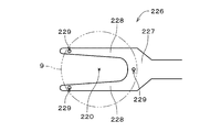
- FIG. 3 is an enlarged plan view showing the vicinity of the hand 226 of the transfer arm 221a.
- the hand 226 of the transfer arm 221b also has a structure similar to that shown in FIG.
- the hand 226 includes, for example, a base portion 227 that expands in the width direction, and two claw portions 228 that extend from both widthwise end portions of the base portion substantially in parallel to the longitudinal direction perpendicular to the width direction.
- a plurality of (for example, three) suction ports 229 are provided on the upper surface of the hand 226. In the example shown in FIG. 3, one suction port 229 is provided at the tip of each claw 228, and one suction port 229 is provided at the center of the base 227 in the width direction. Each suction port 229 is connected to a suction mechanism (not shown).
- Each of the transfer arms 221a and 221b sucks and holds the lower surface of one substrate 9 by the hand 226.
- the position indicated by X in FIG. 3 is the hand center position 220 which is the center position of the hand 226.
- the hand center position 220 is an imaginary point located between the two claws 228.
- the hand center position 220 is the position where the center of the substrate 9 is located when the substrate 922 is held by the hand 226 at the design position (that is, the position indicated by the chain double-dashed line in FIG. 3).
- the hand center position 220 is located at substantially the same distance from the three suction ports 229 of the hand 226, for example.
- the position of the suction port 229 is changed appropriately. Good.
- the transfer arms 221a and 221b move horizontally (that is, in the radial direction around the rotation axis of the arm stage 222) by bending and stretching the multi-joint mechanism by a drive mechanism (not shown) incorporated in the arm stage 222. Move independently of each other.
- the hand 226 is provided on the center robot 22 so that it can move back and forth, move up and down, and rotate freely.
- the center robot 22 causes the transfer arms 221a and 221b holding the substrate 9 by the hand 226 to individually access the mounting unit 40 and the plurality of processing units 21, respectively, so that the mounting unit 40 and the processing unit 21 are connected to each other.
- the center robot 22 and the indexer robot 12 are also referred to as “first transfer robot” and “second transfer robot”, respectively.
- the moving mechanism in the center robot 22 is not limited to the above example, and may be another mechanism.
- a belt feeding mechanism using a pulley and a timing belt may be adopted as a mechanism for moving the transport arms 221a and 221b in the vertical direction.
- each processing unit 21 the processing on the substrate 9 is performed.
- the processing block 20 is provided with twelve processing units 21. Specifically, four processing unit 21 groups stacked in the Z direction are arranged around the processing unit 21 in plan view.
- a partition wall 30 is provided between the indexer block 10 and the processing block 20 for shutting off the atmosphere and extending in the Y direction.
- a part of the partition wall 30 projects toward the processing block 20 side (that is, the (+ X) side).
- this protruding portion is referred to as the “connecting portion 31”.
- the substantially tunnel-shaped internal space 310 of the connecting portion 31 connects the internal space 100 of the indexer block 10 and the internal space 230 of the transport path 23 of the processing block 20.
- the placement unit 40 is placed in the internal space 310 of the communication section 31.
- the mounting unit 40 is provided at the connecting portion between the indexer block 10 and the processing block 20.
- the indexer robot 12 and the center robot 22 can access the mounting unit 40.
- the mounting unit 40 is connected to the plurality of processing units 21 via the transport path 23 in which the center robot 22 is arranged.
- the indexer robot 12 places the unprocessed substrate 9 carried out from the carrier 95 on the placement unit 40.
- the center robot 22 carries out the unprocessed substrate 9 from the mounting unit 40 and carries it into the processing unit 21. Further, the central robot 22 places the processed substrate 9 carried out from the processing unit 21 on the mounting unit 40.
- the indexer robot 12 carries out the processed substrate 9 from the mounting unit 40 and carries it into the carrier 95. In other words, the mounting unit 40 holds the unprocessed substrate 9 transferred from the indexer robot 12 to the center robot 22, and the processed substrate 9 transferred from the center robot 22 to the indexer robot 12.
- the mounting unit 40 includes a first mounting portion 41 and a second mounting portion 42.
- One substrate 9 can be placed on each of the first placing section 41 and the second placing section 42.
- the mounting unit 40 includes two first mounting portions 41 and two second mounting portions 42.
- the two first mounting portions 41 are stacked in the Z direction.
- the two second mounting portions 42 are stacked in the Z direction and are arranged above the two first mounting portions 41.
- the unprocessed substrate 9 is mounted on each first mounting part 41, and the processed substrate 9 is mounted on each second mounting part 42. Note that the numbers and arrangements of the first mounting portion 41 and the second mounting portion 42 may be changed as appropriate.
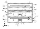
- FIG. 4 is a side view of the mounting unit 40 viewed from the (+ X) side. 4, the housing 410 of each first mounting portion 41 and the housing 420 of each second mounting portion 42 are shown in cross section, and the inside of the mounting unit 40 is illustrated (FIGS. 15 to 15). The same applies to 18).
- each first placement unit 41 includes a housing 410, a substrate support unit 411, a rotation mechanism 412, and a measurement unit 413.
- the housing 410 is a box-shaped member having a substantially rectangular parallelepiped shape.
- the substrate support part 411, the rotation mechanism 412, and the measurement part 413 are housed in the internal space of the housing 410.
- the board supporting unit 411 supports the board 9 in a horizontal state.
- the substrate support portion 411 is, for example, a substantially disc-shaped member having a smaller diameter than the substrate 9.
- the substrate support portion 411 supports the substrate 9 from below by bringing its upper surface into contact with the central portion of the lower surface of the substrate 9.
- a suction port may be provided on the upper surface of the substrate support portion 411 to suck and hold the lower surface of the substrate 9.
- the rotation mechanism 412 rotates the substrate support portion 411 relative to the measurement portion 413 about a rotation axis J1 that faces the up-down direction. In the example shown in FIG. 4, the rotation mechanism 412 rotates the substrate support portion 411 to rotate the substrate 9 supported by the substrate support portion 411.
- the rotation mechanism 412 is, for example, an electric motor connected to the lower surface of the substrate support portion 411.
- the measuring unit 413 measures the edge position, which is the position in the horizontal direction of the peripheral edge of the substrate 9 supported by the substrate supporting unit 411.
- the measurement unit 413 is an optical sensor fixed to the housing 410 near the peripheral edge of the substrate 9.
- the measuring unit 413 includes a light emitting unit 414 and a light receiving unit 415.
- One of the light emitting unit 414 and the light receiving unit 415 is disposed above the substrate 9 and spaced from the substrate 9, and the other is disposed below the substrate 9 and spaced from the substrate 9.
- the light emitting section 414 is arranged above the peripheral edge of the substrate 9, and the light receiving section 415 is arranged below the peripheral edge of the substrate 9.
- the light emitting unit 414 and the light receiving unit 415 are located at substantially the same position in the circumferential direction about the rotation axis J1 (hereinafter, also simply referred to as “circumferential direction”) and overlap each other in a plan view.
- the light emitting unit 414 directs linear light extending substantially parallel to a radial direction (hereinafter, also simply referred to as “radial direction”) about the rotation axis J1 toward the light receiving unit 415 (that is, downward). ) Emit.
- the light emitting unit 414 includes, for example, an LD (Laser Diode) or an LED (Light Emitting Diode) as a light source.
- the light receiving unit 415 is a line sensor that extends over the peripheral edge of the substrate 9 and is substantially parallel to the radial direction.
- the radial length of the light receiving section 415 is, for example, 10 mm to 40 mm.
- the linear light emitted from the light emitting unit 414 straddles the peripheral edge of the substrate 9, and a portion of the linear light radially outside the peripheral edge of the substrate 9 is received by the light receiving unit 415. . Accordingly, the edge position of the substrate 9 (that is, the position of the peripheral edge of the substrate 9 in the radial direction) between the light emitting unit 414 and the light receiving unit 415 (hereinafter, also referred to as “measurement position”) is measured.
- the measurement result of the light receiving unit 415 is sent to the control unit 60, and the control unit 60 obtains the edge position of the substrate 9.
- the edge position of the substrate 9 is continuously measured by the measuring unit 413 while the substrate 9 is being rotated by the rotating mechanism 412. Thereby, the edge position of the substrate 9 is measured over the entire circumference in the circumferential direction.
- Each second mounting part 42 includes a housing 420 and a substrate support part 421.
- the housing 420 is a box-shaped member having a substantially rectangular parallelepiped shape.
- the substrate support portion 421 is housed in the internal space of the housing 420.
- the substrate support portion 421 supports the substrate 9 in a horizontal state.
- the substrate support portion 421 is, for example, a substantially columnar member having a smaller diameter than the substrate 9.
- the substrate support portion 421 supports the substrate 9 from below by bringing its upper surface into contact with the central portion of the lower surface of the substrate 9.
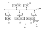
- FIG. 5 is a diagram showing a configuration of the computer 8 included in the control unit 60.
- the computer 8 is a normal computer including a processor 81, a memory 82, an input / output unit 83, and a bus 84.
- the bus 84 is a signal circuit that connects the processor 81, the memory 82, and the input / output unit 83.
- the memory 82 stores programs and various information.
- the processor 81 executes various processes (for example, numerical calculation) while using the memory 82 or the like according to a program or the like stored in the memory 82.
- the input / output unit 83 includes a keyboard 85 and a mouse 86 that receive an input from an operator, a display 87 that displays the output and the like from the processor 81, and a transmission unit 88 that transmits the output and the like from the processor 81.
- FIG. 6 is a block diagram showing functions realized by the computer 8 of the control unit 60.
- the control unit 60 includes a storage unit 61, a calculation unit 62, a transfer robot control unit 63, a notification unit 64, and a rotation mechanism control unit 65.
- the storage unit 61 is mainly realized by the memory 82 and stores various information such as a measurement value by the measurement unit 413 of the mounting unit 40. In addition, the storage unit 61 stores the position of the rotation axis J1 of each first mounting unit 41.
- the calculation unit 62 is realized mainly by the processor 81, and based on the measurement value (for example, the output from each light receiving element of the line sensor described above) stored in the storage unit 61 by the measurement unit 413, the edge position of the substrate 9 is calculated. Is obtained over the entire circumference.
- the calculation unit 62 also obtains the center position of the substrate 9 by a known method based on the edge position of the substrate 9.
- the calculation unit 62 has a radial distance (hereinafter, also referred to as “eccentricity amount”) between the rotation axis J1 of the first mounting unit 41 and the center of the substrate 9 and a circumferential direction of the center of the substrate 9. The position (hereinafter, also referred to as “eccentric direction”) is also obtained.
- the calculation unit 62 determines the relative position of the center of the substrate 9 with respect to the rotation axis J1.
- the computing unit 62 may also determine the position (hereinafter, also referred to as “notch direction”) in the circumferential direction of a notch (not shown) (not shown) provided in advance on the peripheral edge of the substrate 9.
- the transfer robot control unit 63 is mainly realized by the processor 81 and the transmission unit 88, and sends a control signal to the center robot 22 based on the calculation result by the calculation unit 62 and controls the center robot 22.
- the notification unit 64 is mainly realized by the processor 81 and the display 87, and notifies the operator or the like of the substrate processing apparatus 1 of various information such as the calculation result of the calculation unit 62 or a warning based on the calculation result.
- the rotation mechanism control unit 65 is mainly realized by the processor 81 and the transmission unit 88, and sends a control signal to the rotation mechanism 412 of the mounting unit 40 based on the calculation result by the calculation unit 62 and controls the rotation mechanism 412. .
- FIG. 7 is a diagram showing an example of the processing unit 21.
- the processing unit 21 includes a housing 211 and a processing unit 24.
- the processing unit 24 is housed in the internal space of the housing 211.
- the processing unit 24 includes a chuck 241, a substrate rotating mechanism 242, a cup unit 243, a first nozzle 244, a second nozzle 245, and a measuring unit 246.
- the processing unit 24 performs, for example, processing on the peripheral portion of the substrate 9 (that is, bevel processing).
- the chuck 241 is a suction chuck that holds the substrate 9 in a horizontal state.
- the chuck 241 is, for example, a substantially disk-shaped member having a smaller diameter than the substrate 9.
- the upper surface of the chuck 241 contacts the central portion of the lower surface of the substrate 9.
- An adsorption port (not shown) is provided on the upper surface of the chuck 241 to adsorb and hold the lower surface of the substrate 9.
- the substrate rotation mechanism 242 rotates the chuck 241 about a rotation axis J2 that is oriented in the up-down direction, thereby rotating the substrate 9 held by the chuck 241.
- the substrate rotating mechanism 242 is, for example, an electric motor connected to the lower surface of the chuck 241.
- the substrate rotating mechanism 242 is housed inside the cover portion 240 arranged below the chuck 241.
- the cup portion 243 is a substantially cylindrical member that surrounds the entire circumference of the chuck 241.
- the cup portion 243 receives the liquid that is scattered around from the rotating substrate 9.
- the first nozzle 244 supplies the processing liquid toward the peripheral portion of the upper surface of the substrate 9.
- the second nozzle 245 supplies the inert gas toward the center of the upper surface of the substrate 9 and forms a flow of the inert gas radially outward from the center.
- the measuring unit 246 is another measuring unit different from the above-described measuring unit 413, and measures the position of the peripheral edge of the substrate 9 held by the chuck 241 in the horizontal direction (that is, the edge position in the processing unit 21).
- the measuring unit 246 is an optical sensor fixed near the peripheral edge of the substrate 9.
- the measuring unit 246 includes a light emitting unit 247 and a light receiving unit 248, similarly to the measuring unit 413 described above.
- One of the light emitting unit 247 and the light receiving unit 248 is arranged above the substrate 9 so as to be separated from the substrate 9, and the other is arranged below the substrate 9 so as to be separated from the substrate 9.
- the light emitting section 247 is fixed inside the cover section 240 below the peripheral edge of the substrate 9.
- the light receiving portion 248 is fixed to the canopy portion of the housing 211 above the peripheral portion of the substrate 9.
- the light emitting unit 247 and the light receiving unit 248 are located at substantially the same position in the circumferential direction about the rotation axis J2 (hereinafter, also simply referred to as “circumferential direction”) and overlap each other in a plan view.
- the light emitting unit 247 directs linear light extending substantially parallel to a radial direction (hereinafter, also simply referred to as “radial direction”) about the rotation axis J2 toward the light receiving unit 248 (that is, upward). ) Emit.
- the light emitting unit 247 includes, for example, an LD or an LED as a light source.
- the light receiving section 248 is a line sensor that extends over the peripheral edge of the substrate 9 and is substantially parallel to the radial direction.
- the length of the light receiving portion 248 in the radial direction is, for example, 10 mm to 40 mm.
- the linear light emitted from the light emitting unit 247 straddles the peripheral edge of the substrate 9, and the portion of the linear light radially outside the peripheral edge of the substrate 9 is received by the light receiving unit 248. .
- the edge position of the substrate 9 between the light emitting unit 247 and the light receiving unit 248 (that is, the radial position of the peripheral edge of the substrate 9 in the processing unit 21) is measured.
- the measurement result of the light receiving unit 248 is sent to the control unit 60, and the computing unit 62 of the control unit 60 (see FIG. 6) obtains the edge position of the substrate 9 in the processing unit 21.
- the edge position of the substrate 9 is continuously measured by the measuring section 246 while the substrate 9 is being rotated by the substrate rotating mechanism 242. Thereby, the edge position of the substrate 9 in the processing unit 21 is measured over the entire circumference in the circumferential direction.
- the calculation unit 62 calculates the radial distance between the rotation axis J2 of the processing unit 24 and the center of the substrate 9 (that is, the amount of eccentricity in the processing unit 21) and the position of the center of the substrate 9 in the circumferential direction (that is, The eccentric direction in the processing unit 21) is also obtained.
- the position of the notch of the substrate 9 in the circumferential direction (that is, the notch direction in the processing unit 21) may also be obtained.
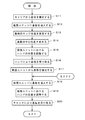
- the substrate processing apparatus 1 first, the substrate 9 is unloaded from the carrier 95 by the indexer robot 12 (step S11). Actually, the two substrates 9 are unloaded from the carrier 95, and the processing described later is performed on the two substrates 9 in parallel. The processing on the substrate 9 will be described.
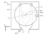
- FIG. 9 is a plan view showing the substrate 9 in the first mounting portion 41.
- reference numeral 93 is attached to the central position of the substrate 9.
- the measurement result by the measurement unit 413 is sent to the control unit 60, and the calculation unit 62 calculates the position of the center 93 of the substrate 9 (that is, the position in the horizontal direction based on the edge position, specifically, the X coordinate). And the Y coordinate) are obtained (step S14). Further, the eccentricity amount of the substrate 9, the eccentric direction, and the notch direction are also calculated by the calculation unit 62.
- the hand 226 of the center robot 22 is moved in the ( ⁇ X) direction and inserted into the first mounting portion 41 of the mounting unit 40, and is positioned below the substrate 9.
- the transfer robot control unit 63 controls the center robot 22 based on the position of the center 93 of the substrate 9 obtained by the calculation unit 62, and as shown in FIG.
- the position of the hand 226 on the first mounting portion 41 of the mounting unit 40 is adjusted so that the center of the substrate 9 and the center 93 of the substrate 9 overlap in the vertical direction (step S15).
- the hand center position 220 is located on the ( ⁇ X) side and the (+ Y) side of the rotation axis J1 of the first mounting portion 41.
- the hand 226 is moved upward, and the lower surface of the substrate 9 is adsorbed and held to receive the substrate 9 from the substrate support portion 411 of the first placing portion 41 (step S16).
- the hand 226 is moved in the (+ X) direction and retracts from the first mounting portion 41, so that the substrate 9 is unloaded from the mounting unit 40 (step S17).
- the hand 226 is inserted into the one processing unit 21, whereby the substrate 9 is carried into the processing unit 21, and is positioned above the chuck 241 of the processing unit 24 (step S18).
- the transfer robot control unit 63 controls the center robot 22 to move the hand in the processing unit 21 so that the hand center position 220 is located on the rotation axis J2 of the processing unit 24, as shown in FIG.
- the position of 226 is adjusted (step S19). As described above, the position of the center 93 of the substrate 9 held by the hand 226 vertically overlaps with the hand center position 220. Therefore, the center 93 of the substrate 9 is adjusted by the position adjustment of the hand 226. It is located on the axis of rotation J2 of 24.
- the chuck 241 receives the substrate 9 from the hand 226, sucks and holds the substrate 9 (step S20).
- the hand 226 retracts from the processing unit 21.
- the rotation of the chuck 241 and the substrate 9 is started by the substrate rotating mechanism 242 shown in FIG.
- the edge position of the substrate 9 in the processing unit 21 is measured by the measuring unit 246 over the entire circumference of the substrate 9 (step S21).
- the measurement result by the measurement unit 246 is sent to the control unit 60, and the arithmetic unit 62 obtains the position of the center 93 of the substrate 9 in the processing unit 21 based on the edge position in the processing unit 21 (step S22).
- the eccentric amount of the substrate 9 in the processing unit 21, the eccentric direction, and the notch direction are also calculated by the calculation unit 62.
- the center 93 of the substrate 9 is located on the rotation axis J2 by adjusting the position of the hand 226 in the processing unit 21 in step S19.
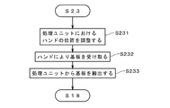
- the control unit 60 confirms that the center 93 of the substrate 9 is located on the rotation axis J2 based on the position of the center 93 of the substrate 9 obtained in step S22 (step S23), the processing unit 24 The substrate 9 is processed according to (step S24).
- a chemical solution for example, an etching solution
- a chemical solution for example, an etching solution
- the flow of the inert gas formed on the substrate 9 by the second nozzle 245 prevents the chemical solution or the like from adhering to the region other than the peripheral portion on the upper surface of the substrate 9.
- a rinse liquid for example, pure water
- the above-described airflow formation by the second nozzle 245 is continued during the rinse process. This prevents the rinse liquid or the like from adhering to the area other than the peripheral portion on the upper surface of the substrate 9. Then, the rotation speed of the substrate 9 is increased and the substrate 9 is dried.
- the processing of the substrate 9 by the processing unit 21 is performed. Is once discontinued.
- the notification unit 64 may notify the operator of the processing termination of the substrate 9. The notification is given by, for example, a display on the display 87 or a warning sound.
- the transfer robot control unit 63 controls the center robot 22, the hand 226 is inserted into the processing unit 21, and is located below the substrate 9. At this time, the transfer robot control unit 63 controls the center robot 22 based on the position of the center 93 of the substrate 9 in the processing unit 21 obtained by the calculation unit 62, and the hand center position 220 and the center 93 of the substrate 9 are separated from each other. The position of the hand 226 in the processing unit 21 is adjusted so as to overlap in the vertical direction (step S231).
- the hand 226 is moved upward, and the lower surface of the substrate 9 is adsorbed and held to receive the substrate 9 from the chuck 241 of the processing unit 24 (step S232).
- the hand 226 retracts from the processing unit 21, and the substrate 9 is unloaded from the processing unit 21 (step S233).
- step S18 the loading of the substrate 9 into the processing unit 21 and the position adjustment of the hand 226 in the processing unit 21 are performed again, and the hand center position 220 and the center 93 of the substrate 9 rotate the processing unit 24. It is located on the axis J2 (steps S18 to S19). Then, the substrate 9 is held by the chuck 241, the edge position of the substrate 9 in the processing unit 21 is measured, and the position of the center 93 of the substrate 9 in the processing unit 21 is calculated (steps S20 to S22). When it is confirmed that the center 93 is located on the rotation axis J1, the processing section 24 processes the substrate 9 (steps S23 to S24).
- the substrate 9 is unloaded from the processing unit 21 by the central robot 22 (step S25), is loaded into the second loading portion 42 of the loading unit 40, and is loaded by the substrate support portion 421. It is supported (step S26). After that, the substrate 9 is unloaded from the second placement section 42 by the indexer robot 12 (step S27), is loaded into the carrier 95, and a series of processing of the substrate 9 is completed (step S28).
- the substrate processing apparatus 1 includes the mounting unit 40, the processing unit 21, the center robot 22, and the control unit 60.
- the substrate 9 is mounted on the mounting unit 40.
- the processing unit 21 processes the substrate 9.
- the center robot 22 is a transfer robot that transfers the substrate 9 from the mounting unit 40 to the processing unit 21.
- the mounting unit 40 includes a substrate supporting unit 411 and a measuring unit 413.
- the substrate support portion 411 supports the substrate 9 in a horizontal state.
- the measuring unit 413 measures the edge position, which is the position in the horizontal direction of the peripheral edge of the substrate 9 supported by the substrate supporting unit 411.
- the center robot 22 has a hand 226.
- the hand 226 receives the substrate 9 supported by the substrate support portion 411 of the mounting unit 40 and carries it into the processing unit 21.
- the control unit 60 includes a calculation unit 62 and a transfer robot control unit 63.
- the calculation unit 62 obtains the center position of the substrate 9 based on the edge position measured by the measurement unit 413.
- the transfer robot control unit 63 adjusts the position of the hand 226 in the mounting unit 40 based on the center position of the substrate 9 before the hand 226 receives the substrate 9 from the substrate support unit 411.
- the substrate processing method of processing the substrate 9 by the substrate processing apparatus 1 including the mounting unit 40, the processing unit 21, and the center robot 22 described above is performed based on the edge position measured by the measuring unit 413.
- the method includes a step of obtaining a position and a step of adjusting the position of the hand 226 in the mounting unit 40 based on the center position of the substrate 9 before the hand 226 receives the substrate 9 from the substrate support portion 411. Thereby, as described above, the positional accuracy of the substrate 9 carried into the processing unit 21 can be improved.
- the hand 226 of the center robot 22 preferably adsorbs and holds the lower surface of the substrate 9. As a result, it is possible to prevent the position of the substrate 9 conveyed by the center robot 22 on the hand 226 from being displaced from the position of the substrate 9 immediately after being received by the center robot 22 from the mounting unit 40. As a result, the positional accuracy of the substrate 9 carried into the processing unit 21 can be further improved.
- the mounting unit 40 preferably further includes the rotating mechanism 412 that relatively rotates the substrate supporting unit 411 with respect to the measuring unit 413 about the rotation axis J1 oriented in the vertical direction.
- the measuring unit 413 measure the edge position of the substrate 9 during relative rotation. This makes it easy to measure the edge positions of the substrate 9 at a plurality of positions in the circumferential direction. Moreover, the edge position of the substrate 9 can be easily measured over the entire circumference in the circumferential direction. In this case, the center position of the substrate 9 can be obtained with high accuracy.
- the processing unit 21 preferably includes the chuck 241 and the other measurement unit (that is, the measurement unit 246).
- the chuck 241 holds the substrate 9 in a horizontal state.
- the measuring unit 246 measures the horizontal position of the peripheral edge of the substrate 9 held by the chuck 241. In this manner, by measuring the horizontal position of the peripheral edge of the substrate 9 in the processing unit 21 (that is, the edge position in the processing unit 21), the substrate 9 held on the chuck 241 is displaced from the predetermined position. Can be detected. As a result, it is possible to prevent processing from being performed on the substrate 9 located at a position displaced from the predetermined position by more than the allowable range.
- the shifted substrate 9 is unloaded from the processing unit 21 by the center robot 22, and as shown in steps S18 to S20, the substrate 9 is loaded again into the processing unit 21 and the chuck 241 is loaded.
- the substrate 9 can be arranged at a predetermined position in the processing unit 21 by holding the substrate 9 by the above, and desired processing can be performed on the substrate 9. As a result, the yield in the substrate processing apparatus 1 can be improved.
- the above steps S23 and S231 to S233 may be omitted.
- the time required for processing the substrate 9 in the processing unit 21 can be shortened.
- the structure of the processing unit 21 can be simplified and the processing unit 21 can be downsized.
- the substrate processing apparatus 1 can be downsized.
- the substrate supported by the substrate support portion 411 by the rotation mechanism 412 (see FIG. 4) of the first mounting portion 41 of the mounting unit 40 between the above-described step S14 and step S15. 9 may be rotated and the position of the center 93 of the substrate 9 in the circumferential direction (that is, the eccentric direction) may be changed.
- the center 93 of the substrate 9 may be arranged so as to be aligned with the rotation axis J1 in the X direction on the (+ X) side of the rotation axis J1.
- center 93 of the substrate 9 may be arranged so as to be aligned with the rotation axis J1 in the X direction on the ( ⁇ X) side of the rotation axis J1.
- the center 93 of the substrate 9 may be arranged so as to be aligned with the rotation axis J1 in the Y direction on the (+ Y) side or the ( ⁇ Y) side of the rotation axis J1.
- the center position of the substrate 9 is moved forward and backward with respect to the rotation axis J1 (that is, the X direction). Or, it is preferable to position in the direction perpendicular to the advancing / retreating direction (that is, the Y direction). Thereby, the position adjustment of the hand 226 in the mounting unit 40 can be facilitated.
- the substrate 9 is rotated so that the center position of the substrate 9 is located closest to the center robot 22 (that is, the substrate 9 is closest to the (+ X) side). It is also preferable to position). As a result, the movement distance of the hand 226 that receives the substrate 9 becomes the shortest, and the time required for processing the substrate 9 can be shortened.
- FIG. 12 is a diagram showing an example of another processing unit 21a.
- the processing unit 21a includes a housing 211a and a processing unit 24a.
- the processing unit 24a is housed in the internal space of the housing 211a.
- the processing unit 24a includes a chuck 241a, a substrate rotating mechanism 242a, a cup unit 243a, a first nozzle 244a, a second nozzle 245a, a measuring unit 246a, and a shielding plate 249a.
- the processing unit 24a performs processing on the lower surface of the substrate 9, for example.
- the chuck 241a is a mechanical chuck that holds the substrate 9 in a horizontal state.
- the chuck 241a includes a base portion 251a and a plurality (for example, four) of chuck pins 252a.
- the base portion 251a is a substantially disk-shaped member having a diameter larger than that of the substrate 9.
- the plurality of chuck pins 252a are arranged in the peripheral direction of the upper surface of the base portion 251a in the circumferential direction at substantially equal angular intervals. The plurality of chuck pins 252a contact the peripheral edge of the substrate 9 to position the substrate 9 in the horizontal direction, and hold the substrate 9 at a position spaced upward from the upper surface of the base portion 251a.
- the substrate rotating mechanism 242a rotates the chuck 241a about a rotation axis J3 which is oriented in the vertical direction, thereby rotating the substrate 9 held by the chuck 241a.
- the substrate rotating mechanism 242a is, for example, an electric motor connected to the lower surface of the chuck 241a.
- the substrate rotating mechanism 242a is housed inside the cover portion 240a arranged below the chuck 241a.
- the shield plate 249a is a substantially disc-shaped member that covers the upper side of the substrate 9. The shield plate 249a is detachably engaged with the chuck 241a and is rotatable with the chuck 241a.
- the cup portion 243a is a substantially cylindrical member that surrounds the entire circumference of the chuck 241a.
- the cup portion 243a receives the liquid that is scattered around from the rotating substrate 9.
- the first nozzle 244a supplies the processing liquid toward the central portion of the lower surface of the substrate 9.
- the first nozzle 244a is arranged inside the hollow shaft portion of the substrate rotating mechanism 242a.
- the second nozzle 245a supplies the inert gas toward the central portion of the upper surface of the substrate 9 and forms a flow of the inert gas radially outward from the central portion.
- the measuring unit 246a is another measuring unit different from the above-described measuring unit 413, and measures the position in the horizontal direction of the peripheral edge of the substrate 9 held by the chuck 241a (that is, the edge position in the processing unit 24a).
- the measuring unit 246 a is an optical sensor fixed near the peripheral edge of the substrate 9.
- the measurement unit 246a has a structure similar to that of the measurement unit 246 described above.
- the measuring unit 246a measures the edge position of the substrate 9 between the light emitting unit 247a and the light receiving unit 248a (that is, the radial position of the peripheral edge of the substrate 9 in the processing unit 24a).
- the measurement result of the light receiving unit 248a is sent to the control unit 60, and the calculation unit 62 (see FIG. 6) of the control unit 60 obtains the edge position of the substrate 9 in the processing unit 24a.
- the edge position of the substrate 9 is continuously measured by the measuring unit 246a while the substrate 9 is being rotated by the substrate rotating mechanism 242a.
- the edge position of the substrate 9 in the processing section 24a is measured over the entire circumference in the circumferential direction.
- a portion that passes between the light emitting portion 247a and the light receiving portion 248a is a light transmitting portion formed of a material that transmits light.
- the calculation unit 62 also obtains the eccentricity amount, the eccentric direction, and the notch direction in the processing unit 24a.
- step S24 a chemical solution (for example, an etching solution) is supplied from the first nozzle 244a to the central portion of the lower surface of the substrate 9 that is rotating in the processing unit 21a, and the entire lower surface is processed with the chemical solution.
- the chemical liquid or the like is prevented from adhering to the upper surface of the substrate 9 due to the flow of the inert gas formed on the substrate 9 by the second nozzle 245a.
- a rinse liquid for example, pure water
- a rinse liquid for example, pure water
- the second nozzle 245a is continued during the rinse process. This prevents the rinse liquid or the like from adhering to the upper surface of the substrate 9.
- the rotation speed of the substrate 9 is increased and the substrate 9 is dried.
- the chuck 241a is displaced from the predetermined position.
- the substrate 9 held by can be detected.
- the measurement unit 413a is omitted from the processing unit 21a if the displacement can be corrected by moving the chuck pin 252a or the like. May be.
- the substrate 9 loaded into the above-described substrate processing apparatus 1 may be warped due to the influence of the processing (that is, pretreatment) performed before being loaded into the substrate processing apparatus 1.
- warp that is, curvature
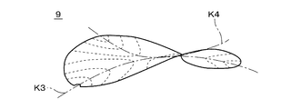
- FIG. 13 and 14 are perspective views showing examples of the substrate 9 having different curved states.
- the substrate 9 shown in FIG. 13 is curved with a first curvature in the first radial direction K1 on one side in the thickness direction (that is, in the upward convex direction in the drawing).
- the substrate 9 In the second radial direction K2 that is orthogonal to the first radial direction K1, the substrate 9 has the first side on the one side in the thickness direction (that is, the same direction as the bending direction in the first radial direction K1). It is curved with a second curvature that is larger than the curvature.
- the substrate 9 shown in FIG. 14 is curved to one side in the thickness direction in the first radial direction K3 (that is, a direction that is convex upward in the drawing).
- the substrate 9 bends in the second radial direction K4 orthogonal to the first radial direction K3 in the other side in the thickness direction (that is, in the direction opposite to the bending direction in the first radial direction K3).
- the degree of curvature of the substrate 9 is a value indicating the degree of curvature of the substrate 9, and the greater the degree of curvature, the more the substrate 9 is curved.
- the curvature of the substrate 9 is, for example, in the thickness direction between the lowermost point and the uppermost point in the thickness direction (that is, the normal direction of the substrate 9) when the curved substrate 9 is in the horizontal posture. It is a value obtained by subtracting the thickness of the flat substrate 9 which is not curved from the distance.
- the actual curvature of the substrate 9 is, for example, 0.5 mm or less.
- FIG. 15 is a diagram showing another example of the mounting unit of the substrate processing apparatus 1.
- FIG. 15 is a side view of the mounting unit 40a viewed from the (+ X) side.
- the mounting unit 40a has the same structure as the mounting unit 40 shown in FIG. 4, except that the measuring unit 413a is provided in the first mounting unit 41 instead of the measuring unit 413 shown in FIG.
- each component of the mounting unit 40a is given the same reference numeral as the corresponding component of the mounting unit 40.
- the measuring unit 413a of the mounting unit 40a in addition to the edge position of the substrate 9, vertically positions the peripheral edge of the substrate 9 supported by the substrate supporting unit 411 (hereinafter, referred to as “edge height”). ".) Is also measured.
- the measurement unit 413a includes a plurality of laser distance sensors 416 and a reflection plate 417.
- the plurality of laser distance sensors 416 are arranged in the radial direction above the peripheral portion of the substrate 9 and fixed to the housing 410.
- the reflector 417 extends in the radial direction below the peripheral edge of the substrate 9.
- the plurality of laser distance sensors 416 and the reflection plate 417 are located at substantially the same position in the circumferential direction and overlap each other in a plan view.
- Each laser distance sensor 416 includes a light emitting element and a light receiving element.
- the laser light emitted downward from the light emitting element is reflected by the substrate 9 or the reflecting plate 417 and is received by the light receiving element. Then, based on the light receiving position in the light receiving element, the vertical distance to the object (that is, the substrate 9 or the reflection plate 417) irradiated with the laser light is obtained.
- the vertical distance (hereinafter, referred to as “measurement distance”) to the object measured by each laser distance sensor 416 is sent to the calculation unit 62 (see FIG. 6) of the control unit 60.
- the calculation unit 62 when the measurement distance measured by the laser distance sensor 416 is larger than a predetermined distance (for example, a distance slightly smaller than the vertical distance between the laser distance sensor 416 and the reflector 417), the laser It is determined that the substrate 9 does not exist below the distance sensor 416. On the other hand, when the measured distance is less than or equal to the predetermined distance, it is determined that the substrate 9 exists below the laser distance sensor 416.
- the computing unit 62 obtains the edge position which is the position in the horizontal direction of the peripheral edge of the substrate 9.
- the measured distance is stored in the storage unit 61 as the position of the upper surface of the substrate 9 in the vertical direction.
- the edge position of the substrate 9 and the vertical position of the upper surface of the substrate 9 are continuously measured by the measuring unit 413a while the substrate 9 is being rotated by the rotation mechanism 412. It Thereby, the edge position of the substrate 9 is measured over the entire circumference in the circumferential direction. Then, the calculation unit 62 obtains the center position of the substrate 9, the eccentric amount, the eccentric direction, and the notch direction (step S14).
- the vertical position of the upper surface of the peripheral portion of the substrate 9 is also measured by the measuring portion 413a over the entire circumference in the circumferential direction.
- the edge height which is the vertical position of the peripheral edge of the substrate 9 is obtained over the entire circumference of the substrate 9 by the calculation unit 62 based on the measurement result, and based on the edge height.
- the shape of the peripheral edge of the substrate 9 is required.
- the computing unit 62 obtains the degree of curvature of the substrate 9 based on the edge height of the substrate 9 measured by the measuring unit 413a.
- the control unit 60 causes the substrate 9 to be excessively curved and normally processes the substrate 9 by the processing units 21 and 21a. Determine that you cannot.
- the notification unit 64 notifies the operator of the bending degree abnormality (that is, the bending of the substrate 9 exceeds the allowable range and is large).
- the notification is given by, for example, a display on the display 87 or a warning sound.
- the substrate 9 determined to have the abnormal curvature is discharged from the substrate processing apparatus 1 without being processed by the processing units 21 and 21a, for example. It should be noted that the notification of the curvature abnormality to the operator may be omitted.
- the hand 226 of the center robot 22 is inserted into the first mounting portion 41 of the mounting unit 40a, and the hand center position 220 and the substrate 9 are positioned.
- the position of the hand 226 on the first mounting portion 41 is adjusted so that the center 93 of the hand overlaps the vertical direction (step S15).
- the rotation mechanism 412 of the first mounting unit 41 is driven by the rotation mechanism control unit 65 (see FIG. 6) and is supported by the substrate supporting unit 411 between Step S14 and Step S15 described above.
- the substrate 9 being rotated may be rotated and the orientation of the substrate 9 may be changed to an orientation suitable for holding by the hand 226.
- the rotation mechanism control unit 65 controls the rotation mechanism 412 based on the shape of the peripheral edge of the substrate 9 obtained by the calculation unit 62 in step S14.
- the first radial direction K1 having a relatively small curvature is parallel to the longitudinal direction of the hand 226 (that is, the direction in which the claw portion 228 of the hand 226 extends). Further, the orientation of the substrate 9 is adjusted by the rotation mechanism 412. As a result, the contact area between the two claw portions 228 and the lower surface of the substrate 9 increases, and the substrate 9 is stably held by the hand 226.
- the rotation mechanism 412 of the first mounting section 41 is driven by the rotation mechanism control section 65 and is supported by the substrate support section 411. 9 may be rotated and the orientation of the substrate 9 may be changed to an orientation suitable for holding by the chuck 241a of the processing unit 21a (see FIG. 12).
- the rotation mechanism control unit 65 controls the rotation mechanism 412 based on the shape of the peripheral edge of the substrate 9 obtained by the calculation unit 62 in step S14.
- the chuck 241a of the processing unit 21a includes the four chuck pins 252a arranged at 90 ° intervals as described above.
- the substrate 9 shown in FIG. 14 there are four points where two radial directions inclined by 45 ° with respect to the first radial direction K3 and the second radial direction K4 and the peripheral edge of the substrate 9 intersect. , Located at approximately the same position in the vertical direction. Therefore, when the substrate 9 is passed from the hand 226 to the chuck 241a, the substrate 9 is held by the hand 226 so that the four points on the peripheral edge of the substrate 9 come into contact with the above-described four chuck pins 252a. Is preferred. As a result, all the chuck pins 252a of the chuck 241a come into contact with the peripheral edge of the substrate 9, so that the substrate 9 is stably held by the chuck 241a.
- the rotation mechanism is arranged such that the first radial direction K3 or the second radial direction K4 is parallel to the longitudinal direction of the hand 226 (that is, the direction in which the claw portion 228 of the hand 226 extends).
- the orientation of the substrate 9 is adjusted by 412.
- the measuring unit 413a also measure the edge height that is the vertical position of the peripheral edge of the substrate 9 supported by the substrate supporting unit 411. Further, it is preferable that the computing unit 62 also obtains the shape of the peripheral edge of the substrate 9 based on the edge height measured by the measuring unit 413a. Accordingly, when the substrate 9 is curved, the shape of the peripheral edge of the substrate 9 (that is, the curved state of the substrate 9) can be acquired without significantly changing the structures of the mounting unit and the substrate processing apparatus 1. it can.
- the computing unit 62 also obtains the degree of curvature indicating the degree of bending of the substrate 9 based on the edge height measured by the measuring unit 413a. Further, it is preferable that the control unit 60 further includes a notification unit 64 that notifies the abnormality of the bending degree when the bending degree of the substrate 9 obtained by the calculation unit 62 is larger than a predetermined threshold value. As a result, the substrate 9 having the abnormal curvature can be found early. Further, by paying out the substrate 9 from the substrate processing apparatus 1, useless substrate processing can be prevented.
- the control unit 60 further includes the rotation mechanism control unit 65 that controls the rotation mechanism 412.
- the rotation mechanism control unit 65 drives the rotation mechanism 412 to rotate the substrate 9 based on the shape of the peripheral edge of the substrate 9 obtained by the calculation unit 62, and orients the substrate 9 in a direction suitable for holding by the hand 226. . Thereby, even when the substrate 9 is curved, the substrate 9 can be stably held by the hand 226.
- the control unit 60 further includes a rotation mechanism control unit 65 that controls the rotation mechanism 412.
- the processing unit 21a includes a mechanical chuck (that is, a chuck 241a) that contacts the peripheral edge of the substrate 9 and holds the substrate 9 in a horizontal state.
- the rotation mechanism control unit 65 drives the rotation mechanism 412 to rotate the substrate 9 based on the shape of the peripheral edge of the substrate 9 obtained by the calculation unit 62, and moves the substrate 9 in a direction suitable for holding by the mechanical chuck. Turn. Accordingly, even when the substrate 9 is curved, the substrate 9 can be stably held by the mechanical chuck.
- the mounting units 40 and 40a may have various structures.
- the measuring unit 413 shown in FIG. 4 may be provided in addition to the measuring unit 413a.
- the measuring unit 413a including the laser distance sensor 416 determines the edge height of the substrate 9, and the measuring unit 413, which is an optical sensor, determines the edge position of the substrate 9.
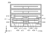
- the internal spaces of the two first mounting portions 41 are vertically connected, and the two substrate support portions 411 are simultaneously rotated by one rotation mechanism 412, so that two measurements are performed.
- the edge positions of the two substrates 9 are measured by the unit 413.
- the structure of the mounting unit 40b can be simplified.
- the lower substrate support portion 411 is directly connected to the rotation mechanism 412, and the upper substrate support portion 411 is indirectly connected to the rotation mechanism 412 via the frame 418b. It is connected to the.
- the frame 418b includes a first member 431, a plurality of first arms 432, a plurality of support members 433, a plurality of second arms 434, and a second member 435.
- the first member 431 is a substantially disk-shaped member fixed to the outer surface of the shaft portion of the rotating mechanism 412.
- the plurality of first arms 432 are substantially rod-shaped members that extend radially outward from the first member 431.
- the second member 435 is a substantially disc-shaped member fixed to the lower end of the upper substrate support portion 411.
- the plurality of second arms 434 are substantially rod-shaped members that extend radially outward from the second member 435.
- Each of the plurality of first arms 432 and the plurality of second arms 435 is, for example, four.
- the plurality of first arms 432 and the plurality of second arms 435 are arranged at substantially equal angular intervals in the circumferential direction and overlap each other in a plan view.
- Each of the plurality of column members 433 is a substantially rod-shaped member that extends in the up-down direction and connects the radially outer ends of the first arms 432 and the radially outer ends of the second arms 435.
- the internal spaces of the two first mounting portions 41 are vertically connected.
- the two upper and lower substrate support portions 411 are fixed to the housing 410 and do not rotate.
- two measurement units 413 are indirectly connected to one rotation mechanism 412 via a frame 418c, and the two measurement units 413 are rotated by the rotation mechanism 412 about the rotation axis J1.
- the rotation mechanism 412 causes the two substrate support portions 411 to rotate relative to the two measurement portions 413. Thereby, the edge positions of the two substrates 9 are measured over the entire circumference.
- the mounting unit 40c includes the rotation mechanism 412 that rotates the substrate supporting unit 411 relative to the measuring unit 413 about the rotation axis J1 that faces the up-down direction.
- the measuring unit 413 also measures the edge position of the substrate 9 during relative rotation. This makes it easy to measure the edge positions of the substrate 9 at a plurality of positions in the circumferential direction. Moreover, the edge position of the substrate 9 can be easily measured over the entire circumference in the circumferential direction. In this case, the center position of the substrate 9 can be obtained with high accuracy.
- the second mounting section 42 may be omitted, and the processed substrate 9 may be mounted on the first mounting section 41.
- the mounting units 40a to 40C The same applies to the mounting units 40a to 40C.
- the measurement of the edge position of the substrate 9 in the mounting unit described above does not necessarily have to be performed over the entire circumference of the substrate 9.
- the rotation mechanism 412 is omitted from the first mounting portion 41, and is fixed to the housing 410 around the substrate 9 supported by the non-rotating substrate supporting portion 411.
- Three or more measurement units 413 may be provided.
- the calculation unit 62 obtains the center position of the substrate 9 by a known method based on the three or more edge positions of the substrate 9 measured by the three or more measuring units 413.
- the structure of the center robot 22 may be changed in various ways.
- the number of substrates 9 that can be transferred at one time by the central robot 22 may be one, or three or more.
- the shape and structure of the hand 226 of the center robot 22 may be variously changed.
- the hand 226 may hold the substrate 9 by a method other than suction.
- the structure of the indexer robot 12 may be changed in various ways.
- the processing block 20 of the substrate processing apparatus 1 may be provided with processing units of various structures other than the processing units 21 and 21a, and various processing may be performed on the substrate 9.
- the chuck that holds the substrate 9 in the processing unit is not limited to the chucks 241 and 241a described above, and chucks having various structures may be provided in the processing unit.
- the substrate processing apparatus 1 described above is used for a glass substrate used for a flat panel display (Flat Panel Display) such as a liquid crystal display device or an organic EL (Electro Luminescence) display device, or another display device, in addition to the semiconductor substrate. It may be used for the processing of the glass substrate.
- the substrate processing apparatus 1 described above may be used for processing optical disk substrates, magnetic disk substrates, magneto-optical disk substrates, photomask substrates, ceramic substrates, solar cell substrates, and the like.
- Substrate Processing Device 9 Substrate 21, 21a Processing Unit 22 Center Robot 40, 40a-40d Placement Unit 60 Control Unit 62 Calculation Unit 63 Transfer Robot Control Unit 64 Notification Unit 65 Rotation Mechanism Control Unit 93 (Substrate) Center 226 Hand 241 , 241a Chuck 246, 246a (Processing unit) measuring unit 411 Substrate supporting unit 412 Rotation mechanism 413, 413a (Mounting unit) measuring unit J1 Rotation axis S11 to S28, S231 to S233 Steps
Landscapes
- Container, Conveyance, Adherence, Positioning, Of Wafer (AREA)
- Cleaning Or Drying Semiconductors (AREA)
- Weting (AREA)
Abstract
基板処理装置の載置ユニット(40)は、基板支持部(411)と、測定部(413)とを備える。基板支持部(411)は、基板(9)を水平状態で支持する。測定部(413)は、基板支持部(411)に支持された基板(9)の周縁の水平方向における位置であるエッジ位置を測定する。センターロボットは、載置ユニット(40)の基板支持部(411)に支持された基板(9)を受け取り、処理ユニットへと搬入する。制御部の演算部は、測定部(413)により測定されたエッジ位置に基づいて基板(9)の中心位置を求める。搬送ロボット制御部は、センターロボットのハンドが基板支持部(411)から基板(9)を受け取る前に、基板(9)の中心位置に基づいて、載置ユニット(40)におけるハンドの位置を調整する。これにより、処理ユニットに搬入される基板(9)の位置精度を向上することができる。
Description
本発明は、基板を処理する基板処理装置および基板処理方法に関する。
従来、基板を処理する基板処理装置では、フープ等に収容されている基板が、インデクサロボットにより搬出され、センターロボットに渡された後、処理室に搬入されて様々な処理を施される。当該基板処理装置では、基板に対する処理が行われる前に、基板の位置決めが行われる。
例えば、特開2003-152055号公報(文献1)のウエハ処理システムでは、ウエハの位置決めを行うウエハ位置決め装置が、ウエハを搬送するウエハ搬送装置、および、ウエハのエッチング処理を行うウエハ処理装置とは別に設けられている。当該ウエハ位置決め装置では、スピンドルにより回転するウエハの周縁部の位置がラインセンサにより測定されてウエハの偏心量が求められ、当該偏心量に応じた距離だけスピンドルが移動された後、ウエハ搬送装置のフィンガーにより基板が取り出される。特開2008-53552号公報(文献2)の基板処理装置においても同様に、基板の位置決めを行うアライメントユニットが、多関節搬送アームが設けられた搬送室、および、基板の処理を行うプロセスユニットとは別に設けられている。
一方、特許第5449239号公報(文献3)の基板処理装置では、基板の処理を行う複数の処理ユニット内に、基板に対してベベル処理を行う基板処理装置と、位置決めを行う基板位置決め装置とが組み込まれている。当該基板位置決め装置は、基板が載置された回転部を挟んで径方向に対向する2つの位置決め機構部を備える。各位置決め機構部は、基板の側面と接触する樹脂製の接触部を備え、当該接触部により基板を側面から押して径方向に直線的に移動させることにより、基板の位置決めを機械的に行う。
ところで、文献1および文献2の装置では、基板の位置決めを行うユニットが、他のユニットとは別に設けられているため、装置が大型化するおそれがある。また、文献3の基板処理装置でも、複数の処理ユニットの内部に基板位置決め装置がそれぞれ組み込まれるため、処理ユニットおよび装置が大型化するおそれがある。さらに、文献3の基板処理装置では、基板を径方向に押すための樹脂製の接触部が、基板との接触が繰り返されることにより摩耗し、基板の位置決め精度が低下するおそれもある。
本発明は、基板を処理する基板処理装置に向けられており、基板処理装置において処理ユニットに搬入される基板の位置精度を向上することを目的としている。
本発明の好ましい一の形態に係る基板処理装置は、基板が載置される載置ユニットと、前記基板を処理する処理ユニットと、前記載置ユニットから前記処理ユニットへと前記基板を搬送する搬送ロボットと、制御部とを備える。前記載置ユニットは、前記基板を水平状態で支持する基板支持部と、前記基板支持部に支持された前記基板の周縁の水平方向における位置であるエッジ位置を測定する測定部とを備える。前記搬送ロボットは、前記載置ユニットの前記基板支持部に支持された前記基板を受け取り、前記処理ユニットへと搬入するハンドを備える。前記制御部は、前記測定部により測定された前記エッジ位置に基づいて前記基板の中心位置を求める演算部と、前記ハンドが前記基板支持部から前記基板を受け取る前に、前記基板の前記中心位置に基づいて前記載置ユニットにおける前記ハンドの位置を調整する搬送ロボット制御部とを備える。これにより、処理ユニットに搬入される基板の位置精度を向上することができる。
好ましくは、前記ハンドは、前記基板の下面を吸着して保持する。
好ましくは、前記載置ユニットは、上下方向を向く回転軸を中心として前記基板支持部を前記測定部に対して相対的に回転する回転機構をさらに備える。前記測定部は、相対回転中の前記基板の前記エッジ位置を測定する。
好ましくは、前記載置ユニットは、上下方向を向く回転軸を中心として前記基板支持部を回転する回転機構をさらに備える。前記ハンドが前記基板支持部から前記基板を受け取る前に、前記回転機構により前記基板を回転させて、前記基板の前記中心位置を、前記回転軸に対して、前記ハンドの前記基板に対する進退方向、または、前記進退方向に垂直な方向に位置させる。
好ましくは、前記処理ユニットは、前記基板を水平状態で保持するチャックと、前記チャックに保持された前記基板の前記周縁の水平方向における位置を測定する他の測定部とを備える。
好ましくは、前記測定部は、前記基板支持部に支持された前記基板の前記周縁の上下方向の位置であるエッジ高さも測定する。前記演算部は、前記測定部により測定された前記エッジ高さに基づいて前記基板の前記周縁の形状も求める。
好ましくは、前記演算部は、前記測定部により測定された前記エッジ高さに基づいて前記基板の湾曲の程度を示す湾曲度も求める。前記制御部は、前記演算部により求められた前記基板の前記湾曲度が所定の閾値よりも大きい場合に湾曲度異常を報知する報知部をさらに備える。
好ましくは、前記載置ユニットは、上下方向を向く回転軸を中心として前記基板支持部を回転する回転機構をさらに備える。前記制御部は、前記演算部により求められた前記基板の前記周縁の形状に基づいて、前記回転機構を駆動して前記基板を回転させ、前記ハンドによる保持に適した向きに前記基板を向ける回転機構制御部をさらに備える。
好ましくは、前記処理ユニットは、前記基板の前記周縁に接触して前記基板を水平状態で保持するメカニカルチャックを備える。前記載置ユニットは、上下方向を向く回転軸を中心として前記基板支持部を回転する回転機構をさらに備える。前記制御部は、前記演算部により求められた前記基板の前記周縁の形状に基づいて、前記回転機構を駆動して前記基板を回転させ、前記メカニカルチャックによる保持に適した向きに前記基板を向ける回転機構制御部をさらに備える。
本発明は、基板処理装置によって基板を処理する基板処理方法にも向けられている。前記基板処理装置は、基板が載置される載置ユニットと、前記基板を処理する処理ユニットと、前記載置ユニットから前記処理ユニットへと前記基板を搬送する搬送ロボットとを備える。前記載置ユニットは、前記基板を水平状態で支持する基板支持部と、前記基板支持部に支持された前記基板の周縁の水平方向における位置であるエッジ位置を測定する測定部とを備える。前記搬送ロボットは、前記載置ユニットの前記基板支持部に支持された前記基板を受け取り、前記処理ユニットへと搬入するハンドを備える。前記基板処理方法は、a)前記測定部により測定された前記エッジ位置に基づいて前記基板の中心位置を求める工程と、b)前記ハンドが前記基板支持部から前記基板を受け取る前に、前記基板の前記中心位置に基づいて前記載置ユニットにおける前記ハンドの位置を調整する工程とを備える。これにより、処理ユニットに搬入される基板の位置精度を向上することができる。
上述の目的および他の目的、特徴、態様および利点は、添付した図面を参照して以下に行うこの発明の詳細な説明により明らかにされる。
図1は、本発明の一の実施の形態に係る基板処理装置1の平面図である。図2は、基板処理装置1を、図1のII-II線から見た図である。なお、以下に参照する各図には、Z軸方向を鉛直方向(すなわち、上下方向)とし、XY平面を水平面とするXYZ直交座標系が適宜付されている。なお、図2では、基板処理装置1の(+X)側の一部の図示を省略している。
基板処理装置1は、複数の略円板状の半導体基板9(以下、単に「基板9」という。)に連続して処理を行う装置である。基板処理装置1では、例えば、基板9に対して処理液を供給する液処理が行われる。基板処理装置1は、複数のキャリアステージ11と、インデクサブロック10と、処理ブロック20と、載置ユニット40と、制御部60と、を備える。インデクサブロック10および処理ブロック20はそれぞれ、インデクサセルおよび処理セルとも呼ばれる。また、インデクサブロック10は、Equipment Front End Module(EDEM)ユニット等とも呼ばれる。図1に示す例では、(-X)側から(+X)側に向かって、複数(例えば、3個)のキャリアステージ11、インデクサブロック10および処理ブロック20が、この順に隣接して配置されている。
複数のキャリアステージ11は、インデクサブロック10の(-X)側の側壁に沿ってY方向に配列される。複数のキャリアステージ11はそれぞれ、キャリア95が載置される載置台である。キャリア95は、複数の円板状の基板9を収納可能である。インデクサブロック10の(-X)側の側壁には、各キャリアステージ11上のキャリア95に対応する位置に開口部が設けられる。当該開口部にはキャリア用シャッタが設けられており、キャリア95に対する基板9の搬出入が行われる際には、当該キャリア用シャッタが開閉される。
各キャリアステージ11に対しては、複数の未処理の基板9を収納したキャリア95が、基板処理装置1の外部から、AGV(Automated Guided Vehicle)等により搬入されて載置される。また、処理ブロック20における処理が終了した処理済みの基板9は、キャリアステージ11に載置されたキャリア95に、再度収納される。処理済みの基板9が収納されたキャリア95は、AGV等によって基板処理装置1の外部に搬出される。すなわち、キャリアステージ11は、未処理の基板9および処理済みの基板9を集積する基板集積部として機能する。
キャリア95は、例えば、基板9を密閉空間に収納するFOUP(Front Opening Unified Pod)である。キャリア95は、FOUPには限定されず、例えば、SMIF(Standard Mechanical Inter Face)ポッド、または、収納された基板9を外気に曝すOC(Open Cassette)であってもよい。また、キャリアステージ11の数は、1個であってもよく、2個以上であってもよい。
インデクサブロック10は、キャリア95から未処理の基板9を受け取り、処理ブロック20に渡す。また、インデクサブロック10は、処理ブロック20から搬出された処理済みの基板9を受け取り、キャリア95へと搬入する。インデクサブロック10の内部空間100には、キャリア95への基板9の搬出入を行うインデクサロボット12が配置される。
インデクサロボット12は、2本の搬送アーム121a,121bと、アームステージ122と、可動台123とを備える。2本の搬送アーム121a,121bは、アームステージ122に搭載される。可動台123は、複数のキャリアステージ11の配列方向と平行に(すなわち、Y方向に沿って)延びるボールネジ124に螺合され、2本のガイドレール125に対して摺動自在に設けられる。図示を省略する回転モータによりボールネジ124が回転すると、可動台123を含むインデクサロボット12の全体が、Y方向に沿って水平に移動する。
アームステージ122は、可動台123上に搭載される。可動台123には、アームステージ122を上下方向(すなわち、Z方向)に延びる回転軸周りに回転させるモータ(図示省略)、および、アームステージ122を上下方向に沿って移動させるモータ(図示省略)が内蔵されている。アームステージ122上には、搬送アーム121a,121bが、上下に離間して配置されている。
搬送アーム121a,121bの先端にはそれぞれ、平面視において略U字状のハンド126が設けられる。ハンド126は、例えば、幅方向に広がる基部と、当該基部の幅方向両端部から幅方向に垂直な長手方向に略平行に延びる2本の爪部とを備える。搬送アーム121a,121bはそれぞれ、ハンド126により1枚の基板9の下面を支持する。また、搬送アーム121a,121bは、アームステージ122に内蔵された駆動機構(図示省略)によって多関節機構が屈伸されることにより、水平方向(すなわち、アームステージ122の回転軸を中心とする径方向)に沿って互いに独立して移動する。換言すれば、ハンド126は、進退自在、昇降自在かつ回転自在にインデクサロボット12に設けられる。
インデクサロボット12は、ハンド126により基板9を保持する搬送アーム121a,121bをそれぞれ、キャリアステージ11に載置されたキャリア95、および、載置ユニット40に個別にアクセスさせることにより、キャリア95および載置ユニット40の間で基板9を搬送する搬送ロボットである。インデクサロボット12における上記移動機構は、上述の例には限定されず、他の機構であってもよい。例えば、搬送アーム121a,121bを上下方向に移動する機構として、プーリとタイミングベルトとを使用したベルト送り機構等が採用されてもよい。
処理ブロック20には、基板9の搬送に利用される搬送路23と、搬送路23の周囲に配置される複数の処理ユニット21とが設けられる。図1に示す例では、搬送路23は、処理ブロック20のY方向の中央にてX方向に延びる。搬送路23の内部空間230には、各処理ユニット21への基板9の搬出入を行うセンターロボット22が配置される。
センターロボット22は、2本の搬送アーム221a,221bと、アームステージ222と、基台223とを備える。2本の搬送アーム221a,221bは、アームステージ222に搭載される。基台223は、処理ブロック20のフレームに固定されている。
アームステージ222は、基台223上に搭載される。基台223には、アームステージ222を上下方向に延びる回転軸周りにて回転させるモータ(図示省略)、および、アームステージ222を上下方向に沿って移動させるモータ(図示省略)が内蔵されている。アームステージ222上には、搬送アーム221a,221bが、上下に離間して配置されている。
搬送アーム221a,221bの先端にはそれぞれ、平面視において略U字状のハンド226が設けられる。図3は、搬送アーム221aのハンド226近傍を拡大して示す平面図である。搬送アーム221bのハンド226についても、図3に示すものと同様の構造を有する。ハンド226は、例えば、幅方向に広がる基部227と、当該基部の幅方向両端部から幅方向に垂直な長手方向に略平行に延びる2本の爪部228とを備える。ハンド226の上面には、複数(例えば、3つ)の吸着口229が設けられる。図3に示す例では、各爪部228の先端部に1つの吸着口229が設けられ、基部227の幅方向の中央部に1つの吸着口229が設けられる。各吸着口229は、図示省略の吸引機構に接続される。
搬送アーム221a,221bはそれぞれ、ハンド226により1枚の基板9の下面を吸着して保持する。図3中に×印にて示す位置は、ハンド226の中心位置であるハンド中心位置220である。ハンド中心位置220は、2つの爪部228の間に位置する仮想点である。ハンド中心位置220は、ハンド226により基板9が設計位置(すなわち、図3中に二点鎖線にて示す位置)にて保持された場合に、基板9の中心が位置する位置である。ハンド中心位置220は、例えば、ハンド226の3つの吸着口229から略同じ距離に位置する。なお、ハンド226により基板9が保持された状態において、ハンド中心位置220と基板9の中心位置とが平面視にて略同じ位置に位置するのであれば、吸着口229の位置は適宜変更されてよい。
搬送アーム221a,221bは、アームステージ222に内蔵された駆動機構(図示省略)によって多関節機構が屈伸されることにより、水平方向(すなわち、アームステージ222の回転軸を中心とする径方向)に沿って互いに独立して移動する。換言すれば、ハンド226は、進退自在、昇降自在かつ回転自在にセンターロボット22に設けられる。
センターロボット22は、ハンド226により基板9を保持する搬送アーム221a,221bをそれぞれ、載置ユニット40および複数の処理ユニット21に個別にアクセスさせることにより、載置ユニット40および処理ユニット21の間で基板9を搬送する搬送ロボットである。以下の説明では、センターロボット22およびインデクサロボット12をそれぞれ、「第1搬送ロボット」および「第2搬送ロボット」とも呼ぶ。センターロボット22における上記移動機構は、上述の例には限定されず、他の機構であってもよい。例えば、搬送アーム221a,221bを上下方向に移動する機構として、プーリとタイミングベルトとを使用したベルト送り機構等が採用されてもよい。
各処理ユニット21では、基板9に対する処理が行われる。図1および図2に示す例では、処理ブロック20には、12個の処理ユニット21が設けられる。具体的には、Z方向に積層された3個の処理ユニット21群が、平面視における処理ユニット21の周囲に4組配置される。
インデクサブロック10と処理ブロック20との間には、およそY方向に延びる雰囲気遮断用の隔壁30が設けられる。インデクサブロック10のY方向の中央部では、隔壁30の一部が、処理ブロック20側(すなわち、(+X)側)に突出している。以下の説明では、当該突出した部位「連絡部31」と呼ぶ。連絡部31の略トンネル状の内部空間310は、インデクサブロック10の内部空間100と、処理ブロック20の搬送路23の内部空間230とを連絡する。
載置ユニット40は、連絡部31の内部空間310に載置される。換言すれば、載置ユニット40は、インデクサブロック10と処理ブロック20との接続部に設けられる。上述のように、インデクサロボット12およびセンターロボット22は、載置ユニット40にアクセス可能である。載置ユニット40は、センターロボット22が配置される搬送路23を介して複数の処理ユニット21に接続される。
インデクサロボット12は、キャリア95から搬出した未処理の基板9を載置ユニット40に載置する。センターロボット22は、載置ユニット40から未処理の基板9を搬出し、処理ユニット21へと搬入する。また、センターロボット22は、処理ユニット21から搬出した処理済みの基板9を載置ユニット40に載置する。インデクサロボット12は、載置ユニット40から処理済みの基板9を搬出し、キャリア95に搬入する。換言すれば、載置ユニット40は、インデクサロボット12からセンターロボット22へと渡される未処理の基板9、および、センターロボット22からインデクサロボット12へと渡される処理済みの基板9を保持する。
載置ユニット40は、第1載置部41と、第2載置部42とを備える。第1載置部41および第2載置部42には、それぞれ1枚の基板9が載置可能である。図2に示す例では、載置ユニット40は、2つの第1載置部41と、2つの第2載置部42とを備える。2つの第1載置部41はZ方向に積層される。2つの第2載置部42は、Z方向に積層され、2つの第1載置部41の上側に配置される。本実施の形態では、各第1載置部41には、未処理の基板9が載置され、各第2載置部42には、処理済みの基板9が載置される。なお、第1載置部41および第2載置部42の数および配置は、適宜変更されてよい。
図4は、載置ユニット40を(+X)側から見た側面図である。図4では、各第1載置部41の筐体410、および、各第2載置部42の筐体420を断面にて示し、載置ユニット40の内部を図示している(図15~18においても同様)。図4に示す例では、各第1載置部41は、筐体410と、基板支持部411と、回転機構412と、測定部413とを備える。筐体410は、略直方体状の箱形部材である。基板支持部411、回転機構412および測定部413は、筐体410の内部空間に収容される。
基板支持部411は、基板9を水平状態で支持する。基板支持部411は、例えば、基板9よりも直径が小さい略円板状の部材である。基板支持部411は、その上面を基板9の下面の中央部に接触させて基板9を下方から支持する。基板支持部411の上面に吸着口が設けられ、基板9の下面を吸着して保持してもよい。回転機構412は、上下方向を向く回転軸J1を中心として、基板支持部411を測定部413に対して相対的に回転する。図4に示す例では、回転機構412が基板支持部411を回転することにより、基板支持部411に支持された基板9を回転する。回転機構412は、例えば、基板支持部411の下面に接続される電動モータである。
測定部413は、基板支持部411に支持された基板9の周縁の水平方向における位置であるエッジ位置を測定する。図4に示す例では、測定部413は、基板9の周縁近傍にて筐体410に固定される光センサである。測定部413は、発光部414と、受光部415とを備える。発光部414および受光部415のうち一方は基板9の上側に基板9から離間して配置され、他方は基板9の下側に基板9から離間して配置される。図4に示す例では、発光部414が基板9の周縁部の上方に配置され、受光部415が基板9の周縁部の下方に配置される。発光部414および受光部415は、回転軸J1を中心とする周方向(以下、単に「周方向」とも呼ぶ。)において略同じ位置に位置し、平面視において重なる。
発光部414は、回転軸J1を中心とする径方向(以下、単に「径方向」とも呼ぶ。)に略平行に延びる直線状の光を、受光部415に向けて(すなわち、下方に向けて)出射する。発光部414は、例えば、LD(Laser Diode)またはLED(Light Emitting Diode)を光源として備える。受光部415は、基板9の周縁を跨いで径方向に略平行に延びるラインセンサである。受光部415の径方向の長さは、例えば10mm~40mmである。発光部414から出射される直線状の光は、基板9の周縁を跨いでおり、当該直線状の光のうち、基板9の周縁よりも径方向外側の部分が、受光部415により受光される。これにより、発光部414と受光部415との間(以下、「測定位置」とも呼ぶ。)における基板9のエッジ位置(すなわち、基板9の周縁の径方向における位置)が測定される。
具体的には、受光部415における測定結果が制御部60へと送られ、制御部60により基板9のエッジ位置が求められる。第1載置部41では、回転機構412により基板9が回転している状態で、測定部413による基板9のエッジ位置の測定が継続的に行われる。これにより、基板9のエッジ位置が、周方向の全周に亘って測定される。
各第2載置部42は、筐体420と、基板支持部421とを備える。筐体420は、略直方体状の箱形部材である。基板支持部421は、筐体420の内部空間に収容される。基板支持部421は、基板9を水平状態で支持する。基板支持部421は、例えば、基板9よりも直径が小さい略円柱状の部材である。基板支持部421は、その上面を基板9の下面の中央部に接触させて基板9を下方から支持する。
図5は、制御部60が備えるコンピュータ8の構成を示す図である。コンピュータ8は、プロセッサ81と、メモリ82と、入出力部83と、バス84とを備える通常のコンピュータである。バス84は、プロセッサ81、メモリ82および入出力部83を接続する信号回路である。メモリ82は、プログラムおよび各種情報を記憶する。プロセッサ81は、メモリ82に記憶されるプログラム等に従って、メモリ82等を利用しつつ様々な処理(例えば、数値計算)を実行する。入出力部83は、操作者からの入力を受け付けるキーボード85およびマウス86、プロセッサ81からの出力等を表示するディスプレイ87、並びに、プロセッサ81からの出力等を送信する送信部88を備える。
図6は、制御部60のコンピュータ8により実現される機能を示すブロック図である。制御部60は、記憶部61と、演算部62と、搬送ロボット制御部63と、報知部64と、回転機構制御部65とを備える。記憶部61は、主にメモリ82により実現され、載置ユニット40の測定部413による測定値等の各種情報を記憶する。また、記憶部61は、各第1載置部41の回転軸J1の位置を記憶している。
演算部62は、主にプロセッサ81により実現され、記憶部61に記憶された測定部413による測定値(例えば、上述のラインセンサの各受光素子からの出力)に基づいて、基板9のエッジ位置を全周に亘って求める。また、演算部62は、基板9のエッジ位置に基づいて、公知の方法で基板9の中心位置を求める。演算部62は、第1載置部41の回転軸J1と基板9の中心との間の径方向の距離(以下、「偏心量」とも呼ぶ。)、および、基板9の中心の周方向における位置(以下、「偏心方向」とも呼ぶ。)も求める。換言すれば、演算部62は、回転軸J1に対する基板9の中心の相対位置を求める。演算部62では、基板9の周縁に予め設けられている図示省略のノッチ(すなわち、切り欠き)の周方向における位置(以下、「ノッチ方向」とも呼ぶ。)も求められてよい。
搬送ロボット制御部63は、主にプロセッサ81および送信部88により実現され、演算部62による演算結果等に基づいて、センターロボット22に制御信号を送り、センターロボット22を制御する。報知部64は、主にプロセッサ81およびディスプレイ87により実現され、演算部62による演算結果、または、当該演算結果に基づく警告等、様々な情報を、基板処理装置1の操作者等に報知する。回転機構制御部65は、主にプロセッサ81および送信部88により実現され、演算部62による演算結果等に基づいて、載置ユニット40の回転機構412に制御信号を送り、回転機構412を制御する。
図7は、処理ユニット21の一例を示す図である。処理ユニット21は、ハウジング211と、処理部24とを備える。処理部24は、ハウジング211の内部空間に収容される。処理部24は、チャック241と、基板回転機構242と、カップ部243と、第1ノズル244と、第2ノズル245と、測定部246とを備える。処理部24は、例えば、基板9の周縁部に対する処理(すなわち、ベベル処理)を行う。
チャック241は、基板9を水平状態で保持する吸着チャックである。チャック241は、例えば、基板9よりも直径が小さい略円板状の部材である。チャック241の上面は、基板9の下面の中央部に接触する。チャック241の上面には、図示省略の吸着口が設けられ、基板9の下面を吸着して保持する。基板回転機構242は、上下方向を向く回転軸J2を中心としてチャック241を回転することにより、チャック241に保持された基板9を回転する。基板回転機構242は、例えば、チャック241の下面に接続される電動モータである。基板回転機構242は、チャック241の下方に配置されたカバー部240の内部に収容される。
カップ部243は、チャック241の周囲を全周に亘って囲む略円筒状の部材である。カップ部243は、回転中の基板9から周囲に飛散する液体を受ける。第1ノズル244は、基板9の上面の周縁部に向けて処理液を供給する。第2ノズル245は、基板9の上面の中央部に向けて不活性ガスを供給し、当該中央部から径方向外方へと向かう不活性ガスの気流を形成する。
測定部246は、上述の測定部413とは異なる他の測定部であり、チャック241に保持された基板9の周縁の水平方向における位置(すなわち、処理ユニット21におけるエッジ位置)を測定する。図7に示す例では、測定部246は、基板9の周縁近傍に固定される光センサである。測定部246は、上述の測定部413と同様に、発光部247と、受光部248とを備える。発光部247および受光部248のうち一方は基板9の上側に基板9から離間して配置され、他方は基板9の下側に基板9から離間して配置される。図7に示す例では、発光部247は、基板9の周縁部の下方において、カバー部240の内部に固定される。受光部248は、基板9の周縁部の上方において、ハウジング211の天蓋部に固定される。発光部247および受光部248は、回転軸J2を中心とする周方向(以下、単に「周方向」とも呼ぶ。)において略同じ位置に位置し、平面視において重なる。
発光部247は、回転軸J2を中心とする径方向(以下、単に「径方向」とも呼ぶ。)に略平行に延びる直線状の光を、受光部248に向けて(すなわち、上方に向けて)出射する。発光部247は、例えば、LDまたはLEDを光源として備える。受光部248は、基板9の周縁を跨いで径方向に略平行に延びるラインセンサである。受光部248の径方向の長さは、例えば10mm~40mmである。発光部247から出射される直線状の光は、基板9の周縁を跨いでおり、当該直線状の光のうち、基板9の周縁よりも径方向外側の部分が、受光部248により受光される。これにより、発光部247と受光部248との間における基板9のエッジ位置(すなわち、処理ユニット21における基板9の周縁の径方向の位置)が測定される。
具体的には、受光部248における測定結果が制御部60へと送られ、制御部60の演算部62(図6参照)により、処理ユニット21における基板9のエッジ位置が求められる。処理部24では、基板回転機構242により基板9が回転している状態で、測定部246による基板9のエッジ位置の測定が継続的に行われる。これにより、処理ユニット21における基板9のエッジ位置が、周方向の全周に亘って測定される。演算部62は、処理部24の回転軸J2と基板9の中心との間の径方向の距離(すなわち、処理ユニット21における偏心量)、および、基板9の中心の周方向における位置(すなわち、処理ユニット21における偏心方向)も求める。演算部62では、基板9のノッチの周方向における位置(すなわち、処理ユニット21におけるノッチ方向)も求められてよい。
次に、図8A~図8Cを参照しつつ、基板処理装置1による基板9の処理の流れについて説明する。基板処理装置1では、まず、キャリア95からインデクサロボット12により基板9が搬出される(ステップS11)。実際には、2枚の基板9がキャリア95から搬出され、後述する処理が2枚の基板9に対して並行して施されるが、以下では、1枚の基板9に注目して、当該基板9に対する処理について説明する。
続いて、インデクサロボット12により基板9が載置ユニット40の第1載置部41に搬入される(ステップS12)。図9は、第1載置部41内の基板9を示す平面図である。図9では、基板9の中心位置に符号93を付す。基板9が、第1載置部41の基板支持部411により支持されると、回転機構412(図4参照)により基板支持部411および基板9の回転が開始される。そして、回転中の基板9のエッジ位置が、基板9の全周に亘って測定部413により測定される(ステップS13)。測定部413による測定結果は制御部60へと送られ、演算部62により、上記エッジ位置に基づいて基板9の中心93の位置(すなわち、水平方向における位置であり、具体的には、X座標およびY座標)が求められる(ステップS14)。また、基板9の偏心量、偏心方向およびノッチ方向も、演算部62により求められる。
次に、センターロボット22のハンド226が、(-X)方向へと移動されて載置ユニット40の第1載置部41内に挿入され、基板9の下方に位置する。このとき、演算部62により求められた基板9の中心93の位置に基づいて、搬送ロボット制御部63(図6参照)によりセンターロボット22が制御され、図9に示すように、ハンド中心位置220と基板9の中心93とが上下方向に重なるように、載置ユニット40の第1載置部41におけるハンド226の位置が調整される(ステップS15)。図9に示す例では、ハンド中心位置220は、第1載置部41の回転軸J1よりも(-X)側かつ(+Y)側に位置している。
その後、ハンド226が上方へと移動され、基板9の下面を吸着して保持することにより、第1載置部41の基板支持部411から基板9を受け取る(ステップS16)。ハンド226により基板9が保持されると、ハンド226が(+X)方向へと移動されて第1載置部41から後退することにより、基板9が載置ユニット40から搬出される(ステップS17)。
続いて、ハンド226が一の処理ユニット21内に挿入されることにより、基板9が処理ユニット21へと搬入され、処理部24のチャック241の上方に位置する(ステップS18)。このとき、搬送ロボット制御部63によりセンターロボット22が制御されることにより、図10に示すように、ハンド中心位置220が処理部24の回転軸J2上に位置するように、処理ユニット21におけるハンド226の位置が調整される(ステップS19)。上述のように、ハンド226に保持されている基板9の中心93の位置は、ハンド中心位置220と上下方向に重なっているため、ハンド226の上記位置調整により、基板9の中心93が処理部24の回転軸J2上に位置する。そして、ハンド226が下方へと移動することにより、チャック241がハンド226から基板9を受け取り、吸着して保持する(ステップS20)。基板9がチャック241により保持されると、ハンド226は処理ユニット21から退避する。
次に、処理ユニット21において、図7に示す基板回転機構242によりチャック241および基板9の回転が開始される。そして、処理ユニット21における基板9のエッジ位置が、基板9の全周に亘って測定部246により測定される(ステップS21)。測定部246による測定結果は制御部60へと送られ、演算部62により、上述の処理ユニット21におけるエッジ位置に基づいて、処理ユニット21における基板9の中心93の位置が求められる(ステップS22)。また、処理ユニット21における基板9の偏心量、偏心方向およびノッチ方向も、演算部62により求められる。
上述のように、ステップS19において、処理ユニット21におけるハンド226の位置が調整されることにより、基板9の中心93は回転軸J2上に位置している。ステップS22において求められた基板9の中心93の位置に基づいて、基板9の中心93が回転軸J2上に位置していることが制御部60により確認されると(ステップS23)、処理部24による基板9の処理が行われる(ステップS24)。
具体的には、回転中の基板9の上面周縁部に対して、第1ノズル244から薬液(例えば、エッチング液等)が供給され、当該周縁部の薬液処理が行われる。このとき、第2ノズル245により基板9上に形成された不活性ガスの気流により、基板9の上面において、周縁部以外の領域に薬液等が付着することが防止される。続いて、第1ノズル244から、あるいは、図示省略の他のノズルから、基板9の上面周縁部に対してリンス液(例えば、純水等)が供給され、当該周縁部のリンス処理が行われる。第2ノズル245による上述の気流形成は、リンス処理中も継続される。これにより、基板9の上面において、周縁部以外の領域にリンス液等が付着することが防止される。その後、基板9の回転速度が増大され、基板9の乾燥処理が行われる。
一方、ステップS23において、何らかの原因により基板9の位置ずれが生じ、基板9の中心93が回転軸J2から許容範囲を超えてずれていることが確認されると、処理ユニット21における基板9の処理は一旦中止される。制御部60では、報知部64により、基板9の処理中止を操作者に報知してもよい。当該報知は、例えば、ディスプレイ87への表示や警告音により行われる。
そして、搬送ロボット制御部63によりセンターロボット22が制御され、ハンド226が処理ユニット21内に挿入され、基板9の下方に位置する。このとき、演算部62により求められた処理ユニット21における基板9の中心93の位置に基づいて、搬送ロボット制御部63によりセンターロボット22が制御され、ハンド中心位置220と基板9の中心93とが上下方向に重なるように、処理ユニット21におけるハンド226の位置が調整される(ステップS231)。
続いて、ハンド226が上方へと移動され、基板9の下面を吸着して保持することにより、処理部24のチャック241から基板9を受け取る(ステップS232)。ハンド226により基板9が保持されると、ハンド226が処理ユニット21から後退することにより、基板9が処理ユニット21から搬出される(ステップS233)。
そして、ステップS18に戻り、基板9の処理ユニット21への搬入、および、処理ユニット21におけるハンド226の位置調整が再度行われ、ハンド中心位置220および基板9の中心93が、処理部24の回転軸J2上に位置する(ステップS18~S19)。そして、チャック241による基板9の保持、処理ユニット21における基板9のエッジ位置の測定、および、処理ユニット21における基板9の中心93の位置の算出が行われ(ステップS20~S22)、基板9の中心93が回転軸J1上に位置していることが確認されて、処理部24による基板9の処理が行われる(ステップS23~S24)。
処理ユニット21における基板9の処理が終了すると、センターロボット22により基板9が処理ユニット21から搬出され(ステップS25)、載置ユニット40の第2載置部42に搬入されて基板支持部421により支持される(ステップS26)。その後、インデクサロボット12により基板9が第2載置部42から搬出され(ステップS27)、キャリア95へと搬入されて基板9の一連の処理が終了する(ステップS28)。
以上に説明したように、基板処理装置1は、載置ユニット40と、処理ユニット21と、センターロボット22と、制御部60とを備える。載置ユニット40には、基板9が載置される。処理ユニット21は、基板9を処理する。センターロボット22は、載置ユニット40から処理ユニット21へと基板9を搬送する搬送ロボットである。載置ユニット40は、基板支持部411と、測定部413とを備える。基板支持部411は、基板9を水平状態で支持する。測定部413は、基板支持部411に支持された基板9の周縁の水平方向における位置であるエッジ位置を測定する。
センターロボット22は、ハンド226を備える。ハンド226は、載置ユニット40の基板支持部411に支持された基板9を受け取り、処理ユニット21へと搬入する。制御部60は、演算部62と、搬送ロボット制御部63とを備える。演算部62は、測定部413により測定されたエッジ位置に基づいて基板9の中心位置を求める。搬送ロボット制御部63は、ハンド226が基板支持部411から基板9を受け取る前に、基板9の中心位置に基づいて、載置ユニット40におけるハンド226の位置を調整する。
これにより、基板の側面に接触部を押し当てて基板を機械的に移動することにより基板の位置補正を行う場合とは異なり、接触部の摩耗等による位置補正のずれが生じないため、処理ユニット21に搬入される基板9の位置精度を向上することができる。また、基板を機械的に移動させる位置補正とは異なり、バックラッシ等の蓄積による補正ずれを防止(または抑制)することができるため、処理ユニット21に搬入される基板9の位置精度をさらに向上することができる。
上述の載置ユニット40と、処理ユニット21と、センターロボット22とを備える基板処理装置1により基板9を処理する基板処理方法は、測定部413により測定されたエッジ位置に基づいて基板9の中心位置を求める工程と、ハンド226が基板支持部411から基板9を受け取る前に、基板9の中心位置に基づいて載置ユニット40におけるハンド226の位置を調整する工程とを備える。これにより、上述のように、処理ユニット21に搬入される基板9の位置精度を向上することができる。
上述のように、センターロボット22のハンド226は、基板9の下面を吸着して保持することが好ましい。これにより、センターロボット22によって搬送される基板9のハンド226上における位置が、載置ユニット40からセンターロボット22により受け取られた直後の基板9の位置からずれることを防止することができる。その結果、処理ユニット21に搬入される基板9の位置精度をさらに向上することができる。
上述のように、載置ユニット40は、上下方向を向く回転軸J1を中心として基板支持部411を測定部413に対して相対的に回転する回転機構412をさらに備えることが好ましい。また、測定部413は、相対回転中の基板9のエッジ位置を測定することが好ましい。これにより、周方向の複数の位置における基板9のエッジ位置の測定を容易とすることができる。また、基板9のエッジ位置を周方向の全周に亘って容易に測定することもできる。この場合、基板9の中心位置を高精度に求めることができる。
上述のように、処理ユニット21は、チャック241と、他の測定部(すなわち、測定部246)とを備えることが好ましい。チャック241は、基板9を水平状態で保持する。測定部246は、チャック241に保持された基板9の周縁の水平方向における位置を測定する。このように、処理ユニット21における基板9の周縁の水平方向の位置(すなわち、処理ユニット21におけるエッジ位置)を測定することにより、所定位置からずれた状態でチャック241に保持されている基板9を検出することができる。これにより、所定位置から許容範囲以上にずれた位置に位置する基板9に対して処理が行われることを防止することができる。
また、ステップS231~S233に示すように、当該ずれた基板9をセンターロボット22により処理ユニット21から搬出し、ステップS18~S20に示すように、基板9を処理ユニット21に再度搬入してチャック241により保持させることにより、処理ユニット21において基板9を所定の位置に配置することができ、基板9に対して所望の処理を行うことができる。その結果、基板処理装置1における歩留まりを向上することができる。
なお、基板処理装置1では、上述のステップS23,S231~S233は省略されてもよい。これにより、処理ユニット21における基板9の処理に要する時間を短縮することができる。この場合、処理ユニット21から測定部246が省略されることにより、処理ユニット21の構造を簡素化することができ、処理ユニット21を小型化することもできる。また、処理ユニット21の当該構造を複数の処理ユニット21を備える基板処理装置1に適用することにより、基板処理装置1の小型化を実現することもできる。
基板処理装置1では、上述のステップS14とステップS15との間において、載置ユニット40の第1載置部41の回転機構412(図4参照)により、基板支持部411により支持されている基板9が回転され、基板9の中心93の周方向における位置(すなわち、偏心方向)が変更されてもよい。例えば、基板9の中心93は、図11に示すように、回転軸J1の(+X)側において回転軸J1とX方向に並ぶように配置されてもよい。また、基板9の中心93は、回転軸J1の(-X)側において回転軸J1とX方向に並ぶように配置されてもよい。あるいは、基板9の中心93は、回転軸J1の(+Y)側または(-Y)側において回転軸J1とY方向に並ぶように配置されてもよい。
換言すれば、基板処理装置1では、ハンド226が基板支持部411から基板9を受け取る前に、基板9の中心位置を、回転軸J1に対して、ハンド226の進退位置(すなわち、X方向)、または、当該進退方向に垂直な方向(すなわち、Y方向)に位置させることが好ましい。これにより、載置ユニット40におけるハンド226の位置調整を容易とすることができる。また、ハンド226が基板支持部411から基板9を受け取る前に基板9を回転させて、基板9の中心位置をセンターロボット22に最も近い位置に位置させる(すなわち、基板9を最も(+X)側に位置させる)ことも好ましい。これにより、基板9を受け取るハンド226の移動距離が最短となるため、基板9の処理に要する時間を短縮することができる。
図12は、他の処理ユニット21aの例を示す図である。処理ユニット21aは、ハウジング211aと、処理部24aとを備える。処理部24aは、ハウジング211aの内部空間に収容される。処理部24aは、チャック241aと、基板回転機構242aと、カップ部243aと、第1ノズル244aと、第2ノズル245aと、測定部246aと、遮蔽板249aとを備える。処理部24aは、例えば、基板9の下面に対する処理を行う。
チャック241aは、基板9を水平状態で保持するメカニカルチャックである。チャック241aは、ベース部251aと、複数(例えば、4つ)のチャックピン252aとを備える。ベース部251aは、基板9よりも直径が大きい略円板状の部材である。複数のチャックピン252aは、ベース部251aの上面の周縁部において略等角度間隔で周方向に配列される。複数のチャックピン252aは、基板9の周縁と接触して基板9の水平方向の位置決めを行うとともに、基板9をベース部251aの上面から上方に離間した位置にて保持する。
基板回転機構242aは、上下方向を向く回転軸J3を中心としてチャック241aを回転することにより、チャック241aに保持された基板9を回転する。基板回転機構242aは、例えば、チャック241aの下面に接続される電動モータである。基板回転機構242aは、チャック241aの下方に配置されたカバー部240aの内部に収容される。遮蔽板249aは、基板9の上方を覆う略円板状の部材である。遮蔽板249aは、チャック241aに着脱自在に係合され、チャック241aと共に回転可能である。
カップ部243aは、チャック241aの周囲を全周に亘って囲む略円筒状の部材である。カップ部243aは、回転中の基板9から周囲に飛散する液体を受ける。第1ノズル244aは、基板9の下面の中央部に向けて処理液を供給する。第1ノズル244aは、基板回転機構242aの中空軸部の内部に配置される。第2ノズル245aは、基板9の上面の中央部に向けて不活性ガスを供給し、当該中央部から径方向外方へと向かう不活性ガスの気流を形成する。
測定部246aは、上述の測定部413とは異なる他の測定部であり、チャック241aに保持された基板9の周縁の水平方向における位置(すなわち、処理部24aにおけるエッジ位置)を測定する。図12に示す例では、測定部246aは、基板9の周縁近傍に固定される光センサである。測定部246aは、上述の測定部246と同様の構造を有する。測定部246aでは、発光部247aと受光部248aとの間における基板9のエッジ位置(すなわち、処理部24aにおける基板9の周縁の径方向の位置)が測定される。
基板処理装置1では、受光部248aにおける測定結果が制御部60へと送られ、制御部60の演算部62(図6参照)により、処理部24aにおける基板9のエッジ位置が求められる。処理部24aでは、基板回転機構242aにより基板9が回転している状態で、測定部246aによる基板9のエッジ位置の測定が継続的に行われる。これにより、処理部24aにおける基板9のエッジ位置が、周方向の全周に亘って測定される。なお、遮蔽板249aおよびベース部251aにおいて、発光部247aと受光部248aとの間を通過する部位は、光を透過する材料により形成された透光部である。演算部62は、処理部24aにおける偏心量、偏心方向およびノッチ方向も求める。
基板処理装置1において、図7に示す処理ユニット21に代えて、図12に示す処理ユニット21aが設けられる場合であっても、基板処理装置1による基板9の処理の流れは、図8A~図8Cに示すものと略同様である。ステップS24では、処理ユニット21a内において回転中の基板9の下面中央部に対して、第1ノズル244aから薬液(例えば、エッチング液等)が供給され、下面全体の薬液処理が行われる。このとき、第2ノズル245aにより基板9上に形成された不活性ガスの気流により、基板9の上面に薬液等が付着することが防止される。
続いて、第1ノズル244aから、あるいは、図示省略の他のノズルから、基板9の下面中央部に対してリンス液(例えば、純水等)が供給され、下面全体のリンス処理が行われる。第2ノズル245aによる上述の気流形成は、リンス処理中も継続される。これにより、基板9の上面にリンス液等が付着することが防止される。その後、基板9の回転速度が増大され、基板9の乾燥処理が行われる。
当該基板処理装置1では、上述のように、処理ユニット21aにおける基板9の周縁の水平方向の位置(すなわち、処理ユニット21aにおけるエッジ位置)を測定することにより、所定位置からずれた状態でチャック241aに保持されている基板9を検出することができる。これにより、所定位置から許容範囲以上にずれた位置に位置する基板9に対して処理が行われることを防止することができる。なお、処理ユニット21aでは、基板9が所定位置からある程度ずれている場合であっても、チャックピン252aの移動等により当該位置ずれを修正できるのであれば、測定部413aは処理ユニット21aから省略されてもよい。
上述の基板処理装置1に搬入される基板9は、基板処理装置1に搬入されるよりも前に行われた処理(すなわち、前処理)の影響で反っている場合がある。基板9の反り(すなわち、湾曲)には様々な種類がある。図13および図14は、湾曲状態が異なる基板9の例を示す斜視図である。
図13に示す基板9は、第1の径方向K1において、厚さ方向の一方側(すなわち、図中の上向きに凸となる方向)に第1の曲率にて湾曲する。当該基板9は、第1の径方向K1に直交する第2の径方向K2において、厚さ方向の上記一方側(すなわち、第1の径方向K1における湾曲方向と同じ方向)に、第1の曲率よりも大きい第2の曲率にて湾曲する。図14に示す基板9は、第1の径方向K3において厚さ方向の一方側(すなわち、図中の上向きに凸となる方向)に湾曲する。当該基板9は、第1の径方向K3に直交する第2の径方向K4において、厚さ方向の他方側(すなわち、第1の径方向K3における湾曲方向と反対の方向)に湾曲する。
図13および図14では、基板9の湾曲度を実際よりも大きく描いている。基板9の湾曲度とは、基板9の湾曲の程度を示す値であり、湾曲度が大きい程、基板9は大きく湾曲している。基板9の湾曲度は、例えば、湾曲している基板9を水平姿勢とした場合の厚さ方向(すなわち、基板9の法線方向)における最下点と最上点との間の厚さ方向の距離から、湾曲していない平坦な基板9の厚さを減算した値である。実際の基板9の湾曲度は、例えば、0.5mm以下である。
図15は、基板処理装置1の載置ユニットの他の例を示す図である。図15は、載置ユニット40aを(+X)側から見た側面図である。載置ユニット40aは、図4に示す測定部413に代えて、測定部413aが第1載置部41に設けられる点を除き、図4に示す載置ユニット40と同様の構造を有する。以下の説明では、載置ユニット40aの各構成に、載置ユニット40の対応する構成と同符号を付す。
載置ユニット40aの測定部413aは、上述のステップS13において、基板9の上記エッジ位置に加えて、基板支持部411に支持された基板9の周縁の上下方向の位置(以下、「エッジ高さ」と呼ぶ。)も測定する。図15に示す例では、測定部413aは、複数のレーザ距離センサ416と、反射板417とを備える。複数のレーザ距離センサ416は、基板9の周縁部の上方にて径方向に配列され、筐体410に固定される。反射板417は、基板9の周縁部の下方にて径方向に延びる。複数のレーザ距離センサ416および反射板417は、周方向において略同じ位置に位置し、平面視において重なる。
各レーザ距離センサ416は、発光素子および受光素子を備える。レーザ距離センサ416では、発光素子から下方に向けて出射されたレーザ光が、基板9または反射板417にて反射し、受光素子により受光される。そして、受光素子における受光位置に基づいて、レーザ光が照射された対象物(すなわち、基板9または反射板417)までの上下方向の距離が求められる。
各レーザ距離センサ416により測定された対象物までの上下方向の距離(以下、「測定距離」と呼ぶ。)は、制御部60の演算部62(図6参照)へと送られる。演算部62では、レーザ距離センサ416により測定された測定距離が、所定距離(例えば、レーザ距離センサ416と反射板417との間の上下方向の距離よりも少し小さい距離)よりも大きい場合、レーザ距離センサ416の下方には基板9は存在しないと判断される。一方、当該測定距離が上記所定距離以下の場合、レーザ距離センサ416の下方に基板9が存在すると判断される。そして、各レーザ距離センサ416の下方における基板9の存否から、演算部62により、基板9の周縁の水平方向における位置であるエッジ位置が求められる。また、当該測定距離が上記所定距離以下の場合、当該測定距離が基板9の上面の上下方向の位置として記憶部61に記憶される。
第1載置部41では、回転機構412により基板9が回転している状態で、基板9のエッジ位置、および、基板9の上面の上下方向の位置が、測定部413aにより継続的に測定される。これにより、基板9のエッジ位置が、周方向の全周に亘って測定される。そして、演算部62において、基板9の中心位置、偏心量、偏心方向およびノッチ方向が求められる(ステップS14)。
また、第1載置部41では、基板9の周縁部における上面の上下方向の位置も、測定部413aにより周方向の全周に亘って測定される。そして、ステップS14において、当該測定結果に基づいて基板9の周縁の上下方向の位置であるエッジ高さが、演算部62により基板9の全周に亘って求められ、当該エッジ高さに基づいて基板9の周縁の形状が求められる。なお、基板9の周縁が、径方向に隣接する2つのレーザ距離センサ416の間に位置する場合、例えば、基板9の周縁部の鉛直上方に位置する複数のレーザ距離センサ416からの出力に基づいて、スプライン補間等によりエッジ高さが求められる。
演算部62では、測定部413aにより測定された基板9のエッジ高さに基づいて、基板9の湾曲度が求められる。演算部62により求められた基板9の湾曲度が所定の閾値よりも大きい場合、制御部60は、基板9の湾曲が過剰に大きく、処理ユニット21,21aによる基板9の処理を正常に行うことができないと判断する。そして、報知部64により操作者に対して湾曲度異常(すなわち、基板9の湾曲が許容範囲を超えて大きいこと)が報知される。当該報知は、例えば、ディスプレイ87への表示や警告音により行われる。湾曲度異常と判断された基板9は、例えば、処理ユニット21,21aによる処理を施されることなく、基板処理装置1から払い出される。なお、操作者への湾曲度異常の報知は省略されてもよい。
一方、基板9の湾曲度が上記閾値以下の場合、上述のように、センターロボット22のハンド226が、載置ユニット40aの第1載置部41内に挿入され、ハンド中心位置220と基板9の中心93とが上下方向に重なるように、第1載置部41におけるハンド226の位置が調整される(ステップS15)。
載置ユニット40aでは、上述のステップS14とステップS15との間において、第1載置部41の回転機構412が回転機構制御部65(図6参照)により駆動され、基板支持部411により支持されている基板9が回転され、基板9の向きが、ハンド226による保持に適した向きに変更されてもよい。回転機構制御部65による回転機構412の制御は、ステップS14において演算部62により求められた基板9の周縁の形状に基づいて行われる。
例えば、図13に示す湾曲状態の基板9の場合、曲率が比較的小さい第1の径方向K1が、ハンド226の長手方向(すなわち、ハンド226の爪部228が延びる方向)に平行となるように、回転機構412により基板9の向きが調整される。これにより、2本の爪部228と基板9の下面との接触面積が増大し、基板9がハンド226により安定して保持される。
また、載置ユニット40aでは、上述のステップS14とステップS15との間において、第1載置部41の回転機構412が回転機構制御部65により駆動され、基板支持部411により支持されている基板9が回転され、基板9の向きが、処理ユニット21a(図12参照)のチャック241aによる保持に適した向きに変更されてもよい。回転機構制御部65による回転機構412の制御は、ステップS14において演算部62により求められた基板9の周縁の形状に基づいて行われる。なお、処理ユニット21aのチャック241aは、上述のように、90°間隔にて配列される4つのチャックピン252aを備える。
例えば、図14に示す湾曲状態の基板9の場合、第1の径方向K3および第2の径方向K4に対して45°傾斜する2つの径方向と基板9の周縁とが交わる4つの点が、上下方向の略同じ位置に位置する。したがって、ハンド226からチャック241aに基板9が渡される際に、基板9の周縁の当該4つの点が、上述の4つのチャックピン252aに接触するように、基板9がハンド226により保持されることが好ましい。これにより、チャック241aの全てのチャックピン252aが、基板9の周縁と接触するため、基板9がチャック241aにより安定して保持される。載置ユニット40aでは、例えば、第1の径方向K3または第2の径方向K4が、ハンド226の長手方向(すなわち、ハンド226の爪部228が延びる方向)に平行となるように、回転機構412により基板9の向きが調整される。
以上に説明したように、載置ユニット40aでは、測定部413aは、基板支持部411に支持された基板9の周縁の上下方向の位置であるエッジ高さも測定することが好ましい。また、演算部62は、測定部413aにより測定されたエッジ高さに基づいて、基板9の周縁の形状も求めることが好ましい。これにより、基板9が湾曲している場合に、載置ユニットおよび基板処理装置1の構造を大きく変更することなく、基板9の周縁の形状(すなわち、基板9の湾曲状態)を取得することができる。
上述のように、演算部62は、測定部413aにより測定されたエッジ高さに基づいて、基板9の湾曲の程度を示す湾曲度も求めることがさらに好ましい。そして、制御部60は、演算部62により求められた基板9の湾曲度が所定の閾値よりも大きい場合に湾曲度異常を報知する報知部64をさらに備えることが好ましい。これにより、湾曲度異常を有する基板9を早期に発見することができる。また、当該基板9を基板処理装置1から払い出すことにより、無駄な基板処理を防止することができる。
上述のように、載置ユニット40aが設けられる基板処理装置1では、制御部60は、回転機構412を制御する回転機構制御部65をさらに備えることが好ましい。回転機構制御部65は、演算部62により求められた基板9の周縁の形状に基づいて、回転機構412を駆動して基板9を回転させ、ハンド226による保持に適した向きに基板9を向ける。これにより、基板9が湾曲している場合であっても、基板9をハンド226により安定して保持することができる。
また、処理ユニット21aが設けられる基板処理装置1においても、制御部60は、回転機構412を制御する回転機構制御部65をさらに備えることが好ましい。処理ユニット21aは、基板9の周縁に接触して基板9を水平状態で保持するメカニカルチャック(すなわち、チャック241a)を備える。回転機構制御部65は、演算部62により求められた基板9の周縁の形状に基づいて、回転機構412を駆動して基板9を回転させ、当該メカニカルチャックによる保持に適した向きに基板9を向ける。これにより、基板9が湾曲している場合であっても、基板9をメカニカルチャックにより安定して保持することができる。
上述の基板処理装置1および基板処理方法では、様々な変更が可能である。
基板処理装置1では、載置ユニット40,40aの構造は、様々に変更されてよい。例えば、図15に示す載置ユニット40aでは、測定部413aに加えて、図4に示す測定部413も設けられてもよい。この場合、レーザ距離センサ416を含む測定部413aにより、基板9のエッジ高さが求められ、光センサである測定部413により、基板9のエッジ位置が求められる。
また、図16に示す載置ユニット40bでは、2つの第1載置部41の内部空間が上下方向に連結され、1つの回転機構412により2つの基板支持部411が同時に回転され、2つの測定部413により2枚の基板9のエッジ位置が測定される。これにより、載置ユニット40bの構造を簡素化することができる。図16に例示する載置ユニット40bでは、下側の基板支持部411は回転機構412と直接的に接続されており、上側の基板支持部411は、フレーム418bを介して回転機構412と間接的に接続されている。
フレーム418bは、第1部材431と、複数の第1アーム432と、複数の支柱部材433と、複数の第2アーム434と、第2部材435とを備える。第1部材431は、回転機構412の軸部の外側面に固定される略円板状の部材である。複数の第1アーム432は、第1部材431から径方向外方へと放射状に延びる略棒状の部材である。第2部材435は、上側の基板支持部411の下端部に固定される略円板状の部材である。複数の第2アーム434は、第2部材435から径方向外方へと放射状に延びる略棒状の部材である。複数の第1アーム432および複数の第2アーム435の数はそれぞれ、例えば4本である。複数の第1アーム432および複数の第2アーム435は、周方向に略等角度間隔にて配列され、平面視において重なる。複数の支柱部材433はそれぞれ、複数の第1アーム432の径方向外端部と複数の第2アーム435の径方向外端部とを接続する上下方向に延びる略棒状の部材である。
図17に示す載置ユニット40cにおいても、2つの第1載置部41の内部空間が上下方向に連結されている。載置ユニット40cでは、上下に配置された2つの基板支持部411は、筐体410に固定されていて回転しない。一方、1つの回転機構412には、フレーム418cを介して、2つの測定部413が間接的に接続されており、回転機構412により2つの測定部413が回転軸J1を中心として回転する。換言すれば、回転機構412により、2つの基板支持部411が2つの測定部413に対して相対的に回転する。これにより、2枚の基板9のエッジ位置が全周に亘って測定される。
このように、載置ユニット40cは、上下方向を向く回転軸J1を中心として基板支持部411を測定部413に対して相対的に回転する回転機構412を備える。また、測定部413は、相対回転中の基板9のエッジ位置を測定する。これにより、周方向の複数の位置における基板9のエッジ位置の測定を容易とすることができる。また、基板9のエッジ位置を周方向の全周に亘って容易に測定することもできる。この場合、基板9の中心位置を高精度に求めることができる。
載置ユニット40では、第2載置部42が省略され、処理済みの基板9も第1載置部41に載置されてもよい。載置ユニット40a~40Cにおいても同様である。
上述の載置ユニットにおける基板9のエッジ位置の測定は、必ずしも、基板9の全周に亘って行われる必要はない。例えば、図18に示す載置ユニット40dのように、第1載置部41から回転機構412が省略され、回転しない基板支持部411に支持された基板9の周囲において、筐体410に固定される3つ以上の測定部413が設けられてもよい。この場合、演算部62(図6参照)において、当該3つ以上の測定部413により測定された基板9の3つ以上のエッジ位置に基づいて、基板9の中心位置等が公知の方法により求められる。
基板処理装置1では、センターロボット22の構造は様々に変更されてよい。例えば、センターロボット22により1度に搬送可能な基板9の枚数は、1枚であっても、3枚以上であってもよい。また、センターロボット22のハンド226の形状および構造は、様々に変更されてよい。例えば、ハンド226は、吸着以外の方法により基板9を保持してもよい。なお、インデクサロボット12の構造も様々に変更されてよい。
基板処理装置1の処理ブロック20には、処理ユニット21,21a以外の様々な構造の処理ユニットが設けられ、基板9に対する様々な処理が行われてよい。当該処理ユニットにおいて基板9を保持するチャックは、上述のチャック241,241aには限定されず、様々な構造を有するチャックが処理ユニットに設けられてよい。
上述の基板処理装置1は、半導体基板以外に、液晶表示装置または有機EL(Electro Luminescence)表示装置等の平面表示装置(Flat Panel Display)に使用されるガラス基板、あるいは、他の表示装置に使用されるガラス基板の処理に利用されてもよい。また、上述の基板処理装置1は、光ディスク用基板、磁気ディスク用基板、光磁気ディスク用基板、フォトマスク用基板、セラミック基板および太陽電池用基板等の処理に利用されてもよい。
上記実施の形態および各変形例における構成は、相互に矛盾しない限り適宜組み合わされてよい。
発明を詳細に描写して説明したが、既述の説明は例示的であって限定的なものではない。したがって、本発明の範囲を逸脱しない限り、多数の変形や態様が可能であるといえる。
1 基板処理装置
9 基板
21,21a 処理ユニット
22 センターロボット
40,40a~40d 載置ユニット
60 制御部
62 演算部
63 搬送ロボット制御部
64 報知部
65 回転機構制御部
93 (基板の)中心
226 ハンド
241,241a チャック
246,246a (処理ユニットの)測定部
411 基板支持部
412 回転機構
413,413a (載置ユニットの)測定部
J1 回転軸
S11~S28,S231~S233 ステップ
9 基板
21,21a 処理ユニット
22 センターロボット
40,40a~40d 載置ユニット
60 制御部
62 演算部
63 搬送ロボット制御部
64 報知部
65 回転機構制御部
93 (基板の)中心
226 ハンド
241,241a チャック
246,246a (処理ユニットの)測定部
411 基板支持部
412 回転機構
413,413a (載置ユニットの)測定部
J1 回転軸
S11~S28,S231~S233 ステップ
Claims (10)
- 基板を処理する基板処理装置であって、
基板が載置される載置ユニットと、
前記基板を処理する処理ユニットと、
前記載置ユニットから前記処理ユニットへと前記基板を搬送する搬送ロボットと、
制御部と、
を備え、
前記載置ユニットは、
前記基板を水平状態で支持する基板支持部と、
前記基板支持部に支持された前記基板の周縁の水平方向における位置であるエッジ位置を測定する測定部と、
を備え、
前記搬送ロボットは、前記載置ユニットの前記基板支持部に支持された前記基板を受け取り、前記処理ユニットへと搬入するハンドを備え、
前記制御部は、
前記測定部により測定された前記エッジ位置に基づいて前記基板の中心位置を求める演算部と、
前記ハンドが前記基板支持部から前記基板を受け取る前に、前記基板の前記中心位置に基づいて前記載置ユニットにおける前記ハンドの位置を調整する搬送ロボット制御部と、
を備える。 - 請求項1に記載の基板処理装置であって、
前記ハンドは、前記基板の下面を吸着して保持する。 - 請求項1または2に記載の基板処理装置であって、
前記載置ユニットは、上下方向を向く回転軸を中心として前記基板支持部を前記測定部に対して相対的に回転する回転機構をさらに備え、
前記測定部は、相対回転中の前記基板の前記エッジ位置を測定する。 - 請求項1ないし3のいずれか1つに記載の基板処理装置であって、
前記載置ユニットは、上下方向を向く回転軸を中心として前記基板支持部を回転する回転機構をさらに備え、
前記ハンドが前記基板支持部から前記基板を受け取る前に、前記回転機構により前記基板を回転させて、前記基板の前記中心位置を、前記回転軸に対して、前記ハンドの前記基板に対する進退方向、または、前記進退方向に垂直な方向に位置させる。 - 請求項1ないし4のいずれか1つに記載の基板処理装置であって、
前記処理ユニットは、
前記基板を水平状態で保持するチャックと、
前記チャックに保持された前記基板の前記周縁の水平方向における位置を測定する他の測定部と、
を備える。 - 請求項1ないし5のいずれか1つに記載の基板処理装置であって、
前記測定部は、前記基板支持部に支持された前記基板の前記周縁の上下方向の位置であるエッジ高さも測定し、
前記演算部は、前記測定部により測定された前記エッジ高さに基づいて前記基板の前記周縁の形状も求める。 - 請求項6に記載の基板処理装置であって、
前記演算部は、前記測定部により測定された前記エッジ高さに基づいて前記基板の湾曲の程度を示す湾曲度も求め、
前記制御部は、前記演算部により求められた前記基板の前記湾曲度が所定の閾値よりも大きい場合に湾曲度異常を報知する報知部をさらに備える。 - 請求項6または7に記載の基板処理装置であって、
前記載置ユニットは、上下方向を向く回転軸を中心として前記基板支持部を回転する回転機構をさらに備え、
前記制御部は、前記演算部により求められた前記基板の前記周縁の形状に基づいて、前記回転機構を駆動して前記基板を回転させ、前記ハンドによる保持に適した向きに前記基板を向ける回転機構制御部をさらに備える。 - 請求項6ないし8のいずれか1つに記載の基板処理装置であって、
前記処理ユニットは、前記基板の前記周縁に接触して前記基板を水平状態で保持するメカニカルチャックを備え、
前記載置ユニットは、上下方向を向く回転軸を中心として前記基板支持部を回転する回転機構をさらに備え、
前記制御部は、前記演算部により求められた前記基板の前記周縁の形状に基づいて、前記回転機構を駆動して前記基板を回転させ、前記メカニカルチャックによる保持に適した向きに前記基板を向ける回転機構制御部をさらに備える。 - 基板が載置される載置ユニットと、前記基板を処理する処理ユニットと、前記載置ユニットから前記処理ユニットへと前記基板を搬送する搬送ロボットと、を備え、前記載置ユニットは、前記基板を水平状態で支持する基板支持部と、前記基板支持部に支持された前記基板の周縁の水平方向における位置であるエッジ位置を測定する測定部と、を備え、前記搬送ロボットは、前記載置ユニットの前記基板支持部に支持された前記基板を受け取り、前記処理ユニットへと搬入するハンドを備える基板処理装置によって基板を処理する基板処理方法であって、
a)前記測定部により測定された前記エッジ位置に基づいて前記基板の中心位置を求める工程と、
b)前記ハンドが前記基板支持部から前記基板を受け取る前に、前記基板の前記中心位置に基づいて前記載置ユニットにおける前記ハンドの位置を調整する工程と、
を備える。
Applications Claiming Priority (2)
| Application Number | Priority Date | Filing Date | Title |
|---|---|---|---|
| JP2018-199060 | 2018-10-23 | ||
| JP2018199060A JP7227729B2 (ja) | 2018-10-23 | 2018-10-23 | 基板処理装置および基板処理方法 |
Publications (1)
| Publication Number | Publication Date |
|---|---|
| WO2020084938A1 true WO2020084938A1 (ja) | 2020-04-30 |
Family
ID=70330979
Family Applications (1)
| Application Number | Title | Priority Date | Filing Date |
|---|---|---|---|
| PCT/JP2019/035367 Ceased WO2020084938A1 (ja) | 2018-10-23 | 2019-09-09 | 基板処理装置および基板処理方法 |
Country Status (3)
| Country | Link |
|---|---|
| JP (1) | JP7227729B2 (ja) |
| TW (2) | TWI763611B (ja) |
| WO (1) | WO2020084938A1 (ja) |
Cited By (1)
| Publication number | Priority date | Publication date | Assignee | Title |
|---|---|---|---|---|
| US12224187B2 (en) | 2021-08-27 | 2025-02-11 | Kioxia Corporation | Substrate processing apparatus for manufacturing semiconductor device |
Families Citing this family (4)
| Publication number | Priority date | Publication date | Assignee | Title |
|---|---|---|---|---|
| WO2022002372A1 (de) * | 2020-06-30 | 2022-01-06 | Ev Group E. Thallner Gmbh | Vorrichtung und verfahren zum ausrichten von substraten |
| JP7497262B2 (ja) * | 2020-09-24 | 2024-06-10 | 株式会社Screenホールディングス | 基板処理装置および基板位置調整方法 |
| JP2025043483A (ja) * | 2023-09-19 | 2025-04-01 | 株式会社Screenホールディングス | 基板処理装置および基板処理方法 |
| JP2025087435A (ja) * | 2023-11-29 | 2025-06-10 | 株式会社Screenホールディングス | 基板処理装置および基板搬送方法 |
Citations (7)
| Publication number | Priority date | Publication date | Assignee | Title |
|---|---|---|---|---|
| JPH05343501A (ja) * | 1992-06-10 | 1993-12-24 | Daihen Corp | 半導体ウエハのセンタ合せ装置 |
| JPH08279544A (ja) * | 1995-04-10 | 1996-10-22 | Toshiba Corp | 搬送装置 |
| JPH11312727A (ja) * | 1998-02-25 | 1999-11-09 | Anelva Corp | マルチチャンバ―基板処理装置 |
| JPH11343028A (ja) * | 1998-06-04 | 1999-12-14 | Next:Kk | 半導体ウエハの搬送ロボット |
| JP2009194346A (ja) * | 2008-02-18 | 2009-08-27 | Kenichi Kojima | 単軸駆動アライナー |
| WO2011055822A1 (ja) * | 2009-11-09 | 2011-05-12 | 東京エレクトロン株式会社 | 基板処理装置、基板搬送装置及び基板処理装置の制御方法 |
| JP2016063028A (ja) * | 2014-09-17 | 2016-04-25 | 東京エレクトロン株式会社 | アライメント装置及び基板処理装置 |
Family Cites Families (4)
| Publication number | Priority date | Publication date | Assignee | Title |
|---|---|---|---|---|
| US20010052392A1 (en) * | 1998-02-25 | 2001-12-20 | Masahiko Nakamura | Multichamber substrate processing apparatus |
| JP4744425B2 (ja) * | 2006-12-27 | 2011-08-10 | 大日本スクリーン製造株式会社 | 基板処理装置 |
| JP6506984B2 (ja) * | 2015-02-13 | 2019-04-24 | 東京エレクトロン株式会社 | 基板検出装置、基板検出方法及び基板処理システム |
| JP6523991B2 (ja) * | 2015-04-14 | 2019-06-05 | 株式会社荏原製作所 | 基板処理装置および基板処理方法 |
-
2018
- 2018-10-23 JP JP2018199060A patent/JP7227729B2/ja active Active
-
2019
- 2019-09-09 WO PCT/JP2019/035367 patent/WO2020084938A1/ja not_active Ceased
- 2019-09-25 TW TW110141785A patent/TWI763611B/zh active
- 2019-09-25 TW TW108134550A patent/TWI748248B/zh active
Patent Citations (7)
| Publication number | Priority date | Publication date | Assignee | Title |
|---|---|---|---|---|
| JPH05343501A (ja) * | 1992-06-10 | 1993-12-24 | Daihen Corp | 半導体ウエハのセンタ合せ装置 |
| JPH08279544A (ja) * | 1995-04-10 | 1996-10-22 | Toshiba Corp | 搬送装置 |
| JPH11312727A (ja) * | 1998-02-25 | 1999-11-09 | Anelva Corp | マルチチャンバ―基板処理装置 |
| JPH11343028A (ja) * | 1998-06-04 | 1999-12-14 | Next:Kk | 半導体ウエハの搬送ロボット |
| JP2009194346A (ja) * | 2008-02-18 | 2009-08-27 | Kenichi Kojima | 単軸駆動アライナー |
| WO2011055822A1 (ja) * | 2009-11-09 | 2011-05-12 | 東京エレクトロン株式会社 | 基板処理装置、基板搬送装置及び基板処理装置の制御方法 |
| JP2016063028A (ja) * | 2014-09-17 | 2016-04-25 | 東京エレクトロン株式会社 | アライメント装置及び基板処理装置 |
Cited By (1)
| Publication number | Priority date | Publication date | Assignee | Title |
|---|---|---|---|---|
| US12224187B2 (en) | 2021-08-27 | 2025-02-11 | Kioxia Corporation | Substrate processing apparatus for manufacturing semiconductor device |
Also Published As
| Publication number | Publication date |
|---|---|
| TWI763611B (zh) | 2022-05-01 |
| TWI748248B (zh) | 2021-12-01 |
| TW202021026A (zh) | 2020-06-01 |
| JP2020068257A (ja) | 2020-04-30 |
| TW202209542A (zh) | 2022-03-01 |
| JP7227729B2 (ja) | 2023-02-22 |
Similar Documents
| Publication | Publication Date | Title |
|---|---|---|
| TWI763611B (zh) | 基板處理裝置以及基板處理方法 | |
| TWI722697B (zh) | 基板搬送裝置及其運轉方法 | |
| US9541920B2 (en) | Method for positioning a transfer unit, method for calculating positional deviation amount of an object to be processed, and method for correcting teaching data of the transfer unit | |
| JP6842934B2 (ja) | 基板搬送装置、検出位置較正方法および基板処理装置 | |
| KR102119281B1 (ko) | 기판 처리 장치 및 기판 처리 방법 | |
| US9302395B2 (en) | Conveying robot | |
| JP2020203314A (ja) | 基板処理方法及び基板処理装置 | |
| CN115132616B (zh) | 基板处理装置、示教信息生成方法、示教套件和基板夹具 | |
| WO2020261698A1 (ja) | 基板マッピング装置、そのマッピング方法及びマッピング教示方法 | |
| TW201426825A (zh) | 用於測試及蝕刻基板之多功能設備及包含其之基板處理設備 | |
| US12583691B2 (en) | Industrial robot | |
| KR101994283B1 (ko) | 전자 부품의 취출 이송 장치 | |
| JP7297558B2 (ja) | 基板処理装置および基板処理方法 | |
| KR102851554B1 (ko) | 기판 처리 장치 및 기판 처리 방법 | |
| KR102876620B1 (ko) | 센터링 장치, 센터링 방법 및 기판 처리 장치 | |
| US20250118580A1 (en) | Systems and Methods for Detecting a Substrate in a Chamber of a Substrate Processing System | |
| KR102876619B1 (ko) | 센터링 장치, 센터링 방법 및 기판 처리 장치 | |
| WO2026053531A1 (ja) | 基板搬送装置および基板搬送方法 | |
| JPH10144753A (ja) | 基板処理装置 | |
| KR20260059235A (ko) | 반송 유닛 및 지지 유닛 | |
| JP2022116807A (ja) | 産業用ロボット | |
| KR20240107909A (ko) | 기판 이송 시스템 및 기판 이송 방법 | |
| JP2024064210A (ja) | 基板処理方法及び基板処理装置 | |
| JPH11102949A (ja) | 基板搬送装置および基板搬送方法 |
Legal Events
| Date | Code | Title | Description |
|---|---|---|---|
| 121 | Ep: the epo has been informed by wipo that ep was designated in this application |
Ref document number: 19877038 Country of ref document: EP Kind code of ref document: A1 |
|
| NENP | Non-entry into the national phase |
Ref country code: DE |
|
| 122 | Ep: pct application non-entry in european phase |
Ref document number: 19877038 Country of ref document: EP Kind code of ref document: A1 |