WO2020084926A1 - コア、ステータ、及び回転電機 - Google Patents
コア、ステータ、及び回転電機 Download PDFInfo
- Publication number
- WO2020084926A1 WO2020084926A1 PCT/JP2019/035080 JP2019035080W WO2020084926A1 WO 2020084926 A1 WO2020084926 A1 WO 2020084926A1 JP 2019035080 W JP2019035080 W JP 2019035080W WO 2020084926 A1 WO2020084926 A1 WO 2020084926A1
- Authority
- WO
- WIPO (PCT)
- Prior art keywords
- back yoke
- core
- curved surface
- teeth
- peripheral surface
- Prior art date
Links
- 230000002093 peripheral effect Effects 0.000 claims abstract description 181
- XEEYBQQBJWHFJM-UHFFFAOYSA-N Iron Chemical compound [Fe] XEEYBQQBJWHFJM-UHFFFAOYSA-N 0.000 claims description 66
- 239000000843 powder Substances 0.000 claims description 38
- 239000006249 magnetic particle Substances 0.000 claims description 33
- 229910052742 iron Inorganic materials 0.000 claims description 31
- 239000011248 coating agent Substances 0.000 claims description 30
- 238000000576 coating method Methods 0.000 claims description 30
- 239000002245 particle Substances 0.000 claims description 26
- 229910045601 alloy Inorganic materials 0.000 claims description 15
- 239000000956 alloy Substances 0.000 claims description 15
- 229910019142 PO4 Inorganic materials 0.000 claims description 8
- NBIIXXVUZAFLBC-UHFFFAOYSA-K phosphate Chemical compound [O-]P([O-])([O-])=O NBIIXXVUZAFLBC-UHFFFAOYSA-K 0.000 claims description 8
- 239000010452 phosphate Substances 0.000 claims description 8
- PMVSDNDAUGGCCE-TYYBGVCCSA-L Ferrous fumarate Chemical compound [Fe+2].[O-]C(=O)\C=C\C([O-])=O PMVSDNDAUGGCCE-TYYBGVCCSA-L 0.000 claims description 3
- 229910000838 Al alloy Inorganic materials 0.000 claims description 2
- 229910019819 Cr—Si Inorganic materials 0.000 claims description 2
- 229910002060 Fe-Cr-Al alloy Inorganic materials 0.000 claims description 2
- 229910017082 Fe-Si Inorganic materials 0.000 claims description 2
- 229910017133 Fe—Si Inorganic materials 0.000 claims description 2
- 238000000465 moulding Methods 0.000 description 62
- 230000004907 flux Effects 0.000 description 32
- 239000006247 magnetic powder Substances 0.000 description 13
- 230000007423 decrease Effects 0.000 description 12
- 238000005452 bending Methods 0.000 description 9
- 239000002994 raw material Substances 0.000 description 9
- 230000006835 compression Effects 0.000 description 7
- 238000007906 compression Methods 0.000 description 7
- 238000004458 analytical method Methods 0.000 description 6
- 239000003921 oil Substances 0.000 description 5
- 239000011651 chromium Substances 0.000 description 4
- 230000000694 effects Effects 0.000 description 4
- 238000005470 impregnation Methods 0.000 description 4
- 230000004048 modification Effects 0.000 description 4
- 238000012986 modification Methods 0.000 description 4
- 239000011347 resin Substances 0.000 description 4
- 229920005989 resin Polymers 0.000 description 4
- 238000004804 winding Methods 0.000 description 4
- 238000009826 distribution Methods 0.000 description 3
- 238000010292 electrical insulation Methods 0.000 description 3
- 230000005672 electromagnetic field Effects 0.000 description 3
- 229910052751 metal Inorganic materials 0.000 description 3
- 239000002184 metal Substances 0.000 description 3
- VYZAMTAEIAYCRO-UHFFFAOYSA-N Chromium Chemical compound [Cr] VYZAMTAEIAYCRO-UHFFFAOYSA-N 0.000 description 2
- VYPSYNLAJGMNEJ-UHFFFAOYSA-N Silicium dioxide Chemical compound O=[Si]=O VYPSYNLAJGMNEJ-UHFFFAOYSA-N 0.000 description 2
- 229910052782 aluminium Inorganic materials 0.000 description 2
- XAGFODPZIPBFFR-UHFFFAOYSA-N aluminium Chemical compound [Al] XAGFODPZIPBFFR-UHFFFAOYSA-N 0.000 description 2
- 229910052804 chromium Inorganic materials 0.000 description 2
- 239000012141 concentrate Substances 0.000 description 2
- 230000003247 decreasing effect Effects 0.000 description 2
- 229910052710 silicon Inorganic materials 0.000 description 2
- 239000010703 silicon Substances 0.000 description 2
- 230000000007 visual effect Effects 0.000 description 2
- RYGMFSIKBFXOCR-UHFFFAOYSA-N Copper Chemical compound [Cu] RYGMFSIKBFXOCR-UHFFFAOYSA-N 0.000 description 1
- YCKRFDGAMUMZLT-UHFFFAOYSA-N Fluorine atom Chemical compound [F] YCKRFDGAMUMZLT-UHFFFAOYSA-N 0.000 description 1
- 239000000853 adhesive Substances 0.000 description 1
- 230000001070 adhesive effect Effects 0.000 description 1
- 239000011230 binding agent Substances 0.000 description 1
- 238000004364 calculation method Methods 0.000 description 1
- 238000000748 compression moulding Methods 0.000 description 1
- 230000006866 deterioration Effects 0.000 description 1
- 239000003822 epoxy resin Substances 0.000 description 1
- 238000000605 extraction Methods 0.000 description 1
- 239000011737 fluorine Substances 0.000 description 1
- 229910052731 fluorine Inorganic materials 0.000 description 1
- 238000009413 insulation Methods 0.000 description 1
- 239000012212 insulator Substances 0.000 description 1
- 239000007788 liquid Substances 0.000 description 1
- 239000000314 lubricant Substances 0.000 description 1
- 230000005415 magnetization Effects 0.000 description 1
- 238000004519 manufacturing process Methods 0.000 description 1
- 238000005259 measurement Methods 0.000 description 1
- 238000000034 method Methods 0.000 description 1
- 230000003287 optical effect Effects 0.000 description 1
- 230000000704 physical effect Effects 0.000 description 1
- 229920000647 polyepoxide Polymers 0.000 description 1
- 229920001721 polyimide Polymers 0.000 description 1
- 239000009719 polyimide resin Substances 0.000 description 1
- 239000000377 silicon dioxide Substances 0.000 description 1
Images


Classifications
-
- H—ELECTRICITY
- H02—GENERATION; CONVERSION OR DISTRIBUTION OF ELECTRIC POWER
- H02K—DYNAMO-ELECTRIC MACHINES
- H02K1/00—Details of the magnetic circuit
- H02K1/06—Details of the magnetic circuit characterised by the shape, form or construction
- H02K1/12—Stationary parts of the magnetic circuit
- H02K1/14—Stator cores with salient poles
- H02K1/146—Stator cores with salient poles consisting of a generally annular yoke with salient poles
-
- H—ELECTRICITY
- H02—GENERATION; CONVERSION OR DISTRIBUTION OF ELECTRIC POWER
- H02K—DYNAMO-ELECTRIC MACHINES
- H02K1/00—Details of the magnetic circuit
- H02K1/02—Details of the magnetic circuit characterised by the magnetic material
-
- H—ELECTRICITY
- H02—GENERATION; CONVERSION OR DISTRIBUTION OF ELECTRIC POWER
- H02K—DYNAMO-ELECTRIC MACHINES
- H02K21/00—Synchronous motors having permanent magnets; Synchronous generators having permanent magnets
- H02K21/12—Synchronous motors having permanent magnets; Synchronous generators having permanent magnets with stationary armatures and rotating magnets
- H02K21/24—Synchronous motors having permanent magnets; Synchronous generators having permanent magnets with stationary armatures and rotating magnets with magnets axially facing the armatures, e.g. hub-type cycle dynamos
-
- H—ELECTRICITY
- H02—GENERATION; CONVERSION OR DISTRIBUTION OF ELECTRIC POWER
- H02K—DYNAMO-ELECTRIC MACHINES
- H02K3/00—Details of windings
- H02K3/04—Windings characterised by the conductor shape, form or construction, e.g. with bar conductors
- H02K3/22—Windings characterised by the conductor shape, form or construction, e.g. with bar conductors consisting of hollow conductors
-
- H—ELECTRICITY
- H02—GENERATION; CONVERSION OR DISTRIBUTION OF ELECTRIC POWER
- H02K—DYNAMO-ELECTRIC MACHINES
- H02K1/00—Details of the magnetic circuit
- H02K1/06—Details of the magnetic circuit characterised by the shape, form or construction
- H02K1/12—Stationary parts of the magnetic circuit
- H02K1/14—Stator cores with salient poles
-
- H—ELECTRICITY
- H02—GENERATION; CONVERSION OR DISTRIBUTION OF ELECTRIC POWER
- H02K—DYNAMO-ELECTRIC MACHINES
- H02K2213/00—Specific aspects, not otherwise provided for and not covered by codes H02K2201/00 - H02K2211/00
- H02K2213/03—Machines characterised by numerical values, ranges, mathematical expressions or similar information
-
- H—ELECTRICITY
- H02—GENERATION; CONVERSION OR DISTRIBUTION OF ELECTRIC POWER
- H02K—DYNAMO-ELECTRIC MACHINES
- H02K3/00—Details of windings
- H02K3/46—Fastening of windings on the stator or rotor structure
- H02K3/52—Fastening salient pole windings or connections thereto
- H02K3/521—Fastening salient pole windings or connections thereto applicable to stators only
- H02K3/522—Fastening salient pole windings or connections thereto applicable to stators only for generally annular cores with salient poles
Definitions
- the present disclosure relates to a core, a stator, and a rotating electric machine.
- This application claims priority based on Japanese Patent Application No. 2018-202373 filed on October 26, 2018 in Japan, and incorporates all the contents described in the Japanese application.
- Patent Documents 1 and 2 disclose an axial gap type motor (rotating electric machine) in which a rotor and a stator are arranged so as to face each other in the axial direction.
- a stator used in this type of rotating electric machine includes a core having an annular back yoke, a plurality of teeth axially protruding from the back yoke, and coils arranged in each tooth.
- the plurality of teeth are circumferentially provided on one surface (upper surface) of the back yoke.
- Patent Document 1 describes that a core is made of a powder compact formed by integrally molding a back yoke and teeth.
- the core of this disclosure is A core used in an axial gap type rotating electrical machine, An annular back yoke, A plurality of teeth projecting in an axial direction perpendicular to the first plane of the back yoke, The plurality of teeth are provided at intervals in the circumferential direction of the first plane, The back yoke and the teeth are formed of a powder compact molded integrally.
- a first curved surface portion that connects the peripheral surface of the teeth and the first plane of the back yoke, The radius of curvature of the first curved surface portion is 0.2 mm or more and 1.5 mm or less.
- the stator of the present disclosure is A stator of an axial gap type rotary electric machine, A core of the present disclosure; And a coil arranged on each tooth of the core.
- the rotating electric machine of the present disclosure is An axial gap type rotating electric machine comprising a rotor and a stator, wherein the rotor and the stator are arranged to face each other in the axial direction,
- the stator is the stator of the present disclosure.
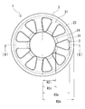
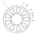
- FIG. 1 is a schematic top view of a core according to the embodiment.
- FIG. 2 is a schematic sectional view taken along the line II-II of FIG.
- FIG. 3 is a partially enlarged schematic sectional view of FIG.
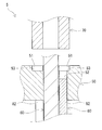
- FIG. 4 is a schematic cross-sectional view showing an example of a mold for molding the core according to the embodiment.
- FIG. 5 is a schematic top view of the die.
- FIG. 6 is a schematic sectional view taken along the line VI-VI of FIG.
- FIG. 7 is a partially enlarged schematic sectional view of FIG.
- FIG. 8 is a schematic top view of the lower punch.
- FIG. 9 is a schematic sectional view taken along line IX-IX in FIG. FIG.
- FIG. 10 is a partially enlarged schematic cross-sectional view showing a state in which the core is molded by the mold.
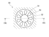
- FIG. 11 is a schematic top view of the stator according to the embodiment.
- FIG. 12 is a schematic cross-sectional view of the rotary electric machine according to the embodiment.
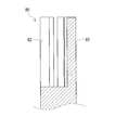
- FIG. 13A is a schematic top view showing an example of a core according to a modification.
- FIG. 13B is a schematic sectional view of a rotating electric machine using the core shown in FIG. 13A.
- FIG. 14A is a schematic top view showing another example of the core according to the modification.
- FIG. 14B is a schematic sectional view of a rotating electric machine using the core shown in FIG. 14A.
- One of the purposes of the present disclosure is to provide a core capable of improving magnetic characteristics. Another object of the present disclosure is to provide a stator including the core. Further, another object of the present disclosure is to provide a rotating electric machine including the above stator.
- the core of the present disclosure can improve magnetic properties.
- the stator of the present disclosure has excellent magnetic characteristics of the core.
- the rotating electric machine of this indication is excellent in efficiency.
- a shortcut may be made between the circumferential surface of the tooth and the first plane of the back yoke. That is, a leakage magnetic flux is likely to occur at the corner between the tooth and the back yoke.
- the leakage magnetic flux is generated in the core of the rotating electric machine, the torque is decreased, and the core loss is increased, which causes the efficiency to be decreased.
- the inventors tried to mold the end face of the tooth with the lower punch and the first plane of the back yoke with the die using a stepped die.
- the first curved surface portion can be formed at the corner portion between the tooth and the back yoke, and the magnetic flux leakage from the core generated at the corner portion between the tooth and the back yoke can be reduced as compared with the conventional core described above. I found it. This is because by forming the first curved surface portion at the corner between the tooth and the back yoke, the leakage magnetic flux short-cut between the circumferential surface of the tooth and the first flat surface of the back yoke is reduced.
- the core having the first curved surface portion at the corner between the tooth and the back yoke in the axial gap type rotary electric machine it is possible to suppress the decrease in torque due to the leakage magnetic flux and the loss in the core. Therefore, by having the first curved surface portion, it is possible to improve the magnetic characteristics of the core and thus improve the efficiency of the rotating electric machine.
- the core according to the embodiment of the present disclosure is A core used in an axial gap type rotating electrical machine, An annular back yoke, A plurality of teeth projecting in an axial direction perpendicular to the first plane of the back yoke, The plurality of teeth are provided at intervals in the circumferential direction of the first plane, The back yoke and the teeth are formed of a powder compact molded integrally.
- a first curved surface portion that connects the peripheral surface of the teeth and the first plane of the back yoke, The radius of curvature of the first curved surface portion is 0.2 mm or more and 1.5 mm or less.
- the core of the present disclosure described above has the first curved surface portion at the corner portion between the tooth and the back yoke, so that the leakage magnetic flux generated at the corner portion between the tooth and the back yoke can be reduced. Therefore, the core can improve the magnetic characteristics.
- the radius of curvature of the first curved surface portion is 0.2 mm or more, the leakage magnetic flux can be effectively reduced.
- the radius of curvature of the first curved surface portion is 1.5 mm or less, a space for the coil arranged on the tooth can be secured, and the space factor of the coil can be improved. As a result, it is possible to suppress a decrease in the number of turns of the coil, and thus a decrease in torque of the rotating electric machine can be suppressed.
- the radius of curvature of each of the outer curved surface portion and the inner curved surface portion may be 0.5 mm or more.
- the above core which is a compacted body, is formed by compressing soft magnetic powder with a mold.
- the teeth may be formed by the lower punch and the back yoke may be formed by the die. Due to the molding pressure when molding the core using the mold, bending stress tends to concentrate on the corners of the mold, especially the die, and cracks may occur at the corners of the mold.
- the curvature radius of each of the outer curved surface portion and the inner curved surface portion of the back yoke is 0.5 mm or more, so that stress concentration at the corners of the mold can be relaxed. Therefore, the said form can suppress the damage of a metal mold
- the upper limit of the radius of curvature of each of the outer curved surface portion and the inner curved surface portion is not particularly limited, but is, for example, 5.0 mm or less. As the respective radii of curvature of the outer curved surface portion and the inner curved surface portion increase, the lengths of the linear portions of the outer peripheral surface and the inner peripheral surface of the back yoke become shorter than the thickness of the back yoke. If the radius of curvature of each of the outer curved surface portion and the inner curved surface portion is 5.0 mm or less, it is easy to secure the length of the straight portion of the outer peripheral surface and the inner peripheral surface of the back yoke.
- the radius of curvature of the outer curved surface portion may be different from the radius of curvature of the inner curved surface portion.
- the radius of curvature of the outer curved surface portion and the inner curved surface portion of the back yoke may be different.
- the outer curved surface and the inner curved surface have different radii of curvature, it is preferable that the outer curved surface has a larger radius of curvature than the inner curved surface.
- the said form is easy to suppress the damage of a metal mold
- the rotating electric machine is configured using the core, the magnetic flux tends to flow more easily on the inner peripheral side of the back yoke than on the outer peripheral side. Since the radius of curvature of the outer curved surface portion is larger than the radius of curvature of the inner curved surface portion, it becomes easy to secure the effective magnetic path area of the back yoke. As a result, it is possible to suppress the concentration of magnetic flux on the inner peripheral side of the back yoke, and to expect the effect of improving the torque and efficiency of the rotating electric machine.
- At least one of the outer peripheral surface and the inner peripheral surface of the back yoke has a linear portion extending along the axial direction, The length of the straight portion may be 15% or more of the thickness of the back yoke.
- the outer peripheral surface of the back yoke When housing the above core in a case to configure a rotating electric machine, the outer peripheral surface of the back yoke may be fitted to the inner peripheral surface of the case.
- the linear portion of the outer peripheral surface makes surface contact with the inner peripheral surface of the case, so that the core is easily fixed to the case.
- a bus bar that connects the coils may be attached inside the back yoke.
- the linear portion of the inner peripheral surface makes surface contact with the bus bar, which facilitates fixing the bus bar to the core.
- the length of the linear portion of at least one of the outer peripheral surface and the inner peripheral surface of the back yoke is 15% or more of the thickness of the back yoke, so that the case and the bus bar can be easily assembled to the core.
- the upper limit of the ratio of the length of the linear portion to the thickness of the back yoke is not particularly limited, but may be, for example, 75% or less of the thickness of the back yoke.
- the length of the straight portion may be, for example, 0.5 mm or more and 9 mm or less.
- the thickness of the back yoke is, for example, 1.5 mm or more and 10 mm or less.
- the difference between the radial dimension from the axial center of the back yoke to the outer peripheral surface and the radial dimension from the axial center of the back yoke to the surface located on the outer peripheral side of the teeth is 6.0 mm or less. Is mentioned.
- the area from the outer peripheral surface of the back yoke to the part where the teeth protrude is defined as the outer peripheral area.
- bending stress may act on the outer peripheral region of the back yoke. This stress may deform the outer peripheral region.
- the difference between the radial dimension from the axial center of the back yoke to the outer peripheral surface and the radial dimension from the axial center of the back yoke to the surface located on the outer peripheral side of the teeth is 6.0 mm or less. .
- the radial dimension of the outer peripheral region of the back yoke is reduced, and deformation of the outer peripheral region can be suppressed.
- the radial dimension from the axial center of the back yoke to the outer peripheral surface may be referred to as the “outer radius of the back yoke”.
- the radial dimension from the axial center of the back yoke to the surface located on the outer peripheral side of the tooth may be referred to as the “outer radius of the tooth”.
- the difference between the outer radius of the back yoke and the outer radius of the teeth is 6.0 mm or less, the compression area when molding the core using the mold becomes small. Therefore, since a high molding pressure can be applied, the density of the core can be increased.
- the difference between the outer radius of the back yoke and the outer radius of the teeth may be 4.0 mm or less and 3.0 mm or less.
- the area from the inner peripheral surface of the back yoke to the part where the teeth protrude is defined as the inner peripheral area.
- bending stress may act on the inner peripheral region of the back yoke. This stress may deform the inner peripheral region.
- the difference between the radial dimension from the axial center of the back yoke to the surface located on the inner peripheral side of the teeth and the radial dimension from the axial center of the back yoke to the inner peripheral surface is 7.0 mm or less. Is.
- the radial dimension of the inner peripheral region of the back yoke is reduced, and deformation of the inner peripheral region can be suppressed.
- the radial dimension from the axial center of the back yoke to the surface located on the inner peripheral side of the tooth may be referred to as the “inner radius of the tooth”.
- the radial dimension from the axial center of the back yoke to the inner peripheral surface may be referred to as the “inner radius of the back yoke”.
- the difference between the inner radius of the teeth and the inner radius of the back yoke is 7.0 mm or less, the compression area when molding the core using the mold becomes small. Therefore, since a high molding pressure can be applied, the density of the core can be increased.
- the difference between the inner radius of the tooth and the inner radius of the back yoke is further 5.0 mm or less and 4.0 mm or less.
- the back yoke is partially provided on at least one of the outer peripheral surface and the inner peripheral surface and has a convex portion protruding in the radial direction or a concave portion recessed in the radial direction.
- the above-described embodiment has the convex portion or the concave portion on the outer peripheral surface of the back yoke, and the convex portion or the concave portion can be used for positioning with respect to the case.
- a convex portion or a concave portion is provided on the outer peripheral surface of the back yoke, and a concave portion or a convex portion corresponding to the convex portion or the concave portion is provided on the inner peripheral surface of the case.
- the core can be positioned with respect to the case by fitting the convex portion and the concave portion.
- the bus bar may be arranged inside the back yoke. Since the back yoke has a convex portion or a concave portion on its inner peripheral surface, the convex portion or the concave portion can be used for positioning the bus bar. For example, a convex portion or a concave portion is provided on the inner peripheral surface of the back yoke, and a concave portion or a convex portion corresponding to the convex portion or the concave portion is provided on the bus bar.
- the bus bar can be positioned with respect to the core by fitting the convex portion and the concave portion.
- the green compact is composed of an aggregate of a plurality of coated soft magnetic particles having an insulating coating on the surface of the soft magnetic particles,
- the soft magnetic particles are made of pure iron or at least one iron-based alloy selected from Fe-Si alloys, Fe-Al alloys, Fe-Cr-Al alloys and Fe-Cr-Si alloys. It may be iron-based particles.
- Pure iron or the above iron-based alloy is relatively soft. Therefore, when the soft magnetic particles are pure iron or iron-based particles made of the above iron-based alloy, the soft magnetic particles are easily deformed during the molding of the powder compact. Therefore, the said form can obtain a high-density and high dimensional-accuracy powder compact. By increasing the density of the powder compact, the mechanical strength and magnetic properties of the core can be improved. Further, by providing an insulating coating on the surface of the soft magnetic particles, the electrical insulation between the soft magnetic particles can be enhanced. Therefore, the core iron loss due to the eddy current loss can be reduced.
- the insulating coating comprises a phosphate coating.
- the phosphate coating has high adhesion to iron-based particles and is excellent in deformability. Therefore, when the insulating coating contains the phosphate coating, it is easy to follow the deformation of the iron-based particles during the molding of the powder compact. Therefore, in the above embodiment, the insulating coating is less likely to be damaged and the core iron loss can be reduced.
- the relative density of the green compact is 90% or more.
- the relative density of the green compact is 90% or more, so that the green compact has a high density.
- the core according to the embodiment of the present disclosure is A core used in an axial gap type rotating electrical machine, An annular back yoke, A plurality of teeth projecting in an axial direction perpendicular to the first plane of the back yoke, The plurality of teeth are provided at intervals in the circumferential direction of the first plane, The back yoke and the teeth are formed of a powder compact molded integrally.
- a first curved surface portion that connects the peripheral surface of the teeth and the first plane of the back yoke
- the radius of curvature of the first curved surface portion is 0.2 mm or more and 1.5 mm or less
- Each of the radius of curvature of the outer curved surface portion and the inner curved surface portion is 0.5 mm or more
- At least one of the outer peripheral surface and the inner peripheral surface of the back yoke has a linear portion extending along the axial direction, The length of the linear portion is 15% or more of the thickness of the back yoke.
- the core of the present disclosure described above has the first curved surface portion at the corner portion between the tooth and the back yoke, so that the leakage magnetic flux generated at the corner portion between the tooth and the back yoke can be reduced. Therefore, the core can improve the magnetic characteristics. Particularly, when the radius of curvature of the first curved surface portion is 0.2 mm or more, the leakage magnetic flux can be effectively reduced. Further, since the radius of curvature of the first curved surface portion is 1.5 mm or less, a space for the coil arranged on the tooth can be secured, and the space factor of the coil can be improved. As a result, it is possible to suppress a decrease in the number of turns of the coil, and thus a decrease in torque of the rotating electric machine can be suppressed.
- the length of the linear portion of at least one of the outer peripheral surface and the inner peripheral surface of the back yoke is 15% or more of the thickness of the back yoke, so that Assembly of the case and bus bar becomes easy.
- the stator according to the embodiment of the present disclosure is A stator of an axial gap type rotary electric machine, A core according to any one of (1) to (11) above, And a coil arranged on each tooth of the core.
- the above stator has excellent magnetic characteristics of the core. This is because the magnetic characteristics of the core can be improved by including the core according to the embodiment.
- a rotating electrical machine is An axial gap type rotating electric machine comprising a rotor and a stator, wherein the rotor and the stator are arranged to face each other in the axial direction,
- the stator is the stator according to (12) above.
- the above rotating electric machine has excellent efficiency. This is because the magnetic characteristics of the core are excellent by including the stator according to the embodiment.
- the core 1 according to the embodiment will be described with reference to FIGS. 1 to 3.
- the core 1 is used for an axial gap type rotating electric machine.
- the core 1 includes an annular back yoke 2 and a plurality of teeth 3 protruding from the back yoke 2.
- One of the characteristics of the core 1 is that it has a first curved surface portion 31 at the corner between the tooth 3 and the back yoke 2, as shown in FIGS. In the following description, when the core 1 is described, the side on which the teeth 3 project is up and the opposite side is down.
- the back yoke 2 shown in FIG. 1 has an annular plate shape. As shown in FIG. 2, in the back yoke 2, one of the planes, that is, the upper surface is the first plane 21, and the surface opposite to the first plane 21, that is, the lower surface is the second plane 22. As shown in FIG. 2, the teeth 3 are provided on the first plane 21 of the back yoke 2 so as to project therefrom.
- the thickness of the back yoke 2 is, for example, 1.5 mm or more and 10 mm or less, and further 2.0 mm or more and 7.0 mm or less. In FIG. 2, the thickness of the back yoke 2 is indicated by T2.
- the first plane 21 and the second plane 22 are planes along a direction orthogonal to the axial direction of the back yoke 2.
- an outer curved surface portion 23 connecting the first flat surface 21 and the outer peripheral surface of the back yoke 2 is provided at a corner portion of the outer peripheral edge of the first flat surface 21, as shown in FIG.
- the outer curved surface portion 23 is an arc that is inscribed in the extension surface of the first plane 21 and the outer peripheral surface of the back yoke 2, in other words, an arc that is convex toward the line of intersection of both extension surfaces.
- an inner curved surface portion 24 that connects the first flat surface 21 and the inner peripheral surface of the back yoke 2 is provided at a corner portion of the inner peripheral edge of the first flat surface 21.
- the inner curved surface portion 24 is an arc that is inscribed in the extension surface of the first plane 21 and the inner peripheral surface of the back yoke 2, that is, an arc that is convex toward the line of intersection of both extension surfaces.
- the respective curvature radii of the outer curved surface portion 23 and the inner curved surface portion 24 are preferably 0.5 mm or more, more preferably 1.0 mm or more and 1.5 mm or more.
- the upper limit of each radius of curvature of the outer curved surface portion 23 and the inner curved surface portion 24 is, for example, 5.0 mm or less, further 4.0 mm or less, and 3.0 mm or less.
- the respective radii of curvature of the outer curved surface portion 23 and the inner curved surface portion 24 are, for example, preferably 10% or more and 85% or less, more preferably 20% or more and 60% or less of the thickness of the back yoke 2.
- the radius of curvature of the outer curved surface portion 23 and the radius of curvature of the inner curved surface portion 24 may be the same or different. In FIG. 2, the radius of curvature of the outer curved surface portion 23 and the radius of curvature of the inner curved surface portion 24 are the same.
- each of the outer curved surface portion 23 and the inner curved surface portion 24 is 0.5 mm or more, when the core 1 is molded using the mold, stress concentration at the corners of the mold can be relaxed. Therefore, damage to the mold can be suppressed. The reason for this will be described later. If the radius of curvature of each of the outer curved surface portion 23 and the inner curved surface portion 24 is 5.0 mm or less, it is easy to secure the length of the linear portions 25 and 26 on the outer peripheral surface and the inner peripheral surface of the back yoke 2. This is because when the radius of curvature of the outer curved surface portion 23 or the inner curved surface portion 24 is increased, the length of the linear portions 25 and 26 on the outer peripheral surface or the inner peripheral surface becomes shorter than the thickness of the back yoke 2.
- the outer curved surface portion 23 and the inner curved surface portion 24 have different radii of curvature, it is preferable that the outer curved surface portion 23 has a larger radius of curvature than the inner curved surface portion 24.
- the outer edge corner of the mold for molding the outer peripheral corner of the back yoke 2 is the inner edge of the mold for molding the inner peripheral corner of the back yoke 2.
- the stress tends to be higher than the area.
- the radius of curvature of the outer curved surface portion 23 is larger than the radius of curvature of the inner curved surface portion 24, stress concentration at the outer edge corner of the mold can be effectively relaxed. Therefore, it is easy to suppress damage to the mold.
- At least one of the outer peripheral surface and the inner peripheral surface of the back yoke 2 preferably has a linear portion extending along the axial direction.
- linear portions 25 and 26 are provided on the outer peripheral surface and the inner peripheral surface.
- the length of the linear portions 25 and 26 is preferably, for example, 15% or more of the thickness of the back yoke 2, and more preferably 25% or more.
- the outer peripheral surface of the back yoke 2 When housing the core 1 in the case, the outer peripheral surface of the back yoke 2 may be fitted to the inner peripheral surface of the case.
- the linear portion 25 When the linear portion 25 is provided on the outer peripheral surface of the back yoke 2, the linear portion 25 makes surface contact with the inner peripheral surface of the case, so that the core 1 is easily fixed to the case.
- a bus bar When the rotary electric machine is configured using the core 1, a bus bar may be provided inside the back yoke 2.
- the linear portion 26 makes surface contact with the bus bar, so that the bus bar is easily fixed to the core 1. Since the length of the straight portions 25 and 26 is 15% or more of the thickness of the back yoke 2, the case and the bus bar can be easily assembled to the core 1.
- the upper limit of the ratio of the lengths of the straight portions 25 and 26 to the thickness of the back yoke 2 is, for example, 90% or less, and further 80% or less of the thickness of the back yoke 2.
- the length of the linear portions 25 and 26 is, for example, 0.5 mm or more and 9 mm or less, and further 0.8 mm or more and 8.0 mm or less.
- the teeth 3 are provided on the first plane 21 of the back yoke 2 at intervals in the circumferential direction. As shown in FIG. 2, the teeth 3 project from the first plane 21 in the axial direction of the back yoke 2. Specifically, the teeth 3 project in a direction perpendicular to the first plane 21.
- the number of teeth 3 may be appropriately determined, and is, for example, 3 or more, and further 6 or more. In this example, as shown in FIG. 1, nine teeth 3 are arranged at equal intervals in the circumferential direction.
- the shape of the tooth 3 is not particularly limited, and may be various shapes such as a columnar shape and a polygonal columnar shape. In this example, the tooth 3 has a triangular prism shape.
- the shape of the tooth 3 may be a quadrangular prism such as a trapezoidal prism.
- a corner portion between the tooth 3 and the back yoke 2 has a first curved surface portion 31 that connects the peripheral surface of the tooth 3 and the first flat surface 21 of the back yoke.
- the radius of curvature of the first curved surface portion 31 is 0.2 mm or more and 1.5 mm or less, preferably 0.3 mm or more, and more preferably 0.4 mm or more and 1.2 mm or less.
- a coil 110 is arranged on the peripheral surface of the tooth 3 as shown in FIG. By passing an electric current through the coil 110, a magnetic flux flows through the core 1 to form a magnetic path.
- the radius of curvature of the first curved surface portion 31 is 0.2 mm or more, the leakage magnetic flux generated at the corner portion between the tooth 3 and the back yoke 2 can be reduced. Further, since the radius of curvature of the first curved surface portion 31 is 1.5 mm or less, it is easy to secure a space for the coil 110 arranged on the tooth 3. Therefore, the decrease in the number of turns of the coil 110 can be suppressed.
- an insulating coating film (not shown) may be applied to the surface of the core 1.
- the insulating coating film can be formed by coating a resin having electric insulation.
- the resin that constitutes the insulating coating film include epoxy resin, fluorine resin, and polyimide resin.
- the insulating coating film may be provided on at least the surface of the core 1 that is in contact with the coil 110.
- the insulating coating film may be provided on the peripheral surface of the tooth 3 and the first flat surface 21 of the back yoke 2.
- An insulator (not shown) may be interposed between the core 1 and the coil 110.
- the difference between the outer radius of the back yoke 2 and the outer radius of the teeth 3 is preferably 0 mm or more and 6.0 mm or less, and more preferably 4.0 mm or less and 3.0 mm or less.
- the outer radius of the back yoke 2 means the radial dimension from the axial center of the back yoke 2 to the outer peripheral surface.
- the outer radius of the tooth 3 means the radial dimension from the axial center of the back yoke 2 to the surface located on the outer peripheral side of the tooth 3.
- the outer radius of the back yoke 2 is indicated by R2o
- the outer radius of the tooth 3 is indicated by R3o.
- the outer circumferential region 27 of the back yoke 2 has a radial dimension as shown in FIG. Get smaller.
- the outer peripheral region 27 of the back yoke 2 refers to a region from the outer peripheral surface of the back yoke 2 to a portion where the teeth 3 project. As the radial dimension of the outer peripheral region 27 of the back yoke 2 is smaller, the bending stress acting on the outer peripheral region 27 when the molded core 1 is taken out of the mold can be reduced. The reason for this will be described later.
- the difference between the outer radius R2o of the back yoke 2 and the outer radius R3o of the teeth 3 is 6.0 mm or less, and further 4.0 mm or less, the deformation of the outer peripheral region 27 due to the stress when taking out from the mold is suppressed. it can.
- the difference between the outer radius R2o of the back yoke 2 and the outer radius R3o of the teeth 3 is 6.0 mm or less, and further 3.0 mm or less, the compression area when molding the core using the mold is small. . Therefore, a high molding pressure can be applied, and the core 1 can be densified. The reason for this will be described later.
- the difference between the inner radius of the tooth 3 and the inner radius of the back yoke 2 is preferably 0 mm or more and 7.0 mm or less, more preferably 5.0 mm or less and 4.0 mm or less.
- the inner radius of the tooth 3 means the radial dimension from the axial center of the back yoke 2 to the surface located on the inner peripheral side of the tooth 3.
- the inner radius of the back yoke 2 means the radial dimension from the axial center of the back yoke 2 to the inner peripheral surface.
- the inner radius of the tooth 3 is indicated by R3i
- the inner radius of the back yoke 2 is indicated by R2i.
- the radial dimension of the inner peripheral region 28 of the back yoke 2 as shown in FIG. Becomes smaller.
- the inner peripheral region 28 of the back yoke 2 is a region from the inner peripheral surface of the back yoke 2 to the portion where the teeth 3 project. As the radial dimension of the inner peripheral region 28 of the back yoke 2 is smaller, the bending stress acting on the inner peripheral region 28 when the molded core 1 is taken out of the mold can be reduced. The reason for this will be described later.
- the difference between the inner radius R3i of the tooth 3 and the inner radius R2i of the back yoke 2 is 7.0 mm or less, and further 5.0 mm or less, the deformation of the inner peripheral region 28 due to the stress at the time of taking out from the mold is prevented. Can be suppressed.
- the difference between the inner radius R3i of the tooth 3 and the inner radius R2i of the back yoke 2 is 7.0 mm or less, and further 4.0 mm or less, the compression area when molding the core using the mold becomes small. . Therefore, a high molding pressure can be applied, and the core 1 can be densified. The reason for this will be described later.
- the difference between the position of the end surface of the highest tooth 3 and the position of the end surface of the lowest tooth 3 is preferably 0.2 mm or less, for example.
- the position of the end surface of the tooth 3 means the axial height from the surface of the back yoke 2 to the end surface of the tooth 3 when the second flat surface 22, that is, the lower surface, is placed on the flat surface.
- the position H3 Since the difference between the position of the end surface of the tooth 3 having the highest height and the position of the end surface of the tooth 3 having the lowest height is 0.2 mm or less, the variation in the height of each end surface of the tooth 3 is small. As will be described later, when the rotating electric machine 300 shown in FIG.
- each end surface of the tooth 3 is arranged so as to face the magnet 220 of the rotor 200. Since the variation in the height of each end face of the tooth 3 is small, the variation in the distance between each end face of the tooth 3 and the rotor 200 can be reduced in the rotary electric machine 300. As a result, it is possible to suppress the deterioration of the characteristics of the rotary electric machine 300, such as the reduction of cogging.
- the back yoke 2 and the teeth 3 are composed of a powder compact that is integrally molded. That is, the core 1 is composed of a powder compact.
- the green compact is formed by compressing soft magnetic powder.
- the soft magnetic powder is an aggregate of a plurality of coated soft magnetic particles having an insulating coating on the surface of the soft magnetic particles. That is, the green compact is composed of an aggregate of a plurality of coated soft magnetic particles.
- the powder compact forming the core 1 is substantially composed only of soft magnetic powder composed of coated soft magnetic particles.
- the soft magnetic particles are, for example, pure iron having a purity of 99% by mass or more, or Fe (iron) -Si (silicon) alloy, Fe (iron) -Al (aluminum) alloy, Fe (iron) -Cr (chromium). ) -Al (aluminum) -based alloy and Fe (iron) -Cr (chromium) -Si (silicon) -based alloy, which is an iron-based particle made of at least one iron-based alloy. Pure iron or the above iron-based alloy is relatively soft. Therefore, when the soft magnetic particles are pure iron or iron-based particles made of the above iron-based alloy, the soft magnetic particles are easily deformed when the powder compact forming the core 1 is molded.
- the insulating coating includes phosphate coating and silica coating.
- the insulating coating preferably contains a phosphate coating.
- the phosphate coating has high adhesion to iron-based particles and is excellent in deformability. Therefore, when the insulating coating contains the phosphate coating, it is easy to follow the deformation of the iron-based particles during the molding of the powder compact. Therefore, the insulating coating is less likely to be damaged, and the iron loss of the core 1 can be reduced.
- the relative density of the green compact forming the core 1 is preferably 90% or more. By increasing the density of the powder compact, the mechanical strength and magnetic properties of the core 1 can be improved. A more preferable relative density is 93% or more.
- the relative density is the ratio (%) of the actual density of the green compact to the true density of the green compact.
- the true density of the green compact can be determined from the true density of the soft magnetic powder.
- the relative density of the green compact can be determined as, for example, [(molding density of green compact / true density of green compact) ⁇ 100].
- the compacting density of the green compact is obtained by immersing the green compact in oil to impregnate the green compact with [oil density x (mass of green compact before oil impregnation / powder after oil impregnation The mass of the molded product)].
- the oil impregnation density is a value obtained by dividing the mass of the powder compact after impregnation with the volume.
- the volume of the green compact can be typically measured by a liquid replacement method.
- the core 1 made of a powder compact can be manufactured by compressing and molding the soft magnetic powder with a mold.
- the mold 5 used for manufacturing the core 1 will be described with reference to FIGS. 4 to 10.
- the die 5 includes a die 50, a core rod 60 arranged in the die 50, and upper and lower punches 70 and 80 fitted in the die 50.
- the die 50 is a stepped die. As shown in FIGS. 5 and 6, the die 50 includes a first molding portion 51 and a plurality of second molding portions 52, and a step portion 53 is provided between the first molding portion 51 and the second molding portion 52.
- the first molding portion 51 is a portion that forms a space for molding the back yoke 2 shown in FIGS. 1 and 2.
- the second molding portion 52 is a portion that forms a space for molding the teeth 3 shown in FIGS. 1 and 2.
- the first molding portion 51 is provided on the upper side of the die 50.
- the second molding portion 52 is provided below the die 50 and continuously to the first molding portion 51.
- the core rod 60 is coaxially arranged in the first molding portion 51 of the die 50.
- the upper punch 70 is located on the upper side of the die 50 and is fitted into the first molding portion 51 from above.
- the lower punch 80 is located below the die 50, and is fitted into the second molding portion 52 from below.
- the lower punch 80 has a plurality of punch portions 82 inserted into the second molding portion 52 shown in FIGS. 5 and 6 on the tip side thereof.
- the base end side of the punch portion 82 is integrally formed.
- the first molding portion 51 of the die 50, the core rod 60 and the upper punch 70 form an annular space for molding the back yoke 2 shown in FIGS. 1 and 2.
- the second molding section 52 of the die 50 and the punch section 82 of the lower punch 80 form a columnar space for molding the tooth 3 shown in FIGS. 1 and 2.
- the upper punch 70 is lowered, and the raw material powder is pressed by the upper punch 70 from above the first molding portion 51.
- the inner peripheral surface of the first molding portion 51 molds the outer peripheral surface of the back yoke 2
- the surface of the stepped portion 53 molds the back yoke 2 of the back yoke 2.
- the first plane 21 is formed.
- the outer peripheral surface of the core rod 60 forms the inner peripheral surface of the back yoke 2.
- the second flat surface 22 of the back yoke 2 is formed by the end surface of the upper punch 70. Further, the inner peripheral surface of the second molding portion 52 molds the peripheral surface of the tooth 3.
- the end surface of the tooth 3 is formed by the end surface of the punch portion 82 of the lower punch 80.
- the upper punch 70 is raised and the die 50 and the core rod 60 are lowered with respect to the lower punch 80. Then, the core 1 is extracted from the die 50 while supporting the end faces of the teeth 3 with the punch portion 82.
- the raw material powder is mainly composed of soft magnetic powder.
- the main component means that the content of the raw material powder is 90% by mass or more when the mass of the raw material powder is 100% by mass.
- a lubricant or binder resin may be added to the raw material powder as needed.
- the average particle size of the soft magnetic powder may be, for example, 20 ⁇ m or more and 300 ⁇ m or less, and further 40 ⁇ m or more and 250 ⁇ m or less. By setting the average particle size of the soft magnetic powder within the above range, handling is easy and compression molding is easy.
- the average particle diameter of the soft magnetic powder means a particle diameter measured by a laser diffraction / scattering type particle diameter / particle size distribution measuring device and having an integrated mass of 50% of the mass of all particles.
- the core 1 can be densified by increasing the molding pressure when compressing the raw material powder containing the soft magnetic powder.
- the molding pressure is, for example, 700 MPa or more, and further 800 MPa or more.
- the first corner portion 531 between the surface of the step portion 53 and the inner peripheral surface of the second molding portion 52 is formed on the first curved surface portion 31 of the core 1 shown in FIG. It is formed in a corresponding curved surface.
- the radius of curvature of the first corner portion 531 is 0.2 mm or more and 1.5 mm or less. Since the first corner portion 531 is formed into a curved surface, the first curved surface portion 31 is formed at the corner portion between the tooth 3 and the back yoke 2.
- the outer edge corner portion 532 and the inner edge corner portion 533 of the step portion 53 are formed in a curved surface shape corresponding to the outer curved surface portion 23 and the inner curved surface portion 24 of the back yoke 2 shown in FIG. There is.
- Each radius of curvature of the outer edge corner portion 532 and the inner edge corner portion 533 is, for example, 0.5 mm or more and 5.0 mm or less.
- the second flat surface 22 of the back yoke 2 pressed by the end surface of the upper punch 70 becomes the compression surface, as shown in FIG.
- the surface of the stepped portion 53 and the end surface of the punch portion 82 of the lower punch 80 serve as pressure receiving surfaces.
- the pressure acting on the surface of the step portion 53 is received by the outer edge corner portion 532 and the inner edge corner portion 533, bending stress is likely to concentrate on the outer edge corner portion 532 and the inner edge corner portion 533. Since the radius of curvature of each of the outer edge corner portion 532 and the inner edge corner portion 533 is 0.5 mm or more, stress concentration can be relaxed. Therefore, damage to the die 50 can be suppressed.
- the punch portion 82 supports only the end faces of the teeth 3 and lowers the die 50 so that the core 1 is relatively pushed up and pulled out from the die 50.
- the outer peripheral surface of the back yoke 2 slides on the inner peripheral surface of the first molding portion 51.
- the inner peripheral surface of the back yoke 2 slides on the outer peripheral surface of the core rod 60. Therefore, bending stress acts on the outer peripheral region 27 and the inner peripheral region 28 of the back yoke 2 which project from the tooth 3 shown in FIG. 3 to the outside and the inside in the radial direction.
- the radial dimension of the outer peripheral region 27 is reduced. Further, since the difference between the inner radius R3i of the tooth 3 shown in FIG. 1 and the inner radius R2i of the back yoke 2 is 7.0 mm or less, the radial dimension of the inner peripheral region 28 is reduced. Therefore, when the core 1 is taken out from the mold 5, the bending stress acting on the outer peripheral region 27 and the inner peripheral region 28 can be reduced, so that the deformation of the outer peripheral region 27 and the inner peripheral region 28 can be suppressed.
- One of the difference between the outer radius R2o of the back yoke 2 and the outer radius R3o of the teeth 3 and the difference between the inner radius R3i of the teeth 3 and the inner radius R2i of the back yoke 2 is preferably 4.0 mm or less, and further 3 If it is 0.0 mm or less, the area of the second plane 22 can be reduced.
- the difference between the outer radius R2o of the back yoke 2 and the outer radius R3o of the tooth 3 and the difference between the inner radius R3i of the tooth 3 and the inner radius R2i of the back yoke 2 may be the same or different.
- Good. 1 and 2 the difference between the outer radius R2o of the back yoke 2 and the outer radius R3o of the tooth 3 is larger than the difference between the inner radius R3i of the tooth 3 and the inner radius R2i of the back yoke 2.
- the stator 100 is used for an axial gap type rotating electric machine.
- the stator 100 includes a core 1 and a coil 110 arranged on each tooth 3 of the core 1.
- the coil 110 is configured by winding a winding around the tooth 3.
- the rotating electrical machine 300 may be a motor or a generator.
- the rotary electric machine 300 includes a rotor 200 and a stator 100.
- the rotary electric machine 300 is an axial gap type rotary electric machine in which the rotor 200 and the stator 100 are arranged to face each other in the rotation axis direction.
- the stator 100 and the rotor 200 are housed in a cylindrical case 310.
- Disc-shaped plates 320 are attached to both ends of the case 310, respectively.
- a through hole is formed at the center of both plates 320, and the rotary shaft 330 penetrates through the case 310.
- the rotor 200 includes a plurality of flat plate-shaped magnets 220 and an annular holding plate 210 that supports the magnets 220.
- the planar shape of the magnet 220 is a shape substantially corresponding to the end surface of the tooth 3. When the end surface of the tooth 3 has a triangular shape, the planar shape of the magnet 220 may be, for example, a triangular shape or a trapezoidal shape.
- the holding plate 210 is fixed to the rotating shaft 330 and rotates together with the rotating shaft 330.
- Each magnet 220 is embedded in the holding plate 210.
- Each magnet 220 may be fixed to the holding plate 210 with an adhesive.
- the magnets 220 are arranged at equal intervals in the circumferential direction of the rotating shaft 330.
- the magnet 220 is magnetized in the axial direction of the rotating shaft 330. Magnetization directions of the magnets 220 adjacent to each other in the circumferential direction are opposite to each other.
- the stator 100 is arranged such that the end surfaces of the teeth 3 face the magnets 220 of the rotor 200.
- the stator 100 is fixed to the case 310 by fitting the outer peripheral surface of the back yoke 2 of the core 1 to the inner peripheral surface of the case 310.
- the linear portion 25 is provided on the outer peripheral surface of the back yoke 2, it is easy to fix the core 1 forming the stator 100 to the case 310.
- An annular bearing 340 that rotatably supports the rotating shaft 330 is arranged on the inner peripheral side of the back yoke 2.
- At least one of the outer peripheral surface and the inner peripheral surface of the back yoke 2 may have a convex portion or a concave portion.
- An example in which the convex portion 41 or the concave portion 42 is provided on the outer peripheral surface of the back yoke 2 will be described with reference to FIGS. 13A and 13B, 14A and 14B.
- a convex portion 41 protruding in the radial direction is formed on the outer peripheral surface of the back yoke 2.
- the convex portion 41 is partially provided on the outer peripheral surface of the back yoke 2.
- the number of the convex portions 41 is one, but the number of the convex portions 41 may be plural.
- the shape of the convex portion 41 when the core 1 is viewed in plan is rectangular.
- the shape of the convex portion 41 is not limited to the rectangular shape, and may be, for example, a semicircular shape, a triangular shape, or a trapezoidal shape.
- a recess 311 corresponding to the protrusion 41 on the outer peripheral surface of the back yoke 2 is provided on the inner peripheral surface of the case 310 as shown in FIG. 13B.
- the core 1 of the stator 100 can be positioned with respect to the case 310 by fitting the convex portion 41 and the concave portion 311 together.
- a recess 42 that is recessed in the radial direction is formed on the outer peripheral surface of the back yoke 2.
- the recess 42 is partially provided on the outer peripheral surface of the back yoke 2.
- the shape of the recess 42 when the core 1 is viewed in plan is rectangular.
- the shape of the recess 42 is not limited to the rectangular shape, and may be, for example, a semicircular shape, a triangular shape, or a trapezoidal shape.
- the convex portion 312 corresponding to the concave portion 42 on the outer peripheral surface of the back yoke 2 is provided on the inner peripheral surface of the case 310.
- the core 1 of the stator 100 can be positioned with respect to the case 310 by fitting the concave portion 42 and the convex portion 312 together.
- the convex portion 41 or the concave portion 42 is provided on the outer peripheral surface of the back yoke 2 has been described, but the convex portion or the concave portion is partially formed on the inner peripheral surface of the back yoke 2. It may be provided.
- the number of convex portions or concave portions may be one or more and is not particularly limited.
- the shape of the convex portion or the concave portion when the core 1 is viewed in a plan view is not limited to a rectangular shape, and may be, for example, a semicircular shape, a triangular shape, or a trapezoidal shape.
- a bus bar (not shown) may be placed inside the back yoke 2.
- a convex portion or a concave portion is provided on the inner peripheral surface of the back yoke 2
- a concave portion or a convex portion corresponding to the convex portion or the concave portion is provided on the outer peripheral surface of the bus bar.
- the bus bar can be positioned with respect to the core 1 by fitting the protrusions and the recesses.
- the convex portion or the concave portion can be used for positioning.
- the shape of the convex portion or the concave portion when the core 1 is viewed in plan has at least one linear portion.
- the straight line portion is a straight line portion of the contour of the convex portion or the concave portion when the core 1 is viewed in a plan view. Positioning accuracy can be improved by the convex portion or the concave portion having a linear portion.
- the core 1, the stator 100, and the rotary electric machine 300 of the above-described embodiment have the following effects.
- the core 1 has the first curved surface portion having a radius of curvature of 0.2 mm or more at the corner portion between the tooth 3 and the back yoke 2, so that the leakage magnetic flux generated at the corner portion between the tooth 3 and the back yoke 2 can be reduced. . Therefore, the loss due to the leakage magnetic flux can be suppressed. Further, since the radius of curvature of the first curved surface portion 31 is 1.5 mm or less, the decrease in the number of turns of the coil 110 can be suppressed. As a result, it is possible to suppress a decrease in the torque of the rotary electric machine 300.
- stator 100 includes the core 1, it has excellent magnetic characteristics.
- the rotating electrical machine 300 is excellent in efficiency by including the stator 100.
- Test Example 1 A core having the same structure as that of the core 1 described in the embodiment was manufactured and evaluated.
- Test Example 1 a plurality of cores having different curvature radii of the first curved surface portion 31 were prepared. Sample No. 1-0 to No. 1-6.
- the stator 100 was manufactured by winding a coil around each tooth 3 of the prepared core 1 to form the coil 110. Then, using the produced stator 100, an axial gap type rotating electrical machine 300 was configured. This rotating electric machine 300 functions as a motor.
- the magnetic flux density distribution of the core when a current was passed through the coil was analyzed and the maximum magnetic flux density at the root of the tooth was determined.
- the electromagnetic field analysis software used is “JMAG” manufactured by JSOL. Table 1 shows the maximum magnetic flux density at the tooth root portion in each sample. In addition, core loss and motor torque were determined by electromagnetic field analysis. The results are also shown in Table 1.
- sample No. 1 having a radius of curvature of the first curved surface part of 0.2 mm or more. 1-1 to No. 1-6 sample No. 1 having a radius of curvature of 0 mm. It can be seen that the iron loss is smaller than that of 1-0. Sample No. with a radius of curvature of 0 mm It is considered that in 1-0, the magnetic flux short-circuited between the circumferential surface of the tooth and the first plane of the back yoke, and thus the iron loss due to the leakage magnetic flux increased.
- the sample No. 1-1 to No. In No. 1-6 since the radius of curvature is 0.2 mm or more, it is considered that the leakage flux short-cut is reduced and the iron loss due to the leakage flux is reduced.
- Sample No. 1-1 to No. From the comparison of 1-6, it can be seen that the core loss can be suppressed as the radius of curvature of the first curved surface portion increases. However, sample No. 1 having a radius of curvature of 2.0 mm. 1-6, sample No. 1 having a radius of curvature of 1.5 mm or less. 1-1 to No. It can be seen that the torque is reduced as compared with 1-5. This is sample No. In Nos. 1-6, since the radius of curvature is large, Sample No. 1-1 to No. The reason is that the number of turns of the coil is reduced compared to 1-5.
- the radius of curvature of the first curved surface portion is preferably 0.2 mm or more and 1.5 mm or less.
- Test Example 2 The stress distribution acting on the die 50 when the core 1 described in the embodiment is molded by the mold 5 was analyzed by CAE (Computer Aided Engineering). Then, the maximum stress generated in the outer edge corner portion 532 of the step portion 53 in the die 50 was obtained from the result of the stress analysis by CAE. In Test Example 2, the radius of curvature of the outer edge corner portion 532 was made different, and the maximum stress in each case was obtained. The results are shown in Table 2.
- the analysis conditions were set as follows.
- the molding pressure was 980 MPa.
- the physical properties of the die 50 were Young's modulus: 206000 MPa and Poisson's ratio: 0.3.
- the outer radius R2o of the back yoke 2 of the core 1 to be molded is 25 mm, the inner radius R2i is 10 mm, and the thickness T2 is 3.0 mm.
- the radius of curvature of the outer curved surface is preferably 0.5 mm or more.
- Test Example 3 In Test Example 3, the maximum stress generated at the inner edge corner portion 533 of the step portion 53 of the die 50 during core molding was obtained by the stress analysis by CAE as in Test Example 2. The results are shown in Table 3. The analysis conditions are the same as in Test Example 2.
- the radius of curvature of the inner curved surface is preferably 0.5 mm or more. Further, from the results of Tables 2 and 3, it can be seen that the maximum stress in core molding tends to be higher in the outer edge corners of the step in the die than in the inner edge corners. Therefore, it can be said that it is preferable to make the radius of curvature of the outer edge corner portion larger than that of the inner edge corner portion, that is, to make the radius of curvature of the outer curved surface portion larger than the radius of curvature of the inner curved surface portion.
- the radius of curvature of the outer curved surface portion larger than the radius of curvature of the inner curved surface portion in view of the fact that the magnetic flux flowing in the back yoke easily selectively passes through the inner peripheral side.
- [Appendix 1] A core used in an axial gap type rotating electrical machine, An annular back yoke, A plurality of teeth axially protruding from the first plane of the back yoke, The plurality of teeth are provided at intervals in the circumferential direction of the first plane, The back yoke and the teeth are formed of a powder compact molded integrally.
- a first curved surface portion that connects the peripheral surface of the teeth and the first plane of the back yoke, The radius of curvature of the first curved surface portion is 0.2 mm or more and 1.5 mm or less, core.
- the core according to appendix 1 has the first curved surface portion at the corner between the tooth and the back yoke, so that the leakage magnetic flux generated at the corner between the tooth and the back yoke can be reduced. Therefore, the core of Appendix 1 can improve the magnetic characteristics.
- the radius of curvature of the first curved surface portion is 0.2 mm or more, the leakage magnetic flux can be effectively reduced.
- the radius of curvature of the first curved surface portion is 1.5 mm or less, a space for the coil arranged on the tooth can be secured, and the space factor of the coil can be improved. As a result, it is possible to suppress a decrease in the number of turns of the coil, and thus a decrease in torque of the rotating electric machine can be suppressed.
- Appendix 2 An outer curved surface portion connecting between the first flat surface and the outer peripheral surface of the back yoke, An inner curved surface portion connecting between the first flat surface and the inner peripheral surface of the back yoke, The core according to appendix 1, wherein each of the outer curved surface portion and the inner curved surface portion has a radius of curvature of 0.5 mm or more and 5.0 mm or less.
- the above core which is a compacted body, is formed by compressing soft magnetic powder with a mold.
- bending stress is likely to be concentrated on the corners of the mold, especially the die, and cracks may occur at the corners of the mold.
- the stress concentration at the corners of the mold can be relaxed because the radius of curvature of each of the outer curved surface portion and the inner curved surface portion of the back yoke is 0.5 mm or more. Therefore, the said form can suppress the damage of a metal mold
- the lengths of the linear portions of the outer peripheral surface and the inner peripheral surface of the back yoke become shorter than the thickness of the back yoke. If the radius of curvature of each of the outer curved surface portion and the inner curved surface portion is 5.0 mm or less, it is easy to secure a large length of the straight portion of the outer peripheral surface and the inner peripheral surface of the back yoke.
- the green compact is composed of an aggregate of a plurality of coated soft magnetic particles having an insulating coating on the surface of the soft magnetic particles, The core according to Appendix 1, wherein the average particle diameter of the soft magnetic particles is 20 ⁇ m or more and 300 ⁇ m or less.
- the average particle size of the soft magnetic particles forming the green compact depends on the average particle size of the soft magnetic powder contained in the raw material powder.
- the average particle diameter of the soft magnetic particles is 20 ⁇ m or more and 300 ⁇ m or less, it is easy to obtain a compacted powder compact having a high density.
- the average particle diameter of the soft magnetic particles in the powder compact can be determined as follows. An arbitrary cross section of the green compact is observed with a microscope such as a scanning electron microscope (SEM) or an optical microscope. All soft magnetic particles existing in the observation visual field are extracted, and the area of each particle is measured. The diameter of a circle having an area equal to the area of each particle is calculated, and the average value is used as the average particle diameter of the soft magnetic particles.
- the size of the observation visual field is set so as to include, for example, 50 or more soft magnetic particles.
- the extraction of soft magnetic particles, the measurement of the area, and the calculation of the equivalent area circle equivalent diameter may be performed using image analysis software or the like.
- the green compact is composed of an aggregate of a plurality of coated soft magnetic particles having an insulating coating on the surface of the soft magnetic particles, The core according to Appendix 1, wherein the average particle size of the soft magnetic particles is 40 ⁇ m or more and 250 ⁇ m or less.
- the average particle diameter of the soft magnetic particles is 40 ⁇ m or more and 250 ⁇ m or less, it is easy to obtain a denser and denser powder compact.
- Appendix 5 The core according to appendix 1, wherein the green compact has a relative density of 93% or more.
- the relative density of the green compact is 93% or more, so the green compact has a high density.
- the mechanical strength and magnetic properties of the core can be improved.
Landscapes
- Engineering & Computer Science (AREA)
- Power Engineering (AREA)
- Iron Core Of Rotating Electric Machines (AREA)
- Permanent Magnet Type Synchronous Machine (AREA)
Abstract
アキシャルギャップ型の回転電機に用いられるコアであって、環状のバックヨークと、前記バックヨークの第一平面に対して垂直な軸方向に突出する複数のティースと、を備え、前記複数のティースは前記第一平面の周方向に間隔をあけて設けられ、前記バックヨークと前記ティースとは一体成形された圧粉成形体で構成されており、前記ティースと前記バックヨークとの角部に、前記ティースの周面と前記バックヨークの前記第一平面との間をつなぐ第一曲面部を有し、前記第一曲面部の曲率半径が0.2mm以上1.5mm以下であるコア。
Description
本開示は、コア、ステータ、及び回転電機に関する。
本出願は、2018年10月26日付の日本国出願の特願2018-202373号に基づく優先権を主張し、前記日本国出願に記載された全ての記載内容を援用するものである。
本出願は、2018年10月26日付の日本国出願の特願2018-202373号に基づく優先権を主張し、前記日本国出願に記載された全ての記載内容を援用するものである。
特許文献1、2は、ロータとステータとが軸方向に対向して配置されたアキシャルギャップ型のモータ(回転電機)を開示する。この種の回転電機に用いられるステータは、円環状のバックヨークと、バックヨークから軸方向に突出する複数のティースとを有するコアと、各ティースに配置されるコイルとを備える。複数のティースは、バックヨークの一面(上面)に周方向に間隔をあけて設けられる。
特許文献1には、バックヨークとティースとが一体成形された圧粉成形体でコアを構成することが記載されている。
本開示のコアは、
アキシャルギャップ型の回転電機に用いられるコアであって、
環状のバックヨークと、
前記バックヨークの第一平面に対して垂直な軸方向に突出する複数のティースと、を備え、
前記複数のティースは前記第一平面の周方向に間隔をあけて設けられ、
前記バックヨークと前記ティースとは一体成形された圧粉成形体で構成されており、
前記ティースと前記バックヨークとの角部に、前記ティースの周面と前記バックヨークの前記第一平面との間をつなぐ第一曲面部を有し、
前記第一曲面部の曲率半径が0.2mm以上1.5mm以下である。
アキシャルギャップ型の回転電機に用いられるコアであって、
環状のバックヨークと、
前記バックヨークの第一平面に対して垂直な軸方向に突出する複数のティースと、を備え、
前記複数のティースは前記第一平面の周方向に間隔をあけて設けられ、
前記バックヨークと前記ティースとは一体成形された圧粉成形体で構成されており、
前記ティースと前記バックヨークとの角部に、前記ティースの周面と前記バックヨークの前記第一平面との間をつなぐ第一曲面部を有し、
前記第一曲面部の曲率半径が0.2mm以上1.5mm以下である。
本開示のステータは、
アキシャルギャップ型の回転電機のステータであって、
本開示のコアと、
前記コアの各ティースに配置されるコイルと、を備える。
アキシャルギャップ型の回転電機のステータであって、
本開示のコアと、
前記コアの各ティースに配置されるコイルと、を備える。
本開示の回転電機は、
ロータとステータとを備え、前記ロータと前記ステータとが軸方向に対向して配置されたアキシャルギャップ型の回転電機であって、
前記ステータが本開示のステータである。
ロータとステータとを備え、前記ロータと前記ステータとが軸方向に対向して配置されたアキシャルギャップ型の回転電機であって、
前記ステータが本開示のステータである。
[本開示が解決しようとする課題]
アキシャルギャップ型の回転電機の効率を向上させることが望まれている。回転電機の効率を向上させる観点から、回転電機に用いられるコアの磁気特性を改善することが望まれる。
アキシャルギャップ型の回転電機の効率を向上させることが望まれている。回転電機の効率を向上させる観点から、回転電機に用いられるコアの磁気特性を改善することが望まれる。
本開示は、磁気特性を改善できるコアを提供することを目的の一つとする。また、本開示は、上記コアを備えるステータを提供することを目的の一つとする。更に、本開示は、上記ステータを備える回転電機を提供することを目的の一つとする。
[本開示の効果]
本開示のコアは磁気特性を改善できる。また、本開示のステータはコアの磁気特性に優れる。更に、本開示の回転電機は効率に優れる。
本開示のコアは磁気特性を改善できる。また、本開示のステータはコアの磁気特性に優れる。更に、本開示の回転電機は効率に優れる。
[本開示の実施形態の説明]
本発明者らは、アキシャルギャップ型の回転電機に用いられるコアの磁気特性について鋭意検討した結果、以下のような知見を得た。
本発明者らは、アキシャルギャップ型の回転電機に用いられるコアの磁気特性について鋭意検討した結果、以下のような知見を得た。
アキシャルギャップ型の回転電機において、コイルに電流を流すと、コアに磁束が流れて磁路が形成される。コアに流れる磁束が減少すると、回転電機のトルクが低下する。回転電機のコアにおいて、ティースでは軸方向に磁束が流れ、バックヨークでは周方向に磁束が流れる。そのため、ティースとバックヨークとの間で磁束の方向が変わる。
従来の圧粉成形体からなるコアでは、特許文献2にも記載があるように、金型を用いて成形する際、2つの下パンチを用い、ティースの端面と、ティースが突出するバックヨークの第一平面とをそれぞれ異なる下パンチで成形することが一般的である。この場合、パンチ強度などの観点から、ティースの周面と、ティースが突出するバックヨークの第一平面とが直交するように成形される。このようなコアでは、ティースの周面とバックヨークの第一平面とが直交するため、ティースとバックヨークとの間の角部を磁束が流れる際、磁束の一部がコアの外側を通ってティースの周面とバックヨークの第一平面との間をショートカットすることがある。つまり、ティースとバックヨークとの角部に漏れ磁束が発生し易い。回転電機のコアに漏れ磁束が発生すると、トルクの低下を招いたり、コアの損失が増大して効率の低下を招く。
本発明者らは、段付きダイを用いて、ティースの端面を下パンチで、バックヨークの第一平面をダイで成形することを試みた。これにより、ティースとバックヨークとの角部に第一曲面部を形成可能とし、上述した従来のコアに比較して、ティースとバックヨークとの角部に発生するコアの漏れ磁束を低減できることを見出した。これは、ティースとバックヨークとの角部に第一曲面部を形成することによって、ティースの周面とバックヨークの第一平面との間をショートカットする漏れ磁束が減少するためである。そして、ティースとバックヨークとの角部に第一曲面部を有するコアをアキシャルギャップ型の回転電機に用いることで、漏れ磁束によるトルクの低下やコアの損失を抑制できる。したがって、上記第一曲面部を有することで、コアの磁気特性を改善でき、ひいては回転電機の効率を向上させることが可能である。
本開示は、以上の知見に基づいてなされたものである。最初に本開示の実施態様を列記して説明する。
(1)本開示の実施形態に係るコアは、
アキシャルギャップ型の回転電機に用いられるコアであって、
環状のバックヨークと、
前記バックヨークの第一平面に対して垂直な軸方向に突出する複数のティースと、を備え、
前記複数のティースは前記第一平面の周方向に間隔をあけて設けられ、
前記バックヨークと前記ティースとは一体成形された圧粉成形体で構成されており、
前記ティースと前記バックヨークとの角部に、前記ティースの周面と前記バックヨークの前記第一平面との間をつなぐ第一曲面部を有し、
前記第一曲面部の曲率半径が0.2mm以上1.5mm以下である。
アキシャルギャップ型の回転電機に用いられるコアであって、
環状のバックヨークと、
前記バックヨークの第一平面に対して垂直な軸方向に突出する複数のティースと、を備え、
前記複数のティースは前記第一平面の周方向に間隔をあけて設けられ、
前記バックヨークと前記ティースとは一体成形された圧粉成形体で構成されており、
前記ティースと前記バックヨークとの角部に、前記ティースの周面と前記バックヨークの前記第一平面との間をつなぐ第一曲面部を有し、
前記第一曲面部の曲率半径が0.2mm以上1.5mm以下である。
上記本開示のコアは、ティースとバックヨークとの角部に第一曲面部を有することで、ティースとバックヨークとの角部に発生する漏れ磁束を低減できる。よって、上記コアは磁気特性を改善できる。第一曲面部の曲率半径が0.2mm以上であることで、漏れ磁束を効果的に低減できる。また、第一曲面部の曲率半径が1.5mm以下であることで、ティースに配置されるコイルのスペースを確保して、コイルの占積率の向上を図ることができる。これにより、コイルのターン数の減少を抑制することができるので、回転電機のトルクの低下を抑制できる。
(2)上記コアの一形態として、
前記第一平面と前記バックヨークの外周面との間をつなぐ外側曲面部と、
前記第一平面と前記バックヨークの内周面との間をつなぐ内側曲面部と、を有し、
前記外側曲面部及び前記内側曲面部の各曲率半径が0.5mm以上であることが挙げられる。
前記第一平面と前記バックヨークの外周面との間をつなぐ外側曲面部と、
前記第一平面と前記バックヨークの内周面との間をつなぐ内側曲面部と、を有し、
前記外側曲面部及び前記内側曲面部の各曲率半径が0.5mm以上であることが挙げられる。
圧粉成形体からなる上記コアは、金型で軟磁性粉末を圧縮して成形する。具体的には、ティースを下パンチで、バックヨークをダイで成形することが挙げられる。金型を用いてコアを成形する際の成形圧によって、金型、特にダイの角部に曲げ応力が集中し易く、金型の角部に亀裂が発生することがある。上記形態は、バックヨークの外側曲面部及び内側曲面部の各曲率半径が0.5mm以上であることで、金型の角部における応力集中を緩和できる。よって、上記形態は金型の破損を抑制できる。外側曲面部及び内側曲面部の各曲率半径の上限は、特に限定されないが、例えば5.0mm以下であることが挙げられる。外側曲面部及び内側曲面部の各曲率半径が大きくなると、バックヨークの厚みに対してバックヨークの外周面及び内周面の直線部の長さが短くなる。外側曲面部及び内側曲面部の各曲率半径が5.0mm以下であれば、バックヨークの外周面及び内周面の直線部の長さを確保し易い。
(3)上記(2)に記載のコアの一形態として、
前記外側曲面部の曲率半径と前記内側曲面部の曲率半径とが異なることが挙げられる。
前記外側曲面部の曲率半径と前記内側曲面部の曲率半径とが異なることが挙げられる。
バックヨークの外側曲面部及び内側曲面部の曲率半径は異なっていてもよい。外側曲面部及び内側曲面部の曲率半径を異ならせる場合、外側曲面部の曲率半径を内側曲面部の曲率半径よりも大きくすることが好ましい。金型を用いて上記コアを成形する際、バックヨークの外周縁の角部を成形する金型の外縁角部の方がバックヨークの内周縁の角部を成形する金型の内縁角部よりも応力が高くなる傾向がある。外側曲面部の曲率半径が内側曲面部の曲率半径よりも大きい場合、金型の外縁角部における応力集中を効果的に緩和できる。よって、上記形態は、金型の破損を抑制し易い。上記コアを用いて回転電機を構成した場合、バックヨークの内周側は外周側よりも磁束が流れ易い傾向がある。外側曲面部の曲率半径が内側曲面部の曲率半径よりも大きいことで、バックヨークの有効磁路面積を確保し易くなる。その結果、バックヨークの内周側での磁束の集中を抑制でき、ひいては回転電機のトルクや効率を向上させる効果が期待できる。
(4)上記コアの一形態として、
前記バックヨークの外周面及び内周面の少なくとも一方に、軸方向に沿って延びる直線部を有し、
前記直線部の長さが前記バックヨークの厚みの15%以上であることが挙げられる。
前記バックヨークの外周面及び内周面の少なくとも一方に、軸方向に沿って延びる直線部を有し、
前記直線部の長さが前記バックヨークの厚みの15%以上であることが挙げられる。
上記コアをケースに収納して回転電機を構成する場合、バックヨークの外周面をケースの内周面に嵌合させることがある。バックヨークの外周面に直線部を有する場合、外周面の直線部がケースの内周面に面接触することにより、ケースに対してコアを固定し易くなる。また、上記コアを用いて回転電機を構成する場合、バックヨークの内側にコイルを結線するバスバーが取り付けられることがある。バックヨークの内周面に直線部を有する場合、内周面の直線部がバスバーに面接触することにより、コアに対してバスバーを固定し易くなる。上記形態は、バックヨークの外周面及び内周面の少なくとも一方の直線部の長さがバックヨークの厚みの15%以上であることで、コアに対するケースやバスバーの組み付けが容易になる。バックヨークの外周面及び内周面において、バックヨークの厚みに対する直線部の長さの比率の上限は、特に限定されないが、例えばバックヨークの厚みの75%以下であることが挙げられる。直線部の長さは、例えば0.5mm以上9mm以下であることが挙げられる。バックヨークの厚みは、例えば1.5mm以上10mm以下であることが挙げられる。
(5)上記コアの一形態として、
前記バックヨークの軸中心から外周面までの径方向の寸法と、前記バックヨークの軸中心から前記ティースの外周側に位置する面までの径方向の寸法との差が6.0mm以下であることが挙げられる。
前記バックヨークの軸中心から外周面までの径方向の寸法と、前記バックヨークの軸中心から前記ティースの外周側に位置する面までの径方向の寸法との差が6.0mm以下であることが挙げられる。
バックヨークにおいて、バックヨークの外周面からティースが突出する部分までの領域を外周領域とする。成形した上記コアを金型から取り出す際、バックヨークの外周領域に曲げ応力が作用することがある。この応力によって外周領域が変形してしまうことがある。バックヨークにおける外周領域の径方向の寸法が小さいほど、金型から取り出す際の応力による外周領域の変形を抑制し易い。上記形態は、バックヨークの軸中心から外周面までの径方向の寸法と、バックヨークの軸中心からティースの外周側に位置する面までの径方向の寸法との差が6.0mm以下である。これにより、バックヨークにおける外周領域の径方向の寸法が小さくなり、外周領域の変形を抑制できる。以下では、バックヨークの軸中心から外周面までの径方向の寸法のことを「バックヨークの外半径」という場合がある。バックヨークの軸中心からティースの外周側に位置する面までの径方向の寸法のことを「ティースの外半径」という場合がある。
また、バックヨークの外半径とティースの外半径との差が6.0mm以下であれば、金型を用いてコアを成形する際の圧縮面積が小さくなる。そのため、高い成形圧を加えることができるので、コアを高密度化できる。バックヨークの外半径とティースの外半径との差は、更に4.0mm以下、3.0mm以下であることが挙げられる。
(6)上記コアの一形態として、
前記バックヨークの軸中心から前記ティースの内周側に位置する面までの径方向の寸法と、前記バックヨークの軸中心から内周面までの径方向の寸法との差が7.0mm以下であることが挙げられる。
前記バックヨークの軸中心から前記ティースの内周側に位置する面までの径方向の寸法と、前記バックヨークの軸中心から内周面までの径方向の寸法との差が7.0mm以下であることが挙げられる。
バックヨークにおいて、バックヨークの内周面からティースが突出する部分までの領域を内周領域とする。成形した上記コアを金型から取り出す際、バックヨークの内周領域に曲げ応力が作用することがある。この応力によって内周領域が変形してしまうことがある。バックヨークにおける内周領域の径方向の寸法が小さいほど、金型から取り出す際の応力による内周領域の変形を抑制し易い。上記形態は、バックヨークの軸中心からティースの内周側に位置する面までの径方向の寸法と、バックヨークの軸中心から内周面までの径方向の寸法との差が7.0mm以下である。これにより、バックヨークにおける内周領域の径方向の寸法が小さくなり、内周領域の変形を抑制できる。以下では、バックヨークの軸中心からティースの内周側に位置する面までの径方向の寸法のことを「ティースの内半径」という場合がある。バックヨークの軸中心から内周面までの径方向の寸法のことを「バックヨークの内半径」という場合がある。
また、ティースの内半径とバックヨークの内半径との差が7.0mm以下であれば、金型を用いてコアを成形する際の圧縮面積が小さくなる。そのため、高い成形圧を加えることができるので、コアを高密度化できる。ティースの内半径とバックヨークの内半径との差は、更に5.0mm以下、4.0mm以下であることが挙げられる。
(7)上記コアの一形態として、
前記バックヨークの外周面及び内周面の少なくとも一方に部分的に設けられ、径方向に突出する凸部又は径方向に凹む凹部を有することが挙げられる。
前記バックヨークの外周面及び内周面の少なくとも一方に部分的に設けられ、径方向に突出する凸部又は径方向に凹む凹部を有することが挙げられる。
上記コアを用いて回転電機を構成する場合、上記形態は、バックヨークの外周面に凸部又は凹部を有することで、この凸部又は凹部をケースに対する位置決めに利用できる。例えば、バックヨークの外周面に凸部又は凹部を設け、この凸部又は凹部に対応する凹部又は凸部をケースの内周面に設けておく。これら凸部と凹部との嵌合により、ケースに対してコアを位置決めすることが可能である。また、上記コアを用いて回転電機を構成する場合、バックヨークの内側に上記バスバーを配置することがある。バックヨークの内周面に凸部又は凹部を有することで、この凸部又は凹部をバスバーの位置決めに利用できる。例えば、バックヨークの内周面に凸部又は凹部を設け、この凸部又は凹部に対応する凹部又は凸部をバスバーに設けておく。これら凸部と凹部との嵌合により、コアに対してバスバーを位置決めすることが可能である。
(8)上記コアの一形態として、
前記圧粉成形体は、軟磁性粒子の表面に絶縁被覆を有する複数の被覆軟磁性粒子の集合体で構成され、
前記軟磁性粒子が、純鉄、又は、Fe-Si系合金、Fe-Al系合金、Fe-Cr-Al系合金及びFe-Cr-Si系合金から選択される少なくとも一種の鉄基合金からなる鉄基粒子であることが挙げられる。
前記圧粉成形体は、軟磁性粒子の表面に絶縁被覆を有する複数の被覆軟磁性粒子の集合体で構成され、
前記軟磁性粒子が、純鉄、又は、Fe-Si系合金、Fe-Al系合金、Fe-Cr-Al系合金及びFe-Cr-Si系合金から選択される少なくとも一種の鉄基合金からなる鉄基粒子であることが挙げられる。
純鉄又は上記鉄基合金は比較的軟質である。そのため、軟磁性粒子が純鉄又は上記鉄基合金からなる鉄基粒子であることで、圧粉成形体の成形時に軟磁性粒子が変形し易い。よって、上記形態は、高密度で寸法精度の高い圧粉成形体が得られる。圧粉成形体を高密度化することで、コアの機械的強度や磁気的特性を改善できる。また、軟磁性粒子の表面に絶縁被覆を有することで、軟磁性粒子間の電気的絶縁性を高めることができる。そのため、渦電流損に起因するコアの鉄損を低減できる。
(9)上記(8)に記載のコアの一形態として、
前記絶縁被覆がリン酸塩被覆を含むことが挙げられる。
前記絶縁被覆がリン酸塩被覆を含むことが挙げられる。
リン酸塩被覆は鉄基粒子との密着性が高く、変形性にも優れている。そのため、絶縁被膜がリン酸塩被覆を含むことで、圧粉成形体の成形時に鉄基粒子の変形に追従し易い。よって、上記形態は、絶縁被覆が損傷し難く、コアの鉄損を低減できる。
(10)上記コアの一形態として、
前記圧粉成形体の相対密度が90%以上であることが挙げられる。
前記圧粉成形体の相対密度が90%以上であることが挙げられる。
上記形態は、圧粉成形体の相対密度が90%以上であることで、圧粉成形体の密度が高い。圧粉成形体の高密度化により、コアの機械的強度や磁気的特性を改善できる。
(11)本開示の実施形態に係るコアは、
アキシャルギャップ型の回転電機に用いられるコアであって、
環状のバックヨークと、
前記バックヨークの第一平面に対して垂直な軸方向に突出する複数のティースと、を備え、
前記複数のティースは前記第一平面の周方向に間隔をあけて設けられ、
前記バックヨークと前記ティースとは一体成形された圧粉成形体で構成されており、
前記ティースと前記バックヨークとの角部に、前記ティースの周面と前記バックヨークの前記第一平面との間をつなぐ第一曲面部を有し、
前記第一曲面部の曲率半径が0.2mm以上1.5mm以下であり、
前記第一平面と前記バックヨークの外周面との間をつなぐ外側曲面部と、
前記第一平面と前記バックヨークの内周面との間をつなぐ内側曲面部と、を有し、
前記外側曲面部及び前記内側曲面部の各曲率半径が0.5mm以上であり、
前記バックヨークの外周面及び内周面の少なくとも一方に、軸方向に沿って延びる直線部を有し、
前記直線部の長さが前記バックヨークの厚みの15%以上である。
上記本開示のコアは、ティースとバックヨークとの角部に第一曲面部を有することで、ティースとバックヨークとの角部に発生する漏れ磁束を低減できる。よって、上記コアは磁気特性を改善できる。特に、第一曲面部の曲率半径が0.2mm以上であることで、漏れ磁束を効果的に低減できる。また、第一曲面部の曲率半径が1.5mm以下であることで、ティースに配置されるコイルのスペースを確保して、コイルの占積率の向上を図ることができる。これにより、コイルのターン数の減少を抑制することができるので、回転電機のトルクの低下を抑制できる。
また、上記(2)に記載の形態で説明したように、バックヨークの外側曲面部及び内側曲面部の各曲率半径が0.5mm以上であることで、金型の角部における応力集中を緩和できる。よって、上記コアは金型の破損を抑制できる。
更に、上記(4)に記載の形態で説明したように、バックヨークの外周面及び内周面の少なくとも一方の直線部の長さがバックヨークの厚みの15%以上であることで、コアに対するケースやバスバーの組み付けが容易になる。
(12)本開示の実施形態に係るステータは、
アキシャルギャップ型の回転電機のステータであって、
上記(1)から(11)のいずれか1つに記載のコアと、
前記コアの各ティースに配置されるコイルと、を備える。
アキシャルギャップ型の回転電機のステータであって、
上記(1)から(11)のいずれか1つに記載のコアと、
前記コアの各ティースに配置されるコイルと、を備える。
上記ステータはコアの磁気特性に優れる。これは、実施形態に係る上記コアを備えることで、コアの磁気特性を改善できるからである。
(13)本開示の実施形態に係る回転電機は、
ロータとステータとを備え、前記ロータと前記ステータとが軸方向に対向して配置されたアキシャルギャップ型の回転電機であって、
前記ステータが上記(12)に記載のステータである。
ロータとステータとを備え、前記ロータと前記ステータとが軸方向に対向して配置されたアキシャルギャップ型の回転電機であって、
前記ステータが上記(12)に記載のステータである。
上記回転電機は効率に優れる。これは、実施形態に係る上記ステータを備えることで、コアの磁気特性に優れるからである。
[本開示の実施形態の詳細]
以下、図面を参照して、本開示の実施形態に係るコア、ステータ、及び回転電機の具体例を説明する。図中の同一符号は、同一名称物を示す。なお、本発明はこれらの例示に限定されるものではなく、特許請求の範囲によって示され、特許請求の範囲と均等の意味および範囲内でのすべての変更が含まれることが意図される。
以下、図面を参照して、本開示の実施形態に係るコア、ステータ、及び回転電機の具体例を説明する。図中の同一符号は、同一名称物を示す。なお、本発明はこれらの例示に限定されるものではなく、特許請求の範囲によって示され、特許請求の範囲と均等の意味および範囲内でのすべての変更が含まれることが意図される。
<コア>
図1~図3を参照して、実施形態に係るコア1について説明する。コア1は、アキシャルギャップ型の回転電機に用いられる。コア1は、環状のバックヨーク2と、バックヨーク2から突出する複数のティース3とを備える。コア1の特徴の1つは、図2、図3に示すように、ティース3とバックヨーク2との角部に第一曲面部31を有する点にある。以下の説明では、コア1について説明するときは、ティース3が突出する側を上、その反対側を下とする。
図1~図3を参照して、実施形態に係るコア1について説明する。コア1は、アキシャルギャップ型の回転電機に用いられる。コア1は、環状のバックヨーク2と、バックヨーク2から突出する複数のティース3とを備える。コア1の特徴の1つは、図2、図3に示すように、ティース3とバックヨーク2との角部に第一曲面部31を有する点にある。以下の説明では、コア1について説明するときは、ティース3が突出する側を上、その反対側を下とする。
(バックヨーク)
図1に示すバックヨーク2は、円環板状である。図2に示すように、バックヨーク2において、その一方の平面、即ち上面を第一平面21とし、第一平面21とは反対側の面、即ち下面を第二平面22とする。バックヨーク2の第一平面21には、図2に示すように、ティース3が突出して設けられる。バックヨーク2の厚みは、例えば1.5mm以上10mm以下、更に2.0mm以上7.0mm以下である。図2中、バックヨーク2の厚みをT2で示す。本例では、第一平面21及び第二平面22が、バックヨーク2の軸方向に直交する方向に沿った平面である。
図1に示すバックヨーク2は、円環板状である。図2に示すように、バックヨーク2において、その一方の平面、即ち上面を第一平面21とし、第一平面21とは反対側の面、即ち下面を第二平面22とする。バックヨーク2の第一平面21には、図2に示すように、ティース3が突出して設けられる。バックヨーク2の厚みは、例えば1.5mm以上10mm以下、更に2.0mm以上7.0mm以下である。図2中、バックヨーク2の厚みをT2で示す。本例では、第一平面21及び第二平面22が、バックヨーク2の軸方向に直交する方向に沿った平面である。
バックヨーク2において、第一平面21の外周縁の角部には、図2に示すように、第一平面21とバックヨーク2の外周面とをつなぐ外側曲面部23を有する。外側曲面部23は、第一平面21の延長面とバックヨーク2の外周面に対して内接する円弧、換言すれば両延長面の交線に向かって凸となる円弧である。また、第一平面21の内周縁の角部には、第一平面21とバックヨーク2の内周面とをつなぐ内側曲面部24を有する。内側曲面部24は、第一平面21の延長面とバックヨーク2の内周面に対して内接する円弧、換言すれば両延長面の交線に向かって凸となる円弧である。外側曲面部23及び内側曲面部24の各曲率半径は、例えば0.5mm以上であることが好ましく、更に1.0mm以上、1.5mm以上がより好ましい。外側曲面部23及び内側曲面部24の各曲率半径の上限は、例えば5.0mm以下、更に4.0mm以下、3.0mm以下である。また、外側曲面部23及び内側曲面部24の各曲率半径は、例えばバックヨーク2の厚みの10%以上85%以下、更に20%以上60%以下であることが好ましい。外側曲面部23の曲率半径と内側曲面部24の曲率半径は、同じであってもよいし、異なっていてもよい。図2では、外側曲面部23の曲率半径と内側曲面部24の曲率半径とが同じである。
外側曲面部23及び内側曲面部24の各曲率半径が0.5mm以上であることで、金型を用いてコア1を成形する際、金型の角部における応力集中を緩和できる。よって、金型の破損を抑制できる。この理由については後述する。また、外側曲面部23及び内側曲面部24の各曲率半径が5.0mm以下であれば、バックヨーク2の外周面及び内周面の直線部25、26の長さを確保し易い。これは、外側曲面部23又は内側曲面部24の曲率半径を大きくすると、バックヨーク2の厚みに対して外周面又は内周面の直線部25、26の長さが短くなるからである。
外側曲面部23及び内側曲面部24の曲率半径を異ならせる場合、外側曲面部23の曲率半径を内側曲面部24の曲率半径よりも大きくすることが好ましい。金型を用いてコア1を成形する際、バックヨーク2の外周縁の角部を成形する金型の外縁角部の方がバックヨーク2の内周縁の角部を成形する金型の内縁角部よりも応力が高くなる傾向がある。外側曲面部23の曲率半径が内側曲面部24の曲率半径よりも大きい場合、金型の外縁角部における応力集中を効果的に緩和できる。よって、金型の破損を抑制し易い。
バックヨーク2の外周面及び内周面の少なくとも一方には、軸方向に沿って延びる直線部を有することが好ましい。この例では、外周面及び内周面に直線部25、26を有する。直線部25、26の長さは、例えばバックヨーク2の厚みの15%以上であることが好ましく、更に25%以上がより好ましい。
コア1をケースに収納する場合、バックヨーク2の外周面をケースの内周面に嵌合させることがある。バックヨーク2の外周面に直線部25を有する場合、直線部25がケースの内周面に面接触することにより、ケースに対してコア1を固定し易くなる。また、コア1を用いて回転電機を構成する場合、バックヨーク2の内側にバスバーを設けることがある。バックヨーク2の内周面に直線部26を有する場合、直線部26がバスバーに面接触することにより、コア1に対してバスバーを固定し易くなる。直線部25、26の長さがバックヨーク2の厚みの15%以上であることで、コア1に対するケースやバスバーの組み付けが容易になる。バックヨーク2の厚みに対する直線部25、26の長さの比率の上限は、例えばバックヨーク2の厚みの90%以下、更に80%以下であることが挙げられる。直線部25、26の長さは、例えば0.5mm以上9mm以下、更に0.8mm以上8.0mm以下であることが挙げられる。
(ティース)
ティース3は、図1に示すように、バックヨーク2の第一平面21に周方向に間隔をあけて設けられている。ティース3は、図2に示すように、第一平面21からバックヨーク2の軸方向に突出する。具体的には、ティース3が第一平面21に対して垂直な方向に突出する。ティース3の個数は、適宜決めればよく、例えば3個以上、更に6個以上である。この例では、図1に示すように、9個のティース3が周方向に等間隔に配置されている。また、ティース3の形状は、特に限定されるものではなく、例えば円柱状、多角形柱状などの種々の形状とすることができる。この例では、ティース3の形状が三角柱状である。ティース3の形状は、台形柱状などの四角柱状などであってもよい。
ティース3は、図1に示すように、バックヨーク2の第一平面21に周方向に間隔をあけて設けられている。ティース3は、図2に示すように、第一平面21からバックヨーク2の軸方向に突出する。具体的には、ティース3が第一平面21に対して垂直な方向に突出する。ティース3の個数は、適宜決めればよく、例えば3個以上、更に6個以上である。この例では、図1に示すように、9個のティース3が周方向に等間隔に配置されている。また、ティース3の形状は、特に限定されるものではなく、例えば円柱状、多角形柱状などの種々の形状とすることができる。この例では、ティース3の形状が三角柱状である。ティース3の形状は、台形柱状などの四角柱状などであってもよい。
ティース3とバックヨーク2との角部には、図2、図3に示すように、ティース3の周面とバックヨークの第一平面21との間をつなぐ第一曲面部31を有する。第一曲面部31の曲率半径は0.2mm以上1.5mm以下、好ましくは0.3mm以上、更に0.4mm以上1.2mm以下である。この第一曲面部31を有することにより、ティース3のバックヨーク2に連結される根元部側は、ティース3の周面が第一平面21に向かって広がるように形成されている。ティース3の周面のうち、第一曲面部31以外の箇所はティース3の軸方向に沿って直線状に形成されている。
ティース3の周面には、図3に示すように、コイル110が配置される。コイル110に電流を流すことにより、コア1に磁束が流れて磁路が形成される。第一曲面部31の曲率半径が0.2mm以上であることで、ティース3とバックヨーク2との角部に発生する漏れ磁束を低減できる。また、第一曲面部31の曲率半径が1.5mm以下であることで、ティース3に配置されるコイル110のスペースを確保し易い。そのため、コイル110のターン数の減少を抑制できる。
コア1とコイル110との間の電気的絶縁を確保するため、コア1の表面に図示しない絶縁塗膜を施してもよい。絶縁塗膜は、電気絶縁性を有する樹脂を塗装することで形成できる。絶縁塗膜を構成する樹脂としては、例えば、エポキシ系樹脂、フッ素系樹脂、ポリイミド系樹脂などが挙げられる。絶縁塗膜は、コア1の表面のうち、少なくともコイル110と接触する面に設けられていればよい。例えば、絶縁塗膜は、ティース3の周面及びバックヨーク2の第一平面21に設けることが挙げられる。また、コア1とコイル110との間に図示しないインシュレータを介在させてもよい。
コア1において、バックヨーク2の外半径とティース3の外半径との差が0mm以上6.0mm以下であることが好ましく、更に4.0mm以下、3.0mm以下がより好ましい。バックヨーク2の外半径は、バックヨーク2の軸中心から外周面までの径方向の寸法を意味する。また、ティース3の外半径は、バックヨーク2の軸中心からティース3の外周側に位置する面までの径方向の寸法を意味する。図1中、バックヨーク2の外半径をR2oで示し、ティース3の外半径をR3oで示す。バックヨーク2の外半径とティース3の外半径との差(R2o-R3o)が6.0mm以下であることで、図3に示すように、バックヨーク2における外周領域27の径方向の寸法が小さくなる。バックヨーク2の外周領域27とは、バックヨーク2の外周面からティース3が突出する部分までの領域をいう。バックヨーク2における外周領域27の径方向の寸法が小さいほど、成形したコア1を金型から取り出す際に外周領域27に作用する曲げ応力を低減できる。この理由については後述する。よって、バックヨーク2の外半径R2oとティース3の外半径R3oとの差が6.0mm以下、更に4.0mm以下であることで、金型から取り出す際の応力による外周領域27の変形を抑制できる。
また、バックヨーク2の外半径R2oとティース3の外半径R3oとの差が6.0mm以下、更に3.0mm以下であれば、金型を用いてコアを成形する際の圧縮面積が小さくなる。そのため、高い成形圧を加えることができるので、コア1を高密度化できる。この理由については後述する。
コア1において、ティース3の内半径とバックヨーク2の内半径との差が0mm以上7.0mm以下であることが好ましく、更に5.0mm以下、4.0mm以下がより好ましい。ティース3の内半径は、バックヨーク2の軸中心からティース3の内周側に位置する面までの径方向の寸法を意味する。また、バックヨーク2の内半径は、バックヨーク2の軸中心から内周面までの径方向の寸法を意味する。図1中、ティース3の内半径をR3iで示し、バックヨーク2の内半径をR2iで示す。ティース3の内半径とバックヨーク2の内半径との差(R3i-R2i)が7.0mm以下であることで、図3に示すように、バックヨーク2における内周領域28の径方向の寸法が小さくなる。バックヨーク2の内周領域28とは、バックヨーク2の内周面からティース3が突出する部分までの領域をいう。バックヨーク2における内周領域28の径方向の寸法が小さいほど、成形したコア1を金型から取り出す際に内周領域28に作用する曲げ応力を低減できる。この理由については後述する。よって、ティース3の内半径R3iとバックヨーク2の内半径R2iとの差が7.0mm以下、更に5.0mm以下であることで、金型から取り出す際の応力による内周領域28の変形を抑制できる。
また、ティース3の内半径R3iとバックヨーク2の内半径R2iとの差が7.0mm以下、更に4.0mm以下であれば、金型を用いてコアを成形する際の圧縮面積が小さくなる。そのため、高い成形圧を加えることができるので、コア1を高密度化できる。この理由については後述する。
コア1における複数のティース3のうち、最も高いティース3の端面の位置と最も低いティース3の端面の位置との差は、例えば0.2mm以下であることが好ましい。ティース3の端面の位置とは、図2に示すように、バックヨーク2の第二平面22、即ち下面を平面上に載置した状態で、その面からティース3の端面までの軸方向の高さ位置H3のことをいう。最も高いティース3の端面の位置と最も低いティース3の端面の位置との差が0.2mm以下であることで、ティース3の各端面の高さのばらつきが小さい。後述するように、コア1を用いて図12に示す回転電機300を構成した場合、ティース3の各端面はロータ200の磁石220に対向するように配置される。ティース3の各端面の高さのばらつきが小さいことで、回転電機300において、ティース3の各端面とロータ200との間隔のばらつきを小さくできる。これにより、コギングを低減できるなど、回転電機300の特性の低下を抑制できる。
(圧粉成形体)
バックヨーク2とティース3とは、一体成形された圧粉成形体で構成されている。つまり、コア1は圧粉成形体で構成されている。圧粉成形体は、軟磁性粉末を圧縮して成形したものである。軟磁性粉末は、軟磁性粒子の表面に絶縁被覆を有する複数の被覆軟磁性粒子の集合体である。つまり、圧粉成形体は、複数の被覆軟磁性粒子の集合体で構成されている。本例では、コア1を構成する圧粉成形体が、実質的に、被覆軟磁性粒子からなる軟磁性粉末のみで構成されている。
バックヨーク2とティース3とは、一体成形された圧粉成形体で構成されている。つまり、コア1は圧粉成形体で構成されている。圧粉成形体は、軟磁性粉末を圧縮して成形したものである。軟磁性粉末は、軟磁性粒子の表面に絶縁被覆を有する複数の被覆軟磁性粒子の集合体である。つまり、圧粉成形体は、複数の被覆軟磁性粒子の集合体で構成されている。本例では、コア1を構成する圧粉成形体が、実質的に、被覆軟磁性粒子からなる軟磁性粉末のみで構成されている。
軟磁性粒子は、例えば、純度99質量%以上の純鉄、又は、Fe(鉄)-Si(シリコン)系合金、Fe(鉄)-Al(アルミニウム)系合金、Fe(鉄)-Cr(クロム)-Al(アルミニウム)系合金、Fe(鉄)-Cr(クロム)-Si(シリコン)系合金から選択される少なくとも一種の鉄基合金からなる鉄基粒子であることが挙げられる。純鉄又は上記鉄基合金は比較的軟質である。そのため、軟磁性粒子が純鉄又は上記鉄基合金からなる鉄基粒子であることで、コア1を構成する圧粉成形体の成形時に軟磁性粒子が変形し易い。よって、高密度で寸法精度の高い圧粉成形体が得られる。圧粉成形体を高密度化することで、コア1の機械的強度や磁気的特性を改善できる。また、軟磁性粒子の表面に絶縁被覆を有することで、軟磁性粒子間の電気的絶縁性を高めることができる。そのため、渦電流損に起因するコア1の鉄損を低減できる。絶縁被覆としては、例えばリン酸塩被覆、シリカ被覆などが挙げられる。中でも、絶縁被覆はリン酸塩被覆を含むことが好ましい。リン酸塩被覆は鉄基粒子との密着性が高く、変形性にも優れている。そのため、絶縁被膜がリン酸塩被覆を含むことで、圧粉成形体の成形時に鉄基粒子の変形に追従し易い。よって、絶縁被覆が損傷し難く、コア1の鉄損を低減できる。
コア1を構成する圧粉成形体の相対密度は90%以上であることが好ましい。圧粉成形体の高密度化により、コア1の機械的強度や磁気的特性を改善できる。より好ましい相対密度は93%以上である。相対密度とは、圧粉成形体の真密度に対する実際の圧粉成形体の密度の比率(%)のことである。圧粉成形体の真密度は、軟磁性粉末の真密度から求めることができる。圧粉成形体の相対密度は、例えば、[(圧粉成形体の成形密度/圧粉成形体の真密度)×100]として求めることが挙げられる。圧粉成形体の成形密度は、圧粉成形体を油中に浸漬して圧粉成形体に油を含浸させ、[含油密度×(含油前の圧粉成形体の質量/含油後の圧粉成形体の質量)]から求めることができる。含油密度は、含油後の圧粉成形体の質量を体積で除した値である。圧粉成形体の体積は、代表的には液体置換法によって測定することができる。
<金型>
圧粉成形体からなるコア1は、金型で軟磁性粉末を圧縮して成形することにより、製造することができる。以下、図4~図10を参照して、コア1の製造に用いる金型5について説明する。金型5は、図4に示すように、ダイ50と、ダイ50内に配置されるコアロッド60と、ダイ50に嵌合される上下のパンチ70、80とを備える。
圧粉成形体からなるコア1は、金型で軟磁性粉末を圧縮して成形することにより、製造することができる。以下、図4~図10を参照して、コア1の製造に用いる金型5について説明する。金型5は、図4に示すように、ダイ50と、ダイ50内に配置されるコアロッド60と、ダイ50に嵌合される上下のパンチ70、80とを備える。
ダイ50は、段付きダイである。ダイ50は、図5、図6に示すように、第一成形部51と、複数の第二成形部52とを含み、第一成形部51と第二成形部52との間に段部53を有する。第一成形部51は、図1、図2に示すバックヨーク2を成形する空間を形成する部分である。第二成形部52は、図1、図2に示すティース3を成形する空間を形成する部分である。第一成形部51は、ダイ50の上側に設けられている。第二成形部52は、ダイ50の下側に第一成形部51に連続して設けられている。コアロッド60は、ダイ50の第一成形部51内に同軸状に配置される。上パンチ70は、ダイ50の上側に位置し、第一成形部51に上方から嵌合される。下パンチ80は、ダイ50の下側に位置し、第二成形部52に下方から嵌合される。下パンチ80は、図8、図9に示すように、その先端側に図5、図6に示す第二成形部52に挿入される複数のパンチ部82を有する。パンチ部82の基端側は一体に形成されている。
図4に示す金型5では、ダイ50の第一成形部51、コアロッド60及び上パンチ70によって、図1、図2に示すバックヨーク2を成形する環状の空間が形成される。また、ダイ50の第二成形部52及び下パンチ80のパンチ部82によって、図1、図2に示すティース3を成形する柱状の空間が形成される。金型5を用いてコア1を成形するときは、ダイ50の第一成形部51内にコアロッド60を配置すると共に、それぞれの第二成形部52に下パンチ80の各パンチ部82を挿入した状態とする。その状態で、第一成形部51及び第二成形部52内に図示しない原料粉末を充填する。そして、上パンチ70を下降させ、第一成形部51の上側から上パンチ70で原料粉末を押圧する。図10に示すように、金型5を用いてコア1を成形した場合、第一成形部51の内周面でバックヨーク2の外周面を成形し、段部53の面でバックヨーク2の第一平面21を成形する。コアロッド60の外周面でバックヨーク2の内周面を成形する。上パンチ70の端面でバックヨーク2の第二平面22を成形する。また、第二成形部52の内周面でティース3の周面を成形する。下パンチ80のパンチ部82の端面でティース3の端面を成形する。一方、成形したコア1を金型5から取り出すときは、上パンチ70を上昇させ、ダイ50及びコアロッド60を下パンチ80に対して下降させる。そして、パンチ部82でティース3の端面を支持しながらダイ50からコア1を抜き出す。
原料粉末は、軟磁性粉末を主成分とする。主成分とは、原料粉末を100質量%とするとき、90質量%以上含有することを意味する。原料粉末には、潤滑剤やバインダ樹脂などを必要に応じて添加してもよい。
軟磁性粉末の平均粒子径は、例えば20μm以上300μm以下、更に40μm以上250μm以下とすることが挙げられる。軟磁性粉末の平均粒子径を上記範囲内とすることで、取り扱い易く、圧縮成形し易い。軟磁性粉末の平均粒子径は、レーザ回折・散乱式粒子径・粒度分布測定装置を用いて測定し、積算質量が全粒子の質量の50%となる粒径を意味する。
軟磁性粉末を含有する原料粉末を圧縮する際の成形圧を高くすることで、コア1を高密度化できる。成形圧は、例えば700MPa以上、更に800MPa以上とすることが挙げられる。
図7に示すように、ダイ50において、段部53の面と第二成形部52の内周面との間の第一角部531は、図2に示すコア1の第一曲面部31に対応する曲面状に形成されている。第一角部531の曲率半径は0.2mm以上1.5mm以下である。第一角部531が曲面状に形成されていることで、ティース3とバックヨーク2との角部に第一曲面部31が形成される。
また、図7に示すように、段部53の外縁角部532及び内縁角部533は、図2に示すバックヨーク2の外側曲面部23及び内側曲面部24に対応する曲面状に形成されている。外縁角部532及び内縁角部533の各曲率半径は、例えば0.5mm以上5.0mm以下である。外縁角部532及び内縁角部533が曲面状に形成されていることで、バックヨーク2の外周縁及び内周縁の角部に外側曲面部23及び内側曲面部24が形成される。
上パンチ70で原料粉末を押圧してコア1を成形するとき、図10に示すように、上パンチ70の端面で押圧されるバックヨーク2の第二平面22が圧縮面となる。また、このとき、段部53の面と下パンチ80のパンチ部82の端面が受圧面となる。この場合、段部53の面に作用する圧力を外縁角部532及び内縁角部533で受けることになるので、外縁角部532及び内縁角部533に曲げ応力が集中し易い。外縁角部532及び内縁角部533の各曲率半径が0.5mm以上であることで、応力集中を緩和できる。よって、ダイ50の破損を抑制できる。
一方、成形したコア1を金型5から取り出すときは、パンチ部82でティース3の端面のみを支持して、ダイ50を下げることで相対的にコア1を押し上げるようにダイ50から抜き出す。このとき、バックヨーク2の外周面が第一成形部51の内周面に摺動する。また、バックヨーク2の内周面がコアロッド60の外周面に摺動する。そのため、図3に示すティース3から径方向の外側及び内側に張り出すバックヨーク2の外周領域27及び内周領域28には、曲げ応力が作用することになる。図1に示すバックヨーク2の外半径R2oとティース3の外半径R3oとの差が6.0mm以下であることで、外周領域27の径方向の寸法が小さくなる。また、図1に示すティース3の内半径R3iとバックヨーク2の内半径R2iとの差が7.0mm以下であることで、内周領域28の径方向の寸法が小さくなる。よって、コア1を金型5から取り出す際に、外周領域27及び内周領域28に作用する曲げ応力を低減できるので、外周領域27及び内周領域28の変形を抑制できる。
バックヨーク2の外半径R2oとティース3の外半径R3oとの差、及びティース3の内半径R3iとバックヨーク2の内半径R2iとの差の一方、好ましくは両方が4.0mm以下、更に3.0mm以下であれば、第二平面22の面積を小さくできる。金型5でコア1を成形するとき、図10に示すように、第二平面22の面積が小さいほど、上パンチ70の端面で押圧される圧縮面の面積が小さくなる。圧縮面積が小さい分、高い成形圧を加えることができるので、コア1を高密度化できる。バックヨーク2の外半径R2oとティース3の外半径R3oとの差と、ティース3の内半径R3iとバックヨーク2の内半径R2iとの差は、同じであってもよいし、異なっていてもよい。図1、図2では、バックヨーク2の外半径R2oとティース3の外半径R3oとの差が、ティース3の内半径R3iとバックヨーク2の内半径R2iとの差よりも大きい場合を例示している。コア1の成形時、バックヨーク2とティース3の内周側の方がスプリングバックが小さく、金型5との摩擦が小さくなる。そのため、ティース3の根元部にかかる負荷が内周側の方が小さくなる。よって、ティース3の内半径R3iとバックヨーク2の内半径R2iとの差の方が、バックヨーク2の外半径R2oとティース3の外半径R3oとの差に比べて大きくできる。
<ステータ>
図11を参照して、実施形態に係るステータ100について説明する。ステータ100は、アキシャルギャップ型の回転電機に用いられる。ステータ100は、コア1と、コア1の各ティース3に配置されるコイル110とを備える。コイル110は、巻線をティース3に巻回して構成される。
図11を参照して、実施形態に係るステータ100について説明する。ステータ100は、アキシャルギャップ型の回転電機に用いられる。ステータ100は、コア1と、コア1の各ティース3に配置されるコイル110とを備える。コイル110は、巻線をティース3に巻回して構成される。
<回転電機>
図12を参照して、実施形態に係る回転電機300について説明する。回転電機300は、モータであってもよいし、発電機であってもよい。回転電機300は、ロータ200と、ステータ100とを備える。回転電機300は、ロータ200とステータ100とが回転軸方向に対向して配置されたアキシャルギャップ型の回転電機である。
図12を参照して、実施形態に係る回転電機300について説明する。回転電機300は、モータであってもよいし、発電機であってもよい。回転電機300は、ロータ200と、ステータ100とを備える。回転電機300は、ロータ200とステータ100とが回転軸方向に対向して配置されたアキシャルギャップ型の回転電機である。
ステータ100及びロータ200は、円筒状のケース310に収納されている。ケース310の両端にはそれぞれ円板状のプレート320が取り付けられている。両プレート320の中心には、貫通孔が形成されており、回転軸330がケース310内を貫通している。
(ロータ)
ロータ200は、平板状の複数の磁石220と、これら磁石220を支持する円環状の保持板210とを備える。磁石220の平面形状は、ティース3の端面にほぼ対応した形状である。ティース3の端面の形状が三角形状の場合、磁石220の平面形状は、例えば三角形状や台形状であることが挙げられる。保持板210は、回転軸330に固定され、回転軸330と一緒に回転する。各磁石220は、保持板210に埋め込まれている。各磁石220は、保持板210に接着剤で固定されていてもよい。磁石220は、回転軸330の周方向に等間隔に配置されている。また、磁石220は、回転軸330の軸方向に着磁されている。周方向に隣り合う磁石220の磁化方向は互いに逆になっている。
ロータ200は、平板状の複数の磁石220と、これら磁石220を支持する円環状の保持板210とを備える。磁石220の平面形状は、ティース3の端面にほぼ対応した形状である。ティース3の端面の形状が三角形状の場合、磁石220の平面形状は、例えば三角形状や台形状であることが挙げられる。保持板210は、回転軸330に固定され、回転軸330と一緒に回転する。各磁石220は、保持板210に埋め込まれている。各磁石220は、保持板210に接着剤で固定されていてもよい。磁石220は、回転軸330の周方向に等間隔に配置されている。また、磁石220は、回転軸330の軸方向に着磁されている。周方向に隣り合う磁石220の磁化方向は互いに逆になっている。
(ステータ)
ステータ100は、ティース3の端面がロータ200の磁石220に対向するように配置される。ステータ100は、コア1のバックヨーク2の外周面をケース310の内周面に嵌合させることにより、ケース310に固定されている。この例では、バックヨーク2の外周面に直線部25を有することから、ケース310に対してステータ100を構成するコア1を固定し易い。また、バックヨーク2の内周側には、回転軸330を回転自在に支持する円環状のベアリング340が配置されている。
ステータ100は、ティース3の端面がロータ200の磁石220に対向するように配置される。ステータ100は、コア1のバックヨーク2の外周面をケース310の内周面に嵌合させることにより、ケース310に固定されている。この例では、バックヨーク2の外周面に直線部25を有することから、ケース310に対してステータ100を構成するコア1を固定し易い。また、バックヨーク2の内周側には、回転軸330を回転自在に支持する円環状のベアリング340が配置されている。
[変形例]
コア1において、バックヨーク2の外周面及び内周面の少なくとも一方に凸部又は凹部を有してもよい。図13A及び図13B、図14A及び図14Bを参照して、バックヨーク2の外周面に凸部41又は凹部42を有する例を説明する。
コア1において、バックヨーク2の外周面及び内周面の少なくとも一方に凸部又は凹部を有してもよい。図13A及び図13B、図14A及び図14Bを参照して、バックヨーク2の外周面に凸部41又は凹部42を有する例を説明する。
図13Aに示すコア1は、バックヨーク2の外周面に径方向に突出する凸部41が形成されている。凸部41は、バックヨーク2の外周面に部分的に設けられている。図13Aに示す例では、凸部41が1個の場合を示すが、凸部41の個数は複数であってもよい。この例では、コア1を平面視したときの凸部41の形状が矩形状である。凸部41の形状は、矩形状に限定されるものではなく、例えば半円状、三角形状、台形状などであってもよい。
図13Aに示すコア1を用いて回転電機300を構成する場合、図13Bに示すように、バックヨーク2の外周面の凸部41に対応する凹部311をケース310の内周面に設けておく。これら凸部41と凹部311との嵌合により、ケース310に対してステータ100のコア1を位置決めすることが可能である。
図14Aに示すコア1は、バックヨーク2の外周面に径方向に凹む凹部42が形成されている。凹部42は、バックヨーク2の外周面に部分的に設けられている。図14Aに示す例では、凹部42が1個の場合を示すが、凹部42の個数は複数であってもよい。この例では、コア1を平面視したときの凹部42の形状が矩形状である。凹部42の形状は、矩形状に限定されるものではなく、例えば半円状、三角形状、台形状などであってもよい。
図14Aに示すコア1を用いて回転電機300を構成する場合、図14Bに示すように、バックヨーク2の外周面の凹部42に対応する凸部312をケース310の内周面に設けておく。これら凹部42と凸部312との嵌合により、ケース310に対してステータ100のコア1を位置決めすることが可能である。
図13A及び図13B、図14A及び図14Bでは、バックヨーク2の外周面に凸部41又は凹部42を有する例を説明したが、バックヨーク2の内周面に凸部又は凹部を部分的に設けてもよい。凸部又は凹部の個数は、1個以上であればよく、特に限定されない。コア1を平面視したときの凸部又は凹部の形状は、矩形状とする他、例えば半円状、三角形状、台形状などであってもよい。
例えば、バックヨーク2の内側に図示しないバスバーを配置することがある。その場合、バックヨーク2の内周面に凸部又は凹部を設けると共に、この凸部又は凹部に対応する凹部又は凸部をバスバーの外周面に設けておく。これら凸部と凹部との嵌合により、コア1に対してバスバーを位置決めすることが可能である。
上述したように、バックヨーク2の外周面及び内周面の少なくとも一方に凸部又は凹部を有することで、この凸部又は凹部を位置決めに利用できる。また、凸部又は凹部を位置決めに利用する場合、コア1を平面視したときの凸部又は凹部の形状は、少なくとも1つの直線部を有することが好ましい。直線部は、コア1を平面視したときの凸部又は凹部の輪郭のうち、直線で構成される箇所である。凸部又は凹部の形状が直線部を有することで、位置決め精度を高めることができる。
{実施形態の効果}
上述した実施形態のコア1、ステータ100、及び回転電機300は、次の効果を奏する。
上述した実施形態のコア1、ステータ100、及び回転電機300は、次の効果を奏する。
コア1は、ティース3とバックヨーク2との角部に曲率半径が0.2mm以上の第一曲面部を有することで、ティース3とバックヨーク2との角部に発生する漏れ磁束を低減できる。よって、漏れ磁束による損失を抑制できる。また、第一曲面部31の曲率半径が1.5mm以下であることで、コイル110のターン数の減少を抑制できる。これにより、回転電機300のトルクの低下を抑制できる。
ステータ100は、コア1を備えることで、磁気特性に優れる。回転電機300は、ステータ100を備えることで、効率に優れる。
[試験例1]
実施形態で説明したコア1と同じ構成のものを作製し、その評価を行った。試験例1では、第一曲面部31の曲率半径を異ならせた複数のコアを用意した。各コアを試料No.1-0~No.1-6とする。用意したコア1の各ティース3に巻線を巻回してコイル110を形成することにより、ステータ100を作製した。そして、作製したステータ100を用いて、アキシャルギャップ型の回転電機300を構成した。この回転電機300はモータとして機能する。
実施形態で説明したコア1と同じ構成のものを作製し、その評価を行った。試験例1では、第一曲面部31の曲率半径を異ならせた複数のコアを用意した。各コアを試料No.1-0~No.1-6とする。用意したコア1の各ティース3に巻線を巻回してコイル110を形成することにより、ステータ100を作製した。そして、作製したステータ100を用いて、アキシャルギャップ型の回転電機300を構成した。この回転電機300はモータとして機能する。
巻線には、線径が1.5mmの銅線を使用した。各試料におけるコイルのターン数を表1に示す。
電磁界解析ソフトウェアを用いて、コイルに電流を流したときのコアの磁束密度分布を解析し、ティースの根元部における最大磁束密度を求めた。使用した電磁界解析ソフトウェアは、JSOL社製「JMAG」である。各試料におけるティース根元部の最大磁束密度を表1に示す。また、電磁界解析により、コアの鉄損及びモータのトルクを求めた。その結果も表1に併せて示す。

表1から、第一曲面部の曲率半径が0.2mm以上である試料No.1-1~No.1-6では、曲率半径が0mmである試料No.1-0に比較して、鉄損が小さいことが分かる。曲率半径が0mmである試料No.1-0では、ティースの周面とバックヨークの第一平面との間を磁束がショートカットすることにより、漏れ磁束による鉄損が大きくなったと考えられる。これに対し、試料No.1-1~No.1-6では、曲率半径が0.2mm以上であるため、ショートカットする漏れ磁束が減少し、漏れ磁束による鉄損が小さくなったと考えられる。
試料No.1-1~No.1-6の比較から、第一曲面部の曲率半径が大きいほど、鉄損を抑制できることが分かる。しかし、曲率半径が2.0mmである試料No.1-6では、曲率半径が1.5mm以下である試料No.1-1~No.1-5に比較して、トルクが減少していることが分かる。これは、試料No.1-6では、曲率半径が大きいため、試料No.1-1~No.1-5に比べてコイルのターン数が減少したことが原因である。
以上のことから、第一曲面部の曲率半径は0.2mm以上1.5mm以下が好ましいといえる。
[試験例2]
実施形態で説明したコア1を金型5で成形したときのダイ50に作用する応力分布をCAE(Computer Aided Engineering)により解析した。そして、CAEによる応力解析の結果から、ダイ50における段部53の外縁角部532に発生する最大応力を求めた。試験例2では、外縁角部532の曲率半径を異ならせ、それぞれの場合での最大応力を求めた。その結果を表2に示す。
実施形態で説明したコア1を金型5で成形したときのダイ50に作用する応力分布をCAE(Computer Aided Engineering)により解析した。そして、CAEによる応力解析の結果から、ダイ50における段部53の外縁角部532に発生する最大応力を求めた。試験例2では、外縁角部532の曲率半径を異ならせ、それぞれの場合での最大応力を求めた。その結果を表2に示す。
応力解析には、構造解析ソフトウェア、具体的にはシーメンス社製「NX Nastran」を使用した。解析条件は次のように設定した。成形圧は980MPaとした。ダイ50の物性値は、ヤング率:206000MPa、ポアソン比:0.3とした。また、成形するコア1のバックヨーク2の外半径R2oを25mm、内半径R2iを10mm、厚みT2を3.0mmとした。

表2から、外縁角部の曲率半径が大きいほど、コア成形時の外縁角部における最大応力を低減できることが分かる。特に、外縁角部の曲率半径が0.5mm以上である場合、外縁角部に発生する最大応力を2000MPa以下に低減できることが分かる。
ダイにおける段部の外縁角部の曲面は、コアにおけるバックヨークの外側曲面部を成形する部分であるため、外側曲面部の曲率半径は0.5mm以上とすることが好ましいといえる。
[試験例3]
試験例3では、試験例2と同様にCAEによる応力解析により、コア成形時のダイ50における段部53の内縁角部533に発生する最大応力を求めた。その結果を表3に示す。解析条件は、試験例2と同じである。
試験例3では、試験例2と同様にCAEによる応力解析により、コア成形時のダイ50における段部53の内縁角部533に発生する最大応力を求めた。その結果を表3に示す。解析条件は、試験例2と同じである。

表3から、内縁角部の曲率半径が大きいほど、コア成形時の内縁角部における最大応力を低減できることが分かる。特に、内縁角部の曲率半径が0.5mm以上である場合、内縁角部に発生する最大応力を2000MPa以下、更に1500MPa以下に低減できることが分かる。
ダイにおける段部の内縁角部の曲面は、コアにおけるバックヨークの内側曲面部を成形する部分であるため、内側曲面部の曲率半径は0.5mm以上とすることが好ましいといえる。また、表2、表3の結果から、ダイにおける段部の外縁角部の方が内縁角部よりもコア成形時の最大応力が高くなる傾向があることが分かる。よって、外縁角部の曲率半径を内縁角部の曲率半径よりも大きくする、つまり、外側曲面部の曲率半径を内側曲面部の曲率半径よりも大きくすることが好ましいといえる。また、バックヨークに流れる磁束は内周側を選択的に通り易い点に鑑み、モータ性能の観点からも、外側曲面部の曲率半径を内側曲面部の曲率半径よりも大きくすることが好ましいといえる。
以上説明した本開示の実施形態に関連して、更に以下の付記を開示する。
[付記1]
アキシャルギャップ型の回転電機に用いられるコアであって、
環状のバックヨークと、
前記バックヨークの第一平面から軸方向に突出する複数のティースと、を備え、
前記複数のティースは前記第一平面の周方向に間隔をあけて設けられ、
前記バックヨークと前記ティースとは一体成形された圧粉成形体で構成されており、
前記ティースと前記バックヨークとの角部に、前記ティースの周面と前記バックヨークの前記第一平面との間をつなぐ第一曲面部を有し、
前記第一曲面部の曲率半径が0.2mm以上1.5mm以下である、
コア。
アキシャルギャップ型の回転電機に用いられるコアであって、
環状のバックヨークと、
前記バックヨークの第一平面から軸方向に突出する複数のティースと、を備え、
前記複数のティースは前記第一平面の周方向に間隔をあけて設けられ、
前記バックヨークと前記ティースとは一体成形された圧粉成形体で構成されており、
前記ティースと前記バックヨークとの角部に、前記ティースの周面と前記バックヨークの前記第一平面との間をつなぐ第一曲面部を有し、
前記第一曲面部の曲率半径が0.2mm以上1.5mm以下である、
コア。
付記1に係るコアは、ティースとバックヨークとの角部に第一曲面部を有することで、ティースとバックヨークとの角部に発生する漏れ磁束を低減できる。よって、付記1のコアは磁気特性を改善できる。第一曲面部の曲率半径が0.2mm以上であることで、漏れ磁束を効果的に低減できる。また、第一曲面部の曲率半径が1.5mm以下であることで、ティースに配置されるコイルのスペースを確保して、コイルの占積率の向上を図ることができる。これにより、コイルのターン数の減少を抑制することができるので、回転電機のトルクの低下を抑制できる。
[付記2]
前記第一平面と前記バックヨークの外周面との間をつなぐ外側曲面部と、
前記第一平面と前記バックヨークの内周面との間をつなぐ内側曲面部と、を有し、
前記外側曲面部及び前記内側曲面部の各曲率半径が0.5mm以上5.0mm以下である付記1に記載のコア。
前記第一平面と前記バックヨークの外周面との間をつなぐ外側曲面部と、
前記第一平面と前記バックヨークの内周面との間をつなぐ内側曲面部と、を有し、
前記外側曲面部及び前記内側曲面部の各曲率半径が0.5mm以上5.0mm以下である付記1に記載のコア。
圧粉成形体からなる上記コアは、金型で軟磁性粉末を圧縮して成形する。金型を用いてコアを成形する際、金型、特にダイの角部に曲げ応力が集中し易く、金型の角部に亀裂が発生することがある。付記2の形態は、バックヨークの外側曲面部及び内側曲面部の各曲率半径が0.5mm以上であることで、金型の角部における応力集中を緩和できる。よって、上記形態は金型の破損を抑制できる。外側曲面部及び内側曲面部の各曲率半径が大きくなると、バックヨークの厚みに対してバックヨークの外周面及び内周面の直線部の長さが短くなる。外側曲面部及び内側曲面部の各曲率半径が5.0mm以下であれば、バックヨークの外周面及び内周面の直線部の長さを大きく確保し易い。
[付記3]
前記圧粉成形体は、軟磁性粒子の表面に絶縁被覆を有する複数の被覆軟磁性粒子の集合体で構成され、
前記軟磁性粒子の平均粒子径が20μm以上300μm以下である付記1に記載のコア。
前記圧粉成形体は、軟磁性粒子の表面に絶縁被覆を有する複数の被覆軟磁性粒子の集合体で構成され、
前記軟磁性粒子の平均粒子径が20μm以上300μm以下である付記1に記載のコア。
圧粉成形体を構成する軟磁性粒子の平均粒子径は、原料粉末に含まれる軟磁性粉末の平均粒子径に依存する。軟磁性粒子の平均粒子径が20μm以上300μm以下であることで、緻密で高密度な圧粉成形体が得られ易い。
圧粉成形体における軟磁性粒子の平均粒子径は、次のようにして求めることができる。
圧粉成形体の任意の断面を、走査型電子顕微鏡(SEM)や光学顕微鏡などの顕微鏡で観察する。観察視野内に存在する全ての軟磁性粒子を抽出し、各粒子の面積を測定する。各粒子の面積に等しい面積を有する円の直径をそれぞれ算出し、その平均値を軟磁性粒子の平均粒子径とする。観察視野のサイズは、例えば、50個以上の軟磁性粒子が含まれるように設定する。軟磁性粒子の抽出、面積の測定、等面積円相当径の算出は、画像解析ソフトウェアなどを用いて行うとよい。
圧粉成形体の任意の断面を、走査型電子顕微鏡(SEM)や光学顕微鏡などの顕微鏡で観察する。観察視野内に存在する全ての軟磁性粒子を抽出し、各粒子の面積を測定する。各粒子の面積に等しい面積を有する円の直径をそれぞれ算出し、その平均値を軟磁性粒子の平均粒子径とする。観察視野のサイズは、例えば、50個以上の軟磁性粒子が含まれるように設定する。軟磁性粒子の抽出、面積の測定、等面積円相当径の算出は、画像解析ソフトウェアなどを用いて行うとよい。
[付記4]
前記圧粉成形体は、軟磁性粒子の表面に絶縁被覆を有する複数の被覆軟磁性粒子の集合体で構成され、
前記軟磁性粒子の平均粒子径が40μm以上250μm以下である付記1に記載のコア。
前記圧粉成形体は、軟磁性粒子の表面に絶縁被覆を有する複数の被覆軟磁性粒子の集合体で構成され、
前記軟磁性粒子の平均粒子径が40μm以上250μm以下である付記1に記載のコア。
軟磁性粒子の平均粒子径が40μm以上250μm以下であることで、より緻密で高密度な圧粉成形体が得られ易い。
[付記5]
前記圧粉成形体の相対密度が93%以上である付記1に記載のコア。
前記圧粉成形体の相対密度が93%以上である付記1に記載のコア。
圧粉成形体の相対密度が93%以上であることで、圧粉成形体の密度が高い。圧粉成形体の高密度化により、コアの機械的強度や磁気的特性を改善できる。
1 コア
2 バックヨーク
21 第一平面 22 第二平面
23 外側曲面部 24 内側曲面部
25、26 直線部
27 外周領域 28 内周領域
3 ティース
31 第一曲面部
41 凸部 42 凹部
5 金型
50 ダイ
51 第一成形部 52 第二成形部
53 段部
531 第一角部
532 外縁角部 533 内縁角部
60 コアロッド
70 上パンチ 80 下パンチ 82 パンチ部
100 ステータ
110 コイル 200 ロータ
210 保持板 220 磁石
300 回転電機
310 ケース
311 凹部 312 凸部
320 プレート
330 回転軸 340 ベアリング
T2 厚み
R2o、R3o 外半径
R3i、R2i 内半径
H3 高さ位置
Claims (13)
- アキシャルギャップ型の回転電機に用いられるコアであって、
環状のバックヨークと、
前記バックヨークの第一平面に対して垂直な軸方向に突出する複数のティースと、を備え、
前記複数のティースは前記第一平面の周方向に間隔をあけて設けられ、
前記バックヨークと前記ティースとは一体成形された圧粉成形体で構成されており、
前記ティースと前記バックヨークとの角部に、前記ティースの周面と前記バックヨークの前記第一平面との間をつなぐ第一曲面部を有し、
前記第一曲面部の曲率半径が0.2mm以上1.5mm以下である、
コア。 - 前記第一平面と前記バックヨークの外周面との間をつなぐ外側曲面部と、
前記第一平面と前記バックヨークの内周面との間をつなぐ内側曲面部と、を有し、
前記外側曲面部及び前記内側曲面部の各曲率半径が0.5mm以上である請求項1に記載のコア。 - 前記外側曲面部の曲率半径と前記内側曲面部の曲率半径とが異なる請求項2に記載のコア。
- 前記バックヨークの外周面及び内周面の少なくとも一方に、軸方向に沿って延びる直線部を有し、
前記直線部の長さが前記バックヨークの厚みの15%以上である請求項1から請求項3のいずれか1項に記載のコア。 - 前記バックヨークの軸中心から外周面までの径方向の寸法と、前記バックヨークの軸中心から前記ティースの外周側に位置する面までの径方向の寸法との差が6.0mm以下である請求項1から請求項4のいずれか1項に記載のコア。
- 前記バックヨークの軸中心から前記ティースの内周側に位置する面までの径方向の寸法と、前記バックヨークの軸中心から内周面までの径方向の寸法との差が7.0mm以下である請求項1から請求項5のいずれか1項に記載のコア。
- 前記バックヨークの外周面及び内周面の少なくとも一方に部分的に設けられ、径方向に突出する凸部又は径方向に凹む凹部を有する請求項1から請求項6のいずれか1項に記載のコア。
- 前記圧粉成形体は、軟磁性粒子の表面に絶縁被覆を有する複数の被覆軟磁性粒子の集合体で構成され、
前記軟磁性粒子が、純鉄、又は、Fe-Si系合金、Fe-Al系合金、Fe-Cr-Al系合金及びFe-Cr-Si系合金から選択される少なくとも一種の鉄基合金からなる鉄基粒子である請求項1から請求項7のいずれか1項に記載のコア。 - 前記絶縁被覆がリン酸塩被覆を含む請求項8に記載のコア。
- 前記圧粉成形体の相対密度が90%以上である請求項1から請求項9のいずれか1項に記載のコア。
- アキシャルギャップ型の回転電機に用いられるコアであって、
環状のバックヨークと、
前記バックヨークの第一平面に対して垂直な軸方向に突出する複数のティースと、を備え、
前記複数のティースは前記第一平面の周方向に間隔をあけて設けられ、
前記バックヨークと前記ティースとは一体成形された圧粉成形体で構成されており、
前記ティースと前記バックヨークとの角部に、前記ティースの周面と前記バックヨークの前記第一平面との間をつなぐ第一曲面部を有し、
前記第一曲面部の曲率半径が0.2mm以上1.5mm以下であり、
前記第一平面と前記バックヨークの外周面との間をつなぐ外側曲面部と、
前記第一平面と前記バックヨークの内周面との間をつなぐ内側曲面部と、を有し、
前記外側曲面部及び前記内側曲面部の各曲率半径が0.5mm以上であり、
前記バックヨークの外周面及び内周面の少なくとも一方に、軸方向に沿って延びる直線部を有し、
前記直線部の長さが前記バックヨークの厚みの15%以上である、
コア。 - アキシャルギャップ型の回転電機のステータであって、
請求項1から請求項11のいずれか1項に記載のコアと、
前記コアの各ティースに配置されるコイルと、を備える、
ステータ。 - ロータとステータとを備え、前記ロータと前記ステータとが軸方向に対向して配置されたアキシャルギャップ型の回転電機であって、
前記ステータが請求項12に記載のステータである、
回転電機。
Priority Applications (6)
| Application Number | Priority Date | Filing Date | Title |
|---|---|---|---|
| JP2020552944A JP7157171B2 (ja) | 2018-10-26 | 2019-09-05 | コア、ステータ、及び回転電機 |
| DE112019005333.7T DE112019005333T5 (de) | 2018-10-26 | 2019-09-05 | Kern, Stator und rotierende Elektrovorrichtung |
| CN201980065285.8A CN112840527A (zh) | 2018-10-26 | 2019-09-05 | 铁芯、定子及旋转电机 |
| US17/285,476 US11996731B2 (en) | 2018-10-26 | 2019-09-05 | Core, stator, and rotating electric device |
| JP2022161859A JP2022173587A (ja) | 2018-10-26 | 2022-10-06 | コア、ステータ、及び回転電機 |
| US18/638,699 US20240266890A1 (en) | 2018-10-26 | 2024-04-18 | Core, stator, and rotating electric device |
Applications Claiming Priority (2)
| Application Number | Priority Date | Filing Date | Title |
|---|---|---|---|
| JP2018-202373 | 2018-10-26 | ||
| JP2018202373 | 2018-10-26 |
Related Child Applications (2)
| Application Number | Title | Priority Date | Filing Date |
|---|---|---|---|
| US17/285,476 A-371-Of-International US11996731B2 (en) | 2018-10-26 | 2019-09-05 | Core, stator, and rotating electric device |
| US18/638,699 Continuation US20240266890A1 (en) | 2018-10-26 | 2024-04-18 | Core, stator, and rotating electric device |
Publications (1)
| Publication Number | Publication Date |
|---|---|
| WO2020084926A1 true WO2020084926A1 (ja) | 2020-04-30 |
Family
ID=70330677
Family Applications (1)
| Application Number | Title | Priority Date | Filing Date |
|---|---|---|---|
| PCT/JP2019/035080 WO2020084926A1 (ja) | 2018-10-26 | 2019-09-05 | コア、ステータ、及び回転電機 |
Country Status (5)
| Country | Link |
|---|---|
| US (2) | US11996731B2 (ja) |
| JP (2) | JP7157171B2 (ja) |
| CN (1) | CN112840527A (ja) |
| DE (1) | DE112019005333T5 (ja) |
| WO (1) | WO2020084926A1 (ja) |
Cited By (1)
| Publication number | Priority date | Publication date | Assignee | Title |
|---|---|---|---|---|
| JP2022030250A (ja) * | 2020-08-06 | 2022-02-18 | 株式会社久保田鉄工所 | アキシャルギャップモータ |
Citations (3)
| Publication number | Priority date | Publication date | Assignee | Title |
|---|---|---|---|---|
| JP2006014436A (ja) * | 2004-06-23 | 2006-01-12 | Sumitomo Electric Ind Ltd | モータ |
| JP2013017312A (ja) * | 2011-07-04 | 2013-01-24 | Hitachi Koki Co Ltd | ディスクモータ及びそれを備えた電動作業機 |
| JP2017229191A (ja) * | 2016-06-24 | 2017-12-28 | 住友電工焼結合金株式会社 | 圧粉磁心、ステータコア及びステータ |
Family Cites Families (11)
| Publication number | Priority date | Publication date | Assignee | Title |
|---|---|---|---|---|
| JP2007074847A (ja) * | 2005-09-08 | 2007-03-22 | Toyota Motor Corp | ステータコアの製造装置および圧粉磁心の製造装置 |
| JP2007074860A (ja) * | 2005-09-08 | 2007-03-22 | Toyota Motor Corp | コアの製造方法 |
| CN101505080A (zh) * | 2006-03-27 | 2009-08-12 | 大金工业株式会社 | 电枢铁芯的制造方法以及电枢铁芯 |
| JP2008295185A (ja) * | 2007-05-24 | 2008-12-04 | Sumitomo Electric Ind Ltd | ステーターコア |
| JP2009044941A (ja) | 2007-08-11 | 2009-02-26 | Sumitomo Electric Ind Ltd | アキシャルモータ用コア、ステータおよびアキシャルモータ |
| JP2009142095A (ja) | 2007-12-07 | 2009-06-25 | Sumitomo Electric Ind Ltd | アキシャルギャップ型モータ用のステータコア |
| JP2011030334A (ja) | 2009-07-23 | 2011-02-10 | Kobe Steel Ltd | アキシャルギャップモータのステータコアおよびアキシャルギャップモータのステータコアの製造方法 |
| EP2690752A4 (en) * | 2011-03-25 | 2016-04-06 | Toyota Motor Co Ltd | METHOD FOR MANUFACTURING STATOR CORE |
| KR101217223B1 (ko) * | 2011-03-25 | 2012-12-31 | 주식회사 아모텍 | 비정질 분할코어 스테이터 및 이를 이용한 액시얼 갭형 모터 |
| JP2015130724A (ja) * | 2014-01-06 | 2015-07-16 | 日本精工株式会社 | モータ用コア及びモータ |
| US10432041B2 (en) * | 2015-11-04 | 2019-10-01 | Mitsubishi Electric Corporation | Stator, motor, compressor, and refrigerating and air-conditioning apparatus |
-
2019
- 2019-09-05 US US17/285,476 patent/US11996731B2/en active Active
- 2019-09-05 CN CN201980065285.8A patent/CN112840527A/zh active Pending
- 2019-09-05 JP JP2020552944A patent/JP7157171B2/ja active Active
- 2019-09-05 WO PCT/JP2019/035080 patent/WO2020084926A1/ja active Application Filing
- 2019-09-05 DE DE112019005333.7T patent/DE112019005333T5/de active Pending
-
2022
- 2022-10-06 JP JP2022161859A patent/JP2022173587A/ja active Pending
-
2024
- 2024-04-18 US US18/638,699 patent/US20240266890A1/en active Pending
Patent Citations (3)
| Publication number | Priority date | Publication date | Assignee | Title |
|---|---|---|---|---|
| JP2006014436A (ja) * | 2004-06-23 | 2006-01-12 | Sumitomo Electric Ind Ltd | モータ |
| JP2013017312A (ja) * | 2011-07-04 | 2013-01-24 | Hitachi Koki Co Ltd | ディスクモータ及びそれを備えた電動作業機 |
| JP2017229191A (ja) * | 2016-06-24 | 2017-12-28 | 住友電工焼結合金株式会社 | 圧粉磁心、ステータコア及びステータ |
Cited By (1)
| Publication number | Priority date | Publication date | Assignee | Title |
|---|---|---|---|---|
| JP2022030250A (ja) * | 2020-08-06 | 2022-02-18 | 株式会社久保田鉄工所 | アキシャルギャップモータ |
Also Published As
| Publication number | Publication date |
|---|---|
| DE112019005333T5 (de) | 2021-07-08 |
| CN112840527A (zh) | 2021-05-25 |
| JP7157171B2 (ja) | 2022-10-19 |
| JPWO2020084926A1 (ja) | 2021-09-16 |
| US20220014050A1 (en) | 2022-01-13 |
| JP2022173587A (ja) | 2022-11-18 |
| US11996731B2 (en) | 2024-05-28 |
| US20240266890A1 (en) | 2024-08-08 |
Similar Documents
| Publication | Publication Date | Title |
|---|---|---|
| US11894720B2 (en) | Core, stator and rotating electrical machine | |
| JP7524419B2 (ja) | コア、ステータ、及び回転電機 | |
| US20240266890A1 (en) | Core, stator, and rotating electric device | |
| JP7331013B2 (ja) | コア、ステータ、及び回転電機 | |
| US11888347B2 (en) | Core, stator, and rotary electric machine | |
| US11770034B2 (en) | Core for, rotating electrical machine | |
| WO2021225050A1 (ja) | コア片、ステータコア、ステータ、回転電機、及びコア片の製造方法 | |
| WO2022270135A1 (ja) | ステータコア、ステータ、回転電機、及びステータコアの製造方法 | |
| JP7386694B2 (ja) | ステータコア、ステータ、回転電機、及びステータコアの製造方法 | |
| WO2024019077A1 (ja) | コア片、ステータコア、ステータ、及び回転電機 | |
| JP7518990B1 (ja) | 圧粉体の製造方法、ステータコアの製造方法およびアキシャルギャップモータの製造方法 | |
| WO2022270397A1 (ja) | モータ、およびモータの製造方法 | |
| WO2022244482A1 (ja) | モータ、及びモータの製造方法 |
Legal Events
| Date | Code | Title | Description |
|---|---|---|---|
| 121 | Ep: the epo has been informed by wipo that ep was designated in this application |
Ref document number: 19875726 Country of ref document: EP Kind code of ref document: A1 |
|
| ENP | Entry into the national phase |
Ref document number: 2020552944 Country of ref document: JP Kind code of ref document: A |
|
| 122 | Ep: pct application non-entry in european phase |
Ref document number: 19875726 Country of ref document: EP Kind code of ref document: A1 |