WO2020084875A1 - プリプレグ自動積層装置 - Google Patents
プリプレグ自動積層装置 Download PDFInfo
- Publication number
- WO2020084875A1 WO2020084875A1 PCT/JP2019/031948 JP2019031948W WO2020084875A1 WO 2020084875 A1 WO2020084875 A1 WO 2020084875A1 JP 2019031948 W JP2019031948 W JP 2019031948W WO 2020084875 A1 WO2020084875 A1 WO 2020084875A1
- Authority
- WO
- WIPO (PCT)
- Prior art keywords
- prepreg
- sheet
- cutting
- prepreg sheet
- cutter
- Prior art date
- Legal status (The legal status is an assumption and is not a legal conclusion. Google has not performed a legal analysis and makes no representation as to the accuracy of the status listed.)
- Ceased
Links
Images



Classifications
-
- B—PERFORMING OPERATIONS; TRANSPORTING
- B29—WORKING OF PLASTICS; WORKING OF SUBSTANCES IN A PLASTIC STATE IN GENERAL
- B29C—SHAPING OR JOINING OF PLASTICS; SHAPING OF MATERIAL IN A PLASTIC STATE, NOT OTHERWISE PROVIDED FOR; AFTER-TREATMENT OF THE SHAPED PRODUCTS, e.g. REPAIRING
- B29C70/00—Shaping composites, i.e. plastics material comprising reinforcements, fillers or preformed parts, e.g. inserts
- B29C70/04—Shaping composites, i.e. plastics material comprising reinforcements, fillers or preformed parts, e.g. inserts comprising reinforcements only, e.g. self-reinforcing plastics
- B29C70/28—Shaping operations therefor
- B29C70/54—Component parts, details or accessories; Auxiliary operations, e.g. feeding or storage of prepregs or SMC after impregnation or during ageing
- B29C70/545—Perforating, cutting or machining during or after moulding
-
- B—PERFORMING OPERATIONS; TRANSPORTING
- B29—WORKING OF PLASTICS; WORKING OF SUBSTANCES IN A PLASTIC STATE IN GENERAL
- B29C—SHAPING OR JOINING OF PLASTICS; SHAPING OF MATERIAL IN A PLASTIC STATE, NOT OTHERWISE PROVIDED FOR; AFTER-TREATMENT OF THE SHAPED PRODUCTS, e.g. REPAIRING
- B29C43/00—Compression moulding, i.e. applying external pressure to flow the moulding material; Apparatus therefor
- B29C43/02—Compression moulding, i.e. applying external pressure to flow the moulding material; Apparatus therefor of articles of definite length, i.e. discrete articles
- B29C43/20—Making multilayered or multicoloured articles
-
- B—PERFORMING OPERATIONS; TRANSPORTING
- B29—WORKING OF PLASTICS; WORKING OF SUBSTANCES IN A PLASTIC STATE IN GENERAL
- B29C—SHAPING OR JOINING OF PLASTICS; SHAPING OF MATERIAL IN A PLASTIC STATE, NOT OTHERWISE PROVIDED FOR; AFTER-TREATMENT OF THE SHAPED PRODUCTS, e.g. REPAIRING
- B29C43/00—Compression moulding, i.e. applying external pressure to flow the moulding material; Apparatus therefor
- B29C43/32—Component parts, details or accessories; Auxiliary operations
- B29C43/34—Feeding the material to the mould or the compression means
-
- B—PERFORMING OPERATIONS; TRANSPORTING
- B29—WORKING OF PLASTICS; WORKING OF SUBSTANCES IN A PLASTIC STATE IN GENERAL
- B29C—SHAPING OR JOINING OF PLASTICS; SHAPING OF MATERIAL IN A PLASTIC STATE, NOT OTHERWISE PROVIDED FOR; AFTER-TREATMENT OF THE SHAPED PRODUCTS, e.g. REPAIRING
- B29C70/00—Shaping composites, i.e. plastics material comprising reinforcements, fillers or preformed parts, e.g. inserts
- B29C70/04—Shaping composites, i.e. plastics material comprising reinforcements, fillers or preformed parts, e.g. inserts comprising reinforcements only, e.g. self-reinforcing plastics
- B29C70/28—Shaping operations therefor
- B29C70/30—Shaping by lay-up, i.e. applying fibres, tape or broadsheet on a mould, former or core; Shaping by spray-up, i.e. spraying of fibres on a mould, former or core
- B29C70/38—Automated lay-up, e.g. using robots, laying filaments according to predetermined patterns
-
- B—PERFORMING OPERATIONS; TRANSPORTING
- B29—WORKING OF PLASTICS; WORKING OF SUBSTANCES IN A PLASTIC STATE IN GENERAL
- B29C—SHAPING OR JOINING OF PLASTICS; SHAPING OF MATERIAL IN A PLASTIC STATE, NOT OTHERWISE PROVIDED FOR; AFTER-TREATMENT OF THE SHAPED PRODUCTS, e.g. REPAIRING
- B29C70/00—Shaping composites, i.e. plastics material comprising reinforcements, fillers or preformed parts, e.g. inserts
- B29C70/04—Shaping composites, i.e. plastics material comprising reinforcements, fillers or preformed parts, e.g. inserts comprising reinforcements only, e.g. self-reinforcing plastics
- B29C70/28—Shaping operations therefor
- B29C70/30—Shaping by lay-up, i.e. applying fibres, tape or broadsheet on a mould, former or core; Shaping by spray-up, i.e. spraying of fibres on a mould, former or core
- B29C70/38—Automated lay-up, e.g. using robots, laying filaments according to predetermined patterns
- B29C70/386—Automated tape laying [ATL]
-
- B—PERFORMING OPERATIONS; TRANSPORTING
- B29—WORKING OF PLASTICS; WORKING OF SUBSTANCES IN A PLASTIC STATE IN GENERAL
- B29C—SHAPING OR JOINING OF PLASTICS; SHAPING OF MATERIAL IN A PLASTIC STATE, NOT OTHERWISE PROVIDED FOR; AFTER-TREATMENT OF THE SHAPED PRODUCTS, e.g. REPAIRING
- B29C70/00—Shaping composites, i.e. plastics material comprising reinforcements, fillers or preformed parts, e.g. inserts
- B29C70/04—Shaping composites, i.e. plastics material comprising reinforcements, fillers or preformed parts, e.g. inserts comprising reinforcements only, e.g. self-reinforcing plastics
- B29C70/28—Shaping operations therefor
- B29C70/40—Shaping or impregnating by compression not applied
- B29C70/50—Shaping or impregnating by compression not applied for producing articles of indefinite length, e.g. prepregs, sheet moulding compounds [SMC] or cross moulding compounds [XMC]
- B29C70/504—Shaping or impregnating by compression not applied for producing articles of indefinite length, e.g. prepregs, sheet moulding compounds [SMC] or cross moulding compounds [XMC] using rollers or pressure bands
-
- B—PERFORMING OPERATIONS; TRANSPORTING
- B29—WORKING OF PLASTICS; WORKING OF SUBSTANCES IN A PLASTIC STATE IN GENERAL
- B29C—SHAPING OR JOINING OF PLASTICS; SHAPING OF MATERIAL IN A PLASTIC STATE, NOT OTHERWISE PROVIDED FOR; AFTER-TREATMENT OF THE SHAPED PRODUCTS, e.g. REPAIRING
- B29C2793/00—Shaping techniques involving a cutting or machining operation
- B29C2793/0027—Cutting off
Definitions
- the present invention relates to a prepreg automatic laminating apparatus.
- the present application claims priority based on Japanese Patent Application No. 2018-200319 filed in Japan on October 24, 2018, and the content thereof is incorporated herein.
- a prepreg laminate formed by laminating a plurality of resin-impregnated prepreg sheets is used.
- the resin with which the fiber sheet is impregnated an ultraviolet curable resin or a thermosetting resin that is in a semi-cured state (incompletely cured state) and has adhesiveness is used.
- the prepreg laminated body is formed by removing the release sheet from the prepreg sheet and integrally laminating a plurality of prepreg sheets while intersecting the fiber directions. That is, the prepreg laminate is obtained by laminating, for example, a prepreg sheet (angular layer) in which the fiber direction is oriented at 45 degrees or 90 degrees on a prepreg sheet (0 degree layer) in which the fiber direction is oriented at 0 degree direction. Further, it is manufactured by repeating a step of laminating a prepreg sheet (0 degree layer) in which the fiber direction is oriented in the 0 degree direction.
- Patent Document 1 discloses an automatic prepreg laminating apparatus including a laminating stage that extends in one direction and has a top surface on which prepreg sheets are laminated, and a prepreg laminating head.
- the prepreg laminating head disclosed in Patent Document 1 includes a supply roller, a support roller, a rotary die cutter, a pair of guide rollers, a scraper roller, a plurality of compactors (laminating shoes), a release sheet collecting roller, Equipped with.
- the supply roller supplies the prepreg sheet to which the release sheet is attached.
- the support roller supports the prepreg sheet to which the release sheet is attached.
- the rotary die cutter is provided on the supply roller side. The rotary die cutter forms a prepreg cutting portion by cutting only the width direction of the prepreg sheet so as not to cut the release sheet. Therefore, the width of the prepreg cutting portion in the feeding direction of the prepreg sheet is equal to the width of the prepreg sheet.
- the pair of guide rollers guide the prepreg sheet sent from the support roller.
- the scraper roller separates the release sheet from the prepreg sheet.
- the plurality of compactors (laminated shoes) are arranged so as to be movable back and forth in the fiber direction of the prepreg sheet.
- the plurality of compactors presses the prepreg cutting portion from the release sheet side, so that the prepreg sheet is placed on the upper surface of the laminating stage or another prepreg sheet arranged on the laminating stage.
- the prepreg cutting part is laminated on.
- the release sheet collecting roller collects the release sheet.
- an object of the present invention is to provide an automatic prepreg laminating apparatus capable of easily cutting a prepreg cutting portion having a width narrower than the width of the prepreg sheet from the prepreg sheet in a short time.
- a laminating stage extending in one direction, and on the laminating stage or another prepreg sheet arranged on the laminating stage, A prepreg sheet that feeds a prepreg sheet attached to one surface of a release sheet, is provided on the downstream side of the wrapping section and in the preceding stage of the laminating stage, and cuts the prepreg sheet only in the width direction to obtain a prepreg.
- a cutter unit that cuts out a prepreg cutout unit in which a cutting unit and an unnecessary portion are integrated, a winding unit that winds a release sheet separated from the prepreg sheet, and the winding unit is arranged in the one direction, and from the winding unit side,
- a prepreg including a plurality of compactors that presses the prepreg cutting portion via the release sheet by moving in a direction toward the winding portion side.
- a prepreg laminating head the prepreg laminating head is provided in a stage before the laminating stage, and cuts the prepreg sheet in a feeding direction of the prepreg sheet, thereby eliminating a portion corresponding to the prepreg cutting portion and the unnecessary portion. It has a cutting mechanism which separates a part corresponding to a part, and a control device which controls the cutting mechanism.
- a cutter portion for cutting the prepreg sheet only in the width direction and a portion provided in the preceding stage of the laminating stage, and cutting the prepreg sheet in the feeding direction of the prepreg sheet do not need a portion corresponding to the prepreg cutting portion.
- a cutting mechanism for separating the part corresponding to the part and a control device for controlling the cutting mechanism it becomes possible to automatically cut out the prepreg cutting part having a width narrower than the width of the prepreg sheet. .
- the prepreg cutting portion having a width narrower than the width of the prepreg sheet can be cut out easily and in a short time. .
- the cutting mechanism is disposed between the winding unit and the cutter unit, and has a base plate having an upper surface in contact with the other surface of the release sheet. And a plurality of pressing rollers arranged above the base plate and abutting the prepreg sheet arranged on the base plate, and the periphery of the area pressed by the plurality of pressing rollers of the prepreg sheet.
- a base plate having an upper surface that comes into contact with the other surface of the release sheet, a plurality of pressing rollers abutting on the prepreg sheet arranged on the base plate, and the periphery of the area pressed by the plurality of pressing rollers.
- some of the plurality of pressing rollers are arranged in a feeding direction of the prepreg sheet to form a first row. And the remaining pressing rollers are arranged so as to be adjacent to the pressing rollers forming the first row in the width direction of the prepreg sheet, forming a second row, and the first row A gap may be formed between and the second row, and the tip end portion of the cutter body may be inserted and arranged in the gap.
- the tip portion of the cutter body is inserted and arranged in the gap formed between the first row composed of part of the pressing rollers and the second row composed of the remaining pressing rollers.
- This makes it possible to cut the prepreg sheet located between the prepreg sheet pressed by the first row and the prepreg sheet pressed by the second row.
- both widthwise sides of the cutting position are pressed, so that the positional accuracy of the position where the cutter body cuts can be improved.
- the control device when cutting the prepreg sheet using the cutting mechanism, the plurality of pressing rollers are abutted on the prepreg sheet and
- the elevating unit may be controlled so that the tip of the cutter body is located below the prepreg sheet and at a position that does not divide the release sheet.
- the cutter body may be an ultrasonic cutter.
- the prepreg sheet can be cut with high accuracy.
- a prepreg cutting portion having a width narrower than the width of the prepreg sheet can be easily cut out from the prepreg sheet in a short time.
- FIG. 4 is a cross-sectional view taken along line B 1 -B 2 of the structure shown in FIG. 3.
- FIG. 2 is a cross-sectional view taken along line A 1 -A 2 of the structure shown in FIG. 1. It is a top view for explaining operation of a plurality of compactors.
- FIG. 1 is a view of an automatic prepreg laminating apparatus 10 of the present embodiment as seen from the F direction shown in FIG.
- some of the plurality of arrows indicate the rotation directions of the constituent elements of the prepreg automatic laminating apparatus 10, and the remaining arrows indicate the feed directions of the release sheet 41 and the prepreg sheet 42. There is.
- G indicates the direction in which the compactors 35A to 35F move when the prepreg cutting portion 42B is pressed.
- C1 is a cutting position where the cutting mechanism 20 cuts the prepreg sheet 42 (hereinafter, referred to as “cutting position C1”)
- C2 and C3 are cutting positions where the rotary die cutter 24, which is a cutter unit, cuts the prepreg sheet 42.
- cutting positions C2, C3 are cutting positions that are not pressed against the release sheet 41.
- compactors 35C to 35F indicated by dotted lines are compactors that are not pressed against the release sheet 41.
- 1, 3, and 5, Z indicates the vertical direction. 4 and 6, the X direction indicates the width direction of the prepreg sheet 42 orthogonal to the Z direction and the Y direction, and the Y direction indicates the feeding direction of the prepreg sheet 42 orthogonal to the X direction and the Z direction. There is.
- the upper surface 6a of another prepreg sheet 6 that is arranged on the upper surface 11a of the laminating stage 11 and constitutes the uppermost layer of the prepreg laminated body 5 in the middle of manufacturing in which a plurality of prepreg sheets are laminated (during manufacturing)
- the following description will be given taking as an example the case where the prepreg cutting portion 42B is laminated on the upper surface 5a) of the prepreg laminate 5.
- the prepreg automatic laminating apparatus 10 has a laminating stage 11 and a prepreg laminating head 13.
- the laminated stage 11 extends in the Y direction.
- the upper surface 11a of the laminated stage 11 is a flat surface.
- the prepreg laminated body 5 which is being manufactured is placed on the upper surface 11 a of the laminating stage 11, the prepreg laminated body 5 which is being manufactured is placed.
- the upper surface 5a of the prepreg laminated body 5 is constituted by the upper surface 6a of another prepreg sheet 6 which constitutes the uppermost layer of the prepreg laminated body 5.
- the prepreg laminating head 13 includes a winding unit 18, support rollers 19 and 23, a cutting mechanism 20, a rotary die cutter 24 (cutter unit), a clamp unit 25, guide rollers 26 and 27, and a scraper roller 29.
- the winding unit 31, the rotation driving unit 33, the compactors 35A to 35F, the compactor elevating mechanism 37, and the control device 38 are included.
- the winding unit 18 is provided on one side in the width direction of the stacking stage 11 and above the stacking stage 11.
- the winding unit 18 is a columnar member that is rotatable around the rotation axis.
- a sheet member 44 is wound around the outer peripheral surface of the winding unit 18.
- the sheet member 44 is configured such that the prepreg sheet 42 is attached to one surface 41 a of the release sheet 41.
- the release sheet 41 is arranged on the side facing the outer peripheral surface of the winding unit 18.
- the winding unit 18 sends out the sheet member 44 in a direction toward the support roller 19.
- the support roller 19 is provided on one side in the width direction of the laminating stage 11.
- the support roller 19 is arranged at a position away from the winding unit 18 on one side in the width direction of the laminated stage 11.
- the outer peripheral surface of the support roller 19 is in contact with the other surface 41b of the release sheet 41 that constitutes the sheet member 44 sent from the winding unit 18.
- the support roller 19 has a cylindrical shape and is configured to be rotatable around a rotation axis.
- the support roller 19 supports the sheet member 44 located between the winding unit 18 and the support roller 19 so that the sheet member 44 is horizontal.
- the cutting mechanism 20 includes a base plate 51, a cutting unit 53, and a lifting unit 55.
- the base plate 51 is provided at a position where the sheet member 44 located between the winding unit 18 and the support roller 19 can be horizontally supported.
- the base plate 51 has an upper surface 51a that contacts the other surface 41b of the release sheet 41 that forms the sheet member 44.
- the position of the base plate 51 is regulated by being supported by a supporting member (not shown).
- the cutting portion 53 is arranged above the prepreg sheet 42 arranged on the base plate 51.
- the cutting portion 53 includes a roller support portion 57, pressing rollers 61 to 66 (a plurality of pressing rollers), a gap 68, rotating shafts 71 to 73, and a cutter body 75.
- the roller support portion 57 has a fixed portion 57A and protruding portions 57B and 57C.
- the fixed portion 57A extends in the Z direction and is fixed to the elevating portion 55.
- the protruding portion 57B extends in the feeding direction of the sheet member 44 from the lower portion of the fixed portion 57A.
- the projecting portion 57C extends in the feeding direction of the sheet member 44 from the lower portion of the fixed portion 57A.
- the projecting portion 57C faces the projecting portion 57B in the width direction of the sheet member 44 with a space provided between the projecting portion 57C and the projecting portion 57B.
- the pressure rollers 61 to 63 (a part of the plurality of pressure rollers) are arranged in the order of the pressure roller 61, the pressure roller 62, and the pressure roller 63 in the direction from the winding unit 18 toward the support roller 19.
- the pressing rollers 61 to 63 are arranged so that the sheet member 44 can be conveyed.
- the pressing rollers 61 to 63 form a first row L1 extending in the feeding direction of the sheet member 44.
- the pressing rollers 61 to 63 are provided between the protruding portions 57B and 57C.
- the pressing rollers 61 to 63 are arranged on the side of the protruding portion 57B.
- the pressure rollers 64 to 66 (the remaining portions of the plurality of pressure rollers) are arranged in the order of the pressure roller 64, the pressure roller 65, and the pressure roller 66 in the direction from the winding unit 18 to the support roller 19.
- the pressing rollers 64 to 66 are arranged so that the sheet member 44 can be conveyed.
- the pressing rollers 64 to 66 form a second row L2 extending in the feeding direction of the sheet member 44.
- the pressing rollers 64 to 66 are provided between the first row L1 and the protrusion 57C. That is, the pressing rollers 64 to 66 are arranged on the side of the protrusion 57C.
- the pressing rollers 64 to 66 configured as described above press the prepreg sheet 42 in the conveying state when the cutting portion 53 descends and is in contact with the one surface 42a of the prepreg sheet 42 (see FIG. 3). On the other hand, the pressing rollers 64 to 66 separate above the one surface 42a of the prepreg sheet 42 when the cutting portion 53 rises from the state shown in FIG. 3 (see FIG. 1).
- the gap 68 is formed between the first row L1 and the second row L2.
- the gap 68 extends in the feeding direction of the sheet member 44.
- the size of the gap 68 in the width direction of the prepreg sheet 42 is set so that the tip portion 75A of the cutter body 75 can be inserted.
- the rotating shaft 71 extends in the width direction of the prepreg sheet 42 and penetrates the pressing rollers 61 and 64.
- the rotating shaft 71 has one end rotatably supported by the protrusion 57B and the other end rotatably supported by the protrusion 57C. As a result, when the pressing rollers 61 and 64 are rotated, the rotating shaft 71 also rotates together with the pressing rollers 61 and 64.
- the rotating shaft 72 extends in the width direction of the prepreg sheet 42 and penetrates the pressing rollers 62 and 65.
- One end of the rotating shaft 72 is rotatably supported by the protrusion 57B, and the other end is rotatably supported by the protrusion 57C.
- the rotating shaft 72 also rotates together with the pressing rollers 62 and 65.
- the rotating shaft 73 extends in the width direction of the prepreg sheet 42 and penetrates the pressing rollers 63 and 66.
- One end of the rotating shaft 73 is rotatably supported by the protrusion 57B, and the other end is rotatably supported by the protrusion 57C.
- the rotary shaft 73 also rotates together with the pressing rollers 63 and 66.
- the cutter body 75 is for cutting the prepreg sheet 42 in the feeding direction of the sheet member 44.
- the cutter body 75 extends in the Z direction and is arranged at the center of the prepreg sheet 42 in the width direction.
- the tip 75A of the cutter body 75 is inserted into the gap 68.
- the front end 75AA of the front end portion 75A projects below the pressing rollers 61 to 66 for cutting the prepreg sheet 42.
- the protrusion amount of the tip end 75AA with respect to the lower ends of the pressing rollers 61 to 66 can be appropriately set in consideration of the thickness of the prepreg sheet 42 and the thickness of the release sheet 41. Specifically, the protrusion amount of the tip end 75AA is such that the prepreg sheet 42 can be cut in the thickness direction and the release sheet 41 is not cut (a size that can cut only a part of the release sheet 41 in the thickness direction. It is said that.
- the cutter body 75 configured as described above is brought into contact with the prepreg sheet 42 moving in the feeding direction, so that the cutting position C1 located at the center of the portion of the prepreg sheet 42 corresponding to the prepreg cutout portion 42A. Disconnect.
- the prepreg cutout portion 42A has a structure in which a prepreg cutting portion 42B laminated on the upper surface 6a of another prepreg sheet 6 and an unnecessary portion 42C which is an unnecessary portion are integrally configured.
- the cutter body 75 for example, an ultrasonic cutter can be used. As described above, by using the ultrasonic cutter as the cutter main body 75, the prepreg sheet 42 can be accurately cut. For example, when the thickness of the release sheet is 0.07 mm, the thickness of the prepreg sheet 42 is 0.19 mm, and the cutter body 75 is an ultrasonic cutter, the depth of the tip end portion 75A of the cutter body 75 inserted into the sheet member 44 is deep.
- the height D1 can be set to, for example, 0.25 mm.
- the length M1 of the tip of the cutter body 75 can be set to 0.25 mm or more, for example.
- the elevating part 55 is provided above the cutting part 53 and is connected to the cutting part 53.
- the elevating part 55 elevates the cutting part 53 with respect to the sheet member 44.
- the support roller 23 is provided on one side in the width direction of the laminated stage 11.
- the support roller 23 is arranged below the position of the support roller 19 and at a position farther from the stacking stage 11 than the support roller 19 in the X direction.
- the support roller 23 has a cylindrical shape and is configured to be rotatable around a rotation axis.
- the outer peripheral surface of the support roller 23 is in contact with the other surface 41b of the release sheet 41 that constitutes the sheet member 44 via the support roller 19.
- the support roller 23 supports the sheet member 44 so that the sheet member 44 passing through the support roller 19 faces the upper surface 6a side of the other prepreg sheet 6.
- the rotary die cutter 24 is provided between the support roller 19 and the support roller 23.
- the rotary die cutter 24 cuts the width direction of the prepreg sheet 42 that forms the sheet member 44 disposed between the support roller 19 and the support roller 23.
- the rotary die cutter 24 cuts the cutting positions C2 and C3 for cutting out the prepreg cutting part 42A cut at the cutting position C1 to form a prepreg cutting part 42B and an unnecessary portion 42C which are separated from each other.
- the prepreg cutting portion 42B and the unnecessary portion 42C are conveyed to the support roller 23 arranged in the subsequent stage of the rotary die cutter 24 while being attached to the release sheet 41.
- the rotary die cutter 24 cuts out the prepreg cutout portion 42A in which the prepreg cutting portion 42B and the unnecessary portion 42C are integrated.
- the clamp portion 25 is arranged between the support roller 19 and the rotary die cutter 24.
- the clamp part 25 regulates the position of the sheet member 44 by clamping the sheet member 44 located between the support roller 19 and the rotary die cutter 24.
- the guide roller 26 is provided on one side in the width direction of the laminated stage 11.
- the guide roller 26 is arranged at a position lower than the support roller 23 and closer to the stacking stage 11 than the support roller 23.
- the guide roller 26 has a columnar shape and is configured to be rotatable around a rotation axis.
- the outer peripheral surface of the guide roller 26 is in contact with the other surface 41b of the release sheet 41 that constitutes the sheet member 44.
- the guide roller 26 guides the prepreg sheet 42 to the upper surface 6 a of the other prepreg sheet 6.
- the guide roller 27 is provided on the other side in the width direction of the laminated stage 11.
- the guide roller 27 has a columnar shape and is configured to be rotatable around a rotation axis.
- the outer peripheral surface of the guide roller 27 is in contact with the other surface 41b of the release sheet 41.
- the guide roller 27 guides the release sheet 41 in the direction toward the winding unit 31.
- the scraper roller 29 is provided on the other side in the width direction of the laminating stage 11.
- the scraper roller 29 is provided between the guide roller 27 and the laminating stage 11.
- the scraper roller 29 has a columnar shape and is rotatable around a rotation axis.
- the outer peripheral surface of the scraper roller 29 is in contact with the one surface 41 a of the release sheet 41.
- the scraper roller 29 peels the release sheet 41 from the prepreg sheet 42.
- the winding unit 31 is arranged at a position above the guide roller 27 and at a position where the distance to the laminating stage 11 is farther than the guide roller 27.
- the winding unit 31 has a columnar shape and is configured to be rotatable around a rotation axis.
- the outer peripheral surface of the winding unit 31 is in contact with the other surface 41b of the release sheet 41.
- the winding unit 31 winds the release sheet 41 when rotated.
- the rotation drive unit 33 is a drive unit for rotating the winding unit 31.
- the winding unit 31 is rotated by the rotation driving unit 33, the release sheet 41 is wound up.
- the rotation of the winding unit 31 is stopped, the winding of the release sheet 41 is stopped.
- the compactors 35A to 35F are arranged so as to be adjacent to each other in the order of the compactor 35A, the compactor 35B, the compactor 35C, the compactor 35D, the compactor 35E, and the compactor 35F in the Y direction from the prepreg cutting portion 42B to the unnecessary portion 42C.
- the compactors 35A to 35F are arranged above the sheet member 44 located above the stacking stage 11.
- Each of the compactors 35A to 35F is configured independently of the other compactors (four compactors of the compactors 35A to 35F). As a result, each of the compactors 35A to 35F is configured to be able to move up and down independently of the other compactors.
- the compactors 35A to 35F form the lower parts of the compactors 35A to 35F and have arcuate convex portions 81A protruding in a downward direction from above.
- the convex portion 81A presses the release sheet 41
- only the prepreg cutting portion 42B is pressed via the release sheet 41.
- the compactors 35A to 35F move integrally in the G direction.
- the prepreg automatic laminating apparatus 10 has a head orientation adjusting mechanism (not shown) that changes the orientation of the prepreg laminating head 13 (the direction in which the sheet member 44 is supplied) with respect to the direction in which the laminating stage 11 or another prepreg sheet 6 extends. .
- the head orientation adjusting mechanism changes the orientation of the compactors 35A to 35F so as to face the direction opposite to the feeding direction of the sheet member 44.
- the compactor lifting mechanism 37 has lifting units 37A to 37F.
- the elevating part 37A is provided above the compactor 35A and is connected to the compactor 35A.
- the elevating part 37A elevates and lowers only the compactor 35A.
- the elevating part 37B is provided above the compactor 35B and is connected to the compactor 35B.
- the elevating part 37B elevates and lowers only the compactor 35B.
- the elevating part 37C is provided above the compactor 35C and is connected to the compactor 35C.
- the elevating part 37C elevates and lowers only the compactor 35C.
- the elevating part 37D is provided above the compactor 35D and is connected to the compactor 35D.
- the elevating part 37D elevates and lowers only the compactor 35D.
- the elevating part 37E is provided above the compactor 35E and is connected to the compactor 35E.
- the elevating part 37E elevates and lowers only the compactor 35E.
- the elevating part 37F is provided above the compactor 35F and is connected to the compactor 35F.
- the elevating part 37F elevates and lowers only the compactor 35F.
- the control device 38 includes a lifting control unit 38A, a cutter control unit 38B, a clamp opening / closing control unit 38C, a rotation drive control unit 38D, and a compactor lifting control unit 38E.
- the lifting control unit 38A is electrically connected to the lifting unit 55.
- the elevation control unit 38A receives the information regarding the shapes of the prepreg cutout unit 42A and the prepreg cutting unit 42B and receives the winding-direction cutting command signal, it controls the elevation unit 55 to lower the cutting unit 53.
- the cutting portion 53 is lowered to a position where the pressing rollers 61 to 66 can press the prepreg cutout portion 42A, and the cutter body 75 can cut the prepreg sheet 42.
- the cutter body 75 cuts the cutting position C1 of the prepreg cutout portion 42A while the pressing rollers 61 to 66 press the prepreg cutout portion 42A. Thereafter, the elevating control unit 38A raises the cutting unit 53 to separate the pressing rollers 61 to 66 and the cutter main body 75 from the prepreg sheet 42.
- the cutter control unit 38B is electrically connected to the rotary die cutter 24.
- the cutter control unit 38B receives the information about the shapes of the prepreg cutting unit 42A and the prepreg cutting unit 42B and receives the width direction cutting command signal, it uses the rotary die cutter 24 to cut the prepregs corresponding to the cutting positions C2 and C3.
- the sheet 42 is cut.
- the prepreg cutting portion 42B and the unnecessary portion 42C are cut out.
- the clamp opening / closing control unit 38C is electrically connected to the clamp unit 25.
- the clamp opening / closing control unit 38C causes the clamp unit 25 to clamp the sheet member 44 and regulates the position of the sheet member 44.
- the clamp opening / closing control unit 38C releases the clamp of the sheet member 44 by the clamp unit 25 when the pressing end command signal (a signal for ending the pressing of the prepreg cutting unit 42B) is input.
- the rotation drive control unit 38D is electrically connected to the rotation drive unit 33.
- the rotation drive control unit 38D controls the rotation drive unit 33 to stop the rotation of the winding unit 31.
- the rotation drive control unit 38D controls the rotation drive unit 33 to restart the rotation of the winding unit 31.
- the compactor lift control unit 38E is electrically connected to the lift units 37A to 37F.
- the compactor lift control unit 38E independently controls the lift units 37A to 37F.
- the compactor elevating / lowering control unit 38E controls the elevating / lowering units 37A to 37F based on drive programs corresponding to various shapes of the prepreg cutting unit 42B.
- the drive program includes information about the height-direction positions of the compactors 35A to 35F in the initial state and information about the moving speed.
- the compactor lifting control unit 38E causes the lifting and lowering units 37A to 37F to move the compactors by the lifting and lowering units 37A to 37F. Controls the elevation of 35A to 35F.
- control device 38 takes as an example the case of pressing the prepreg cutting portion 42B having a parallelogram shape and having a width half the width of the prepreg sheet 42.
- the pressing process of the prepreg cutting unit 42B that is performed will be described.
- the clamp opening / closing control unit 38C clamps the sheet member 44, and the rotation drive control unit 38D stops the rotation of the winding unit 31.
- the tension applied to the sheet member 44 becomes smaller than the tension when the sheet member 44 is wound.
- the compactor elevating / lowering control unit 38E separates the compactors 35A to 35C located above the prepreg cutting unit 42B by the elevating units 37A to 37C at the pressing start position (the end of the prepreg cutting unit 42B located on the other side in the width direction).
- the compactors 35A to 35C are lowered to a position where the sheet 41 can be pressed, and the compactors 35D to 35F located above the unnecessary portion 42C are separated from the release sheet 41 located above the unnecessary portion 42C. Raise.
- the prepreg sheet 42 is peeled off due to the unnecessary portion 42C being pressed (the prepreg sheet 42 is separated from the release sheet 41). Peeling) can be suppressed.
- the rotary die cutter 24 (cutter part) that cuts the prepreg sheet 42 only in the width direction and the prepreg sheet 42 provided in the preceding stage of the laminating stage 11 in the feeding direction of the prepreg sheet 42.
- the prepreg cutting portion 42B having a width narrower than the width of the prepreg sheet 42 can be easily and quickly provided. It can be cut out.
- the base plate 51 having an upper surface 51a that contacts the other surface 41b of the release sheet 41, the pressing rollers 61 to 66 contacting the prepreg sheet 42 arranged on the base plate 51, and the pressing rollers 61 to 66.
- a cutting mechanism including a cutter body 75 for separating the pressed region into a portion corresponding to the prepreg cutting portion 42B and a portion corresponding to the unnecessary portion 42C, and an elevating portion 55 for elevating the cutting portion 53 with respect to the prepreg sheet 42. Since the cutter body 75 cuts the prepreg sheet 42 pressed by the pressing rollers 61 to 66, the position accuracy of the cutting position C1 where the cutter body 75 cuts can be improved.
- the tip 75AA of the cutter body 75 protruding from the lower ends of the pressing rollers 61 to 66 is projected so that the release sheet 41 is not cut by the cutter body 75. It is possible to keep the amount constant. As a result, it is possible to stably separate only the prepreg sheet 42 while suppressing the separation of the release sheet 41.
- the tip end portion 75A of the cutter body 75 is placed in the gap 68 formed between the first row L1 formed of the pressing rollers 61 to 63 and the second row L2 formed of the pressing rollers 64 to 66.
- the prepreg sheet positioned between the prepreg cutting portion 42B pressed by the first row L1 and the prepreg cutting portion 42B pressed by the second row L2 by using the cutter body 75 by inserting and placing the prepreg sheet. 42 can be cut.
- the control device 38 is used to bring the pressing rollers 61 to 66 into contact with the prepreg cutting section 42B via the release sheet 41, and the cutter body 75.
- the elevating part 55 By controlling the elevating part 55 such that the tip end 75AA of the sheet is located below the prepreg sheet 42 and at a position that does not divide the release sheet 41, the release sheet 41 is not divided and only the prepreg sheet 42 is stabilized. Can be cut.
- the present invention can be applied to a prepreg automatic laminating apparatus.
Landscapes
- Engineering & Computer Science (AREA)
- Mechanical Engineering (AREA)
- Chemical & Material Sciences (AREA)
- Composite Materials (AREA)
- Robotics (AREA)
- Moulding By Coating Moulds (AREA)
- Casting Or Compression Moulding Of Plastics Or The Like (AREA)
Abstract
プリプレグシート(42)を幅方向にのみ切断することで、プリプレグ切断部及び不要部分が一体とされたプリプレグ切出部(42A)を切り出すロータリダイカッター(カッター部)と、積層ステージの前段に設けられ、プリプレグシート(42)の送り方向にプリプレグシート(42)を切断することで、プリプレグ切断部に対応する部分と不要部分に対応する部分とを分離させる切断機構(20)と、切断機構(20)を制御する制御装置と、を有する。
Description
本発明は、プリプレグ自動積層装置に関する。
本願は、2018年10月24日に、日本に出願された特願2018-200319号に基づき優先権を主張し、その内容をここに援用する。
本願は、2018年10月24日に、日本に出願された特願2018-200319号に基づき優先権を主張し、その内容をここに援用する。
航空機の胴体や主翼等を製作する際には、繊維シートに樹脂を含浸させたプリプレグシートを複数積層させることで形成されたプリプレグ積層体が用いられている。
繊維シートに含浸させる樹脂としては、半硬化状態(不完全硬化状態)とされ、かつ粘着性を有する紫外線硬化性樹脂や熱硬化性樹脂等が用いられている。
繊維シートに含浸させる樹脂としては、半硬化状態(不完全硬化状態)とされ、かつ粘着性を有する紫外線硬化性樹脂や熱硬化性樹脂等が用いられている。
プリプレグ積層体は、プリプレグシートから剥離シートを取り除き、繊維方向を交差させながら複数のプリプレグシートを一体に積層することで形成される。
即ち、プリプレグ積層体は、繊維方向を0度方向に向けたプリプレグシート(0度層)の上に、例えば、繊維方向を45度方向や90度方向に向けたプリプレグシート(角度層)を積層させ、さらに、繊維方向を0度方向に向けたプリプレグシート(0度層)を積層させる工程を繰り返し行うことで製造される。
即ち、プリプレグ積層体は、繊維方向を0度方向に向けたプリプレグシート(0度層)の上に、例えば、繊維方向を45度方向や90度方向に向けたプリプレグシート(角度層)を積層させ、さらに、繊維方向を0度方向に向けたプリプレグシート(0度層)を積層させる工程を繰り返し行うことで製造される。
上記プリプレグ積層体を製造する際には、プリプレグ自動積層装置が用いられている(例えば、特許文献1参照)。
特許文献1には、一方向に延び、上面にプリプレグシートが積層される積層ステージと、プリプレグ積層ヘッドと、を備えたプリプレグ自動積層装置が開示されている。
特許文献1には、一方向に延び、上面にプリプレグシートが積層される積層ステージと、プリプレグ積層ヘッドと、を備えたプリプレグ自動積層装置が開示されている。
特許文献1に開示されたプリプレグ積層ヘッドは、供給ローラと、支持ローラと、ロータリダイカッターと、一対のガイドローラと、スクレーパーローラと、複数のコンパクタ(積層シュー)と、剥離シート回収ローラと、を備える。
供給ローラは、剥離シートが取り付けられたプリプレグシートを供給する。支持ローラは、剥離シートが取り付けられたプリプレグシートを支持する。
ロータリダイカッターは、供給ローラ側に設けられている。ロータリダイカッターは、剥離シートを切断しないように、プリプレグシートの幅方向のみを切断することで、プリプレグ切断部を形成する。このため、プリプレグシートの送り方向におけるプリプレグ切断部の幅は、プリプレグシートの幅と等しい。
ロータリダイカッターは、供給ローラ側に設けられている。ロータリダイカッターは、剥離シートを切断しないように、プリプレグシートの幅方向のみを切断することで、プリプレグ切断部を形成する。このため、プリプレグシートの送り方向におけるプリプレグ切断部の幅は、プリプレグシートの幅と等しい。
一対のガイドローラは、支持ローラから送られたプリプレグシートを案内する。スクレーパーローラは、プリプレグシートから剥離シートを剥離させる。
複数のコンパクタ(積層シュー)は、プリプレグシートの繊維方向に進退自在に配設されている。複数のコンパクタは、一対のガイドローラの間に案内されたプリプレグシートのうち、プリプレグ切断部を剥離シート側から押圧することで、積層ステージの上面または積層ステージ上に配置された他のプリプレグシート上にプリプレグ切断部を積層させる。
剥離シート回収ローラは、剥離シートを回収する。
複数のコンパクタ(積層シュー)は、プリプレグシートの繊維方向に進退自在に配設されている。複数のコンパクタは、一対のガイドローラの間に案内されたプリプレグシートのうち、プリプレグ切断部を剥離シート側から押圧することで、積層ステージの上面または積層ステージ上に配置された他のプリプレグシート上にプリプレグ切断部を積層させる。
剥離シート回収ローラは、剥離シートを回収する。
ところで、プリプレグ切断部には、プリプレグシートの幅よりも狭い幅とされたものがある。
しかしながら、特許文献1に開示されたロータリダイカッターは、プリプレグシートの幅方向のみを切断するカッターであるため、プリプレグシートの送り方向にプリプレグシートを切断する際には、作業者がカッターを用いて手動で切断していた。
このため、プリプレグシートを切断してプリプレグ切断部を形成する際の切断作業が非常に煩雑であった。
しかしながら、特許文献1に開示されたロータリダイカッターは、プリプレグシートの幅方向のみを切断するカッターであるため、プリプレグシートの送り方向にプリプレグシートを切断する際には、作業者がカッターを用いて手動で切断していた。
このため、プリプレグシートを切断してプリプレグ切断部を形成する際の切断作業が非常に煩雑であった。
そこで、本発明は、プリプレグシートからプリプレグシートの幅よりも狭い幅とされたプリプレグ切断部を容易かつ短時間で切り出すことの可能なプリプレグ自動積層装置を提供することを目的とする。
上記課題を解決するため、本発明の一態様に係るプリプレグ自動積層装置によれば、一方向に延びる積層ステージと、前記積層ステージ上または前記積層ステージ上に配置された他のプリプレグシート上に、剥離シートの一面に貼り付けられたプリプレグシートを送る巻送部、前記巻送部の下流側で、かつ前記積層ステージの前段に設けられ、前記プリプレグシートを幅方向にのみ切断することで、プリプレグ切断部及び不要部分が一体とされたプリプレグ切出部を切り出すカッター部、前記プリプレグシートから剥離された剥離シートを巻き取る巻取部、及び前記一方向に配置され、前記巻取部側から前記巻送部側に向かう方向に移動することで、前記剥離シートを介して前記プリプレグ切断部を押圧する複数のコンパクタを含むプリプレグ積層ヘッドと、を備え、前記プリプレグ積層ヘッドは、前記積層ステージの前段に設けられ、前記プリプレグシートの送り方向に前記プリプレグシートを切断することで、前記プリプレグ切断部に対応する部分と前記不要部分に対応する部分とを分離させる切断機構と、前記切断機構を制御する制御装置と、を有する。
本発明によれば、プリプレグシートを幅方向にのみ切断するカッター部と、積層ステージの前段に設けられ、プリプレグシートの送り方向にプリプレグシートを切断することで、プリプレグ切断部に対応する部分と不要部分に対応する部分とを分離させる切断機構と、切断機構を制御する制御装置と、を有することで、プリプレグシートの幅よりも狭い幅とされたプリプレグ切断部を自動で切り出すことが可能となる。
これにより、作業者がカッターでプリプレグ切断部と不要部分との間を切断する場合と比較して、プリプレグシートの幅よりも狭い幅とされたプリプレグ切断部を容易かつ短時間で切り出すことができる。
これにより、作業者がカッターでプリプレグ切断部と不要部分との間を切断する場合と比較して、プリプレグシートの幅よりも狭い幅とされたプリプレグ切断部を容易かつ短時間で切り出すことができる。
また、上記本発明の一態様に係るプリプレグ自動積層装置において、 前記切断機構は、前記巻送部と前記カッター部との間に配置され、前記剥離シートの他面と接触する上面を有するベース板と、前記ベース板の上方に配置され、前記ベース板上に配置された前記プリプレグシートに当接される複数の押さえローラ、及び前記複数の押さえローラに押圧された領域の周囲を前記プリプレグシートの送り方向に切断することで、前記プリプレグシートの幅方向において前記プリプレグ切断部に対応する部分と前記不要部分に対応する部分とを分離させるカッター本体が一体とされた切断部と、前記制御装置と電気的に接続され、前記切断部を前記プリプレグシートに対して昇降させる昇降部と、を有してもよい。
このように、剥離シートの他面と接触する上面を有するベース板と、ベース板上に配置されたプリプレグシートに当接される複数の押さえローラと、複数の押さえローラに押圧された領域の周囲をプリプレグシートの送り方向に切断することで、プリプレグシートの幅方向においてプリププリプレグ切断部に対応する部分と不要部分に対応する部分とを分離させるカッター本体と、切断部をプリプレグシートに対して昇降させる昇降部と、を有することで、カッター本体が複数の押さえローラにより押圧された領域の周囲を切断するため、カッター本体が切断する位置の位置精度を向上させることができる。
また、複数の押さえローラとカッター本体とを一体に構成することで、カッター本体により剥離シートが分断されないように、押さえローラの下端から飛び出すカッター本体の先端の飛び出し量を一定にすることが可能となる。これにより、剥離シートが分断されることを抑制した上で、安定してプリプレグシートのみを分断することができる。
また、複数の押さえローラとカッター本体とを一体に構成することで、カッター本体により剥離シートが分断されないように、押さえローラの下端から飛び出すカッター本体の先端の飛び出し量を一定にすることが可能となる。これにより、剥離シートが分断されることを抑制した上で、安定してプリプレグシートのみを分断することができる。
また、上記本発明の一態様に係るプリプレグ自動積層装置において、前記複数の押さえローラのうち、一部の前記押さえローラは、前記プリプレグシートの送り方向に配置されて第1の列を構成しており、残部の前記押さえローラは、前記プリプレグシートの幅方向において前記第1の列を構成する押さえローラと互いに隣り合うように配置されて第2の列を構成しており、前記第1の列と前記第2の列との間には、隙間が形成されており、前記カッター本体の先端部は、前記隙間に挿入されて配置されていてもよい。
このように、一部の押さえローラで構成された第1の列と残部の押さえローラで構成された第2の列との間に形成された隙間にカッター本体の先端部を挿入して配置させることにより、第1の列により押圧されたプリプレグシートと第2の列により押圧されたプリプレグシートとの間に位置するプリプレグシートを切断することが可能となる。
これにより、切断位置の幅方向両側が押圧されることになるため、カッター本体が切断する位置の位置精度を向上させることができる。
これにより、切断位置の幅方向両側が押圧されることになるため、カッター本体が切断する位置の位置精度を向上させることができる。
また、上記本発明の一態様に係るプリプレグ自動積層装置において、前記制御装置は、前記切断機構を用いて前記プリプレグシートを切断する際、前記複数の押さえローラが前記プリプレグシートに当接されるとともに、前記カッター本体の先端が前記プリプレグシートよりも下方でかつ前記剥離シートを分断しない位置に配置されるように前記昇降部を制御してもよい。
このような制御を行う制御装置を有することで、剥離シートが分断されることなく、プリプレグシートのみを安定して分断することができる。
また、上記本発明の一態様に係るプリプレグ自動積層装置において、前記カッター本体は、超音波カッターであってもよい。
このように、カッター本体として超音波カッターを用いることで、精度良くプリプレグシートを切断することができる。
本発明によれば、プリプレグシートからプリプレグシートの幅よりも狭い幅とされたプリプレグ切断部を容易かつ短時間で切り出すことができる。
以下、図面を参照して本発明を適用した実施形態について詳細に説明する。
(実施形態)
図1~図6を参照して、本発明の実施形態に係るプリプレグ自動積層装置10について説明する。
図1は、本実施形態のプリプレグ自動積層装置10を図6に示すF方向から視た図である。図1において、複数の矢印のうち、一部の矢印はプリプレグ自動積層装置10を構成する構成要素の回転方向を示しており、残りの矢印は剥離シート41及びプリプレグシート42の送り方向を示している。
図1~図6を参照して、本発明の実施形態に係るプリプレグ自動積層装置10について説明する。
図1は、本実施形態のプリプレグ自動積層装置10を図6に示すF方向から視た図である。図1において、複数の矢印のうち、一部の矢印はプリプレグ自動積層装置10を構成する構成要素の回転方向を示しており、残りの矢印は剥離シート41及びプリプレグシート42の送り方向を示している。
図1及び図6において、Gはプリプレグ切断部42Bの押圧時において、コンパクタ35A~35Fが移動する方向を示している。
図4において、C1は切断機構20がプリプレグシート42を切断する切断位置(以下、「切断位置C1」という)、C2,C3はカッター部であるロータリダイカッター24がプリプレグシート42を切断する切断位置(以下、「切断位置C2,C3」という)をそれぞれ示している。
図6において、点線で示すコンパクタ35C~35Fは、剥離シート41と押圧していない状態にあるコンパクタを示している。
図1、図3、図5において、Zは鉛直方向を示している。図4及び図6において、X方向はZ方向及びY方向に対して直交するプリプレグシート42の幅方向、Y方向はX方向及びZ方向に対して直交するプリプレグシート42の送り方向をそれぞれ示している。
図4において、C1は切断機構20がプリプレグシート42を切断する切断位置(以下、「切断位置C1」という)、C2,C3はカッター部であるロータリダイカッター24がプリプレグシート42を切断する切断位置(以下、「切断位置C2,C3」という)をそれぞれ示している。
図6において、点線で示すコンパクタ35C~35Fは、剥離シート41と押圧していない状態にあるコンパクタを示している。
図1、図3、図5において、Zは鉛直方向を示している。図4及び図6において、X方向はZ方向及びY方向に対して直交するプリプレグシート42の幅方向、Y方向はX方向及びZ方向に対して直交するプリプレグシート42の送り方向をそれぞれ示している。
本実施形態では、一例として、積層ステージ11の上面11aに配置され、複数のプリプレグシートが積層された製造途中のプリプレグ積層体5の最上層を構成する他のプリプレグシート6の上面6a(製造途中のプリプレグ積層体5の上面5a)に、プリプレグ切断部42Bを積層させる場合を例に挙げて以下の説明をする。
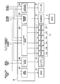
プリプレグ自動積層装置10は、積層ステージ11と、プリプレグ積層ヘッド13と、を有する。
積層ステージ11は、Y方向に延びている。積層ステージ11の上面11aは、平坦な面とされている。積層ステージ11の上面11aには、製造途中のプリプレグ積層体5が載置されている。プリプレグ積層体5の上面5aは、プリプレグ積層体5の最上層を構成する他のプリプレグシート6の上面6aにより構成されている。
プリプレグ積層ヘッド13は、巻送部18と、支持ローラ19,23と、切断機構20と、ロータリダイカッター24(カッター部)と、クランプ部25と、ガイドローラ26,27と、スクレーパーローラ29と、巻取部31と、回転駆動部33と、コンパクタ35A~35Fと、コンパクタ昇降機構37と、制御装置38と、を有する。
巻送部18は、積層ステージ11の幅方向一方側で、かつ積層ステージ11の上方に設けられている。巻送部18は、回転軸回りに回転可能な円柱状の部材である。
巻送部18の外周面には、シート部材44が巻回されている。シート部材44は、剥離シート41の一面41aにプリプレグシート42が貼り付けられた構成とされている。剥離シート41は、巻送部18の外周面と対向する側に配置されている。
巻送部18は、シート部材44を支持ローラ19に向かう方向に送り出す。
巻送部18の外周面には、シート部材44が巻回されている。シート部材44は、剥離シート41の一面41aにプリプレグシート42が貼り付けられた構成とされている。剥離シート41は、巻送部18の外周面と対向する側に配置されている。
巻送部18は、シート部材44を支持ローラ19に向かう方向に送り出す。
支持ローラ19は、積層ステージ11の幅方向一方側に設けられている。支持ローラ19は、巻送部18から積層ステージ11の幅方向一方側に離れた位置に配置されている。支持ローラ19の外周面は、巻送部18から送り出されたシート部材44を構成する剥離シート41の他面41bと接触している。
支持ローラ19は、円柱状とされており、回転軸回りに回転可能な構成とされている。支持ローラ19は、巻送部18と支持ローラ19との間に位置するシート部材44が水平となるように支持している。
支持ローラ19は、円柱状とされており、回転軸回りに回転可能な構成とされている。支持ローラ19は、巻送部18と支持ローラ19との間に位置するシート部材44が水平となるように支持している。
切断機構20は、ベース板51と、切断部53と、昇降部55と、を有する。
ベース板51は、巻送部18と支持ローラ19との間に位置するシート部材44を水平支持可能な位置に設けられている。ベース板51は、シート部材44を構成する剥離シート41の他面41bと接触する上面51aを有する。ベース板51の位置は、図示していない支持部材に支持されることで規制されている。
ベース板51は、巻送部18と支持ローラ19との間に位置するシート部材44を水平支持可能な位置に設けられている。ベース板51は、シート部材44を構成する剥離シート41の他面41bと接触する上面51aを有する。ベース板51の位置は、図示していない支持部材に支持されることで規制されている。
切断部53は、ベース板51上に配置されたプリプレグシート42の上方に配置されている。
切断部53は、ローラ支持部57と、押さえローラ61~66(複数の押さえローラ)と、隙間68と、回転軸71~73と、カッター本体75と、を有する。
切断部53は、ローラ支持部57と、押さえローラ61~66(複数の押さえローラ)と、隙間68と、回転軸71~73と、カッター本体75と、を有する。
ローラ支持部57は、固定部57Aと、突出部57B,57Cと、を有する。
固定部57Aは、Z方向に延びており、昇降部55に固定されている。
突出部57Bは、固定部57Aの下部からシート部材44の送り方向に延びている。
突出部57Cは、固定部57Aの下部からシート部材44の送り方向に延びている。突出部57Cは、シート部材44の幅方向において、突出部57Bとの間に間隔を空けた状態で突出部57Bと対向している。
固定部57Aは、Z方向に延びており、昇降部55に固定されている。
突出部57Bは、固定部57Aの下部からシート部材44の送り方向に延びている。
突出部57Cは、固定部57Aの下部からシート部材44の送り方向に延びている。突出部57Cは、シート部材44の幅方向において、突出部57Bとの間に間隔を空けた状態で突出部57Bと対向している。
押さえローラ61~63(複数の押さえローラの一部)は、巻送部18から支持ローラ19に向かう方向に、押さえローラ61、押さえローラ62、押さえローラ63の順で配列されている。押さえローラ61~63は、シート部材44を搬送することが可能な向きで配置されている。押さえローラ61~63は、シート部材44の送り方向に延びる第1の列L1を構成している。
押さえローラ61~63は、突出部57Bと突出部57Cとの間に設けられている。押さえローラ61~63は、突出部57B側に配置されている。
押さえローラ61~63は、突出部57Bと突出部57Cとの間に設けられている。押さえローラ61~63は、突出部57B側に配置されている。
押さえローラ64~66(複数の押さえローラの残部)は、巻送部18から支持ローラ19に向かう方向に、押さえローラ64、押さえローラ65、押さえローラ66の順で配列されている。押さえローラ64~66は、シート部材44を搬送することが可能な向きで配置されている。押さえローラ64~66は、シート部材44の送り方向に延びる第2の列L2を構成している。
押さえローラ64~66は、第1の列L1と突出部57Cとの間に設けられている。つまり、押さえローラ64~66は、突出部57C側に配置されている。
押さえローラ64~66は、第1の列L1と突出部57Cとの間に設けられている。つまり、押さえローラ64~66は、突出部57C側に配置されている。
上記構成とされた押さえローラ64~66は、切断部53が下降して、プリプレグシート42の一面42aに当接された状態において、搬送状態にあるプリプレグシート42を押圧する(図3参照)。
一方、押さえローラ64~66は、図3に示す状態から切断部53が上昇した際に、プリプレグシート42の一面42aの上方に離れる(図1参照)。
一方、押さえローラ64~66は、図3に示す状態から切断部53が上昇した際に、プリプレグシート42の一面42aの上方に離れる(図1参照)。
隙間68は、第1の列L1と第2の列L2との間に形成されている。隙間68は、シート部材44の送り方向に延びている。プリプレグシート42の幅方向における隙間68の大きさは、カッター本体75の先端部75Aを挿入可能な大きさとされている。
回転軸71は、プリプレグシート42の幅方向に延びており、押さえローラ61,64を貫通している。回転軸71は、一方の端部が突出部57Bに回転可能な状態で支持されており、他方の端部が突出部57Cに回転可能な状態で支持されている。
これにより、押さえローラ61,64が回転させられると、回転軸71も押さえローラ61,64とともに回転する。
これにより、押さえローラ61,64が回転させられると、回転軸71も押さえローラ61,64とともに回転する。
回転軸72は、プリプレグシート42の幅方向に延びており、押さえローラ62,65を貫通している。回転軸72は、一方の端部が突出部57Bに回転可能な状態で支持されており、他方の端部が突出部57Cに回転可能な状態で支持されている。
これにより、押さえローラ62,65が回転させられると、回転軸72も押さえローラ62,65とともに回転する。
これにより、押さえローラ62,65が回転させられると、回転軸72も押さえローラ62,65とともに回転する。
回転軸73は、プリプレグシート42の幅方向に延びており、押さえローラ63,66を貫通している。回転軸73は、一方の端部が突出部57Bに回転可能な状態で支持されており、他方の端部が突出部57Cに回転可能な状態で支持されている。
これにより、押さえローラ63,66が回転させられると、回転軸73も押さえローラ63,66とともに回転する。
これにより、押さえローラ63,66が回転させられると、回転軸73も押さえローラ63,66とともに回転する。
カッター本体75は、シート部材44の送り方向にプリプレグシート42を切断するためのものである。カッター本体75は、Z方向に延びており、プリプレグシート42の幅方向の中央に配置されている。
カッター本体75の先端部75Aは、隙間68に挿入されている。先端部75Aの先端75AAは、プリプレグシート42を切断するため、押さえローラ61~66よりも下方に突出している。
押さえローラ61~66の下端を基準としたときの先端75AAの突出量は、プリプレグシート42の厚さ、及び剥離シート41の厚さを考慮して適宜設定することが可能である。
具体的には、先端75AAの突出量は、プリプレグシート42を厚さ方向に分断可能で、かつ剥離シート41を分断しない大きさ(剥離シート41の厚さ方向の一部のみを切断可能な大きさ)とされている。
具体的には、先端75AAの突出量は、プリプレグシート42を厚さ方向に分断可能で、かつ剥離シート41を分断しない大きさ(剥離シート41の厚さ方向の一部のみを切断可能な大きさ)とされている。
上記構成とされたカッター本体75は、送り方向に移動するプリプレグシート42に当接されることで、プリプレグシート42のうち、プリプレグ切出部42Aに対応する部分の中央部に位置する切断位置C1を切断する。
プリプレグ切出部42Aは、他のプリプレグシート6の上面6aに積層されるプリプレグ切断部42Bと、不要な部分である不要部分42Cと、が一体に構成された構造とされている。
プリプレグ切出部42Aは、他のプリプレグシート6の上面6aに積層されるプリプレグ切断部42Bと、不要な部分である不要部分42Cと、が一体に構成された構造とされている。
カッター本体75としては、例えば、超音波カッターを用いることが可能である。
このように、カッター本体75として、超音波カッターを用いることで、精度良くプリプレグシート42を切断することができる。
例えば、剥離シートの厚さが0.07mm、プリプレグシート42の厚さが0.19mm、カッター本体75が超音波カッターの場合、シート部材44内に挿入されるカッター本体75の先端部75Aの深さD1は、例えば、0.25mmとすることが可能である。
この場合、カッター本体75の先端の長さM1は、例えば、0.25mm以上とすることが可能である。
このように、カッター本体75として、超音波カッターを用いることで、精度良くプリプレグシート42を切断することができる。
例えば、剥離シートの厚さが0.07mm、プリプレグシート42の厚さが0.19mm、カッター本体75が超音波カッターの場合、シート部材44内に挿入されるカッター本体75の先端部75Aの深さD1は、例えば、0.25mmとすることが可能である。
この場合、カッター本体75の先端の長さM1は、例えば、0.25mm以上とすることが可能である。
昇降部55は、切断部53の上方に設けられており、切断部53と接続されている。昇降部55は、シート部材44に対して切断部53を昇降させる。
支持ローラ23は、積層ステージ11の幅方向一方側に設けられている。支持ローラ23は、支持ローラ19の位置よりも下方で、かつX方向において支持ローラ19よりも積層ステージ11から離れた位置に配置されている。
支持ローラ23は、円柱状とされており、回転軸回りに回転可能な構成とされている。支持ローラ23の外周面は、支持ローラ19を経由したシート部材44を構成する剥離シート41の他面41bと接触している。
支持ローラ23は、支持ローラ19を経由したシート部材44が他のプリプレグシート6の上面6a側に向かうように、シート部材44を支持している。
支持ローラ23は、支持ローラ19を経由したシート部材44が他のプリプレグシート6の上面6a側に向かうように、シート部材44を支持している。
ロータリダイカッター24は、支持ローラ19と支持ローラ23との間に設けられている。ロータリダイカッター24は、支持ローラ19と支持ローラ23との間に配置されたシート部材44を構成するプリプレグシート42の幅方向を切断する。
ロータリダイカッター24は、切断位置C1が切断されたプリプレグ切出部42Aを切り出すための切断位置C2,C3を切断することで、互いに分離されたプリプレグ切断部42Bと不要部分42Cとを形成する。
プリプレグ切断部42B及び不要部分42Cは、剥離シート41に貼り付けられた状態で、ロータリダイカッター24の後段に配置された支持ローラ23に搬送される。
プリプレグ切断部42B及び不要部分42Cは、剥離シート41に貼り付けられた状態で、ロータリダイカッター24の後段に配置された支持ローラ23に搬送される。
なお、切断機構20を有していない場合、ロータリダイカッター24は、プリプレグ切断部42B及び不要部分42Cが一体とされたプリプレグ切出部42Aを切り出す。
クランプ部25は、支持ローラ19とロータリダイカッター24との間に配置されている。クランプ部25は、支持ローラ19とロータリダイカッター24との間に位置するシート部材44をクランプすることで、シート部材44の位置を規制する。
ガイドローラ26は、積層ステージ11の幅方向一方側に設けられている。ガイドローラ26は、支持ローラ23よりも低い位置で、かつ支持ローラ23よりも積層ステージ11に近い位置に配置されている。
ガイドローラ26は、円柱形状とされており、回転軸回りに回転可能な構成とされている。ガイドローラ26の外周面は、シート部材44を構成する剥離シート41の他面41bと接触している。ガイドローラ26は、プリプレグシート42を他のプリプレグシート6の上面6aに案内する。
ガイドローラ26は、円柱形状とされており、回転軸回りに回転可能な構成とされている。ガイドローラ26の外周面は、シート部材44を構成する剥離シート41の他面41bと接触している。ガイドローラ26は、プリプレグシート42を他のプリプレグシート6の上面6aに案内する。
ガイドローラ27は、積層ステージ11の幅方向他方側に設けられている。ガイドローラ27は、円柱形状とされており、回転軸回りに回転可能な構成とされている。ガイドローラ27の外周面は、剥離シート41の他面41bと接触している。ガイドローラ27は、巻取部31に向かう方向に剥離シート41を案内する。
スクレーパーローラ29は、積層ステージ11の幅方向他方側に設けられている。スクレーパーローラ29は、ガイドローラ27と積層ステージ11との間に設けられている。
スクレーパーローラ29は、円柱形状とされており、回転軸回りに回転可能な構成とされている。スクレーパーローラ29の外周面は、剥離シート41の一面41aと接触している。スクレーパーローラ29は、プリプレグシート42から剥離シート41を剥がす。
スクレーパーローラ29は、円柱形状とされており、回転軸回りに回転可能な構成とされている。スクレーパーローラ29の外周面は、剥離シート41の一面41aと接触している。スクレーパーローラ29は、プリプレグシート42から剥離シート41を剥がす。
巻取部31は、ガイドローラ27よりも上方の位置で、かつ積層ステージ11までの距離がガイドローラ27よりも離れた位置に配置されている。
巻取部31は、円柱形状とされており、回転軸回りに回転可能な構成とされている。巻取部31の外周面は、剥離シート41の他面41bと接触している。巻取部31は、回転させられた際、剥離シート41を巻き取る。
巻取部31は、円柱形状とされており、回転軸回りに回転可能な構成とされている。巻取部31の外周面は、剥離シート41の他面41bと接触している。巻取部31は、回転させられた際、剥離シート41を巻き取る。
回転駆動部33は、巻取部31を回転させるための駆動部である。回転駆動部33により、巻取部31が回転させられると、剥離シート41が巻き取られる。巻取部31の回転が停止されると、剥離シート41の巻き取りが停止される。
コンパクタ35A~35Fは、プリプレグ切断部42Bから不要部分42Cに向かうY方向において、コンパクタ35A、コンパクタ35B、コンパクタ35C、コンパクタ35D、コンパクタ35E、コンパクタ35Fの順で互いに隣り合うように配置されている。
コンパクタ35A~35Fは、積層ステージ11の上方に位置するシート部材44の上方に配置されている。コンパクタ35A~35Fは、それぞれ他のコンパクタ(コンパクタ35A~35Fのうちの4つのコンパクタ)とは独立した構成とされている。これにより、各コンパクタ35A~35Fは、他のコンパクタとは独立して、昇降可能な構成とされている。
コンパクタ35A~35Fは、コンパクタ35A~35Fの下部を構成するとともに、上方から下方に向かう方向に突出する円弧状の凸部81Aを有する。
凸部81Aが剥離シート41を押圧することで、剥離シート41を介して、プリプレグ切断部42Bのみを押圧する。
プリプレグ切断部42Bを押圧する際、コンパクタ35A~35Fは、G方向に一体的に移動する。
凸部81Aが剥離シート41を押圧することで、剥離シート41を介して、プリプレグ切断部42Bのみを押圧する。
プリプレグ切断部42Bを押圧する際、コンパクタ35A~35Fは、G方向に一体的に移動する。
なお、プリプレグ自動積層装置10は、積層ステージ11または他のプリプレグシート6が延びる方向に対するプリプレグ積層ヘッド13の向き(シート部材44を供給する方向)を変えるヘッド向き調整機構(図示せず)を有する。
ヘッド向き調整機構は、プリプレグ積層ヘッド13の向きを変更した際、シート部材44の供給方向と反対の方向を向くようにコンパクタ35A~35Fの向きを変える。
ヘッド向き調整機構は、プリプレグ積層ヘッド13の向きを変更した際、シート部材44の供給方向と反対の方向を向くようにコンパクタ35A~35Fの向きを変える。
コンパクタ昇降機構37は、昇降部37A~37Fを有する。
昇降部37Aは、コンパクタ35Aの上方に設けられており、コンパクタ35Aと接続されている。昇降部37Aは、コンパクタ35Aのみを昇降させる。
昇降部37Bは、コンパクタ35Bの上方に設けられており、コンパクタ35Bと接続されている。昇降部37Bは、コンパクタ35Bのみを昇降させる。
昇降部37Aは、コンパクタ35Aの上方に設けられており、コンパクタ35Aと接続されている。昇降部37Aは、コンパクタ35Aのみを昇降させる。
昇降部37Bは、コンパクタ35Bの上方に設けられており、コンパクタ35Bと接続されている。昇降部37Bは、コンパクタ35Bのみを昇降させる。
昇降部37Cは、コンパクタ35Cの上方に設けられており、コンパクタ35Cと接続されている。昇降部37Cは、コンパクタ35Cのみを昇降させる。
昇降部37Dは、コンパクタ35Dの上方に設けられており、コンパクタ35Dと接続されている。昇降部37Dは、コンパクタ35Dのみを昇降させる。
昇降部37Dは、コンパクタ35Dの上方に設けられており、コンパクタ35Dと接続されている。昇降部37Dは、コンパクタ35Dのみを昇降させる。
昇降部37Eは、コンパクタ35Eの上方に設けられており、コンパクタ35Eと接続されている。昇降部37Eは、コンパクタ35Eのみを昇降させる。
昇降部37Fは、コンパクタ35Fの上方に設けられており、コンパクタ35Fと接続されている。昇降部37Fは、コンパクタ35Fのみを昇降させる。
昇降部37Fは、コンパクタ35Fの上方に設けられており、コンパクタ35Fと接続されている。昇降部37Fは、コンパクタ35Fのみを昇降させる。
制御装置38は、昇降制御部38Aと、カッター制御部38Bと、クランプ開閉制御部38Cと、回転駆動制御部38Dと、コンパクタ昇降制御部38Eと、を有する。
昇降制御部38Aは、昇降部55と電気的に接続されている。
昇降制御部38Aは、プリプレグ切出部42A及びプリプレグ切断部42Bの形状に関する情報が入力され、巻き送り方向切断指令信号を受信すると、昇降部55を制御することで、切断部53を下降させる。
このとき、押さえローラ61~66によりプリプレグ切出部42Aを押圧することが可能な位置で、かつカッター本体75がプリプレグシート42を分断可能な位置まで切断部53を下降させる。
昇降制御部38Aは、プリプレグ切出部42A及びプリプレグ切断部42Bの形状に関する情報が入力され、巻き送り方向切断指令信号を受信すると、昇降部55を制御することで、切断部53を下降させる。
このとき、押さえローラ61~66によりプリプレグ切出部42Aを押圧することが可能な位置で、かつカッター本体75がプリプレグシート42を分断可能な位置まで切断部53を下降させる。
そして、押さえローラ61~66によりプリプレグ切出部42Aを押圧させた状態で、カッター本体75によりプリプレグ切出部42Aの切断位置C1を切断する。
その後、昇降制御部38Aは、切断部53を上昇させることで、押さえローラ61~66及びカッター本体75をプリプレグシート42から離間させる。
その後、昇降制御部38Aは、切断部53を上昇させることで、押さえローラ61~66及びカッター本体75をプリプレグシート42から離間させる。
カッター制御部38Bは、ロータリダイカッター24と電気的に接続されている。カッター制御部38Bは、プリプレグ切出部42A及びプリプレグ切断部42Bの形状に関する情報が入力され、幅方向切断指令信号を受信すると、ロータリダイカッター24を用いて、切断位置C2,C3に対応するプリプレグシート42を切断する。
これにより、プリプレグ切断部42Bと、不要部分42Cと、が切り出される。
これにより、プリプレグ切断部42Bと、不要部分42Cと、が切り出される。
クランプ開閉制御部38Cは、クランプ部25と電気的に接続されている。クランプ開閉制御部38Cは、押圧開始指令信号(プリプレグ切断部42Bの押圧を開始させる信号)が入力されると、クランプ部25にシート部材44をクランプさせて、シート部材44の位置を規制する。
また、クランプ開閉制御部38Cは、押圧終了指令信号(プリプレグ切断部42Bの押圧を終了させる信号)が入力された際、クランプ部25によるシート部材44のクランプを解除する。
回転駆動制御部38Dは、回転駆動部33と電気的に接続されている。回転駆動制御部38Dは、押圧開始指令信号が入力された際、回転駆動部33を制御することで、巻取部31の回転を停止させる。
また、回転駆動制御部38Dは、押圧終了指令信号が入力された際、回転駆動部33を制御することで、巻取部31の回転を再開させる。
また、回転駆動制御部38Dは、押圧終了指令信号が入力された際、回転駆動部33を制御することで、巻取部31の回転を再開させる。
コンパクタ昇降制御部38Eは、各昇降部37A~37Fと電気的に接続されている。コンパクタ昇降制御部38Eは、各昇降部37A~37Fを独立して制御する。
コンパクタ昇降制御部38Eには、プリプレグ切断部42Bの様々な形状に対応する駆動プログラムに基づいて、各昇降部37A~37Fを制御する。
上記駆動プログラムには、初期状態における各コンパクタ35A~35Fの高さ方向の位置に関する情報や、移動速度等の情報が含まれている。
コンパクタ昇降制御部38Eには、プリプレグ切断部42Bの様々な形状に対応する駆動プログラムに基づいて、各昇降部37A~37Fを制御する。
上記駆動プログラムには、初期状態における各コンパクタ35A~35Fの高さ方向の位置に関する情報や、移動速度等の情報が含まれている。
プリプレグ切断部42Bの形状に関する情報がコンパクタ昇降制御部38Eに入力されると、コンパクタ昇降制御部38Eは、プリプレグ切断部42Bの押圧開始から押圧終了までの期間、各昇降部37A~37Fにより各コンパクタ35A~35Fの昇降を制御する。
ここで、図5及び図6を参照して、平行四辺形とされ、かつプリプレグシート42の幅の半分の幅とされたプリプレグ切断部42Bを押圧する場合を例に挙げて、制御装置38が行うプリプレグ切断部42Bの押圧処理について説明する。
初めに、制御装置38が押圧開始指令信号を受信すると、クランプ開閉制御部38Cによりシート部材44がクランプされるとともに、回転駆動制御部38Dにより巻取部31の回転を停止させる。これにより、シート部材44にかかるテンションは、シート部材44が巻き取りされている場合のテンションよりも小さくなる。
このように、プリプレグ切断部42Bの押圧を開始するまえに、シート部材44にかかるテンションを小さくすることで、コンパクタ35A~35Fのうち、一部のコンパクタのみでプリプレグ切断部42Bを押圧する際に、シート部材44に発生するせん断力を小さくすることが可能となる。これにより、シート部材44の破損を抑制することができる。
次いで、コンパクタ昇降制御部38Eは、押圧開始位置(幅方向他方側に位置するプリプレグ切断部42Bの端)において、昇降部37A~37Cによりプリプレグ切断部42Bの上方に位置するコンパクタ35A~35Cが剥離シート41を押圧可能な位置までコンパクタ35A~35Cを下降させるともに、不要部分42Cの上方に位置するコンパクタ35D~35Fが不要部分42Cの上方に位置する剥離シート41から離間する位置までコンパクタ35D~35Fを上昇させる。
その後、コンパクタ35A~35Fの高さ方向の位置を保ったままコンパクタ35A~35FをG方向に移動させることで、プリプレグ切断部42Bのみを押圧させる。これにより、プリプレグ切断部42Bの押圧処理が完了する。
このように、不要部分42Cを押圧させることなく、プリプレグ切断部42Bのみを押圧させることで、不要部分42Cが押圧されることに起因するプリプレグシート42の剥離(剥離シート41からのプリプレグシート42の剥離)を抑制することができる。
本実施形態のプリプレグ自動積層装置10によれば、プリプレグシート42を幅方向にのみ切断するロータリダイカッター24(カッター部)と、積層ステージ11の前段に設けられ、プリプレグシート42の送り方向にプリプレグシート42を切断することで、プリプレグ切断部42Bに対応する部分と不要部分42Cに対応する部分とを分離させる切断機構20と、切断機構20を制御する制御装置38と、を有することで、プリプレグシート42の幅よりも狭い幅とされたプリプレグ切断部42Bを自動で切り出すことが可能となる。
これにより、作業者がカッターでプリプレグ切断部42Bと不要部分42Cとの間を切断する場合と比較して、プリプレグシート42の幅よりも狭い幅とされたプリプレグ切断部42Bを容易かつ短時間で切り出すことができる。
これにより、作業者がカッターでプリプレグ切断部42Bと不要部分42Cとの間を切断する場合と比較して、プリプレグシート42の幅よりも狭い幅とされたプリプレグ切断部42Bを容易かつ短時間で切り出すことができる。
また、剥離シート41の他面41bと接触する上面51aを有するベース板51と、ベース板51上に配置されたプリプレグシート42に当接される押さえローラ61~66と、押さえローラ61~66に押圧された領域をプリプレグ切断部42Bに対応する部分と不要部分42Cに対応する部分とを分離させるカッター本体75と、切断部53をプリプレグシート42に対して昇降させる昇降部55と、を切断機構20が備えることで、押さえローラ61~66により押圧されたプリプレグシート42をカッター本体75が切断することになるため、カッター本体75が切断する切断位置C1の位置精度を向上させることができる。
また、押さえローラ61~66とカッター本体75とを一体に構成することで、カッター本体75により剥離シート41が切断されないように、押さえローラ61~66の下端から飛び出すカッター本体75の先端75AAの飛び出し量を一定にすることが可能となる。これにより、剥離シート41が分断されることを抑制した上で、安定してプリプレグシート42のみを分断することができる。
また、押さえローラ61~63で構成された第1の列L1と押さえローラ64~66で構成された第2の列L2との間に形成された隙間68に、カッター本体75の先端部75Aを挿入して配置させることで、カッター本体75を用いて、第1の列L1により押圧されたプリプレグ切断部42Bと第2の列L2により押圧されたプリプレグ切断部42Bとの間に位置するプリプレグシート42を切断することができる。
また、切断機構20を用いてプリプレグ切断部42Bを切断する際、制御装置38を用いて、剥離シート41を介してプリプレグ切断部42Bに押さえローラ61~66が当接されるとともに、カッター本体75の先端75AAがプリプレグシート42よりも下方でかつ剥離シート41を分断しない位置に配置されるように昇降部55を制御することで、剥離シート41が分断されることなく、プリプレグシート42のみを安定して切断することができる。
以上、本発明の好ましい実施形態について詳述したが、本発明はかかる特定の実施形態に限定されるものではなく、特許請求の範囲内に記載された本発明の要旨の範囲内において、種々の変形・変更が可能である。
本発明は、プリプレグ自動積層装置に適用可能である。
5 プリプレグ積層体
5a,6a,11a,51a 上面
6 他のプリプレグシート
10 プリプレグ自動積層装置
11 積層ステージ
13 プリプレグ積層ヘッド
18 巻送部
19,23 支持ローラ
20 切断機構
24 ロータリダイカッター
25 クランプ部
26,27 ガイドローラ
29 スクレーパーローラ
31 巻取部
33 回転駆動部
35A~35F コンパクタ
37 コンパクタ昇降機構
37A~37F 昇降部
38 制御装置
38A 昇降制御部
38B カッター制御部
38C クランプ開閉制御部
38D 回転駆動制御部
38E コンパクタ昇降制御部
41 剥離シート
41a,42a 一面
41b 他面
42 プリプレグシート
42A プリプレグ切出部
42B プリプレグ切断部
42C 不要部分
44 シート部材
51 ベース板
53 切断部
55 昇降部
57 ローラ支持部
57A 固定部
57B,57C 突出部
61~63 押さえローラ
68 隙間
75 カッター本体
75A 先端部
75AA 先端
81A 凸部
C1~C3 切断位置
D1 深さ
G 方向
L1 第1の列
L2 第2の列
M1 長さ
5a,6a,11a,51a 上面
6 他のプリプレグシート
10 プリプレグ自動積層装置
11 積層ステージ
13 プリプレグ積層ヘッド
18 巻送部
19,23 支持ローラ
20 切断機構
24 ロータリダイカッター
25 クランプ部
26,27 ガイドローラ
29 スクレーパーローラ
31 巻取部
33 回転駆動部
35A~35F コンパクタ
37 コンパクタ昇降機構
37A~37F 昇降部
38 制御装置
38A 昇降制御部
38B カッター制御部
38C クランプ開閉制御部
38D 回転駆動制御部
38E コンパクタ昇降制御部
41 剥離シート
41a,42a 一面
41b 他面
42 プリプレグシート
42A プリプレグ切出部
42B プリプレグ切断部
42C 不要部分
44 シート部材
51 ベース板
53 切断部
55 昇降部
57 ローラ支持部
57A 固定部
57B,57C 突出部
61~63 押さえローラ
68 隙間
75 カッター本体
75A 先端部
75AA 先端
81A 凸部
C1~C3 切断位置
D1 深さ
G 方向
L1 第1の列
L2 第2の列
M1 長さ
Claims (5)
- 一方向に延びる積層ステージと、
前記積層ステージ上または前記積層ステージ上に配置された他のプリプレグシート上に、剥離シートの一面に貼り付けられたプリプレグシートを送る巻送部、前記巻送部の下流側で、かつ前記積層ステージの前段に設けられ、前記プリプレグシートを幅方向にのみ切断することで、プリプレグ切断部及び不要部分が一体とされたプリプレグ切出部を切り出すカッター部、前記プリプレグシートから剥離された剥離シートを巻き取る巻取部、及び前記一方向に配置され、前記巻取部側から前記巻送部側に向かう方向に移動することで、前記剥離シートを介して前記プリプレグ切断部を押圧する複数のコンパクタを含むプリプレグ積層ヘッドと、
を備え、
前記プリプレグ積層ヘッドは、前記積層ステージの前段に設けられ、前記プリプレグシートの送り方向に前記プリプレグシートを切断することで、前記プリプレグ切断部に対応する部分と前記不要部分に対応する部分とを分離させる切断機構と、
前記切断機構を制御する制御装置と、
を有するプリプレグ自動積層装置。 - 前記切断機構は、前記巻送部と前記カッター部との間に配置され、前記剥離シートの他面と接触する上面を有するベース板と、
前記ベース板の上方に配置され、前記ベース板上に配置された前記プリプレグシートに当接される複数の押さえローラ、及び前記複数の押さえローラに押圧された領域を前記プリプレグシートの送り方向に切断することで、前記プリプレグシートの幅方向において前記プリプレグ切断部に対応する部分と前記不要部分に対応する部分とを分離させるカッター本体が一体とされた切断部と、
前記制御装置と電気的に接続され、前記切断部を前記プリプレグシートに対して昇降させる昇降部と、
を有する請求項1記載のプリプレグ自動積層装置。 - 前記複数の押さえローラのうち、一部の前記押さえローラは、前記プリプレグシートの送り方向に配置されて第1の列を構成しており、残部の前記押さえローラは、前記プリプレグシートの幅方向において前記第1の列を構成する押さえローラと互いに隣り合うように配置されて第2の列を構成しており、
前記第1の列と前記第2の列との間には、隙間が形成されており、
前記カッター本体の先端部は、前記隙間に挿入されて配置されている請求項2記載のプリプレグ自動積層装置。 - 前記制御装置は、前記切断機構を用いて前記プリプレグシートを切断する際、前記複数の押さえローラが前記プリプレグシートに当接されるとともに、前記カッター本体の先端が前記プリプレグシートよりも下方でかつ前記剥離シートを分断しない位置に配置されるように前記昇降部を制御する請求項2または3記載のプリプレグ自動積層装置。
- 前記カッター本体は、超音波カッターである請求項2から4のうち、いずれか一項記載のプリプレグ自動積層装置。
Priority Applications (1)
| Application Number | Priority Date | Filing Date | Title |
|---|---|---|---|
| US17/260,282 US11396147B2 (en) | 2018-10-24 | 2019-08-14 | Prepreg automatic layering device |
Applications Claiming Priority (2)
| Application Number | Priority Date | Filing Date | Title |
|---|---|---|---|
| JP2018200319A JP2020066168A (ja) | 2018-10-24 | 2018-10-24 | プリプレグ自動積層装置 |
| JP2018-200319 | 2018-10-24 |
Publications (1)
| Publication Number | Publication Date |
|---|---|
| WO2020084875A1 true WO2020084875A1 (ja) | 2020-04-30 |
Family
ID=70331517
Family Applications (1)
| Application Number | Title | Priority Date | Filing Date |
|---|---|---|---|
| PCT/JP2019/031948 Ceased WO2020084875A1 (ja) | 2018-10-24 | 2019-08-14 | プリプレグ自動積層装置 |
Country Status (3)
| Country | Link |
|---|---|
| US (1) | US11396147B2 (ja) |
| JP (1) | JP2020066168A (ja) |
| WO (1) | WO2020084875A1 (ja) |
Families Citing this family (1)
| Publication number | Priority date | Publication date | Assignee | Title |
|---|---|---|---|---|
| DE102019203383A1 (de) * | 2019-03-13 | 2020-09-17 | Zf Friedrichshafen Ag | Verfahren und System zum Erzeugen eines Faservorformlings |
Citations (5)
| Publication number | Priority date | Publication date | Assignee | Title |
|---|---|---|---|---|
| JP2003191197A (ja) * | 2001-12-25 | 2003-07-08 | Matsushita Electric Works Ltd | プリプレグの切断方法 |
| JP2004181683A (ja) * | 2002-11-29 | 2004-07-02 | Kawasaki Heavy Ind Ltd | プリプレグ幅変更自動積層方法及びその装置 |
| JP2010023449A (ja) * | 2008-07-24 | 2010-02-04 | Toray Ind Inc | 繊維強化プラスチックの製造方法 |
| JP2011177927A (ja) * | 2010-02-26 | 2011-09-15 | Mitsubishi Heavy Ind Ltd | プリプレグ積層ヘッド及びこれを備えたプリプレグ自動積層装置 |
| JP2015140428A (ja) * | 2014-01-30 | 2015-08-03 | 三菱重工業株式会社 | プリプレグ自動積層装置 |
Family Cites Families (1)
| Publication number | Priority date | Publication date | Assignee | Title |
|---|---|---|---|---|
| JP6313115B2 (ja) * | 2014-05-14 | 2018-04-18 | 津田駒工業株式会社 | 自動積層装置における積層位置の補正方法 |
-
2018
- 2018-10-24 JP JP2018200319A patent/JP2020066168A/ja not_active Withdrawn
-
2019
- 2019-08-14 US US17/260,282 patent/US11396147B2/en active Active
- 2019-08-14 WO PCT/JP2019/031948 patent/WO2020084875A1/ja not_active Ceased
Patent Citations (5)
| Publication number | Priority date | Publication date | Assignee | Title |
|---|---|---|---|---|
| JP2003191197A (ja) * | 2001-12-25 | 2003-07-08 | Matsushita Electric Works Ltd | プリプレグの切断方法 |
| JP2004181683A (ja) * | 2002-11-29 | 2004-07-02 | Kawasaki Heavy Ind Ltd | プリプレグ幅変更自動積層方法及びその装置 |
| JP2010023449A (ja) * | 2008-07-24 | 2010-02-04 | Toray Ind Inc | 繊維強化プラスチックの製造方法 |
| JP2011177927A (ja) * | 2010-02-26 | 2011-09-15 | Mitsubishi Heavy Ind Ltd | プリプレグ積層ヘッド及びこれを備えたプリプレグ自動積層装置 |
| JP2015140428A (ja) * | 2014-01-30 | 2015-08-03 | 三菱重工業株式会社 | プリプレグ自動積層装置 |
Also Published As
| Publication number | Publication date |
|---|---|
| JP2020066168A (ja) | 2020-04-30 |
| US11396147B2 (en) | 2022-07-26 |
| US20210299983A1 (en) | 2021-09-30 |
Similar Documents
| Publication | Publication Date | Title |
|---|---|---|
| JP5439225B2 (ja) | プリプレグ積層ヘッド及びこれを備えたプリプレグ自動積層装置 | |
| JP6712900B2 (ja) | 強化繊維基材の製造方法 | |
| JP5518639B2 (ja) | 変圧器鉄心の製造装置および製造方法 | |
| EP2540478A1 (en) | Prepreg lamination head and automatic prepreg lamination device equipped with same | |
| US7665499B2 (en) | Laminating apparatus for ceramic green sheet and laminating method for same | |
| JP5961105B2 (ja) | 積層装置および積層体形成方法 | |
| US9956705B2 (en) | Compactor and prepreg sheet automatic lamination device | |
| WO2020090218A1 (ja) | プリプレグ自動積層装置 | |
| JP2020066168A (ja) | プリプレグ自動積層装置 | |
| US20060219070A1 (en) | Cutting apparatus for ceramic green sheet and cutting method for same | |
| WO2019107475A1 (ja) | シート供給装置及びシート供給方法 | |
| US11524469B2 (en) | Composite material automatic laminating device | |
| JP2015140428A (ja) | プリプレグ自動積層装置 | |
| JP5890439B2 (ja) | 切断装置及び絶縁スペーサの生産方法 | |
| CN104210123B (zh) | 裁断机 | |
| JP5330139B2 (ja) | タイヤ材料のジョイント装置およびタイヤ材料の作製方法 | |
| JP4576268B2 (ja) | テープ貼込装置 | |
| WO2019107473A1 (ja) | シート供給装置及びシート供給方法 | |
| CN118829600A (zh) | 胶带贴合装置 | |
| JP6537219B2 (ja) | ヒンジを有する本 | |
| KR101205215B1 (ko) | 보호필름 컷팅 장치 | |
| JP5703465B2 (ja) | 製本装置 | |
| CN115052823A (zh) | 带层压机切割组件 | |
| KR20230047841A (ko) | 무기재테이프 형상가공장치 | |
| JP2573733Y2 (ja) | 基板分割装置 |
Legal Events
| Date | Code | Title | Description |
|---|---|---|---|
| 121 | Ep: the epo has been informed by wipo that ep was designated in this application |
Ref document number: 19877391 Country of ref document: EP Kind code of ref document: A1 |
|
| NENP | Non-entry into the national phase |
Ref country code: DE |
|
| 122 | Ep: pct application non-entry in european phase |
Ref document number: 19877391 Country of ref document: EP Kind code of ref document: A1 |