WO2020084705A1 - Dispositif d'analyse de polymère biologique, analyseur l'utilisant et procédé d'analyse - Google Patents
Dispositif d'analyse de polymère biologique, analyseur l'utilisant et procédé d'analyse Download PDFInfo
- Publication number
- WO2020084705A1 WO2020084705A1 PCT/JP2018/039466 JP2018039466W WO2020084705A1 WO 2020084705 A1 WO2020084705 A1 WO 2020084705A1 JP 2018039466 W JP2018039466 W JP 2018039466W WO 2020084705 A1 WO2020084705 A1 WO 2020084705A1
- Authority
- WO
- WIPO (PCT)
- Prior art keywords
- biopolymer
- nanopore
- dna
- enzyme
- dna polymerase
- Prior art date
Links
Images


Classifications
-
- C—CHEMISTRY; METALLURGY
- C12—BIOCHEMISTRY; BEER; SPIRITS; WINE; VINEGAR; MICROBIOLOGY; ENZYMOLOGY; MUTATION OR GENETIC ENGINEERING
- C12M—APPARATUS FOR ENZYMOLOGY OR MICROBIOLOGY; APPARATUS FOR CULTURING MICROORGANISMS FOR PRODUCING BIOMASS, FOR GROWING CELLS OR FOR OBTAINING FERMENTATION OR METABOLIC PRODUCTS, i.e. BIOREACTORS OR FERMENTERS
- C12M1/00—Apparatus for enzymology or microbiology
Definitions
- the present disclosure relates to a biopolymer analysis device, an analysis device using the same, and an analysis method.
- An analyzer using a nanopore device has been developed as an analyzer for analyzing the monomer sequence of a biopolymer.
- Such an analyzer is used as a DNA base sequence analysis system (DNA sequencer) when the biopolymer is DNA, and as an amino acid sequence analysis system (amino acid sequencer) when the biopolymer is protein. It is expected as a system capable of decoding long sequence lengths.
- a nanopore device is a thin film with pores (nanopores) with a diameter of several ⁇ to several nanometers and a liquid tank on each side of a thin film with a thickness of several ⁇ to several tens of nanometers.
- An electrolyte solution is passed through the nanopores by creating a potential difference across both ends of the nanopore.
- a pH neutral aqueous potassium chloride solution is typically used as the electrolyte solution.
- the ionic current around the nanopore changes in a pattern according to the monomer arrangement pattern.
- the ionic current is proportional to the cross-sectional area of the nanopore as a first approximation.
- the biopolymer blocks the nanopore and reduces the effective cross-sectional area through which the ions can pass, thus reducing the ionic current. This reduction amount is called a blocking current.
- Such a blocking current type nanopore device can analyze a monomer arrangement of a biopolymer by detecting a change in ionic current. Since the analysis accuracy of the monomer array is determined by the amount of change in ion current, the larger the difference in ion current amount between monomers, the better.
- nanopore devices There are two types of nanopore devices: a bio-nanopore type that uses a protein with a central pore that is embedded in a lipid bilayer, and a solid nanopore type that uses an insulating thin film formed by a semiconductor processing process.
- a bio-nanopore type that uses a protein with a central pore that is embedded in a lipid bilayer
- a solid nanopore type that uses an insulating thin film formed by a semiconductor processing process.
- the pores (diameter 1.2 nm, thickness 0.6 nm) of the modified protein (Mycobacterium smegmatisporinA (MspA) etc.) embedded in the lipid bilayer membrane are used as the biopolymer detector to detect ionic current. Measure the amount of change.
- MspA Mycobacterium smegmatisporinA
- the solid nanopore type a structure in which nanopores are formed in a thin film of silicon nitride (SiN) which is a semiconductor material or a thin film composed of a monomolecular layer such as graphene or molybdenum disulfide is used.
- SiN silicon nitride
- a monomolecular layer such as graphene or molybdenum disulfide
- Patent Document 1 As a solid nanopore type nanopore DNA sequencer, it has been reported that the blocking current amount of homopolymer adenine base, cytosine base, thymine base, and guanine base was measured using an aqueous potassium chloride solution under neutral pH (Patent Document 1).
- a DNA polymerase binds a primer to DNA serving as a template, passes a single-stranded portion through a nanopore, and an elongation reaction occurs when the DNA polymerase binds to a primer end, so that the DNA is pulled by an electric field.
- the delivery of DNA is realized against the force.
- an ion current signal corresponding to the base species can be obtained (Patent Documents 2 to 5).
- the problem with the above transport control method is that it is difficult to control the enzyme under high salt concentration.
- the electrical conductivity of the nanopores is higher under a high salt concentration, so that the fluctuation amount of the blockade current signal corresponding to the base sequence at the time of passing through the DNA is increased, while the noise signal is increased. Since it is almost constant, measurement can be realized with a high SN ratio (Signal / Noise ratio).
- the enzyme is inactivated and cannot function as a molecular motor, so that there is a trade-off problem that DNA transport cannot be controlled.
- a biopolymer analysis device that satisfactorily controls the transport of each monomer, an analysis apparatus using the same, and an analysis method are provided.
- a biopolymer analysis device includes a thin film having nanopores, a first liquid tank and a second liquid tank that are arranged so as to sandwich the thin film, and store an electrolyte solution, An external field applying unit for applying an external field between the first liquid tank and the second liquid tank, wherein the first liquid tank has a biological polymer, an enzyme that binds to the biological polymer, and the enzyme. Is introduced into the nanopore by the application of the external field, the enzyme takes up the NTP analog, and the biopolymer is transported in the nanopore. It is characterized by
- the schematic diagram which shows the conveyance control process of the biopolymer in the nanopore vicinity. The figure explaining the state of a living body polymer in the case where an extension reaction is started before introducing a nanopore of a living body polymer (a), and when an extension reaction is started after introducing a living body's nanopore (b).
- the figure which shows the structural formula of dNTP The figure which shows the result of the electrophoresis in the salt tolerance test of Bst 3.0 DNA polymerase. The figure which shows the result of the electrophoresis in the salt tolerance test of Csa DNA polymerase.
- 96-7 is a view showing a result of electrophoresis in a salt tolerance test of 96-7 DNA polymerase.
- phi29 is a diagram showing the results of electrophoresis in a salt tolerance test of DNA polymerase.
- the figure which shows the structural formula of NMP-PNP The figure which shows the result of the nanopore analysis when NMP-PNP is used as a substrate for Bst 3.0 DNA polymerase.
- FIG. 1 is a schematic diagram showing the configuration of an analyzer 1 according to the first embodiment.
- the analysis apparatus 1 includes a biopolymer analysis device 100, an ammeter 106, a power supply 107, and a computer 108 (analysis unit).
- the biological polymer to be analyzed is, for example, DNA or RNA whose nucleic acid is a monomer, or a polypeptide or protein whose amino acid is a monomer.
- the analyzer 1 is a DNA sequencer that analyzes DNA will be described as an example.
- the biopolymer analysis device 100 includes a thin film 102A having nanopores 101, liquid tanks 104A and 104B (first liquid tank and second liquid tank) containing an electrolyte solution 103, and electrodes 105A and 105B (external field application unit). Equipped with.
- the biopolymer analysis device 100 adopts a method of introducing the biopolymer 109 into the nanopore 101 by electrophoresis.
- the method of introducing the biopolymer 109 into the nanopore 101 is not limited to this, and other methods may be adopted.
- the thin film 102A may be a lipid bilayer (bio-type nanopore) composed of an amphipathic molecule layer in which a protein having a pore in the center is embedded, or a thin film (Material formed by semiconductor microfabrication technology ( It may be a solid type nanopore).
- Materials that can be formed by the semiconductor fine processing technology include, for example, silicon nitride (SiN), silicon oxide (SiO 2 ), silicon oxynitride (SiON), hafnium oxide (HfO 2 ), molybdenum disulfide (MoS 2 ), graphene, and the like. Is mentioned.
- the thickness of the thin film 102A is preferably 1 ⁇ to 200 nm, more preferably 1 ⁇ to 100 nm, still more preferably 1 ⁇ to 50 nm, and for example, about 5 nm.
- the depth of the nanopore 101 can be adjusted by adjusting the thickness of the thin film 102A.
- the depth of the nanopore 101 is preferably 2 times or more, more preferably 3 times or more, further preferably 5 times or more as large as the monomer unit constituting the biopolymer 109.
- the depth of the nanopore 101 is preferably, for example, 3 bases or more, that is, about 1 nm or more. This allows the biopolymer 109 to enter the nanopore 101 while controlling its shape and moving speed, and enables highly sensitive and highly accurate analysis.
- the shape of the cross section of the nanopore 101 in the horizontal plane is basically circular, but it may be elliptical or polygonal.
- the liquid tanks 104A and 104B are arranged on both sides of the thin film 102A and filled with the electrolyte solution 103. Electrode 105A is arranged in liquid tank 104A, and electrode 105B is arranged in liquid tank 104B.
- the liquid tanks 104A and 104B are formed of a material, shape and size that do not affect the measurement of the blocking current.
- the capacity of the electrolyte solution 103 is, for example, on the order of microliters or milliliters. Details of the electrolyte solution 103 will be described later.
- the biopolymer 109 is introduced into the liquid tank 104A during the nanopore analysis in a state of being bound to the control chain 111 by the pretreatment.
- the electrodes 105A and 105B are preferably made of a material capable of performing an electron transfer reaction (Faraday reaction) with the electrolyte in the electrolyte solution 103, and typically made of silver halide or alkali silver halide. To be done. From the viewpoint of potential stability and reliability, it is preferable to use silver or silver chloride.
- Faraday reaction electron transfer reaction
- the electrodes 105A and 105B may be made of a material that becomes a polarized electrode, for example, gold or platinum. In that case, in order to secure a stable ionic current, it is preferable to add a substance capable of assisting the electron transfer reaction to the electrolyte solution 103, such as potassium ferricyanide or potassium ferrocyanide. Alternatively, it is preferable to immobilize a substance capable of performing an electron transfer reaction, such as ferrocene, on the surface of the polarized electrode.
- the electrodes 105A and 105B may be entirely made of the above material, or the surface of a base material (copper, aluminum, etc.) may be coated with the above material.
- the shapes of the electrodes 105A and 105B are not particularly limited, but a shape that increases the surface area in contact with the electrolyte solution 103 is preferable.
- connection terminals electrically connected to the electrodes 105A and 105B are provided on the outer peripheral surface of the biopolymer analysis device 100, whereby the electrodes 105A and 105B are connected to the power source 107 and It is connected to the ammeter 106.
- the biopolymer 109 passes through the nanopore 101 while being coupled to the molecular motor 110. Since the molecular motor 110 is generally larger than the diameter of the nanopore 101, it cannot pass through the nanopore 101. In order to realize this limitation, the diameter of the nanopore 101 is in the range of 0.8 nm, which is the lower limit that allows single-stranded DNA to pass, and 3 nm, which is the upper limit that the enzyme that is the molecular motor 110 does not pass. Is preferred.
- the ammeter 106 measures an ionic current (blocking current) flowing between the electrodes 105A and 105B. Although not shown, it has an amplifier for amplifying a current flowing between the electrodes 105A and 105B, and an analog / digital converter. The ammeter 106 is connected to the computer 108, and the analog / digital converter outputs the current value of the detected ion current to the computer 108 as a digital signal.
- the computer 108 acquires the monomer arrangement information of the biopolymer based on the detected ionic current value. Further, the computer 108 records the current value and the acquired monomer arrangement information.
- the current value measured in the absence of the biopolymer 109 is used as a reference (pore current), and the current observed when the biopolymer 109 is sealed (nanopore).
- the blockage by the biopolymer 109 of 101) is measured, and the passage speed and state of the molecule are observed.
- the acquired current value returns to the pore current. It is possible to analyze the nanopore passage speed of the biopolymer 109 from this blocking time, and to analyze the characteristics of the biopolymer 109 from the blocking amount.
- the configuration may be such that the monomer arrangement information of the biopolymer 109 is acquired based on the optical signal. That is, a method may be used in which each monomer is labeled with a characteristic fluorescence wavelength, and the fluorescence signal is measured to determine each monomer sequence.
- the power supply 107, the ammeter 106, and the computer 108 are not separate members from the biological polymer analysis device 100, but the power supply 107, the ammeter 106, and the computer 108 are used as the biological polymer analysis device 100. It may be integrated with.
- the nanopore 101 is formed on the thin film 102A by, for example, electron beam irradiation by a transmission electron microscope or the like, or dielectric breakdown by voltage application.
- the nanopore 101 can be formed by applying a voltage, for example, by the following procedure.
- the Si 3 N 4 thin film is made hydrophilic by Ar / O 2 plasma (manufactured by Samco Co., Ltd.) under the conditions of 10 WW, 20 sccm, 20 Pa, and 45 sec.
- the thin film 102A is set on the biopolymer analysis device 100.
- the liquid tanks 104A and 104B are filled with the electrolyte solution 103, the electrodes 105A and 105B are introduced into the liquid tanks 104A and 104B, and a voltage is applied.
- the liquid tank 104B located on the lower side is called a cis tank
- the liquid tank 104A located on the upper side is called a trans tank.
- the voltage Vcis applied to the electrode on the cis tank side is set to 0 V
- the voltage Vtrans is applied to the electrode on the trans tank side.
- the voltage Vtrans is applied as a pulse voltage by, for example, a pulse generator (41501B SMU AND Pulse Generator Expander, manufactured by Agilent Technologies).
- the process of applying a voltage to form the nanopore 101 is controlled by, for example, a self-made program (Excel VBA, Visual Basic for Applications).
- the current value after applying the pulse voltage can be read by an ammeter 106 (4156B PRECISION SEMICONDUCTOR ANALYZER, manufactured by Agilent Technologies).
- the diameter of the nanopore 101 can be estimated from the ion current value.
- a current value condition (threshold current) is selected in accordance with the diameter of the nanopore 101 formed before the application of the pulse voltage, and the diameter of the nanopore 101 is successively increased to obtain the target diameter.
- the criteria for selecting the conditions are shown in Table 1.
- the n-th pulse voltage application time t n (where n> 2 is an integer) is determined by the following equation.
- the transport control of the biopolymer 109 in this embodiment will be described.
- the transport control of the biopolymer 109 is mainly performed by the molecular motor 110 using an enzyme.
- an enzyme capable of binding to the biopolymer 109 can be used without particular limitation.
- the biopolymer 109 is DNA
- DNA polymerase, DNA helicase, DNA exonuclease, DNA transposase and the like can be mentioned.
- the biological polymer 109 is RNA, RNA polymerase, RNA helicase, RNA exonuclease, RNA transposase and the like can be mentioned.
- the molecular motor 110 and the substrate are introduced into the liquid tank 104A during nanopore analysis by the analyzer 1.
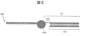
- control chain 111 is bonded to the biopolymer 109 that is the reading target.
- the target of the reading of the monomer sequence is a DNA chain which is a main chain of single-stranded or partially single-stranded DNA, and a control chain 111 in the main chain. It is included.
- the biopolymer 109 more preferably satisfies the following (a) to (c).
- the control chain 111 exists in the biopolymer 109 to be read.
- the primer 112 is bound to the control chain 111.
- the spacer 113 is present in the control chain 111.
- the primer 112 is a DNA sequence that is a complementary strand of the control strand 111.
- the spacer 113 has a role as a switch that controls the reaction of the molecular motor 110, and normally stops the reaction of the molecular motor 110. However, when the measurement is performed by the nanopore 101, that is, a force is applied to the molecule, It has a function of starting the reaction of the motor 110.
- the spacer 113 is preferably abasic, and is also preferably a linear linking body.
- the spacer arrangement length may be 1 base or more from the primer connecting portion, but it is preferably 2 bases or more, that is, about 0.6 ⁇ 2 nm or more.
- linkers examples include, but are not limited to, SpacerC3 (iSpC3), PC Spacer, Spacer9, Spacer18, dSpacer, hexanediol, linear carbon chain, linear chain.
- suitable linkers include, but are not limited to, SpacerC3 (iSpC3), PC Spacer, Spacer9, Spacer18, dSpacer, hexanediol, linear carbon chain, linear chain.
- suitable linkers include amino acids, straight chain fatty acids, straight chain sugar chains and the like. It is particularly preferable to introduce Spacer C3 continuously for 4 mer or more.
- the biopolymer 109 has a structure of a single-stranded protruding double-stranded DNA (ssDNA-overhang dsDNA) composed of a main-stranded DNA (template) to be read and a complementary-stranded DNA (primer) shorter than the main-stranded DNA. It is preferable to have
- FIG. 2 is a schematic diagram showing the configuration of the molecular complex according to the present embodiment.
- the molecular motor 110 binds to the single-stranded protruding double-stranded DNA in the vicinity of the boundary between the single-stranded portion and the double-stranded portion to form a molecular complex.
- the molecular motor 110 reacts with the primer 112 to move the relative positions of the main chain DNA and the nanopore 101 in the molecular complex described above by one base, thereby achieving good transport control. Done. This makes it possible to obtain the base sequence information in the main chain DNA.
- the biopolymer 109 is pulled up from the nanopore 101.
- the molecular motor 110 is a DNA helicase or a DNA exonuclease
- the biopolymer 109 is pulled down to the nanopore 101.
- FIG. 3 is a schematic diagram showing the transport control process of the biopolymer 109 in the vicinity of the nanopore 101.
- the biopolymer 109 is introduced into the electrolyte solution 103 in a state where the control chain 111 is bound.
- the molecular motor 110 and the substrate are dissolved in the electrolyte solution 103, and the biopolymer 109 and the molecular motor 110 are bound in the electrolyte solution 103.
- the biopolymer 109 bound to the molecular motor 110 is introduced into the nanopore 101 by the force 302 received from the electric field generated in the vicinity of the nanopore 101.
- the molecular motor 110 since the diameter of the molecular motor 110 is larger than the diameter of the nanopore 101, it cannot proceed toward the exit of the nanopore 101 and stays at the entrance of the nanopore 101.
- the biopolymer 109 having a negative charge further advances toward the exit of the nanopore 101 and undergoes a shape change around the spacer 113.
- the molecular motor 110 binds to the end of the primer 112 in the control chain 111 and starts an extension reaction.
- the biopolymer 109 has an electric field. It is conveyed in the opposite direction. At this time, it is possible to detect a signal change according to the characteristics of the biopolymer 109.
- the voltage V1 used at the time of introduction, the voltage V2 applied at the time of coupling the molecular motor 110, and the voltage V3 at the time of measurement may all be the same.
- the binding force and the pulling force differ depending on the type of the molecular motor 110, there are cases where a desired signal can be detected by using different voltages.
- the force that contributes to the passing speed of the biological polymer 109 also contributes to the friction on the inner wall of the nanopore 101, in addition to the pulling force 301 and the force 302 that is received from the electric field. Therefore, it is necessary to adjust the applied voltage according to the size of the nanopore 101.
- the molecular motor 110 starts the extension reaction from the primer 112 before the biopolymer 109 is introduced into the nanopore 101. This problem will be described with reference to FIG.
- FIG. 4 shows a case where the extension reaction is started before the introduction of the biopolymer 109 into the nanopore 101 (a) and a case where the extension reaction is started after the introduction of the biopolymer 109 into the nanopore 101 (b). It is a figure explaining the mode of 109.
- the extension reaction if the extension reaction is completed before the biopolymer 109 is introduced into the nanopore 101, the biopolymer 109 cannot pass through the nanopore 101. Alternatively, if the extension reaction has proceeded halfway, the analysis length will be shorter than expected.
- the analysis of biopolymers using the nanopore 101 has the advantage of long-chain readability. However, if the extension reaction starts before introduction into the nanopore 101 as described above, the long-chain readability is reduced and throughput is reduced. Bring about a decline.
- the molecular structure having the spacer 113 in the control chain 111 prevents the molecular motor 110 from causing extension reaction in the reaction solution as shown in FIG. 4B.
- the extension reaction that is, the transport control can be started.
- the electrolyte solution 103 includes a buffer suitable for the molecular motor 110.
- Buffers can include, for example, Tris, EDTA, phosphate buffered saline (PBS), nonionic detergents, Tris-HCl, and the like.
- potassium salt such as potassium chloride (KCl)
- ammonium salt such as ammonium chloride (NH 4 Cl) or ammonium sulfate ((NH 4 ) 2 SO 4 )
- magnesium chloride MgCl 2
- commonly used electrolytes such as magnesium salts such as magnesium sulfate (MgSO 4 ) and magnesium sulfate can be used.
- lithium salt, sodium salt, rubidium salt, cesium salt or the like may be used. Of these electrolytes, one kind may be used alone, or two or more kinds may be used in combination.
- a solution containing (NH 4 ) 2 SO 4 , KCl, MgSO 4 , a nonionic surfactant, Tris-HCl, or the like is generally used.
- Urea of 4 M or more, DMSO, DMF, and NaOH in the liquid tank 104B on the side where the molecular motor 110 is not introduced.
- the electric conductivity of the electrolyte solution 103 by increasing the ionic strength, that is, the salt concentration, although it depends on the transport number of the ionic species. Therefore, in the nanopore analysis, from the viewpoint of the SN ratio, it is preferable to perform the measurement under the highest salt concentration possible.
- the concentration of the electrolyte in the electrolyte solution 103 is preferably 1 M or more, and more preferably 3 M or more.
- the upper limit of the concentration of the electrolyte is preferably a saturated concentration at which the electrolyte can be dissolved.
- the electrolyte solution 103 is particularly preferably, for example, typically a 3M potassium chloride aqueous solution.
- a suitable salt concentration is in the range of 50 mM to 300 mM, and therefore the activity may be lost under a salt concentration condition having an ionic strength of 1 M or more, and the extension reaction may not proceed. is there.
- a typical example thereof is A-Family DNA polymerase.
- Bst (Bacillus stearothermophilus) DNA polymerase is particularly preferable because it allows an elongation reaction even under a high salt concentration condition.
- Bst DNA polymerases Bst 3.0 DNA polymerase manufactured by New England Biolabs is particularly preferable for nanopore analysis because it can undergo an elongation reaction even under an extremely high salt concentration condition of 3M or higher.
- Csa DNA polymerase manufactured by Nippon Gene Co., Ltd. or 96-7 DNA polymerase can be used as an enzyme that can function well as molecular motor 110 under high salt concentration conditions. .
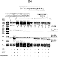
- Enzyme salt tolerance test> A salt tolerance test was performed on the DNA polymerase to verify that the elongation reaction is possible under high salt concentration conditions.
- FIG. 5 is a diagram showing a structural formula of dNTP.
- the partial double-stranded DNA concentration was 500 nM
- the dNTP concentration was 100 ⁇ M
- the Bst 3.0 DNA polymerase concentration was 6000 units / ml.
- a sample was prepared by adding potassium chloride to the buffer solution so that the concentration thereof was 1.0 M, 1.5 M, 2.0 M, 2.5 M or 3.0 M.
- the extension reaction was performed for 1 hour with the reaction temperature set at 37 ° C., which is the nanopore measurement condition.
- the product after the completion of the extension reaction was electrophoresed on Tapestation 4200 manufactured by Agilent Technologies. Results are shown in FIG.
- FIG. 6 is a diagram showing the results of electrophoresis in a salt tolerance test. As is clear from FIG. 6, it was found that Bst 3.0 DNA polymerase exhibits a good elongation reaction even in a salt solution having a high concentration of 3.0 M KCl.
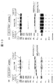
- FIG. 7 is a diagram showing the results of electrophoresis in a salt tolerance test of Csa DNA polymerase. As shown in FIG. 7, it was confirmed that Csa DNA polymerase is capable of elongation reaction under the condition of 1.0 M KCl concentration.
- FIG. 8 is a diagram showing the results of electrophoresis in a salt tolerance test of 96-7 DNA polymerase. As shown in FIG. 8, it was confirmed that 96-7 DNA polymerase is capable of extension reaction under the condition of 3.0 M KCl concentration.
- the phi29 DNA polymerase is known as a conventional DNA polymerase used as a molecular motor. Therefore, it was verified that the conventional phi29 DNA polymerase could not successfully perform the elongation reaction under the high salt concentration condition.
- phi29 DNA polymerase was used instead of Bst 3.0 DNA polymerase, the sample was prepared so that the concentration of phi29 DNA polymerase was 500 units / ml, and the KCl concentration was 30 mM, 100 mM, 200 mM or 300 mM.
- An extension reaction was performed in the same manner as in Example 1, and the product after the reaction was electrophoresed. The results are shown in Fig. 9.
- FIG. 9 is a diagram showing the results of electrophoresis in the salt tolerance test of phi29 DNA polymerase.
- the KCl concentration is as low as 30 mM
- an extension reaction is carried out, and a band appears near the original band with a total length of 80 bp.
- the band near 80 bp became thinner and the band at the unreacted band position became darker.
- the KCl concentration of 300 mM almost no band around 80 bp was confirmed, and it was revealed that the elongation reaction could not be performed under the KCl concentration of 300 mM or more. Therefore, it was revealed that the conventional phi29 DNA polymerase cannot perform the extension reaction well under a high salt concentration.
- FIG. 10 is a diagram showing the results of electrophoresis in a termination test of extension reaction with a spacer. As shown in FIG. 10 (a), it was confirmed that the elongation reaction can be stopped when the number of SpacerC3 is 2 to 4 under the condition that the KCl concentration is 0M. On the other hand, it was revealed that the extension reaction cannot be stopped when the number of SpacerC3 is one, because the extension reaction is carried out.
- dNTP which is an ordinary substrate of DNA polymerase
- an NTP analog can be used as a substrate.
- the NTP analog has a structure in which a part of the structure of dNTP is modified.
- Examples of NTP analogs include those in which oxygen between ⁇ and ⁇ site phosphorus or oxygen between ⁇ and ⁇ site phosphorus is substituted with NH, hydrocarbon, etc., and those in which the five-membered ring sugar structure is ribose. Can be mentioned.
- NTP analogs include NMP-PNP, 5'-bromo-dNTP, 5'-bromo-NTP, 5'-amino-allyl-dNTP, 5'-amino-allyl-NTP, dNMP-NPP, NMP. -PPP and the like can be mentioned. Among them, NMP-PNP is particularly preferable because it can carry and control signals in units of one base.
- FIG. 12 is a diagram showing the structural formula of NMP-PNP.
- NMP-PNP has a structure in which the five-membered ring sugar structure is ribose and the oxygen between the ⁇ and ⁇ site phosphorus is replaced with NH.
- N of NMP means N of nucleoside, and actual reagent names use abbreviations of the respective bases (A, G, T, C, U).
- the official name of NMP-PNP is, for example, adenosine-5 ′-[( ⁇ , ⁇ ) -imido] triphosphate when the nucleoside is adenosine (A), and NMP-PNP, NppNHp, etc. are used as common names. ing.
- NTP analogs when dNMP-NPP or NMP-NPP is used as a substrate, a single base signal may not be clearly separated.
- dNMP-NPP also known as dNpNHpp, formal name: 2'-deoxyadenosine-5 '-[( ⁇ , ⁇ ) -imido] triphosphate (when the nucleoside is adenosine)
- dNpNHpp formal name: 2'-deoxyadenosine-5 '-[( ⁇ , ⁇ ) -imido] triphosphate (when the nucleoside is adenosine)
- NMP-NPP also known as NpNHpp, formal name: adenosine-5 ′-[( ⁇ , ⁇ ) -imido] triphosphate (when the nucleoside is adenosine)
- NpNHpp formal name: adenosine-5 ′-[( ⁇ , ⁇ ) -imido] triphosphate (when the nucleoside is adenosine)
- NpNHpp formal name: adenosine-5 ′-[( ⁇ , ⁇ ) -imido] triphosphate (when the nucleoside is adenosine)
- ⁇ has a structure in which oxygen between ⁇ -site phosphorus is replaced with NH.
- modified bases include 5-methylcytosine, N6-methyladenosine, N3-methyladenosine, N7-methylguanosine, and 5-hydroxymethylcytosine.
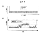
- a partial double-stranded DNA having a short tandem repeat sequence with a total length of 100 bases in which an adenine base (A) and a cytosine base (C) are alternately repeated one by one was used.
- the final volume was 200 ⁇ L, and the partial double-stranded DNA concentration was 10 nM, the dNTP concentration was 100 ⁇ M, the Bst 3.0 DNA polymerase concentration was 600 units / ml, and the potassium chloride concentration was 3.0 M. ⁇ Isothermal Buffer II) was added to prepare a sample.
- the ion current was measured using the analyzer 1 having a Si 3 N 4 film nanopore. As shown in the sequence of Table 5, iSpC3 (SpacerC3) was bound to the position shown by Z as a spacer. The applied voltage was 0.1V. The results are shown in Fig. 11 (b).
- the ideal signal obtained is a pattern signal in which two-level signals are alternately repeated about 50 times.
- FIG. 11 (b) when dNTP was used as a substrate as in Reference Example 1, although a 2-level signal could be barely observed, a pattern in which 2-level signals were alternately repeated about 50 times was obtained. Turned out not.
- the blocking current of the nanopore was measured using Bst 3.0 DNA polymerase as the molecular motor and NMP-PNP as the substrate as follows. From this, it was confirmed that the molecular motor can convey the biopolymer so that the elongation reaction occurs even under a high salt concentration condition and the signal of one base unit becomes clear.
- Example 1 A sample was prepared in the same manner as in Reference Example 7 except that NMP-PNP was used as the substrate, and the ion current was measured using the analyzer 1. The results are shown in Fig. 13.
- FIG. 13A shows a measured signal
- FIG. 13B shows a standardized waveform in which only the level is extracted from the measured signal.
- Example 5 Salt resistance test> [Examples 2 and 3]
- the results in FIG. 13 also indirectly show that the extension reaction of the polymerase is carried out when NMP-PNP is used as a substrate under the conditions of nanopore analysis, but the same test as in Reference Example 1 (FIG. 6) It was directly verified that the extension reaction was carried out even when the salt concentration was high when NMP-PNP was used as a substrate.
- NMP-PNP was used instead of dNTP, and the extension reaction was performed in the same manner as in Reference Example 1 except that the potassium chloride concentration was 0 M (Example 2) or 3.0 M (Example 3), The product after the reaction was electrophoresed. The results are shown in Fig. 14.
- FIG. 14 is a diagram showing the results of electrophoresis in a salt tolerance test when NMP-PNP was used as a substrate for Bst 3.0 DNA polymerase. As is clear from FIG. 14, Bst 3.0 DNA polymerase shows a good elongation reaction even in the case of the NTP analog NMP-PNP in a salt solution having a high concentration of 3.0 M KCl. Was found.
- Example 6 Measurement of ion current> [Reference Examples 8 and 9]
- a signal of one base unit is not clearly generated by any NTP analog. Therefore, the ion current was measured in the same manner as in Reference Example 7 except that dNMP-NPP (Reference Example 8) or NMP-NPP (Reference Example 9) was used as the substrate.
- FIG. 15 (a) shows the waveform of the ionic current when dNMP-NPP was used as the substrate
- FIG. 15 (b) shows the waveform of the ionic current when NMP-NPP was used as the substrate.
- FIG. 17 is a schematic diagram showing the configuration of the analysis device 2 according to the second embodiment.
- the biopolymer analysis device 200 of the analyzer 2 according to the second embodiment is different from that of the first embodiment in that it includes a plurality of nanopores 101 and the liquid tank 104B is divided into a plurality of liquid tanks.
- the biopolymer analysis device 200 includes a plurality of partition bodies 102 each having a nanopore 101 formed therein.
- the partition 102 is composed of a thin film 102A on which the nanopore 101 is formed, and thin film fixing members 102B and 102C that sandwich the thin film 102A.
- the nanopore 101 may be formed at any position on the thin film 102A.
- the interval for disposing the plurality of thin films 102A is preferably 0.1 mm to 10 mm, more preferably 0.5 mm to 4 mm, depending on the capacity of the electrodes used and the electric measurement system.
- the thin film fixing member 102B and the thin film 102A form a part of the structure of the liquid tank 104A. Further, the thin film 102A and the thin film fixing member 102C form a part of the structure of the liquid tank 104B.
- the thin film fixing member 102C has four spaces separated by three partition walls, and these spaces are respectively used as the liquid tank 104B.
- the liquid tank 104A is used as a common liquid tank for the four liquid tanks 104B located on the lower side.
- the number of liquid tanks 104B is not limited to four and can be changed arbitrarily.
- the dimension of the thin film 102A exposed at the through hole provided in the thin film fixing members 102B and 102C is an area where two or more nanopores 101 are difficult to be formed when the nanopores 101 are formed by applying a voltage, and the strength is allowable.
- the area must be The area is, for example, 100 nm to 500 nm.
- a film thickness of 3 nm to 7 nm that can form the nanopore 101 having an effective film thickness equivalent to one base is suitable.
- Each liquid tank 104B is provided with a single nanopore 101 and an electrode 105B, and the liquid tanks 104B are insulated from each other by the partition wall of the thin film fixing member 102C. Therefore, the current flowing through each nanopore 101 can be measured independently.
- the biopolymer analysis device 200 of this embodiment has the plurality of nanopores 101, it is possible to efficiently perform nanopore analysis of the biopolymer.
- the nanopore device for analyzing the biopolymer according to the above embodiment includes the above-mentioned configuration as an element.
- the nanopore device can be provided together with instructions describing use procedures, usage amounts, and the like.
- the control chain, the NTP analog, etc. may be provided in a state in which they can be used immediately, or may be provided in a state in which only the biopolymer to be measured is not bound. Such forms and adjustments can be understood by those skilled in the art.
- the nanopore may be provided in a state in which the nanopore is formed in a ready-to-use state, or may be provided in a state in which the nanopore is formed.
- the present disclosure is not limited to the above-described embodiments and includes various modifications.
- the above-described embodiments have been described in detail in order to explain the present disclosure in an easy-to-understand manner, and it is not necessary to include all the configurations described.
- part of one embodiment can be replaced with the configuration of another embodiment.
- the configuration of another embodiment can be added to the configuration of one embodiment.
- a part of the configuration of each embodiment may be added, deleted, or replaced with a part of the configuration of another embodiment.
- Analytical apparatus 100 200 ... Biopolymer analysis device 101 ... Nanopore 102A ... Thin film 103 ... Electrolyte solution 104A, 104B ... Liquid tank 105A, 105B ... Electrode 106 ... Ammeter 107 ... Power supply 108 ... Computer 109 ... Living body Polymer 110 ... Molecular motor 111 ... Control chain 112 ... Primer 113 ... Spacer 301 ... Force to pull up biopolymer 302 ... Force that biopolymer receives from electric field
Abstract
Dispositif d'analyse de polymère biologique, par lequel le transport est bien maîtrisé par une unité monomère, un analyseur utilisant ledit dispositif et un procédé d'analyse. Le dispositif d'analyse de polymère biologique selon la présente invention comprend : un film mince ayant des nanopores; des premier et second réservoirs de liquide renfermant une solution électrolytique, lesdits réservoirs de liquide étant disposés de façon à prendre en sandwich le film mince entre eux; et une unité d'application de champ externe qui applique un champ externe entre les premier et second réservoirs de liquide. Ce dispositif d'analyse de polymère biologique est caractérisé en ce que : un polymère biologique, une enzyme se liant au polymère biologique et un analogue de NTP servant de substrat de l'enzyme sont introduits dans le premier réservoir de liquide; lorsque le champ externe est appliqué, le polymère biologique est introduit dans les nanopores et ainsi l'enzyme incorpore l'analogue de NTP dans celui-ci; et le polymère biologique est par conséquent transporté à l'intérieur des nanopores.
Priority Applications (1)
| Application Number | Priority Date | Filing Date | Title |
|---|---|---|---|
| PCT/JP2018/039466 WO2020084705A1 (fr) | 2018-10-24 | 2018-10-24 | Dispositif d'analyse de polymère biologique, analyseur l'utilisant et procédé d'analyse |
Applications Claiming Priority (1)
| Application Number | Priority Date | Filing Date | Title |
|---|---|---|---|
| PCT/JP2018/039466 WO2020084705A1 (fr) | 2018-10-24 | 2018-10-24 | Dispositif d'analyse de polymère biologique, analyseur l'utilisant et procédé d'analyse |
Publications (1)
| Publication Number | Publication Date |
|---|---|
| WO2020084705A1 true WO2020084705A1 (fr) | 2020-04-30 |
Family
ID=70330596
Family Applications (1)
| Application Number | Title | Priority Date | Filing Date |
|---|---|---|---|
| PCT/JP2018/039466 WO2020084705A1 (fr) | 2018-10-24 | 2018-10-24 | Dispositif d'analyse de polymère biologique, analyseur l'utilisant et procédé d'analyse |
Country Status (1)
| Country | Link |
|---|---|
| WO (1) | WO2020084705A1 (fr) |
Cited By (3)
| Publication number | Priority date | Publication date | Assignee | Title |
|---|---|---|---|---|
| US9575230B2 (en) | 2010-05-03 | 2017-02-21 | Basf Se | Color filter for low temperature applications |
| CN114705743A (zh) * | 2022-04-01 | 2022-07-05 | 南京师范大学 | 一种基于纳米孔的实验装置及实验方法 |
| WO2022264243A1 (fr) * | 2021-06-15 | 2022-12-22 | 株式会社日立ハイテク | Procédé d'analyse de biomolécules, réactif d'analyse de biomolécules, et dispositif d'analyse de biomolécules |
Citations (7)
| Publication number | Priority date | Publication date | Assignee | Title |
|---|---|---|---|---|
| JP2014534812A (ja) * | 2011-10-21 | 2014-12-25 | オックスフォード ナノポール テクノロジーズ リミテッド | 酵素法 |
| JP2017503473A (ja) * | 2013-11-26 | 2017-02-02 | イルミナ インコーポレイテッド | ポリヌクレオチド配列決定のための組成物及び方法 |
| WO2017075421A1 (fr) * | 2015-10-29 | 2017-05-04 | Temple University-Of The Commonwealth System Of Higher Education | Modification des extrémités 3' d'acides nucléiques par l'adn polymérase thêta |
| WO2017100027A1 (fr) * | 2015-12-08 | 2017-06-15 | Quantapore, Inc. | Procédé de translocation d'acides nucléiques via des nanopores |
| WO2017110226A1 (fr) * | 2015-12-24 | 2017-06-29 | 株式会社日立ハイテクノロジーズ | Réactif de mesure et dispositif d'analyse permettant d'analyser un biopolymère |
| JP2017163920A (ja) * | 2016-03-17 | 2017-09-21 | 国立研究開発法人産業技術総合研究所 | 核酸増幅法 |
| JP2017536103A (ja) * | 2014-10-17 | 2017-12-07 | オックスフォード ナノポール テクノロジーズ リミテッド | 分析物を膜貫通ポアに送達する方法 |
-
2018
- 2018-10-24 WO PCT/JP2018/039466 patent/WO2020084705A1/fr active Application Filing
Patent Citations (7)
| Publication number | Priority date | Publication date | Assignee | Title |
|---|---|---|---|---|
| JP2014534812A (ja) * | 2011-10-21 | 2014-12-25 | オックスフォード ナノポール テクノロジーズ リミテッド | 酵素法 |
| JP2017503473A (ja) * | 2013-11-26 | 2017-02-02 | イルミナ インコーポレイテッド | ポリヌクレオチド配列決定のための組成物及び方法 |
| JP2017536103A (ja) * | 2014-10-17 | 2017-12-07 | オックスフォード ナノポール テクノロジーズ リミテッド | 分析物を膜貫通ポアに送達する方法 |
| WO2017075421A1 (fr) * | 2015-10-29 | 2017-05-04 | Temple University-Of The Commonwealth System Of Higher Education | Modification des extrémités 3' d'acides nucléiques par l'adn polymérase thêta |
| WO2017100027A1 (fr) * | 2015-12-08 | 2017-06-15 | Quantapore, Inc. | Procédé de translocation d'acides nucléiques via des nanopores |
| WO2017110226A1 (fr) * | 2015-12-24 | 2017-06-29 | 株式会社日立ハイテクノロジーズ | Réactif de mesure et dispositif d'analyse permettant d'analyser un biopolymère |
| JP2017163920A (ja) * | 2016-03-17 | 2017-09-21 | 国立研究開発法人産業技術総合研究所 | 核酸増幅法 |
Cited By (4)
| Publication number | Priority date | Publication date | Assignee | Title |
|---|---|---|---|---|
| US9575230B2 (en) | 2010-05-03 | 2017-02-21 | Basf Se | Color filter for low temperature applications |
| US10690825B2 (en) | 2010-05-03 | 2020-06-23 | Basf Se | Color filter for low temperature applications |
| WO2022264243A1 (fr) * | 2021-06-15 | 2022-12-22 | 株式会社日立ハイテク | Procédé d'analyse de biomolécules, réactif d'analyse de biomolécules, et dispositif d'analyse de biomolécules |
| CN114705743A (zh) * | 2022-04-01 | 2022-07-05 | 南京师范大学 | 一种基于纳米孔的实验装置及实验方法 |
Similar Documents
| Publication | Publication Date | Title |
|---|---|---|
| RU2765308C2 (ru) | Способы, композиции и устройства для хранения информации | |
| US11054390B2 (en) | Two-chamber dual-pore device | |
| EP3387432B1 (fr) | Nanopores modifiés, compositions les comprenant et leurs utilisations | |
| US9863912B2 (en) | Dual-pore device | |
| EP2815235B1 (fr) | Methode aptamere | |
| WO2020084705A1 (fr) | Dispositif d'analyse de polymère biologique, analyseur l'utilisant et procédé d'analyse | |
| EP2994751B1 (fr) | Methode d'analyse pour des complexes de cibles biologiques avec un nanopore et protéine de fusion agent de liaison | |
| JP2017221203A (ja) | 結合方法 | |
| CN116334198A (zh) | 分析物的测定和表征方法及试剂盒 | |
| KR20170106487A (ko) | 시료 배경으로부터의 표적 폴리뉴클레오티드의 나노포어 검출 | |
| JP2017530714A (ja) | 方法 | |
| US20160187282A1 (en) | Device for single molecule detection and fabrication methods thereof | |
| WO2020044780A1 (fr) | Dispositif d'analyse de biomolécule | |
| TW201502276A (zh) | 單分子無標定核酸定序方法 | |
| JP7132100B2 (ja) | 生体分子分析装置及び生体分子分析方法 | |
| WO2021124468A1 (fr) | Complexe moléculaire et procédé d'analyse de biopolymère | |
| WO2022024335A1 (fr) | Méthode d'analyse de biomolécule et dispositif d'analyse de biomolécule | |
| US20200024650A1 (en) | Target Polynucleotide Detection and Sequencing by Incorporation of Modified Nucleotides for Nanaopore Analysis | |
| WO2022264243A1 (fr) | Procédé d'analyse de biomolécules, réactif d'analyse de biomolécules, et dispositif d'analyse de biomolécules | |
| WO2023038830A1 (fr) | Conception de circuit pour appliquer différentes tensions dans un réseau de nanopores | |
| JP6513705B2 (ja) | 固体状態ナノ細孔を用いた修飾生物学的分子の選択的分析 | |
| CN116200477A (zh) | 包含联合阻滞元件的衔接体、构建体、方法和应用 |
Legal Events
| Date | Code | Title | Description |
|---|---|---|---|
| 121 | Ep: the epo has been informed by wipo that ep was designated in this application |
Ref document number: 18937747 Country of ref document: EP Kind code of ref document: A1 |
|
| NENP | Non-entry into the national phase |
Ref country code: DE |
|
| 122 | Ep: pct application non-entry in european phase |
Ref document number: 18937747 Country of ref document: EP Kind code of ref document: A1 |
|
| NENP | Non-entry into the national phase |
Ref country code: JP |