WO2020084705A1 - Biological polymer analysis device, analyzer using same, and analysis method - Google Patents
Biological polymer analysis device, analyzer using same, and analysis method Download PDFInfo
- Publication number
- WO2020084705A1 WO2020084705A1 PCT/JP2018/039466 JP2018039466W WO2020084705A1 WO 2020084705 A1 WO2020084705 A1 WO 2020084705A1 JP 2018039466 W JP2018039466 W JP 2018039466W WO 2020084705 A1 WO2020084705 A1 WO 2020084705A1
- Authority
- WO
- WIPO (PCT)
- Prior art keywords
- biopolymer
- nanopore
- dna
- enzyme
- dna polymerase
- Prior art date
Links
Images


Classifications
-
- C—CHEMISTRY; METALLURGY
- C12—BIOCHEMISTRY; BEER; SPIRITS; WINE; VINEGAR; MICROBIOLOGY; ENZYMOLOGY; MUTATION OR GENETIC ENGINEERING
- C12M—APPARATUS FOR ENZYMOLOGY OR MICROBIOLOGY; APPARATUS FOR CULTURING MICROORGANISMS FOR PRODUCING BIOMASS, FOR GROWING CELLS OR FOR OBTAINING FERMENTATION OR METABOLIC PRODUCTS, i.e. BIOREACTORS OR FERMENTERS
- C12M1/00—Apparatus for enzymology or microbiology
Definitions
- the present disclosure relates to a biopolymer analysis device, an analysis device using the same, and an analysis method.
- An analyzer using a nanopore device has been developed as an analyzer for analyzing the monomer sequence of a biopolymer.
- Such an analyzer is used as a DNA base sequence analysis system (DNA sequencer) when the biopolymer is DNA, and as an amino acid sequence analysis system (amino acid sequencer) when the biopolymer is protein. It is expected as a system capable of decoding long sequence lengths.
- a nanopore device is a thin film with pores (nanopores) with a diameter of several ⁇ to several nanometers and a liquid tank on each side of a thin film with a thickness of several ⁇ to several tens of nanometers.
- An electrolyte solution is passed through the nanopores by creating a potential difference across both ends of the nanopore.
- a pH neutral aqueous potassium chloride solution is typically used as the electrolyte solution.
- the ionic current around the nanopore changes in a pattern according to the monomer arrangement pattern.
- the ionic current is proportional to the cross-sectional area of the nanopore as a first approximation.
- the biopolymer blocks the nanopore and reduces the effective cross-sectional area through which the ions can pass, thus reducing the ionic current. This reduction amount is called a blocking current.
- Such a blocking current type nanopore device can analyze a monomer arrangement of a biopolymer by detecting a change in ionic current. Since the analysis accuracy of the monomer array is determined by the amount of change in ion current, the larger the difference in ion current amount between monomers, the better.
- nanopore devices There are two types of nanopore devices: a bio-nanopore type that uses a protein with a central pore that is embedded in a lipid bilayer, and a solid nanopore type that uses an insulating thin film formed by a semiconductor processing process.
- a bio-nanopore type that uses a protein with a central pore that is embedded in a lipid bilayer
- a solid nanopore type that uses an insulating thin film formed by a semiconductor processing process.
- the pores (diameter 1.2 nm, thickness 0.6 nm) of the modified protein (Mycobacterium smegmatisporinA (MspA) etc.) embedded in the lipid bilayer membrane are used as the biopolymer detector to detect ionic current. Measure the amount of change.
- MspA Mycobacterium smegmatisporinA
- the solid nanopore type a structure in which nanopores are formed in a thin film of silicon nitride (SiN) which is a semiconductor material or a thin film composed of a monomolecular layer such as graphene or molybdenum disulfide is used.
- SiN silicon nitride
- a monomolecular layer such as graphene or molybdenum disulfide
- Patent Document 1 As a solid nanopore type nanopore DNA sequencer, it has been reported that the blocking current amount of homopolymer adenine base, cytosine base, thymine base, and guanine base was measured using an aqueous potassium chloride solution under neutral pH (Patent Document 1).
- a DNA polymerase binds a primer to DNA serving as a template, passes a single-stranded portion through a nanopore, and an elongation reaction occurs when the DNA polymerase binds to a primer end, so that the DNA is pulled by an electric field.
- the delivery of DNA is realized against the force.
- an ion current signal corresponding to the base species can be obtained (Patent Documents 2 to 5).
- the problem with the above transport control method is that it is difficult to control the enzyme under high salt concentration.
- the electrical conductivity of the nanopores is higher under a high salt concentration, so that the fluctuation amount of the blockade current signal corresponding to the base sequence at the time of passing through the DNA is increased, while the noise signal is increased. Since it is almost constant, measurement can be realized with a high SN ratio (Signal / Noise ratio).
- the enzyme is inactivated and cannot function as a molecular motor, so that there is a trade-off problem that DNA transport cannot be controlled.
- a biopolymer analysis device that satisfactorily controls the transport of each monomer, an analysis apparatus using the same, and an analysis method are provided.
- a biopolymer analysis device includes a thin film having nanopores, a first liquid tank and a second liquid tank that are arranged so as to sandwich the thin film, and store an electrolyte solution, An external field applying unit for applying an external field between the first liquid tank and the second liquid tank, wherein the first liquid tank has a biological polymer, an enzyme that binds to the biological polymer, and the enzyme. Is introduced into the nanopore by the application of the external field, the enzyme takes up the NTP analog, and the biopolymer is transported in the nanopore. It is characterized by
- the schematic diagram which shows the conveyance control process of the biopolymer in the nanopore vicinity. The figure explaining the state of a living body polymer in the case where an extension reaction is started before introducing a nanopore of a living body polymer (a), and when an extension reaction is started after introducing a living body's nanopore (b).
- the figure which shows the structural formula of dNTP The figure which shows the result of the electrophoresis in the salt tolerance test of Bst 3.0 DNA polymerase. The figure which shows the result of the electrophoresis in the salt tolerance test of Csa DNA polymerase.
- 96-7 is a view showing a result of electrophoresis in a salt tolerance test of 96-7 DNA polymerase.
- phi29 is a diagram showing the results of electrophoresis in a salt tolerance test of DNA polymerase.
- the figure which shows the structural formula of NMP-PNP The figure which shows the result of the nanopore analysis when NMP-PNP is used as a substrate for Bst 3.0 DNA polymerase.
- FIG. 1 is a schematic diagram showing the configuration of an analyzer 1 according to the first embodiment.
- the analysis apparatus 1 includes a biopolymer analysis device 100, an ammeter 106, a power supply 107, and a computer 108 (analysis unit).
- the biological polymer to be analyzed is, for example, DNA or RNA whose nucleic acid is a monomer, or a polypeptide or protein whose amino acid is a monomer.
- the analyzer 1 is a DNA sequencer that analyzes DNA will be described as an example.
- the biopolymer analysis device 100 includes a thin film 102A having nanopores 101, liquid tanks 104A and 104B (first liquid tank and second liquid tank) containing an electrolyte solution 103, and electrodes 105A and 105B (external field application unit). Equipped with.
- the biopolymer analysis device 100 adopts a method of introducing the biopolymer 109 into the nanopore 101 by electrophoresis.
- the method of introducing the biopolymer 109 into the nanopore 101 is not limited to this, and other methods may be adopted.
- the thin film 102A may be a lipid bilayer (bio-type nanopore) composed of an amphipathic molecule layer in which a protein having a pore in the center is embedded, or a thin film (Material formed by semiconductor microfabrication technology ( It may be a solid type nanopore).
- Materials that can be formed by the semiconductor fine processing technology include, for example, silicon nitride (SiN), silicon oxide (SiO 2 ), silicon oxynitride (SiON), hafnium oxide (HfO 2 ), molybdenum disulfide (MoS 2 ), graphene, and the like. Is mentioned.
- the thickness of the thin film 102A is preferably 1 ⁇ to 200 nm, more preferably 1 ⁇ to 100 nm, still more preferably 1 ⁇ to 50 nm, and for example, about 5 nm.
- the depth of the nanopore 101 can be adjusted by adjusting the thickness of the thin film 102A.
- the depth of the nanopore 101 is preferably 2 times or more, more preferably 3 times or more, further preferably 5 times or more as large as the monomer unit constituting the biopolymer 109.
- the depth of the nanopore 101 is preferably, for example, 3 bases or more, that is, about 1 nm or more. This allows the biopolymer 109 to enter the nanopore 101 while controlling its shape and moving speed, and enables highly sensitive and highly accurate analysis.
- the shape of the cross section of the nanopore 101 in the horizontal plane is basically circular, but it may be elliptical or polygonal.
- the liquid tanks 104A and 104B are arranged on both sides of the thin film 102A and filled with the electrolyte solution 103. Electrode 105A is arranged in liquid tank 104A, and electrode 105B is arranged in liquid tank 104B.
- the liquid tanks 104A and 104B are formed of a material, shape and size that do not affect the measurement of the blocking current.
- the capacity of the electrolyte solution 103 is, for example, on the order of microliters or milliliters. Details of the electrolyte solution 103 will be described later.
- the biopolymer 109 is introduced into the liquid tank 104A during the nanopore analysis in a state of being bound to the control chain 111 by the pretreatment.
- the electrodes 105A and 105B are preferably made of a material capable of performing an electron transfer reaction (Faraday reaction) with the electrolyte in the electrolyte solution 103, and typically made of silver halide or alkali silver halide. To be done. From the viewpoint of potential stability and reliability, it is preferable to use silver or silver chloride.
- Faraday reaction electron transfer reaction
- the electrodes 105A and 105B may be made of a material that becomes a polarized electrode, for example, gold or platinum. In that case, in order to secure a stable ionic current, it is preferable to add a substance capable of assisting the electron transfer reaction to the electrolyte solution 103, such as potassium ferricyanide or potassium ferrocyanide. Alternatively, it is preferable to immobilize a substance capable of performing an electron transfer reaction, such as ferrocene, on the surface of the polarized electrode.
- the electrodes 105A and 105B may be entirely made of the above material, or the surface of a base material (copper, aluminum, etc.) may be coated with the above material.
- the shapes of the electrodes 105A and 105B are not particularly limited, but a shape that increases the surface area in contact with the electrolyte solution 103 is preferable.
- connection terminals electrically connected to the electrodes 105A and 105B are provided on the outer peripheral surface of the biopolymer analysis device 100, whereby the electrodes 105A and 105B are connected to the power source 107 and It is connected to the ammeter 106.
- the biopolymer 109 passes through the nanopore 101 while being coupled to the molecular motor 110. Since the molecular motor 110 is generally larger than the diameter of the nanopore 101, it cannot pass through the nanopore 101. In order to realize this limitation, the diameter of the nanopore 101 is in the range of 0.8 nm, which is the lower limit that allows single-stranded DNA to pass, and 3 nm, which is the upper limit that the enzyme that is the molecular motor 110 does not pass. Is preferred.
- the ammeter 106 measures an ionic current (blocking current) flowing between the electrodes 105A and 105B. Although not shown, it has an amplifier for amplifying a current flowing between the electrodes 105A and 105B, and an analog / digital converter. The ammeter 106 is connected to the computer 108, and the analog / digital converter outputs the current value of the detected ion current to the computer 108 as a digital signal.
- the computer 108 acquires the monomer arrangement information of the biopolymer based on the detected ionic current value. Further, the computer 108 records the current value and the acquired monomer arrangement information.
- the current value measured in the absence of the biopolymer 109 is used as a reference (pore current), and the current observed when the biopolymer 109 is sealed (nanopore).
- the blockage by the biopolymer 109 of 101) is measured, and the passage speed and state of the molecule are observed.
- the acquired current value returns to the pore current. It is possible to analyze the nanopore passage speed of the biopolymer 109 from this blocking time, and to analyze the characteristics of the biopolymer 109 from the blocking amount.
- the configuration may be such that the monomer arrangement information of the biopolymer 109 is acquired based on the optical signal. That is, a method may be used in which each monomer is labeled with a characteristic fluorescence wavelength, and the fluorescence signal is measured to determine each monomer sequence.
- the power supply 107, the ammeter 106, and the computer 108 are not separate members from the biological polymer analysis device 100, but the power supply 107, the ammeter 106, and the computer 108 are used as the biological polymer analysis device 100. It may be integrated with.
- the nanopore 101 is formed on the thin film 102A by, for example, electron beam irradiation by a transmission electron microscope or the like, or dielectric breakdown by voltage application.
- the nanopore 101 can be formed by applying a voltage, for example, by the following procedure.
- the Si 3 N 4 thin film is made hydrophilic by Ar / O 2 plasma (manufactured by Samco Co., Ltd.) under the conditions of 10 WW, 20 sccm, 20 Pa, and 45 sec.
- the thin film 102A is set on the biopolymer analysis device 100.
- the liquid tanks 104A and 104B are filled with the electrolyte solution 103, the electrodes 105A and 105B are introduced into the liquid tanks 104A and 104B, and a voltage is applied.
- the liquid tank 104B located on the lower side is called a cis tank
- the liquid tank 104A located on the upper side is called a trans tank.
- the voltage Vcis applied to the electrode on the cis tank side is set to 0 V
- the voltage Vtrans is applied to the electrode on the trans tank side.
- the voltage Vtrans is applied as a pulse voltage by, for example, a pulse generator (41501B SMU AND Pulse Generator Expander, manufactured by Agilent Technologies).
- the process of applying a voltage to form the nanopore 101 is controlled by, for example, a self-made program (Excel VBA, Visual Basic for Applications).
- the current value after applying the pulse voltage can be read by an ammeter 106 (4156B PRECISION SEMICONDUCTOR ANALYZER, manufactured by Agilent Technologies).
- the diameter of the nanopore 101 can be estimated from the ion current value.
- a current value condition (threshold current) is selected in accordance with the diameter of the nanopore 101 formed before the application of the pulse voltage, and the diameter of the nanopore 101 is successively increased to obtain the target diameter.
- the criteria for selecting the conditions are shown in Table 1.
- the n-th pulse voltage application time t n (where n> 2 is an integer) is determined by the following equation.
- the transport control of the biopolymer 109 in this embodiment will be described.
- the transport control of the biopolymer 109 is mainly performed by the molecular motor 110 using an enzyme.
- an enzyme capable of binding to the biopolymer 109 can be used without particular limitation.
- the biopolymer 109 is DNA
- DNA polymerase, DNA helicase, DNA exonuclease, DNA transposase and the like can be mentioned.
- the biological polymer 109 is RNA, RNA polymerase, RNA helicase, RNA exonuclease, RNA transposase and the like can be mentioned.
- the molecular motor 110 and the substrate are introduced into the liquid tank 104A during nanopore analysis by the analyzer 1.
- control chain 111 is bonded to the biopolymer 109 that is the reading target.
- the target of the reading of the monomer sequence is a DNA chain which is a main chain of single-stranded or partially single-stranded DNA, and a control chain 111 in the main chain. It is included.
- the biopolymer 109 more preferably satisfies the following (a) to (c).
- the control chain 111 exists in the biopolymer 109 to be read.
- the primer 112 is bound to the control chain 111.
- the spacer 113 is present in the control chain 111.
- the primer 112 is a DNA sequence that is a complementary strand of the control strand 111.
- the spacer 113 has a role as a switch that controls the reaction of the molecular motor 110, and normally stops the reaction of the molecular motor 110. However, when the measurement is performed by the nanopore 101, that is, a force is applied to the molecule, It has a function of starting the reaction of the motor 110.
- the spacer 113 is preferably abasic, and is also preferably a linear linking body.
- the spacer arrangement length may be 1 base or more from the primer connecting portion, but it is preferably 2 bases or more, that is, about 0.6 ⁇ 2 nm or more.
- linkers examples include, but are not limited to, SpacerC3 (iSpC3), PC Spacer, Spacer9, Spacer18, dSpacer, hexanediol, linear carbon chain, linear chain.
- suitable linkers include, but are not limited to, SpacerC3 (iSpC3), PC Spacer, Spacer9, Spacer18, dSpacer, hexanediol, linear carbon chain, linear chain.
- suitable linkers include amino acids, straight chain fatty acids, straight chain sugar chains and the like. It is particularly preferable to introduce Spacer C3 continuously for 4 mer or more.
- the biopolymer 109 has a structure of a single-stranded protruding double-stranded DNA (ssDNA-overhang dsDNA) composed of a main-stranded DNA (template) to be read and a complementary-stranded DNA (primer) shorter than the main-stranded DNA. It is preferable to have
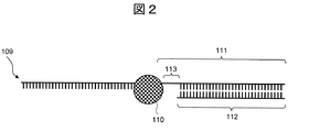
- FIG. 2 is a schematic diagram showing the configuration of the molecular complex according to the present embodiment.
- the molecular motor 110 binds to the single-stranded protruding double-stranded DNA in the vicinity of the boundary between the single-stranded portion and the double-stranded portion to form a molecular complex.
- the molecular motor 110 reacts with the primer 112 to move the relative positions of the main chain DNA and the nanopore 101 in the molecular complex described above by one base, thereby achieving good transport control. Done. This makes it possible to obtain the base sequence information in the main chain DNA.
- the biopolymer 109 is pulled up from the nanopore 101.
- the molecular motor 110 is a DNA helicase or a DNA exonuclease
- the biopolymer 109 is pulled down to the nanopore 101.
- FIG. 3 is a schematic diagram showing the transport control process of the biopolymer 109 in the vicinity of the nanopore 101.
- the biopolymer 109 is introduced into the electrolyte solution 103 in a state where the control chain 111 is bound.
- the molecular motor 110 and the substrate are dissolved in the electrolyte solution 103, and the biopolymer 109 and the molecular motor 110 are bound in the electrolyte solution 103.
- the biopolymer 109 bound to the molecular motor 110 is introduced into the nanopore 101 by the force 302 received from the electric field generated in the vicinity of the nanopore 101.
- the molecular motor 110 since the diameter of the molecular motor 110 is larger than the diameter of the nanopore 101, it cannot proceed toward the exit of the nanopore 101 and stays at the entrance of the nanopore 101.
- the biopolymer 109 having a negative charge further advances toward the exit of the nanopore 101 and undergoes a shape change around the spacer 113.
- the molecular motor 110 binds to the end of the primer 112 in the control chain 111 and starts an extension reaction.
- the biopolymer 109 has an electric field. It is conveyed in the opposite direction. At this time, it is possible to detect a signal change according to the characteristics of the biopolymer 109.
- the voltage V1 used at the time of introduction, the voltage V2 applied at the time of coupling the molecular motor 110, and the voltage V3 at the time of measurement may all be the same.
- the binding force and the pulling force differ depending on the type of the molecular motor 110, there are cases where a desired signal can be detected by using different voltages.
- the force that contributes to the passing speed of the biological polymer 109 also contributes to the friction on the inner wall of the nanopore 101, in addition to the pulling force 301 and the force 302 that is received from the electric field. Therefore, it is necessary to adjust the applied voltage according to the size of the nanopore 101.
- the molecular motor 110 starts the extension reaction from the primer 112 before the biopolymer 109 is introduced into the nanopore 101. This problem will be described with reference to FIG.
- FIG. 4 shows a case where the extension reaction is started before the introduction of the biopolymer 109 into the nanopore 101 (a) and a case where the extension reaction is started after the introduction of the biopolymer 109 into the nanopore 101 (b). It is a figure explaining the mode of 109.
- the extension reaction if the extension reaction is completed before the biopolymer 109 is introduced into the nanopore 101, the biopolymer 109 cannot pass through the nanopore 101. Alternatively, if the extension reaction has proceeded halfway, the analysis length will be shorter than expected.
- the analysis of biopolymers using the nanopore 101 has the advantage of long-chain readability. However, if the extension reaction starts before introduction into the nanopore 101 as described above, the long-chain readability is reduced and throughput is reduced. Bring about a decline.
- the molecular structure having the spacer 113 in the control chain 111 prevents the molecular motor 110 from causing extension reaction in the reaction solution as shown in FIG. 4B.
- the extension reaction that is, the transport control can be started.
- the electrolyte solution 103 includes a buffer suitable for the molecular motor 110.
- Buffers can include, for example, Tris, EDTA, phosphate buffered saline (PBS), nonionic detergents, Tris-HCl, and the like.
- potassium salt such as potassium chloride (KCl)
- ammonium salt such as ammonium chloride (NH 4 Cl) or ammonium sulfate ((NH 4 ) 2 SO 4 )
- magnesium chloride MgCl 2
- commonly used electrolytes such as magnesium salts such as magnesium sulfate (MgSO 4 ) and magnesium sulfate can be used.
- lithium salt, sodium salt, rubidium salt, cesium salt or the like may be used. Of these electrolytes, one kind may be used alone, or two or more kinds may be used in combination.
- a solution containing (NH 4 ) 2 SO 4 , KCl, MgSO 4 , a nonionic surfactant, Tris-HCl, or the like is generally used.
- Urea of 4 M or more, DMSO, DMF, and NaOH in the liquid tank 104B on the side where the molecular motor 110 is not introduced.
- the electric conductivity of the electrolyte solution 103 by increasing the ionic strength, that is, the salt concentration, although it depends on the transport number of the ionic species. Therefore, in the nanopore analysis, from the viewpoint of the SN ratio, it is preferable to perform the measurement under the highest salt concentration possible.
- the concentration of the electrolyte in the electrolyte solution 103 is preferably 1 M or more, and more preferably 3 M or more.
- the upper limit of the concentration of the electrolyte is preferably a saturated concentration at which the electrolyte can be dissolved.
- the electrolyte solution 103 is particularly preferably, for example, typically a 3M potassium chloride aqueous solution.
- a suitable salt concentration is in the range of 50 mM to 300 mM, and therefore the activity may be lost under a salt concentration condition having an ionic strength of 1 M or more, and the extension reaction may not proceed. is there.
- a typical example thereof is A-Family DNA polymerase.
- Bst (Bacillus stearothermophilus) DNA polymerase is particularly preferable because it allows an elongation reaction even under a high salt concentration condition.
- Bst DNA polymerases Bst 3.0 DNA polymerase manufactured by New England Biolabs is particularly preferable for nanopore analysis because it can undergo an elongation reaction even under an extremely high salt concentration condition of 3M or higher.
- Csa DNA polymerase manufactured by Nippon Gene Co., Ltd. or 96-7 DNA polymerase can be used as an enzyme that can function well as molecular motor 110 under high salt concentration conditions. .
- Enzyme salt tolerance test> A salt tolerance test was performed on the DNA polymerase to verify that the elongation reaction is possible under high salt concentration conditions.
- FIG. 5 is a diagram showing a structural formula of dNTP.
- the partial double-stranded DNA concentration was 500 nM
- the dNTP concentration was 100 ⁇ M
- the Bst 3.0 DNA polymerase concentration was 6000 units / ml.
- a sample was prepared by adding potassium chloride to the buffer solution so that the concentration thereof was 1.0 M, 1.5 M, 2.0 M, 2.5 M or 3.0 M.
- the extension reaction was performed for 1 hour with the reaction temperature set at 37 ° C., which is the nanopore measurement condition.
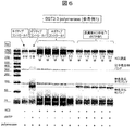
- the product after the completion of the extension reaction was electrophoresed on Tapestation 4200 manufactured by Agilent Technologies. Results are shown in FIG.
- FIG. 6 is a diagram showing the results of electrophoresis in a salt tolerance test. As is clear from FIG. 6, it was found that Bst 3.0 DNA polymerase exhibits a good elongation reaction even in a salt solution having a high concentration of 3.0 M KCl.
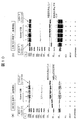
- FIG. 7 is a diagram showing the results of electrophoresis in a salt tolerance test of Csa DNA polymerase. As shown in FIG. 7, it was confirmed that Csa DNA polymerase is capable of elongation reaction under the condition of 1.0 M KCl concentration.
- FIG. 8 is a diagram showing the results of electrophoresis in a salt tolerance test of 96-7 DNA polymerase. As shown in FIG. 8, it was confirmed that 96-7 DNA polymerase is capable of extension reaction under the condition of 3.0 M KCl concentration.
- the phi29 DNA polymerase is known as a conventional DNA polymerase used as a molecular motor. Therefore, it was verified that the conventional phi29 DNA polymerase could not successfully perform the elongation reaction under the high salt concentration condition.
- phi29 DNA polymerase was used instead of Bst 3.0 DNA polymerase, the sample was prepared so that the concentration of phi29 DNA polymerase was 500 units / ml, and the KCl concentration was 30 mM, 100 mM, 200 mM or 300 mM.
- An extension reaction was performed in the same manner as in Example 1, and the product after the reaction was electrophoresed. The results are shown in Fig. 9.
- FIG. 9 is a diagram showing the results of electrophoresis in the salt tolerance test of phi29 DNA polymerase.
- the KCl concentration is as low as 30 mM
- an extension reaction is carried out, and a band appears near the original band with a total length of 80 bp.
- the band near 80 bp became thinner and the band at the unreacted band position became darker.
- the KCl concentration of 300 mM almost no band around 80 bp was confirmed, and it was revealed that the elongation reaction could not be performed under the KCl concentration of 300 mM or more. Therefore, it was revealed that the conventional phi29 DNA polymerase cannot perform the extension reaction well under a high salt concentration.
- FIG. 10 is a diagram showing the results of electrophoresis in a termination test of extension reaction with a spacer. As shown in FIG. 10 (a), it was confirmed that the elongation reaction can be stopped when the number of SpacerC3 is 2 to 4 under the condition that the KCl concentration is 0M. On the other hand, it was revealed that the extension reaction cannot be stopped when the number of SpacerC3 is one, because the extension reaction is carried out.
- dNTP which is an ordinary substrate of DNA polymerase
- an NTP analog can be used as a substrate.
- the NTP analog has a structure in which a part of the structure of dNTP is modified.
- Examples of NTP analogs include those in which oxygen between ⁇ and ⁇ site phosphorus or oxygen between ⁇ and ⁇ site phosphorus is substituted with NH, hydrocarbon, etc., and those in which the five-membered ring sugar structure is ribose. Can be mentioned.
- NTP analogs include NMP-PNP, 5'-bromo-dNTP, 5'-bromo-NTP, 5'-amino-allyl-dNTP, 5'-amino-allyl-NTP, dNMP-NPP, NMP. -PPP and the like can be mentioned. Among them, NMP-PNP is particularly preferable because it can carry and control signals in units of one base.
- FIG. 12 is a diagram showing the structural formula of NMP-PNP.
- NMP-PNP has a structure in which the five-membered ring sugar structure is ribose and the oxygen between the ⁇ and ⁇ site phosphorus is replaced with NH.
- N of NMP means N of nucleoside, and actual reagent names use abbreviations of the respective bases (A, G, T, C, U).
- the official name of NMP-PNP is, for example, adenosine-5 ′-[( ⁇ , ⁇ ) -imido] triphosphate when the nucleoside is adenosine (A), and NMP-PNP, NppNHp, etc. are used as common names. ing.
- NTP analogs when dNMP-NPP or NMP-NPP is used as a substrate, a single base signal may not be clearly separated.
- dNMP-NPP also known as dNpNHpp, formal name: 2'-deoxyadenosine-5 '-[( ⁇ , ⁇ ) -imido] triphosphate (when the nucleoside is adenosine)
- dNpNHpp formal name: 2'-deoxyadenosine-5 '-[( ⁇ , ⁇ ) -imido] triphosphate (when the nucleoside is adenosine)
- NMP-NPP also known as NpNHpp, formal name: adenosine-5 ′-[( ⁇ , ⁇ ) -imido] triphosphate (when the nucleoside is adenosine)
- NpNHpp formal name: adenosine-5 ′-[( ⁇ , ⁇ ) -imido] triphosphate (when the nucleoside is adenosine)
- NpNHpp formal name: adenosine-5 ′-[( ⁇ , ⁇ ) -imido] triphosphate (when the nucleoside is adenosine)
- ⁇ has a structure in which oxygen between ⁇ -site phosphorus is replaced with NH.
- modified bases include 5-methylcytosine, N6-methyladenosine, N3-methyladenosine, N7-methylguanosine, and 5-hydroxymethylcytosine.
- a partial double-stranded DNA having a short tandem repeat sequence with a total length of 100 bases in which an adenine base (A) and a cytosine base (C) are alternately repeated one by one was used.
- the final volume was 200 ⁇ L, and the partial double-stranded DNA concentration was 10 nM, the dNTP concentration was 100 ⁇ M, the Bst 3.0 DNA polymerase concentration was 600 units / ml, and the potassium chloride concentration was 3.0 M. ⁇ Isothermal Buffer II) was added to prepare a sample.
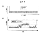
- the ion current was measured using the analyzer 1 having a Si 3 N 4 film nanopore. As shown in the sequence of Table 5, iSpC3 (SpacerC3) was bound to the position shown by Z as a spacer. The applied voltage was 0.1V. The results are shown in Fig. 11 (b).
- the ideal signal obtained is a pattern signal in which two-level signals are alternately repeated about 50 times.
- FIG. 11 (b) when dNTP was used as a substrate as in Reference Example 1, although a 2-level signal could be barely observed, a pattern in which 2-level signals were alternately repeated about 50 times was obtained. Turned out not.
- the blocking current of the nanopore was measured using Bst 3.0 DNA polymerase as the molecular motor and NMP-PNP as the substrate as follows. From this, it was confirmed that the molecular motor can convey the biopolymer so that the elongation reaction occurs even under a high salt concentration condition and the signal of one base unit becomes clear.
- Example 1 A sample was prepared in the same manner as in Reference Example 7 except that NMP-PNP was used as the substrate, and the ion current was measured using the analyzer 1. The results are shown in Fig. 13.
- FIG. 13A shows a measured signal
- FIG. 13B shows a standardized waveform in which only the level is extracted from the measured signal.
- Example 5 Salt resistance test> [Examples 2 and 3]
- the results in FIG. 13 also indirectly show that the extension reaction of the polymerase is carried out when NMP-PNP is used as a substrate under the conditions of nanopore analysis, but the same test as in Reference Example 1 (FIG. 6) It was directly verified that the extension reaction was carried out even when the salt concentration was high when NMP-PNP was used as a substrate.
- NMP-PNP was used instead of dNTP, and the extension reaction was performed in the same manner as in Reference Example 1 except that the potassium chloride concentration was 0 M (Example 2) or 3.0 M (Example 3), The product after the reaction was electrophoresed. The results are shown in Fig. 14.
- FIG. 14 is a diagram showing the results of electrophoresis in a salt tolerance test when NMP-PNP was used as a substrate for Bst 3.0 DNA polymerase. As is clear from FIG. 14, Bst 3.0 DNA polymerase shows a good elongation reaction even in the case of the NTP analog NMP-PNP in a salt solution having a high concentration of 3.0 M KCl. Was found.
- Example 6 Measurement of ion current> [Reference Examples 8 and 9]
- a signal of one base unit is not clearly generated by any NTP analog. Therefore, the ion current was measured in the same manner as in Reference Example 7 except that dNMP-NPP (Reference Example 8) or NMP-NPP (Reference Example 9) was used as the substrate.
- FIG. 15 (a) shows the waveform of the ionic current when dNMP-NPP was used as the substrate
- FIG. 15 (b) shows the waveform of the ionic current when NMP-NPP was used as the substrate.
- FIG. 17 is a schematic diagram showing the configuration of the analysis device 2 according to the second embodiment.
- the biopolymer analysis device 200 of the analyzer 2 according to the second embodiment is different from that of the first embodiment in that it includes a plurality of nanopores 101 and the liquid tank 104B is divided into a plurality of liquid tanks.
- the biopolymer analysis device 200 includes a plurality of partition bodies 102 each having a nanopore 101 formed therein.
- the partition 102 is composed of a thin film 102A on which the nanopore 101 is formed, and thin film fixing members 102B and 102C that sandwich the thin film 102A.
- the nanopore 101 may be formed at any position on the thin film 102A.
- the interval for disposing the plurality of thin films 102A is preferably 0.1 mm to 10 mm, more preferably 0.5 mm to 4 mm, depending on the capacity of the electrodes used and the electric measurement system.
- the thin film fixing member 102B and the thin film 102A form a part of the structure of the liquid tank 104A. Further, the thin film 102A and the thin film fixing member 102C form a part of the structure of the liquid tank 104B.
- the thin film fixing member 102C has four spaces separated by three partition walls, and these spaces are respectively used as the liquid tank 104B.
- the liquid tank 104A is used as a common liquid tank for the four liquid tanks 104B located on the lower side.
- the number of liquid tanks 104B is not limited to four and can be changed arbitrarily.
- the dimension of the thin film 102A exposed at the through hole provided in the thin film fixing members 102B and 102C is an area where two or more nanopores 101 are difficult to be formed when the nanopores 101 are formed by applying a voltage, and the strength is allowable.
- the area must be The area is, for example, 100 nm to 500 nm.
- a film thickness of 3 nm to 7 nm that can form the nanopore 101 having an effective film thickness equivalent to one base is suitable.
- Each liquid tank 104B is provided with a single nanopore 101 and an electrode 105B, and the liquid tanks 104B are insulated from each other by the partition wall of the thin film fixing member 102C. Therefore, the current flowing through each nanopore 101 can be measured independently.
- the biopolymer analysis device 200 of this embodiment has the plurality of nanopores 101, it is possible to efficiently perform nanopore analysis of the biopolymer.
- the nanopore device for analyzing the biopolymer according to the above embodiment includes the above-mentioned configuration as an element.
- the nanopore device can be provided together with instructions describing use procedures, usage amounts, and the like.
- the control chain, the NTP analog, etc. may be provided in a state in which they can be used immediately, or may be provided in a state in which only the biopolymer to be measured is not bound. Such forms and adjustments can be understood by those skilled in the art.
- the nanopore may be provided in a state in which the nanopore is formed in a ready-to-use state, or may be provided in a state in which the nanopore is formed.
- the present disclosure is not limited to the above-described embodiments and includes various modifications.
- the above-described embodiments have been described in detail in order to explain the present disclosure in an easy-to-understand manner, and it is not necessary to include all the configurations described.
- part of one embodiment can be replaced with the configuration of another embodiment.
- the configuration of another embodiment can be added to the configuration of one embodiment.
- a part of the configuration of each embodiment may be added, deleted, or replaced with a part of the configuration of another embodiment.
- Analytical apparatus 100 200 ... Biopolymer analysis device 101 ... Nanopore 102A ... Thin film 103 ... Electrolyte solution 104A, 104B ... Liquid tank 105A, 105B ... Electrode 106 ... Ammeter 107 ... Power supply 108 ... Computer 109 ... Living body Polymer 110 ... Molecular motor 111 ... Control chain 112 ... Primer 113 ... Spacer 301 ... Force to pull up biopolymer 302 ... Force that biopolymer receives from electric field
Abstract
Provided are a biological polymer analysis device, whereby transportation is well controlled by a monomer unit, an analyzer using the device and an analysis method. The biological polymer analysis device according to the present disclosure comprises: a thin film having nanopores; first and second liquid tanks housing an electrolyte solution, said liquid tanks being disposed so as to sandwich the thin film therebetween; and an external field application unit that applies an external field between the first and second liquid tanks. This biological polymer analysis device is characterized in that: a biological polymer, an enzyme binding to the biological polymer and an NTP analog serving as a substrate of the enzyme are introduced into the first liquid tank; when the external field is applied, the biological polymer is introduced into the nanopores and thus the enzyme incorporates the NTP analog thereinto; and the biological polymer is consequently transported within the nanopores.
Description
本開示は、生体ポリマ分析デバイス及びそれを用いた分析装置、並びに分析方法に関する。
The present disclosure relates to a biopolymer analysis device, an analysis device using the same, and an analysis method.
生体ポリマのモノマ配列を解析する分析装置として、ナノポアデバイスを用いた分析装置が開発されている。このような分析装置は、生体ポリマがDNAの場合はDNA塩基配列解析システム(DNAシーケンサ)として、生体ポリマがタンパク質の場合はアミノ酸配列解析システム(アミノ酸シーケンサ)として用いられ、それぞれ従来よりも遥かに長い配列長を解読可能なシステムとして期待されている。
An analyzer using a nanopore device has been developed as an analyzer for analyzing the monomer sequence of a biopolymer. Such an analyzer is used as a DNA base sequence analysis system (DNA sequencer) when the biopolymer is DNA, and as an amino acid sequence analysis system (amino acid sequencer) when the biopolymer is protein. It is expected as a system capable of decoding long sequence lengths.
ナノポアデバイスは、直径数Å~数nmの細孔(ナノポア)を設けた厚み数Å~数十nmの薄膜の両側に液槽を設け、各液槽に電解質溶液と電極を設けてなり、薄膜の両端間に電位差を発生させることにより、ナノポアに電解質溶液を通過させる。電解質溶液として、pH中性の塩化カリウム水溶液が典型的に使用される。
A nanopore device is a thin film with pores (nanopores) with a diameter of several Å to several nanometers and a liquid tank on each side of a thin film with a thickness of several Å to several tens of nanometers. An electrolyte solution is passed through the nanopores by creating a potential difference across both ends of the nanopore. A pH neutral aqueous potassium chloride solution is typically used as the electrolyte solution.
生体ポリマがナノポアを通過すると、モノマ配列パターンに応じて、ナノポア周辺部のイオン電流がパターン状に変化する。イオン電流は一次近似としてナノポアの断面積に比例する。生体ポリマがナノポアを通過する際に、生体ポリマがナノポアを封鎖し、イオンが通過できる有効断面積が減少するため、イオン電流が減少する。この減少量を封鎖電流という。このような封鎖電流方式のナノポアデバイスは、イオン電流の変化を検出することによって、生体ポリマのモノマ配列を解析することが可能である。モノマ配列の解析精度は、イオン電流の変化量によって決定されるため、モノマ間のイオン電流量の差が大きいほど好ましい。
When the biopolymer passes through the nanopore, the ionic current around the nanopore changes in a pattern according to the monomer arrangement pattern. The ionic current is proportional to the cross-sectional area of the nanopore as a first approximation. When the biopolymer passes through the nanopore, the biopolymer blocks the nanopore and reduces the effective cross-sectional area through which the ions can pass, thus reducing the ionic current. This reduction amount is called a blocking current. Such a blocking current type nanopore device can analyze a monomer arrangement of a biopolymer by detecting a change in ionic current. Since the analysis accuracy of the monomer array is determined by the amount of change in ion current, the larger the difference in ion current amount between monomers, the better.
ナノポアデバイスとして、脂質二重膜に埋め込まれた中心に細孔を有するタンパク質を用いたバイオナノポア式と、半導体加工プロセスにて形成した絶縁薄膜に細孔を加工したソリッドナノポア式の2つの方式が存在する。バイオナノポア式においては、脂質二重膜に埋め込まれた改変タンパク質(Mycobacterium smegmatis porin A (MspA)等)の細孔(直径1.2nm、厚さ0.6nm)を生体ポリマ検出部としてイオン電流の変化量を測定する。一方、ソリッドナノポア式においては、半導体材料である窒化ケイ素(SiN)の薄膜や、グラフェンや二硫化モリブデンのような単分子層からなる薄膜にナノポアを形成した構造体が用いられる。
There are two types of nanopore devices: a bio-nanopore type that uses a protein with a central pore that is embedded in a lipid bilayer, and a solid nanopore type that uses an insulating thin film formed by a semiconductor processing process. Exists. In the bio-nanopore method, the pores (diameter 1.2 nm, thickness 0.6 nm) of the modified protein (Mycobacterium smegmatisporinA (MspA) etc.) embedded in the lipid bilayer membrane are used as the biopolymer detector to detect ionic current. Measure the amount of change. On the other hand, in the solid nanopore type, a structure in which nanopores are formed in a thin film of silicon nitride (SiN) which is a semiconductor material or a thin film composed of a monomolecular layer such as graphene or molybdenum disulfide is used.
ソリッドナノポア式のナノポアDNAシーケンサとして、pH中性下での塩化カリウム水溶液を用いてホモポリマのアデニン塩基、シトシン塩基、チミン塩基、グアニン塩基の封鎖電流量を測定した報告が為されている(特許文献1)。
As a solid nanopore type nanopore DNA sequencer, it has been reported that the blocking current amount of homopolymer adenine base, cytosine base, thymine base, and guanine base was measured using an aqueous potassium chloride solution under neutral pH (Patent Document 1).
このようなナノポアDNAシーケンサの課題の1つとして、ナノポアを通過するDNAの搬送制御が挙げられる。DNA鎖に含まれる個々の塩基種を封鎖電流量で計測するには、計測時の電流ノイズ及びDNA分子の揺らぎの時定数から、DNAのナノポア通過速度を1塩基当たり100μ秒以上にする必要があると考えられている。ナノポアを用いてDNAをシーケンシングする際、ナノポアの上下に位置する電極を用いて電位勾配を形成し、負電荷を持つDNAをナノポアへ通過させる。しかし、DNAのナノポア通過速度は通常1塩基当たり1μ秒以下と非常に速く、各塩基由来の封鎖電流を十分に計測することが困難である。
One of the challenges of such a nanopore DNA sequencer is the control of delivery of DNA through the nanopore. In order to measure the individual base species contained in a DNA chain by the amount of blocking current, it is necessary to set the DNA nanopore passage speed to 100 μsec or more per base from the time noise of the measurement and the time constant of fluctuation of the DNA molecule. Is believed to be. When the DNA is sequenced using the nanopore, a potential gradient is formed by using electrodes located above and below the nanopore, and negatively charged DNA is passed through the nanopore. However, the passage rate of DNA through nanopores is usually very fast, 1 μsec or less per base, and it is difficult to sufficiently measure the blocking current derived from each base.
これを解決する搬送制御法の一つとして、酵素を分子モータとして駆動させる試みがある。例えば、DNAポリメラーゼが伸長反応する際や、DNAヘリカーゼが二本鎖DNAのうち一本鎖を解く反応を行う際に、鋳型となる一本鎖DNAを1塩基ずつ、位置をずらして制御する力を利用して、ナノポアを通過するDNAの搬送制御を実現する手法がある。特に、DNAポリメラーゼは、鋳型となるDNAに対してプライマを結合し、一本鎖部をナノポアに通過させ、DNAポリメラーゼがプライマ末端に結合することで伸長反応が起きるため、DNAが電界で引っ張られる力に抗ってDNAの搬送が実現される。この際、塩基種に応じたイオン電流信号を取得することができる(特許文献2~5)。
As one of the transportation control methods to solve this, there is an attempt to drive the enzyme as a molecular motor. For example, when a DNA polymerase undergoes an elongation reaction or when a DNA helicase carries out a reaction to unravel a single strand of a double-stranded DNA, a force for shifting the position of the single-stranded DNA serving as a template by one base and controlling it. There is a method for controlling the transport of DNA through the nanopore by using In particular, a DNA polymerase binds a primer to DNA serving as a template, passes a single-stranded portion through a nanopore, and an elongation reaction occurs when the DNA polymerase binds to a primer end, so that the DNA is pulled by an electric field. The delivery of DNA is realized against the force. At this time, an ion current signal corresponding to the base species can be obtained (Patent Documents 2 to 5).
上記の搬送制御法の課題として、高塩濃度下における酵素の制御が困難であることが挙げられる。封鎖電流方式のナノポアDNAシーケンサは、高塩濃度下の方がナノポアの電気伝導度が高く、そのためにDNA通過時の塩基配列に対応した封鎖電流信号の変動分が増加する一方で、ノイズ信号がほぼ一定であるため、高いSN比(Signal/Noise比)で計測が実現可能となる。しかしながら、一般的に高塩濃度下においては酵素が失活して分子モータとして機能することができなくなり、DNAの搬送制御が出来ないというトレードオフの課題があった。
The problem with the above transport control method is that it is difficult to control the enzyme under high salt concentration. In the blockade current method nanopore DNA sequencer, the electrical conductivity of the nanopores is higher under a high salt concentration, so that the fluctuation amount of the blockade current signal corresponding to the base sequence at the time of passing through the DNA is increased, while the noise signal is increased. Since it is almost constant, measurement can be realized with a high SN ratio (Signal / Noise ratio). However, in general, under a high salt concentration, the enzyme is inactivated and cannot function as a molecular motor, so that there is a trade-off problem that DNA transport cannot be controlled.
そこで、本開示では、モノマ単位での搬送制御を良好に行う生体ポリマ分析デバイス及びそれを用いた分析装置、並びに分析方法を提供する。
Therefore, in the present disclosure, a biopolymer analysis device that satisfactorily controls the transport of each monomer, an analysis apparatus using the same, and an analysis method are provided.
上記課題を解決するために、本開示の生体ポリマ分析デバイスは、ナノポアを有する薄膜と、前記薄膜を挟むよう配置され、電解質溶液を収容する第1の液槽及び第2の液槽と、前記第1の液槽及び前記第2の液槽間に外部場を印加する外部場印加部と、を備え、前記第1の液槽には、生体ポリマ、前記生体ポリマと結合する酵素及び該酵素の基質となるNTP類似体が導入され、前記外部場の印加によって前記生体ポリマが前記ナノポアへ導入されることにより、前記酵素が前記NTP類似体を取り込み、前記ナノポア内において前記生体ポリマが搬送されることを特徴とする。
In order to solve the above problems, a biopolymer analysis device according to the present disclosure includes a thin film having nanopores, a first liquid tank and a second liquid tank that are arranged so as to sandwich the thin film, and store an electrolyte solution, An external field applying unit for applying an external field between the first liquid tank and the second liquid tank, wherein the first liquid tank has a biological polymer, an enzyme that binds to the biological polymer, and the enzyme. Is introduced into the nanopore by the application of the external field, the enzyme takes up the NTP analog, and the biopolymer is transported in the nanopore. It is characterized by
本開示に関連する更なる特徴は、本明細書の記述、添付図面から明らかになるものである。また、本開示の態様は、要素及び多様な要素の組み合わせ及び以降の詳細な記述と添付される特許請求の範囲の様態により達成され実現される。
本明細書の記述は典型的な例示に過ぎず、本開示の特許請求の範囲又は適用例を如何なる意味に於いても限定するものではないことを理解する必要がある。 Further features related to the present disclosure will be apparent from the description of the present specification and the accompanying drawings. Also, the aspects of the present disclosure are achieved and realized by the elements and combinations of various elements, and the following detailed description and the aspects of the appended claims.
It should be understood that the description of the present specification is merely a typical example and is not intended to limit the scope of the claims or the application of the present disclosure in any sense.
本開示によれば、モノマ単位での搬送制御を良好に行うことが可能となる。
上記以外の課題、構成及び効果は、以下の実施の形態の説明により明らかにされる。 According to the present disclosure, it is possible to favorably carry out conveyance control in units of monomers.
Problems, configurations, and effects other than the above will be clarified by the following description of the embodiments.
上記以外の課題、構成及び効果は、以下の実施の形態の説明により明らかにされる。 According to the present disclosure, it is possible to favorably carry out conveyance control in units of monomers.
Problems, configurations, and effects other than the above will be clarified by the following description of the embodiments.
以下、図面に基づいて、本開示の実施の形態を説明する。なお、添付の図面は、本開示の原理に則った具体的な実施例を示しているが、それらは本開示の理解のためのものであり、決して本開示を限定的に解釈するために用いられるものではない。
Hereinafter, an embodiment of the present disclosure will be described based on the drawings. It should be noted that although the accompanying drawings show specific embodiments according to the principles of the present disclosure, they are for understanding of the present disclosure and are not used for limiting interpretation of the present disclosure. Not something that can be done.
1.第1の実施形態
図1は、第1の実施形態に係る分析装置1の構成を示す模式図である。分析装置1は、生体ポリマ分析デバイス100、電流計106、電源107及びコンピュータ108(分析部)を備える。本開示において、分析対象となる生体ポリマは、例えば、核酸をモノマとするDNAやRNA、あるいはアミノ酸をモノマとするポリペプチドやタンパク質である。本実施形態においては、一例として、分析装置1がDNAを分析するDNAシーケンサである例を説明する。 1. First Embodiment FIG. 1 is a schematic diagram showing the configuration of ananalyzer 1 according to the first embodiment. The analysis apparatus 1 includes a biopolymer analysis device 100, an ammeter 106, a power supply 107, and a computer 108 (analysis unit). In the present disclosure, the biological polymer to be analyzed is, for example, DNA or RNA whose nucleic acid is a monomer, or a polypeptide or protein whose amino acid is a monomer. In the present embodiment, an example in which the analyzer 1 is a DNA sequencer that analyzes DNA will be described as an example.
図1は、第1の実施形態に係る分析装置1の構成を示す模式図である。分析装置1は、生体ポリマ分析デバイス100、電流計106、電源107及びコンピュータ108(分析部)を備える。本開示において、分析対象となる生体ポリマは、例えば、核酸をモノマとするDNAやRNA、あるいはアミノ酸をモノマとするポリペプチドやタンパク質である。本実施形態においては、一例として、分析装置1がDNAを分析するDNAシーケンサである例を説明する。 1. First Embodiment FIG. 1 is a schematic diagram showing the configuration of an
生体ポリマ分析デバイス100は、ナノポア101を有する薄膜102A、電解質溶液103を収容する液槽104A及び104B(第1の液槽及び第2の液槽)、並びに電極105A及び105B(外部場印加部)を備える。生体ポリマ分析デバイス100は、電気泳動により生体ポリマ109をナノポア101へ導入する方式を採用する。なお、生体ポリマ109のナノポア101への導入方式はこれに限定されず、その他の方式を採用してもよい。
The biopolymer analysis device 100 includes a thin film 102A having nanopores 101, liquid tanks 104A and 104B (first liquid tank and second liquid tank) containing an electrolyte solution 103, and electrodes 105A and 105B (external field application unit). Equipped with. The biopolymer analysis device 100 adopts a method of introducing the biopolymer 109 into the nanopore 101 by electrophoresis. The method of introducing the biopolymer 109 into the nanopore 101 is not limited to this, and other methods may be adopted.
薄膜102Aは、中心に細孔を有するタンパク質が埋め込まれた両親媒性分子層からなる脂質二重層(バイオ式ナノポア)であってもよいし、半導体微細加工技術で形成可能な材質からなる薄膜(ソリッド式ナノポア)であってもよい。半導体微細加工技術で形成可能な材質としては、例えば窒化ケイ素(SiN)、酸化ケイ素(SiO2)、酸窒化ケイ素(SiON)、酸化ハフニウム(HfO2)、二硫化モリブデン(MoS2)、グラフェンなどが挙げられる。
The thin film 102A may be a lipid bilayer (bio-type nanopore) composed of an amphipathic molecule layer in which a protein having a pore in the center is embedded, or a thin film (Material formed by semiconductor microfabrication technology ( It may be a solid type nanopore). Materials that can be formed by the semiconductor fine processing technology include, for example, silicon nitride (SiN), silicon oxide (SiO 2 ), silicon oxynitride (SiON), hafnium oxide (HfO 2 ), molybdenum disulfide (MoS 2 ), graphene, and the like. Is mentioned.
薄膜102Aの厚さは、1Å~200nmであることが好ましく、より好ましくは1Å~100nm、さらに好ましくは1Å~50nmであり、例としては約5nmである。
The thickness of the thin film 102A is preferably 1 Å to 200 nm, more preferably 1 Å to 100 nm, still more preferably 1 Å to 50 nm, and for example, about 5 nm.
ナノポア101の深さは、薄膜102Aの厚さを調節することにより調節することができる。ナノポア101の深さは、好ましくは生体ポリマ109を構成するモノマ単位の2倍以上、より好ましくは3倍以上、さらに好ましくは5倍以上の大きさである。生体ポリマ109が核酸から構成されている場合には、ナノポア101の深さは、例えば塩基3個以上の大きさ、すなわち約1nm以上とすることが好ましい。これにより、生体ポリマ109をその形状と移動速度を制御しながらナノポア101に進入させることができ、高感度及び高精度な解析が可能となる。また、ナノポア101の水平面における断面の形状は、基本的には円形であるが、楕円形や多角形とすることも可能である。
The depth of the nanopore 101 can be adjusted by adjusting the thickness of the thin film 102A. The depth of the nanopore 101 is preferably 2 times or more, more preferably 3 times or more, further preferably 5 times or more as large as the monomer unit constituting the biopolymer 109. When the biopolymer 109 is composed of nucleic acid, the depth of the nanopore 101 is preferably, for example, 3 bases or more, that is, about 1 nm or more. This allows the biopolymer 109 to enter the nanopore 101 while controlling its shape and moving speed, and enables highly sensitive and highly accurate analysis. Further, the shape of the cross section of the nanopore 101 in the horizontal plane is basically circular, but it may be elliptical or polygonal.
液槽104A及び104Bは、薄膜102Aの両側に配置され、電解質溶液103が満たされる。液槽104A内に電極105Aが配置され、液槽104B内に電極105Bが配置される。液槽104A及び104Bは、封鎖電流の測定に影響を及ぼさない材質、形状及び大きさで形成される。電解質溶液103の容量は、例えばマイクロリットルオーダー又はミリリットルオーダーである。電解質溶液103の詳細は後述する。
The liquid tanks 104A and 104B are arranged on both sides of the thin film 102A and filled with the electrolyte solution 103. Electrode 105A is arranged in liquid tank 104A, and electrode 105B is arranged in liquid tank 104B. The liquid tanks 104A and 104B are formed of a material, shape and size that do not affect the measurement of the blocking current. The capacity of the electrolyte solution 103 is, for example, on the order of microliters or milliliters. Details of the electrolyte solution 103 will be described later.
詳細は後述するが、生体ポリマ109は、前処理により制御鎖111と結合された状態で、ナノポア分析時に液槽104Aに導入される。
As will be described later in detail, the biopolymer 109 is introduced into the liquid tank 104A during the nanopore analysis in a state of being bound to the control chain 111 by the pretreatment.
電極105A及び105Bは、電解質溶液103中の電解質と電子授受反応(ファラデー反応)を行うことが可能な材質で作製されることが好ましく、典型的には、ハロゲン化銀又はハロゲン化アルカリ銀で作製される。電位安定性及び信頼性の観点からは、銀又は塩化銀を使用することが好ましい。
The electrodes 105A and 105B are preferably made of a material capable of performing an electron transfer reaction (Faraday reaction) with the electrolyte in the electrolyte solution 103, and typically made of silver halide or alkali silver halide. To be done. From the viewpoint of potential stability and reliability, it is preferable to use silver or silver chloride.
電極105A及び105Bは、分極電極となる材質で作製されてもよく、例えば金や白金などで作製されてもよい。その場合、安定的なイオン電流を確保するために電解質溶液103に電子授受反応を補助することができる物質、例えばフェリシアン化カリウム又はフェロシアン化カリウムなどを添加することが好ましい。あるいは、電子授受反応を行うことが可能な物質、例えばフェロセン類をその分極電極表面に固定化することが好ましい。
The electrodes 105A and 105B may be made of a material that becomes a polarized electrode, for example, gold or platinum. In that case, in order to secure a stable ionic current, it is preferable to add a substance capable of assisting the electron transfer reaction to the electrolyte solution 103, such as potassium ferricyanide or potassium ferrocyanide. Alternatively, it is preferable to immobilize a substance capable of performing an electron transfer reaction, such as ferrocene, on the surface of the polarized electrode.
電極105A及び105Bは、全体的に上記の材質で構成されていてもよいし、下地材(銅、アルミニウムなど)の表面に上記の材質が被覆されていてもよい。電極105A及び105Bの形状は特に限定されるものではないが、電解質溶液103と接する表面積が大きくなる形状が好ましい。
The electrodes 105A and 105B may be entirely made of the above material, or the surface of a base material (copper, aluminum, etc.) may be coated with the above material. The shapes of the electrodes 105A and 105B are not particularly limited, but a shape that increases the surface area in contact with the electrolyte solution 103 is preferable.
電極105A及び105Bは、配線と接合されて、電流計106の測定回路へと電気的信号が送られる。図1において図示は省略しているが、生体ポリマ分析デバイス100の外周面には、電極105A及び105Bと電気的に接続された接続端子が設けられ、これにより電極105A及び105Bは、電源107及び電流計106と接続される。
The electrodes 105A and 105B are joined to the wiring, and an electric signal is sent to the measurement circuit of the ammeter 106. Although not shown in FIG. 1, connection terminals electrically connected to the electrodes 105A and 105B are provided on the outer peripheral surface of the biopolymer analysis device 100, whereby the electrodes 105A and 105B are connected to the power source 107 and It is connected to the ammeter 106.
生体ポリマ109の分析時において、電源107により、電極105Aと電極105Bとの間に電圧を印加すると、ナノポア101が形成された薄膜102Aの両面の間に電位差(外部場)が生じ、上側の液槽104Aに溶解している生体ポリマ109が、ナノポア101を通過して、下側に位置する液槽104Bの方向に泳動される。
When a voltage is applied between the electrode 105A and the electrode 105B by the power source 107 during the analysis of the biological polymer 109, a potential difference (external field) is generated between both surfaces of the thin film 102A on which the nanopore 101 is formed, and the liquid above The biological polymer 109 dissolved in the tank 104A passes through the nanopore 101 and is migrated toward the liquid tank 104B located on the lower side.
後述するように、生体ポリマ109は、分子モータ110と結合された状態でナノポア101を通過する。分子モータ110は、一般にナノポア101の直径よりも大きいため、ナノポア101を通過することができない。この制限を実現するために、ナノポア101の直径は、一本鎖DNAが通過可能な下限値である0.8nmから、分子モータ110である酵素が通過しない上限値である3nmの範囲にあることが好ましい。
As will be described later, the biopolymer 109 passes through the nanopore 101 while being coupled to the molecular motor 110. Since the molecular motor 110 is generally larger than the diameter of the nanopore 101, it cannot pass through the nanopore 101. In order to realize this limitation, the diameter of the nanopore 101 is in the range of 0.8 nm, which is the lower limit that allows single-stranded DNA to pass, and 3 nm, which is the upper limit that the enzyme that is the molecular motor 110 does not pass. Is preferred.
電流計106は、電極105Aと105Bとの間に流れるイオン電流(封鎖電流)を測定する。図示は省略しているが、電極105Aと105Bとの間に流れる電流を増幅するアンプと、アナログ/デジタル変換器とを有する。電流計106は、コンピュータ108に接続され、アナログ/デジタル変換器は、検出したイオン電流の電流値をデジタル信号としてコンピュータ108に出力する。
The ammeter 106 measures an ionic current (blocking current) flowing between the electrodes 105A and 105B. Although not shown, it has an amplifier for amplifying a current flowing between the electrodes 105A and 105B, and an analog / digital converter. The ammeter 106 is connected to the computer 108, and the analog / digital converter outputs the current value of the detected ion current to the computer 108 as a digital signal.
コンピュータ108は、検出されたイオン電流の電流値に基づいて、生体ポリマのモノマ配列情報を取得する。また、コンピュータ108は、電流値や、取得したモノマ配列情報を記録する。
The computer 108 acquires the monomer arrangement information of the biopolymer based on the detected ionic current value. Further, the computer 108 records the current value and the acquired monomer arrangement information.
生体ポリマ分析デバイス100を用いた封鎖電流計測では、生体ポリマ109の非存在下で計測される電流値を基準(ポア電流)とし、生体ポリマ109を封入した際に観測される電流の減少(ナノポア101の生体ポリマ109による封鎖)を計測し、分子の通過速度や状態を観測する。生体ポリマ109がナノポア101を通過し終わると、取得電流値は、ポア電流に戻る。この封鎖時間から、生体ポリマ109のナノポア通過速度を解析し、封鎖量から生体ポリマ109の特性を解析することができる。
In the blockade current measurement using the biopolymer analysis device 100, the current value measured in the absence of the biopolymer 109 is used as a reference (pore current), and the current observed when the biopolymer 109 is sealed (nanopore). The blockage by the biopolymer 109 of 101) is measured, and the passage speed and state of the molecule are observed. When the biological polymer 109 has finished passing through the nanopore 101, the acquired current value returns to the pore current. It is possible to analyze the nanopore passage speed of the biopolymer 109 from this blocking time, and to analyze the characteristics of the biopolymer 109 from the blocking amount.
上記の構成の代わりに、ナノポア101の内部に電極を設けることで、トンネル電流を取得する方法や、トランジスタ特性変化を検出する方法によっても、生体ポリマ109のモノマ配列情報を得ることが可能である。また、光学的信号に基づいて生体ポリマ109のモノマ配列情報を取得する構成であってもよい。すなわち、モノマごとに特徴的な蛍光波長を有する標識が為されており、その蛍光信号を計測することによって、各モノマ配列を決定する方法であってもよい。
Instead of the above configuration, by providing electrodes inside the nanopore 101, it is possible to obtain the monomer arrangement information of the biopolymer 109 by a method of acquiring a tunnel current or a method of detecting a change in transistor characteristics. . Further, the configuration may be such that the monomer arrangement information of the biopolymer 109 is acquired based on the optical signal. That is, a method may be used in which each monomer is labeled with a characteristic fluorescence wavelength, and the fluorescence signal is measured to determine each monomer sequence.
なお、図1に示すように、電源107、電流計106及びコンピュータ108を生体ポリマ分析デバイス100に対して別部材とするのではなく、電源107、電流計106及びコンピュータ108を生体ポリマ分析デバイス100と一体構成としても良い。
As shown in FIG. 1, the power supply 107, the ammeter 106, and the computer 108 are not separate members from the biological polymer analysis device 100, but the power supply 107, the ammeter 106, and the computer 108 are used as the biological polymer analysis device 100. It may be integrated with.
次に、薄膜102A中にナノポア101を形成する方法について説明する。ナノポア101は、例えば、透過型電子顕微鏡などによる電子ビーム照射や電圧印加による絶縁破壊などにより、薄膜102Aに形成される。
Next, a method of forming the nanopore 101 in the thin film 102A will be described. The nanopore 101 is formed on the thin film 102A by, for example, electron beam irradiation by a transmission electron microscope or the like, or dielectric breakdown by voltage application.
電圧印加によるナノポア101の形成は、例えば以下の手順で行うことができる。薄膜102Aを生体ポリマ分析デバイス100等にセットする前に、Ar/O2 plasma(サムコ株式会社製)により、10WW、20sccm、20Pa、45secの条件で、Si3N4薄膜を親水化する。次に、生体ポリマ分析デバイス100に薄膜102Aをセットする。その後、液槽104A及び104Bに電解質溶液103を満たし、液槽104A及び104Bのそれぞれに電極105A及び105Bを導入し、電圧を印加する。
The nanopore 101 can be formed by applying a voltage, for example, by the following procedure. Before setting the thin film 102A on the biological polymer analysis device 100 or the like, the Si 3 N 4 thin film is made hydrophilic by Ar / O 2 plasma (manufactured by Samco Co., Ltd.) under the conditions of 10 WW, 20 sccm, 20 Pa, and 45 sec. Next, the thin film 102A is set on the biopolymer analysis device 100. After that, the liquid tanks 104A and 104B are filled with the electrolyte solution 103, the electrodes 105A and 105B are introduced into the liquid tanks 104A and 104B, and a voltage is applied.
ここで、下側に位置する液槽104Bをcis槽と呼び、上側に位置する液槽104Aをtrans槽と呼ぶ。cis槽側の電極に印加する電圧Vcisを0Vに設定し、trans槽側の電極に電圧Vtransを印加する。電圧Vtransは、例えばパルス発生器(41501B SMU AND Pulse Generator Expander、アジレントテクノロジーズ社製)によりパルス電圧として印加される。ナノポア101の形成のために電圧を印加するプロセスは、例えば自作プログラム(Excel VBA、Visual Basic for Applications)で制御する。
Here, the liquid tank 104B located on the lower side is called a cis tank, and the liquid tank 104A located on the upper side is called a trans tank. The voltage Vcis applied to the electrode on the cis tank side is set to 0 V, and the voltage Vtrans is applied to the electrode on the trans tank side. The voltage Vtrans is applied as a pulse voltage by, for example, a pulse generator (41501B SMU AND Pulse Generator Expander, manufactured by Agilent Technologies). The process of applying a voltage to form the nanopore 101 is controlled by, for example, a self-made program (Excel VBA, Visual Basic for Applications).
パルス電圧の印加後の電流値は、電流計106(4156B PRECISION SEMICONDUCTOR ANALYZER、アジレントテクノロジーズ社製)で読み取ることができる。ナノポア101の直径は、イオン電流値から見積もることができる。パルス電圧の印加前に形成されたナノポア101の直径に応じて電流値条件(閾値電流)を選択し、順次、ナノポア101の直径を大きくしつつ、目的とする直径を得る。
条件選択の基準は表1の通りである。ここで、n番目のパルス電圧印加時間tn(ただし、n>2の整数。)は、次式で決定される。 The current value after applying the pulse voltage can be read by an ammeter 106 (4156B PRECISION SEMICONDUCTOR ANALYZER, manufactured by Agilent Technologies). The diameter of thenanopore 101 can be estimated from the ion current value. A current value condition (threshold current) is selected in accordance with the diameter of the nanopore 101 formed before the application of the pulse voltage, and the diameter of the nanopore 101 is successively increased to obtain the target diameter.
The criteria for selecting the conditions are shown in Table 1. Here, the n-th pulse voltage application time t n (where n> 2 is an integer) is determined by the following equation.
条件選択の基準は表1の通りである。ここで、n番目のパルス電圧印加時間tn(ただし、n>2の整数。)は、次式で決定される。 The current value after applying the pulse voltage can be read by an ammeter 106 (4156B PRECISION SEMICONDUCTOR ANALYZER, manufactured by Agilent Technologies). The diameter of the
The criteria for selecting the conditions are shown in Table 1. Here, the n-th pulse voltage application time t n (where n> 2 is an integer) is determined by the following equation.

次に、本実施形態における生体ポリマ109の搬送制御について説明する。分析装置1による生体ポリマ109のナノポア分析においては、生体ポリマ109がナノポア101を通過する際に、1塩基単位での搬送制御を行うことが求められる。本開示において、生体ポリマ109の搬送制御は、主に酵素を用いた分子モータ110により行われる。
Next, the transport control of the biopolymer 109 in this embodiment will be described. In the nanopore analysis of the biopolymer 109 by the analyzer 1, when the biopolymer 109 passes through the nanopore 101, it is required to control the transport in units of one base. In the present disclosure, the transport control of the biopolymer 109 is mainly performed by the molecular motor 110 using an enzyme.
分子モータ110として、生体ポリマ109と結合可能な酵素であれば特に限定はなく使用することができる。特に、生体ポリマ109がDNAの場合、DNAポリメラーゼ、DNAヘリカーゼ、DNAエクソヌクレアーゼ、DNAトランスポザーゼ等が挙げられる。生体ポリマ109がRNAの場合、RNAポリメラーゼ、RNAヘリカーゼ、RNAエクソヌクレアーゼ、RNAトランスポザーゼ等が挙げられる。
As the molecular motor 110, an enzyme capable of binding to the biopolymer 109 can be used without particular limitation. Particularly, when the biopolymer 109 is DNA, DNA polymerase, DNA helicase, DNA exonuclease, DNA transposase and the like can be mentioned. When the biological polymer 109 is RNA, RNA polymerase, RNA helicase, RNA exonuclease, RNA transposase and the like can be mentioned.
分子モータ110及び基質は、分析装置1によるナノポア分析時に液槽104Aに導入される。
The molecular motor 110 and the substrate are introduced into the liquid tank 104A during nanopore analysis by the analyzer 1.
分子モータ110による搬送制御は、ナノポア101近傍でのみ開始される必要がある。そこで、本実施形態において、読み取り対象である生体ポリマ109に対し、制御鎖111を結合する。
Transfer control by the molecular motor 110 needs to be started only near the nanopore 101. Therefore, in the present embodiment, the control chain 111 is bonded to the biopolymer 109 that is the reading target.
読み取り対象の生体ポリマ109がDNAの場合、モノマ配列の読み取り対象となるのは、一本鎖又は部分的に一本鎖のDNAの主鎖であり、主鎖中に制御鎖111となるDNA配列が含まれている。
When the biopolymer 109 to be read is a DNA, the target of the reading of the monomer sequence is a DNA chain which is a main chain of single-stranded or partially single-stranded DNA, and a control chain 111 in the main chain. It is included.
生体ポリマ109は、以下の(a)~(c)を満たすことがより好ましい。
(a)読み取り対象の生体ポリマ109に制御鎖111が存在する。
(b)制御鎖111にプライマ112が結合している。
(c)制御鎖111にスペーサ113が存在する。 Thebiopolymer 109 more preferably satisfies the following (a) to (c).
(A) Thecontrol chain 111 exists in the biopolymer 109 to be read.
(B) Theprimer 112 is bound to the control chain 111.
(C) Thespacer 113 is present in the control chain 111.
(a)読み取り対象の生体ポリマ109に制御鎖111が存在する。
(b)制御鎖111にプライマ112が結合している。
(c)制御鎖111にスペーサ113が存在する。 The
(A) The
(B) The
(C) The
プライマ112は、制御鎖111の相補鎖となるDNA配列である。
The primer 112 is a DNA sequence that is a complementary strand of the control strand 111.
スペーサ113は、分子モータ110の反応を制御するスイッチとしての役割を有し、通常時には分子モータ110の反応を停止しているが、ナノポア101での計測、すなわち電圧による力が印加されると分子モータ110の反応を開始させる機能を有する。スペーサ113は、脱塩基であることが好ましく、また、直鎖状連結体であることが好ましい。スペーサ配置長は、プライマ連結部から1塩基以上であればよいが、2塩基以上、即ち約0.6×2nm以上有することが好ましい。適当なリンカーの例は当該分野で良く知られており、限定されるものではないが、例えばSpacerC3(iSpC3)、PC Spacer、Spacer9、Spacer18、dSpacer、ヘキサンジオール、直鎖状炭素鎖、直鎖状アミノ酸、直鎖脂肪酸、直鎖状糖鎖等が挙げられる。SpacerC3を4mer以上、連続で導入することが特に好ましい。
The spacer 113 has a role as a switch that controls the reaction of the molecular motor 110, and normally stops the reaction of the molecular motor 110. However, when the measurement is performed by the nanopore 101, that is, a force is applied to the molecule, It has a function of starting the reaction of the motor 110. The spacer 113 is preferably abasic, and is also preferably a linear linking body. The spacer arrangement length may be 1 base or more from the primer connecting portion, but it is preferably 2 bases or more, that is, about 0.6 × 2 nm or more. Examples of suitable linkers are well known in the art and include, but are not limited to, SpacerC3 (iSpC3), PC Spacer, Spacer9, Spacer18, dSpacer, hexanediol, linear carbon chain, linear chain. Examples thereof include amino acids, straight chain fatty acids, straight chain sugar chains and the like. It is particularly preferable to introduce Spacer C3 continuously for 4 mer or more.
このように、生体ポリマ109は、読み取り対象である主鎖DNA(テンプレート)と主鎖DNAよりも短い相補鎖DNA(プライマ)からなる一本鎖飛び出し二本鎖DNA(ssDNA-overhang dsDNA)の構造を有することが好ましい。
Thus, the biopolymer 109 has a structure of a single-stranded protruding double-stranded DNA (ssDNA-overhang dsDNA) composed of a main-stranded DNA (template) to be read and a complementary-stranded DNA (primer) shorter than the main-stranded DNA. It is preferable to have
図2は、本実施形態に係る分子複合体の構成を示す模式図である。図2に示すように、この一本鎖飛び出し二本鎖DNAに対し、分子モータ110が一本鎖部分と二本鎖部分の境界部近傍に結合して、分子複合体を形成する。このような分子複合体において、分子モータ110がプライマ112と反応することにより、前述した分子複合体中の主鎖DNAとナノポア101の相対位置を1塩基ずつ移動させることにより、良好な搬送制御が行われる。これにより、主鎖DNA中の塩基配列情報を取得することが可能となる。
FIG. 2 is a schematic diagram showing the configuration of the molecular complex according to the present embodiment. As shown in FIG. 2, the molecular motor 110 binds to the single-stranded protruding double-stranded DNA in the vicinity of the boundary between the single-stranded portion and the double-stranded portion to form a molecular complex. In such a molecular complex, the molecular motor 110 reacts with the primer 112 to move the relative positions of the main chain DNA and the nanopore 101 in the molecular complex described above by one base, thereby achieving good transport control. Done. This makes it possible to obtain the base sequence information in the main chain DNA.
ナノポア101の近傍に滞在する分子モータ110に対して制御鎖111中のプライマ112が近づくことで、伸長・乖離反応が開始される。その結果、分子モータ110が相補鎖を伸張・乖離する際の力により生体ポリマ109がナノポア101から引き上げられ、又は引き下げられる。
When the primer 112 in the control chain 111 approaches the molecular motor 110 staying near the nanopore 101, the elongation / dissociation reaction is started. As a result, the biopolymer 109 is pulled up or pulled down from the nanopore 101 by the force when the molecular motor 110 extends and separates the complementary strand.
特に、分子モータ110がDNAポリメラーゼの場合、生体ポリマ109はナノポア101から引き上げられる。分子モータ110がDNAヘリカーゼやDNAエクソヌクレアーゼの場合、生体ポリマ109はナノポア101へと引き下げられる。
Particularly, when the molecular motor 110 is a DNA polymerase, the biopolymer 109 is pulled up from the nanopore 101. When the molecular motor 110 is a DNA helicase or a DNA exonuclease, the biopolymer 109 is pulled down to the nanopore 101.
図3は、ナノポア101近傍における生体ポリマ109の搬送制御プロセスを示す模式図である。まず、生体ポリマ109は、制御鎖111が結合した状態で電解質溶液103中に導入される。電解質溶液103中には分子モータ110及び基質が溶解しており、生体ポリマ109及び分子モータ110は、電解質溶液103中で結合する。
FIG. 3 is a schematic diagram showing the transport control process of the biopolymer 109 in the vicinity of the nanopore 101. First, the biopolymer 109 is introduced into the electrolyte solution 103 in a state where the control chain 111 is bound. The molecular motor 110 and the substrate are dissolved in the electrolyte solution 103, and the biopolymer 109 and the molecular motor 110 are bound in the electrolyte solution 103.
図3(a)に示すように、分子モータ110が結合した生体ポリマ109は、ナノポア101の近傍に発生している電界から受ける力302によって、ナノポア101へ導入される。
As shown in FIG. 3A, the biopolymer 109 bound to the molecular motor 110 is introduced into the nanopore 101 by the force 302 received from the electric field generated in the vicinity of the nanopore 101.
図3(b)に示すように、分子モータ110の直径はナノポア101の直径よりも大きいため、ナノポア101の出口方向に進むことが出来ず、ナノポア101の入口でとどまる。一方、負電荷を帯びている生体ポリマ109は、さらにナノポア101の出口方向に進み、スペーサ113を中心に形状変化を起こす。このとき、分子モータ110は、制御鎖111中のプライマ112の末端に結合し、伸長反応を開始する。
As shown in FIG. 3 (b), since the diameter of the molecular motor 110 is larger than the diameter of the nanopore 101, it cannot proceed toward the exit of the nanopore 101 and stays at the entrance of the nanopore 101. On the other hand, the biopolymer 109 having a negative charge further advances toward the exit of the nanopore 101 and undergoes a shape change around the spacer 113. At this time, the molecular motor 110 binds to the end of the primer 112 in the control chain 111 and starts an extension reaction.
図3(c)に示すように、伸長反応時は、電界から受ける力302により生体ポリマ109がナノポア101を通過する力よりも、生体ポリマ109を引き上げる力301が強いため、生体ポリマ109は電界方向とは逆向きに搬送される。この際に生体ポリマ109の特性に応じた信号変化を検出することが可能となる。
As shown in FIG. 3C, during extension reaction, since the force 301 for pulling up the biopolymer 109 is stronger than the force for the biopolymer 109 to pass through the nanopore 101 due to the force 302 received from the electric field, the biopolymer 109 has an electric field. It is conveyed in the opposite direction. At this time, it is possible to detect a signal change according to the characteristics of the biopolymer 109.
ナノポア101を介して印加する電圧に関して、導入の際に用いられた電圧V1と、分子モータ110を結合させる際に印加する電圧V2と、計測時の電圧V3とは、全て同じでも良い。一方で、分子モータ110の種類に応じて結合力、引き上げ力が異なるため、異なる電圧を用いた方が所望の信号が検出できる場合もある。生体ポリマ109の通過速度に寄与する力は、引き上げる力301や電界から受ける力302以外に、ナノポア101の内壁での摩擦も寄与する。その為、ナノポア101の寸法に応じても印加電圧を調整する必要がある。
Regarding the voltage applied via the nanopore 101, the voltage V1 used at the time of introduction, the voltage V2 applied at the time of coupling the molecular motor 110, and the voltage V3 at the time of measurement may all be the same. On the other hand, since the binding force and the pulling force differ depending on the type of the molecular motor 110, there are cases where a desired signal can be detected by using different voltages. The force that contributes to the passing speed of the biological polymer 109 also contributes to the friction on the inner wall of the nanopore 101, in addition to the pulling force 301 and the force 302 that is received from the electric field. Therefore, it is necessary to adjust the applied voltage according to the size of the nanopore 101.
ここで、制御鎖111中にスペーサ113が存在しない場合、分子モータ110は、生体ポリマ109がナノポア101に導入される前にプライマ112から伸長反応を開始してしまう。この不具合について、図4を参照して説明する。
Here, when the spacer 113 does not exist in the control chain 111, the molecular motor 110 starts the extension reaction from the primer 112 before the biopolymer 109 is introduced into the nanopore 101. This problem will be described with reference to FIG.
図4は、生体ポリマ109のナノポア101への導入前に伸長反応が開始される場合(a)と、生体ポリマ109のナノポア101への導入後に伸長反応が開始される場合(b)における生体ポリマ109の様子を説明する図である。
FIG. 4 shows a case where the extension reaction is started before the introduction of the biopolymer 109 into the nanopore 101 (a) and a case where the extension reaction is started after the introduction of the biopolymer 109 into the nanopore 101 (b). It is a figure explaining the mode of 109.
図4(a)に示すように、生体ポリマ109がナノポア101に導入される前に伸長反応が完了してしまうと、生体ポリマ109はナノポア101を通過することができない。もしくは、伸長反応が途中まで進んでしまっていると、想定よりも解析長が短くなってしまう。ナノポア101を用いた生体ポリマの解析は、長鎖解読性を長所としているが、上記のようにナノポア101への導入前に伸長反応が開始してしまうと、長鎖解読性の低下及びスループットの低下をもたらす。
As shown in FIG. 4A, if the extension reaction is completed before the biopolymer 109 is introduced into the nanopore 101, the biopolymer 109 cannot pass through the nanopore 101. Alternatively, if the extension reaction has proceeded halfway, the analysis length will be shorter than expected. The analysis of biopolymers using the nanopore 101 has the advantage of long-chain readability. However, if the extension reaction starts before introduction into the nanopore 101 as described above, the long-chain readability is reduced and throughput is reduced. Bring about a decline.
上述のように、本実施形態においては、制御鎖111中にスペーサ113を有する分子構造とすることで、図4(b)に示すように、分子モータ110が反応溶液中では伸長反応を起こさず、分子モータ110がナノポア101に到達した際に、伸長反応、すなわち搬送制御を開始させることができる。
As described above, in the present embodiment, the molecular structure having the spacer 113 in the control chain 111 prevents the molecular motor 110 from causing extension reaction in the reaction solution as shown in FIG. 4B. When the molecular motor 110 reaches the nanopore 101, the extension reaction, that is, the transport control can be started.
次に、電解質溶液103について詳細に説明する。電解質溶液103は、分子モータ110に適したバッファを含む。バッファは、例えば、Tris、EDTA、リン酸緩衝生理食塩水(PBS)、非イオン性界面活性剤、Tris-HClなどを含むことができる。
Next, the electrolyte solution 103 will be described in detail. The electrolyte solution 103 includes a buffer suitable for the molecular motor 110. Buffers can include, for example, Tris, EDTA, phosphate buffered saline (PBS), nonionic detergents, Tris-HCl, and the like.
電解質溶液103に溶解される電解質として、例えば塩化カリウム(KCl)等のカリウム塩、塩化アンモニウム(NH4Cl)や硫酸アンモニウム((NH4)2SO4)等のアンモニウム塩、塩化マグネシウム(MgCl2)や硫酸マグネシウム(MgSO4)等のマグネシウム塩など、一般に用いられる電解質を使用することができる。電解質として、リチウム塩、ナトリウム塩、ルビジウム塩、セシウム塩等を使用してもよい。これらの電解質のうち、1種を単独で用いてもよいし、2種以上を併用してもよい。
As an electrolyte to be dissolved in the electrolyte solution 103, for example, potassium salt such as potassium chloride (KCl), ammonium salt such as ammonium chloride (NH 4 Cl) or ammonium sulfate ((NH 4 ) 2 SO 4 ), magnesium chloride (MgCl 2 ). Commonly used electrolytes such as magnesium salts such as magnesium sulfate (MgSO 4 ) and magnesium sulfate can be used. As the electrolyte, lithium salt, sodium salt, rubidium salt, cesium salt or the like may be used. Of these electrolytes, one kind may be used alone, or two or more kinds may be used in combination.
電解質溶液103として、一般的には、(NH4)2SO4、KCl、MgSO4、非イオン界面活性剤及びTris-HClなどを含むものが用いられる。分子モータ110を導入しない側の液槽104Bには、生体ポリマ109の自己相補鎖形成抑制のため、4M以上のUreaや、DMSO、DMF、NaOHを混在させることも可能である。
As the electrolyte solution 103, a solution containing (NH 4 ) 2 SO 4 , KCl, MgSO 4 , a nonionic surfactant, Tris-HCl, or the like is generally used. In order to suppress the formation of the self-complementary strand of the biopolymer 109, it is possible to mix Urea of 4 M or more, DMSO, DMF, and NaOH in the liquid tank 104B on the side where the molecular motor 110 is not introduced.
電気的信号、特にイオン電流の信号変化により生体ポリマ109を分析するナノポア手法においては、電解質溶液103の電気伝導度が高いほど、イオン電流の信号変化量が増大するため、高いSN比での計測が可能となる。イオン種の輸率等にも依存するが、一般的には、イオン強度、即ち塩濃度を増加することによって、電解質溶液103の電気伝導度を高めることが可能となる。従って、ナノポア分析においては、SN比の観点から、可能な限り高塩濃度下で計測を行うことが好ましい。このことから、電解質溶液103中の電解質の濃度は、1M以上であることが好ましく、3M以上であることがより好ましい。電解質の濃度の上限は、電解質が溶解可能な飽和濃度とすることが好ましい。電解質溶液103は、例えば、典型的には3Mの塩化カリウム水溶液であることが特に好ましい。
In the nanopore method for analyzing the biological polymer 109 by a change in electric signal, particularly in a signal of an ionic current, the higher the electrical conductivity of the electrolyte solution 103, the greater the amount of change in the signal of the ionic current. Therefore, measurement at a high SN ratio. Is possible. Generally, it is possible to increase the electric conductivity of the electrolyte solution 103 by increasing the ionic strength, that is, the salt concentration, although it depends on the transport number of the ionic species. Therefore, in the nanopore analysis, from the viewpoint of the SN ratio, it is preferable to perform the measurement under the highest salt concentration possible. From this, the concentration of the electrolyte in the electrolyte solution 103 is preferably 1 M or more, and more preferably 3 M or more. The upper limit of the concentration of the electrolyte is preferably a saturated concentration at which the electrolyte can be dissolved. The electrolyte solution 103 is particularly preferably, for example, typically a 3M potassium chloride aqueous solution.
しかしながら、一般的に酵素は、高い塩濃度下において各アミノ酸が有する電荷が遮蔽されて立体構造が崩れる等の理由により、酵素活性がしばしば失われることが広く知られている。DNAポリメラーゼを例とすると、好適な塩濃度は50mM~300mMの範囲内であるため、1M濃度以上のイオン強度を有する塩濃度条件下においては活性が失われてしまい、伸長反応が進まない場合がある。
However, it is widely known that, in general, the enzyme often loses its enzymatic activity under a high salt concentration because the charge of each amino acid is blocked and the three-dimensional structure is destroyed. Taking a DNA polymerase as an example, a suitable salt concentration is in the range of 50 mM to 300 mM, and therefore the activity may be lost under a salt concentration condition having an ionic strength of 1 M or more, and the extension reaction may not proceed. is there.
発明者らは鋭意検討の結果、1M濃度以上の高塩濃度条件下においても分子モータ110として良好に機能可能な酵素を発見した。その代表例としては、A-FamilyのDNAポリメラーゼである。A-FamilyのDNAポリメラーゼの中でも、特にBst(Bacillus stearothermophilus) DNAポリメラーゼは、高塩濃度条件下においても伸長反応が可能である点から好ましい。Bst DNAポリメラーゼの中でも、New England Biolabs社製のBst 3.0 DNAポリメラーゼは、3M濃度以上の極めて高い塩濃度条件下であっても伸長反応が可能であるため、ナノポア分析においては特に好ましい。
As a result of intensive studies, the inventors have discovered an enzyme that can function well as the molecular motor 110 even under a high salt concentration condition of 1 M or more. A typical example thereof is A-Family DNA polymerase. Among the A-Family DNA polymerases, Bst (Bacillus stearothermophilus) DNA polymerase is particularly preferable because it allows an elongation reaction even under a high salt concentration condition. Among Bst DNA polymerases, Bst 3.0 DNA polymerase manufactured by New England Biolabs is particularly preferable for nanopore analysis because it can undergo an elongation reaction even under an extremely high salt concentration condition of 3M or higher.
また、高塩濃度条件下において分子モータ110として良好に機能可能な酵素として、A-FamilyのDNAポリメラーゼの他に、ニッポンジーン社製のCsa DNAポリメラーゼや、96-7 DNAポリメラーゼも使用することができる。
In addition to A-Family DNA polymerase, Csa DNA polymerase manufactured by Nippon Gene Co., Ltd. or 96-7 DNA polymerase can be used as an enzyme that can function well as molecular motor 110 under high salt concentration conditions. .
<実験例1:酵素の耐塩性試験>
DNAポリメラーゼに対して耐塩性試験を行い、高塩濃度条件下において伸長反応が可能であることを検証した。 <Experimental Example 1: Enzyme salt tolerance test>
A salt tolerance test was performed on the DNA polymerase to verify that the elongation reaction is possible under high salt concentration conditions.
DNAポリメラーゼに対して耐塩性試験を行い、高塩濃度条件下において伸長反応が可能であることを検証した。 <Experimental Example 1: Enzyme salt tolerance test>
A salt tolerance test was performed on the DNA polymerase to verify that the elongation reaction is possible under high salt concentration conditions.
[参考例1]
伸長反応を行う前に、表2に示す配列のプライマとテンプレート(80bp)を1:1で混合し、37℃においてバッファ溶液で10分間インキュベーションし、ハイブリ形成させて部分二本鎖DNAを作製した。なお、伸長反応を可能とするために、上記部分二本鎖DNAにはスペーサは含まれていない。 [Reference Example 1]
Before carrying out the extension reaction, the primers having the sequences shown in Table 2 and the template (80 bp) were mixed at a ratio of 1: 1 and incubated at 37 ° C. for 10 minutes in a buffer solution to hybridize to prepare a partial double-stranded DNA. . In addition, a spacer is not included in the partial double-stranded DNA in order to enable the extension reaction.
DNAポリメラーゼとしてNew England Biolabs社製のBst 3.0 DNAポリメラーゼ、基質としてdNTP(デオキシヌクレオチド)、バッファ溶液としてNew England Biolabs社製のIsothermal Buffer II、電解質として塩化カリウム(KCl)を用いた。図5は、dNTPの構造式を示す図である。
Bst 3.0 DNA polymerase manufactured by New England Biolabs was used as a DNA polymerase, dNTP (deoxynucleotide) was used as a substrate, Isothermal Buffer II manufactured by New England Biolabs was used as a buffer solution, and potassium chloride (KCl) was used as an electrolyte. FIG. 5 is a diagram showing a structural formula of dNTP.
最終体積を20μLとし、部分二本鎖DNA濃度が500nM、dNTP濃度が100μM、Bst 3.0 DNAポリメラーゼ濃度が6000units/mlとなるように、これらをバッファ溶液に添加した。表3のサンプル構成に示すように、塩化カリウム濃度が1.0M、1.5M、2.0M、2.5M又は3.0Mとなるようにバッファ溶液に添加して、サンプルを調製した。反応温度をナノポア計測条件である37℃として、1時間伸長反応を行った。伸長反応終了後の産物をアジレントテクノロジーズ社製Tapestation 4200にて電気泳動した。結果を図6に示す。
These were added to the buffer solution so that the final volume was 20 μL, the partial double-stranded DNA concentration was 500 nM, the dNTP concentration was 100 μM, and the Bst 3.0 DNA polymerase concentration was 6000 units / ml. As shown in the sample constitution of Table 3, a sample was prepared by adding potassium chloride to the buffer solution so that the concentration thereof was 1.0 M, 1.5 M, 2.0 M, 2.5 M or 3.0 M. The extension reaction was performed for 1 hour with the reaction temperature set at 37 ° C., which is the nanopore measurement condition. The product after the completion of the extension reaction was electrophoresed on Tapestation 4200 manufactured by Agilent Technologies. Results are shown in FIG.
[ネガティブコントロール1]
表3に示すサンプル構成にて、ネガティブコントロール1として、dNTPを用いず、塩化カリウム濃度を0M、1.0M、1.5M、2.0M、2.5M又は3.0Mとしてサンプルを調製し、参考例1と同様にして伸長反応を行い、伸長反応終了後の産物を電気泳動した。結果を図6に示す。 [Negative control 1]
In the sample configuration shown in Table 3, asnegative control 1, dNTP was not used and a sample was prepared with a potassium chloride concentration of 0 M, 1.0 M, 1.5 M, 2.0 M, 2.5 M or 3.0 M, An extension reaction was performed in the same manner as in Reference Example 1, and the product after the extension reaction was electrophoresed. Results are shown in FIG.
表3に示すサンプル構成にて、ネガティブコントロール1として、dNTPを用いず、塩化カリウム濃度を0M、1.0M、1.5M、2.0M、2.5M又は3.0Mとしてサンプルを調製し、参考例1と同様にして伸長反応を行い、伸長反応終了後の産物を電気泳動した。結果を図6に示す。 [Negative control 1]
In the sample configuration shown in Table 3, as
[ポジティブコントロール1]
表3に示すサンプル構成にて、ポジティブコントロール1として、塩化カリウム濃度を0Mとしてサンプルを調製し、参考例1と同様にして伸長反応を行い、伸長反応終了後の産物を電気泳動した。結果を図6に示す。 [Positive control 1]
With the sample configuration shown in Table 3, a sample was prepared as apositive control 1 with a potassium chloride concentration of 0 M, an extension reaction was performed in the same manner as in Reference Example 1, and the product after the extension reaction was electrophoresed. Results are shown in FIG.
表3に示すサンプル構成にて、ポジティブコントロール1として、塩化カリウム濃度を0Mとしてサンプルを調製し、参考例1と同様にして伸長反応を行い、伸長反応終了後の産物を電気泳動した。結果を図6に示す。 [Positive control 1]
With the sample configuration shown in Table 3, a sample was prepared as a
(結果)
伸長反応が行われない場合、未反応のDNAは一本鎖飛び出しDNA部分を含み、見かけ上の電気泳動度が低下する。これにより、通常の鎖長(80bp)よりも長い位置にバンドが出現する(100bp付近のネガティブコントロールのバンド)。また、伸長反応が行われなかった場合、分子モータが結合した分子複合体のバンドが現れる(320bp付近のバンド)。一方、伸長反応が正常に行われた場合、DNAは全て二本鎖となり、全長80bpの本来の位置へバンドが出現する。 (result)
If the elongation reaction is not carried out, the unreacted DNA contains a single-stranded protruding DNA portion, and the apparent electrophoretic mobility is reduced. As a result, a band appears at a position longer than the normal chain length (80 bp) (negative control band near 100 bp). Moreover, when the extension reaction is not performed, a band of the molecular complex to which the molecular motor is bound appears (a band near 320 bp). On the other hand, when the extension reaction is carried out normally, all the DNA becomes double-stranded, and a band appears at the original position of the full length of 80 bp.
図6は、耐塩性試験における電気泳動の結果を示す図である。図6から明らかなように、Bst 3.0 DNAポリメラーゼは、3.0M KClという高濃度の塩溶液下においても良好に伸長反応を示すことが見出された。
FIG. 6 is a diagram showing the results of electrophoresis in a salt tolerance test. As is clear from FIG. 6, it was found that Bst 3.0 DNA polymerase exhibits a good elongation reaction even in a salt solution having a high concentration of 3.0 M KCl.


[参考例2]
Bst 3.0 DNAポリメラーゼの代わりに、ニッポンジーン社製のCsa DNAポリメラーゼを用い、Csa DNAポリメラーゼの濃度が400units/mlとなるようにサンプルを調製し、KCl濃度を0.3M、1.0M又は3.0mMとしたこと以外は参考例1と同様にして伸長反応を行い、反応後の産物を電気泳動した。結果を図7に示す。 [Reference example 2]
Csa DNA polymerase manufactured by Nippon Gene Co., Ltd. was used in place of Bst 3.0 DNA polymerase to prepare a sample so that the concentration of Csa DNA polymerase was 400 units / ml, and the KCl concentration was 0.3 M, 1.0 M or 3 An extension reaction was performed in the same manner as in Reference Example 1 except that the reaction product was electrophoresed. The results are shown in Fig. 7.
[ネガティブコントロール2]
ネガティブコントロール2として、dNTPを添加せず、KCl濃度を0M、0.3M、1.0M又は3.0mMとしたこと以外は参考例2と同様にして伸長反応を行い、反応後の産物を電気泳動した。結果を図7に示す。 [Negative control 2]
As anegative control 2, an extension reaction was carried out in the same manner as in Reference Example 2 except that dNTP was not added and the KCl concentration was 0 M, 0.3 M, 1.0 M or 3.0 mM, and the product after the reaction was electrolyzed. Electrophoresed. The results are shown in Fig. 7.
ネガティブコントロール2として、dNTPを添加せず、KCl濃度を0M、0.3M、1.0M又は3.0mMとしたこと以外は参考例2と同様にして伸長反応を行い、反応後の産物を電気泳動した。結果を図7に示す。 [Negative control 2]
As a
[ポジティブコントロール2]
ポジティブコントロール2として、塩化カリウム濃度を0Mとしたこと以外は参考例2と同様にして伸長反応を行い、反応後の産物を電気泳動した。結果を図7に示す。 [Positive control 2]
As apositive control 2, an extension reaction was performed in the same manner as in Reference Example 2 except that the concentration of potassium chloride was 0 M, and the product after the reaction was electrophoresed. The results are shown in Fig. 7.
ポジティブコントロール2として、塩化カリウム濃度を0Mとしたこと以外は参考例2と同様にして伸長反応を行い、反応後の産物を電気泳動した。結果を図7に示す。 [Positive control 2]
As a
(結果)
図7は、Csa DNAポリメラーゼの耐塩性試験における電気泳動の結果を示す図である。図7に示すように、Csa DNAポリメラーゼは、1.0M KCl濃度条件下において伸長反応が可能であることが確認された。 (result)
FIG. 7 is a diagram showing the results of electrophoresis in a salt tolerance test of Csa DNA polymerase. As shown in FIG. 7, it was confirmed that Csa DNA polymerase is capable of elongation reaction under the condition of 1.0 M KCl concentration.
[参考例3]
Bst 3.0 DNAポリメラーゼの代わりに、ニッポンジーン社製の96-7 DNAポリメラーゼを用い、96-7 DNAポリメラーゼの濃度が400units/mlとなるようにサンプルを調製し、KCl濃度を0.3M、1.0M又は3.0mMとしたこと以外は参考例1と同様にして伸長反応を行い、反応後の産物を電気泳動した。結果を図8に示す。 [Reference Example 3]
96-7 DNA polymerase manufactured by Nippon Gene Co., Ltd. was used in place of Bst 3.0 DNA polymerase, and a sample was prepared so that the concentration of 96-7 DNA polymerase was 400 units / ml. An extension reaction was performed in the same manner as in Reference Example 1 except that the reaction product was adjusted to 0.0 M or 3.0 mM, and the product after the reaction was electrophoresed. The results are shown in Fig. 8.
[ネガティブコントロール3]
ネガティブコントロール3として、dNTPを添加しなかったこと以外は参考例3と同様にして伸長反応を行い、反応後の産物を電気泳動した。結果を図8に示す。 [Negative control 3]
As anegative control 3, an extension reaction was performed in the same manner as in Reference Example 3 except that dNTP was not added, and the product after the reaction was electrophoresed. The results are shown in Fig. 8.
ネガティブコントロール3として、dNTPを添加しなかったこと以外は参考例3と同様にして伸長反応を行い、反応後の産物を電気泳動した。結果を図8に示す。 [Negative control 3]
As a
(結果)
図8は、96-7 DNAポリメラーゼの耐塩性試験における電気泳動の結果を示す図である。図8に示すように、96-7 DNAポリメラーゼは、3.0M KCl濃度条件下において伸長反応が可能であることが確認された。 (result)
FIG. 8 is a diagram showing the results of electrophoresis in a salt tolerance test of 96-7 DNA polymerase. As shown in FIG. 8, it was confirmed that 96-7 DNA polymerase is capable of extension reaction under the condition of 3.0 M KCl concentration.
以上のように、Bst 3.0 DNAポリメラーゼと同様に、Csa DNAポリメラーゼ及び96-7 DNAポリメラーゼも高い耐塩性を示すことが確認された。通常、このような高塩濃度条件下で伸長反応可能かどうかを調査された例はない。従って、これらのDNAポリメラーゼ群は、分子モータを用いたナノポア分析において高いSN比を実現するために好適である。
As described above, it was confirmed that, like Bst 3.0 DNA polymerase, Csa DNA polymerase and 96-7 DNA polymerase also show high salt resistance. Usually, there is no case where it was investigated whether extension reaction is possible under such a high salt concentration condition. Therefore, these DNA polymerase groups are suitable for achieving a high S / N ratio in nanopore analysis using a molecular motor.
[参考例4]
従来の分子モータとして使用されるDNAポリメラーゼとしては、phi29 DNAポリメラーゼが知られている。そこで、高塩濃度条件下において、従来のphi29 DNAポリメラーゼによっては上手く伸長反応ができないことを検証した。 [Reference Example 4]
The phi29 DNA polymerase is known as a conventional DNA polymerase used as a molecular motor. Therefore, it was verified that the conventional phi29 DNA polymerase could not successfully perform the elongation reaction under the high salt concentration condition.
Bst 3.0 DNAポリメラーゼの代わりに、phi29 DNAポリメラーゼを用い、phi29 DNAポリメラーゼの濃度が500units/mlとなるようにサンプルを調製し、KCl濃度を30mM、100mM、200mM又は300mMとしたこと以外は参考例1と同様にして伸長反応を行い、反応後の産物を電気泳動した。結果を図9に示す。
Reference was made except that phi29 DNA polymerase was used instead of Bst 3.0 DNA polymerase, the sample was prepared so that the concentration of phi29 DNA polymerase was 500 units / ml, and the KCl concentration was 30 mM, 100 mM, 200 mM or 300 mM. An extension reaction was performed in the same manner as in Example 1, and the product after the reaction was electrophoresed. The results are shown in Fig. 9.
(結果)
図9は、phi29 DNAポリメラーゼの耐塩性試験における電気泳動の結果を示す図である。図9に示すように、KCl濃度が30mMと低い場合においては、伸長反応が行われ、全長80bpの本来のバンド付近にバンドが出現する。しかし、KCl濃度が増加するにつれて、80bp付近のバンドは薄くなり、また未反応であるバンド位置のバンドが濃くなることが確認された。特に、300mMのKCl濃度条件下においては、80bp付近のバンドはほぼ確認されず、300mM以上のKCl濃度条件下においては伸長反応ができないことが判明した。従って、従来のphi29 DNAポリメラーゼは、高塩濃度下では良好に伸長反応ができないことが明らかとなった。 (result)
FIG. 9 is a diagram showing the results of electrophoresis in the salt tolerance test of phi29 DNA polymerase. As shown in FIG. 9, when the KCl concentration is as low as 30 mM, an extension reaction is carried out, and a band appears near the original band with a total length of 80 bp. However, it was confirmed that as the KCl concentration increased, the band near 80 bp became thinner and the band at the unreacted band position became darker. Particularly, under the KCl concentration of 300 mM, almost no band around 80 bp was confirmed, and it was revealed that the elongation reaction could not be performed under the KCl concentration of 300 mM or more. Therefore, it was revealed that the conventional phi29 DNA polymerase cannot perform the extension reaction well under a high salt concentration.
<実験例2:スペーサによる伸長反応の停止試験>
[参考例5]
高耐塩性のDNAポリメラーゼに対して、スペーサによる伸長反応の停止試験を行った。表4に示す配列のテンプレート及びプライマを用い、スペーサとしてSpacerC3(iSpC3)を用いて、スペーサ数がそれぞれ1~4の部分二本鎖DNAを予め形成した。 <Experimental example 2: Termination test of extension reaction by spacer>
[Reference Example 5]
A test for stopping the extension reaction by the spacer was carried out on a DNA polymerase having a high salt tolerance. Using the templates and primers having the sequences shown in Table 4 and using SpacerC3 (iSpC3) as a spacer, partial double-stranded DNAs each having a spacer number of 1 to 4 were formed in advance.
それぞれの部分二本鎖DNAについて、塩化カリウムを添加しなかったこと以外は参考例1と同様にして伸長反応を行い、反応後の産物を電気泳動した。結果を図10(a)に示す。
An extension reaction was performed on each partially double-stranded DNA in the same manner as in Reference Example 1 except that potassium chloride was not added, and the products after the reaction were electrophoresed. The results are shown in Fig. 10 (a).
[ネガティブコントロール4]
ネガティブコントロール4として、スペーサ数を0とし、dNTPを添加しなかったこと以外は参考例5と同様にして伸長反応を行い、反応後の産物を電気泳動した。結果を図10(a)に示す。 [Negative control 4]
As thenegative control 4, the extension reaction was performed in the same manner as in Reference Example 5 except that the number of spacers was 0 and dNTP was not added, and the product after the reaction was electrophoresed. The results are shown in Fig. 10 (a).
ネガティブコントロール4として、スペーサ数を0とし、dNTPを添加しなかったこと以外は参考例5と同様にして伸長反応を行い、反応後の産物を電気泳動した。結果を図10(a)に示す。 [Negative control 4]
As the
[ポジティブコントロール3]
ポジティブコントロール3として、スペーサ数を0としたこと以外は参考例5と同様にして伸長反応を行い、反応後の産物を電気泳動した。結果を図10(a)に示す。 [Positive control 3]
As apositive control 3, an extension reaction was performed in the same manner as in Reference Example 5 except that the number of spacers was 0, and the product after the reaction was electrophoresed. The results are shown in Fig. 10 (a).
ポジティブコントロール3として、スペーサ数を0としたこと以外は参考例5と同様にして伸長反応を行い、反応後の産物を電気泳動した。結果を図10(a)に示す。 [Positive control 3]
As a
(結果)
図10は、スペーサによる伸長反応の停止試験における電気泳動の結果を示す図である。図10(a)に示すように、KCl濃度が0Mの条件下では、SpacerC3数が2~4個において伸長反応が停止できることを確認した。その一方で、SpacerC3数が1個では伸長反応が行われてしまい、伸長反応を停止できないことが判明した。 (result)
FIG. 10 is a diagram showing the results of electrophoresis in a termination test of extension reaction with a spacer. As shown in FIG. 10 (a), it was confirmed that the elongation reaction can be stopped when the number of SpacerC3 is 2 to 4 under the condition that the KCl concentration is 0M. On the other hand, it was revealed that the extension reaction cannot be stopped when the number of SpacerC3 is one, because the extension reaction is carried out.
[参考例6]
濃度が3.0Mとなるように塩化カリウム(KCl)をバッファ溶液に添加したこと以外は参考例5と同様にして伸長反応を行い、反応後の産物を電気泳動した。結果を図10(b)に示す。 [Reference Example 6]
An extension reaction was performed in the same manner as in Reference Example 5 except that potassium chloride (KCl) was added to the buffer solution so that the concentration became 3.0 M, and the product after the reaction was electrophoresed. The results are shown in Fig. 10 (b).
[ネガティブコントロール5]
ネガティブコントロール5として、スペーサ数を0とし、dNTPを添加しなかったこと以外は参考例6と同様にして伸長反応を行い、反応後の産物を電気泳動した。結果を図10(b)に示す。 [Negative control 5]
As anegative control 5, the extension reaction was performed in the same manner as in Reference Example 6 except that the number of spacers was 0 and dNTP was not added, and the product after the reaction was electrophoresed. The results are shown in Fig. 10 (b).
ネガティブコントロール5として、スペーサ数を0とし、dNTPを添加しなかったこと以外は参考例6と同様にして伸長反応を行い、反応後の産物を電気泳動した。結果を図10(b)に示す。 [Negative control 5]
As a
[ポジティブコントロール4]
ポジティブコントロール4として、スペーサ数を0としたこと以外は参考例6と同様にして伸長反応を行い、反応後の産物を電気泳動した。結果を図10(b)に示す。 [Positive control 4]
As apositive control 4, an extension reaction was performed in the same manner as in Reference Example 6 except that the number of spacers was 0, and the product after the reaction was electrophoresed. The results are shown in Fig. 10 (b).
ポジティブコントロール4として、スペーサ数を0としたこと以外は参考例6と同様にして伸長反応を行い、反応後の産物を電気泳動した。結果を図10(b)に示す。 [Positive control 4]
As a
(結果)
図10(b)に示すように、塩化カリウム濃度が3.0Mの高塩濃度条件下においては、SpacerC3数が1~4個の全てにおいて伸長反応を停止できることが確認された。実際の使用においては、高塩濃度条件下において伸長反応の停止を試みることから、SpacerC3数は1個でも十分であることがわかる。確実に反応を停止するという観点からは、SpacerC3が連続で4個導入されていることがより好ましい。 (result)
As shown in FIG. 10 (b), it was confirmed that under the high salt concentration condition of potassium chloride concentration of 3.0 M, the elongation reaction can be stopped in all of the numbers of Spacer C3 of 1 to 4. In actual use, since it is attempted to stop the extension reaction under high salt concentration conditions, it can be seen that one SpacerC3 number is sufficient. From the viewpoint of surely stopping the reaction, it is more preferable that four SpacerC3 are continuously introduced.

発明者らは、DNAポリメラーゼの通常の基質であるdNTPは、ナノポア分析との組み合わせにおいて、1塩基単位での搬送制御・信号生成の面においては不十分であることを見出した。
The inventors have found that dNTP, which is an ordinary substrate of DNA polymerase, is insufficient in terms of transport control and signal generation in units of 1 base in combination with nanopore analysis.
そこで、鋭意検討の結果、基質としてNTP類似体を用いることによって、上記耐塩性が高い分子モータはより良好な信号を出力することが分かった。
Therefore, as a result of diligent studies, it was found that by using the NTP analog as a substrate, the above molecular motor having high salt tolerance outputs a better signal.
このように、本実施形態において、基質としてNTP類似体を使用することができる。NTP類似体は、dNTPの構造の一部が改変された構造を有する。NTP類似体として、例えば、β,γ部位リン間の酸素又はα,β部位リン間の酸素がNHや炭化水素等で置換されたもの、五員環糖構造がリボースとなっているもの等が挙げられる。
Thus, in this embodiment, an NTP analog can be used as a substrate. The NTP analog has a structure in which a part of the structure of dNTP is modified. Examples of NTP analogs include those in which oxygen between β and γ site phosphorus or oxygen between α and β site phosphorus is substituted with NH, hydrocarbon, etc., and those in which the five-membered ring sugar structure is ribose. Can be mentioned.
NTP類似体の具体例としては、NMP-PNP、5'-ブロモ-dNTP、5'-ブロモ-NTP、5'-アミノ-アリル-dNTP、5'-アミノ-アリル-NTP、dNMP-NPP、NMP-PPP等が挙げられる。中でも、NMP-PNPは、1塩基単位での搬送制御・信号生成ができるため、特に好ましい。
Specific examples of NTP analogs include NMP-PNP, 5'-bromo-dNTP, 5'-bromo-NTP, 5'-amino-allyl-dNTP, 5'-amino-allyl-NTP, dNMP-NPP, NMP. -PPP and the like can be mentioned. Among them, NMP-PNP is particularly preferable because it can carry and control signals in units of one base.
図12は、NMP-PNPの構造式を示す図である。図12に示すように、NMP-PNPは、五員環糖構造がリボースであり、β、γ部位リン間の酸素がNHで置換された構造を有する。NMPのNはヌクレオシドのNを意味し、実際の試薬名は各塩基の略称の頭文字を用いる(A、G、T、C、U)。NMP-PNPの正式名称は、例えばヌクレオシドがアデノシン(A)の場合、アデノシン-5'-[(β,γ)-イミド]三リン酸であり、慣用名としてNMP-PNPやNppNHp等が使われている。
FIG. 12 is a diagram showing the structural formula of NMP-PNP. As shown in FIG. 12, NMP-PNP has a structure in which the five-membered ring sugar structure is ribose and the oxygen between the β and γ site phosphorus is replaced with NH. N of NMP means N of nucleoside, and actual reagent names use abbreviations of the respective bases (A, G, T, C, U). The official name of NMP-PNP is, for example, adenosine-5 ′-[(β, γ) -imido] triphosphate when the nucleoside is adenosine (A), and NMP-PNP, NppNHp, etc. are used as common names. ing.
なお、NTP類似体のうち、dNMP-NPPやNMP-NPPを基質として用いた場合には、1塩基信号が明瞭に分離する結果が得られない場合がある。
Note that among the NTP analogs, when dNMP-NPP or NMP-NPP is used as a substrate, a single base signal may not be clearly separated.
dNMP-NPP(別名:dNpNHpp、正式名称:2'-デオキシアデノシン-5'-[(α,β)-イミド]三リン酸(ヌクレオシドがアデノシンの場合))は、五員環糖構造がデオキシリボースであり、α、β部位リン間の酸素がNHで置換された構造を有する。
dNMP-NPP (also known as dNpNHpp, formal name: 2'-deoxyadenosine-5 '-[(α, β) -imido] triphosphate (when the nucleoside is adenosine)) has a five-membered ring sugar structure of deoxyribose. And has a structure in which oxygen between the α and β site phosphorus is replaced by NH.
NMP-NPP(別名:NpNHpp、正式名称:アデノシン-5'-[(α,β)-イミド]三リン酸(ヌクレオシドがアデノシンの場合))は、五員環糖構造がリボースであり、α、β部位リン間の酸素がNHで置換された構造を有する。
NMP-NPP (also known as NpNHpp, formal name: adenosine-5 ′-[(α, β) -imido] triphosphate (when the nucleoside is adenosine)) has a five-membered ring sugar structure of ribose, α, It has a structure in which oxygen between β-site phosphorus is replaced with NH.
一方で、基質ではなくテンプレート側のDNA中にメチル化された修飾塩基などが存在すると、その箇所だけポリメラーゼ等の伸長反応速度が変化(典型的には遅くなる)することが知られている。本開示のNTP類似体であるNMP-PNPを分子モータ110として駆動させた場合でも同様であり、テンプレート側にメチル化された塩基が存在すると、そこで速度の変化が観測される。このような速度変化を観測することにより、修飾塩基の位置及び種類を検出することも可能である。
On the other hand, it is known that the presence of methylated modified bases in the template DNA rather than the substrate causes the extension reaction rate of the polymerase etc. to change (typically slows down) only at that location. The same is true when NMP-PNP, which is an NTP analog of the present disclosure, is driven as a molecular motor 110, and when a methylated base is present on the template side, a change in velocity is observed there. By observing such a velocity change, it is also possible to detect the position and type of the modified base.
修飾塩基として、例えば5-メチルシトシン(5-methylcytosine)、N6-メチルアデノシン(N6-methyladenosine)、N3-メチルアデノシン(N3-methyladenosine)、N7-メチルグアノシン(N7-methylguanosine)、5-ヒドロキシメチルシトシン(5-hydroxymethylcytosine)、擬ウリジン(pseudouridine)、チオウリジン(thiouridine)、イソグアノシン(isoguanosine)、イソシトシン(isocytosine)、ジヒドロウリジン(dihydrouridine)、キューオシン(queuosine)、ワイオシン(wyosine)、イノシン(inosine)、トリアゾール(triazole)、ジアミノプリン(diaminopurine)、β-D-グルコピラノシルオキシメチルウラシル(beta-D-glucopyranosyloxymethyluracil)、8-オキソグアノシン(8-oxoguanosine)、2'-O-メチルアデノシン(2'-O-methyladenosine)、2'-O-メチルシチジン(2'-O-methylcytidine)、2'-O-メチルグアノシン(2'-O-methylguanosine)、2'-O-メチルウリジン(2'-O-methyluridine)等が挙げられる。
Examples of modified bases include 5-methylcytosine, N6-methyladenosine, N3-methyladenosine, N7-methylguanosine, and 5-hydroxymethylcytosine. (5-hydroxymethylcytosine), pseudouridine, thiouridine, isoguanosine, isocytosine, dihydrouridine, queuosine, wyosin, inosine, triazole (Triazole), diaminopurine, β-D-glucopyranosyloxymethyluracil, 8-oxoguanosine, 2'-O-methyladenosine (2'- O-methyladenosine), 2'-O-methylcytidi ne) and 2′-O-methylguanosine (2′-O-methylguanosine), 2′-O-methyluridine (2′-O-methyluridine) and the like.
<実験例3:イオン電流の測定>
[参考例7]
Bst 3.0 DNAポリメラーゼと、通常の基質であるdNTPとを使用し、1塩基単位の搬送制御及び信号生成が可能かどうかを検証した。 <Experimental Example 3: Measurement of ion current>
[Reference Example 7]
Using Bst 3.0 DNA polymerase and dNTP which is a normal substrate, it was verified whether or not transport control in single base units and signal generation were possible.
生体ポリマとして、表5に示す配列の通り、アデニン塩基(A)とシトシン塩基(C)が交互に1塩基ずつ繰り返す、全長100塩基のショートタンデムリピート配列を有する部分二本鎖DNAを使用した。
As the biopolymer, as shown in the sequence shown in Table 5, a partial double-stranded DNA having a short tandem repeat sequence with a total length of 100 bases in which an adenine base (A) and a cytosine base (C) are alternately repeated one by one was used.
最終体積を200μLとし、部分二本鎖DNA濃度が10nM、dNTP濃度が100μM、Bst 3.0 DNAポリメラーゼ濃度が600units/ml、塩化カリウム濃度が3.0Mとなるように、これらをバッファ溶液(1×Isothermal Buffer II)に添加して、サンプルを調製した。
The final volume was 200 μL, and the partial double-stranded DNA concentration was 10 nM, the dNTP concentration was 100 μM, the Bst 3.0 DNA polymerase concentration was 600 units / ml, and the potassium chloride concentration was 3.0 M. × Isothermal Buffer II) was added to prepare a sample.
Si3N4膜ナノポアを有する分析装置1を用いてイオン電流を測定した。表5の配列に示すように、Zで示される位置には、iSpC3(SpacerC3)をスペーサとして結合させた。印加電圧は、0.1Vとした。結果を図11(b)に示す。
The ion current was measured using the analyzer 1 having a Si 3 N 4 film nanopore. As shown in the sequence of Table 5, iSpC3 (SpacerC3) was bound to the position shown by Z as a spacer. The applied voltage was 0.1V. The results are shown in Fig. 11 (b).
(結果)
図11(a)に示すように、アデニン塩基とシトシン塩基が交互に繰り返すことから、得られる理想的な信号は2レベルの信号が交互に約50回繰り返すパターン信号である。しかし、図11(b)に示すように、参考例1と同様にdNTPを基質として用いた場合、辛うじて2レベル信号は観測できるものの、2レベルの信号が交互に約50回繰り返すパターンは得られないことが判明した。 (result)
As shown in FIG. 11 (a), since the adenine base and the cytosine base are alternately repeated, the ideal signal obtained is a pattern signal in which two-level signals are alternately repeated about 50 times. However, as shown in FIG. 11 (b), when dNTP was used as a substrate as in Reference Example 1, although a 2-level signal could be barely observed, a pattern in which 2-level signals were alternately repeated about 50 times was obtained. Turned out not.

<実験例4:イオン電流の測定>
参考例7の結果のように、耐塩性が高い分子モータに対して、通常の用いられるNTPは良好な基質とならないという課題に対して、発明者らは、NTP類似体を基質として利用することで、分子モータとして良好な機能が発揮できることを見出した。 <Experimental Example 4: Measurement of ion current>
As shown in the results of Reference Example 7, the inventors of the present invention utilize an NTP analog as a substrate for the problem that a commonly used NTP is not a good substrate for a molecular motor having high salt tolerance. Then, it was found that a good function as a molecular motor can be exhibited.
そこで、以下のように、分子モータとしてBst 3.0 DNAポリメラーゼを用い、基質としてNMP-PNPを用いて、ナノポアの封鎖電流計測を行った。これにより、高い塩濃度条件下でも伸長反応が起き、かつ1塩基単位の信号が明瞭化するように、分子モータが生体ポリマを搬送できることを確認した。
Therefore, the blocking current of the nanopore was measured using Bst 3.0 DNA polymerase as the molecular motor and NMP-PNP as the substrate as follows. From this, it was confirmed that the molecular motor can convey the biopolymer so that the elongation reaction occurs even under a high salt concentration condition and the signal of one base unit becomes clear.
[実施例1]
基質としてNMP-PNPを用いたこと以外は参考例7と同様にしてサンプルを調製し、分析装置1を用いてイオン電流を測定した。結果を図13に示す。 [Example 1]
A sample was prepared in the same manner as in Reference Example 7 except that NMP-PNP was used as the substrate, and the ion current was measured using theanalyzer 1. The results are shown in Fig. 13.
基質としてNMP-PNPを用いたこと以外は参考例7と同様にしてサンプルを調製し、分析装置1を用いてイオン電流を測定した。結果を図13に示す。 [Example 1]
A sample was prepared in the same manner as in Reference Example 7 except that NMP-PNP was used as the substrate, and the ion current was measured using the
(結果)
図13(a)は実測信号を示し、図13(b)は実測信号からレベルのみを抽出した規格化波形を示す。図13から分かるように、分子モータとしてBst 3.0 DNAポリメラーゼを用い、基質としてNMP-PNPを用いることで、2レベルの信号が交互に出現し、かつ約50回繰り返すような理想的な信号が得られた。このことから明らかなように、高い耐塩性を有する分子モータに対して、NTP類似体を基質として用いることにより、ナノポア分析において良好な1塩基単位の信号が出力されることが明らかとなった。 (result)
FIG. 13A shows a measured signal, and FIG. 13B shows a standardized waveform in which only the level is extracted from the measured signal. As can be seen from FIG. 13, when Bst 3.0 DNA polymerase is used as the molecular motor and NMP-PNP is used as the substrate, an ideal signal in which two level signals alternately appear and is repeated about 50 times was gotten. As is clear from this, it has been clarified that, for a molecular motor having high salt tolerance, by using an NTP analog as a substrate, a good signal of one base unit is output in the nanopore analysis.
<実験例5:耐塩性試験>
[実施例2及び3]
図13の結果でも、ナノポア分析の条件下において、NMP-PNPを基質とした場合にポリメラーゼの伸長反応が行われることが間接的に示されているが、参考例1(図6)同様の試験にてNMP-PNPを基質とした場合に高塩濃度下でも伸長反応が行われることを直接的に検証した。 <Experimental Example 5: Salt resistance test>
[Examples 2 and 3]
The results in FIG. 13 also indirectly show that the extension reaction of the polymerase is carried out when NMP-PNP is used as a substrate under the conditions of nanopore analysis, but the same test as in Reference Example 1 (FIG. 6) It was directly verified that the extension reaction was carried out even when the salt concentration was high when NMP-PNP was used as a substrate.
基質として、dNTPの代わりにNMP-PNPを使用し、塩化カリウム濃度を0M(実施例2)又は3.0M(実施例3)としたこと以外は参考例1と同様にして伸長反応を行い、反応後の産物を電気泳動した。結果を図14に示す。
As the substrate, NMP-PNP was used instead of dNTP, and the extension reaction was performed in the same manner as in Reference Example 1 except that the potassium chloride concentration was 0 M (Example 2) or 3.0 M (Example 3), The product after the reaction was electrophoresed. The results are shown in Fig. 14.
[ネガティブコントロール6]
ネガティブコントロール6として、NMP-PNPを用いず、塩化カリウム濃度を0Mとしたこと以外は参考例9と同様にして伸長反応を行い、反応後の産物を電気泳動した。結果を図14に示す。 [Negative control 6]
As a negative control 6, an extension reaction was carried out in the same manner as in Reference Example 9 except that NMP-PNP was not used and the potassium chloride concentration was 0 M, and the product after the reaction was electrophoresed. The results are shown in Fig. 14.
[ポジティブコントロール5]
ポジティブコントロール5として、基質としてdNTPを用い、塩化カリウム濃度を0Mとしたこと以外は参考例9と同様にして伸長反応を行い、反応後の産物を電気泳動した。結果を図14に示す。 [Positive control 5]
As apositive control 5, an extension reaction was performed in the same manner as in Reference Example 9 except that dNTP was used as a substrate and the concentration of potassium chloride was set to 0 M, and the product after the reaction was electrophoresed. The results are shown in Fig. 14.
ポジティブコントロール5として、基質としてdNTPを用い、塩化カリウム濃度を0Mとしたこと以外は参考例9と同様にして伸長反応を行い、反応後の産物を電気泳動した。結果を図14に示す。 [Positive control 5]
As a
(結果)
参考例1と同様に、伸長反応が行われない場合、未反応のDNAは一本鎖飛び出しDNA部分を含むことにより見かけ上の電気泳動度が低下するため、通常の鎖長よりも長い位置にバンドが出現する。一方、伸長反応が正常に行われた場合、DNAは全て二本鎖となるため、全長本来の位置へバンドが出現する。 (result)
As in Reference Example 1, when the elongation reaction is not carried out, the unreacted DNA has a single-stranded jump-out portion, and the apparent electrophoretic mobility is lowered by the inclusion of the DNA portion. The band appears. On the other hand, when the extension reaction is carried out normally, all the DNA is double-stranded, and therefore a band appears at the original position of the full length.
図14は、Bst 3.0 DNAポリメラーゼに対してNMP-PNPを基質とした場合の耐塩性試験における電気泳動の結果を示す図である。図14から明らかなように、Bst 3.0 DNAポリメラーゼは、3.0M KClという高濃度の塩溶液下において、基質がNMP-PNPというNTP類似体であっても良好に伸長反応を示すことが見出された。
FIG. 14 is a diagram showing the results of electrophoresis in a salt tolerance test when NMP-PNP was used as a substrate for Bst 3.0 DNA polymerase. As is clear from FIG. 14, Bst 3.0 DNA polymerase shows a good elongation reaction even in the case of the NTP analog NMP-PNP in a salt solution having a high concentration of 3.0 M KCl. Was found.
<実験例6:イオン電流の測定>
[参考例8及び9]
しかしながら、どのようなNTP類似体であっても1塩基単位の信号が明瞭に生成されるわけではない。そこで、基質としてdNMP-NPP(参考例8)又はNMP-NPP(参考例9)を用いたこと以外は参考例7と同様にして、イオン電流を測定した。図15(a)は、基質としてdNMP-NPPを用いた場合のイオン電流の波形を示し、図15(b)は、基質としてNMP-NPPを用いた場合のイオン電流の波形を示す。 <Experimental Example 6: Measurement of ion current>
[Reference Examples 8 and 9]
However, a signal of one base unit is not clearly generated by any NTP analog. Therefore, the ion current was measured in the same manner as in Reference Example 7 except that dNMP-NPP (Reference Example 8) or NMP-NPP (Reference Example 9) was used as the substrate. FIG. 15 (a) shows the waveform of the ionic current when dNMP-NPP was used as the substrate, and FIG. 15 (b) shows the waveform of the ionic current when NMP-NPP was used as the substrate.
(結果)
図15に示すように、dNMP-NPP又はNMP-NPPを基質として用いた場合には、1塩基単位の信号が明瞭に生成される結果は得られなかったことがわかる。 (result)
As shown in FIG. 15, when dNMP-NPP or NMP-NPP was used as a substrate, it was found that a signal in which one base unit was clearly generated was not obtained.
図15に示すように、dNMP-NPP又はNMP-NPPを基質として用いた場合には、1塩基単位の信号が明瞭に生成される結果は得られなかったことがわかる。 (result)
As shown in FIG. 15, when dNMP-NPP or NMP-NPP was used as a substrate, it was found that a signal in which one base unit was clearly generated was not obtained.
<実験例7:平均反応速度の測定>
NTP類似体は、その化学構造のいずれかの部位がdNTPに対して改変されているため、通常、酵素の立体構造認識能や結合切断能に影響を及ぼす。そのため、NTP類似体を通常の酵素と組み合わせた場合においては、その反応が阻害されるか、又は反応速度が低下するといった効果がもたらされる。従って、NTP類似体は、このような効果(反応阻害、反応速度低下)が出現すると期待して使用されることが通常である。しかし、上述のように、NMP-PNPは、反応が阻害されたり反応速度が低下したりするという効果は表れない一方で、1塩基単位での差分信号が明瞭に見えるようになる、という従来では予測できない効果が出現することを発明者らは見出した。 <Experimental Example 7: Measurement of average reaction rate>
Since any part of the chemical structure of the NTP analogue is modified with respect to dNTP, it usually affects the ability of the enzyme to recognize the three-dimensional structure and the ability to cleave the bond. Therefore, when the NTP analog is combined with a normal enzyme, the reaction is inhibited or the reaction rate is reduced. Therefore, NTP analogs are usually used with the expectation that such effects (reaction inhibition, reaction rate reduction) will appear. However, as described above, NMP-PNP does not exhibit the effect of inhibiting the reaction or decreasing the reaction rate, but in the conventional method, the differential signal in units of 1 base becomes clearly visible. The inventors have found that an unexpected effect appears.
[参考例10及び実施例4]
分子モータとしてBst 3.0 DNAポリメラーゼを用い、基質としてdNTP(参考例10)又はNMP-PNP(実施例4)を用いて、参考例7と同様にして、表5に示す配列のサンプルについて伸長反応を行い、分析装置1を用いてイオン電流を測定して、平均反応速度を算出した。平均反応速度は、封鎖電流の総計測時間を塩基数で割った値とした。結果を図16に示す。 [Reference Example 10 and Example 4]
Using Bst 3.0 DNA polymerase as a molecular motor and dNTP (Reference Example 10) or NMP-PNP (Example 4) as a substrate, the sample having the sequence shown in Table 5 was extended in the same manner as in Reference Example 7. The reaction was performed, the ion current was measured using theanalyzer 1, and the average reaction rate was calculated. The average reaction rate was the value obtained by dividing the total measurement time of the blocking current by the number of bases. The results are shown in Fig. 16.
分子モータとしてBst 3.0 DNAポリメラーゼを用い、基質としてdNTP(参考例10)又はNMP-PNP(実施例4)を用いて、参考例7と同様にして、表5に示す配列のサンプルについて伸長反応を行い、分析装置1を用いてイオン電流を測定して、平均反応速度を算出した。平均反応速度は、封鎖電流の総計測時間を塩基数で割った値とした。結果を図16に示す。 [Reference Example 10 and Example 4]
Using Bst 3.0 DNA polymerase as a molecular motor and dNTP (Reference Example 10) or NMP-PNP (Example 4) as a substrate, the sample having the sequence shown in Table 5 was extended in the same manner as in Reference Example 7. The reaction was performed, the ion current was measured using the
(結果)
図16に示すように、dNTPを用いて分子モータを駆動した場合の平均速度は6.8ms/塩基であり、NMP-PNPを用いて分子モータを駆動した場合の平均速度は7.5ms/塩基であり、ほぼ同じ値であった。このことから明らかなように、NTP類似体を用いても反応速度が低下することはなく、本開示の構成によって、期待される効果とは異なる効果が出現することがわかる。 (result)
As shown in FIG. 16, the average speed when driving the molecular motor using dNTP is 6.8 ms / base, and the average speed when driving the molecular motor using NMP-PNP is 7.5 ms / base. And the values were almost the same. As is clear from this, even if the NTP analog is used, the reaction rate does not decrease, and it can be seen that the configuration of the present disclosure produces an effect different from the expected effect.
2.第2の実施形態
次に、図17を参照して、第2の実施形態に係る分析装置2について説明する。
図17は、第2の実施形態に係る分析装置2の構成を示す模式図である。第2の実施形態に係る分析装置2の生体ポリマ分析デバイス200は、複数のナノポア101を備え、液槽104Bが複数の液槽に分割されている点で、第1の実施形態と異なる。 2. Second Embodiment Next, ananalyzer 2 according to a second embodiment will be described with reference to FIG.
FIG. 17 is a schematic diagram showing the configuration of theanalysis device 2 according to the second embodiment. The biopolymer analysis device 200 of the analyzer 2 according to the second embodiment is different from that of the first embodiment in that it includes a plurality of nanopores 101 and the liquid tank 104B is divided into a plurality of liquid tanks.
次に、図17を参照して、第2の実施形態に係る分析装置2について説明する。
図17は、第2の実施形態に係る分析装置2の構成を示す模式図である。第2の実施形態に係る分析装置2の生体ポリマ分析デバイス200は、複数のナノポア101を備え、液槽104Bが複数の液槽に分割されている点で、第1の実施形態と異なる。 2. Second Embodiment Next, an
FIG. 17 is a schematic diagram showing the configuration of the
生体ポリマ分析デバイス200は、それぞれナノポア101が形成される仕切り体102を複数備える。
The biopolymer analysis device 200 includes a plurality of partition bodies 102 each having a nanopore 101 formed therein.
仕切り体102は、ナノポア101が形成された薄膜102Aと、薄膜102Aを挟持する薄膜固定部材102B及び102Cとで構成される。ナノポア101は、薄膜102Aのいずれかの位置に形成されていれば良い。複数の薄膜102Aを配置する間隔は、使用する電極、電気測定系の能力に応じて、好ましくは0.1mm~10mmであり、より好ましくは0.5mm~4mmとすることができる。
The partition 102 is composed of a thin film 102A on which the nanopore 101 is formed, and thin film fixing members 102B and 102C that sandwich the thin film 102A. The nanopore 101 may be formed at any position on the thin film 102A. The interval for disposing the plurality of thin films 102A is preferably 0.1 mm to 10 mm, more preferably 0.5 mm to 4 mm, depending on the capacity of the electrodes used and the electric measurement system.
薄膜固定部材102B及び薄膜102Aは、液槽104Aの構造の一部を構成する。また、薄膜102Aと薄膜固定部材102Cは、液槽104Bの構造の一部を構成する。薄膜固定部材102Cは、3つの隔壁により分離された4つの空間を有し、これらの空間がそれぞれ液槽104Bとして用いられる。なお、液槽104Aは、下側に位置する4つの液槽104Bに対する共通液槽として用いられる。液槽104Bの数は、4つに限定されるものではなく、任意に変更可能である。
The thin film fixing member 102B and the thin film 102A form a part of the structure of the liquid tank 104A. Further, the thin film 102A and the thin film fixing member 102C form a part of the structure of the liquid tank 104B. The thin film fixing member 102C has four spaces separated by three partition walls, and these spaces are respectively used as the liquid tank 104B. The liquid tank 104A is used as a common liquid tank for the four liquid tanks 104B located on the lower side. The number of liquid tanks 104B is not limited to four and can be changed arbitrarily.
薄膜固定部材102B及び102Cに設けられた貫通孔の部分で露出する薄膜102Aの寸法は、電圧印加によるナノポア101の形成時に2個以上のナノポア101が形成され難い面積であり、かつ、強度上許容される面積である必要がある。当該面積は、例えば100nm~500nmである。DNAの一塩基分解能を達成するためには、一塩基相当の実効膜厚を有するナノポア101を形成可能な膜厚3nm~7nmが適当である。
The dimension of the thin film 102A exposed at the through hole provided in the thin film fixing members 102B and 102C is an area where two or more nanopores 101 are difficult to be formed when the nanopores 101 are formed by applying a voltage, and the strength is allowable. The area must be The area is, for example, 100 nm to 500 nm. In order to achieve a single base resolution of DNA, a film thickness of 3 nm to 7 nm that can form the nanopore 101 having an effective film thickness equivalent to one base is suitable.
各液槽104Bには、単一のナノポア101と電極105Bが設けられており、薄膜固定部材102Cの隔壁により、液槽104B同士は互いに絶縁されている。このため、各ナノポア101を流れる電流を独立に計測することができる。
Each liquid tank 104B is provided with a single nanopore 101 and an electrode 105B, and the liquid tanks 104B are insulated from each other by the partition wall of the thin film fixing member 102C. Therefore, the current flowing through each nanopore 101 can be measured independently.
以上のように、本実施形態の生体ポリマ分析デバイス200は、複数のナノポア101を有するため、生体ポリマのナノポア分析を効率的に行うことができる。
As described above, since the biopolymer analysis device 200 of this embodiment has the plurality of nanopores 101, it is possible to efficiently perform nanopore analysis of the biopolymer.
上記の実施形態に係る生体ポリマを分析するためのナノポアデバイスは、上述した構成を要素として含む。ナノポアデバイスは、使用手順や使用量などを記載した説明書と共に提供され得る。制御鎖やNTP類似体等は、即時使用可能な状態で提供されてもよいし、計測対象となる生体ポリマのみが結合していない状態で構成提供されてもよい。そのような形態及び調整は、当業者であれば理解することができる。ナノポアデバイスに関しても同様に、即時使用可能な状態でナノポアが形成されている状態で提供されてもよいし、提供先で形成される状態で提供されてもよい。
The nanopore device for analyzing the biopolymer according to the above embodiment includes the above-mentioned configuration as an element. The nanopore device can be provided together with instructions describing use procedures, usage amounts, and the like. The control chain, the NTP analog, etc. may be provided in a state in which they can be used immediately, or may be provided in a state in which only the biopolymer to be measured is not bound. Such forms and adjustments can be understood by those skilled in the art. Similarly, with respect to the nanopore device, the nanopore may be provided in a state in which the nanopore is formed in a ready-to-use state, or may be provided in a state in which the nanopore is formed.
本開示は、上述した実施例に限定されるものでなく、様々な変形例を含んでいる。例えば、上述した実施例は、本開示を分かりやすく説明するために詳細に説明したものであり、必ずしも説明した全ての構成を備える必要はない。また、ある実施例の一部を他の実施例の構成に置き換えることができる。また、ある実施例の構成に他の実施例の構成を加えることもできる。また、各実施例の構成の一部について、他の実施例の構成の一部を追加、削除又は置換することもできる。
The present disclosure is not limited to the above-described embodiments and includes various modifications. For example, the above-described embodiments have been described in detail in order to explain the present disclosure in an easy-to-understand manner, and it is not necessary to include all the configurations described. Further, part of one embodiment can be replaced with the configuration of another embodiment. Further, the configuration of another embodiment can be added to the configuration of one embodiment. Further, a part of the configuration of each embodiment may be added, deleted, or replaced with a part of the configuration of another embodiment.
1、2…分析装置
100、200・・・生体ポリマ分析デバイス
101…ナノポア
102A…薄膜
103…電解質溶液
104A、104B…液槽
105A、105B…電極
106…電流計
107…電源
108…コンピュータ
109…生体ポリマ
110…分子モータ
111…制御鎖
112…プライマ
113…スペーサ
301…生体ポリマを引き上げる力
302…生体ポリマが電界から受ける力 1, 2 ... Analytical apparatus 100, 200 ... Biopolymer analysis device 101 ... Nanopore 102A ... Thin film 103 ... Electrolyte solution 104A, 104B ... Liquid tank 105A, 105B ... Electrode 106 ... Ammeter 107 ... Power supply 108 ... Computer 109 ... Living body Polymer 110 ... Molecular motor 111 ... Control chain 112 ... Primer 113 ... Spacer 301 ... Force to pull up biopolymer 302 ... Force that biopolymer receives from electric field
100、200・・・生体ポリマ分析デバイス
101…ナノポア
102A…薄膜
103…電解質溶液
104A、104B…液槽
105A、105B…電極
106…電流計
107…電源
108…コンピュータ
109…生体ポリマ
110…分子モータ
111…制御鎖
112…プライマ
113…スペーサ
301…生体ポリマを引き上げる力
302…生体ポリマが電界から受ける力 1, 2 ...
Claims (15)
- ナノポアを有する薄膜と、
前記薄膜を挟むよう配置され、電解質溶液を収容する第1の液槽及び第2の液槽と、
前記第1の液槽及び前記第2の液槽間に外部場を印加する外部場印加部と、を備え、
前記第1の液槽には、生体ポリマ、前記生体ポリマと結合する酵素及び該酵素の基質となるNTP類似体が導入され、
前記外部場の印加によって前記生体ポリマが前記ナノポアへ導入されることにより、前記酵素が前記NTP類似体を取り込み、前記ナノポア内において前記生体ポリマが搬送されることを特徴とする生体ポリマ分析デバイス。 A thin film having nanopores,
A first liquid tank and a second liquid tank, which are arranged so as to sandwich the thin film and contain an electrolyte solution;
An external field applying unit for applying an external field between the first liquid tank and the second liquid tank,
A biopolymer, an enzyme that binds to the biopolymer, and an NTP analog that is a substrate of the enzyme are introduced into the first liquid tank,
The biopolymer analysis device, wherein the enzyme takes up the NTP analog by the introduction of the biopolymer into the nanopore by the application of the external field, and the biopolymer is transported in the nanopore. - 前記酵素は、DNAポリメラーゼ、DNAヘリカーゼ、DNAエクソヌクレアーゼ、DNAトランスポザーゼ、RNAポリメラーゼ、RNAヘリカーゼ、RNAエクソヌクレアーゼ又はRNAトランスポザーゼであることを特徴とする請求項1に記載の生体ポリマ分析デバイス。 The biopolymer analysis device according to claim 1, wherein the enzyme is DNA polymerase, DNA helicase, DNA exonuclease, DNA transposase, RNA polymerase, RNA helicase, RNA exonuclease or RNA transposase.
- 前記生体ポリマは、主鎖と、該主鎖より短い相補鎖を有する一本鎖飛び出しdsDNAであり、
前記酵素は、前記相補鎖との反応により、前記生体ポリマと前記ナノポアの相対位置を移動させることを特徴とする請求項1に記載の生体ポリマ分析デバイス。 The biopolymer is a single-stranded protruding dsDNA having a main chain and a complementary strand shorter than the main chain,
The biopolymer analysis device according to claim 1, wherein the enzyme moves a relative position between the biopolymer and the nanopore by a reaction with the complementary strand. - 前記酵素は、1M以上の塩濃度下で前記生体ポリマと反応することを特徴とする請求項1に記載の生体ポリマ分析デバイス。 The biopolymer analysis device according to claim 1, wherein the enzyme reacts with the biopolymer under a salt concentration of 1 M or more.
- 前記DNAポリメラーゼは、A-FamilyのDNAポリメラーゼ、Csa DNAポリメラーゼ又は96-7 DNAポリメラーゼであることを特徴とする請求項2に記載の生体ポリマ分析デバイス。 3. The biopolymer analysis device according to claim 2, wherein the DNA polymerase is A-Family DNA polymerase, Csa DNA polymerase or 96-7 DNA polymerase.
- 前記NTP類似体は、NMP-PNPであることを特徴とする請求項1に記載の生体ポリマ分析デバイス。 The biopolymer analysis device according to claim 1, wherein the NTP analog is NMP-PNP.
- 前記一本鎖飛び出しdsDNAは、一本鎖部分と二本鎖部分がスペーサで連結されていることを特徴とする請求項3に記載の生体ポリマ分析デバイス。 The biopolymer analysis device according to claim 3, wherein the single-stranded portion dsDNA has a single-stranded portion and a double-stranded portion connected by a spacer.
- 請求項1に記載の生体ポリマ分析デバイスと、
前記生体ポリマを分析する分析部と、を備える分析装置であって、
前記分析部は、前記生体ポリマが前記ナノポア中を搬送されることに伴い発生する信号により、前記生体ポリマを分析することを特徴とする分析装置。 The biopolymer analysis device according to claim 1,
An analysis device comprising an analysis unit for analyzing the biological polymer,
The analysis device is characterized in that the analysis unit analyzes the biopolymer by a signal generated as the biopolymer is transported in the nanopore. - ナノポアを有する薄膜と、
前記薄膜を挟むよう配置され、電解質溶液を収容する第1の液槽及び第2の液槽と、
前記第1の液槽及び前記第2の液槽間に外部場を印加する外部場印加部と、を備える生体ポリマ分析デバイスにおける生体ポリマの分析方法であって、
前記第1の液槽に前記生体ポリマ、前記生体ポリマと結合する酵素及び該酵素の基質となるNTP類似体を導入するステップと、
前記外部場印加部により前記外部場を印加して、前記生体ポリマを前記ナノポアへ導入するステップと、
前記酵素が前記NTP類似体を取り込むことにより、前記ナノポア内において前記生体ポリマを搬送するステップと、を備えることを特徴とする分析方法。 A thin film having nanopores,
A first liquid tank and a second liquid tank, which are arranged so as to sandwich the thin film and contain an electrolyte solution;
A method for analyzing a biopolymer in a biopolymer analysis device, comprising: an external field applying unit that applies an external field between the first liquid tank and the second liquid tank,
Introducing the biopolymer, an enzyme that binds to the biopolymer, and an NTP analog that is a substrate of the enzyme into the first liquid tank;
Applying the external field by the external field applying unit to introduce the biopolymer into the nanopores,
Transporting the biological polymer in the nanopore by incorporating the NTP analog by the enzyme. - 前記酵素は、DNAポリメラーゼ、DNAヘリカーゼ、DNAエクソヌクレアーゼ、DNAトランスポザーゼ、RNAポリメラーゼ、RNAヘリカーゼ、RNAエクソヌクレアーゼ又はRNAトランスポザーゼであることを特徴とする請求項9に記載の分析方法。 10. The analysis method according to claim 9, wherein the enzyme is DNA polymerase, DNA helicase, DNA exonuclease, DNA transposase, RNA polymerase, RNA helicase, RNA exonuclease or RNA transposase.
- 前記生体ポリマは、主鎖と、該主鎖より短い相補鎖を有する一本鎖飛び出しdsDNAであり、
前記生体ポリマを搬送するステップは、前記酵素と前記相補鎖との反応により、前記生体ポリマと前記ナノポアの相対位置を移動するステップであることを特徴とする請求項9に記載の分析方法。 The biopolymer is a single-stranded protruding dsDNA having a main chain and a complementary strand shorter than the main chain,
The analysis method according to claim 9, wherein the step of transporting the biological polymer is a step of moving a relative position between the biological polymer and the nanopore by a reaction between the enzyme and the complementary strand. - 前記酵素は、1M以上の塩濃度下で反応することを特徴とする請求項9に記載の分析方法。 The analysis method according to claim 9, wherein the enzyme reacts under a salt concentration of 1 M or more.
- 前記DNAポリメラーゼは、A-FamilyのDNAポリメラーゼ、Csa DNAポリメラーゼ又は96-7 DNAポリメラーゼであることを特徴とする請求項10に記載の分析方法。 11. The analysis method according to claim 10, wherein the DNA polymerase is A-Family DNA polymerase, Csa DNA polymerase or 96-7 DNA polymerase.
- 前記NTP類似体は、NMP-PNPであることを特徴とする請求項9に記載の分析方法。 10. The analysis method according to claim 9, wherein the NTP analog is NMP-PNP.
- 前記一本鎖飛び出しdsDNAは、一本鎖部分と二本鎖部分がスペーサで連結されていることを特徴とする請求項11に記載の分析方法。 The analysis method according to claim 11, wherein the single-stranded portion dsDNA has a single-stranded portion and a double-stranded portion linked by a spacer.
Priority Applications (1)
| Application Number | Priority Date | Filing Date | Title |
|---|---|---|---|
| PCT/JP2018/039466 WO2020084705A1 (en) | 2018-10-24 | 2018-10-24 | Biological polymer analysis device, analyzer using same, and analysis method |
Applications Claiming Priority (1)
| Application Number | Priority Date | Filing Date | Title |
|---|---|---|---|
| PCT/JP2018/039466 WO2020084705A1 (en) | 2018-10-24 | 2018-10-24 | Biological polymer analysis device, analyzer using same, and analysis method |
Publications (1)
| Publication Number | Publication Date |
|---|---|
| WO2020084705A1 true WO2020084705A1 (en) | 2020-04-30 |
Family
ID=70330596
Family Applications (1)
| Application Number | Title | Priority Date | Filing Date |
|---|---|---|---|
| PCT/JP2018/039466 WO2020084705A1 (en) | 2018-10-24 | 2018-10-24 | Biological polymer analysis device, analyzer using same, and analysis method |
Country Status (1)
| Country | Link |
|---|---|
| WO (1) | WO2020084705A1 (en) |
Cited By (3)
| Publication number | Priority date | Publication date | Assignee | Title |
|---|---|---|---|---|
| US9575230B2 (en) | 2010-05-03 | 2017-02-21 | Basf Se | Color filter for low temperature applications |
| CN114705743A (en) * | 2022-04-01 | 2022-07-05 | 南京师范大学 | Experimental device and experimental method based on nanopores |
| WO2022264243A1 (en) * | 2021-06-15 | 2022-12-22 | 株式会社日立ハイテク | Biomolecule analysis method, biomolecule analyzing reagent, and biomolecule analysis device |
Citations (7)
| Publication number | Priority date | Publication date | Assignee | Title |
|---|---|---|---|---|
| JP2014534812A (en) * | 2011-10-21 | 2014-12-25 | オックスフォード ナノポール テクノロジーズ リミテッド | Enzyme method |
| JP2017503473A (en) * | 2013-11-26 | 2017-02-02 | イルミナ インコーポレイテッド | Compositions and methods for polynucleotide sequencing |
| WO2017075421A1 (en) * | 2015-10-29 | 2017-05-04 | Temple University-Of The Commonwealth System Of Higher Education | Modification of 3' terminal ends of nucleic acids by dna polymerase theta |
| WO2017100027A1 (en) * | 2015-12-08 | 2017-06-15 | Quantapore, Inc. | Method of translocating nucleic acids through nanopores |
| WO2017110226A1 (en) * | 2015-12-24 | 2017-06-29 | 株式会社日立ハイテクノロジーズ | Measuring reagent and analysis device for analyzing biopolymer |
| JP2017163920A (en) * | 2016-03-17 | 2017-09-21 | 国立研究開発法人産業技術総合研究所 | Nucleic acid amplification method |
| JP2017536103A (en) * | 2014-10-17 | 2017-12-07 | オックスフォード ナノポール テクノロジーズ リミテッド | Method for delivering an analyte to a transmembrane pore |
-
2018
- 2018-10-24 WO PCT/JP2018/039466 patent/WO2020084705A1/en active Application Filing
Patent Citations (7)
| Publication number | Priority date | Publication date | Assignee | Title |
|---|---|---|---|---|
| JP2014534812A (en) * | 2011-10-21 | 2014-12-25 | オックスフォード ナノポール テクノロジーズ リミテッド | Enzyme method |
| JP2017503473A (en) * | 2013-11-26 | 2017-02-02 | イルミナ インコーポレイテッド | Compositions and methods for polynucleotide sequencing |
| JP2017536103A (en) * | 2014-10-17 | 2017-12-07 | オックスフォード ナノポール テクノロジーズ リミテッド | Method for delivering an analyte to a transmembrane pore |
| WO2017075421A1 (en) * | 2015-10-29 | 2017-05-04 | Temple University-Of The Commonwealth System Of Higher Education | Modification of 3' terminal ends of nucleic acids by dna polymerase theta |
| WO2017100027A1 (en) * | 2015-12-08 | 2017-06-15 | Quantapore, Inc. | Method of translocating nucleic acids through nanopores |
| WO2017110226A1 (en) * | 2015-12-24 | 2017-06-29 | 株式会社日立ハイテクノロジーズ | Measuring reagent and analysis device for analyzing biopolymer |
| JP2017163920A (en) * | 2016-03-17 | 2017-09-21 | 国立研究開発法人産業技術総合研究所 | Nucleic acid amplification method |
Cited By (4)
| Publication number | Priority date | Publication date | Assignee | Title |
|---|---|---|---|---|
| US9575230B2 (en) | 2010-05-03 | 2017-02-21 | Basf Se | Color filter for low temperature applications |
| US10690825B2 (en) | 2010-05-03 | 2020-06-23 | Basf Se | Color filter for low temperature applications |
| WO2022264243A1 (en) * | 2021-06-15 | 2022-12-22 | 株式会社日立ハイテク | Biomolecule analysis method, biomolecule analyzing reagent, and biomolecule analysis device |
| CN114705743A (en) * | 2022-04-01 | 2022-07-05 | 南京师范大学 | Experimental device and experimental method based on nanopores |
Similar Documents
| Publication | Publication Date | Title |
|---|---|---|
| RU2765308C2 (en) | Methods, compositions and devices for storing information | |
| US11054390B2 (en) | Two-chamber dual-pore device | |
| EP3387432B1 (en) | Modified nanopores, compositions comprising the same, and uses thereof | |
| US9863912B2 (en) | Dual-pore device | |
| KR101963918B1 (en) | Coupling method | |
| EP2815235B1 (en) | Aptamer method | |
| WO2020084705A1 (en) | Biological polymer analysis device, analyzer using same, and analysis method | |
| EP2994751B1 (en) | A method of biological target detection using a nanopore and a fusion protein binding agent | |
| EP1225234B1 (en) | A method for sequencing nucleic acids | |
| CN116334198A (en) | Method and kit for determining and characterizing analytes | |
| US20160187282A1 (en) | Device for single molecule detection and fabrication methods thereof | |
| WO2020044780A1 (en) | Biomolecule analysis device | |
| TW201502276A (en) | Sequencing method for label-free single molecular nucleic acid | |
| JP7132100B2 (en) | Biomolecule analyzer and biomolecule analysis method | |
| WO2021124468A1 (en) | Molecular complex and biopolymer analysis method | |
| JP2001178500A (en) | Determination of dna base sequence by using various dna polymerase, and kit used therefor | |
| WO2022024335A1 (en) | Biomolecule analysis method, biomolecule analyzing reagent, and biomolecule analysis device | |
| US20200024650A1 (en) | Target Polynucleotide Detection and Sequencing by Incorporation of Modified Nucleotides for Nanaopore Analysis | |
| WO2022264243A1 (en) | Biomolecule analysis method, biomolecule analyzing reagent, and biomolecule analysis device | |
| JP6513705B2 (en) | Selective analysis of modified biological molecules using solid state nanopores | |
| TW202330934A (en) | Circuit design to apply different voltages in a nanopore array | |
| CN116200477A (en) | Adaptors, constructs, methods and uses comprising a combination blocker |
Legal Events
| Date | Code | Title | Description |
|---|---|---|---|
| 121 | Ep: the epo has been informed by wipo that ep was designated in this application |
Ref document number: 18937747 Country of ref document: EP Kind code of ref document: A1 |
|
| NENP | Non-entry into the national phase |
Ref country code: DE |
|
| 122 | Ep: pct application non-entry in european phase |
Ref document number: 18937747 Country of ref document: EP Kind code of ref document: A1 |
|
| NENP | Non-entry into the national phase |
Ref country code: JP |