WO2020080190A1 - 熱可塑性液晶ポリマー構造体の製造方法 - Google Patents
熱可塑性液晶ポリマー構造体の製造方法 Download PDFInfo
- Publication number
- WO2020080190A1 WO2020080190A1 PCT/JP2019/039644 JP2019039644W WO2020080190A1 WO 2020080190 A1 WO2020080190 A1 WO 2020080190A1 JP 2019039644 W JP2019039644 W JP 2019039644W WO 2020080190 A1 WO2020080190 A1 WO 2020080190A1
- Authority
- WO
- WIPO (PCT)
- Prior art keywords
- liquid crystal
- crystal polymer
- thermoplastic liquid
- temperature
- film
- Prior art date
- Legal status (The legal status is an assumption and is not a legal conclusion. Google has not performed a legal analysis and makes no representation as to the accuracy of the status listed.)
- Ceased
Links
Images
Classifications
-
- B—PERFORMING OPERATIONS; TRANSPORTING
- B29—WORKING OF PLASTICS; WORKING OF SUBSTANCES IN A PLASTIC STATE IN GENERAL
- B29C—SHAPING OR JOINING OF PLASTICS; SHAPING OF MATERIAL IN A PLASTIC STATE, NOT OTHERWISE PROVIDED FOR; AFTER-TREATMENT OF THE SHAPED PRODUCTS, e.g. REPAIRING
- B29C43/00—Compression moulding, i.e. applying external pressure to flow the moulding material; Apparatus therefor
- B29C43/02—Compression moulding, i.e. applying external pressure to flow the moulding material; Apparatus therefor of articles of definite length, i.e. discrete articles
- B29C43/10—Isostatic pressing, i.e. using non-rigid pressure-exerting members against rigid parts or dies
- B29C43/12—Isostatic pressing, i.e. using non-rigid pressure-exerting members against rigid parts or dies using bags surrounding the moulding material or using membranes contacting the moulding material
-
- B—PERFORMING OPERATIONS; TRANSPORTING
- B29—WORKING OF PLASTICS; WORKING OF SUBSTANCES IN A PLASTIC STATE IN GENERAL
- B29C—SHAPING OR JOINING OF PLASTICS; SHAPING OF MATERIAL IN A PLASTIC STATE, NOT OTHERWISE PROVIDED FOR; AFTER-TREATMENT OF THE SHAPED PRODUCTS, e.g. REPAIRING
- B29C43/00—Compression moulding, i.e. applying external pressure to flow the moulding material; Apparatus therefor
- B29C43/32—Component parts, details or accessories; Auxiliary operations
- B29C43/52—Heating or cooling
Definitions
- the present invention relates to a method for producing a thermoplastic liquid crystal polymer structure composed of a thermoplastic polymer capable of forming an optically anisotropic molten phase (hereinafter referred to as a thermoplastic liquid crystal polymer).
- Thermoplastic liquid crystal polymers with high strength, high elastic modulus, and heat resistance are attracting attention as parts used in the fields of electric and electronic, office equipment and precision equipment.
- Japanese Patent Laid-Open No. 2004-136671 discloses a first layer and a second layer, the first layer including a first LCP (liquid crystal polymer) dielectric material, and the first LCP dielectric.
- the first layer is bonded to the second layer such that the first LCP dielectric material is bonded directly to the second layer without the use of extrinsic adhesive material to bond body material to the second layer,
- a multi-layer structure is disclosed.
- a gas which is a medium for applying high temperature and high pressure, is supplied from a gas source to a chamber, and the laminate is thermocompression-bonded at a pressure of 1000 psi (7 MPa) to 3000 psi (21 MPa). Has been done.
- Patent Document 1 when manufacturing a multi-layer structure, it is necessary to perform thermocompression bonding under high pressure, perhaps because the heating / pressurizing gas is supplied at once from the gas source in the autoclave laminating press. Therefore, in the case of rapid heating, the generated volatile components are not sufficiently degassed, and swelling occurs when the thermoplastic liquid crystal polymer structure is processed later. Further, when a circuit clearance formed by a fine conductor pattern or the like is required, a sudden pressurization causes the resin to flow so that the circuit may be embedded or moved. Therefore, in Patent Document 1, it may be possible to suppress the protrusion of the resin at the end portion, but it is not possible to suppress the excessive flow of polymer molecules generated inside the structure.
- thermoplastic liquid crystal polymer molecules tend to have little entanglement between rigid rod-shaped molecules, and rod-shaped molecules may slip and flow with each other during thermocompression bonding under high pressure.
- adhesiveness is impaired by lowering the pressure to suppress excessive molecular flow.
- an object of the present invention is to provide a thermoplastic liquid crystal polymer structure having excellent adhesiveness and suppressing excessive molecular flow inside the structure.
- Another object of the present invention is to provide a thermoplastic liquid crystal polymer structure having an isotropic property which cannot be obtained by an injection molded product while having a thickness usually achieved by the injection molded product.
- Yet another object of the present invention is to provide a method for efficiently producing such a thermoplastic liquid crystal polymer structure.
- thermoplastic liquid crystal polymer has an extremely low melt viscosity at an extremely low shear rate. Therefore, even if autoclave laminating press is performed under sealing, adhesiveness is improved.
- heating and pressurizing gas are supplied all at once from the gas source, and if thermocompression bonding is performed under high pressure, the resin may not squeeze out at the edges, but the molecular flow inside the thermoplastic liquid crystal polymer It has been found that the flow of resin becomes more likely to contaminate, especially for the breather for exhaust.
- thermoplastic liquid crystal polymer substructures when integrating a plurality of thermoplastic liquid crystal polymer substructures by using an autoclave, (i) after exhausting the inside of the bagging film, gradually heating the inside of the autoclave to perform heating. Once the temperature is raised to the preheating temperature, (ii) from this state, the pressure is increased to a predetermined pressure in the preliminarily laminated body which is in a close contact state through the bagging film, and the temperature is raised to the thermocompression bonding temperature by the heating gas in the autoclave.
- gauge pressure preferably 2.5 MPa or less (gauge pressure), more preferably 2 MPa or less (gauge pressure)
- thermocompression bonding step of raising the temperature to a second temperature which is a thermocompression bonding temperature A method for producing a thermoplastic liquid crystal polymer structure comprising at least: [Aspect 2] A method for producing a thermoplastic liquid crystal polymer structure according to aspect 1, wherein the melting point of the thermoplastic liquid crystal polymer element having the lowest melting point in the pre-laminate is ML, the first temperature is (ML-150).
- the production method is in the range of about 0 ° C to (ML-50) ° C (preferably (ML-130) ° C to (ML-70) ° C, or 150 to 250 ° C, preferably 180 to 230 ° C).
- thermoplastic liquid crystal polymer structure A method for producing a thermoplastic liquid crystal polymer structure according to any one of aspects 1 to 4, wherein the thermoplastic liquid crystal polymer element having the highest melting point in the preliminary laminate is MH The manufacturing method, wherein the temperature is in the range of (MH-30) ° C to (MH + 10) ° C (preferably (MH-10) ° C to (MH + 5) ° C).
- the holding time at the second temperature is 15 to 60 minutes (preferably 20 to 50 minutes, more preferably 20 to 50 minutes). About 40 minutes).
- a degassing and drying step is performed prior to the temperature raising step.
- thermoplastic liquid crystal polymer element means a thermoplastic liquid crystal polymer portion in the thermoplastic liquid crystal polymer structure.
- thermoplastic liquid crystal polymer layer when the thermoplastic liquid crystal polymer element contained in the thermoplastic liquid crystal polymer substructure of the thermoplastic liquid crystal polymer structure is layered, the thermoplastic liquid crystal polymer element may be referred to as a thermoplastic liquid crystal polymer layer.
- thermoplastic liquid crystal polymer substructure before thermocompression bonding contains a thermoplastic liquid crystal polymer film, the thermoplastic liquid crystal polymer films after thermocompression bonding each form a thermoplastic liquid crystal polymer layer in the thermoplastic liquid crystal polymer structure. To do.
- thermoplastic liquid crystal polymer structure in which excessive molecular flow inside the structure is suppressed can be efficiently obtained by thermocompression bonding without using an adhesive.
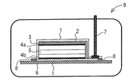
- FIG. 3 is a schematic diagram for explaining an autoclave thermocompression bonding method according to an embodiment of the present invention.
- an autoclave can be used to produce a thermoplastic liquid crystal polymer structure in which a plurality of thermoplastic liquid crystal polymer substructures are integrated.
- the thermoplastic liquid crystal polymer structure is a structure in which a plurality of thermoplastic liquid crystal polymer substructures are integrated.
- the plurality of thermoplastic liquid crystal polymer substructures may be two or more, and the required number of thermoplastic liquid crystal polymer substructures are appropriately used according to the desired shape.
- the upper limit of the number of thermoplastic liquid crystal polymer substructures is not particularly set, but may be about 1000.
- the thermoplastic liquid crystal polymer substructure comprises at least a thermoplastic liquid crystal polymer.
- thermoplastic liquid crystal polymer is composed of a melt-moldable liquid crystal polymer (or a polymer capable of forming an optically anisotropic melt phase), and the thermoplastic liquid crystal polymer is particularly preferably a melt-moldable liquid crystal polymer.
- the chemical constitution is not particularly limited, and examples thereof include a thermoplastic liquid crystal polyester, or a thermoplastic liquid crystal polyester amide having an amide bond introduced therein.
- thermoplastic liquid crystal polymer may be a polymer in which an aromatic polyester or aromatic polyester amide is further introduced with an imide bond, a carbonate bond, a bond derived from isocyanate such as a carbodiimide bond or an isocyanurate bond.
- thermoplastic liquid crystal polymer used in the present invention include known thermoplastic liquid crystal polyesters and thermoplastic liquid crystal polyester amides derived from the compounds and derivatives thereof classified into the following (1) to (4). Can be mentioned. However, it goes without saying that the combination of various raw material compounds has an appropriate range for forming a polymer capable of forming an optically anisotropic molten phase.
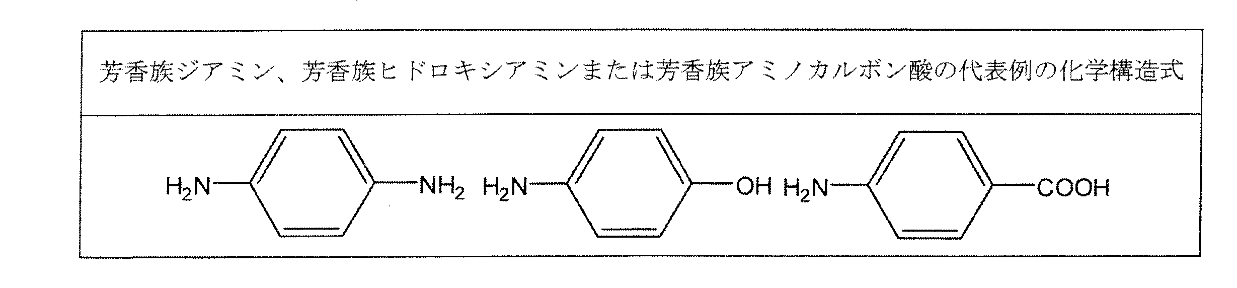
- Aromatic diamine, aromatic hydroxyamine or aromatic aminocarboxylic acid see Table 4 for representative examples.
- a polymer containing p-hydroxybenzoic acid and / or 6-hydroxy-2-naphthoic acid as at least a repeating unit is preferable, and particularly (i) p-hydroxybenzoic acid and 6-hydroxy- A polymer containing a repeating unit with 2-naphthoic acid, or (ii) at least one aromatic hydroxycarboxylic acid selected from the group consisting of p-hydroxybenzoic acid and 6-hydroxy-2-naphthoic acid, and at least one A copolymer containing a repeating unit of an aromatic diol and at least one aromatic dicarboxylic acid is preferable.
- thermoplastic liquid crystal polymer contains a repeating unit of at least p-hydroxybenzoic acid and 6-hydroxy-2-naphthoic acid
- p-hydroxybenzoic acid of the repeating unit (A) is used.
- At least one aromatic hydroxycarboxylic acid (C) selected from the group consisting of p-hydroxybenzoic acid and 6-hydroxy-2-naphthoic acid, and 4,4′-dihydroxy
- aromatic diol (D) selected from the group consisting of biphenyl, hydroquinone, phenylhydroquinone, and 4,4′-dihydroxydiphenyl ether, and selected from the group consisting of terephthalic acid, isophthalic acid, and 2,6-naphthalenedicarboxylic acid.
- the molar ratio of the repeating units derived from 6-hydroxy-2-naphthoic acid in the aromatic hydroxycarboxylic acid (C) may be, for example, 85 mol% or more, preferably 90 mol% or more, It may preferably be 95 mol% or more.
- the molar ratio of the repeating unit derived from 2,6-naphthalenedicarboxylic acid in the aromatic dicarboxylic acid (E) may be, for example, 85 mol% or more, preferably 90 mol% or more, more preferably 95 mol%. % Or more.
- the aromatic diol (D) is a repeating unit derived from two different aromatic diols selected from the group consisting of hydroquinone, 4,4′-dihydroxybiphenyl, phenylhydroquinone, and 4,4′-dihydroxydiphenyl ether.
- the ability to form an optically anisotropic molten phase in the present invention can be confirmed by, for example, placing the sample on a hot stage, heating the sample under a nitrogen atmosphere to raise the temperature, and observing the transmitted light of the sample. .
- the thermoplastic liquid crystal polymer may have a melting point (hereinafter referred to as Tm) in the range of 200 to 360 ° C., preferably in the range of 240 to 360 ° C., more preferably in the range of 260 to 360 ° C. And more preferably having a Tm of 270 to 350 ° C.
- Tm can be obtained by measuring the temperature at which the main endothermic peak appears with a differential scanning calorimeter (DSC, manufactured by Shimadzu Corporation).
- thermoplastic liquid crystal polymer within a range not impairing the effects of the present invention, a thermoplastic polymer such as polyethylene terephthalate, modified polyethylene terephthalate, polyolefin, polycarbonate, polyarylate, polyamide, polyphenylene sulfide, polyether ether ketone, fluororesin. , Various additives and fillers may be added.
- thermoplastic liquid crystal polymer film is obtained, for example, by extruding a melt-kneaded product of the thermoplastic liquid crystal polymer.
- any method may be used as the extrusion molding method, the well-known T-die method, inflation method and the like are industrially advantageous.
- stress is applied not only in the machine axis direction of the thermoplastic liquid crystal polymer film (hereinafter, abbreviated as MD direction) but also in the direction orthogonal thereto (hereinafter, abbreviated as TD direction), so that the MD direction, the TD Since it can be uniformly stretched in the direction, a thermoplastic liquid crystal polymer film in which the molecular orientation in the MD and TD directions, the dielectric properties, etc. are controlled can be obtained.
- MD direction machine axis direction of the thermoplastic liquid crystal polymer film
- TD direction direction orthogonal thereto
- the melt sheet extruded from the T-die may be stretched not only in the MD direction of the thermoplastic liquid crystal polymer film but also in both the MD direction and the TD direction to form a film.
- the melt sheet extruded from the T die may be stretched once in the MD direction and then stretched in the TD direction to form a film.
- a predetermined draw ratio (corresponding to a draw ratio in the MD direction) and a blow ratio (corresponding to a draw ratio in the TD direction) are applied to a cylindrical sheet melt-extruded from a ring die. May be stretched to form a film.
- the draw ratio of such extrusion molding may be, for example, about 1.0 to 10 as a draw ratio (or draw ratio) in the MD direction, preferably about 1.2 to 7, and more preferably 1. It may be about 3 to 7.
- the draw ratio (or blow ratio) in the TD direction may be, for example, about 1.5 to 20, preferably about 2 to 15, and more preferably about 2.5 to 14.
- thermoplastic liquid crystal polymer film may be adjusted to a desired value by, for example, the method described in JP-A-2005-103989.
- the coefficient of thermal expansion of the thermoplastic liquid crystal polymer film may be adjusted to any value in the range of ⁇ 10 ppm / ° C. to 50 ppm / ° C., for example.
- the coefficient of thermal expansion of the thermoplastic liquid crystal polymer film forming each substructure is, for example, the highest value of the coefficient of thermal expansion and the lowest value of the coefficient of thermal expansion.
- the substructures may be combined so that the coefficient of thermal expansion of the thermoplastic liquid crystal polymer film forming each substructure is different.
- the coefficient of thermal expansion of adjacent thermoplastic liquid crystal polymer films may be 15 ppm / ° C. or more, preferably 18 ppm / ° C. or more, and more preferably 20 ppm / ° C. or more.
- thermoplastic liquid crystal polymer film When forming a conductive layer (a conductive layer such as a signal layer, a power supply layer, and a ground layer, for example, a layer formed of a conductive pattern, a conductive foil, a conductive film, etc.) on a thermoplastic liquid crystal polymer film
- a conductive layer a conductive layer such as a signal layer, a power supply layer, and a ground layer, for example, a layer formed of a conductive pattern, a conductive foil, a conductive film, etc.
- the step of integrating the conductor layer and the thermoplastic liquid crystal polymer film can be performed by a known or conventional method.
- a thermoplastic liquid crystal polymer film having a conductor layer on one surface may be prepared, or a thermoplastic liquid crystal polymer film having a conductor layer on both surfaces may be prepared.
- thermocompressing a metal foil or the like to a thermoplastic liquid crystal polymer film a single-sided metal-clad laminate or a double-sided metal-clad laminate is formed, and further etching is performed as necessary to form a desired conductor layer. May be formed.
- the conductor forming the conductor layer various conductive metals such as gold, silver, copper, iron, nickel, aluminum or alloy metals thereof may be used.
- the thickness of the conductor layer can be appropriately set as necessary, and may be, for example, about 5 to 50 ⁇ m, and more preferably 8 to 35 ⁇ m.
- thermoplastic liquid crystal polymer substructure used in a thermoplastic liquid crystal polymer multilayer structure (i) a thermoplastic liquid crystal polymer film, and (ii) a thermoplastic liquid crystal polymer film having a conductor layer on one surface. , And (iii) a thermoplastic liquid crystal polymer film having conductor layers on both sides can be prepared.
- the thermoplastic liquid crystal polymer substructure may be subjected to a degassing and drying step for removing air and water present in the thermoplastic liquid crystal polymer film, prior to the temperature raising step described below.
- the degassing drying step may be performed on individual thermoplastic liquid crystal polymer substructures and combinations thereof prior to forming the pre-laminate in which the thermoplastic liquid crystal polymer substructures are superposed. It may be performed on the stack or both.
- the degassing and drying step may be performed on the thermoplastic liquid crystal polymer film prior to the step of integrating the thermoplastic liquid crystal polymer film and the conductor layer, It may be performed as part of the process of integrating the thermoplastic liquid crystal polymer film and the conductor layer.
- the degassing and drying step can improve the thermal adhesion of the thermoplastic liquid crystal polymer substructure, and can improve the interlayer adhesion of the thermoplastic liquid crystal polymer substructure.
- thermoplastic liquid crystal polymer substructure used in the degassing and drying step is not particularly limited as long as the thermoplastic liquid crystal polymer film can be degassed and dried.
- the thermoplastic liquid crystal polymer substructure may be the thermoplastic liquid crystal polymer film itself, or a thermoplastic liquid crystal film in which a conductor layer is formed on one or both surfaces of the thermoplastic liquid crystal polymer film. It may be provided as a sheet of polymer substructure. Furthermore, these thermoplastic liquid crystal polymer substructures may be provided as a roll, if desired.
- the thermoplastic liquid crystal polymer substructure may be a multilayer laminate of a plurality of thermoplastic liquid crystal polymer substructures (e.g., a multilayer laminate in which the thermoplastic liquid crystal polymer substructures are stacked in multiple layers, a temporary assembly). It may be subjected to the deaeration and drying step in the state of the above-mentioned multilayer circuit).
- thermoplastic liquid crystal polymer substructure is subjected to degassing and drying under a specific vacuum (for example, vacuum drying) and / or degassing and drying under heating (for example, heat drying), It is possible to extremely highly reduce the air and water existing inside and on the surface of the thermoplastic liquid crystal polymer film. Then, in the thermoplastic liquid crystal polymer substructure that has undergone such a degassing and drying step, it is possible to improve its thermal adhesiveness.
- a specific vacuum for example, vacuum drying
- degassing and drying under heating for example, heat drying
- thermoplastic liquid crystal polymer film that has been subjected to a degassing and drying process, it is possible to achieve high adhesion without performing a softening treatment such as breaking the skin layer. However, the softening process is not denied.
- the thermoplastic liquid crystal polymer film may be subjected to surface treatment such as softening treatment, if necessary.
- the thermoplastic liquid crystal polymer substructure is (a) degassed and dried under vacuum at a vacuum degree of 1500 Pa or less for 30 minutes or more, and / or (b) in the range of 80 ° C to 300 ° C.
- the thermoplastic liquid crystal polymer film can be degassed and dried by being degassed and dried under heating.
- the degassing and drying may be performed under the conditions satisfying either (a) the degassing and drying step under vacuum or (b) the degassing and drying step under heating. ) And (b), it is preferable to perform degassing and drying under the conditions.
- Degassing and drying under the conditions satisfying both (a) and (b) means degassing and drying performed under conditions where both (a) and (b) are simultaneously satisfied (that is, under vacuum heating).
- Step, or a degassing and drying step in which the conditions (a) and (b) are separately applied to the thermoplastic liquid crystal polymer substructure, that is, in the order of (a) to (b), or (b) ) To (a) may be separately performed in the degassing and drying step.
- thermoplastic liquid crystal polymer film is not adversely affected.
- a separate drying step may be performed.
- degassing and drying may be performed under no pressure (pressure is released) without substantially applying pressure.
- the degassing and drying step is performed under low pressurization or pressure release (for example, under a pressure of about 0 to 0.7 MPa (gauge pressure), preferably under a pressure of about 0 to 0.5 MPa (gauge pressure)). Good.
- Deaeration and drying under vacuum may be performed at a vacuum degree of 1500 Pa or less, preferably 1300 Pa or less, and more preferably 1100 Pa or less.
- the degassing and drying under vacuum may be carried out independently, it may be carried out at room temperature (for example, in the range of 10 to 50 ° C., preferably 15 to 45 ° C.), but under heating from the viewpoint of enhancing the degassing and drying efficiency. You may go in.
- the heating temperature may be, for example, 50 to 300 ° C. (for example, 50 to 250 ° C.), preferably 80 to 250 ° C., and more preferably about 80 to 200 ° C.
- (B) Degassing and drying under heating may be performed in the range of 80 to 300 ° C, preferably in the range of 80 to 250 ° C, and more preferably in the range of 80 to 200 ° C. Further, in the degassing and drying under heating, a predetermined temperature range may be set with respect to the melting point Tm of the thermoplastic liquid crystal polymer or the thermoplastic liquid crystal polymer film. In that case, for example, heating may be performed in the range of (Tm-235) ° C. to (Tm-10) ° C. (eg, the range of (Tm-200) ° C. to (Tm-50) ° C.), and preferably, (Tm-225) ° C. to (Tm-50) ° C.
- thermoplastic liquid crystal polymer film may be, for example, 270 to 380 ° C., preferably 280 to 370 ° C.
- moisture in the film (such as the inside of the film or the film surface) can be degassed and dried while suppressing the sudden generation of water.
- moisture in the film such as the inside of the film or the film surface
- the deaeration and drying under heating When the deaeration and drying under heating is carried out alone, it may be carried out under the condition that the degree of vacuum is not more than 1500 Pa, for example, it may be carried out under the atmospheric pressure (or normal pressure) where the pressure is not adjusted. However, if necessary, the heating may be performed under a condition where the atmospheric pressure is reduced (for example, more than 1500 Pa and less than 100,000 Pa, preferably about 3,000 to 50,000 Pa).
- the time required for the degassing and drying step can be appropriately set depending on various conditions such as the state of the thermoplastic liquid crystal polymer film in the thermoplastic liquid crystal polymer substructure, the degree of vacuum and / or the heating temperature. From the viewpoint of removing water and air from the whole, for example, in each degassing and drying step (under vacuum, under heating, under vacuum heating), the same or different, 30 minutes or more, 40 minutes or more, or 50 minutes or more 6 hours or less, 4 hours or less, 3 hours or less, 2 hours or less, or 1.5 hours or less.
- the time required for the degassing and drying step may be appropriately set, for example, in consideration of the time when the water content of the thermoplastic liquid crystal polymer film falls within a predetermined range (for example, 380 ppm or less, 300 ppm or less, or 200 ppm or less). Good.
- the thermal adhesiveness of the thermoplastic liquid crystal polymer substructure is improved.
- the order of (a) degassing and drying under vacuum and (b) degassing and drying under heating may be either first, but preferably, heating is performed as the first degassing and drying step. After performing deaeration and drying under vacuum, deaeration and drying under vacuum may be performed as a second deaeration and drying step.
- the first degassing / drying step in which the degassing / drying is performed by heating in the range of 80 ° C. to 300 ° C. for a predetermined time, and the degree of vacuum is 1500 Pa or less
- a second degassing and drying step of performing degassing and drying for a period of time when performing these deaeration and drying steps, the above-mentioned conditions can be combined as appropriate.
- thermoplastic liquid crystal polymer structure An integrated thermoplastic liquid crystal polymer structure can be produced by thermocompressing a preliminary laminate obtained by laminating a plurality of thermoplastic liquid crystal polymer substructures using an autoclave.
- thermoplastic liquid crystal polymer substructure is laminated with a pre-laminate is covered with a bagging film, an enclosing step of sealing the end portion of the bagging film, and exhausting the inside of the bagging film, A temperature raising step of raising the temperature to a first temperature which is a preheating temperature, and increasing the internal pressure of the autoclave to a desired pressure of 2.8 MPa or less (gauge pressure) from the first temperature as a starting point and thermocompression bonding temperature. And a thermocompression bonding step of raising the temperature to the second temperature.
- a preliminary laminate in which a plurality of thermoplastic liquid crystal polymer substructures are superposed is prepared, and after the preliminary laminate is covered with a bagging film (preferably after being wrapped), an end portion of the bagging film is prepared. Seal.
- the laminated structure of the preliminary laminated body is appropriately determined according to the application.
- the bagging film is not particularly limited as long as it can cover the preliminary laminate and can withstand the autoclave heating conditions, and even if it is a single layer, it is a multilayer in which a plurality of materials are combined in layers. Good.
- the bagging film may be, for example, a heat resistant polymer film (for example, a polyimide film or a fluorine-based film) or a composite material of a metal and a heat resistant polymer film.
- a heat resistant polymer film for example, a polyimide film or a fluorine-based film
- a composite material of a metal and a heat resistant polymer film for example, a heat resistant polymer film.
- the pre-laminate may be directly covered with a bagging film, and from the viewpoint of improving exhaust, a release material, a metal plate, a breathable sheet or the like may be appropriately interposed between the pre-laminate and the bagging film. Good.
- other components for example, a release material, a metal plate, a breathable sheet, etc. may be covered or wrapped with the bagging film.
- the release agent is not particularly limited as long as it is a material having releasability with respect to the thermoplastic liquid crystal polymer.
- a polyimide film, a fluorine-based film (for example, polytetrafluoroethylene film), a release multilayer composite for example, a first metal foil, a pair of high-density polyethylene sheets whose MD directions are orthogonal to each other, a second metal foil, and a low friction film
- the first and second metal foils may be preferably aluminum foils
- the low-friction film has a static friction coefficient of 0.30 or less (preferably 0.05) defined by JIS K 7125. It may be a film having a low friction coefficient of about 0.25), specifically, an ultra high molecular weight polyethylene film, a polytetrafluoroethylene film, or the like.
- the breathable sheet is not particularly limited as long as it is made of a heat-resistant porous material, but, for example, a glass cloth, a heat-resistant fiber cloth, or a metal mesh sheet-like material can be used.
- an appropriate metal plate may be interposed between the preliminary laminate and the breathable sheet.
- the metal constituting the metal plate for example, a known or commonly used metal material having high compression resistance can be used, and stainless steel is preferable.
- the metal plate may have a thickness of, for example, about 0.1 mm to 1 cm, preferably about 0.2 mm to 0.8 mm, and more preferably about 0.3 mm to 0.6 mm.
- the ends of the bagging film are sealed to exhaust the inside of the bagging film.
- sealing the end portion there is no particular limitation as long as the opposite end portion of the bagging film can be sealed, and the end portion may be sealed with a sealing means such as tape, or by pressing with a jig such as a vise. It is also possible to seal them by combining them.
- Temperature raising step In the temperature raising step, the inside of the bagging film is exhausted and the temperature is raised to the first temperature which is the preheating temperature.
- the exhaust mechanism inside the bagging film is not particularly limited as long as the exhaust is possible, but for example, after the end portion of the bagging film is sealed, the inside of the bagging film is exhausted.
- the temperature may be raised before the exhaust of the bagging film, overlapping with the exhaust, or after the exhaust.
- preheating may be performed by maintaining the first temperature for a predetermined time. Until the preheating, it is preferable that the pressurized gas is not positively pressurized inside the autoclave.
- the first temperature is the preheating temperature.
- the thermoplastic liquid crystal polymer molecules do not have a vigorous fluidity.
- the first temperature is, for example, (ML-150) ° C. to (ML-50) when the melting point of the thermoplastic liquid crystal polymer element to be preheated in forming the pre-laminate is ML. ) ° C., preferably (ML-130) ° C. to (ML-70) ° C.
- the thermoplastic liquid crystal polymer element to be preheated may be the thermoplastic liquid crystal polymer element having the lowest melting point in the preliminary laminate.
- the first temperature can be appropriately set according to the flow starting temperature of the thermoplastic liquid crystal polymer, but may be, for example, in the range of 150 to 250 ° C, preferably about 180 to 230 ° C. May be.
- the temperature raising rate in the temperature raising step may be, for example, 1 to 10 ° C./min, and preferably 2 to 8 ° C./min.
- the holding time at the first temperature is not particularly limited as long as thermocompression bonding between the layers of the preliminary laminate is performed, and may be appropriately changed depending on the presence or absence of degassing treatment and the preheating temperature.
- the holding time (or preheating time) at the temperature may be, for example, about 1 to 120 minutes, preferably about 3 to 60 minutes.
- a predetermined holding time (or preheating time) at the first temperature has passed, for example, the water content of the thermoplastic liquid crystal polymer element to be preheated is within a predetermined range (for example, 380 ppm or less, 300 ppm or less, Or 200 ppm or less).
- the holding time at the first temperature may be about 1 to 20 minutes, preferably about 2 to 15 minutes, more preferably 2 to 10 minutes. It may be done to some extent.
- thermocompression bonding process In the thermocompression bonding process, starting from the first temperature, the internal pressure of the autoclave is increased to a desired pressure of 2.8 MPa or less (gauge pressure), and the temperature is increased to the second temperature, which is the thermocompression bonding temperature, to perform preliminary lamination. Thermocompression bonding between layers of the body is performed.
- the temperature rising rate may be 2 to 20 ° C./min, preferably 3 to 15 ° C./min, and more preferably 4 to 10 ° C./min.
- the second temperature may be the maximum heating temperature, by which the thermoplastic liquid crystal polymer substructure in the pre-laminate is thermocompression bonded. The laminate of the thermoplastic liquid crystal polymer substructure is then cooled and, after releasing the pressure, can be obtained as a thermoplastic liquid crystal polymer structure.
- the maximum pressure in the autoclave needs to be 2.8 MPa or less (gauge pressure), preferably 2.5 MPa or less (gauge pressure), More preferably, it may be 2 MPa or less (gauge pressure).
- the lower limit of the maximum pressure is not particularly limited as long as it can bond the thermoplastic liquid crystal polymer substructure, but may be, for example, 1.5 MPa (gauge pressure).
- the second temperature is the thermocompression bonding temperature.
- the thermocompression bonding temperature is not limited as long as it is a range in which either one of the adjacent substructures can be fused between the thermoplastic liquid crystal polymer elements of the thermoplastic liquid crystal polymer substructure.
- the thermocompression bonding temperature may be determined after grasping the heat fusion temperature of the thermoplastic liquid crystal polymer substructure in advance.
- the second temperature is, for example, in the range of (MH-30) ° C to (MH + 10) ° C.
- the temperature may be about (MH-10) ° C to (MH + 5) ° C.
- the thermoplastic liquid crystal polymer element to be fused may be the thermoplastic liquid crystal polymer element having the highest melting point in the preliminary laminate.
- the holding time (or thermocompression bonding time) at the second temperature is not particularly limited as long as thermocompression bonding between layers of the preliminary laminate is performed, and may be appropriately changed depending on the presence or absence of degassing / drying treatment and the thermocompression bonding temperature. Although it is possible, for example, it may be carried out for about 15 to 60 minutes, preferably about 20 to 50 minutes, more preferably about 20 to 40 minutes.
- thermoplastic liquid crystal polymer substructures With such a manufacturing method, it is possible to achieve good adhesion between adjacent thermoplastic liquid crystal polymer substructures while suppressing a rapid flow of the thermoplastic liquid crystal polymer molecules.
- thermoplastic liquid crystal polymer structure using an autoclave
- FIG. 1 shows a schematic diagram for explaining an autoclave thermocompression bonding method according to an embodiment of the present invention.
- a pre-laminate 5 is placed on the carrier plate 6 which is wrapped with the bagging film 1 and in which a plurality of thermoplastic liquid crystal polymer substructures are superposed in a desired configuration.
- the release materials 4a and 4b are arranged on the upper and lower surfaces of the preliminary laminate 5, and the breathable sheet 2 with the top plate 3 interposed on the release material 4a on the upper surface. Is provided.
- the bagging film 1 is sealed with a vacuum sealant tape 8, and a vacuum nozzle 7 for vacuuming is connected to an appropriate portion of the bagging film 1.
- the air inside the bagging film 1 is exhausted by the vacuum nozzle 7.
- a breathable sheet 2 may be provided inside the bagging film 1 if necessary. The presence of the breathable sheet 2 can further enhance the exhaustability of the inside of the bagging film 1.
- the breathable sheet 2 is arranged so as to communicate with the vacuum nozzle 7 from above the preliminary laminate 5 to the side of the preliminary laminate 5.
- the place where the breathable sheet 2 is set is not limited as long as the exhaust property can be enhanced around the preliminary laminate 5.
- the breathable sheet 2 may be arranged in at least one place selected from above, below, and laterally of the preliminary laminate 5.
- the bagging film 1 is provided both above and below the preliminary laminate 5, and is sealed at the end with a vacuum sealant tape 8 to cover the preliminary laminate 5 in a packed state. There is.
- the bagging film 1 below does not have to be provided.
- the preliminary laminate 5 is covered with a bagging film 1 from above, and the end portion of the bagging film 1 is sealed to the carrier plate 6 by using a predetermined sealing means (for example, tape such as vacuum sealant tape). Good.
- a predetermined sealing means for example, tape such as vacuum sealant tape.
- the sealing means and the polyimide film may be pressed by a jig such as a vise.
- a pressurized gas is supplied from the gas source (not shown) into the autoclave 9. Since the supplied pressurized gas is uniformly present around the bagging film 1, it is possible to uniformly pressurize the inside of the bagging film 1.
- the pressure applied to the bagging film 1 is applied to the laminated body 5 as it is.
- the pre-laminate 5 is subjected to equal pressure not only from the upper and lower surfaces, but also from the side faces thereof, so that the thermoplastic liquid crystal polymer substructures inside the pre-laminate 5 can be adhered to each other.
- the bagging film 1 is not particularly limited as long as it is a flexible material having heat resistance and pressure resistance, and examples thereof include a polyimide film.
- the release materials 4a and 4b for example, a polyimide film, a fluorine-based film, a release multilayer composite material, or the like is used.
- the breathable sheet 2 is not particularly limited as long as it can be used to exhaust the air existing between the bagging film 1 and the pre-laminate 5, but, for example, glass cloth, heat resistant fiber cloth, or A metal mesh sheet-like material or the like can be used.
- the metal plate is arranged to prevent the shape derived from the breathable sheet 2 from being reflected on the surface of the thermoplastic liquid crystal polymer structure. Therefore, if the breathable sheet 2 is not provided, the metal plate may not be provided.
- the pressurized gas is not particularly limited as long as it is a gas that has high reactivity under heating, and may be normal air or the like, but nitrogen gas or the like may be appropriately used.
- thermoplastic liquid crystal polymer substructures can be bonded to each other while suppressing excessive flow of the thermoplastic liquid crystal polymer molecules by performing specific heating conditions in the autoclave thermocompression bonding method. Further, since the flow of the thermoplastic liquid crystal polymer molecules can be made gentle, the orientation of the thermoplastic liquid crystal polymer structure can be made uniform and the integrity of the thermoplastic liquid crystal polymer structure can be enhanced. Further, when a circuit formed of a conductor pattern exists, it is possible to make the flow of the thermoplastic liquid crystal polymer in the vicinity of the circuit slow and to make the orientation of the thermoplastic liquid crystal polymer uniform even if the circuit exists. it can.
- the preliminary laminate is pressed under a desired pressure of 2.8 MPa or less (gauge pressure) to perform thermocompression bonding.
- thermoplastic liquid crystal polymer structure The resulting thermoplastic liquid crystal polymer structure has excellent integrity of the thermoplastic liquid crystal polymer substructure, and the generation of resin flow resulting from excessive flow of the thermoplastic liquid crystal polymer molecules that form the structure during the manufacturing process. Can be suppressed.
- thermoplastic liquid crystal polymer structure of the present invention is obtained by integrating a plurality of thermoplastic liquid crystal polymer substructures using an autoclave so that the coefficient of thermal expansion of the thermoplastic liquid crystal polymer element of each substructure after lamination has a predetermined value. Or the coefficient of thermal expansion of the thermoplastic liquid crystal polymer film may be adjusted in advance before forming the thermoplastic liquid crystal polymer structure.
- the thermal expansion coefficient of the thermoplastic liquid crystal polymer element is determined by the thermoplastic liquid crystal polymer structure. It may be judged to be the same as the coefficient of thermal expansion of the thermoplastic liquid crystal polymer film used in each of the constituent thermoplastic liquid crystal polymer substructures.
- the coefficient of thermal expansion in the plane direction of the thermoplastic liquid crystal polymer element in the thermoplastic liquid crystal polymer structure may be, for example, -10 ppm / ° C to 50 ppm / ° C, preferably 10 ppm / ° C to 50 ppm / ° C. , And more preferably in the range of 15 ppm / ° C. to 45 ppm / ° C.
- the coefficient of thermal expansion in the plane direction of the thermoplastic liquid crystal polymer element in the thermoplastic liquid crystal polymer structure is determined by a predetermined thickness (for example, in the range of 10 to 100 ⁇ m, maximum value) for each of the front surface and the back surface of the thermoplastic liquid crystal polymer structure. When the laminated state of the thermoplastic liquid crystal polymer layer of the outer layer is clear, it may be evaluated by a value obtained by collecting the thermoplastic liquid crystal polymer element (thickness thereof).
- the tolerance of the coefficient of thermal expansion in the plane direction of the thermoplastic liquid crystal polymer element in the thermoplastic liquid crystal polymer structure is, for example, 50 ppm / ° C or less, 40 ppm / ° C or less, 30 ppm / ° C or less, 20 ppm / ° C, depending on the application. It may be the following, 15 ppm / ° C or less, 10 ppm / ° C or less, 5 ppm / ° C or less, 3 ppm / ° C or less, or 1 ppm / ° C or less.
- the tolerance of the coefficient of thermal expansion in the surface direction of the thermoplastic liquid crystal polymer element in the thermoplastic liquid crystal polymer structure is obtained by randomly sampling a plurality of thermoplastic liquid crystal polymer elements as sample pieces from the thermoplastic liquid crystal polymer structure.
- the difference between the maximum value and the minimum value of the coefficient of thermal expansion in the surface direction of the sample piece may be, but from the viewpoint of simplicity, a predetermined thickness (for each of the front surface and the back surface of the thermoplastic liquid crystal polymer structure) ( For example, a thermoplastic liquid crystal polymer element having a thickness in the range of 10 to 100 ⁇ m and a thickness of the outermost thermoplastic liquid crystal polymer layer (when it is clear) may be sampled, and the difference in the coefficient of thermal expansion in the plane direction may be used as the tolerance.
- thermoplastic liquid crystal polymer substructure is preferably (i) a thermoplastic liquid crystal polymer layer, (ii) a thermoplastic liquid crystal polymer layer having a conductor layer on one surface, and (iii) It may be composed of at least two thermoplastic liquid crystal polymer substructures selected from the group consisting of thermoplastic liquid crystal polymer layers having conductor layers on both sides.
- thermoplastic liquid crystal polymer substructure it is possible to use substructures of various shapes as long as they are formed from the thermoplastic liquid crystal polymer and a plurality of substructures can be integrated.
- the thermoplastic liquid crystal polymer substructure comprises (i) a thermoplastic liquid crystal polymer layer alone (L), (ii) a thermoplastic liquid crystal polymer layer (CL) having a conductor layer on one surface, and (iii) a conductor layer.
- CLC thermoplastic liquid crystal polymer layers
- the conductor layer is a layer having conductivity, and examples thereof include a signal layer, a power supply layer, and a ground layer. Specifically, a layer formed of a conductor pattern, a conductor foil, a conductor film, or the like. The conductor layer may be formed in a desired shape as needed.
- thermoplastic liquid crystal polymer substructures include, for example, the following combinations.
- L a thermoplastic liquid crystal polymer layer alone
- CL a thermoplastic liquid crystal polymer layer having a conductor layer on one surface
- CLC thermoplastic liquid crystal polymer layer having a conductor layer on both surfaces.
- the thickness of the thermoplastic liquid crystal polymer film (thermoplastic liquid crystal polymer layer after thermocompression bonding) constituting the thermoplastic liquid crystal polymer substructure can be appropriately set according to the application, but is preferably 140 ⁇ m or less for all. It may be present, more preferably 120 ⁇ m or less, and further preferably 110 ⁇ m or less.
- the lower limit of the thickness of the thermoplastic liquid crystal polymer film (or the thermoplastic liquid crystal polymer layer) may be about 10 ⁇ m, but depending on the target thickness, it is 15 ⁇ m or more, 30 ⁇ m or more, 60 ⁇ m or more, or 85 ⁇ m. It may be more than.
- the thickness of the thermoplastic liquid crystal polymer film (or the thermoplastic liquid crystal polymer layer) forming each sub-structure may be the same or different, but the same degree (for example, the difference between the thicknesses is 10% or less, preferably Is 5% or less).
- the number of thermoplastic liquid crystal polymer substructures can be appropriately set according to the application.
- the number of thermoplastic liquid crystal polymer substructures is, for example, about 2 to 10, preferably 3 to 8. It may be a degree.
- the thickness of each thermoplastic liquid crystal polymer substructure may be about 10 to 70 ⁇ m, preferably about 10 to 60 ⁇ m.
- the thickness of the thermoplastic liquid crystal polymer structure may be 30 ⁇ m or more, 50 ⁇ m or more, 100 ⁇ m or more.
- the upper limit of the thickness can be set as appropriate, but may be, for example, 150 ⁇ m or less.
- the number of the thermoplastic liquid crystal polymer substructures is, for example, 2 or more and 3 or more depending on the thickness required for the thermoplastic liquid crystal polymer substructure or the thickness of the thermoplastic liquid crystal polymer substructure when used for thick applications. It may be 4 or more, 9 or more, or 10 or more.
- the upper limit is not particularly limited, but may be, for example, 200 or less, 150 or less, 100 or less, 50 or less, 20 or less, or 15 or less. Note that the descriptions regarding the upper limit and the lower limit can be freely combined. In that case, the thickness of each thermoplastic liquid crystal polymer substructure may be about 50 to 140 ⁇ m, preferably about 70 to 120 ⁇ m.
- the thermoplastic liquid crystal polymer structure may be greater than 150 ⁇ m, 250 ⁇ m or greater, 350 ⁇ m or greater, 450 ⁇ m or greater, or 550 ⁇ m or greater.
- the upper limit of the thickness can be set as appropriate, but may be 5 mm or less, for example.
- thermoplastic liquid crystal polymer elements of each thermoplastic liquid crystal polymer substructure constituting the thermoplastic liquid crystal polymer structure may have the same or different melting points. If different, the temperature difference between the thermoplastic liquid crystal polymer element having the lowest melting point and the thermoplastic liquid crystal polymer element having the highest melting point is more than 0 ° C. and 100 ° C. or less, preferably 10 ° C. or more and 90 ° C. Hereafter, it may be 20 ° C. or higher and 80 ° C. or lower.
- the thermoplastic liquid crystal polymer structure may have three or more conductor layers (for example, a metal foil layer or a conductor pattern made of a metal foil). Further, depending on the use, it may have 5 or more conductor layers, or 7 or more conductor layers.
- the upper limit of the conductor layer is not particularly limited, but may be about 20 layers.
- thermoplastic liquid crystal polymer structure When the thermoplastic liquid crystal polymer structure is a laminate of the thermoplastic liquid crystal polymer substructure composed of the thermoplastic liquid crystal polymer layer, the thermoplastic liquid crystal polymer structure of the present invention has excellent integrity, It has thermocompression bonding properties between the thermoplastic liquid crystal polymer substructures.
- thermocompression bonding property or adhesive property means that the adhesive strength evaluated by the method described in Examples described later is, for example, 0.4 N / mm or more, preferably 0.5 N / mm or more.
- the structure can be integrated by thermocompression bonding, and the adhesive strength between adjacent sub-structures can be increased, which is preferable.
- thermoplastic liquid crystal polymer structure having excellent isotropy
- the degree of molecular orientation SOR of the thermoplastic liquid crystal polymer structure is, for example, 0.95 to 1.25. It may be about, preferably about 0.98 to 1.18.
- the degree of molecular orientation SOR of the thermoplastic liquid crystal polymer structure is a value measured by the method described in Examples below.
- the difference in the coefficient of thermal expansion in the plane direction of each thermoplastic liquid crystal polymer element in the adjacent thermoplastic liquid crystal polymer substructure may be, for example, 15 ppm / ° C. or more, and preferably 18 ppm / ° C. or more. And more preferably 20 ppm / ° C. or higher.
- thermoplastic liquid crystal polymer structure of the present invention can be combined with various thermoplastic liquid crystal polymer substructures to obtain a three-dimensional three-dimensional structure such as a plate or a two-dimensional three-dimensional structure such as a rod.
- the structure has high integrity, and excessive flow of molecules inside the structure is suppressed.
- the thermoplastic liquid crystal polymer structure of the present invention can be effectively used as a component used in the fields of electric / electronics, office equipment, precision equipment, and the like.
- a multilayer circuit board especially a board for millimeter wave radar).
- a power module, etc. can be usefully used.
- thermomechanical analyzer TMA-60 manufactured by Shimadzu Corporation. After increasing the temperature from room temperature to 200 ° C. at a rate of 5 ° C./minute, cooling to 30 ° C. at a rate of 20 ° C./minute, and increasing the temperature at a rate of 5 ° C./minute to 30 ° C. and 150 ° C. It was calculated based on the change in the length.
- thermoplastic liquid crystal polymer element in the thermoplastic liquid crystal polymer structure The coefficient of thermal expansion in the plane direction of the thermoplastic liquid crystal polymer element in the thermoplastic liquid crystal polymer structure is a typical value.
- the outermost thermoplastic liquid crystal polymer layer is peeled off, and the obtained two layers are respectively separated. It was regarded as a thermoplastic liquid crystal polymer film. Then, each layer was measured by the same method as the measurement of the thermal expansion coefficient of the thermoplastic liquid crystal polymer film as described above.
- thermoplastic liquid crystal polymer element for each coefficient of thermal expansion of the obtained two layers, one is the maximum value and the other is the minimum value, The difference was taken as the tolerance for the coefficient of thermal expansion of the thermoplastic liquid crystal polymer element.
- thermocompression bonding property According to JIS C5016-1994, at a speed of 50 mm / min, one of the adjacent thermoplastic liquid crystal polymer films is peeled in the direction of 90 ° from the other while being pulled by a tensile tester (made by Imada Co., Ltd.). The peeling strength was measured with a digital force gauge ZTS-500N), and the obtained value was taken as the adhesive strength. The thermocompression bonding property was determined by confirming that the lower limit of the adhesive strength, which does not cause a problem in practical use in which adjacent thermoplastic liquid crystal polymer substructures are not separated from each other, is 0.4 N / mm, and then determines the adjacent thermoplastic liquid crystal polymer.
- the adhesive strength between the sub-structures was 0.4 N / mm or more, the adhesiveness was considered good, and it was judged to be within the acceptable range.
- one direction (MD direction) of the thermoplastic liquid crystal polymer film and a direction (TD direction) orthogonal thereto are peeled off from both sides, respectively, so that the MD forward direction (or MD advancing direction) and the MD reverse direction (or Adhesive strength was measured in four directions: MD non-advancing direction), TD forward direction (or TD rightward direction), and TD reverse direction (or TD leftward direction), and the average value thereof was representative of the adhesive strength between thermoplastic liquid crystal polymer films. Value. Further, the adhesive strength was evaluated by peeling the two layers that were randomly selected and in contact with each other, and evaluated the strength.
- thermoplastic liquid crystal polymer structure A sample was cut out from the thermoplastic liquid crystal polymer structure to the extent that it could be inserted into a microwave resonant waveguide.
- a sample was prepared without cutting out a section.
- a microwave molecular orientation measuring instrument a sample is inserted into a microwave resonant waveguide so that the sample surface is perpendicular to the traveling direction of the microwave, and the electric field strength (microwave) of the microwave transmitted through the sample is measured. Wave transmission intensity) is measured. Then, based on this measured value, the m value (referred to as the refractive index) is calculated by the following equation.
- m (Zo / ⁇ z) X [1- ⁇ max / ⁇ o]
- Zo is the device constant
- ⁇ z is the average thickness of the object
- ⁇ max is the frequency that gives the maximum microwave transmission intensity when the microwave frequency is changed
- ⁇ o is when the average thickness is zero (that is, when the object is It is the frequency that gives the maximum microwave transmission intensity (when there is no).
- the degree of molecular orientation SOR was calculated by m0 / m90, where m0 is the m value when the directions are matched and m90 is the m value when the rotation angle is 90 °.
- thermoplastic liquid crystal polymer substructure As a thermoplastic liquid crystal polymer substructure, a thermoplastic liquid crystal polymer film (Bakster (registered trademark) manufactured by Kuraray Co., Ltd.) having a melting point of 310 ° C., a thermal expansion coefficient of 18 ppm / ° C. and a thickness of 18 ⁇ m is used, and three substructures are stacked. A preliminary laminated body was put together, and this preliminary laminated body was subjected to thermocompression bonding using an autoclave (AC-1200 ⁇ 2100 manufactured by Ashida Manufacturing Co., Ltd.).
- an autoclave AC-1200 ⁇ 2100 manufactured by Ashida Manufacturing Co., Ltd.
- a preliminary laminate was sandwiched between release sheets, and a metal plate and a breathable sheet (glass cloth) were placed on the upper and lower surfaces of the laminate and placed on a carrier plate. Then, the entire object is covered with a bagging film (polyimide film), and the ends of the bagging film are sealed with a sealing material (vacuum sealant tape GS-8003-G manufactured by AIRTECH) to seal the whole as a sample bag. did.
- the air inside the bagging film is exhausted by the vacuum nozzle, and a breathable sheet is also provided on the side surface of the mounting plate in order to improve the exhaust to the vacuum nozzle.
- thermocompression bonding was performed by an autoclave while measuring the actual temperature of the sample.
- the inside of the sample bag was evacuated, and then the temperature was raised to the first temperature of 200 ° C.
- the heating rate was 5 ° C./min.
- the film was preheated by holding it at 200 ° C. for 30 minutes so that the water content of the film was 100 ppm or less, and then the internal pressure of the autoclave was gradually increased from atmospheric pressure to 2 MPa (gauge pressure).
- the temperature was raised to the second temperature of 300 ° C. and kept for 30 minutes. Cooling was performed at 6 ° C./min.
- thermoplastic liquid crystal polymer element The thermal expansion coefficient of the outermost layer of the thermoplastic liquid crystal polymer element as a representative value was 18 ppm / ° C. on each of the front surface and the back surface. Further, the coefficient of thermal expansion of the thermoplastic liquid crystal polymer element present in the center was also measured, and the coefficient of thermal expansion was 18 ppm / ° C.
- the SOR of the thermoplastic liquid crystal polymer structure was 1.02.
- Example 2 A thermoplastic liquid crystal polymer structure was obtained in the same manner as in Example 1 except that a conductive pattern was formed on one surface of the thermoplastic liquid crystal polymer film of Example 1 as the thermoplastic liquid crystal polymer substructure.
- the thermal expansion coefficient of the outermost layer of the thermoplastic liquid crystal polymer element as a representative value was 18 ppm / ° C. on each of the front surface and the back surface.
- As the conductor pattern a copper foil CF-H9A-DS-HD2-12 (manufactured by Fukuda Metal Foil & Powder Co., Ltd.) was used, and a vacuum batch press (Kitagawa Seiki Co., Ltd. product name: VH2-1600) was used. And laminated at 290 ° C. and 2 MPa (gauge pressure), and then a copper foil pattern was formed by etching.
- thermoplastic liquid crystal polymer substructure a thermoplastic liquid crystal polymer structure was prepared in the same manner as in Example 1 except that six thermoplastic liquid crystal polymer films having a melting point of 310 ° C. and a thickness of 100 ⁇ m were used and the heating temperature was 310 ° C.
- the thermal expansion coefficient in the surface direction of the thermoplastic liquid crystal polymer element of the outermost layer as a typical value was 20 ppm / ° C on each of the front surface and the back surface.
- thermoplastic liquid crystal polymer structure was obtained in the same manner as in Example 3 except that the thermoplastic liquid crystal polymer substructure used was one in which a conductor pattern was formed on one surface of the thermoplastic liquid crystal polymer film of Example 3.
- the thermal expansion coefficient in the surface direction of the thermoplastic liquid crystal polymer element of the outermost layer as a typical value was 20 ppm / ° C on each of the front surface and the back surface.
- As the conductor pattern a copper foil CF-H9A-DS-HD2-12 (manufactured by Fukuda Metal Foil & Powder Co., Ltd.) was used, and a vacuum batch press (Kitagawa Seiki Co., Ltd. product name: VH2-1600) was used. And laminated at 290 ° C. and 2 MPa (gauge pressure), and then a copper foil pattern was formed by etching.
- thermoplastic liquid crystal polymer structure was obtained in the same manner as in Example 1 except that 12 thermoplastic liquid crystal polymer films each having a melting point of 310 ° C. and a thickness of 100 ⁇ m were used as the thermoplastic liquid crystal polymer substructure.
- the thermal expansion coefficient of the outermost layer of the thermoplastic liquid crystal polymer element as a representative value was 18 ppm / ° C. on each of the front surface and the back surface.
- thermoplastic liquid crystal polymer structure was obtained in the same manner as in Example 5 except that the pressure during thermocompression bonding was 1 MPa (gauge pressure).
- the thermal expansion coefficient of the outermost layer of the thermoplastic liquid crystal polymer element as a representative value was 18 ppm / ° C. on each of the front surface and the back surface.
- thermoplastic liquid crystal polymer structure was obtained in the same manner as in Example 1 except that 100 thermoplastic liquid crystal polymer films having a melting point of 310 ° C. and a thickness of 100 ⁇ m were used as the thermoplastic liquid crystal polymer substructure.
- the thermal expansion coefficient of the outermost layer of the thermoplastic liquid crystal polymer element as a representative value was 18 ppm / ° C. on each of the front surface and the back surface.
- thermoplastic liquid crystal polymer structure was obtained in the same manner as in Example 1 except that two thermoplastic liquid crystal polymer films each having a melting point of 310 ° C. and a thickness of 100 ⁇ m having different thermal expansion coefficients were used as the thermoplastic liquid crystal polymer substructure. .
- the thermal expansion coefficient of each thermoplastic liquid crystal polymer film was 10 ppm / ° C and 30 ppm / ° C.
- the laminated structure had a so-called bimetal characteristic that its shape was changed by temperature change. That is, the obtained laminate has a warp immediately after being laminated, and even if the warp is mechanically flattened by hot pressing, the shape changes again due to temperature change and bends toward the low thermal expansion coefficient side. Had characteristics.
- thermoplastic liquid crystal polymer structure was obtained in the same manner as in Example 3 except that the heating temperature during thermocompression bonding was 260 ° C. and the pressure was 1 MPa (gauge pressure).
- the thermal expansion coefficient of the outermost layer of the thermoplastic liquid crystal polymer element as a representative value was 18 ppm / ° C. on each of the front surface and the back surface.
- thermoplastic liquid crystal polymer substructure is degassed and dried at 200 ° C. for 60 minutes by using a hot air oven to reduce the water content to 100 ppm or less and then used as a preliminary laminate, and the temperature rising rate in the preliminary heating is 20 ° C./min.
- a thermoplastic liquid crystal polymer structure was obtained in the same manner as in Example 3 except that the holding time was changed to 5 minutes.
- the thermal expansion coefficient in the surface direction of the thermoplastic liquid crystal polymer element of the outermost layer as a typical value was 20 ppm / ° C on each of the front surface and the back surface.
- thermoplastic liquid crystal polymer films having a melting point of 310 ° C. and a thickness of 100 ⁇ m are stacked and vacuum 4 torr, 260 ° C., 4 MPa (gauge pressure) using a vacuum batch press (trade name: VH2-1600 manufactured by Kitagawa Seiki Co., Ltd.). ) For 30 minutes.
- thermoplastic liquid crystal polymer structure was obtained in the same manner as in Comparative Example 1 except that the temperature during thermocompression bonding was 290 ° C.
- thermoplastic liquid crystal polymer structure was obtained in the same manner as in Comparative Example 1 except that the temperature during thermocompression bonding was 310 ° C. and the pressure was 2 MPa (gauge pressure).
- thermoplastic liquid crystal polymer films each having the conductor pattern formed on one surface thereof used in Example 4 were superposed, and a vacuum batch press (manufactured by Kitagawa Seiki Co., Ltd., trade name: VH2-1600) was used to obtain a vacuum of 4 torr, 300. It was pressed at 2 ° C. and 2 MPa (gauge pressure) for 30 minutes.
- a vacuum batch press manufactured by Kitagawa Seiki Co., Ltd., trade name: VH2-1600
- thermoplastic liquid crystal polymer structure was obtained in the same manner as in Example 3 except that three thermoplastic liquid crystal polymer films having a melting point of 310 ° C. and a thickness of 100 ⁇ m were used and the pressure was set to 3 MPa (gauge pressure) during thermocompression bonding. .
- Table 7 shows the laminated constitution of the thermoplastic liquid crystal polymer structures obtained in Examples and Comparative Examples
- Table 8 shows the laminating method
- Table 9 shows the physical properties.
- thermoplastic liquid crystal polymer substructures As shown in Table 9, in Examples 1 to 10, there was no resin flow and the thermocompression bonding property between the thermoplastic liquid crystal polymer substructures was good. That is, the resulting thermoplastic liquid crystal polymer structure, the fluidity of the molecule is suppressed in any, that, in the observation of the external appearance by visual observation, discoloration or deformation due to the flow of the molecule is not confirmed. Is consistent with
- the conductor pattern was formed, but even when the conductor pattern is formed, the liquid crystal polymer around the conductor does not flow excessively, so that the conductor pattern is formed with a fine conductor pattern. Even if a circuit or the like requires clearance between circuits, the requirement can be satisfied.
- Example 9 not only the thermocompression bonding temperature was lower than that of Comparative Example 2 using a vacuum batch press, but there was no problem in practical use in spite of stacking twice the number of sheets as in Comparative Example 2. It was thermocompression bondable.
- thermoplastic liquid crystal polymer substructure that has undergone the degassing and drying step is integrated as a preliminary structure
- the preliminary heating time is only 1/6 of that of Example 3, but is the same as that of Example 3. Adhesion could be achieved.
- thermoplastic liquid crystal polymer structure obtained in Example 1 was 1.02. Further, the tolerance of the coefficient of thermal expansion in the plane direction of the thermoplastic liquid crystal polymer element of the outermost layer in the thermoplastic liquid crystal polymer structures obtained in Examples 1 to 10 was 1 ppm / ° C or less.
- Comparative Examples 1 and 2 using the vacuum batch press there was no resin flow and no excessive flow of molecules, but the adhesive strength was not within the acceptable range.
- Comparative Example 1 has the same thermocompression bonding temperature as that of Example 6, and Comparative Example 2 has a higher thermocompression bonding temperature than that of Example 6, but in a vacuum batch press, each layer is laminated with a thermoplastic liquid crystal polymer film having a thickness of 100 ⁇ m. In that case, sufficient adhesive strength could not be achieved.
- thermocompression bonding temperature was set higher than that in Comparative Example 2, so the adhesive strength was within the acceptable range, but on the other hand, resin flow occurred.
- Comparative Example 5 the pressure during thermocompression bonding in the autoclave laminating press was 3 MPa (gauge pressure), so the adhesive strength was in the acceptable range, but on the other hand, resin flow occurred. Further, taking the results of Comparative Example 5 into consideration, when thermocompression bonding is performed under high pressure by heating and pressurizing gas from the autoclave without performing preheating, it is predicted that resin flow will occur due to excessive flow of molecules. .
- thermoplastic liquid crystal polymer structure in which generation of resin flow is suppressed
- thermoplastic liquid crystal polymer structure is used in the electrical / electronic field, office equipment / precision equipment. It can be effectively used as a component used in the field, power semiconductor field and the like.
Landscapes
- Engineering & Computer Science (AREA)
- Mechanical Engineering (AREA)
- Laminated Bodies (AREA)
- Casting Or Compression Moulding Of Plastics Or The Like (AREA)
Abstract
熱可塑性液晶ポリマー構造体の製造方法を提供する。前記製造方法は、オートクレーブを用いて複数の熱可塑性液晶ポリマー副構造が一体化された熱可塑性液晶ポリマー構造体を製造する方法であって、複数の熱可塑性液晶ポリマー副構造が重ね合わせられた予備積層体をバギングフィルムで被覆し、前記バギングフィルムの端部をシールする封入工程と、前記バギングフィルム内部の排気を行い、予備加熱温度である第1温度まで昇温を行う昇温工程と、前記第1温度を起点として、オートクレーブの内圧を2.8MPa以下(ゲージ圧)の所望の圧力へ昇圧するとともに、熱圧着温度である第2温度へ昇温する熱圧着工程と、を少なくとも備える。
Description
本願は、日本国で2018年10月18日に出願した特願2018-196375の優先権を主張するものであり、その全体を参照により本出願の一部をなすものとして引用する。
本発明は、光学的に異方性の溶融相を形成し得る熱可塑性ポリマー(以下、これを熱可塑性液晶ポリマーと称する)で構成された熱可塑性液晶ポリマー構造体の製造方法に関する。
高強度、高弾性率、耐熱性を有する熱可塑性液晶ポリマーは、電気・電子分野や、事務機器・精密機器分野などにおいて用いられる部品として注目を集めている。
例えば、特許文献1(特開2004-136671号公報)には、第1層と、第2層とを備え、前記第1層が第1LCP(液晶ポリマー)誘電体材料を含み、前記第1LCP誘電体材料を前記第2層に結合する外因性接着材料を用いずに前記第1LCP誘電体材料が前記第2層に直接結合されるように前記第1層が前記第2層に結合される、多層構造が開示されている。この文献では、積層用オートクレーブ積層プレス機において、高温および高圧を加える媒体であるガスをガス源からチャンバに供給し、積層体を圧力1000psi(7MPa)~3000psi(21MPa)で熱圧着することが記載されている。
しかしながら、特許文献1では、多層構造を製造する際に、オートクレーブ積層プレス機において、ガス源から一気に加熱・加圧ガスを供給するためか、高圧下での熱圧着を必要としている。そのため、急激な加熱の場合、発生した揮発成分の脱気が不十分になり、後で熱可塑性液晶ポリマー構造体を加工する際に膨れが生じる。また、微細な導体パターンで形成された回路等で回路間クリアランスを要求される場合、急激な加圧では樹脂の流動により、回路の埋まり込みや移動が発生してしまう。したがって、特許文献1では端部では、樹脂のはみだしを抑制できるかもしれないが、構造体内部において発生するポリマー分子の過度な流動を抑制することはできない。
一般に、熱可塑性液晶ポリマー分子は、剛直な棒状の分子間で絡み合いが少ないためか、高圧下での熱圧着では、棒状の分子が互いに滑って流れてしまうため、接着性を上げようとすると過剰な分子流動につながり、一方、過剰な分子流動を抑制するために圧力を低くすると接着性が損なわれるというジレンマがある。
したがって、本発明の目的は、接着性に優れるとともに、構造体内部での過度な分子流動が抑制されている熱可塑性液晶ポリマー構造体を提供することにある。
本発明の他の目的は、通常、射出成形品により達成される厚さを有しながら、射出成形品では得られない等方性を有する熱可塑性液晶ポリマー構造体を提供することにある。
本発明のさらに他の目的は、このような熱可塑性液晶ポリマー構造体を効率よく製造する方法を提供することにある。
本発明の発明者らは、上記目的を達成するために鋭意検討した結果、熱可塑性液晶ポリマーは極めて低いせん断速度で溶融粘度が極端に下がるため、密封下でオートクレーブ積層プレスしたとしても、接着性を上げるために、ガス源から一気に加熱・加圧ガスを供給し、高圧下で熱圧着を行うと、端部での樹脂のはみ出しはなくなるかもしれないが、熱可塑性液晶ポリマー内部における分子の流動が激しくなってしまうこと、特に排気のためのブリーザ(breather)を、流動した樹脂が汚染する可能性が高くなることを見出した。
そして、さらに研究を重ねた結果、オートクレーブを用いて複数の熱可塑性液晶ポリマー副構造を一体化する場合、(i)バギングフィルム内部の排気を行った後、徐々に加熱を行うためにオートクレーブ内を一旦予備加熱温度に昇温し、(ii)この状態から、バギングフィルムを介して密着状態である予備積層体に所定の圧力へ昇圧を行うとともにオートクレーブ内の加熱ガスにより熱圧着温度まで昇温して熱圧着工程を行うと、(iii)複数の熱可塑性液晶ポリマー副構造が一体化された構造体の内部における分子の流動性を、極めて高度に抑制することができることを見出し、本発明の完成に至った。
すなわち、本発明は、以下の態様で構成されうる。
〔態様1〕
オートクレーブを用いて複数の熱可塑性液晶ポリマー副構造が一体化された熱可塑性液晶ポリマー構造体を製造する方法であって、
複数の熱可塑性液晶ポリマー副構造が重ね合わせられた予備積層体をバギングフィルムで被覆し、前記バギングフィルムの端部をシールする封入工程と、
前記バギングフィルム内部の排気を行い、予備加熱温度である第1温度まで昇温を行う昇温工程と、
前記第1温度を起点として、オートクレーブの内圧を2.8MPa以下(ゲージ圧)(好ましくは2.5MPa以下(ゲージ圧)、さらに好ましくは2MPa以下(ゲージ圧))の所望の圧力へ昇圧するとともに、熱圧着温度である第2温度へ昇温する熱圧着工程と、
を少なくとも備える熱可塑性液晶ポリマー構造体の製造方法。
〔態様2〕
態様1に記載の熱可塑性液晶ポリマー構造体の製造方法であって、予備積層体の中で最も融点の低い熱可塑性液晶ポリマー要素の融点をMLとした場合、第1温度が(ML-150)℃~(ML-50)℃(好ましくは(ML-130)℃~(ML-70)℃、または150~250℃、好ましくは180~230℃)程度の範囲である、製造方法。
〔態様3〕
態様1または2に記載の熱可塑性液晶ポリマー構造体の製造方法であって、第1温度での保持時間が1~120分間(好ましくは3~60分間)程度である、製造方法。
〔態様4〕
態様1~3のいずれか一項に記載の熱可塑性液晶ポリマー構造体の製造方法であって、第1温度への昇温速度が、1~10℃/min(好ましくは2~8℃/min)である、製造方法。
〔態様5〕
態様1~4のいずれか一態様に記載の熱可塑性液晶ポリマー構造体の製造方法であって、予備積層体の中で最も融点の高い熱可塑性液晶ポリマー要素の融点をMHとした場合、第2温度が、(MH-30)℃~(MH+10)℃(好ましくは(MH-10)℃~(MH+5)℃)程度の範囲である、製造方法。
〔態様6〕
態様1~5のいずれか一態様に記載の熱可塑性液晶ポリマー構造体の製造方法であって、第2温度での保持時間が15~60分間(好ましくは20~50分間、さらに好ましくは20~40分間)程度である、製造方法。
〔態様7〕
態様1~6のいずれか一態様に記載の熱可塑性液晶ポリマー構造体の製造方法であって、第2温度への昇温速度は、2~20℃/min(好ましくは3~15℃/min、より好ましくは4~10℃/min)である、製造方法。
〔態様8〕
態様1~7のいずれか一態様に記載の熱可塑性液晶ポリマー構造体の製造方法であって、昇温工程に先立って、脱気乾燥工程が行われる、製造方法。
〔態様9〕
態様8に記載の製造方法であって、脱気乾燥工程後の熱可塑性液晶ポリマーフィルムの水分率が380ppm以下(300ppm以下、または200ppm以下)である、製造方法。
〔態様10〕
態様8または9に記載の熱可塑性液晶ポリマー構造体の製造方法であって、第1温度での保持時間が1~20分間(好ましくは2~15分間、より好ましくは2~10分間)程度である、製造方法。
〔態様11〕
態様1~10のいずれか一態様に記載の製造方法であって、昇温工程後の予備加熱対象の熱可塑性液晶ポリマー要素の水分率が380ppm以下(300ppm以下、または200ppm以下)である、製造方法。
〔態様1〕
オートクレーブを用いて複数の熱可塑性液晶ポリマー副構造が一体化された熱可塑性液晶ポリマー構造体を製造する方法であって、
複数の熱可塑性液晶ポリマー副構造が重ね合わせられた予備積層体をバギングフィルムで被覆し、前記バギングフィルムの端部をシールする封入工程と、
前記バギングフィルム内部の排気を行い、予備加熱温度である第1温度まで昇温を行う昇温工程と、
前記第1温度を起点として、オートクレーブの内圧を2.8MPa以下(ゲージ圧)(好ましくは2.5MPa以下(ゲージ圧)、さらに好ましくは2MPa以下(ゲージ圧))の所望の圧力へ昇圧するとともに、熱圧着温度である第2温度へ昇温する熱圧着工程と、
を少なくとも備える熱可塑性液晶ポリマー構造体の製造方法。
〔態様2〕
態様1に記載の熱可塑性液晶ポリマー構造体の製造方法であって、予備積層体の中で最も融点の低い熱可塑性液晶ポリマー要素の融点をMLとした場合、第1温度が(ML-150)℃~(ML-50)℃(好ましくは(ML-130)℃~(ML-70)℃、または150~250℃、好ましくは180~230℃)程度の範囲である、製造方法。
〔態様3〕
態様1または2に記載の熱可塑性液晶ポリマー構造体の製造方法であって、第1温度での保持時間が1~120分間(好ましくは3~60分間)程度である、製造方法。
〔態様4〕
態様1~3のいずれか一項に記載の熱可塑性液晶ポリマー構造体の製造方法であって、第1温度への昇温速度が、1~10℃/min(好ましくは2~8℃/min)である、製造方法。
〔態様5〕
態様1~4のいずれか一態様に記載の熱可塑性液晶ポリマー構造体の製造方法であって、予備積層体の中で最も融点の高い熱可塑性液晶ポリマー要素の融点をMHとした場合、第2温度が、(MH-30)℃~(MH+10)℃(好ましくは(MH-10)℃~(MH+5)℃)程度の範囲である、製造方法。
〔態様6〕
態様1~5のいずれか一態様に記載の熱可塑性液晶ポリマー構造体の製造方法であって、第2温度での保持時間が15~60分間(好ましくは20~50分間、さらに好ましくは20~40分間)程度である、製造方法。
〔態様7〕
態様1~6のいずれか一態様に記載の熱可塑性液晶ポリマー構造体の製造方法であって、第2温度への昇温速度は、2~20℃/min(好ましくは3~15℃/min、より好ましくは4~10℃/min)である、製造方法。
〔態様8〕
態様1~7のいずれか一態様に記載の熱可塑性液晶ポリマー構造体の製造方法であって、昇温工程に先立って、脱気乾燥工程が行われる、製造方法。
〔態様9〕
態様8に記載の製造方法であって、脱気乾燥工程後の熱可塑性液晶ポリマーフィルムの水分率が380ppm以下(300ppm以下、または200ppm以下)である、製造方法。
〔態様10〕
態様8または9に記載の熱可塑性液晶ポリマー構造体の製造方法であって、第1温度での保持時間が1~20分間(好ましくは2~15分間、より好ましくは2~10分間)程度である、製造方法。
〔態様11〕
態様1~10のいずれか一態様に記載の製造方法であって、昇温工程後の予備加熱対象の熱可塑性液晶ポリマー要素の水分率が380ppm以下(300ppm以下、または200ppm以下)である、製造方法。
ここで、熱可塑性液晶ポリマー要素とは、熱可塑性液晶ポリマー構造体の中の熱可塑性液晶ポリマー部分を意味する。また、熱可塑性液晶ポリマー構造体の熱可塑性液晶ポリマー副構造に含まれる熱可塑性液晶ポリマー要素が層状である場合、熱可塑性液晶ポリマー要素を熱可塑性液晶ポリマー層と称する場合がある。なお、熱圧着前の熱可塑性液晶ポリマー副構造に熱可塑性液晶ポリマーフィルムが含まれる場合、熱圧着後、前記熱可塑性液晶ポリマーフィルムは、それぞれ熱可塑性液晶ポリマー構造体において熱可塑性液晶ポリマー層を形成する。
なお、請求の範囲および/または明細書および/または図面に開示された少なくとも2つの構成要素のどのような組み合わせも、本発明に含まれる。特に、請求の範囲に記載された請求項の2つ以上のどのような組み合わせも本発明に含まれる。
本発明では、構造体内部での過度な分子流動が抑制されている熱可塑性液晶ポリマー構造体を、接着剤を用いることなく熱圧着により一体化して、効率よく得ることができる。
この発明は、添付の図面を参考にした以下の好適な実施形態の説明から、より明瞭に理解される。しかしながら、実施形態および図面は単なる図示および説明のためのものであり、この発明の範囲を定めるために利用されるべきでない。この発明の範囲は添付のクレームによって定まる。添付図面において、複数の図面における同一の部品番号は、同一部分を示す。図面は必ずしも一定の縮尺で示されておらず、本発明の原理を示す上で誇張したものになっている。
本発明の一実施態様による、オートクレーブ式熱圧着法を説明するための概略図である。
本発明では、オートクレーブを用いて、複数の熱可塑性液晶ポリマー副構造が一体化された熱可塑性液晶ポリマー構造体を製造することができる。
熱可塑性液晶ポリマー構造体は、複数の熱可塑性液晶ポリマー副構造が一体化された構造体である。複数の熱可塑性液晶ポリマー副構造は、2以上であればよく、所望の形状に応じて、求められる数の熱可塑性液晶ポリマー副構造が適宜用いられる。熱可塑性液晶ポリマー副構造の数の上限は特に設定されないが、1000程度であってもよい。熱可塑性液晶ポリマー副構造は、少なくとも熱可塑性液晶ポリマーを含んでいる。
熱可塑性液晶ポリマー構造体は、複数の熱可塑性液晶ポリマー副構造が一体化された構造体である。複数の熱可塑性液晶ポリマー副構造は、2以上であればよく、所望の形状に応じて、求められる数の熱可塑性液晶ポリマー副構造が適宜用いられる。熱可塑性液晶ポリマー副構造の数の上限は特に設定されないが、1000程度であってもよい。熱可塑性液晶ポリマー副構造は、少なくとも熱可塑性液晶ポリマーを含んでいる。
(熱可塑性液晶ポリマー)
熱可塑性液晶ポリマーは、溶融成形できる液晶性ポリマー(または光学的に異方性の溶融相を形成し得るポリマー)で構成され、この熱可塑性液晶ポリマーは、溶融成形できる液晶性ポリマーであれば特にその化学的構成については特に限定されるものではないが、例えば、熱可塑性液晶ポリエステル、又はこれにアミド結合が導入された熱可塑性液晶ポリエステルアミドなどを挙げることができる。
熱可塑性液晶ポリマーは、溶融成形できる液晶性ポリマー(または光学的に異方性の溶融相を形成し得るポリマー)で構成され、この熱可塑性液晶ポリマーは、溶融成形できる液晶性ポリマーであれば特にその化学的構成については特に限定されるものではないが、例えば、熱可塑性液晶ポリエステル、又はこれにアミド結合が導入された熱可塑性液晶ポリエステルアミドなどを挙げることができる。
また熱可塑性液晶ポリマーは、芳香族ポリエステルまたは芳香族ポリエステルアミドに、更にイミド結合、カーボネート結合、カルボジイミド結合やイソシアヌレート結合などのイソシアネート由来の結合等が導入されたポリマーであってもよい。
本発明に用いられる熱可塑性液晶ポリマーの具体例としては、以下に例示する(1)から(4)に分類される化合物およびその誘導体から導かれる公知の熱可塑性液晶ポリエステルおよび熱可塑性液晶ポリエステルアミドを挙げることができる。ただし、光学的に異方性の溶融相を形成し得るポリマーを形成するためには、種々の原料化合物の組み合わせには適当な範囲があることは言うまでもない。
(1)芳香族または脂肪族ジヒドロキシ化合物(代表例は表1参照)

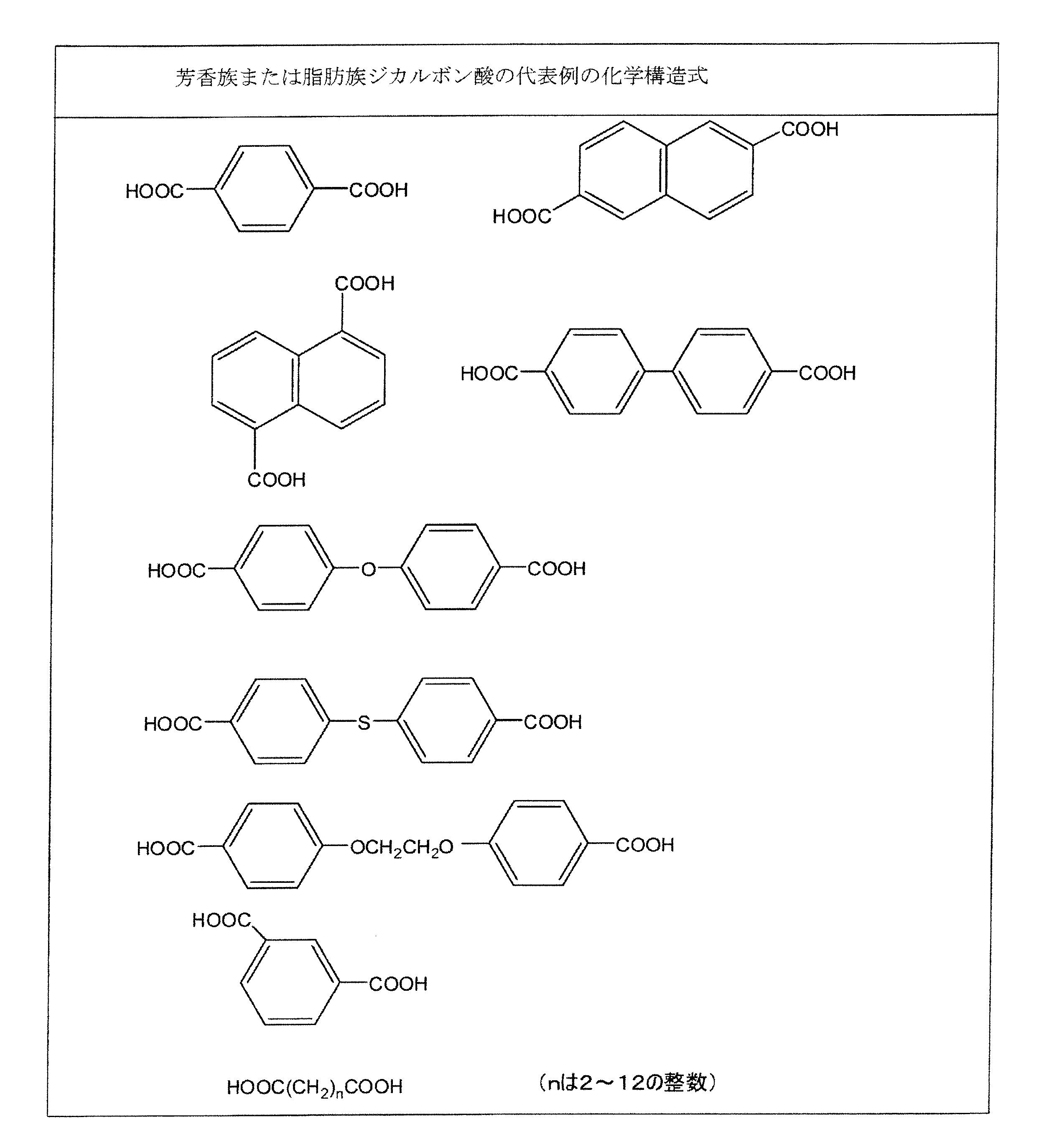
(2)芳香族または脂肪族ジカルボン酸(代表例は表2参照)
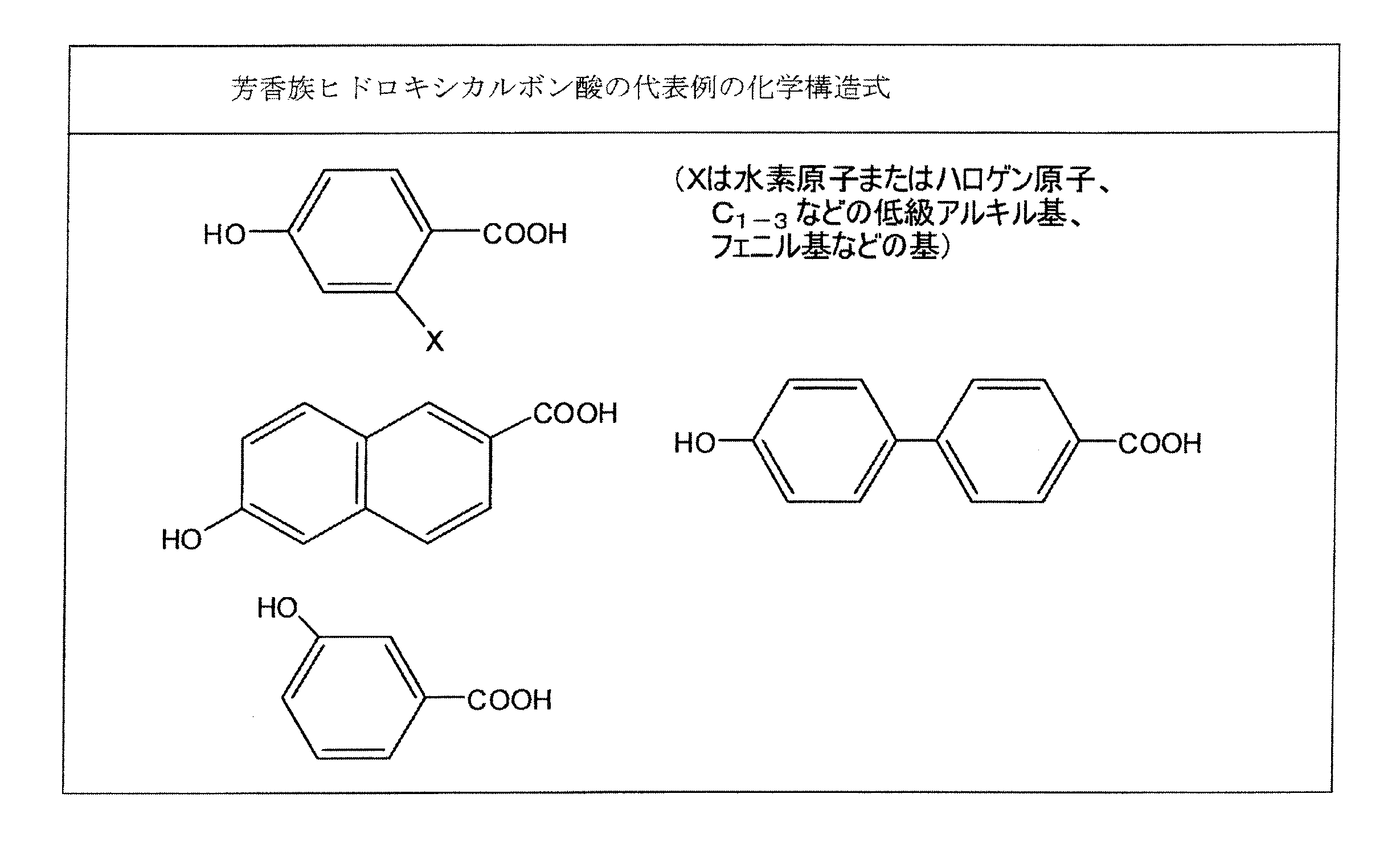
(3)芳香族ヒドロキシカルボン酸(代表例は表3参照)
(4)芳香族ジアミン、芳香族ヒドロキシアミンまたは芳香族アミノカルボン酸(代表例は表4参照)
これらの原料化合物から得られる液晶ポリマーの代表例として表5および6に示す構造単位を有する共重合体を挙げることができる。
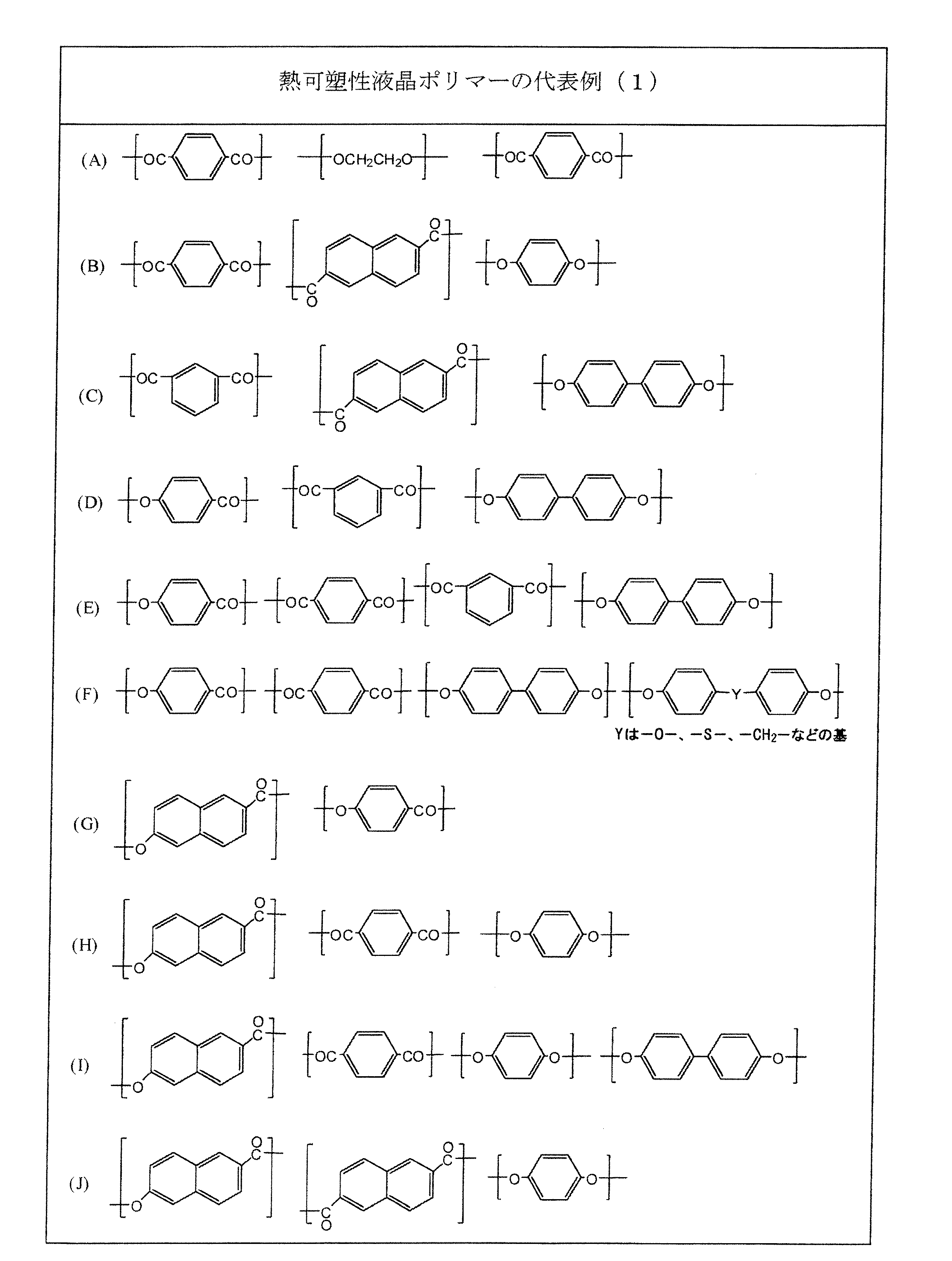

これらの共重合体のうち、p-ヒドロキシ安息香酸および/または6-ヒドロキシ-2-ナフトエ酸を少なくとも繰り返し単位として含む重合体が好ましく、特に、(i)p-ヒドロキシ安息香酸と6-ヒドロキシ-2-ナフトエ酸との繰り返し単位を含む重合体、又は(ii)p-ヒドロキシ安息香酸および6-ヒドロキシ-2-ナフトエ酸からなる群
から選ばれる少なくとも一種の芳香族ヒドロキシカルボン酸と、少なくとも一種の芳香族ジオールと、少なくとも一種の芳香族ジカルボン酸との繰り返し単位を含む共重合体が好ましい。
から選ばれる少なくとも一種の芳香族ヒドロキシカルボン酸と、少なくとも一種の芳香族ジオールと、少なくとも一種の芳香族ジカルボン酸との繰り返し単位を含む共重合体が好ましい。
例えば、(i)の重合体では、熱可塑性液晶ポリマーが、少なくともp-ヒドロキシ安息香酸と6-ヒドロキシ-2-ナフトエ酸との繰り返し単位を含む場合、繰り返し単位(A)のp-ヒドロキシ安息香酸と、繰り返し単位(B)の6-ヒドロキシ-2-ナフトエ酸とのモル比(A)/(B)は、液晶ポリマー中、(A)/(B)=10/90~90/10程度であるのが望ましく、より好ましくは、(A)/(B)=15/85~85/15程度であってもよく、さらに好ましくは、(A)/(B)=20/80~80/20程度であってもよい。
また、(ii)の重合体の場合、p-ヒドロキシ安息香酸および6-ヒドロキシ-2-ナフトエ酸からなる群から選ばれる少なくとも一種の芳香族ヒドロキシカルボン酸(C)と、4,4’-ジヒドロキシビフェニル、ヒドロキノン、フェニルヒドロキノン、および4,4’-ジヒドロキシジフェニルエーテルからなる群から選ばれる少なくとも一種の芳香族ジオール(D)と、テレフタル酸、イソフタル酸および2,6-ナフタレンジカルボン酸からなる群から選ばれる少なくとも一種の芳香族ジカルボン酸(E)の、液晶ポリマーにおける各繰り返し単位のモル比は、芳香族ヒドロキシカルボン酸(C):前記芳香族ジオール(D):前記芳香族ジカルボン酸(E)=(30~80):(35~10):(35~10)程度であってもよく、より好ましくは、(C):(D):(E)=(35~75):(32.5~12.5):(32.5~12.5)程度であってもよく、さらに好ましくは、(C):(D):(E)=(40~70):(30~15):(30~15)程度であってもよい。
また、芳香族ヒドロキシカルボン酸(C)のうち6-ヒドロキシ-2-ナフトエ酸に由来する繰り返し単位のモル比率は、例えば、85モル%以上であってもよく、好ましくは90モル%以上、より好ましくは95モル%以上であってもよい。芳香族ジカルボン酸(E)のうち2,6-ナフタレンジカルボン酸に由来する繰り返し単位のモル比率は、例えば、85モル%以上であってもよく、好ましくは90モル%以上、より好ましくは95モル%以上であってもよい。
また、芳香族ジオール(D)は、ヒドロキノン、4,4’-ジヒドロキシビフェニル、フェニルヒドロキノン、および4,4’-ジヒドロキシジフェニルエーテルからなる群から選ばれる互いに異なる二種の芳香族ジオールに由来する繰り返し単位(D1)と(D2)であってもよく、その場合、二種の芳香族ジオールのモル比は、(D1)/(D2)=23/77~77/23であってもよく、より好ましくは25/75~75/25、さらに好ましくは30/70~70/30であってもよい。
また、芳香族ジオールに由来する繰り返し構造単位と芳香族ジカルボン酸に由来する繰り返し構造単位とのモル比は、(D)/(E)=95/100~100/95であることが好ましい。この範囲をはずれると、重合度が上がらず機械強度が低下する傾向がある。
なお、本発明にいう光学的に異方性の溶融相を形成し得るとは、例えば試料をホットステージにのせ、窒素雰囲気下で昇温加熱し、試料の透過光を観察することにより認定できる。
熱可塑性液晶ポリマーとしては、融点(以下、Tmと称す)が200~360℃の範囲のものであってもよく、好ましくは240~360℃の範囲、より好ましくは260~360℃の範囲のものであり、さらに好ましくはTmが270~350℃のものである。なお、Tmは示差走査熱量計((株)島津製作所DSC)により主吸熱ピークが現れる温度を測定することにより求められる。
前記熱可塑性液晶ポリマーには、本発明の効果を損なわない範囲内で、ポリエチレンテレフタレート、変性ポリエチレンテレフタレート、ポリオレフィン、ポリカーボネート、ポリアリレート、ポリアミド、ポリフェニレンサルファイド、ポリエーテルエーテルケトン、フッ素樹脂等の熱可塑性ポリマー、各種添加剤、充填剤などを添加してもよい。
熱可塑性液晶ポリマーフィルムは、例えば、前記熱可塑性液晶ポリマーの溶融混練物を押出成形して得られる。押出成形法としては任意の方法のものが使用されるが、周知のTダイ法、インフレーション法等が工業的に有利である。特にインフレーション法では、熱可塑性液晶ポリマーフィルムの機械軸方向(以下、MD方向と略す)だけでなく、これと直交する方向(以下、TD方向と略す)にも応力が加えられ、MD方向、TD方向に均一に延伸できることから、MD方向とTD方向における分子配向性、誘電特性などを制御した熱可塑性液晶ポリマーフィルムが得られる。
例えば、Tダイ法による押出成形では、Tダイから押出した溶融体シートを、熱可塑性液晶ポリマーフィルムのMD方向だけでなく、これとTD方向の双方に対して同時に延伸して製膜してもよいし、またはTダイから押出した溶融体シートを一旦MD方向に延伸し、ついでTD方向に延伸して製膜してもよい。
また、インフレーション法による押出成形では、リングダイから溶融押出された円筒状シートに対して、所定のドロー比(MD方向の延伸倍率に相当する)およびブロー比(TD方向の延伸倍率に相当する)で延伸して製膜してもよい。
このような押出成形の延伸倍率は、MD方向の延伸倍率(またはドロー比)として、例えば、1.0~10程度であってもよく、好ましくは1.2~7程度、さらに好ましくは1.3~7程度であってもよい。また、TD方向の延伸倍率(またはブロー比)として、例えば、1.5~20程度であってもよく、好ましくは2~15程度、さらに好ましくは2.5~14程度であってもよい。
必要に応じて、公知または慣用の熱処理を行い、熱可塑性液晶ポリマーフィルムの面方向の熱膨張係数を所望の範囲に調整してもよい。熱可塑性液晶ポリマーフィルムの面方向の熱膨張係数は、例えば、特開2005-103989号公報に記載された方法により、所望の値に調整することができる。
熱可塑性液晶ポリマーフィルムの熱膨張係数は、例えば、-10ppm/℃~50ppm/℃の範囲のいずれかの値に調整されていてもよい。複数の熱可塑性液晶ポリマー副構造において、各副構造を構成する熱可塑性液晶ポリマーフィルムの熱膨張係数は、用途に応じて、例えば、最も高い値の熱膨張係数と、最も低い値の熱膨張係数の公差が、50ppm/℃以下、40ppm/℃以下、30ppm/℃以下、20ppm/℃以下、15ppm/℃以下、10ppm/℃以下、5ppm/℃以下、3ppm/℃以下、または1ppm/℃以下であってもよい。
その一方で、熱可塑性液晶ポリマー構造体に対してバイメタル的な性質を付与するために、各副構造を構成する熱可塑性液晶ポリマーフィルムの熱膨張係数が離れるように各副構造を組み合わせてもよく、その場合、例えば、隣接する熱可塑性液晶ポリマーフィルムの熱膨張係数が15ppm/℃以上、好ましくは18ppm/℃以上、さらに好ましくは20ppm/℃以上離れていてもよい。
(導体層と熱可塑性液晶ポリマーフィルムとの一体化工程)
熱可塑性液晶ポリマーフィルムに対して、導体層(信号層、電源層、グラウンド層などの導電性がある層、例えば、導体パターン、導体箔、導体膜などで形成された層)を形成する場合は、公知又は慣用の方法により導体層と熱可塑性液晶ポリマーフィルムとの一体化工程を行うことができる。この一体化工程により、導体層を一方の面に有する熱可塑性液晶ポリマーフィルムを作製してもよく、導体層を双方の面に有する熱可塑性液晶ポリマーフィルムを作製してもよい。
例えば、熱可塑性液晶ポリマーフィルムに対して金属箔などを熱圧着することにより、片面金属張積層体または両面金属張積層体とし、必要に応じてさらにエッチングすることなどにより、必要な導体層の形状を形成してもよい。
熱可塑性液晶ポリマーフィルムに対して、導体層(信号層、電源層、グラウンド層などの導電性がある層、例えば、導体パターン、導体箔、導体膜などで形成された層)を形成する場合は、公知又は慣用の方法により導体層と熱可塑性液晶ポリマーフィルムとの一体化工程を行うことができる。この一体化工程により、導体層を一方の面に有する熱可塑性液晶ポリマーフィルムを作製してもよく、導体層を双方の面に有する熱可塑性液晶ポリマーフィルムを作製してもよい。
例えば、熱可塑性液晶ポリマーフィルムに対して金属箔などを熱圧着することにより、片面金属張積層体または両面金属張積層体とし、必要に応じてさらにエッチングすることなどにより、必要な導体層の形状を形成してもよい。
導体層を形成する導体としては、導電性を有する各種金属、例えば、金、銀、銅、鉄、ニッケル、アルミニウムまたはこれらの合金金属などであってもよい。導体層の厚みは、必要に応じて適宜設定することができ、例えば、5~50μm程度であってもよく、より好ましくは8~35μmの範囲であってもよい。
このようにして、例えば、熱可塑性液晶ポリマー多層構造体において用いられる熱可塑性液晶ポリマー副構造として、(i)熱可塑性液晶ポリマーフィルム、(ii)導体層を一方の面に有する熱可塑性液晶ポリマーフィルム、および(iii)導体層を双方の面に有する熱可塑性液晶ポリマーフィルムを作製することができる。
(脱気乾燥工程)
必要に応じて、後述する昇温工程に先立って、熱可塑性液晶ポリマー副構造は、熱可塑性液晶ポリマーフィルムに存在するエアーや水分を除去するための脱気乾燥工程へ供せられてもよい。脱気乾燥工程は、熱可塑性液晶ポリマー副構造が重ね合わされた予備積層体を形成するのに先立って、個々の熱可塑性液晶ポリマー副構造およびこれらの組み合わせに対して行われてもよいし、予備積層体に対して行われてもよいし、双方が行われてもよい。脱気乾燥工程を行うことにより、熱可塑性液晶ポリマー構造体の一体性をより強固なものとすることができる。また、昇温工程や熱圧着工程にかかる時間を短くすることが可能となる。
必要に応じて、後述する昇温工程に先立って、熱可塑性液晶ポリマー副構造は、熱可塑性液晶ポリマーフィルムに存在するエアーや水分を除去するための脱気乾燥工程へ供せられてもよい。脱気乾燥工程は、熱可塑性液晶ポリマー副構造が重ね合わされた予備積層体を形成するのに先立って、個々の熱可塑性液晶ポリマー副構造およびこれらの組み合わせに対して行われてもよいし、予備積層体に対して行われてもよいし、双方が行われてもよい。脱気乾燥工程を行うことにより、熱可塑性液晶ポリマー構造体の一体性をより強固なものとすることができる。また、昇温工程や熱圧着工程にかかる時間を短くすることが可能となる。
予備積層体を形成するのに先立って行われる場合、脱気乾燥工程は、熱可塑性液晶ポリマーフィルムと導体層との一体化工程に先立って、熱可塑性液晶ポリマーフィルムにおいて行われてもよいし、熱可塑性液晶ポリマーフィルムと導体層との一体化工程の一部として行われてもよい。
脱気乾燥工程により、熱可塑性液晶ポリマー副構造の熱接着性を向上することができ、熱可塑性液晶ポリマー副構造の層間接着性を向上することができる。
脱気乾燥工程により、熱可塑性液晶ポリマー副構造の熱接着性を向上することができ、熱可塑性液晶ポリマー副構造の層間接着性を向上することができる。
脱気乾燥工程に供せられる熱可塑性液晶ポリマー副構造は、熱可塑性液晶ポリマーフィルムの脱気乾燥が可能である限り、その形状は特に限定されない。例えば、脱気乾燥工程において、熱可塑性液晶ポリマー副構造は、熱可塑性液晶ポリマーフィルム自体であってもよいし、熱可塑性液晶ポリマーフィルムの一方または双方の面に導体層が形成された熱可塑性液晶ポリマー副構造のシート物として供せられてもよい。さらに、これらの熱可塑性液晶ポリマー副構造は、必要に応じて、ロール状物として供せられてもよい。
さらにまた、必要に応じて、熱可塑性液晶ポリマー副構造は、複数の熱可塑性液晶ポリマー副構造の多層積層物(例えば、熱可塑性液晶ポリマー副構造が複数層に重ねられた多層積層物、仮組した多層回路など)の状態で、脱気乾燥工程に供せられてもよい。
脱気乾燥工程では、熱可塑性液晶ポリマー副構造に対して、特定の真空下での脱気乾燥(例えば真空乾燥)および/または加熱下での脱気乾燥(例えば加熱乾燥)を行うことにより、熱可塑性液晶ポリマーフィルムの内部や表面に存在するエアーや水分を極めて高度に低減することが可能となる。そして、このような脱気乾燥工程を経た熱可塑性液晶ポリマー副構造では、その熱接着性を向上させることが可能となる。
例えば、脱気乾燥工程が行われた熱可塑性液晶ポリマーフィルムでは、スキン層を破壊するといった軟化処理を行わなくとも、高い接着性を達成することが可能となる。ただし、軟化処理を否定するものではない。熱可塑性液晶ポリマーフィルムには、必要に応じて、軟化処理などの表面処理が行われてもよい。
脱気乾燥工程では、熱可塑性液晶ポリマー副構造を、(a)真空度1500Pa以下で30分以上、真空下で脱気乾燥させることにより、および/または(b)80℃~300℃の範囲で、加熱下で脱気乾燥させることより、熱可塑性液晶ポリマーフィルムを脱気乾燥することができる。脱気乾燥工程では、上記(a)真空下での脱気乾燥工程または(b)加熱下での脱気乾燥工程のいずれか一方を充足する条件で脱気乾燥すればよいが、上記(a)および(b)の双方を充足する条件で脱気乾燥することが好ましい。
(a)および(b)の双方を充足する条件で脱気乾燥する場合とは、(a)および(b)の双方が同時に充足される条件(すなわち、真空加熱下)で行われる脱気乾燥工程であってもよいし、熱可塑性液晶ポリマー副構造に対して(a)および(b)の条件が別々に行われる脱気乾燥工程、すなわち(a)から(b)の順、または(b)から(a)の順で別々に行われる脱気乾燥工程であってもよい。
なお、別々に脱気乾燥工程を行う場合、熱可塑性液晶ポリマーフィルムの熱接着性に悪影響を与えない範囲において、(a)および(b)の間、または(b)および(a)の間に別乾燥工程が行われてもよい。
また、脱気乾燥工程では、脱気乾燥性を向上させる観点から、実質的に加圧を行わない無加圧下(圧力解放下)で脱気乾燥を行ってもよい。例えば、低加圧または圧力解放状態(例えば、0~0.7MPa程度(ゲージ圧)の圧力下、好ましくは0~0.5MPa程度(ゲージ圧)の圧力下)で脱気乾燥工程を行ってもよい。
(a)真空下での脱気乾燥は、真空度1500Pa以下で行われてもよく、好ましくは1300Pa以下、より好ましくは1100Pa以下で行われてもよい。真空下での脱気乾燥を独立して行う場合、常温下(例えば10~50℃、好ましくは15~45℃の範囲)において行われてもよいが、脱気乾燥効率を高める観点から加熱下で行ってもよい。その場合の加熱温度は、例えば、50~300℃(例えば、50~250℃)、好ましくは80~250℃、より好ましくは80~200℃程度であってもよい。
(b)加熱下での脱気乾燥は、80~300℃の範囲で行われてもよく、好ましくは80~250℃の範囲、より好ましくは80~200℃の範囲で行ってもよい。また、加熱下での脱気乾燥は、熱可塑性液晶ポリマーまたは熱可塑性液晶ポリマーフィルムの融点Tmに対して、所定の温度範囲を設定してもよい。その場合は、例えば、(Tm-235)℃~(Tm-10)℃の範囲(例えば、(Tm-200)℃~(Tm-50)℃の範囲)で加熱してもよく、好ましくは、(Tm-225)℃~(Tm-50)℃の範囲(例えば、(Tm-190)℃~(Tm-60)℃の範囲)、より好ましくは、(Tm-215)℃~(Tm-70)℃の範囲(例えば、(Tm-180)℃~(Tm-70)℃の範囲)で行われてもよい。なお、熱可塑性液晶ポリマーフィルムの融点(Tm)は、例えば、270~380℃であってもよく、好ましくは280~370℃の範囲のものであってもよい。
上述のような、特定の温度範囲において加熱することにより、フィルムから急激に水分が発生することを抑制しつつ、フィルム中(例えば、フィルム内部やフィルム表面)の水分を水蒸気として脱気乾燥したり、表面に存在するエアーの運動エネルギーを高めてフィルム表面から脱気乾燥することが可能となる。
なお、加熱下での脱気乾燥を単独で行う場合、真空度1500Pa以下を含まない条件下で行われてもよく、例えば、圧力を調整しない大気圧下(または常圧下)で行ってもよいが、必要に応じて、大気圧から減圧された条件下(例えば、1500Paを超えて100000Pa未満、好ましくは3000~50000Pa程度)で加熱してもよい。
脱気乾燥工程に要する時間は、熱可塑性液晶ポリマー副構造中の熱可塑性液晶ポリマーフィルムの状態、真空度および/または加熱温度などの各種条件により適宜設定することができるが、熱可塑性液晶ポリマーフィルム全体から水分やエアーを除去する観点から、例えば、それぞれの脱気乾燥工程(真空下、加熱下、真空加熱下)について、同一または異なって、30分以上、40分以上、または50分以上であってもよく、6時間以下、4時間以下、3時間以下、2時間以下、または1.5時間以下であってもよい。
また、脱気乾燥工程に要する時間は、例えば、熱可塑性液晶ポリマーフィルムの水分率が、所定の範囲(例えば、380ppm以下、300ppm以下、または200ppm以下)になる時点を見計らって適宜設定してもよい。
また、脱気乾燥工程に要する時間は、例えば、熱可塑性液晶ポリマーフィルムの水分率が、所定の範囲(例えば、380ppm以下、300ppm以下、または200ppm以下)になる時点を見計らって適宜設定してもよい。
上述したように、脱気乾燥工程において、(a)真空下での脱気乾燥と(b)加熱下での脱気乾燥とを組み合わせて行う場合、熱可塑性液晶ポリマー副構造の熱接着性を向上できる範囲で、(a)真空下での脱気乾燥と(b)加熱下での脱気乾燥の順序はいずれを先にしてもよいが、好ましくは、第一の脱気乾燥工程として加熱下での脱気乾燥を行った後、第二の脱気乾燥工程として真空下での脱気乾燥を行ってもよい。
具体的には、例えば、脱気乾燥工程が、80℃~300℃の範囲で所定の時間加熱して、脱気乾燥を行う第一の脱気乾燥工程と、真空度1500Pa以下で、さらに所定の時間脱気乾燥を行う第二の脱気乾燥工程とを備えていてもよい。これらの脱気乾燥工程を行う際には、上述した条件を適宜組み合わせて行うことができる。
具体的には、例えば、脱気乾燥工程が、80℃~300℃の範囲で所定の時間加熱して、脱気乾燥を行う第一の脱気乾燥工程と、真空度1500Pa以下で、さらに所定の時間脱気乾燥を行う第二の脱気乾燥工程とを備えていてもよい。これらの脱気乾燥工程を行う際には、上述した条件を適宜組み合わせて行うことができる。
(熱可塑性液晶ポリマー構造体の製造方法)
本発明では、熱可塑性液晶ポリマー副構造を複数積層した予備積層体に対し、オートクレーブを用いてこれらを熱圧着することにより一体化された熱可塑性液晶ポリマー構造体を製造することができる。
前記製造方法は、複数の熱可塑性液晶ポリマー副構造が重ね合わせられた予備積層体をバギングフィルムで被覆し、前記バギングフィルムの端部をシールする封入工程と、前記バギングフィルム内部の排気を行い、予備加熱温度である第1温度まで昇温を行う昇温工程と、前記第1温度を起点として、オートクレーブの内圧を2.8MPa以下(ゲージ圧)の所望の圧力へ昇圧するとともに、熱圧着温度である第2温度へ昇温する熱圧着工程と、を少なくとも備えている。
本発明では、熱可塑性液晶ポリマー副構造を複数積層した予備積層体に対し、オートクレーブを用いてこれらを熱圧着することにより一体化された熱可塑性液晶ポリマー構造体を製造することができる。
前記製造方法は、複数の熱可塑性液晶ポリマー副構造が重ね合わせられた予備積層体をバギングフィルムで被覆し、前記バギングフィルムの端部をシールする封入工程と、前記バギングフィルム内部の排気を行い、予備加熱温度である第1温度まで昇温を行う昇温工程と、前記第1温度を起点として、オートクレーブの内圧を2.8MPa以下(ゲージ圧)の所望の圧力へ昇圧するとともに、熱圧着温度である第2温度へ昇温する熱圧着工程と、を少なくとも備えている。
(予備積層体のバギングフィルムへの封入工程)
封入工程では、複数の熱可塑性液晶ポリマー副構造が重ね合わせられた予備積層体を準備し、前記予備積層体をバギングフィルムで被覆した後(好ましくは包まれた後)、前記バギングフィルムの端部をシールする。前記予備積層体の積層構造は、用途などに応じて適宜決定される。
封入工程では、複数の熱可塑性液晶ポリマー副構造が重ね合わせられた予備積層体を準備し、前記予備積層体をバギングフィルムで被覆した後(好ましくは包まれた後)、前記バギングフィルムの端部をシールする。前記予備積層体の積層構造は、用途などに応じて適宜決定される。
バギングフィルムは、予備積層体を被覆可能であるとともに、オートクレーブ加熱条件に耐えることが可能であれば特に限定されず、単層であっても複数の材料が層状に組み合わされた複層であってもよい。
バギングフィルムは、例えば、耐熱性高分子フィルム(例えば、ポリイミドフィルム、フッ素系フィルム)であってもよいし、金属と耐熱性高分子フィルムとの複合材であってもよい。
予備積層体をバギングフィルムで直接被覆してもよく、排気を良好にする観点から、予備積層体とバギングフィルムとの間に、適宜、離型材、金属板、通気性シートなどを介在させてもよい。この場合、予備積層体に加えて、その他の構成部材(例えば、離型材、金属板、通気性シートなど)がバギングフィルムにより被覆され、または包まれてもよい。
離型材としては、熱可塑性液晶ポリマーに対して離型性を有する材料であれば特に限定されないが、例えば、ポリイミドフィルムやフッ素系フィルム(例えばポリテトラフルオロエチレンフィルム)、離型性多層複合材(例えば、第1の金属箔、互いにMD方向が直交する1対の高密度ポリエチレンシート、第2の金属箔、および低摩擦性フィルム)などを用いることができる。ここで、第1および第2の金属箔は、好ましくはアルミ箔であってもよく、低摩擦性フィルムは、JIS K 7125で定義される静摩擦係数が0.30以下(好ましくは、0.05~0.25程度)の低い摩擦係数を有するフィルム、具体的には、超高分子量ポリエチレンフィルム、ポリテトラフルオロエチレンフィルムなどであってもよい。
通気性シートとしては、耐熱性を有する多孔質材料で形成されていれば特に限定されないが、例えば、ガラスクロス、耐熱性繊維布帛、または金属メッシュのシート状物などを用いることができる。
また、通気性シートを用いる場合、通気性シートに由来して予備積層体の表面に模様が転写されることを防ぐため、予備積層体と通気性シートの間に、適宜金属板を介在させてもよい。金属板を構成する金属としては、例えば、耐圧縮性の高い公知または慣用の金属材料を用いることができ、好ましくはステンレス鋼である。
金属板は、例えば、厚みが、0.1mm~1cm程度であってもよく、好ましくは0.2mm~0.8mm程度、さらに好ましくは0.3mm~0.6mm程度であってもよい。
予備積層体をバギングフィルムで被覆した後、バギングフィルム内部の排気を行うために前記バギングフィルムの端部をシールする。端部をシールするに当たって、バギングフィルムの対向する端部をシールできる限り、特に限定されず、テープ類などのシール手段でシールしてもよいし、万力などの治具で押さえてシールしてもよいし、これらを組み合わせてシールしてもよい。
(昇温工程)
昇温工程では、前記バギングフィルム内部の排気を行い、予備加熱温度である第1温度まで昇温が行われる。バギングフィルム内部の排気機構は、排気ができる限り特に限定されないが、例えば、バギングフィルムの端部をシールした後、バギングフィルム内部の排気を行う。昇温は、バギングフィルムの排気の前に行われても、排気と重なっていても、排気の後に行われても、いずれであってもよい。
昇温工程では、前記バギングフィルム内部の排気を行い、予備加熱温度である第1温度まで昇温が行われる。バギングフィルム内部の排気機構は、排気ができる限り特に限定されないが、例えば、バギングフィルムの端部をシールした後、バギングフィルム内部の排気を行う。昇温は、バギングフィルムの排気の前に行われても、排気と重なっていても、排気の後に行われても、いずれであってもよい。
昇温工程では、所定の時間第1温度で保持することにより予備加熱が行われてもよい。予備加熱までの間、オートクレーブ内部で加圧ガスの供給による積極的な加圧が行われないことが好ましい。
第1温度は予備加熱温度である。好ましくは、第1温度では、熱可塑性液晶ポリマー分子は激しい流動性を有していない。
第1温度は、例えば、予備積層体を形成する中で予備加熱対象の熱可塑性液晶ポリマー要素の融点をMLとした場合、第1温度は、例えば、(ML-150)℃~(ML-50)℃の範囲であってもよく、好ましくは(ML-130)℃~(ML-70)℃程度であってもよい。熱可塑性液晶ポリマー分子が急激に流動するのを防止する観点からは、予備加熱対象の熱可塑性液晶ポリマー要素は、予備積層体の中で最も融点の低い熱可塑性液晶ポリマー要素であってもよい。第1温度は、熱可塑性液晶ポリマーの流動開始温度に応じて、適宜設定することが可能であるが、例えば、150~250℃の範囲であってもよく、好ましくは180~230℃程度であってもよい。
昇温工程における昇温速度は、例えば、1~10℃/minで行われてもよく、好ましくは2~8℃/minで行われてもよい。
第1温度での保持時間(または予備加熱時間)は、予備積層体の層間における熱圧着が行われる限り特に限定されず、脱気処理の有無や予備加熱温度に応じて適宜異なるが、第1温度での保持時間(または予備加熱時間)は、例えば、1~120分間程度行われてもよく、好ましくは3~60分間程度行われてもよい。また、第1温度での所定の保持時間(または予備加熱時間)を経過した場合、例えば、予備加熱対象の熱可塑性液晶ポリマー要素の水分率が、所定の範囲(例えば、380ppm以下、300ppm以下、または200ppm以下)であってもよい。
脱気乾燥工程が行われる場合は、第1温度での保持時間は、1~20分間程度行われてもよく、好ましくは2~15分間程度行われてもよく、より好ましくは2~10分程度行われてもよい。
(熱圧着工程)
熱圧着工程では、前記第1温度を起点として、オートクレーブの内圧を2.8MPa以下(ゲージ圧)の所望の圧力へ昇圧するとともに、熱圧着温度である第2温度へ昇温して、予備積層体の層間における熱圧着が行われる。
熱圧着工程では、前記第1温度を起点として、オートクレーブの内圧を2.8MPa以下(ゲージ圧)の所望の圧力へ昇圧するとともに、熱圧着温度である第2温度へ昇温して、予備積層体の層間における熱圧着が行われる。
昇圧と並行して、所望の第2温度へ第2の昇温工程を行う。昇温速度は、2~20℃/minであってもよく、好ましくは3~15℃/min、より好ましくは4~10℃/minであってもよい。第2温度は最高加熱温度であってもよく、第2温度により予備積層体中の熱可塑性液晶ポリマー副構造が熱圧着される。その後、熱可塑性液晶ポリマー副構造の積層体は冷却され、圧力を解放した後、熱可塑性液晶ポリマー構造体として得ることができる。
加圧下において熱可塑性液晶ポリマーが過度に流動するのを防ぐため、オートクレーブにおける最大圧力は、2.8MPa以下(ゲージ圧)であることが必要であり、好ましくは2.5MPa以下(ゲージ圧)、さらに好ましくは2MPa以下(ゲージ圧)であってもよい。熱可塑性液晶ポリマー副構造を接着することができる限り、最大圧力の下限値は特に限定されないが、例えば、1.5MPa(ゲージ圧)であってもよい。
第2温度は、熱圧着温度である。熱圧着温度は、熱可塑性液晶ポリマー副構造の熱可塑性液晶ポリマー要素間で、隣接する副構造のいずれか一方が融着できる範囲であれば限定されない。例えば、熱圧着温度は、事前に熱可塑性液晶ポリマー副構造の熱融着温度を把握した上で決定してもよい。例えば、予備積層体を形成する中で融着対象の熱可塑性液晶ポリマー要素の融点をMHとした場合、第2温度は、例えば、(MH-30)℃~(MH+10)℃の範囲であってもよく、好ましくは(MH-10)℃~(MH+5)℃程度であってもよい。確実な融着を行う観点からは、融着対象の熱可塑性液晶ポリマー要素は、予備積層体の中で最も融点の高い熱可塑性液晶ポリマー要素であってもよい。
第2温度での保持時間(または熱圧着時間)は、予備積層体の層間における熱圧着が行われる限り特に限定されず、脱気乾燥処理の有無や熱圧着温度に応じて適宜変更すること
が可能であるが、例えば、15~60分間程度行われてもよく、好ましくは20~50分間程度、さらに好ましくは20~40分間程度行われてもよい。
が可能であるが、例えば、15~60分間程度行われてもよく、好ましくは20~50分間程度、さらに好ましくは20~40分間程度行われてもよい。
このような製造方法により、急激な熱可塑性液晶ポリマー分子の流動を抑制しつつも、隣接する熱可塑性液晶ポリマー副構造間で良好な接着性を達成することができる。
以下に、オートクレーブを用いた熱可塑性液晶ポリマー構造体の製造方法を、一実施態様を例示しつつ、さらに説明する。
図1に、本発明の一実施態様による、オートクレーブ式熱圧着法を説明するための概略図を示す。オートクレーブ9内部では、バギングフィルム1によって包まれ、所望の構成により複数の熱可塑性液晶ポリマー副構造を重ね合わせた予備積層体5が、キャリアプレート6の上に戴置される。ここで、バギングフィルム1の内部では、予備積層体5の上下面に離型材4a,4bが配設され、さらに上面の離型材4aの上には、トッププレート3を介在させて通気性シート2が配設される。
バギングフィルム1はバキュームシーラントテープ8により封止され、バギングフィルム1の適当な箇所において、真空引きのためのバキュームノズル7が接続されている。バギングフィルム1内部の空気は、バキュームノズル7により排気される。なお、バギングフィルム1の内側には、必要に応じて通気性シート2が配設されてもよい。通気性シート2が存在することにより、バギングフィルム1の内部の排気性をより高めることができる。
なお、図1において、通気性シート2は、予備積層体5の上方から予備積層体5の側方をへて、バキュームノズル7へ通じるように配設されている。しかし、通気性シート2の設定場所は、予備積層体5の周囲において、排気性を高めることができる限り限定されない。例えば、通気性シート2は、予備積層体5の上方、下方、側方から選択される、少なくとも一か所において配設されてもよい。また、通気性シート2を予備積層体5の上方および/または下方に設ける場合、離型材4a,4bと通気性シート2との間に、金属板を介在して設けるのが好ましい。
また、図1において、バギングフィルム1は予備積層体5の上方および下方の双方に配設され、端部においてバキュームシーラントテープ8により封止されて、予備積層体5を梱包する状態で被覆している。
なお、バギングフィルム1内部の排気が可能であれば、下方のバギングフィルム1は配設しなくてもよい。予備積層体5をバギングフィルム1で上方から被覆し、前記バギングフィルム1の端部を、キャリアプレート6に対して、所定のシール手段(例えばバキュームシーラントテープなどのテープ類)を用いてシールしてもよい。前記シール手段による密着が少ない場合は、さらに、シール手段とポリイミドフィルムを万力などの治具で押さえつけても良い。
熱圧着を行う際には、ガス源(図示せず)からオートクレーブ9内部へ、加圧ガスを供給する。供給された加圧ガスは、バギングフィルム1の周囲に均一に存在するため、バギングフィルム1の内部を均等に加圧することが可能となる。
一方、バギングフィルム1の内部は排気されているため、バギングフィルム1に対してかかる圧力は、そのまま積層体5に対してかかることになる。その結果、予備積層体5は、上面および下面だけでなく、その側面からも等しい圧力が加圧され、予備積層体5内部の各熱可塑性液晶ポリマー副構造を互いに接着させることができる。
オートクレーブ9において用いられる各種部材は、公知又は慣用の部材を用いることができる。また、上述した部材に代えて、または加えて別の部材を用いてもよい。
例えば、バギングフィルム1は、耐熱性および耐圧性を有する可撓性材料であれば特に限定されないが、例えば、ポリイミドフィルムなどが挙げられる。離型材4a,4bとしては、例えば、ポリイミドフィルム、フッ素系フィルム、離型性多層複合材などが用いられる。
また、通気性シート2としては、バギングフィルム1と予備積層体5との間に存在する空気を排気するために用いることができる限り特に限定されないが、例えば、ガラスクロス、耐熱性繊維布帛、または金属メッシュのシート状物などを用いることができる。
また、金属板は、通気性シート2に由来する形状が、熱可塑性液晶ポリマー構造体の表面に写るのを防ぐために配設される。したがって、通気性シート2が配設されない場合は、金属板についても配設しなくてもよい。
加圧ガスとしては、加熱下で高反応性を有するガスでなければ特に限定されず、通常の大気などであってもよいが、窒素ガスなどを適宜使用してもよい。
本発明では、オートクレーブ式熱圧着法において、特定の加熱条件を行うことにより、熱可塑性液晶ポリマー分子の過度の流動を抑制しつつ、熱可塑性液晶ポリマー副構造同士を接着させることができる。そして、熱可塑性液晶ポリマー分子の流動を緩やかにすることができるため、熱可塑性液晶ポリマー構造体の配向を均質にするとともに、熱可塑性液晶ポリマー構造体の一体性を高めることができる。また、導体パターンで形成された回路が存在する場合には、回路近傍における熱可塑性液晶ポリマーの流動を緩やかにし、回路が存在していても、熱可塑性液晶ポリマーの配向性を均一にすることができる。
第1温度を起点とし、オートクレーブ内部に加熱・加圧ガスを供給し、オートクレーブの内圧を所望の最大圧力へ昇圧する。この場合、2.8MPa以下(ゲージ圧)の所望の圧力下で予備積層体が加圧されて、熱圧着が行われる。
(熱可塑性液晶ポリマー構造体)
得られた熱可塑性液晶ポリマー構造体は、熱可塑性液晶ポリマー副構造の一体性に優れつつ、製造過程において構造体を構成する熱可塑性液晶ポリマー分子が過度に流動することに由来する樹脂フローの発生を抑制し得る。
得られた熱可塑性液晶ポリマー構造体は、熱可塑性液晶ポリマー副構造の一体性に優れつつ、製造過程において構造体を構成する熱可塑性液晶ポリマー分子が過度に流動することに由来する樹脂フローの発生を抑制し得る。
本発明の熱可塑性液晶ポリマー構造体は、オートクレーブを用いて複数の熱可塑性液晶ポリマー副構造を一体化することにより、積層後の各副構造の熱可塑性液晶ポリマー要素の熱膨張係数が所定の値に制御されてもよいし、熱可塑性液晶ポリマー構造体を形成する前に、予め熱可塑性液晶ポリマーフィルムの熱膨張係数が調整されてもよい。
なお、積層の際の熱圧着時において熱可塑性液晶ポリマー要素の熱膨張係数が調整されない場合、熱可塑性液晶ポリマー要素(または熱可塑性液晶ポリマー層)の熱膨張係数は、熱可塑性液晶ポリマー構造体を構成する各熱可塑性液晶ポリマー副構造で用いられた熱可塑性液晶ポリマーフィルムの熱膨張係数と同じと判断してもよい。
なお、積層の際の熱圧着時において熱可塑性液晶ポリマー要素の熱膨張係数が調整されない場合、熱可塑性液晶ポリマー要素(または熱可塑性液晶ポリマー層)の熱膨張係数は、熱可塑性液晶ポリマー構造体を構成する各熱可塑性液晶ポリマー副構造で用いられた熱可塑性液晶ポリマーフィルムの熱膨張係数と同じと判断してもよい。
熱可塑性液晶ポリマー構造体における熱可塑性液晶ポリマー要素の面方向の熱膨張係数は、例えば、-10ppm/℃~50ppm/℃の範囲であってもよく、好ましくは10ppm/℃~50ppm/℃の範囲、より好ましくは15ppm/℃~45ppm/℃の範囲であってもよい。なお、熱可塑性液晶ポリマー構造体における熱可塑性液晶ポリマー要素の面方向の熱膨張係数は、熱可塑性液晶ポリマー構造体の表面または裏面のそれぞれについて、所定の厚み(例えば、10~100μmの範囲、最外層の熱可塑性液晶ポリマー層の積層状態が明確である場合はその厚み)の熱可塑性液晶ポリマー要素を採取した値により評価してもよい。
また、熱可塑性液晶ポリマー構造体における熱可塑性液晶ポリマー要素の面方向の熱膨張係数の公差は、用途に応じて、例えば、50ppm/℃以下、40ppm/℃以下、30ppm/℃以下、20ppm/℃以下であってもよく、15ppm/℃以下、10ppm/℃以下、5ppm/℃以下、3ppm/℃以下、または1ppm/℃以下であってもよい。なお、熱可塑性液晶ポリマー構造体における熱可塑性液晶ポリマー要素の面方向の熱膨張係数の公差は、熱可塑性液晶ポリマー構造体からサンプル片として複数の熱可塑性液晶ポリマー要素をランダムに採取し、得られたサンプル片の面方向の熱膨張係数の最大値および最小値の差であってもよいが、簡便性の観点からは、熱可塑性液晶ポリマー構造体の表面および裏面のそれぞれについて、所定の厚み(例えば、10~100μmの範囲、最外層の熱可塑性液晶ポリマー層が明確である場合はその厚み)の熱可塑性液晶ポリマー要素を採取し、その面方向の熱膨張係数の差を公差としてもよい。
熱可塑性液晶ポリマー構造体において、前記熱可塑性液晶ポリマー副構造は、好ましくは、(i)熱可塑性液晶ポリマー層、(ii)導体層を一方の面に有する熱可塑性液晶ポリマー層、および(iii)導体層を双方の面に有する熱可塑性液晶ポリマー層からなる群から選択された少なくとも2層の熱可塑性液晶ポリマー副構造で構成されていてもよい。
熱可塑性液晶ポリマー副構造としては、熱可塑性液晶ポリマーから形成され、複数の副構造が一体化可能である限りさまざまな形状の副構造を用いることが可能である。好ましくは、熱可塑性液晶ポリマー副構造は、(i)熱可塑性液晶ポリマー層単独(L)、(ii)導体層を一方の面に有する熱可塑性液晶ポリマー層(CL)、および(iii)導体層を双方の面に有する熱可塑性液晶ポリマー層(CLC)からなる群から選択することができる。ここで、導体層としては、導電性がある層である、例えば、信号層、電源層、グラウンド層などが挙げられ、具体的には、導体パターン、導体箔、導体膜などで形成された層が挙げられ、これらの導体層には、必要に応じて、適宜所望の形状が形成されていてもよい。
熱可塑性液晶ポリマー副構造の好ましい組み合わせとしては、例えば、以下の組み合わせが挙げられる。
(I)複数のL
(II)複数のCL
(III)複数のCLC
(IV)一または複数のLおよび一または複数のCL
(V)一または複数のLおよび一または複数のCLC
(VI)一または複数のL、一または複数のCL、および一または複数のCLC、ならびに
(VII)一または複数のCLおよび一または複数のCLC。
ここで、L:熱可塑性液晶ポリマー層単独、CL:導体層を一方の面に有する熱可塑性液晶ポリマー層、およびCLC:導体層を双方の面に有する熱可塑性液晶ポリマー層を意味する。これらの中で、L,CL,およびLCLを重ね合わせる順序や向きは、用途に応じて適宜設定することが可能である。
(I)複数のL
(II)複数のCL
(III)複数のCLC
(IV)一または複数のLおよび一または複数のCL
(V)一または複数のLおよび一または複数のCLC
(VI)一または複数のL、一または複数のCL、および一または複数のCLC、ならびに
(VII)一または複数のCLおよび一または複数のCLC。
ここで、L:熱可塑性液晶ポリマー層単独、CL:導体層を一方の面に有する熱可塑性液晶ポリマー層、およびCLC:導体層を双方の面に有する熱可塑性液晶ポリマー層を意味する。これらの中で、L,CL,およびLCLを重ね合わせる順序や向きは、用途に応じて適宜設定することが可能である。
熱可塑性液晶ポリマー副構造を構成する熱可塑性液晶ポリマーフィルム(熱圧着後においては熱可塑性液晶ポリマー層)の厚みは、用途に応じて適宜設定することが可能であるが、好ましくは全て140μm以下であってもよく、より好ましくは120μm以下、さらに好ましくは110μm以下であってもよい。また、熱可塑性液晶ポリマーフィルム(または熱可塑性液晶ポリマー層)の厚みの下限値は、10μm程度であってもよいが、目的とする厚みに応じて、15μm以上、30μm以上、60μm以上、または85μm以上であってもよい。各副構造を構成する熱可塑性液晶ポリマーフィルム(または熱可塑性液晶ポリマー層)の厚みは、同一であっても異なっていてもよいが、同程度(例えば、各厚みの差が10%以下、好ましくは5%以下)である方が好ましい。
用途に応じて熱可塑性液晶ポリマー副構造の数は適宜設定することができ、熱可塑性液晶ポリマー副構造の数は、薄手用途として用いられる場合は、例えば、2~10程度、好ましくは3~8程度であってもよい。その場合、各熱可塑性液晶ポリマー副構造の厚みは、10~70μm程度、好ましくは10~60μm程度であってもよい。
薄手用途の場合、例えば、熱可塑性液晶ポリマー構造体の厚みは、30μm以上、50μm以上、100μm以上であってもよい。厚みの上限は適宜設定することが可能であるが、例えば、150μm以下であってもよい。
薄手用途の場合、例えば、熱可塑性液晶ポリマー構造体の厚みは、30μm以上、50μm以上、100μm以上であってもよい。厚みの上限は適宜設定することが可能であるが、例えば、150μm以下であってもよい。
また、熱可塑性液晶ポリマー副構造の数は、厚手用途として用いられる場合は、熱可塑性液晶ポリマー構造体に求められる厚みや、熱可塑性液晶ポリマー副構造の厚みに応じて、例えば、2以上、3以上、4以上、9以上、または10以上であってもよい。また、上限は特に限定されないが、例えば、200以下、150以下、100以下、50以下、20以下、または15以下であってもよい。なお、これらの上限および下限に関する記載は、自由に組み合わせることができる。その場合、各熱可塑性液晶ポリマー副構造の厚みは、50~140μm程度、好ましくは70~120μm程度であってもよい。
厚手用途の場合、例えば、熱可塑性液晶ポリマー構造体は、150μmを超えていてもよく、250μm以上、350μm以上、450μm以上、または550μm以上であってもよい。厚みの上限は適宜設定することが可能であるが、例えば、5mm以下であってもよい。
厚手用途の場合、例えば、熱可塑性液晶ポリマー構造体は、150μmを超えていてもよく、250μm以上、350μm以上、450μm以上、または550μm以上であってもよい。厚みの上限は適宜設定することが可能であるが、例えば、5mm以下であってもよい。
また、熱可塑性液晶ポリマー構造体を構成する各熱可塑性液晶ポリマー副構造の熱可塑性液晶ポリマー要素は、それぞれの融点が同一であっても、異なっていてもよい。異なっている場合は、最も融点の低い熱可塑性液晶ポリマー要素と、最も融点の高い熱可塑性液晶ポリマー要素との間の温度差が、0℃を越えて100℃以下、好ましくは10℃以上90℃以下、より好ましくは20℃以上80℃以下であってもよい。
前記熱可塑性液晶ポリマー構造体は、導体層(例えば、金属箔層または金属箔からなる導体パターン)を3層以上有していてもよい。また、用途に応じて、導体層を5層以上、7層以上有していてもよい。導体層の上限は特に限定されないが、20層程度であってもよい。
熱可塑性液晶ポリマー構造体が、前記熱可塑性液晶ポリマー層で構成された熱可塑性液晶ポリマー副構造の積層体である場合、本発明の熱可塑性液晶ポリマー構造体は一体性に優れているため、隣接する熱可塑性液晶ポリマー副構造間で熱圧着性を有する。ここで、熱圧着性(または接着性)を有するとは、後述する実施例に記載した方法により評価される接着強度が、例えば0.4N/mm以上であり、好ましくは0.5N/mm以上、より好ましくは0.6N/mm以上、さらに好ましくは0.7N/mm以上、よりさらに好ましくは0.8N/mm以上、特に好ましくは0.9N/mm以上、さらに特に好ましくは1.0N/mm以上であってもよい。接着強度の上限は特に限定されないが、2.0N/mm程度であってもよい。
特に、本発明では、厚手用途に用いられる場合でも、熱圧着により構造を一体化でき、隣接する副構造間の接着強度を高めることができて好ましい。
特に、本発明では、厚手用途に用いられる場合でも、熱圧着により構造を一体化でき、隣接する副構造間の接着強度を高めることができて好ましい。
また、本発明では、等方性に優れる熱可塑性液晶ポリマー構造体を得ることも可能であり、その場合、熱可塑性液晶ポリマー構造体の分子配向度SORは、例えば、0.95~1.25程度であってもよく、好ましくは0.98~1.18程度であってもよい。なお、熱可塑性液晶ポリマー構造体の分子配向度SORは、後述する実施例に記載された方法により測定される値である。
また、本発明では、隣接する熱可塑性液晶ポリマー副構造におけるそれぞれの熱可塑性液晶ポリマー要素の面方向の熱膨張係数の差が、例えば15ppm/℃以上であってもよく、好ましくは18ppm/℃以上、さらに好ましくは20ppm/℃以上であってもよい。この場合、所定の温度において低熱膨張率を有する熱可塑性液晶ポリマー副構造側に湾曲する、バイメタル的な性質を有する熱可塑性液晶ポリマー構造体を得ることも可能である。
本発明の熱可塑性液晶ポリマー構造体は、さまざまな熱可塑性液晶ポリマー副構造を組み合わせることによって、板状物などの3次元立体構造体、棒状物などの2次元立体構造体などを得ることができ、構造体は一体性が高く、構造体内部での分子の過度な流動が抑制されている。
例えば、本発明の熱可塑性液晶ポリマー構造体は、電気・電子分野や、事務機器・精密機器分野などにおいて用いられる部品として有効に用いることができ、例えば、多層回路基板(特にミリ波レーダ用基板)、パワーモジュールなどとして有用に用いることができる。
例えば、本発明の熱可塑性液晶ポリマー構造体は、電気・電子分野や、事務機器・精密機器分野などにおいて用いられる部品として有効に用いることができ、例えば、多層回路基板(特にミリ波レーダ用基板)、パワーモジュールなどとして有用に用いることができる。
以下、実施例により本発明をより詳細に説明するが、本発明は本実施例により何ら限定されるものではない。なお、以下の実施例及び比較例においては、下記の方法により各種物性を測定した。
[融点]
TAインスツルメント製 DSC Q2000を用いて、サンプル5mgについて、室温から毎分20℃の速度でサンプルを重合した温度まで昇温を行い、その温度で2分保持し、毎分20℃の速度で25℃まで冷却を行い、25℃で2分保持し、再び毎分20℃の速度で昇温した際の、吸熱ピーク温度を融点とした。
TAインスツルメント製 DSC Q2000を用いて、サンプル5mgについて、室温から毎分20℃の速度でサンプルを重合した温度まで昇温を行い、その温度で2分保持し、毎分20℃の速度で25℃まで冷却を行い、25℃で2分保持し、再び毎分20℃の速度で昇温した際の、吸熱ピーク温度を融点とした。
[熱膨張係数]
熱可塑性液晶ポリマーフィルムの熱膨張係数は熱機械分析装置((株)島津製作所製 TMA-60)を用いて、幅5mm、長さ20mmの熱可塑性液晶ポリマーフィルムの両端に1gの引張荷重をかけ、室温から5℃/分の速度で200℃まで昇温した後、20℃/分の速度で30℃まで冷却し、再び5℃/分の速度で昇温した時の30℃と150℃の間の長さの変化に基づいて算出した。
熱可塑性液晶ポリマー構造体における熱可塑性液晶ポリマー要素の面方向の熱膨張係数は代表値として、表面および裏面のそれぞれについて、最外層の熱可塑性液晶ポリマー層を剥離し、得られた二層をそれぞれ熱可塑性液晶ポリマーフィルムとみなした。そして、上述のように熱可塑性液晶ポリマーフィルムの熱膨張係数の測定と同様の方法で、それぞれの層の測定を行った。熱可塑性液晶ポリマー構造体における熱可塑性液晶ポリマー要素の面方向の熱膨張係数の公差については、得られた二層のそれぞれの熱膨張係数について、一方を最大値、もう一方を最小値として、その差を熱可塑性液晶ポリマー要素の熱膨張係数の公差とした。
熱可塑性液晶ポリマーフィルムの熱膨張係数は熱機械分析装置((株)島津製作所製 TMA-60)を用いて、幅5mm、長さ20mmの熱可塑性液晶ポリマーフィルムの両端に1gの引張荷重をかけ、室温から5℃/分の速度で200℃まで昇温した後、20℃/分の速度で30℃まで冷却し、再び5℃/分の速度で昇温した時の30℃と150℃の間の長さの変化に基づいて算出した。
熱可塑性液晶ポリマー構造体における熱可塑性液晶ポリマー要素の面方向の熱膨張係数は代表値として、表面および裏面のそれぞれについて、最外層の熱可塑性液晶ポリマー層を剥離し、得られた二層をそれぞれ熱可塑性液晶ポリマーフィルムとみなした。そして、上述のように熱可塑性液晶ポリマーフィルムの熱膨張係数の測定と同様の方法で、それぞれの層の測定を行った。熱可塑性液晶ポリマー構造体における熱可塑性液晶ポリマー要素の面方向の熱膨張係数の公差については、得られた二層のそれぞれの熱膨張係数について、一方を最大値、もう一方を最小値として、その差を熱可塑性液晶ポリマー要素の熱膨張係数の公差とした。
[接着強度]
JIS C5016-1994に準拠して、毎分50mmの速度で、隣接する熱可塑性液晶ポリマーフィルム間において、一方を、他方に対し90°の方向に引きはがしながら、引っ張り試験機((株)イマダ製 デジタルフォースゲージZTS-500N)により、引きはがし強さを測定し、得られた値を接着強度とした。熱圧着性の判断は、隣接する熱可塑性液晶ポリマー副構造同士が剥がれない実用上問題のない接着強度の下限値が0.4N/mmであることを確認した上で、隣接する熱可塑性液晶ポリマー副構造間の接着強度が0.4N/mm以上である場合を接着性良好とし、合格の範囲内であると判断した。
なお、熱可塑性液晶ポリマーフィルムの一方向(MD方向)と、それに対する直交方向(TD方向)について、それぞれ、両側から引きはがすことにより、MD順方向(またはMD進行方向)、MD逆方向(またはMD非進行方向)、TD順方向(またはTD右方向)、TD逆方向(またはTD左方向)の4方向について接着強度を測定し、その平均値を熱可塑性液晶ポリマーフィルム間の接着強度の代表値とした。
また、接着強度はランダムに選択した当接する二層を引きはがし、その強度により評価した。
JIS C5016-1994に準拠して、毎分50mmの速度で、隣接する熱可塑性液晶ポリマーフィルム間において、一方を、他方に対し90°の方向に引きはがしながら、引っ張り試験機((株)イマダ製 デジタルフォースゲージZTS-500N)により、引きはがし強さを測定し、得られた値を接着強度とした。熱圧着性の判断は、隣接する熱可塑性液晶ポリマー副構造同士が剥がれない実用上問題のない接着強度の下限値が0.4N/mmであることを確認した上で、隣接する熱可塑性液晶ポリマー副構造間の接着強度が0.4N/mm以上である場合を接着性良好とし、合格の範囲内であると判断した。
なお、熱可塑性液晶ポリマーフィルムの一方向(MD方向)と、それに対する直交方向(TD方向)について、それぞれ、両側から引きはがすことにより、MD順方向(またはMD進行方向)、MD逆方向(またはMD非進行方向)、TD順方向(またはTD右方向)、TD逆方向(またはTD左方向)の4方向について接着強度を測定し、その平均値を熱可塑性液晶ポリマーフィルム間の接着強度の代表値とした。
また、接着強度はランダムに選択した当接する二層を引きはがし、その強度により評価した。
[分子配向度(SOR)]
熱可塑性液晶ポリマー構造体から、マイクロ波共振導波管中に挿入できる程度に切片を切り出し、サンプルとした。なお、熱可塑性液晶ポリマー構造体がそのまま挿入可能な場合は、切片を切り出さずにサンプルとした。
マイクロ波分子配向度測定機において、サンプルを、マイクロ波の進行方向にサンプル面が垂直になるように、マイクロ波共振導波管中に挿入し、該サンプルを透過したマイクロ波の電場強度(マイクロ波透過強度)を測定する。そして、この測定値に基づいて、次式により、m値(屈折率と称する)を算出する。
m=(Zo/Δz)X[1-νmax/νo]
ここで、Zoは装置定数、Δzは物体の平均厚、νmaxはマイクロ波の振動数を変化させたとき、最大のマイクロ波透過強度を与える振動数、νoは平均厚ゼロのとき(すなわち物体がないとき)の最大マイクロ波透過強度を与える振動数である。
熱可塑性液晶ポリマー構造体から、マイクロ波共振導波管中に挿入できる程度に切片を切り出し、サンプルとした。なお、熱可塑性液晶ポリマー構造体がそのまま挿入可能な場合は、切片を切り出さずにサンプルとした。
マイクロ波分子配向度測定機において、サンプルを、マイクロ波の進行方向にサンプル面が垂直になるように、マイクロ波共振導波管中に挿入し、該サンプルを透過したマイクロ波の電場強度(マイクロ波透過強度)を測定する。そして、この測定値に基づいて、次式により、m値(屈折率と称する)を算出する。
m=(Zo/Δz)X[1-νmax/νo]
ここで、Zoは装置定数、Δzは物体の平均厚、νmaxはマイクロ波の振動数を変化させたとき、最大のマイクロ波透過強度を与える振動数、νoは平均厚ゼロのとき(すなわち物体がないとき)の最大マイクロ波透過強度を与える振動数である。
次に、マイクロ波の振動方向に対する物体の回転角が0°のとき、つまり、マイクロ波の振動方向と、物体の分子が最もよく配向されている方向であって、最小マイクロ波透過強度を与える方向とが合致しているときのm値をm0、回転角が90°のときのm値をm90として、分子配向度SORをm0/m90により算出した。
[樹脂フロー]
樹脂フローの有無は積層後の熱可塑性液晶ポリマー構造体の端面で、熱圧着前のカット寸法と比較して、端面において3mm以上の幅に渡り、1.5mm以上の広がりを有する樹脂の流出を確認したものを樹脂フロー「あり」として、不良と判断した。
樹脂フローの有無は積層後の熱可塑性液晶ポリマー構造体の端面で、熱圧着前のカット寸法と比較して、端面において3mm以上の幅に渡り、1.5mm以上の広がりを有する樹脂の流出を確認したものを樹脂フロー「あり」として、不良と判断した。
[水分率]
カールフィッシャー法(カールフィッシャー滴定の原理を利用し、水分を溶媒に吸収させ電位差の変化により水分を測定する方法)に基づき、微量水分測定装置((株)三菱ケミカルアナリテック製 カールフィッシャーVA-100)を用いて、7.0~1.5gの熱可塑性液晶ポリマーフィルムを幅3mm、長さ10mmにカットして試料ポートに投入し、以下の条件で測定して得られた値を熱可塑性液晶ポリマーフィルムの水分率とした。
・加熱温度:300℃
・N2パージ圧:0.2MPa
・測定準備(自動)
Purge 1分
Preheat 2分 試料ボード空焼き
Cooling 4分 試料ボード冷却
・測定
滴定セル内溜め込み時間(N2で水分を送り出す時間):15分
カールフィッシャー法(カールフィッシャー滴定の原理を利用し、水分を溶媒に吸収させ電位差の変化により水分を測定する方法)に基づき、微量水分測定装置((株)三菱ケミカルアナリテック製 カールフィッシャーVA-100)を用いて、7.0~1.5gの熱可塑性液晶ポリマーフィルムを幅3mm、長さ10mmにカットして試料ポートに投入し、以下の条件で測定して得られた値を熱可塑性液晶ポリマーフィルムの水分率とした。
・加熱温度:300℃
・N2パージ圧:0.2MPa
・測定準備(自動)
Purge 1分
Preheat 2分 試料ボード空焼き
Cooling 4分 試料ボード冷却
・測定
滴定セル内溜め込み時間(N2で水分を送り出す時間):15分
[実施例1]
熱可塑性液晶ポリマー副構造として、融点310℃、熱膨張係数18ppm/℃、厚さ18μmの熱可塑性液晶ポリマーフィルム((株)クラレ製 ベクスター(登録商標))を用い、3枚の副構造を重ね合わせて予備積層体とし、この予備積層体をオートクレーブ((株)芦田製作所製 AC-1200×2100)を用いて、熱圧着を行った。
熱可塑性液晶ポリマー副構造として、融点310℃、熱膨張係数18ppm/℃、厚さ18μmの熱可塑性液晶ポリマーフィルム((株)クラレ製 ベクスター(登録商標))を用い、3枚の副構造を重ね合わせて予備積層体とし、この予備積層体をオートクレーブ((株)芦田製作所製 AC-1200×2100)を用いて、熱圧着を行った。
予備積層体を剥離シートで挟み込み、この上下面にさらに金属板および通気性シート(ガラスクロス)を配設したものをキャリアプレートに戴置した。ついで、この戴置物全体をバギングフィルム(ポリイミドフィルム)で被覆し、バギングフィルムの端部をシール材(AIRTECH社製 バキュームシーラントテープGS-8003-G)でシールすることにより、サンプルバックとして全体を密封した。なお、バギングフィルム内部の空気はバキュームノズルにより排気され、バキュームノズルへの排気を良好にするために、戴置板の側面にも通気性シートが配設されている。
次いで、サンプルの実温を計測しながらオートクレーブによる熱圧着を行った。まず、サンプルバック内部を排気し、次いで第1温度である200℃まで昇温した。昇温速度は5℃/minで実施した。フィルムの水分率が100ppm以下になるように200℃で30分間保持することにより予備加熱した後、オートクレーブ内圧を大気圧から2MPa(ゲージ圧)まで徐々に昇圧した。同時に第2温度である300℃まで昇温し、30分間保持した。冷却は6℃/minで実施した。
代表値としての最外層の熱可塑性液晶ポリマー要素の面方向の熱膨張係数は、表面および裏面のそれぞれで18ppm/℃であった。さらに、中央に存在する熱可塑性液晶ポリマー要素についても熱膨張係数を測定したところ、その熱膨張係数は18ppm/℃であった。
また熱可塑性液晶ポリマー構造体のSORは1.02であった。
代表値としての最外層の熱可塑性液晶ポリマー要素の面方向の熱膨張係数は、表面および裏面のそれぞれで18ppm/℃であった。さらに、中央に存在する熱可塑性液晶ポリマー要素についても熱膨張係数を測定したところ、その熱膨張係数は18ppm/℃であった。
また熱可塑性液晶ポリマー構造体のSORは1.02であった。
[実施例2]
熱可塑性液晶ポリマー副構造として、実施例1の熱可塑性液晶ポリマーフィルムの片面に対して導体パターンを形成したものを用いる以外は、実施例1と同様にして熱可塑性液晶ポリマー構造体を得た。
代表値としての最外層の熱可塑性液晶ポリマー要素の面方向の熱膨張係数は、表面および裏面のそれぞれで18ppm/℃であった。
なお、導体パターンは、銅箔CF-H9A-DS-HD2-12(福田金属箔粉工業(株)製)を使い、真空バッチプレス(北川精機(株)製 商品名:VH2-1600)を用いて290℃、2MPa(ゲージ圧)で積層した後、エッチングにより銅箔パターンを形成した。
熱可塑性液晶ポリマー副構造として、実施例1の熱可塑性液晶ポリマーフィルムの片面に対して導体パターンを形成したものを用いる以外は、実施例1と同様にして熱可塑性液晶ポリマー構造体を得た。
代表値としての最外層の熱可塑性液晶ポリマー要素の面方向の熱膨張係数は、表面および裏面のそれぞれで18ppm/℃であった。
なお、導体パターンは、銅箔CF-H9A-DS-HD2-12(福田金属箔粉工業(株)製)を使い、真空バッチプレス(北川精機(株)製 商品名:VH2-1600)を用いて290℃、2MPa(ゲージ圧)で積層した後、エッチングにより銅箔パターンを形成した。
[実施例3]
熱可塑性液晶ポリマー副構造として、融点310℃、厚さ100μmの熱可塑性液晶ポリマーフィルムを6枚用いるとともに、加熱温度を310℃とする以外は、実施例1と同様にして熱可塑性液晶ポリマー構造体を得た。
代表値としての最外層の熱可塑性液晶ポリマー要素の面方向の熱膨張係数は、表面および裏面のそれぞれで20ppm/℃であった。
熱可塑性液晶ポリマー副構造として、融点310℃、厚さ100μmの熱可塑性液晶ポリマーフィルムを6枚用いるとともに、加熱温度を310℃とする以外は、実施例1と同様にして熱可塑性液晶ポリマー構造体を得た。
代表値としての最外層の熱可塑性液晶ポリマー要素の面方向の熱膨張係数は、表面および裏面のそれぞれで20ppm/℃であった。
[実施例4]
熱可塑性液晶ポリマー副構造として、実施例3の熱可塑性液晶ポリマーフィルムの片面に対して導体パターンを形成したものを用いる以外は、実施例3と同様にして熱可塑性液晶ポリマー構造体を得た。
代表値としての最外層の熱可塑性液晶ポリマー要素の面方向の熱膨張係数は、表面および裏面のそれぞれで20ppm/℃であった。
なお、導体パターンは、銅箔CF-H9A-DS-HD2-12(福田金属箔粉工業(株)製)を使い、真空バッチプレス(北川精機(株)製 商品名:VH2-1600)を用いて290℃、2MPa(ゲージ圧)で積層した後、エッチングにより銅箔パターンを形成した。
熱可塑性液晶ポリマー副構造として、実施例3の熱可塑性液晶ポリマーフィルムの片面に対して導体パターンを形成したものを用いる以外は、実施例3と同様にして熱可塑性液晶ポリマー構造体を得た。
代表値としての最外層の熱可塑性液晶ポリマー要素の面方向の熱膨張係数は、表面および裏面のそれぞれで20ppm/℃であった。
なお、導体パターンは、銅箔CF-H9A-DS-HD2-12(福田金属箔粉工業(株)製)を使い、真空バッチプレス(北川精機(株)製 商品名:VH2-1600)を用いて290℃、2MPa(ゲージ圧)で積層した後、エッチングにより銅箔パターンを形成した。
[実施例5]
熱可塑性液晶ポリマー副構造として、融点310℃、厚さ100μmの熱可塑性液晶ポリマーフィルムを12枚用いる以外は、実施例1と同様にして熱可塑性液晶ポリマー構造体を得た。
代表値としての最外層の熱可塑性液晶ポリマー要素の面方向の熱膨張係数は、表面および裏面のそれぞれで18ppm/℃であった。
熱可塑性液晶ポリマー副構造として、融点310℃、厚さ100μmの熱可塑性液晶ポリマーフィルムを12枚用いる以外は、実施例1と同様にして熱可塑性液晶ポリマー構造体を得た。
代表値としての最外層の熱可塑性液晶ポリマー要素の面方向の熱膨張係数は、表面および裏面のそれぞれで18ppm/℃であった。
[実施例6]
熱圧着時の圧力を1MPa(ゲージ圧)とする以外は、実施例5と同様にして熱可塑性液晶ポリマー構造体を得た。
代表値としての最外層の熱可塑性液晶ポリマー要素の面方向の熱膨張係数は、表面および裏面のそれぞれで18ppm/℃であった。
熱圧着時の圧力を1MPa(ゲージ圧)とする以外は、実施例5と同様にして熱可塑性液晶ポリマー構造体を得た。
代表値としての最外層の熱可塑性液晶ポリマー要素の面方向の熱膨張係数は、表面および裏面のそれぞれで18ppm/℃であった。
[実施例7]
熱可塑性液晶ポリマー副構造として、融点310℃、厚さ100μmの熱可塑性液晶ポリマーフィルムを100枚用いる以外は、実施例1と同様にして熱可塑性液晶ポリマー構造体を得た。
代表値としての最外層の熱可塑性液晶ポリマー要素の面方向の熱膨張係数は、表面および裏面のそれぞれで18ppm/℃であった。
熱可塑性液晶ポリマー副構造として、融点310℃、厚さ100μmの熱可塑性液晶ポリマーフィルムを100枚用いる以外は、実施例1と同様にして熱可塑性液晶ポリマー構造体を得た。
代表値としての最外層の熱可塑性液晶ポリマー要素の面方向の熱膨張係数は、表面および裏面のそれぞれで18ppm/℃であった。
[実施例8]
熱可塑性液晶ポリマー副構造として、熱膨張係数が互いに異なる融点310℃、厚さ100μmの熱可塑性液晶ポリマーフィルムを2枚用いる以外は、実施例1と同様にして熱可塑性液晶ポリマー構造体を得た。それぞれの熱可塑性液晶ポリマーフィルムの熱膨張係数は、10ppm/℃、30ppm/℃であった。
積層された構造体は温度変化により、形状が変わる、いわゆるバイメタル的な特徴を有していた。すなわち、得られた積層体は、積層直後に反りが存在し、この反りは熱プレスで一旦機械的に平坦に成型しても、温度変化により、再度低熱膨張率側に曲がることにより形状が変わる特徴を有していた。
熱可塑性液晶ポリマー副構造として、熱膨張係数が互いに異なる融点310℃、厚さ100μmの熱可塑性液晶ポリマーフィルムを2枚用いる以外は、実施例1と同様にして熱可塑性液晶ポリマー構造体を得た。それぞれの熱可塑性液晶ポリマーフィルムの熱膨張係数は、10ppm/℃、30ppm/℃であった。
積層された構造体は温度変化により、形状が変わる、いわゆるバイメタル的な特徴を有していた。すなわち、得られた積層体は、積層直後に反りが存在し、この反りは熱プレスで一旦機械的に平坦に成型しても、温度変化により、再度低熱膨張率側に曲がることにより形状が変わる特徴を有していた。
[実施例9]
熱圧着時の加熱温度を260℃とするとともに圧力を1MPa(ゲージ圧)とする以外は、実施例3と同様にして熱可塑性液晶ポリマー構造体を得た。
代表値としての最外層の熱可塑性液晶ポリマー要素の面方向の熱膨張係数は、表面および裏面のそれぞれで18ppm/℃であった。
熱圧着時の加熱温度を260℃とするとともに圧力を1MPa(ゲージ圧)とする以外は、実施例3と同様にして熱可塑性液晶ポリマー構造体を得た。
代表値としての最外層の熱可塑性液晶ポリマー要素の面方向の熱膨張係数は、表面および裏面のそれぞれで18ppm/℃であった。
[実施例10]
熱可塑性液晶ポリマー副構造を、熱風オーブンを用いて200℃で60分間脱気乾燥を行い、水分率を100ppm以下とした後に予備積層体として用い、予備加熱における昇温速度を20℃/min、保持時間を5分間に変更した以外は、実施例3と同様にして熱可塑性液晶ポリマー構造体を得た。
代表値としての最外層の熱可塑性液晶ポリマー要素の面方向の熱膨張係数は、表面および裏面のそれぞれで20ppm/℃であった。
熱可塑性液晶ポリマー副構造を、熱風オーブンを用いて200℃で60分間脱気乾燥を行い、水分率を100ppm以下とした後に予備積層体として用い、予備加熱における昇温速度を20℃/min、保持時間を5分間に変更した以外は、実施例3と同様にして熱可塑性液晶ポリマー構造体を得た。
代表値としての最外層の熱可塑性液晶ポリマー要素の面方向の熱膨張係数は、表面および裏面のそれぞれで20ppm/℃であった。
[比較例1]
融点310℃、厚さ100μmの熱可塑性液晶ポリマーフィルムを3枚重ね合わせ、真空バッチプレス(北川精機(株)製 商品名:VH2-1600)を用いて、真空4torr、260℃、4MPa(ゲージ圧)で30分間プレスした。
融点310℃、厚さ100μmの熱可塑性液晶ポリマーフィルムを3枚重ね合わせ、真空バッチプレス(北川精機(株)製 商品名:VH2-1600)を用いて、真空4torr、260℃、4MPa(ゲージ圧)で30分間プレスした。
[比較例2]
熱圧着時の温度を290℃とする以外は、比較例1と同様にして熱可塑性液晶ポリマー構造体を得た。
熱圧着時の温度を290℃とする以外は、比較例1と同様にして熱可塑性液晶ポリマー構造体を得た。
[比較例3]
熱圧着時の温度を310℃、圧力を2MPa(ゲージ圧)とする以外は、比較例1と同様にして熱可塑性液晶ポリマー構造体を得た。
熱圧着時の温度を310℃、圧力を2MPa(ゲージ圧)とする以外は、比較例1と同様にして熱可塑性液晶ポリマー構造体を得た。
[比較例4]
実施例4で用いた導体パターンが片面に形成された熱可塑性液晶ポリマーフィルムを6枚重ね合わせ、真空バッチプレス(北川精機(株)製 商品名:VH2-1600)を用いて、真空4torr、300℃、2MPa(ゲージ圧)で30分間プレスした。
実施例4で用いた導体パターンが片面に形成された熱可塑性液晶ポリマーフィルムを6枚重ね合わせ、真空バッチプレス(北川精機(株)製 商品名:VH2-1600)を用いて、真空4torr、300℃、2MPa(ゲージ圧)で30分間プレスした。
[比較例5]
融点310℃、厚さ100μmの熱可塑性液晶ポリマーフィルムを3枚用いるとともに、熱圧着時に圧力を3MPa(ゲージ圧)とする以外は、実施例3と同様にして熱可塑性液晶ポリマー構造体を得た。
融点310℃、厚さ100μmの熱可塑性液晶ポリマーフィルムを3枚用いるとともに、熱圧着時に圧力を3MPa(ゲージ圧)とする以外は、実施例3と同様にして熱可塑性液晶ポリマー構造体を得た。
実施例および比較例で得られた熱可塑性液晶ポリマー構造体の積層構成を表7に、積層方法を表8に、物性を表9に示す。


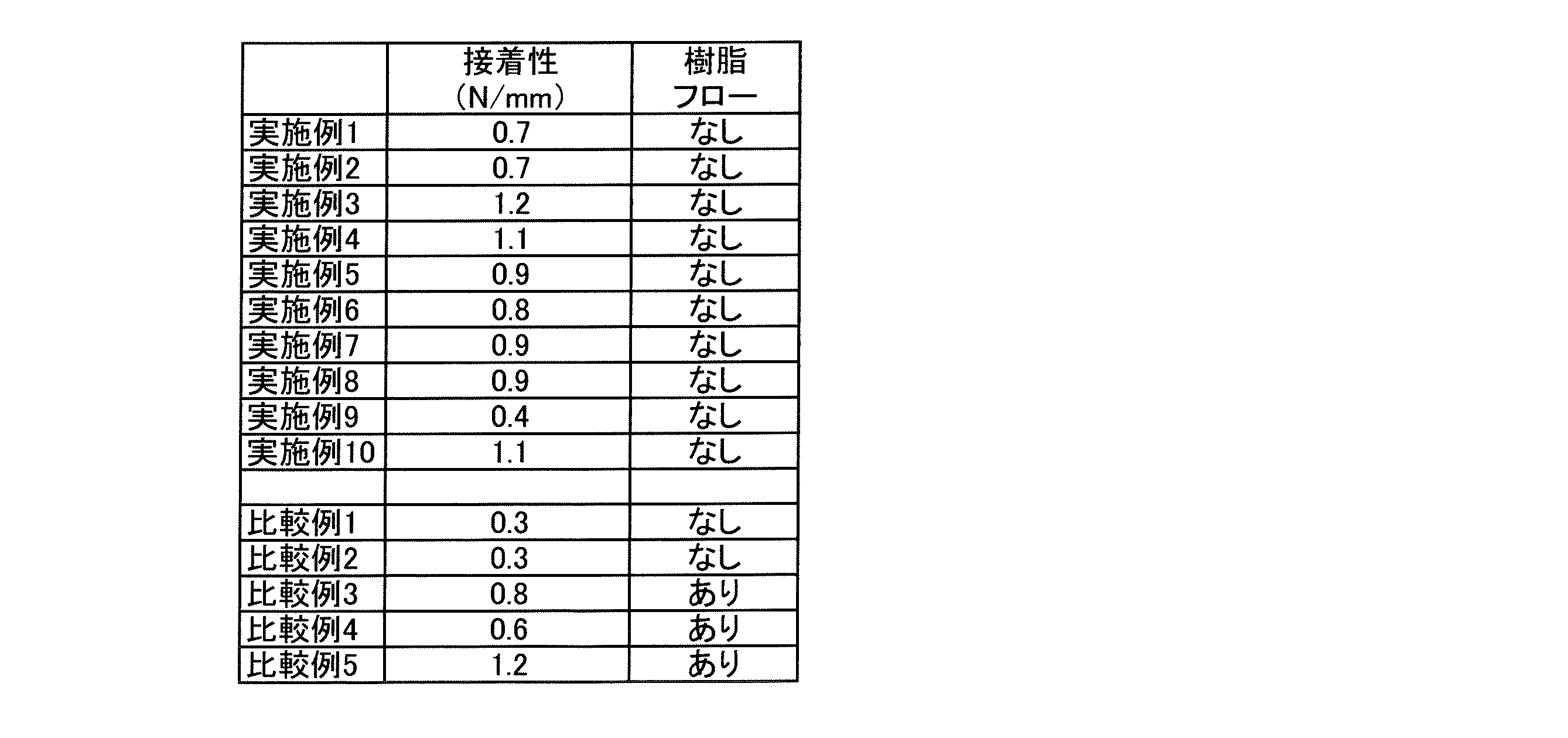
表9に示すように、実施例1~10では、いずれも樹脂フローがなく、熱可塑性液晶ポリマー副構造間の熱圧着性が良好であった。すなわち、得られた熱可塑性液晶ポリマー構造体は、いずれも分子の流動性が抑制されており、これは、目視による外観形状の観察において、分子の流動に由来する変色や変形などが確認されないことと一致している。
さらに、実施例2および4では、導体パターンが形成されていたが、導体パターンが形成されている場合であっても、導体周辺の液晶ポリマーは過度に流動しないため、微細な導体パターンで形成された回路などで回路間クリアランスを要求される場合であっても、その要求を満たすことができる。
また、実施例9では、真空バッチプレスを用いた比較例2よりも低温の熱圧着温度であるだけでなく、比較例2の2倍の枚数を積層したにもかかわらず、実用上問題のない熱圧着性であった。
さらに、脱気乾燥工程を経た熱可塑性液晶ポリマー副構造を予備構造体として一体化した場合、予備加熱時間が実施例3の1/6に過ぎないにもかかわらず、実施例3と同程度の接着性を達成することができた。
さらに、実施例1で得られた熱可塑性液晶ポリマー構造体のSORは1.02であった。また、実施例1~10で得られた熱可塑性液晶ポリマー構造体における最外層の熱可塑性液晶ポリマー要素についての面方向の熱膨張係数の公差は、1ppm/℃以下であった。
一方、真空バッチプレスを用いた比較例1および2では、樹脂フローがなく、分子の過度な流動もなかったけれども、接着強度が合格の範囲ではなかった。比較例1は実施例6と同じ熱圧着温度、比較例2では、実施例6よりも高い熱圧着温度であるにもかかわらず、真空バッチプレスでは、各層が100μmの熱可塑性液晶ポリマーフィルムを積層する場合には、充分な接着強度を達成することができなかった。
比較例3および4では、熱圧着温度を比較例2よりも高くしたため、接着強度は合格の範囲に入ったが、その一方で、樹脂フローが発生した。
比較例5では、オートクレーブ積層プレスにおける熱圧着時の圧力が3MPa(ゲージ圧)であるため、接着強度は合格の範囲に入ったが、その一方で、樹脂フローが発生した。
また、比較例5の結果を参酌すると、予備加熱を行わずにオートクレーブからの加熱加圧ガスにより高圧下で熱圧着した場合、分子の過度な流動により、樹脂フローが発生することが予測される。
また、比較例5の結果を参酌すると、予備加熱を行わずにオートクレーブからの加熱加圧ガスにより高圧下で熱圧着した場合、分子の過度な流動により、樹脂フローが発生することが予測される。
本発明の製造方法は樹脂フローの発生が抑制された熱可塑性液晶ポリマー構造体を得るのに有用であり、得られた熱可塑性液晶ポリマー構造体は、電気・電子分野や、事務機器・精密機器分野、パワー半導体分野などにおいて用いられる部品として有効に用いることができる。
以上のとおり、本発明の好適な実施形態を説明したが、本発明の趣旨を逸脱しない範囲で、種々の追加、変更または削除が可能であり、そのようなものも本発明の範囲内に含まれる。
1…バギングフィルム
2…通気性シート
3…トッププレート
4a,4b…離型材
5…予備積層体
6…キャリアプレート
7…バキュームノズル
8…バキュームシーラントテープ
9…オートクレーブ
2…通気性シート
3…トッププレート
4a,4b…離型材
5…予備積層体
6…キャリアプレート
7…バキュームノズル
8…バキュームシーラントテープ
9…オートクレーブ
Claims (11)
- オートクレーブを用いて複数の熱可塑性液晶ポリマー副構造が一体化された熱可塑性液晶ポリマー構造体を製造する方法であって、
複数の熱可塑性液晶ポリマー副構造が重ね合わせられた予備積層体をバギングフィルムで被覆し、前記バギングフィルムの端部をシールする封入工程と、
前記バギングフィルム内部の排気を行い、予備加熱温度である第1温度まで昇温を行う昇温工程と、
前記第1温度を起点として、オートクレーブの内圧を2.8MPa以下(ゲージ圧)の所望の圧力へ昇圧するとともに、熱圧着温度である第2温度へ昇温する熱圧着工程と、
を少なくとも備える熱可塑性液晶ポリマー構造体の製造方法。 - 請求項1に記載の熱可塑性液晶ポリマー構造体の製造方法であって、予備積層体の中で最も融点の低い熱可塑性液晶ポリマー要素の融点をMLとした場合、第1温度が(ML-150)℃~(ML-50)℃の範囲である、製造方法。
- 請求項1または2に記載の熱可塑性液晶ポリマー構造体の製造方法であって、第1温度での保持時間が1~120分間である、製造方法。
- 請求項1~3のいずれか一項に記載の熱可塑性液晶ポリマー構造体の製造方法であって、第1温度への昇温速度が、1~10℃/minである、製造方法。
- 請求項1~4のいずれか一項に記載の熱可塑性液晶ポリマー構造体の製造方法であって、予備積層体の中で最も融点の高い熱可塑性液晶ポリマー要素の融点をMHとした場合、第2温度が、(MH-30)℃~(MH+10)℃の範囲である、製造方法。
- 請求項1~5のいずれか一項に記載の熱可塑性液晶ポリマー構造体の製造方法であって、第2温度での保持時間が15~60分間である、製造方法。
- 請求項1~6のいずれか一項に記載の熱可塑性液晶ポリマー構造体の製造方法であって、第2温度への昇温速度は、2~20℃/minである、製造方法。
- 請求項1~7のいずれか一項に記載の熱可塑性液晶ポリマー構造体の製造方法であって、昇温工程に先立って、脱気乾燥工程が行われる、製造方法。
- 請求項8に記載の製造方法であって、脱気乾燥工程後の熱可塑性液晶ポリマーフィルムの水分率が380ppm以下である、製造方法。
- 請求項8または9に記載の熱可塑性液晶ポリマー構造体の製造方法であって、第1温度での保持時間が1~20分間である、製造方法。
- 請求項1~10のいずれか一項に記載の製造方法であって、昇温工程後の予備加熱対象の熱可塑性液晶ポリマー要素の水分率が380ppm以下である、製造方法。
Priority Applications (2)
| Application Number | Priority Date | Filing Date | Title |
|---|---|---|---|
| CN201980068216.2A CN112867593B (zh) | 2018-10-18 | 2019-10-08 | 热塑性液晶聚合物结构体的制造方法 |
| JP2020510624A JP6743324B1 (ja) | 2018-10-18 | 2019-10-08 | 熱可塑性液晶ポリマー構造体の製造方法 |
Applications Claiming Priority (2)
| Application Number | Priority Date | Filing Date | Title |
|---|---|---|---|
| JP2018196375 | 2018-10-18 | ||
| JP2018-196375 | 2018-10-18 |
Publications (1)
| Publication Number | Publication Date |
|---|---|
| WO2020080190A1 true WO2020080190A1 (ja) | 2020-04-23 |
Family
ID=70283188
Family Applications (1)
| Application Number | Title | Priority Date | Filing Date |
|---|---|---|---|
| PCT/JP2019/039644 Ceased WO2020080190A1 (ja) | 2018-10-18 | 2019-10-08 | 熱可塑性液晶ポリマー構造体の製造方法 |
Country Status (4)
| Country | Link |
|---|---|
| JP (1) | JP6743324B1 (ja) |
| CN (1) | CN112867593B (ja) |
| TW (1) | TWI794550B (ja) |
| WO (1) | WO2020080190A1 (ja) |
Cited By (3)
| Publication number | Priority date | Publication date | Assignee | Title |
|---|---|---|---|---|
| CN116512496A (zh) * | 2023-04-04 | 2023-08-01 | 深圳市信维通信股份有限公司 | 半固化片制备方法及半固化片 |
| WO2023167058A1 (ja) * | 2022-03-02 | 2023-09-07 | 株式会社クラレ | 有機無機クラッド材 |
| DE102023205478A1 (de) * | 2023-06-13 | 2024-12-19 | Zf Friedrichshafen Ag | Verfahren zur herstellung eines halbleitermoduls |
Families Citing this family (2)
| Publication number | Priority date | Publication date | Assignee | Title |
|---|---|---|---|---|
| TWI847057B (zh) * | 2021-09-02 | 2024-07-01 | 復盛應用科技股份有限公司 | 熱塑性複合材的成型方法 |
| CN114025517B (zh) * | 2021-09-24 | 2024-04-12 | 上海航天电子通讯设备研究所 | 一种lcp多层电路板平坦化层压方法及装置 |
Citations (6)
| Publication number | Priority date | Publication date | Assignee | Title |
|---|---|---|---|---|
| JP2011068057A (ja) * | 2009-09-28 | 2011-04-07 | Mitsubishi Rayon Co Ltd | サンドイッチ構造成形物 |
| JP2011513529A (ja) * | 2008-02-29 | 2011-04-28 | ビクトレックス マニュファクチャリング リミテッド | 複合材料 |
| JP2012020521A (ja) * | 2010-07-15 | 2012-02-02 | Mitsubishi Heavy Ind Ltd | 樹脂基複合材の製造方法 |
| JP2013188953A (ja) * | 2012-03-14 | 2013-09-26 | Sekisui Plastics Co Ltd | 繊維強化複合体の製造方法 |
| JP2017128012A (ja) * | 2016-01-19 | 2017-07-27 | 株式会社羽生田鉄工所 | オートクレーブ成形方法、オートクレーブ成形装置及びこれらに用いる成形型の製造方法 |
| WO2018079475A1 (ja) * | 2016-10-26 | 2018-05-03 | 東レ株式会社 | プリプレグ積層体、繊維強化複合材料および繊維強化複合材料の製造方法 |
Family Cites Families (3)
| Publication number | Priority date | Publication date | Assignee | Title |
|---|---|---|---|---|
| US20120202071A1 (en) * | 2009-09-28 | 2012-08-09 | Mitsubhishi Rayon Co., Ltd | Fiber-reinforced composite material |
| CN105637019B (zh) * | 2013-10-03 | 2019-09-10 | 株式会社可乐丽 | 热塑性液晶聚合物膜、电路基板、及它们的制造方法 |
| CN107079594B (zh) * | 2014-11-07 | 2019-08-23 | 株式会社可乐丽 | 电路基板及其制造方法 |
-
2019
- 2019-10-08 JP JP2020510624A patent/JP6743324B1/ja active Active
- 2019-10-08 WO PCT/JP2019/039644 patent/WO2020080190A1/ja not_active Ceased
- 2019-10-08 CN CN201980068216.2A patent/CN112867593B/zh active Active
- 2019-10-17 TW TW108137402A patent/TWI794550B/zh active
Patent Citations (6)
| Publication number | Priority date | Publication date | Assignee | Title |
|---|---|---|---|---|
| JP2011513529A (ja) * | 2008-02-29 | 2011-04-28 | ビクトレックス マニュファクチャリング リミテッド | 複合材料 |
| JP2011068057A (ja) * | 2009-09-28 | 2011-04-07 | Mitsubishi Rayon Co Ltd | サンドイッチ構造成形物 |
| JP2012020521A (ja) * | 2010-07-15 | 2012-02-02 | Mitsubishi Heavy Ind Ltd | 樹脂基複合材の製造方法 |
| JP2013188953A (ja) * | 2012-03-14 | 2013-09-26 | Sekisui Plastics Co Ltd | 繊維強化複合体の製造方法 |
| JP2017128012A (ja) * | 2016-01-19 | 2017-07-27 | 株式会社羽生田鉄工所 | オートクレーブ成形方法、オートクレーブ成形装置及びこれらに用いる成形型の製造方法 |
| WO2018079475A1 (ja) * | 2016-10-26 | 2018-05-03 | 東レ株式会社 | プリプレグ積層体、繊維強化複合材料および繊維強化複合材料の製造方法 |
Cited By (4)
| Publication number | Priority date | Publication date | Assignee | Title |
|---|---|---|---|---|
| WO2023167058A1 (ja) * | 2022-03-02 | 2023-09-07 | 株式会社クラレ | 有機無機クラッド材 |
| CN116512496A (zh) * | 2023-04-04 | 2023-08-01 | 深圳市信维通信股份有限公司 | 半固化片制备方法及半固化片 |
| DE102023205478A1 (de) * | 2023-06-13 | 2024-12-19 | Zf Friedrichshafen Ag | Verfahren zur herstellung eines halbleitermoduls |
| DE102023205478B4 (de) | 2023-06-13 | 2025-01-09 | Zf Friedrichshafen Ag | Verfahren zur herstellung eines halbleitermoduls |
Also Published As
| Publication number | Publication date |
|---|---|
| CN112867593A (zh) | 2021-05-28 |
| TWI794550B (zh) | 2023-03-01 |
| JPWO2020080190A1 (ja) | 2021-02-15 |
| TW202031450A (zh) | 2020-09-01 |
| CN112867593B (zh) | 2022-11-01 |
| JP6743324B1 (ja) | 2020-08-19 |
Similar Documents
| Publication | Publication Date | Title |
|---|---|---|
| JP6743324B1 (ja) | 熱可塑性液晶ポリマー構造体の製造方法 | |
| JP6499584B2 (ja) | 熱可塑性液晶ポリマーフィルム、回路基板、およびそれらの製造方法 | |
| TWI695655B (zh) | 電路基板之製造方法 | |
| JP2019178326A (ja) | 熱可塑性液晶ポリマーフィルムの製造方法、並びに回路基板及びその製造方法 | |
| JP7024142B2 (ja) | 熱可塑性液晶ポリマーフィルム、積層体、および成形体、ならびにそれらの製造方法 | |
| EP2774945A1 (en) | Thermoplastic liquid crystal polymer film, and laminate and circuit board using same | |
| JP4162321B2 (ja) | 金属箔積層板の製造方法 | |
| KR102776739B1 (ko) | 금속 피복 적층체의 제조 방법 | |
| JP7201371B2 (ja) | 熱可塑性液晶ポリマー多層構造体の製造方法 | |
| KR102324897B1 (ko) | 금속 피복 적층체의 제조 방법 | |
| KR102776738B1 (ko) | 금속 피복 적층체의 제조 방법 | |
| KR20250150559A (ko) | 열가소성 액정 폴리머 필름 및 적층체, 그리고 그들의 제조 방법 | |
| WO2006118211A1 (ja) | 回路基板およびその製造方法 | |
| JP7458396B2 (ja) | 金属張積層体の製造方法 |
Legal Events
| Date | Code | Title | Description |
|---|---|---|---|
| ENP | Entry into the national phase |
Ref document number: 2020510624 Country of ref document: JP Kind code of ref document: A |
|
| 121 | Ep: the epo has been informed by wipo that ep was designated in this application |
Ref document number: 19874483 Country of ref document: EP Kind code of ref document: A1 |
|
| NENP | Non-entry into the national phase |
Ref country code: DE |
|
| 122 | Ep: pct application non-entry in european phase |
Ref document number: 19874483 Country of ref document: EP Kind code of ref document: A1 |