WO2020080138A1 - 地際推定方法、地際推定装置及びプログラム - Google Patents
地際推定方法、地際推定装置及びプログラム Download PDFInfo
- Publication number
- WO2020080138A1 WO2020080138A1 PCT/JP2019/039280 JP2019039280W WO2020080138A1 WO 2020080138 A1 WO2020080138 A1 WO 2020080138A1 JP 2019039280 W JP2019039280 W JP 2019039280W WO 2020080138 A1 WO2020080138 A1 WO 2020080138A1
- Authority
- WO
- WIPO (PCT)
- Prior art keywords
- columnar object
- height
- ground
- columnar
- utility pole
- Prior art date
- Legal status (The legal status is an assumption and is not a legal conclusion. Google has not performed a legal analysis and makes no representation as to the accuracy of the status listed.)
- Ceased
Links
Images




Classifications
-
- G—PHYSICS
- G06—COMPUTING OR CALCULATING; COUNTING
- G06T—IMAGE DATA PROCESSING OR GENERATION, IN GENERAL
- G06T7/00—Image analysis
- G06T7/60—Analysis of geometric attributes
-
- G—PHYSICS
- G06—COMPUTING OR CALCULATING; COUNTING
- G06T—IMAGE DATA PROCESSING OR GENERATION, IN GENERAL
- G06T7/00—Image analysis
- G06T7/60—Analysis of geometric attributes
- G06T7/62—Analysis of geometric attributes of area, perimeter, diameter or volume
-
- G—PHYSICS
- G01—MEASURING; TESTING
- G01B—MEASURING LENGTH, THICKNESS OR SIMILAR LINEAR DIMENSIONS; MEASURING ANGLES; MEASURING AREAS; MEASURING IRREGULARITIES OF SURFACES OR CONTOURS
- G01B11/00—Measuring arrangements characterised by the use of optical techniques
- G01B11/02—Measuring arrangements characterised by the use of optical techniques for measuring length, width or thickness
-
- G—PHYSICS
- G01—MEASURING; TESTING
- G01B—MEASURING LENGTH, THICKNESS OR SIMILAR LINEAR DIMENSIONS; MEASURING ANGLES; MEASURING AREAS; MEASURING IRREGULARITIES OF SURFACES OR CONTOURS
- G01B21/00—Measuring arrangements or details thereof, where the measuring technique is not covered by the other groups of this subclass, unspecified or not relevant
-
- G—PHYSICS
- G01—MEASURING; TESTING
- G01B—MEASURING LENGTH, THICKNESS OR SIMILAR LINEAR DIMENSIONS; MEASURING ANGLES; MEASURING AREAS; MEASURING IRREGULARITIES OF SURFACES OR CONTOURS
- G01B21/00—Measuring arrangements or details thereof, where the measuring technique is not covered by the other groups of this subclass, unspecified or not relevant
- G01B21/02—Measuring arrangements or details thereof, where the measuring technique is not covered by the other groups of this subclass, unspecified or not relevant for measuring length, width, or thickness
-
- G—PHYSICS
- G06—COMPUTING OR CALCULATING; COUNTING
- G06T—IMAGE DATA PROCESSING OR GENERATION, IN GENERAL
- G06T19/00—Manipulating three-dimensional [3D] models or images for computer graphics
-
- G—PHYSICS
- G06—COMPUTING OR CALCULATING; COUNTING
- G06T—IMAGE DATA PROCESSING OR GENERATION, IN GENERAL
- G06T2207/00—Indexing scheme for image analysis or image enhancement
- G06T2207/30—Subject of image; Context of image processing
- G06T2207/30181—Earth observation
- G06T2207/30184—Infrastructure
Definitions
- the present disclosure relates to a surface estimation method, a surface estimation apparatus, and a program for estimating the position of the ground surface (the boundary between the ground surface and the columnar object) when a columnar object such as a utility pole is three-dimensionally modeled using a point cloud or the like.
- a point cloud data measured by a measurement vehicle called MMS for example, refer to Non-Patent Document 1
- MMS a measurement vehicle
- a utility pole 3D model is generated, and its shape, position, and elevation are acquired.
- the utility pole 3D model is a CAD model in which the shape of the utility pole is saved, and information such as the center point and radius of the utility pole cut surface at a fixed height of the utility pole can be acquired. From the 3D model of the utility pole, for example, in order to accurately grasp the position of the building pole of the utility pole, it is necessary to obtain the elevation of the connection surface (ground level) between the utility pole and the ground.
- the utility pole 3D model when the utility pole 3D model is generated, a point cloud is not generated on the utility pole because the vicinity of the utility pole base is shielded by a shield such as a hedge or a guardrail, and the bottom surface of the utility pole 3D model does not always match the ground level.
- a shield such as a hedge or a guardrail
- the bottom surface of the utility pole 3D model does not always match the ground level.
- the 3D model of the utility pole has been generated up to the top surface of the utility pole, the elevation above the ground can be easily calculated using the standard length and the embedded length of the utility pole.
- the utility pole 3D model is not necessarily generated up to the top surface of the utility pole, and in such a case, there is a problem that it is difficult to acquire the altitude at the ground level.
- the present invention in order to solve the above problems, a ground surface estimation method capable of acquiring the altitude of the ground of the utility pole in a short time and with high accuracy even when the base of the utility pole is shielded by a shield at the time of observing the utility pole,
- An object is to provide a surface estimation device and a program.
- the ground surface estimation method uses a height at a position where the horizontal dimension of the columnar shape of a three-dimensional model of a columnar object such as an observed utility pole and the shape defined by the standard are equal.
- the difference in height is calculated, and the height of the shielding portion at the surface of the columnar object is calculated by subtracting the rooting length defined by the standard from the difference in height.
- the surface estimation method is An external data input step in which a three-dimensional model of a columnar object having a shape in which the observed horizontal dimension partially buried in the ground is uniquely defined with respect to height is input, An internal data input step in which the standard shape of the columnar object is input, Obtaining the difference in height at the position where the horizontal dimension of the three-dimensional model and the standard shape of the columnar object are equal, and the standard length embedded in the ground of the columnar object from the difference in height. By subtracting, calculate the length of the shielding portion that was not observed due to the shielding when observing the columnar object, the height above the three-dimensional model and the height of the shielding portion above the ground level of the columnar object. A calculation process for calculating I do.
- the land surface estimation device An external data input unit for inputting the observed three-dimensional model of a columnar object partially buried in the ground, the horizontal dimension of which is uniquely defined with respect to the height, An internal data input unit for inputting a standard shape of the columnar object, Obtaining the difference in height at the position where the horizontal dimension of the three-dimensional model and the standard shape of the columnar object are equal, and the standard length embedded in the ground of the columnar object from the difference in height. By subtracting, calculate the length of the occluded portion that was occluded when observing the columnar object and was not observed, and the height above the three-dimensional model and the length of the occluded part A calculation unit that calculates Equipped with.
- the length of the shielded portion is acquired by comparing the observed three-dimensional model of the utility pole with the stored standard truncated cone shape. Therefore, the present invention provides a ground surface estimation method and a ground surface estimation apparatus that can acquire the altitude of the ground surface of a utility pole in a short time and with high accuracy even if the base of the utility pole is shielded by a shield during observation of the utility pole. You can
- the land surface estimation method is The ground elevation calculated in the calculation step, The known altitude closest to the columnar object, an accessory attached to a predetermined position of the columnar object is detected, and the surface elevation of the columnar object estimated from the height of the detected accessory, and other altitudes Of at least one of the It is preferable to further perform a combination processing step of calculating the combined surface elevation of the columnar objects by combining.
- the calculation unit of the surface estimation apparatus calculateated surface elevation, The known altitude closest to the columnar object, an accessory attached to a predetermined position of the columnar object is detected, and the surface elevation of the columnar object estimated from the height of the detected accessory, and other altitudes Of at least one of the It is preferable to calculate the combined surface elevation of the columnar objects by combining the above.
- the program according to the present invention is a program for causing a computer to function as the above-mentioned ground surface estimation device.
- the surface estimation apparatus according to the present invention can be realized by a computer and a program, and the program can be recorded in a recording medium or provided through a network.
- the present invention provides a ground surface estimation method, a ground surface estimation device, and a program capable of acquiring the altitude of the ground surface of a utility pole in a short time and with high accuracy even if the base of the utility pole is shielded by a shield during the observation of the utility pole.
- FIG. 1 is a flowchart illustrating the land surface estimation method of this embodiment.
- the ground surface estimation method at least one estimation processing of the shielded ground surface is performed (step S01), and processing combining these results, for example, averaging processing is performed (step S02).
- step S01 At least one estimation processing of the shielded ground surface is performed (step S01), and processing combining these results, for example, averaging processing is performed (step S02).
- step S01 At least one estimation processing of the shielded ground surface is performed
- processing combining these results for example, averaging processing is performed (step S02).
- averaging processing is performed (step S02).
- step S01 There are a plurality of methods of the land surface estimation processing performed in step S01. The method will be described below.
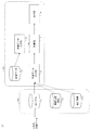
- FIG. 2 is a block diagram illustrating the ground surface estimation device 301 of this embodiment.
- the surface estimation device 301 An external data input unit 11 for inputting a three-dimensional model of an observed columnar object partially buried in the ground, the horizontal dimension of which is uniquely defined with respect to height;
- An internal data input unit 12 for inputting a standard shape of the columnar object, Obtaining the difference in height at the position where the horizontal dimension of the three-dimensional model and the standard shape of the columnar object are equal, and the standard length embedded in the ground of the columnar object from the difference in height.
- the columnar object is, for example, a truncated cone object if the observation target is an electric pole.
- the ground surface estimation apparatus 301 may also include the equipment data 10 in which the standard shape of a truncated cone object such as a utility pole is stored.
- the MMS 100 is an observation vehicle as described in Non-Patent Document 1, and acquires the three-dimensional (XYZ) coordinates of points on the surface of an outdoor structure as three-dimensional point cloud data while traveling on the road.
- the MMS 100 irradiates the surrounding area with a laser beam, acquires the elevation angle and direction of the radiated laser beam, and the direction, distance, and height of the reflection point from the time until the laser beam reflects and returns, and acquires it with GPS.
- the three-dimensional (XYZ) coordinates are acquired based on the position of the self.
- Patent Document 1 describes a facility state detection method for accurately detecting the actual state of a facility such as a telephone pole, a cable, a closure and the like and determining the actual state of the facility as described below.
- the method of Patent Document 1 first, three-dimensional point cloud data corresponding to points on the surface of an outdoor structure is obtained by MMS. Then, the position (XY coordinates) of the electric pole to be inspected is obtained from the stored facility management data (for example, the facility data 10 in FIG. 2), and a predetermined cylindrical space centered on the position is formed, Only the data included in the cylindrical space is selected from the acquired three-dimensional point cloud data.
- an arc is searched for from a plane projection point at an arbitrary height.
- the circle and its center point for each plane projection point are calculated from the arcs detected from the plurality of plane projection points, and the utility pole is stored from the stored facility management data.
- the specification and the circle and the center point calculated for each plane projection point are compared to detect a utility pole (conical trapezoid), and a 3D model I-1 of the utility pole is generated.
- the facility management data stored in the facility data 10 is data when a utility pole is installed, and, for example, the position (coordinates) and type (post length and design strength) of the utility pole are described with the name of the utility pole as a key. Opts data (see http://www.joem.or.jp/2017-3-2.pdf).
- the 3D model I-1 generated by the MMS 100 has the following problems.
- the boundary (ground) between the outdoor structure and the ground is not always visible from the MMS 100.
- guardrails, parked vehicles, embankments, and other shields it is not possible to obtain three-dimensional (XYZ) coordinates of a portion including the ground covered by the shields. In such a case, the MMS 100 alone cannot correctly acquire the ground level elevation of the outdoor structure.
- the ground surface estimation device 301 estimates the ground surface elevation of the outdoor structure as follows.
- the surface estimation device 301 An external data input step in which a three-dimensional model of a columnar object having a shape in which the observed horizontal dimension partially buried in the ground is uniquely defined with respect to height is input, An internal data input step in which the standard shape of the columnar object is input, Obtaining the difference in height at the position where the horizontal dimension of the three-dimensional model and the standard shape of the columnar object are equal, and the standard length embedded in the ground of the columnar object from the difference in height.
- the external data input unit 11 receives the 3D model I-1 of the electric pole shielded by the shield from the MMS 100, for example.
- the internal data input unit 12 receives the information about the utility pole (for example, the standard shape of the utility pole) from the equipment data 10.
- the calculation unit 13 calculates the height o of the shield as shown in FIG.
- utility poles have a 1/75 taper.
- 1/6 of the entire length is buried in the ground.
- the diameter of the lowermost surface of the 3D model I-1 of the electric pole is 18 cm.
- the diameter of the lowermost surface of the 3D model I-1 of the electric pole is smaller than 18 cm. For example, it is 17.25 cm. In this case, the height of the bottom surface of the 3D model I-1 from the ground can be estimated from the difference between the original bottom diameter and the diameter of the bottom surface of the 3D model I-1.
- the estimation method performed by the calculation unit 13 is shown in the flowchart of FIG.
- the flowchart of FIG. 4 is an example of step S01 of FIG.
- FIG. 6 is an image for explaining the estimation method.
- the calculation unit 13 reads the 3D model I-1 of the observed utility pole (step S11).
- the calculation unit 13 analyzes the 3D model I-1 and acquires an array A of diameters from the lowermost surface to the uppermost surface for each constant height of the electric pole (step S12).
- the calculation part 13 acquires the pillar type of the said electric pole from the equipment data 10 based on the center coordinate of the observed electric pole (step S13).
- the calculation unit 13 acquires the standard shape (column length, original diameter (bottom diameter), end diameter (top diameter), and rooting length r) of the relevant pillar type from the equipment data 10 (step S14). . Then, the calculation unit 13 obtains the slope a1 and the intercept b1 of the single regression line ⁇ in FIG. 5 from the column length, the original diameter (bottom diameter), and the end diameter (top diameter) of the relevant pillar type (step S15). . On the other hand, the calculation unit 13 obtains the slope a2 and the intercept b2 of the single regression line ⁇ in FIG. 5 from the array A from the bottom surface to the top surface of the 3D model I-1 (step S16).
- the calculation unit 13 acquires the heights (elevations) of the lowermost surface and the uppermost surface of the 3D model I-1 of the electric pole, and determines a predetermined height, for example, the lowermost surface and the uppermost surface of the 3D model I-1.
- the diameter X1 of the position p1 of the single regression line ⁇ of the middle height (the height obtained by adding t / 2 to the height of the bottom surface, where t is the height difference between the bottom surface and the top surface) is obtained.
- the calculation unit 13 matches the standard bottom surface of the corresponding pillar type with the bottom surface of the 3D model I-1 as shown in FIG. p2 is obtained (step S18).
- the calculation unit 13 subtracts the rooting length r from the height difference h between the positions p1 and p2 to obtain the height o of the shielded portion (step S19, see FIG. 6). Finally, the calculation unit 13 subtracts the height o of the shielding portion from the height (elevation) of the bottom surface of the 3D model I-1 to obtain the surface elevation (step S20).
- FIG. 7 is a diagram for explaining the near-edge estimation method.
- the MMS 100 can acquire vehicle position information I-2 including the position and altitude of the own vehicle by GPS or the like while traveling on the road.
- the external data input unit 11 of the surface estimation device 301 receives the vehicle position information I-2 from the MMS 100.
- the external data input unit 11 of the surface estimation apparatus 301 also receives the 3D model I-1 of the observation pole from the MMS 100.
- the calculation unit 13 uses the altitude of the vehicle position information I-2 received when the MMS 100 is closest to the power pole to calculate the ground altitude of the power pole.
- FIG. 8 is a flow chart for explaining the near-edge estimation method.
- the calculation unit 13 acquires the aforementioned 3D model I-1 from the MMS 100 via the external data input unit 11 (step S30).
- the calculation unit 13 acquires the vehicle position information I-2 from the MMS 100 via the external data input unit 11 (step S31).
- the vehicle position information I-2 includes a data frame C of a vehicle traveling locus (data of vehicle coordinates and altitude at constant time intervals).
- the calculation unit 13 calculates the distance from the center coordinates of the bottom surface of the 3D model I-1 and the vehicle coordinates of the coordinate item of the data frame C, and newly stores it in the data frame C as the coordinate distance item (step S32).
- the calculation unit 13 detects the data frame C (index D) with the smallest distance from these data frames C (step S33).
- the calculation unit 13 searches the data frame C with the index D, acquires the altitude E of the record, and sets it as the ground level altitude (step S34).
- the calculation unit 13 may further subtract the altitude E from the altitude of the bottom surface of the 3D model to obtain the height o of the shielded portion (step S35).
- steps S33 and S44 not only the record with the smallest distance but also the record with the second, third, ..., Small distances are used, and these are averaged to calculate the altitude E, which is used as the surface altitude. Good.
- FIG. 9 is a diagram for explaining the near-edge estimation method.
- the ground surface elevation is estimated by using the attachments or accessories of telephone poles whose heights are set as shown in FIG.
- the MMS 100 can acquire a telephone pole image I-3 with a camera or the like while traveling on the road.
- the external data input unit 11 of the surface estimation apparatus 301 receives the telephone pole image I-3 from the MMS 100.
- the external data input unit 11 of the surface estimation apparatus 301 also receives the 3D model I-1 of the observation pole from the MMS 100.
- the calculating unit 13 superimposes the 3D model I-1 and the telephone pole image I-3, and calculates the ground elevation using an attachment or an accessory.
- the height of the cable mounted on the utility pole is regulated.
- the difference between the length from the lowermost surface of the 3D model I-1 to the height of the cable and the specified value of the height of the cable is defined as the height o of the shielded portion.
- accessories with specified heights such as nameplates
- not only the utility pole attachments but also nearby features whose height is specified by the standard (guardrail etc.) can be used for the near-surface estimation method.
- FIG. 11 is a flow chart for explaining the method of estimating the borderline.
- the calculation unit 13 acquires the telephone pole image I-3 and the 3D model I-1 from the MMS 100 via the external data input unit 11 (steps S40 and S41).
- the calculation unit 13 reads the cable crossing position, the name plate, and other standard heights from the equipment data 10 via the internal data input unit 11 (step S42).
- the calculation unit 13 superimposes the telephone pole image I-3 and the 3D model I-1 (step S43).
- the calculation unit 13 specifies the position in the image of the specific point such as the nameplate from the superimposed image (step S44).
- the calculation unit 13 obtains the altitude of the specific point (crossing position height, nameplate height, etc.) specified in step S44 (step S45).
- the calculation unit 13 subtracts the standard height from the altitude of the specific point to calculate the surface altitude (step S46).
- the calculation unit 13 may perform the combination process of step S02 of FIG.
- the surface elevation calculated in the calculation step (elevation obtained by the surface estimation method 1)
- the known elevation closest to the columnar object (elevation obtained by the surface estimation method 2)
- an accessory attached to a predetermined position of the columnar object is detected, and the height estimated from the detected height of the accessory is detected.
- the “combination” means to calculate an average value, a median value, and other statistical values of the altitudes obtained by the respective surface estimation methods. It should be noted that in the combination processing, altitudes obtained by methods other than the above-mentioned surface estimation methods 1 to 3 may also be used.
- the calculation unit 13 outputs the result of the combination processing to the output unit 14.
- Step S01 Elevation estimated by the surface estimation method 1: 15.949 m (rooting length 2.66 m, distance from the bottom surface of the 3D model to the ground 0.51 m)
- Step S02 The average of the surface elevations obtained in step S01 is calculated. Average altitude above ground: 16.094m
Landscapes
- Physics & Mathematics (AREA)
- Engineering & Computer Science (AREA)
- General Physics & Mathematics (AREA)
- Theoretical Computer Science (AREA)
- Geometry (AREA)
- Computer Vision & Pattern Recognition (AREA)
- Computer Graphics (AREA)
- Computer Hardware Design (AREA)
- General Engineering & Computer Science (AREA)
- Software Systems (AREA)
- Length Measuring Devices By Optical Means (AREA)
- Length Measuring Devices With Unspecified Measuring Means (AREA)
- Processing Or Creating Images (AREA)
- Radar Systems Or Details Thereof (AREA)
Abstract
電柱の観測時に遮蔽物で電柱の根元が遮蔽されていても短時間かつ高精度に電柱の地際の標高を取得できる地際推定方法、地際推定装置及びプログラムを提供することを目的とする。 本発明に係る地際推定方法は、観測した電柱等の柱状物体の3次元モデルの柱状形状と規格によって定められた形状との水平方向の寸法が等しい位置の高さの差分を求め、この高さの差分から規格によって定められた根入れ長を減算することで柱状物体の地際の遮蔽部分の高さを求めることとした。
Description
本開示は、点群等を用いて電柱等の柱状物体を三次元モデル化する際に地際(地面と柱状物体との境目)の位置を推定する地際推定方法、地際推定装置及びプログラムに関する。
MMS(例えば、非特許文献1を参照。)と呼ばれる計測車両により測定された点群データを用いて、電柱の3次元オブジェクト(電柱3Dモデル)を生成し、その形状、位置及び標高を取得する手段がある(例えば、特許文献1を参照。)。電柱3Dモデルは電柱の形状を保存したCADモデルであり、電柱の一定の高さにおける、電柱切断面の中心点、半径などの情報が取得可能である。電柱3Dモデルから、例えば、電柱の建柱位置を正確に把握するためには、電柱と地面との接続面(地際)の標高を取得することが必要となる。
「三菱モービルマッピングシステム高精度GPS移動計測装置」、http://www.mitsubishielectric.co.jp/mms/、https://www.mitsubishielectric.co.jp/mms/pdf/mms.pdf(2018年9月25日検索)
しかしながら、電柱3Dモデル生成時に生け垣やガードレール等の遮蔽物により、電柱根元付近が遮蔽されることで電柱上に点群が生成されず、電柱3Dモデルの最下面が必ずしも地際と一致していないことがある。この場合、電柱3Dモデルが電柱の天面まで生成されていれば、電柱の規格上の長さと根入れ長を用いて地際の標高を容易に算出することができる。しかし、電柱3Dモデルは必ずしも電柱の天面まで生成されている訳ではなく、そのような場合には、地際の標高を取得することが困難という課題がある。
例えば、『地理院地図(国土地理院,http://maps.gsi.go.jp/)』のように、指定した座標における標高を提示するシステムがある。前述のMMS計測等により電柱の中心点の座標を事前に取得しておけば、このようなシステムを用いることにより遮蔽物で電柱の根元が遮蔽されていても地際の標高を取得することが可能である。
しかしながら、MMS計測等による電柱座標の取得に加え、別システムを使用することにより処理が複雑となり処理時間の短縮が困難、さらに、当該地図システムにおける標高精度は場所に依存するため高精度の測定が困難という課題があった。
そこで、本発明は、前記課題を解決するために、電柱の観測時に遮蔽物で電柱の根元が遮蔽されていても短時間かつ高精度に電柱の地際の標高を取得できる地際推定方法、地際推定装置及びプログラムを提供することを目的とする。
上記目的を達成するために、本発明に係る地際推定方法は、観測した電柱等の柱状物体の3次元モデルの柱状形状と規格によって定められた形状との水平方向の寸法が等しい位置の高さの差分を求め、この高さの差分から規格によって定められた根入れ長を減算することで柱状物体の地際の遮蔽部分の高さを求めることとした。
具体的には、本発明に係る地際推定方法は、
観測した、地面に一部が埋設されている水平方向の寸法が高さに対して一意に規定された形状の柱状物体の三次元モデルが入力される外部データ入力工程と、
前記柱状物体の規格形状が入力される内部データ入力工程と、
前記三次元モデルと前記柱状物体の規格形状との水平方向の寸法が等しい位置の高さの差分を取得し、前記高さの差分から前記柱状物体の地面に埋設されている規格上の長さを減算することで、前記柱状物体を観測したときに遮蔽されて観測されなかった遮蔽部分の長さを計算し、前記三次元モデルの高さと前記遮蔽部分の長さより前記柱状物体の地際標高を演算する計算工程と、
を行う。
観測した、地面に一部が埋設されている水平方向の寸法が高さに対して一意に規定された形状の柱状物体の三次元モデルが入力される外部データ入力工程と、
前記柱状物体の規格形状が入力される内部データ入力工程と、
前記三次元モデルと前記柱状物体の規格形状との水平方向の寸法が等しい位置の高さの差分を取得し、前記高さの差分から前記柱状物体の地面に埋設されている規格上の長さを減算することで、前記柱状物体を観測したときに遮蔽されて観測されなかった遮蔽部分の長さを計算し、前記三次元モデルの高さと前記遮蔽部分の長さより前記柱状物体の地際標高を演算する計算工程と、
を行う。
また、本発明に係る地際推定装置は、
観測した、地面に一部が埋設されている水平方向の寸法が高さに対して一意に規定された形状の柱状物体の三次元モデルが入力される外部データ入力部と、
前記柱状物体の規格形状が入力される内部データ入力部と、
前記三次元モデルと前記柱状物体の規格形状との水平方向の寸法が等しい位置の高さの差分を取得し、前記高さの差分から前記柱状物体の地面に埋設されている規格上の長さを減算することで、前記柱状物体を観測したときに遮蔽されて観測されなかった遮蔽部分の長さを計算し、前記三次元モデルの高さと前記遮蔽部分の長さより前記柱状物体の地際標高を演算する計算部と、
を備える。
観測した、地面に一部が埋設されている水平方向の寸法が高さに対して一意に規定された形状の柱状物体の三次元モデルが入力される外部データ入力部と、
前記柱状物体の規格形状が入力される内部データ入力部と、
前記三次元モデルと前記柱状物体の規格形状との水平方向の寸法が等しい位置の高さの差分を取得し、前記高さの差分から前記柱状物体の地面に埋設されている規格上の長さを減算することで、前記柱状物体を観測したときに遮蔽されて観測されなかった遮蔽部分の長さを計算し、前記三次元モデルの高さと前記遮蔽部分の長さより前記柱状物体の地際標高を演算する計算部と、
を備える。
本発明は、観測した電柱の3次元モデルと記憶している規格上の円錐台形状とを比較して遮蔽部分の長さを取得する。従って、本発明は、電柱の観測時に遮蔽物で電柱の根元が遮蔽されていても短時間かつ高精度に電柱の地際の標高を取得できる地際推定方法及び地際推定装置を提供することができる。
さらに、本発明に係る地際推定方法は、
前記計算工程で演算した地際標高と、
前記柱状物体に最も近い既知の標高、前記柱状物体の所定の位置に取り付けられた付属物を検出し、検出した前記付属物の高さから推定した前記柱状物体の地際標高、及びその他の標高のうちの少なくとも1つの標高と、
を組み合わせて前記柱状物体の組み合わせ地際標高を演算する組み合わせ処理工程をさらに行うことが好ましい。
前記計算工程で演算した地際標高と、
前記柱状物体に最も近い既知の標高、前記柱状物体の所定の位置に取り付けられた付属物を検出し、検出した前記付属物の高さから推定した前記柱状物体の地際標高、及びその他の標高のうちの少なくとも1つの標高と、
を組み合わせて前記柱状物体の組み合わせ地際標高を演算する組み合わせ処理工程をさらに行うことが好ましい。
また、本発明に係る地際推定装置の前記計算部は、
演算した地際標高と、
前記柱状物体に最も近い既知の標高、前記柱状物体の所定の位置に取り付けられた付属物を検出し、検出した前記付属物の高さから推定した前記柱状物体の地際標高、及びその他の標高のうちの少なくとも1つの標高と、
を組み合わせて前記柱状物体の組み合わせ地際標高を演算することが好ましい。
演算した地際標高と、
前記柱状物体に最も近い既知の標高、前記柱状物体の所定の位置に取り付けられた付属物を検出し、検出した前記付属物の高さから推定した前記柱状物体の地際標高、及びその他の標高のうちの少なくとも1つの標高と、
を組み合わせて前記柱状物体の組み合わせ地際標高を演算することが好ましい。
他の手法で得られた情報も組み合わせることで地際の標高の推定精度が向上する。
本発明に係るプログラムは、前記地際推定装置としてコンピュータを機能させるためのプログラムである。本発明に係る地際推定装置はコンピュータとプログラムによっても実現でき、プログラムを記録媒体に記録することも、ネットワークを通して提供することも可能である。
本発明は、電柱の観測時に遮蔽物で電柱の根元が遮蔽されていても短時間かつ高精度に電柱の地際の標高を取得できる地際推定方法、地際推定装置及びプログラムを提供することができる。
添付の図面を参照して本発明の実施形態を説明する。以下に説明する実施形態は本発明の実施例であり、本発明は、以下の実施形態に制限されるものではない。なお、本明細書及び図面において符号が同じ構成要素は、相互に同一のものを示すものとする。
図1は、本実施形態の地際推定方法を説明するフローチャートである。地際推定方法は、遮蔽された地際の推定処理を少なくとも1つ行い(ステップS01)、これらの結果を組み合わせた処理、例えば平均化処理を行う(ステップS02)。ステップS01で行う地際推定処理の方法は複数存在する。その方法を以下に説明する。
(地際推定方法1)
図2は、本実施形態の地際推定装置301を説明するブロック図である。地際推定装置301は、
観測した、地面に一部が埋設されている水平方向の寸法が高さに対して一意に規定された形状の柱状物体の三次元モデルが入力される外部データ入力部11と、
前記柱状物体の規格形状が入力される内部データ入力部12と、
前記三次元モデルと前記柱状物体の規格形状との水平方向の寸法が等しい位置の高さの差分を取得し、前記高さの差分から前記柱状物体の地面に埋設されている規格上の長さを減算することで、前記柱状物体を観測したときに遮蔽されて観測されなかった遮蔽部分の長さを計算し、前記三次元モデルの高さと前記遮蔽部分の長さより前記柱状物体の地際標高を演算する計算部13と、
を備える。
柱状物体とは、例えば、観測対象が電柱であれば円錐台物体である。
図2は、本実施形態の地際推定装置301を説明するブロック図である。地際推定装置301は、
観測した、地面に一部が埋設されている水平方向の寸法が高さに対して一意に規定された形状の柱状物体の三次元モデルが入力される外部データ入力部11と、
前記柱状物体の規格形状が入力される内部データ入力部12と、
前記三次元モデルと前記柱状物体の規格形状との水平方向の寸法が等しい位置の高さの差分を取得し、前記高さの差分から前記柱状物体の地面に埋設されている規格上の長さを減算することで、前記柱状物体を観測したときに遮蔽されて観測されなかった遮蔽部分の長さを計算し、前記三次元モデルの高さと前記遮蔽部分の長さより前記柱状物体の地際標高を演算する計算部13と、
を備える。
柱状物体とは、例えば、観測対象が電柱であれば円錐台物体である。
また、地際推定装置301は、電柱などの円錐台物体の規格形状が記憶される設備データ10を備えていてもよい。
MMS100は、非特許文献1に記載されるような観測車両であり、路上を走行しながら屋外構造物の表面上の点の3次元(XYZ)座標を3次元点群データとして取得する。例えば、MMS100は周囲にレーザ照射を行い、照射したレーザ光の仰角や方向、当該レーザ光が反射して戻ってくるまでの時間から反射点の方向、距離、高さを取得し、GPSで取得した自身の位置に基づいて前記3次元(XYZ)座標を取得する。
そして、MMS100は、特許文献1に記載されるような方法で電柱などの3DモデルI-1を生成する。特許文献1には以下のような、電柱、ケーブル、クロージャ等の設備の実際の状態を正確に検出し、その設備の実際の状態を判断する設備状態検出方法が記載されている。特許文献1の方法は、まず、MMSで屋外構造物の表面上の点に対応する3次元点群データを得る。そして、記憶している設備管理データ(例えば、図2の設備データ10でもよい)から検査対象の電柱の位置(XY座標)を得て、その位置を中心とする所定の円柱空間を形成し、取得した3次元点群データの中から当該円柱空間に含まれるデータのみを選抜する。そして、選抜したデータのうち、任意の高さにおける平面投影点から円弧を探し出す。ここで、複数の平面投影点から各々円弧を検出できた場合、複数の平面投影点から検出した円弧から平面投影点毎の円とその中心点を算出し、記憶している設備管理データから電柱の仕様を得て、当該仕様と平面投影点毎に算出した円及び中心点とを比較して電柱(円錐台形)を検出し、当該電柱の3DモデルI-1を生成する。
設備データ10が記憶している設備管理データとは、電柱を設置した際のデータであり、例えば、電柱の名前をキーに電柱の位置(座標)および種別(柱長及び設計強度)などが記載されたOptosデータ(http://www.joem.or.jp/2017-3-2.pdf参照。)である。
設備データ10が記憶している設備管理データとは、電柱を設置した際のデータであり、例えば、電柱の名前をキーに電柱の位置(座標)および種別(柱長及び設計強度)などが記載されたOptosデータ(http://www.joem.or.jp/2017-3-2.pdf参照。)である。
ここで、MMS100が生成する3DモデルI-1には次のような課題がある。MMS100からは常に屋外構造物と地面との境界(地際)が見えるわけではない。ガードレール、駐車車両、盛り土、その他の遮蔽物がある場合、遮蔽物で遮蔽された地際を含む部分の3次元(XYZ)座標を得ることができない。このような場合、MMS100だけでは当該屋外構造物の地際標高を正しく取得できない。
そこで、地際推定装置301は、次のように屋外構造物の地際標高を推定する。
地際推定装置301は、
観測した、地面に一部が埋設されている水平方向の寸法が高さに対して一意に規定された形状の柱状物体の三次元モデルが入力される外部データ入力工程と、
前記柱状物体の規格形状が入力される内部データ入力工程と、
前記三次元モデルと前記柱状物体の規格形状との水平方向の寸法が等しい位置の高さの差分を取得し、前記高さの差分から前記柱状物体の地面に埋設されている規格上の長さを減算することで、前記柱状物体を観測したときに遮蔽されて観測されなかった遮蔽部分の長さを計算し、前記三次元モデルの高さと前記遮蔽部分の長さより前記柱状物体の地際標高を演算する計算工程と、
を行う。
地際推定装置301は、
観測した、地面に一部が埋設されている水平方向の寸法が高さに対して一意に規定された形状の柱状物体の三次元モデルが入力される外部データ入力工程と、
前記柱状物体の規格形状が入力される内部データ入力工程と、
前記三次元モデルと前記柱状物体の規格形状との水平方向の寸法が等しい位置の高さの差分を取得し、前記高さの差分から前記柱状物体の地面に埋設されている規格上の長さを減算することで、前記柱状物体を観測したときに遮蔽されて観測されなかった遮蔽部分の長さを計算し、前記三次元モデルの高さと前記遮蔽部分の長さより前記柱状物体の地際標高を演算する計算工程と、
を行う。
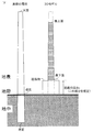
まず、外部データ入力工程では、外部データ入力部11がMMS100から例えば遮蔽物で遮蔽された電柱の3DモデルI-1を受け取る。続いて、内部データ入力工程では、内部データ入力部12が設備データ10から当該電柱についての情報(例えば、当該電柱の規格形状)を受け取る。そして、計算工程では、計算部13が図3のように遮蔽物の高さoを計算する。
例えば、電柱は1/75のテーパを持っている。また標準的な工法として全長の1/6が地中に埋設されている。また柱種ごとに底面の直径、天面の直径も規格によって定められている。
例えば、底面の直径が20cm、柱長が9mであれば、地際における直径は、
0.2[m]-(9[m]×1/6×1/75)=0.18[m]
となり、遮蔽物がない場合には、電柱の3DモデルI-1の最下面の直径は18cmとなる。
一方、遮蔽物により地際が隠蔽された場合、電柱の3DモデルI-1の最下面の直径は、18cmより小さくなる。例えば、17.25cm等である。この場合、本来の底面の直径と3DモデルI-1の最下面の直径との差分から、3DモデルI-1の最下面の地面からの高さを推定することができる。
例えば、底面の直径が20cm、柱長が9mであれば、地際における直径は、
0.2[m]-(9[m]×1/6×1/75)=0.18[m]
となり、遮蔽物がない場合には、電柱の3DモデルI-1の最下面の直径は18cmとなる。
一方、遮蔽物により地際が隠蔽された場合、電柱の3DモデルI-1の最下面の直径は、18cmより小さくなる。例えば、17.25cm等である。この場合、本来の底面の直径と3DモデルI-1の最下面の直径との差分から、3DモデルI-1の最下面の地面からの高さを推定することができる。
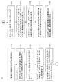
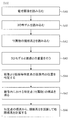
計算部13が行う当該推定方法を図4のフローチャートに示す。図4のフローチャートは、図1のステップS01の一例である。また、図6は、当該推定方法を説明するイメージである。
まず、計算部13は、観測した電柱の3DモデルI-1を読み込む(ステップS11)。計算部13は、当該3DモデルI-1を解析し、電柱の一定の高さ毎の、最下面から最上面までの直径の配列Aを取得する(ステップS12)。
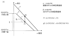
続いて、計算部13は、観測した電柱の中心座標に基づき、設備データ10より、該当電柱の柱種を取得する(ステップS13)。さらに、計算部13は、設備データ10より、該当柱種の規格形状(柱長、元口径(底面直径)、末口径(天面直径)、及び根入れ長r)を取得する(ステップS14)。そして、計算部13は、該当柱種の柱長、元口径(底面直径)、及び末口径(天面直径)から、図5の単回帰直線αの傾きa1と切片b1を求める(ステップS15)。
一方、計算部13は、3DモデルI-1の最下面から最上面までの配列Aから、図5の単回帰直線βの傾きa2と切片b2を求める(ステップS16)。そして、計算部13は、電柱の3DモデルI-1の最下面及び最上面の高さ(標高)を取得し、所定の高さ、例えば、3DモデルI-1の最下面と最上面との間の中央の高さ(最下面と最上面との高さの差をtとして、最下面の高さにt/2を加えた高さ)の単回帰直線βの位置p1の直径X1を求める(ステップS17)。また、計算部13は、図6のように該当柱種の規格形状の底面と3DモデルI-1の最下面とを合わせ、図5のグラフのように単回帰直線αから直径X1となる位置p2を求める(ステップS18)。計算部13は、位置p1と位置p2の高さの差分hから根入れ長rを減算し、遮蔽部分の高さoを求める(ステップS19、図6参照)。
最後に、計算部13は、3DモデルI-1の最下面の高さ(標高)から遮蔽部分の高さoを減算し、地際標高を求める(ステップS20)。
まず、計算部13は、観測した電柱の3DモデルI-1を読み込む(ステップS11)。計算部13は、当該3DモデルI-1を解析し、電柱の一定の高さ毎の、最下面から最上面までの直径の配列Aを取得する(ステップS12)。
続いて、計算部13は、観測した電柱の中心座標に基づき、設備データ10より、該当電柱の柱種を取得する(ステップS13)。さらに、計算部13は、設備データ10より、該当柱種の規格形状(柱長、元口径(底面直径)、末口径(天面直径)、及び根入れ長r)を取得する(ステップS14)。そして、計算部13は、該当柱種の柱長、元口径(底面直径)、及び末口径(天面直径)から、図5の単回帰直線αの傾きa1と切片b1を求める(ステップS15)。
一方、計算部13は、3DモデルI-1の最下面から最上面までの配列Aから、図5の単回帰直線βの傾きa2と切片b2を求める(ステップS16)。そして、計算部13は、電柱の3DモデルI-1の最下面及び最上面の高さ(標高)を取得し、所定の高さ、例えば、3DモデルI-1の最下面と最上面との間の中央の高さ(最下面と最上面との高さの差をtとして、最下面の高さにt/2を加えた高さ)の単回帰直線βの位置p1の直径X1を求める(ステップS17)。また、計算部13は、図6のように該当柱種の規格形状の底面と3DモデルI-1の最下面とを合わせ、図5のグラフのように単回帰直線αから直径X1となる位置p2を求める(ステップS18)。計算部13は、位置p1と位置p2の高さの差分hから根入れ長rを減算し、遮蔽部分の高さoを求める(ステップS19、図6参照)。
最後に、計算部13は、3DモデルI-1の最下面の高さ(標高)から遮蔽部分の高さoを減算し、地際標高を求める(ステップS20)。
(地際推定方法2)
図7は本地際推定方法を説明する図である。図2に示した通り、MMS100は路上を走行しながらGPS等で自車の位置と標高を含む車両位置情報I-2を取得することができる。地際推定装置301の外部データ入力部11は、MMS100からの車両位置情報I-2を受信する。また、地際推定装置301の外部データ入力部11は、MMS100から観測対象の電柱の3DモデルI-1も受信している。計算部13は、MMS100が電柱に最も近接したときに受信した車両位置情報I-2の標高を用いて当該電柱の地際標高を計算する。
図7は本地際推定方法を説明する図である。図2に示した通り、MMS100は路上を走行しながらGPS等で自車の位置と標高を含む車両位置情報I-2を取得することができる。地際推定装置301の外部データ入力部11は、MMS100からの車両位置情報I-2を受信する。また、地際推定装置301の外部データ入力部11は、MMS100から観測対象の電柱の3DモデルI-1も受信している。計算部13は、MMS100が電柱に最も近接したときに受信した車両位置情報I-2の標高を用いて当該電柱の地際標高を計算する。
図8は、本地際推定方法を説明するフローチャートである。まず、計算部13は、外部データ入力部11を介してMMS100より前述した3DモデルI-1を取得する(ステップS30)。計算部13は、外部データ入力部11を介してMMS100より車両位置情報I-2を取得する(ステップS31)。車両位置情報I-2には、車両走行軌跡(一定時間ごとの車両座標及び標高のデータ)のデータフレームCが含まれる。計算部13は、3DモデルI-1の最下面の中心座標とデータフレームCの座標項目の車両座標とから距離を計算し、座標距離項目として新規にデータフレームCへ格納する(ステップS32)。計算部13は、これらのデータフレームCの中から前記距離が最小のデータフレームC(イデックスD)を検出する(ステップS33)。計算部13は、データフレームCをイデックスDで検索し、そのレコードの標高Eを取得し、地際標高とする(ステップS34)。計算部13は、さらに3Dモデルの最下面の標高から標高Eを減算し、遮蔽部分の高さoを求めてもよい(ステップS35)。
なお、ステップS33及びS44において、距離が最小のレコードだけでなく、距離が2番目、3番目、・・・に小さいレコードも利用し、これらを平均して標高Eを算出し、地際標高としてもよい。
なお、ステップS33及びS44において、距離が最小のレコードだけでなく、距離が2番目、3番目、・・・に小さいレコードも利用し、これらを平均して標高Eを算出し、地際標高としてもよい。
(地際推定方法3)
図9は本地際推定方法を説明する図である。本地際推定方法は、図10のように設置する高さが決められている電柱の添架物や付属物を利用して地際標高を推定する。図2に示した通り、MMS100は路上を走行しながらカメラ等で電柱画像I-3を取得することができる。地際推定装置301の外部データ入力部11は、MMS100からの電柱画像I-3を受信する。また、地際推定装置301の外部データ入力部11は、MMS100から観測対象の電柱の3DモデルI-1も受信している。計算部13は、3DモデルI-1と電柱画像I-3とを重畳し、添架物や付属物を利用して地際標高を計算する。
図9は本地際推定方法を説明する図である。本地際推定方法は、図10のように設置する高さが決められている電柱の添架物や付属物を利用して地際標高を推定する。図2に示した通り、MMS100は路上を走行しながらカメラ等で電柱画像I-3を取得することができる。地際推定装置301の外部データ入力部11は、MMS100からの電柱画像I-3を受信する。また、地際推定装置301の外部データ入力部11は、MMS100から観測対象の電柱の3DモデルI-1も受信している。計算部13は、3DモデルI-1と電柱画像I-3とを重畳し、添架物や付属物を利用して地際標高を計算する。
例えば、電柱に添架されているケーブルの高さは規定されている。3DモデルI-1の最下面からケーブルの高さまでの長さとケーブルの高さの規定値との差分を遮蔽部分の高さoとする。ケーブル以外にも、高さが規定されている付属物(銘板等)が本地際推定方法に利用できる。また、電柱付属物のみならず近接地物であって、高さが規格で定められている物(ガードレール等)であれば本地際推定方法に利用できる。
図11は、本地際推定方法を説明するフローチャートである。まず、計算部13は、外部データ入力部11を介してMMS100より電柱画像I-3と3DモデルI-1を取得する(ステップS40、S41)。計算部13は、設備データ10から内部データ入力部11を介してケーブル架渉位置、銘板、その他の規格高さを読み込む(ステップS42)。計算部13は、電柱画像I-3と3DモデルI-1との重畳を行う(ステップS43)。計算部13は、重畳画像より銘板等特定点の画像内の位置を特定する(ステップS44)。計算部13は、ステップS44で特定した特定点(架渉位置高さ、銘板高さ等)の標高を得る(ステップS45)。計算部13は、特定点の標高から規格高さを減算して地際標高を計算する(ステップS46)。
(組み合わせ処理)
計算部13は、図1のステップS02の組み合わせ処理を行ってもよい。組み合わせ処理では、前記計算工程で演算した地際標高(地際推定方法1で取得した標高)と、
前記柱状物体に最も近い既知の標高(地際推定方法2で取得した標高)、前記柱状物体の所定の位置に取り付けられた付属物を検出し、検出した前記付属物の高さから推定した前記柱状物体の地際標高(地際推定方法3で取得した標高)、及びその他の標高のうちの少なくとも1つの標高と、
を組み合わせて前記柱状物体の組み合わせ地際標高を演算する。
計算部13は、図1のステップS02の組み合わせ処理を行ってもよい。組み合わせ処理では、前記計算工程で演算した地際標高(地際推定方法1で取得した標高)と、
前記柱状物体に最も近い既知の標高(地際推定方法2で取得した標高)、前記柱状物体の所定の位置に取り付けられた付属物を検出し、検出した前記付属物の高さから推定した前記柱状物体の地際標高(地際推定方法3で取得した標高)、及びその他の標高のうちの少なくとも1つの標高と、
を組み合わせて前記柱状物体の組み合わせ地際標高を演算する。
ここで「組み合わせ」とは、それぞれの地際推定方法で取得した標高の平均値、中央値その他の統計値を計算することを意味する。なお、組み合わせ処理では、前述した地際推定方法1~3以外で取得した標高も利用してよい。
計算部13は、組み合わせ処理を行った結果を出力部14に出力する。
計算部13は、組み合わせ処理を行った結果を出力部14に出力する。
[ステップS01]
地際推定方法1で推定された地際標高:15.949m(根入れ長2.66m、3Dモデルの最下面から地際までの距離0.51m)
地際推定方法2で推定された地際標高:16.030m(車両から電柱までの距離10.0m)
地際推定方法3で推定された地際標高:16.300m(銘板標高18.50m、規定された銘板高さ2.2m)
[ステップS02]
ステップS01で得られた地際標高の平均を計算する。
地際標高平均値:16.094m
地際推定方法1で推定された地際標高:15.949m(根入れ長2.66m、3Dモデルの最下面から地際までの距離0.51m)
地際推定方法2で推定された地際標高:16.030m(車両から電柱までの距離10.0m)
地際推定方法3で推定された地際標高:16.300m(銘板標高18.50m、規定された銘板高さ2.2m)
[ステップS02]
ステップS01で得られた地際標高の平均を計算する。
地際標高平均値:16.094m
10:設備データ
11:外部データ入力部
12:内部データ入力部
13:計算部
14:出力部
100:MMS
301:地際推定装置
11:外部データ入力部
12:内部データ入力部
13:計算部
14:出力部
100:MMS
301:地際推定装置
Claims (5)
- 観測した、地面に一部が埋設されている水平方向の寸法が高さに対して一意に規定された形状の柱状物体の三次元モデルが入力される外部データ入力工程と、
前記柱状物体の規格形状が入力される内部データ入力工程と、
前記三次元モデルと前記柱状物体の規格形状との水平方向の寸法が等しい位置の高さの差分を取得し、前記高さの差分から前記柱状物体の地面に埋設されている規格上の長さを減算することで、前記柱状物体を観測したときに遮蔽されて観測されなかった遮蔽部分の長さを計算し、前記三次元モデルの高さと前記遮蔽部分の長さより前記柱状物体の地際標高を演算する計算工程と、
を行う地際推定方法。 - 前記計算工程で演算した地際標高と、
前記柱状物体に最も近い既知の標高、前記柱状物体の所定の位置に取り付けられた付属物を検出し、検出した前記付属物の高さから推定した前記柱状物体の地際標高、及びその他の標高のうちの少なくとも1つの標高と、
を組み合わせて前記柱状物体の組み合わせ地際標高を演算する組み合わせ処理工程をさらに行うことを特徴とする請求項1に記載の地際推定方法。 - 観測した、地面に一部が埋設されている水平方向の寸法が高さに対して一意に規定された形状の柱状物体の三次元モデルが入力される外部データ入力部と、
前記柱状物体の規格形状が入力される内部データ入力部と、
前記三次元モデルと前記柱状物体の規格形状との水平方向の寸法が等しい位置の高さの差分を取得し、前記高さの差分から前記柱状物体の地面に埋設されている規格上の長さを減算することで、前記柱状物体を観測したときに遮蔽されて観測されなかった遮蔽部分の長さを計算し、前記三次元モデルの高さと前記遮蔽部分の長さより前記柱状物体の地際標高を演算する計算部と、
を備える地際推定装置。 - 前記計算部は、
演算した地際標高と、
前記柱状物体に最も近い既知の標高、前記柱状物体の所定の位置に取り付けられた付属物を検出し、検出した前記付属物の高さから推定した前記柱状物体の地際標高、及びその他の標高のうちの少なくとも1つの標高と、
を組み合わせて前記柱状物体の組み合わせ地際標高を演算することを特徴とする請求項3に記載の地際推定装置。 - 請求項3又は4に記載の地際推定装置としてコンピュータを機能させるためのプログラム。
Priority Applications (1)
| Application Number | Priority Date | Filing Date | Title |
|---|---|---|---|
| US17/282,952 US11715225B2 (en) | 2018-10-18 | 2019-10-04 | Ground intersection estimating method, ground intersection estimating device, and program |
Applications Claiming Priority (2)
| Application Number | Priority Date | Filing Date | Title |
|---|---|---|---|
| JP2018-196311 | 2018-10-18 | ||
| JP2018196311A JP7052670B2 (ja) | 2018-10-18 | 2018-10-18 | 地際推定方法、地際推定装置及びプログラム |
Publications (1)
| Publication Number | Publication Date |
|---|---|
| WO2020080138A1 true WO2020080138A1 (ja) | 2020-04-23 |
Family
ID=70283095
Family Applications (1)
| Application Number | Title | Priority Date | Filing Date |
|---|---|---|---|
| PCT/JP2019/039280 Ceased WO2020080138A1 (ja) | 2018-10-18 | 2019-10-04 | 地際推定方法、地際推定装置及びプログラム |
Country Status (3)
| Country | Link |
|---|---|
| US (1) | US11715225B2 (ja) |
| JP (1) | JP7052670B2 (ja) |
| WO (1) | WO2020080138A1 (ja) |
Citations (2)
| Publication number | Priority date | Publication date | Assignee | Title |
|---|---|---|---|---|
| JP2012105416A (ja) * | 2010-11-09 | 2012-05-31 | Chugoku Electric Power Co Inc:The | 電柱高さ情報出力装置、コンピュータプログラム、および電柱高さ情報表示方法 |
| JP2015078849A (ja) * | 2013-10-15 | 2015-04-23 | 日本電信電話株式会社 | 設備状態検出方法およびその装置 |
Family Cites Families (5)
| Publication number | Priority date | Publication date | Assignee | Title |
|---|---|---|---|---|
| JP6114052B2 (ja) * | 2013-02-13 | 2017-04-12 | 日本電信電話株式会社 | 点群解析処理装置及び点群解析処理プログラム |
| US9830681B2 (en) * | 2014-01-31 | 2017-11-28 | Hover Inc. | Multi-dimensional model dimensioning and scale error correction |
| JP6186305B2 (ja) * | 2014-05-28 | 2017-08-23 | 日本電信電話株式会社 | たわみ推定装置、及びプログラム |
| WO2016139819A1 (ja) * | 2015-03-03 | 2016-09-09 | 株式会社岩崎 | 地盤形状推定プログラム、地盤形状推定装置および地盤形状推定方法 |
| WO2018159468A1 (ja) * | 2017-02-28 | 2018-09-07 | Necソリューションイノベータ株式会社 | 建築物高さ算出装置、建築物高さ算出方法、及びコンピュータ読み取り可能な記録媒体 |
-
2018
- 2018-10-18 JP JP2018196311A patent/JP7052670B2/ja active Active
-
2019
- 2019-10-04 WO PCT/JP2019/039280 patent/WO2020080138A1/ja not_active Ceased
- 2019-10-04 US US17/282,952 patent/US11715225B2/en active Active
Patent Citations (2)
| Publication number | Priority date | Publication date | Assignee | Title |
|---|---|---|---|---|
| JP2012105416A (ja) * | 2010-11-09 | 2012-05-31 | Chugoku Electric Power Co Inc:The | 電柱高さ情報出力装置、コンピュータプログラム、および電柱高さ情報表示方法 |
| JP2015078849A (ja) * | 2013-10-15 | 2015-04-23 | 日本電信電話株式会社 | 設備状態検出方法およびその装置 |
Also Published As
| Publication number | Publication date |
|---|---|
| US11715225B2 (en) | 2023-08-01 |
| JP7052670B2 (ja) | 2022-04-12 |
| US20210374984A1 (en) | 2021-12-02 |
| JP2020063991A (ja) | 2020-04-23 |
Similar Documents
| Publication | Publication Date | Title |
|---|---|---|
| JP6761828B2 (ja) | 柱状物体状態検出装置、柱状物体状態検出方法、柱状物体状態検出処理プログラム | |
| JP6531051B2 (ja) | 設備状態検出方法および装置 | |
| JP6692320B2 (ja) | 設備状態検出装置およびプログラム | |
| US10191183B2 (en) | Method of constructing digital terrain model | |
| JP7074043B2 (ja) | 設備状態検出装置、設備状態検出方法、及びプログラム | |
| US9552669B2 (en) | System, apparatus, and method for utilizing geographic information systems | |
| KR102357109B1 (ko) | 시공중 터널 막장면 상태평가 시스템 | |
| KR101938402B1 (ko) | 사각지대 지형지물에 대한 수치도화 이미지 합성처리시스템 | |
| US20120150573A1 (en) | Real-time site monitoring design | |
| CN109556569B (zh) | 地形图测绘方法及装置 | |
| JP2020165717A (ja) | 点群データ処理方法および点群データ処理装置 | |
| JP6465421B1 (ja) | 構造物変状検出装置 | |
| JP2014163707A (ja) | 道路変状検出装置、道路変状検出方法及びプログラム | |
| JP2015096824A (ja) | 計測点高付与システム、計測点高付与方法および計測点高付与プログラム | |
| Tang et al. | Surveying, geomatics, and 3D reconstruction | |
| KR101323971B1 (ko) | 모바일 맵핑 시스템을 이용한 터널 정보 자동 취득 방법 | |
| JP6793140B2 (ja) | 設備状態検出装置、設備状態検出方法、設備状態検出処理プログラム | |
| JP5602779B2 (ja) | 現場見取図作成システムおよびレーザ計測装置 | |
| JP2010249709A (ja) | 断面計測装置、断面計測方法および断面計測プログラム | |
| KR100780603B1 (ko) | 이동형 사진측량 시스템에서의 라인 레이저를 이용한시설물의 위치 파악 방법 | |
| JP2017218792A (ja) | 施工管理装置および施工管理方法 | |
| JP7052670B2 (ja) | 地際推定方法、地際推定装置及びプログラム | |
| KR101231007B1 (ko) | 해저의 지형 정보를 이용하여 해저 영상을 모자이킹하기 위한 장치 및 그 방법 | |
| JP2023108245A (ja) | 窪み計測装置、窪み計測方法、及び窪み計測プログラム | |
| JP7409517B2 (ja) | 3d点群の座標を変換する装置、方法及びプログラム |
Legal Events
| Date | Code | Title | Description |
|---|---|---|---|
| 121 | Ep: the epo has been informed by wipo that ep was designated in this application |
Ref document number: 19874315 Country of ref document: EP Kind code of ref document: A1 |
|
| NENP | Non-entry into the national phase |
Ref country code: DE |
|
| 122 | Ep: pct application non-entry in european phase |
Ref document number: 19874315 Country of ref document: EP Kind code of ref document: A1 |