WO2020075833A1 - ガラスユニット - Google Patents
ガラスユニット Download PDFInfo
- Publication number
- WO2020075833A1 WO2020075833A1 PCT/JP2019/040141 JP2019040141W WO2020075833A1 WO 2020075833 A1 WO2020075833 A1 WO 2020075833A1 JP 2019040141 W JP2019040141 W JP 2019040141W WO 2020075833 A1 WO2020075833 A1 WO 2020075833A1
- Authority
- WO
- WIPO (PCT)
- Prior art keywords
- glass
- glass plate
- cover
- unit according
- adhesive
- Prior art date
Links
Images


Classifications
-
- E—FIXED CONSTRUCTIONS
- E06—DOORS, WINDOWS, SHUTTERS, OR ROLLER BLINDS IN GENERAL; LADDERS
- E06B—FIXED OR MOVABLE CLOSURES FOR OPENINGS IN BUILDINGS, VEHICLES, FENCES OR LIKE ENCLOSURES IN GENERAL, e.g. DOORS, WINDOWS, BLINDS, GATES
- E06B3/00—Window sashes, door leaves, or like elements for closing wall or like openings; Layout of fixed or moving closures, e.g. windows in wall or like openings; Features of rigidly-mounted outer frames relating to the mounting of wing frames
- E06B3/66—Units comprising two or more parallel glass or like panes permanently secured together
- E06B3/677—Evacuating or filling the gap between the panes ; Equilibration of inside and outside pressure; Preventing condensation in the gap between the panes; Cleaning the gap between the panes
-
- C—CHEMISTRY; METALLURGY
- C03—GLASS; MINERAL OR SLAG WOOL
- C03C—CHEMICAL COMPOSITION OF GLASSES, GLAZES OR VITREOUS ENAMELS; SURFACE TREATMENT OF GLASS; SURFACE TREATMENT OF FIBRES OR FILAMENTS MADE FROM GLASS, MINERALS OR SLAGS; JOINING GLASS TO GLASS OR OTHER MATERIALS
- C03C27/00—Joining pieces of glass to pieces of other inorganic material; Joining glass to glass other than by fusing
- C03C27/06—Joining glass to glass by processes other than fusing
- C03C27/10—Joining glass to glass by processes other than fusing with the aid of adhesive specially adapted for that purpose
-
- E—FIXED CONSTRUCTIONS
- E06—DOORS, WINDOWS, SHUTTERS, OR ROLLER BLINDS IN GENERAL; LADDERS
- E06B—FIXED OR MOVABLE CLOSURES FOR OPENINGS IN BUILDINGS, VEHICLES, FENCES OR LIKE ENCLOSURES IN GENERAL, e.g. DOORS, WINDOWS, BLINDS, GATES
- E06B3/00—Window sashes, door leaves, or like elements for closing wall or like openings; Layout of fixed or moving closures, e.g. windows in wall or like openings; Features of rigidly-mounted outer frames relating to the mounting of wing frames
- E06B3/66—Units comprising two or more parallel glass or like panes permanently secured together
- E06B3/6612—Evacuated glazing units
-
- E—FIXED CONSTRUCTIONS
- E06—DOORS, WINDOWS, SHUTTERS, OR ROLLER BLINDS IN GENERAL; LADDERS
- E06B—FIXED OR MOVABLE CLOSURES FOR OPENINGS IN BUILDINGS, VEHICLES, FENCES OR LIKE ENCLOSURES IN GENERAL, e.g. DOORS, WINDOWS, BLINDS, GATES
- E06B3/00—Window sashes, door leaves, or like elements for closing wall or like openings; Layout of fixed or moving closures, e.g. windows in wall or like openings; Features of rigidly-mounted outer frames relating to the mounting of wing frames
- E06B3/66—Units comprising two or more parallel glass or like panes permanently secured together
- E06B3/6617—Units comprising two or more parallel glass or like panes permanently secured together one of the panes being larger than another
-
- E—FIXED CONSTRUCTIONS
- E06—DOORS, WINDOWS, SHUTTERS, OR ROLLER BLINDS IN GENERAL; LADDERS
- E06B—FIXED OR MOVABLE CLOSURES FOR OPENINGS IN BUILDINGS, VEHICLES, FENCES OR LIKE ENCLOSURES IN GENERAL, e.g. DOORS, WINDOWS, BLINDS, GATES
- E06B3/00—Window sashes, door leaves, or like elements for closing wall or like openings; Layout of fixed or moving closures, e.g. windows in wall or like openings; Features of rigidly-mounted outer frames relating to the mounting of wing frames
- E06B3/66—Units comprising two or more parallel glass or like panes permanently secured together
- E06B3/663—Elements for spacing panes
- E06B3/66304—Discrete spacing elements, e.g. for evacuated glazing units
-
- E—FIXED CONSTRUCTIONS
- E06—DOORS, WINDOWS, SHUTTERS, OR ROLLER BLINDS IN GENERAL; LADDERS
- E06B—FIXED OR MOVABLE CLOSURES FOR OPENINGS IN BUILDINGS, VEHICLES, FENCES OR LIKE ENCLOSURES IN GENERAL, e.g. DOORS, WINDOWS, BLINDS, GATES
- E06B3/00—Window sashes, door leaves, or like elements for closing wall or like openings; Layout of fixed or moving closures, e.g. windows in wall or like openings; Features of rigidly-mounted outer frames relating to the mounting of wing frames
- E06B3/66—Units comprising two or more parallel glass or like panes permanently secured together
- E06B3/67—Units comprising two or more parallel glass or like panes permanently secured together characterised by additional arrangements or devices for heat or sound insulation or for controlled passage of light
-
- E—FIXED CONSTRUCTIONS
- E06—DOORS, WINDOWS, SHUTTERS, OR ROLLER BLINDS IN GENERAL; LADDERS
- E06B—FIXED OR MOVABLE CLOSURES FOR OPENINGS IN BUILDINGS, VEHICLES, FENCES OR LIKE ENCLOSURES IN GENERAL, e.g. DOORS, WINDOWS, BLINDS, GATES
- E06B3/00—Window sashes, door leaves, or like elements for closing wall or like openings; Layout of fixed or moving closures, e.g. windows in wall or like openings; Features of rigidly-mounted outer frames relating to the mounting of wing frames
- E06B3/66—Units comprising two or more parallel glass or like panes permanently secured together
- E06B3/677—Evacuating or filling the gap between the panes ; Equilibration of inside and outside pressure; Preventing condensation in the gap between the panes; Cleaning the gap between the panes
- E06B3/6775—Evacuating or filling the gap during assembly
-
- Y—GENERAL TAGGING OF NEW TECHNOLOGICAL DEVELOPMENTS; GENERAL TAGGING OF CROSS-SECTIONAL TECHNOLOGIES SPANNING OVER SEVERAL SECTIONS OF THE IPC; TECHNICAL SUBJECTS COVERED BY FORMER USPC CROSS-REFERENCE ART COLLECTIONS [XRACs] AND DIGESTS
- Y02—TECHNOLOGIES OR APPLICATIONS FOR MITIGATION OR ADAPTATION AGAINST CLIMATE CHANGE
- Y02A—TECHNOLOGIES FOR ADAPTATION TO CLIMATE CHANGE
- Y02A30/00—Adapting or protecting infrastructure or their operation
- Y02A30/24—Structural elements or technologies for improving thermal insulation
- Y02A30/249—Glazing, e.g. vacuum glazing
-
- Y—GENERAL TAGGING OF NEW TECHNOLOGICAL DEVELOPMENTS; GENERAL TAGGING OF CROSS-SECTIONAL TECHNOLOGIES SPANNING OVER SEVERAL SECTIONS OF THE IPC; TECHNICAL SUBJECTS COVERED BY FORMER USPC CROSS-REFERENCE ART COLLECTIONS [XRACs] AND DIGESTS
- Y02—TECHNOLOGIES OR APPLICATIONS FOR MITIGATION OR ADAPTATION AGAINST CLIMATE CHANGE
- Y02B—CLIMATE CHANGE MITIGATION TECHNOLOGIES RELATED TO BUILDINGS, e.g. HOUSING, HOUSE APPLIANCES OR RELATED END-USER APPLICATIONS
- Y02B80/00—Architectural or constructional elements improving the thermal performance of buildings
- Y02B80/22—Glazing, e.g. vaccum glazing
Definitions
- the present invention relates to a glass unit and a method for manufacturing the glass unit.
- glass units made of double glazing have been widely used for window glass of buildings.
- the glass unit has an internal space formed between two or more glass plates, and is intended to enhance the heat insulating property in the room.
- a through hole is formed in one of the glass plates, and after decompressing the internal space through this through hole, the through hole is closed by a glass cover. At this time, the contact portion between the inner peripheral edge of the through hole and the cover is irradiated with laser light, and thereby the cover is joined to the through hole.
- the glass cover is locally heated by the irradiation of laser light, which may cause the cover to crack. Further, since the laser light is emitted, there is a problem that the device becomes large.
- the present invention has been made to solve this problem, and an object of the present invention is to provide a glass unit that can be easily manufactured while preventing the cover from cracking, and a method for manufacturing the glass unit.
- Item 1 A first glass plate having a through hole formed therein; A second glass plate facing the first glass plate at a predetermined interval and forming an internal space between the first glass plate and the second glass plate; A sealing material for sealing a gap between the first glass plate and the second glass plate, A cover for closing the through hole, An adhesive for fixing the cover to the first glass plate, With The internal space is decompressed so as to be in a vacuum state, or a predetermined gas is injected into the internal space, A glass unit in which the first glass plate and the cover are fixed by the adhesive.
- the through hole has a small diameter portion and a large diameter portion continuous in the axial direction, The small diameter portion is arranged on the internal space side, Item 2.
- Item 3 The cover is housed in the large diameter portion, Item 3.
- Item 4 The cover is housed in the large diameter portion, Item 2.
- Item 5. The glass unit according to any one of Items 2 to 4, wherein the large diameter portion has an inner diameter of 5 mm or more and 15 mm or less.
- Item 6. The glass unit according to any one of Items 2 to 5, wherein the difference in diameter between the small diameter portion and the large diameter portion is 3 to 20 mm.
- Item 7. The glass unit according to any one of Items 2 to 6, wherein a difference between the depth of the large diameter portion and the thickness of the cover is 0.4 mm or more and 0.7 mm or less.
- Item 8 The glass unit according to any one of Items 1 to 8, wherein the adhesive contains a low melting point glass.
- Item 9 The glass unit according to any one of Items 1 to 8, wherein the difference between the coefficient of thermal expansion of the first glass plate and the coefficient of thermal expansion of the adhesive is 20 ⁇ 10 ⁇ 7 / ° C. or less.
- the cover is made of glass, Item 10.
- the glass unit according to any one of Items 1 to 9, wherein the cover and the first glass plate have the same coefficient of thermal expansion.
- Item 11 Further comprising an intermediate film laminated on the first glass plate and a third glass plate, Item 11.
- Item 12 The glass unit according to any one of Items 1 to 8, wherein the adhesive contains a bismuth-based low melting point glass.
- Item 13 The glass unit according to Item 10, wherein the adhesive is amorphous.
- Item 14 The glass unit according to Item 10, wherein the adhesive is crystalline.
- Item 15 The glass unit according to Item 12, wherein the encapsulating material is formed of an amorphous low melting point glass.
- Item 16 The glass unit according to Item 12, wherein the sealing material and the adhesive are formed of metal solder.
- Item 17 The glass unit according to any one of Items 11 to 14, wherein at least one of the first glass plate and the second glass plate is formed of tempered glass.
- Item 18 The glass unit according to Item 17, wherein the second glass plate is formed of tempered glass.
- Item 19 The glass unit according to Item 17 or 18, wherein the tempered glass is chemically tempered glass.
- Item 20 A peripheral member attached to the peripheral edges of the first glass plate and the second glass plate, the first part being in contact with the first glass plate, the second part being in contact with the second glass plate, and the first part. And a peripheral member formed in a U-shaped cross section having a connecting portion connecting the second portion, Item 20.
- Item 21 A peripheral member attached to the peripheral edges of the first glass plate and the second glass plate, the first part being in contact with the first glass plate, the second part being in contact with the second glass plate, and the first part. And a peripheral member formed in a U-shaped cross section having a connecting portion connecting the second portion, Item 20.
- Item 22 A step of preparing a first glass plate in which a through hole having a small diameter portion and a large diameter portion continuous in the axial direction is formed, Arranging the second glass plate at a predetermined interval from the first glass plate so as to face the small diameter portion side of the first glass plate, Disposing a sealing material in a gap between the peripheral edges of the first glass plate and the second glass plate; A step of disposing a cover so as to block the through hole via the adhesive so that an adhesive is disposed in a step between the large diameter portion and the small diameter portion.
- a method of manufacturing a glass unit comprising:
- Item 23 The method for manufacturing a glass unit according to Item 22, wherein the step of depressurizing the internal space is started in the process of cooling the sealing material.
- the cover is housed in the large diameter portion, After cooling the softened adhesive, the surface of the cover is arranged at a position substantially flush with the surface of the first glass plate or at a position recessed from the surface of the first glass plate.
- Item 25 Prior to the step of disposing the weight, a step of disposing a protective plate covering the cover is further provided, Item 25.
- Item 26 The method of manufacturing a glass unit according to Item 25, wherein the protective plate is quartz glass.
- Item 27 The method for manufacturing a glass unit according to any one of Items 22 to 26, wherein the adhesive is arranged in the step in a discontinuous shape having at least one gap before heating.
- Item 28 The method for manufacturing a glass unit according to any one of Items 22 to 27, wherein the adhesive is bismuth-based solder.
- Item 29. 29. The method for manufacturing a glass unit according to any one of Items 22 to 28, wherein the cover is placed on the first glass plate after the adhesive is attached to the cover.
- Item 30 The method for manufacturing a glass unit according to item 29, wherein the adhesive is attached to the cover by calcination.
- Item 31 The thickness of the adhesive is 0.2 mm or less, Item 31.
- FIG. It is a top view which shows an example of the glass unit which concerns on this invention. It is sectional drawing of FIG. It is a top view which shows the example of the cover by which the adhesive agent was arrange
- FIG. 1 is a plan view of a glass unit according to this embodiment
- FIG. 2 is a sectional view of FIG.
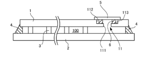
- the glass unit according to the present embodiment has two rectangular glass plates, that is, a first glass plate 1 and a second glass plate 2.
- the second glass plate 2 shown on the lower side in FIG. 2 is formed to be slightly larger than the first glass plate 1.
- a plurality of spacers 3 are arranged between the glass plates 1 and 2, and a space having a predetermined interval is formed between the glass plates 1 and 2 by the spacers 3.
- the gap between the peripheral edges of both the glass plates 1 and 2 is sealed by the sealing material 4, whereby a sealed internal space 100 is formed between the glass plates 1 and 2. Furthermore, a through hole 11 is formed in the first glass plate 1, and a plate-shaped cover 5 that closes the through hole 11 is provided. The cover 5 is fixed to the first glass plate 1 with an adhesive 6.
- each member will be described.
- First glass plate and second glass plate> The material forming the first glass plate 1 is not particularly limited, and a known glass plate can be used. Depending on the application, for example, template glass, frosted glass having a light diffusion function by surface treatment, reticulated glass, lined glass plate, tempered glass, double tempered glass, low reflection glass, high transmission glass plate, ceramic glass plate, Various glass plates such as a special glass having a function of absorbing heat rays and ultraviolet rays, or a combination thereof can be used.
- the thickness of the first glass plate 1 is not particularly limited, but is preferably 0.3 to 15 mm, more preferably 0.5 to 8 mm, for example.
- the above-mentioned through hole 11 is formed at the end of the first glass plate 1.
- the through hole 11 includes a small diameter portion 111 arranged on the inner space 100 side and a large diameter portion 112 continuous with the small diameter portion 111 and opened to the outside.
- the small diameter portion 111 and the large diameter portion 112 are formed in a coaxial cylindrical shape, and the inner diameter of the large diameter portion 112 is larger than that of the small diameter portion 211. Therefore, an annular step 113 facing the outside is formed between the large diameter portion 112 and the small diameter portion 111.
- the inner diameter of the small-diameter portion 111 can be set to 1.0 to 3.0 mm, for example.
- the inner diameter of the large diameter portion 112 is larger than that of the small diameter portion 111 and can be set to 5 to 15 mm.
- the small-diameter portion 111 can be secured accordingly, so that the air can be efficiently discharged when the internal space 100 is in a vacuum state, as described later. Further, as will be described later, it is possible to secure a space for the step 113 on which the adhesive 6 is placed, and thus it is possible to prevent the adhesive 6 from blocking the small diameter portion 111 before melting.
- the through hole 11 can be made inconspicuous.
- the difference in diameter between the large diameter portion 112 and the small diameter portion 111 can be set to 3 to 20 mm, for example. By setting the diameter difference to 3 mm or more, it is possible to properly secure a space for arranging the adhesive 6, as described later. Further, if the difference in diameter is too large, the appearance becomes poor, so it is preferable to set 20 mm as the upper limit.
- the depth of the large diameter portion 112, that is, the length in the axial direction can be set to, for example, 0.5 to 1.5 mm.
- the second glass plate 2 can be formed of the same material as the first glass plate 1. As described above, the second glass plate 2 is slightly larger than the first glass plate 1, and the above-mentioned sealing material 4 is arranged in a portion protruding from the first glass plate 1 at the periphery thereof, and this sealing is performed. The material 4 seals the gap between the peripheral edges of the glass plates 1 and 2.
- each of the glass plates 1 and 2 may be a glass plate that has been strengthened such as chemical strengthening and wind cooling strengthening.
- the second glass plate 2 is not formed with through holes, it is possible to prevent the degree of strengthening from being lowered in the heating process of the sealing material and the adhesive, which will be described later. Is preferred.
- the air-cooling strengthening is more advantageous than the chemical strengthening from the viewpoint of cost, there is a possibility that the degree of strengthening may be lowered in the heating step of the sealing material 4 and the adhesive 6 described later.
- the chemical strengthening can prevent the degree of strengthening from decreasing even in the heating step.
- the plurality of spacers 3 arranged between the glass plates 1 and 2 are for keeping the distance between the glass plates 1 and 2 constant, and a known transparent or translucent one is used. be able to.
- the distance between the two glass plates 1 and 2, that is, the thickness of the internal space 100 can be set to 0.1 to 2.0 mm, for example.
- the cover 5 is formed in a disc shape, and its outer diameter is smaller than the large diameter portion 112 of the through hole 11 of the first glass plate 1 and larger than the small diameter portion 111. Therefore, the cover 5 is arranged on the step 113 between the large diameter portion 112 and the small diameter portion 111. As will be described later, since air is sucked from between the cover 5 and the through hole 11 in the depressurizing step, a gap is required between the outer peripheral surface of the cover 5 and the inner peripheral surface of the large diameter portion 112. . Therefore, it is preferable that the cover 5 has an outer diameter smaller by 0.2 to 1.5 mm than the inner diameter of the large diameter portion 112.
- the thickness of the cover 5 is smaller than the depth of the large diameter portion 112, and for example, the difference between the depth of the large diameter portion 112 and the thickness of the cover 5 is preferably 0.4 to 0.7 mm. .
- the surface of the cover 5 is arranged on substantially the same plane as the surface of the first glass plate 1, and therefore the difference between the depth of the large diameter portion 112 and the thickness of the cover 5 is equal to that of the adhesive 6 described above. It becomes the thickness of. Therefore, for example, when this difference is smaller than 0.4 mm, the thickness of the adhesive 6 becomes small, which may reduce the adhesive strength.
- the thickness of the adhesive 6 becomes large, but if so, the heat for melting the adhesive 6 is not uniformly transferred to the adhesive 6 as described later. , The adhesive strength may decrease. In addition, the thickness of the cover 5 or the thickness of the first glass plate 1 may be reduced, and cracks may occur.
- the material constituting the cover 5 is not air-permeable and is not particularly limited as long as it has a melting point higher than the heating temperature for melting the adhesive 6 and the sealing material 4, but the first glass plate 1 It is preferable that the first glass plate 1 is made of a material having the same coefficient of thermal expansion as that of the first glass plate 1. Thereby, the difference in thermal expansion between the cover 5 and the adhesive 6 and the difference in thermal expansion between the first glass plate 1 and the adhesive 6 can be made equal to each other. It is possible to prevent the 1 and the cover 5 from cracking.
- the adhesive 6 is not particularly limited as long as the cover 5 can be adhered to the first glass plate 1, but, for example, one containing low melting point glass or metal solder can be used.
- the low melting point glass for example, lead-based glass, tin phosphate-based glass, bismuth-based glass, or vanadium-based glass can be used.
- the low melting point glass may contain a filler or the like as an additive. In addition, these may be either crystalline or amorphous.
- the amorphous low-melting-point glass foams in the depressurizing step as will be described later, but has good fluidity, so that the cover 5 is easily fixed.
- crystalline low-melting-point glass is difficult to foam in the depressurization step, and thus has high sealing performance, but may have low fluidity.
- amorphous vanadium-based low-melting-point glass has a low melting point and is easy to handle, but when used at high temperatures, it partially crystallizes and increases the coefficient of thermal expansion, which may be rather difficult to handle.
- amorphous bismuth-based low-melting-point glass has a higher melting point than vanadium-based low-melting-point glass, but has a low possibility of crystallization even at high temperatures, and therefore has an advantage of being easy to handle.
- the low melting point here means, for example, a melting point of 500 ° C. or lower. If the melting point of the adhesive 6 exceeds 500 ° C., the heating time by the heater 92 described later becomes long and the productivity may be reduced. If the melting point is too low, the adhesive 6 will be melted when the sealing material 4 is melted, and the through hole 11 will be blocked, as will be described later. Therefore, it is preferable that the melting point of the sealing material 4 is higher by, for example, 10 to 50 ° C. than the melting point of the sealing material 4.
- the adhesive 6 is melted and then cooled and solidified, but in order to prevent the first glass plate 1 from cracking due to the shrinkage of the adhesive 6 when solidified, for example, from room temperature to 300
- the difference between the coefficient of thermal expansion of the first glass plate 1 and the coefficient of thermal expansion of the adhesive 6 when the temperature is raised to 20 ° C. is preferably 20 ⁇ 10 ⁇ 7 mm / ° C. or less.
- the adhesive 6 contains glass as described above, it has the same quality as the first glass plate 1 to be bonded, so that the difference in the coefficient of thermal expansion can be made particularly small. Thereby, for example, when the adhesive 6 is heated and fixed, since the difference in the coefficient of thermal expansion from the first glass plate 1 is small, cracking can be suppressed.
- the thickness of the adhesive 6 is set to be the difference between the depth of the large diameter portion 112 and the thickness of the cover 5 when the final product is obtained. As will be described later, the adhesive 6 is heated and melted, and then cooled and solidified. Therefore, the thickness of the adhesive 6 before heating can be made larger than that after heating. Further, when the adhesive 6 is heated and melted, the adhesive 6 may expand due to the entry of air, for example. In such a case, the thickness of the adhesive 6 before heating can be made smaller than that after heating.
- the adhesive 6 may be directly arranged on the step 113 of the through hole 11, but may be attached to the cover 5 in advance and the cover 5 may be attached to the through hole 11.
- the adhesive 6 can be fixed to the cover 5 by calcination.
- a bismuth-based low melting point glass is used as the adhesive 6, it can be pre-baked at about 420 to 460 ° C.
- it can be attached to the cover 5 by printing such as ink jet.
- the thickness of the adhesive 6 can be, for example, 0.2 mm or less.
- the shape of the adhesive 6 may be formed in such a position and shape as to be arranged in the step 113 of the through hole 11, but it is particularly preferably formed in a ring shape.
- a discontinuous annular shape for example, as shown in FIG. 3, C-shaped (a), a plurality of arcs are combined at intervals. It is preferable to form at least one gap such as the thing (b) and the thing (c) arranged radially.
- the same material as the adhesive 6 can be used for the sealing material 4.
- the sealing material 4 enters, for example, 2 to 7 mm from the end surface of the first glass plate 1. The upper limit is 7 mm.
- low melting glass or metal solder can be used as the sealing material 4, but when the manufacturing process described below is adopted, the melting point of the adhesive 6 is higher than the melting point of the sealing material 4. It needs to be expensive.
- the melting point of the adhesive 6 can be adjusted by adjusting the amount of the low melting glass and the amount of the filler such as an additive. It can be higher than the melting point of the sealing material 4.
- the sealing material 40 is arranged on the peripheral edge of the second glass plate 2 so as to close the gap between the peripheral edges of the two glass plates 1 and 2. This is the sealing material 4 before being melted and solidified.
- the C-shaped adhesive 6 is attached to one surface of the cover 5 by calcination or the like. Then, the cover 5 is attached to the through hole 11 of the first glass plate 1. At this time, the adhesive 6 is arranged on the step 113 of the through hole 11. Then, a disc-shaped protective plate 7 larger than the large diameter portion 112 of the through hole 11 is arranged on the cover 5, and further, a weight 8 is arranged on the protective plate 7. As a result, the cover 5 is pressed against the step 113 by the weight 8 via the protective plate 7.
- the protective plate 7 since the protective plate 7 needs to pass heat, it is preferable that the protective plate 7 be formed of a material that absorbs a small amount of infrared rays and has a low expansion coefficient when heated.
- quartz glass or the same material as the cover 5 and the glass plates 1 and 2 can be used.
- the protective plate 7 may be made of any material as long as it does not hinder the heating of the adhesive 6 by the radiant heat from the heater 92 described later, and may be transparent or opaque.
- the weight 8 can be shaped so as to press the peripheral edge of the protective plate 7 so as not to cover the cover 5, and can be formed in a donut shape, for example.
- the weight 8 needs to be shaped so as to secure the above-mentioned air flow path. That is, it is necessary to have a structure in which the groove 71 of the protection plate 7 is opened to the outside.
- a cup-shaped closing member 9 is attached to the upper surface of the first glass plate 1 so as to cover them.
- the space surrounded by the closing member 9 including the through hole 11 is sealed.
- An opening 91 is formed in the upper part of the closing member 9, and the opening 91 is connected to a vacuum pump (not shown) to reduce the pressure in the internal space.
- a heater 92 made of tungsten or the like is provided above the protection plate 7, and the heater 6 heats the adhesive 6.
- the sealing material 40 is melted by heating above the melting point of the sealing material 40.
- the melted sealing material 40 enters the gap between the peripheral edges of the glass plates 1 and 2.
- the temperature of the heating furnace is lowered to, for example, about 380 to 460 ° C., and the sealing material 40 is solidified. Since the heating temperature at this time is lower than the melting point of the adhesive 6, the adhesive 6 does not melt. Therefore, the above-mentioned air flow path is secured.
- the means for heating the sealing material 40 is not particularly limited, and radiant heating, laser heating, induction heating or the like can be adopted. Especially when the sealing material 40 is a metal, induction heating can be adopted.
- the internal space 100 is depressurized through the above-described air flow path. If the pressure of the internal space 100 is, for example, 0.1 Pa or less, it can be regarded as a vacuum state.
- the depressurization is preferably started at a temperature before the sealing material 40 is completely solidified, and in consideration of this, the temperature for solidifying the sealing material (380 to 460 in the above example). C) can be determined.
- the pressure can be reduced when the temperature reaches 50 to 150 ° C. lower than the melting point of the sealing material 40.
- the sealing material 40 is, for example, a metal solder, the sealing material 40 can be solidified regardless of the above 380 to 460 ° C.
- the heater 92 is driven to heat the adhesive 6.
- the adhesive 6 is formed of, for example, bismuth-based low melting point glass
- the temperature of the adhesive 6 is set to about 500 ° C. by the heater 92.
- the adhesive 6 is melted, the pressure by the weight 8 is also assisted, and the adhesive 6 is crushed.
- the C-shaped adhesive 6 is deformed into a ring shape, and the small diameter portion 111 of the through hole 11 is hermetically sealed by the cover 5 and the adhesive 6. In this way, the vacuum state of the internal space 100 is maintained.
- the sealing material 40 is completely solidified, and the gap between the peripheral edges of the glass plates 1 and 2 is sealed as the sealing material 4.
- the glass unit is completed through the above steps.
- An apparatus other than the heater 92 described above may be used as long as the adhesive 6 can be heated.
- the following effects can be obtained. (1) Since the cover 5 is fixed to the first glass plate 1 with the adhesive 6, the temperature distribution of the first glass plate 1 or the cover 5 is different from that of directly irradiating the cover with laser light as in the conventional example. Difference is unlikely to occur and cracking can be prevented. In addition, a large-sized device for irradiating the laser beam is not required, and the decompression of the internal space 100 and the closing of the through hole 11 can be easily performed.
- the through hole 11 can be firmly closed by the cover 5 because it is easy to handle such as controlling the fluidity.
- the amorphous low-melting-point glass may foam when decompressed, but since the adhesive 6 is sandwiched between the cover 5 and the step 113, foaming is suppressed. Therefore, it is possible to prevent deterioration of the adhesive performance and leakage of gas from the adhesive 6.
- the temperature distribution inside the cover 5 can be made substantially uniform when heated by the heater 92.
- the cover 8 is directly pressed by the weight 8 without using the protection plate 7, a temperature difference may occur between a portion of the cover 5 in contact with the weight 8 and a portion of the cover 5 not in contact with the cover 5, and the cover 5 may be cracked.
- the protection plate 7 is not essential, and the weight 8 alone can press the cover in consideration of the temperature distribution.
- the cover 5 and the surface of the first glass plate 1 are adjusted so as to be located substantially on the same plane, but the present invention is not limited to this. That is, it is preferable that both are on the same plane, but the cover 5 may be arranged to slightly project from the surface of the first glass plate 1 or to be slightly recessed in the through hole 11.
- the difference between the cover 5 and the surface of the first glass plate 1 can be 1.0 mm or less.
- the cover 5 when the cover 5 is located inward from the surface of the first glass plate 1, it does not interfere with the mounting of the peripheral member 500 shown in FIG. 7 described later.
- the cover 5 can be arranged on the surface of the first glass plate 1.
- the thickness of the cover 5 is preferably 0.3 to 0.6 mm.
- the adhesive is arranged in the step 113 as in the above-mentioned embodiment, but when the above-mentioned step is adopted, the thickness of the adhesive 6 before heating is large in order to secure a flow path of air. It should be greater than the depth of 112.
- the shape of the through hole 11 is not particularly limited as long as it has the small diameter portion 111 and the large diameter portion 112 so that at least the step 113 as described above is formed.
- the shape may be used.
- the shape may be such that the cover 5 can be housed in the large-diameter portion 112, but when the cover 5 is arranged on the surface of the first glass plate 1, as shown in FIG. Is not particularly limited.
- the second glass plate 2 is made larger than the first glass plate 1, but they may have the same shape.
- the sealing material 4 is filled in the gap between the peripheral edges of the glass plates 1 and 2.
- a peripheral member for protecting the peripheral portion such as a glazing channel may be attached to the peripheral edge of the glass unit.
- the peripheral member 500 shown in FIG. 7 includes a plate-shaped first portion 501 that abuts the peripheral portion of the first glass plate 1, and a plate-shaped second portion 502 that abuts the peripheral portion of the second glass plate 2. It is formed in a U-shaped cross-section with a plate-shaped connecting portion 503 that connects the first portion 501 and the second portion 502.
- the peripheral member 500 is fixed to the surface or the end surface of each glass plate with an adhesive or a double-sided tape.
- the first portion 501 of the peripheral member 500 can be arranged so as to close the cover 5, as shown in FIG. 7. This can prevent the cover 5 from being seen.
- the cover 5 can be arranged so as not to be closed. Thereby, for example, when the peripheral member 500 is attached, it is possible to prevent the cover 5 from being damaged by the first portion 501 and from coming off.
- the interlayer film and the third glass plate are arranged in this order on the first glass plate 1, and the first glass plate 1 and the third glass plate are fixed by a known autoclave. It is also possible to form a laminated glass by the intermediate film and the third glass plate.
- a known resin film used for laminated glass can be used for the intermediate film, and a glass plate similar to the first glass plate 1 can be used for the third glass plate.
- the glass unit according to the present invention can be used as a safety glass by forming a laminated glass in addition to using the first glass plate 1 that has been strengthened as described above.
- a known Low-E film can be laminated on at least one of the first glass plate 1 and the second glass plate 2.
- ⁇ 8-7> There are various methods for providing a predetermined interval between the glass plates 1 and 2, and as described above, a plurality of spacers 3 are provided between the glass plates 1 and 2, and the peripheral edges of the glass plates 1 and 2 are also provided. It is also possible to provide a spacer only on the part.
- the internal space between the glass plates 1 and 2 is depressurized to a vacuum state.
- an inert gas such as argon or xenon may be injected.
- the thickness of the internal space 100 is preferably about 5 mm.
- the spacer 3 is not required.
- the heat shield performance is slightly lower than that in the vacuum state, but the heat shield performance that can withstand practical use can be maintained.
- the adhesive 6 is arranged on the step 113 between the large diameter portion 112 and the small diameter portion 111, but the present invention is not limited to this.
- the entire bottom surface of the cover 5 and the cover 5 An adhesive may be arranged on the outer peripheral surface or the like.
- the glass unit of the present invention can be used not only as a window glass of a building for which heat-shielding performance is required, but also as a cover glass attached to the outer surface of a device (for example, a device such as a refrigerator). Further, either the first glass plate 1 or the second glass plate 2 may be arranged so as to face the outside of the device, building, etc. to be mounted, but the first glass plate 1 having the through holes 11 formed therein is Since the strength is lower than that of the second glass plate 2, it is preferable to orient the second glass plate 2 outward.
- the through hole 11 is composed of the large diameter portion 112 and the small diameter portion 111 which are continuous in the axial direction, but the through hole 11 may have a constant diameter.
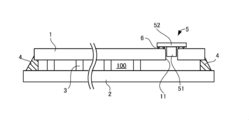
- the cover 5 has a small-diameter portion 51 inserted into the through hole 11 and a large-diameter portion 52 arranged on the surface of the first glass plate 1 and larger than the through hole 11. It can be one.
- the adhesive 6 is applied to the lower surface of the large diameter portion 52 and adhered to the surface of the first glass plate 1.
- the small-diameter portion 51 be smaller than the inner diameter of the through hole 11 or that a groove be formed on the outer peripheral surface thereof in order to secure an air flow path during depressurization.
- the adhesive 6 is also formed in a C-shape in plan view as described above to secure the air flow path.
- the small-diameter portion may be eliminated, and the cover 5 may be composed of only the large-diameter portion 52.
Landscapes
- Engineering & Computer Science (AREA)
- Chemical & Material Sciences (AREA)
- Civil Engineering (AREA)
- Structural Engineering (AREA)
- Life Sciences & Earth Sciences (AREA)
- General Chemical & Material Sciences (AREA)
- Geochemistry & Mineralogy (AREA)
- Materials Engineering (AREA)
- Organic Chemistry (AREA)
- Chemical Kinetics & Catalysis (AREA)
- Ceramic Engineering (AREA)
- Joining Of Glass To Other Materials (AREA)
- Securing Of Glass Panes Or The Like (AREA)
Abstract
本発明に係るガラスユニットは、貫通孔が形成された第1ガラス板と、前記第1ガラス板と所定間隔をおいて対向配置され、前記第1ガラス板との間に内部空間を形成する第2ガラス板と、前記第1ガラス板と第2ガラス板の周縁の隙間を封止する封止材と、前記貫通孔を塞ぐカバーと、前記カバーを前記第1ガラス板に固定する接着剤と、を備え、前記内部空間が真空状態となるように減圧されているか、あるいは前記内部空間に所定のガスが注入されており、前記第1ガラス板と前記カバーは前記接着剤により固定されている。
Description
本発明は、ガラスユニット及びその製造方法に関する。
近年、建築物等の窓ガラスには、複層ガラスで形成されたガラスユニットが多く採用されている。ガラスユニットは、2以上のガラス板の間に内部空間を形成したものであり、これによって、室内の断熱性を高めることを目的としている。このようなガラスユニットは複数の種類があり、断熱効果をさらに高めるため、内部空間を真空状態に減圧したガラスユニットが提案されている(例えば、特許文献1)。
ところで、特許文献1のガラスユニットでは、一方のガラス板に貫通孔を形成し、この貫通孔を通じて内部空間の減圧を行った後、貫通孔をガラス製のカバーによって閉鎖している。このとき、貫通孔の内周縁とカバーとの接触部分にレーザ光を照射し、これによってカバーを貫通孔に接合している。
しかしながら、この方法では、レーザ光の照射によりガラス製のカバーに局所的な熱が生じ、これによってカバーが割れるおそれがある。また、レーザ光を照射するため、装置が大型化するという問題もある。
本発明は、この問題を解決するためになされたのであり、カバーの割れを防止しつつ、簡易に製造することができる、ガラスユニット及びその製造方法を提供することを目的とする。
項1.貫通孔が形成された第1ガラス板と、
前記第1ガラス板と所定間隔をおいて対向配置され、前記第1ガラス板との間に内部空間を形成する第2ガラス板と、
前記第1ガラス板と第2ガラス板の周縁の隙間を封止する封止材と、
前記貫通孔を塞ぐカバーと、
前記カバーを前記第1ガラス板に固定する接着剤と、
を備え、
前記内部空間が真空状態となるように減圧されているか、あるいは前記内部空間に所定のガスが注入されており、
前記第1ガラス板と前記カバーは前記接着剤により固定されている、ガラスユニット。
前記第1ガラス板と所定間隔をおいて対向配置され、前記第1ガラス板との間に内部空間を形成する第2ガラス板と、
前記第1ガラス板と第2ガラス板の周縁の隙間を封止する封止材と、
前記貫通孔を塞ぐカバーと、
前記カバーを前記第1ガラス板に固定する接着剤と、
を備え、
前記内部空間が真空状態となるように減圧されているか、あるいは前記内部空間に所定のガスが注入されており、
前記第1ガラス板と前記カバーは前記接着剤により固定されている、ガラスユニット。
項2.前記貫通孔は、軸方向に連続する小径部と大径部とを有し、
前記小径部が前記内部空間側に配置され、
前記大径部と前記小径部との間の段に、前記接着剤を介して前記カバーが固定されている、項1に記載のガラスユニット。
前記小径部が前記内部空間側に配置され、
前記大径部と前記小径部との間の段に、前記接着剤を介して前記カバーが固定されている、項1に記載のガラスユニット。
項3.前記カバーは、前記大径部に収容され、
前記カバーと前記第1ガラス板の表面とが略同一面上にある、項2に記載のガラスユニット。
前記カバーと前記第1ガラス板の表面とが略同一面上にある、項2に記載のガラスユニット。
項4.前記カバーは、前記大径部に収容され、
前記カバーの表面は、前記第1ガラス板の表面より内側に位置している、項2のガラスユニット。
前記カバーの表面は、前記第1ガラス板の表面より内側に位置している、項2のガラスユニット。
項5.前記大径部の内径は、5mm以上15mm以下である、項2から4のいずれかに記載のガラスユニット。
項6.小径部と大径部の径の差が、3~20mmである項2から5のいずれかに記載のガラスユニット。
項7.前記大径部の深さと前記カバーの厚みとの差が、0.4mm以上0.7mm以下である、項2から6のいずれかに記載のガラスユニット。
項8.前記接着剤は、低融点ガラスを含有している、項1から8のいずれかに記載のガラスユニット。
項9.前記第1ガラス板の熱膨張率と前記接着剤の熱膨張率との差が、20×10-7/℃以下である、項1から8のいずれかに記載のガラスユニット。
項10.前記カバーは、ガラスにより形成されており、
前記カバーと前記第1ガラス板の熱膨張率は同一である、項1から9のいずれかに記載のガラスユニット。
前記カバーと前記第1ガラス板の熱膨張率は同一である、項1から9のいずれかに記載のガラスユニット。
項11.前記第1ガラス板に積層される中間膜及び第3ガラス板をさらに備え、
前記第1ガラス板、前記中間膜、及び前記第3ガラス板により合わせガラスが構成されている、項1から10のいずれかに記載のガラスユニット。
前記第1ガラス板、前記中間膜、及び前記第3ガラス板により合わせガラスが構成されている、項1から10のいずれかに記載のガラスユニット。
項12.前記接着剤は、ビスマス系の低融点ガラスを含有する、項1から8のいずれかに記載のガラスユニット。
項13.前記接着剤は、非結晶性である、項10に記載のガラスユニット。
項14.前記接着剤は、結晶性である、項10に記載のガラスユニット。
項15.前記封止材は、非結晶性の低融点ガラスにより形成されている、項12に記載のガラスユニット。
項16.前記封止材及び接着剤は、金属ハンダにより形成されている、項12に記載のガラスユニット。
項17.前記第1ガラス板及び前記第2ガラス板の少なくとも一方は、強化ガラスにより形成されている、項11から14のいずれかに記載のガラスユニット。
項18.前記第2ガラス板が強化ガラスにより形成されている、項17に記載のガラスユニット。
項19.前記強化ガラスは化学強化ガラスである項17または18に記載のガラスユニット。
項20.前記第1ガラス板及び第2ガラス板の周縁に取り付けられる、周縁部材であって、前記第1ガラス板に接する第1部位と、前記第2ガラス板に接する第2部位と、前記第1部位及び第2部位を連結する連結部とを有する断面U状に形成された周縁部材をさらに備え、
前記第1部位は、前記カバーを覆うように配置されている、項1から19のいずれかに記載のガラスユニット。
前記第1部位は、前記カバーを覆うように配置されている、項1から19のいずれかに記載のガラスユニット。
項21.前記第1ガラス板及び第2ガラス板の周縁に取り付けられる、周縁部材であって、前記第1ガラス板に接する第1部位と、前記第2ガラス板に接する第2部位と、前記第1部位及び第2部位を連結する連結部とを有する断面U状に形成された周縁部材をさらに備え、
前記カバーは、前記第1部位に覆われない位置に配置されている、項1から19のいずれかに記載のガラスユニット。
前記カバーは、前記第1部位に覆われない位置に配置されている、項1から19のいずれかに記載のガラスユニット。
項22.軸方向に連続する小径部と大径部とを有する貫通孔が形成された第1ガラス板を準備するステップと、
前記第1ガラス板の小径部側と対向するように、当該第1ガラス板と所定間隔をおいて、前記第2ガラス板を配置するステップと、
前記第1ガラス板及び第2ガラス板の周縁の隙間に封止用材料を配置するステップと、
前記大径部と小径部の間の段に、接着剤が配置されるようにして、当該接着剤を介して前記貫通孔を塞ぐようにカバーを配置するステップであって、前記貫通孔と前記接着剤及びカバーとの間に通気用の通路を形成するステップと、
前記カバーを押圧する錘を配置するステップと、
前記封止用材料を加熱後、冷却することで、当該封止用材料を固化し、前記周縁の隙間を封止する封止材を形成するステップと、
前記通気用の通路から、前記第1ガラス板と第2ガラス板との間の内部空間の減圧を行うステップと、
前記接着剤を加熱することで軟化させ、前記カバーによって前記貫通孔を密閉するステップと、
を備えている、ガラスユニットの製造方法。
項23.前記内部空間の減圧を行うステップは、前記封止用材料の冷却の過程において開始する、項22に記載のガラスユニットの製造方法。
項24.前記カバーは、前記大径部に収容され、
前記軟化した接着剤を冷却後に、前記カバーの表面を、前記第1ガラス板の表面と略同一面となる位置、または前記第1ガラス板の表面よりも窪んだ位置に、配置する、項22または23に記載のガラスユニットの製造方法。
前記軟化した接着剤を冷却後に、前記カバーの表面を、前記第1ガラス板の表面と略同一面となる位置、または前記第1ガラス板の表面よりも窪んだ位置に、配置する、項22または23に記載のガラスユニットの製造方法。
項25.前記錘を配置するステップに先立って、前記カバーを覆う保護プレートを配置するステップをさらに備え、
前記錘は、前記保護プレートを介して前記カバーが外部から視認可能なように、前記保護プレートを介して前記カバーを押圧する、項22から24のいずれかに記載のガラスユニットの製造方法。
前記錘は、前記保護プレートを介して前記カバーが外部から視認可能なように、前記保護プレートを介して前記カバーを押圧する、項22から24のいずれかに記載のガラスユニットの製造方法。
項26.前記保護プレートは、石英ガラスである、項25に記載のガラスユニットの製造方法。
項27.前記接着剤は、加熱前に前記段に、少なくとも一つの隙間を有する不連続な形状で、配置される、項22から26のいずれかに記載のガラスユニットの製造方法。
項28.前記接着剤は、ビスマス系のハンダである、項22から27のいずれかに記載のガラスユニットの製造方法。
項29.前記接着剤を前記カバーに取り付けた後、当該カバーを前記第1ガラス板に配置する、項22から28のいずれかに記載のガラスユニットの製造方法。
項30.前記接着剤は仮焼成により前記カバーに取り付けられる、項29に記載のガラスユニットの製造方法。
項31.前記接着剤の厚みは0.2mm以下であり、
印刷により前記カバーに取り付けられる、項22から30のいずれかにに記載のガラスユニットの製造方法。
印刷により前記カバーに取り付けられる、項22から30のいずれかにに記載のガラスユニットの製造方法。
本発明によれば、カバーの割れを防止しつつ、簡易に製造することができる。
<1.ガラスユニットの概要>
以下、本発明に係るガラスユニットの一実施形態について、図面を参照しつつ説明する。図1は本実施形態に係るガラスユニットの平面図、図2は図1の断面図である。図1及び図2に示すように、本実施形態に係るガラスユニットは、矩形状の2つのガラス板、つまり第1ガラス板1及び第2ガラス板2を有している。本実施形態においては、図2中の下側に示される第2ガラス板2が、第1ガラス板1よりもやや大きく形成されている。両ガラス板1,2の間には、複数のスペーサ3が配置され、これらスペーサ3によって、両ガラス板1,2の間に所定間隔の隙間が形成される。また、両ガラス板1,2の周縁の隙間は、封止材4によって封止されており、これによって、両ガラス板1,2の間には、密閉された内部空間100が形成される。さらに、第1ガラス板1には貫通孔11が形成されており、この貫通孔11を塞ぐ板状のカバー5が設けられている。このカバー5は、接着剤6を介して第1ガラス板1に固定されている。以下、各部材について説明する。
以下、本発明に係るガラスユニットの一実施形態について、図面を参照しつつ説明する。図1は本実施形態に係るガラスユニットの平面図、図2は図1の断面図である。図1及び図2に示すように、本実施形態に係るガラスユニットは、矩形状の2つのガラス板、つまり第1ガラス板1及び第2ガラス板2を有している。本実施形態においては、図2中の下側に示される第2ガラス板2が、第1ガラス板1よりもやや大きく形成されている。両ガラス板1,2の間には、複数のスペーサ3が配置され、これらスペーサ3によって、両ガラス板1,2の間に所定間隔の隙間が形成される。また、両ガラス板1,2の周縁の隙間は、封止材4によって封止されており、これによって、両ガラス板1,2の間には、密閉された内部空間100が形成される。さらに、第1ガラス板1には貫通孔11が形成されており、この貫通孔11を塞ぐ板状のカバー5が設けられている。このカバー5は、接着剤6を介して第1ガラス板1に固定されている。以下、各部材について説明する。
<2.第1ガラス板及び第2ガラス板>
第1ガラス板1を構成する材料は、特には限定されず、公知のガラス板を用いることができる。用途に応じて、例えば、型板ガラス、表面処理により光拡散機能を備えたすりガラス、網入りガラス、線入ガラス板、強化ガラス、倍強化ガラス、低反射ガラス、高透過ガラス板、セラミックガラス板、熱線や紫外線吸収機能を備えた特殊ガラス、又は、これらの組み合わせなど種々のガラス板を用いることができる。第1ガラス板1の厚みは、特には限定されないが、例えば、0.3~15mmであることが好ましく、0.5~8mmであることがさらに好ましい。
第1ガラス板1を構成する材料は、特には限定されず、公知のガラス板を用いることができる。用途に応じて、例えば、型板ガラス、表面処理により光拡散機能を備えたすりガラス、網入りガラス、線入ガラス板、強化ガラス、倍強化ガラス、低反射ガラス、高透過ガラス板、セラミックガラス板、熱線や紫外線吸収機能を備えた特殊ガラス、又は、これらの組み合わせなど種々のガラス板を用いることができる。第1ガラス板1の厚みは、特には限定されないが、例えば、0.3~15mmであることが好ましく、0.5~8mmであることがさらに好ましい。
第1ガラス板1の端部には、上述した貫通孔11が形成されている。この貫通孔11は、内部空間100側に配置される小径部111と、この小径部111と連続し外部に開放する大径部112とで構成されている。小径部111及び大径部112は、同軸の円筒状に形成されており、大径部112の内径が小径部211よりも大きくなっている。そのため、大径部112と小径部111の間には、外部を向く環状の段113が形成されている。
小径部111の内径は、例えば、1.0~3.0mmとすることができる。一方、大径部112の内径は、小径部111よりも大きく、5~15mmとすることができる。5mm以上とすることで、それに併せて小径部111を確保できるため、後述するように、内部空間100を真空状態にするときの空気の排出を効率的に行うことができる。また、後述するように、接着剤6を載せる段113のスペースを確保することができ、これによって接着剤6が溶融前に小径部111を塞ぐのを防止することができる。一方、15mm以内とすることで、貫通孔11を目立たなくすることができる。
また、大径部112と小径部111の径の差は、例えば、3~20mmとすることができる。径の差を3mm以上とすることで、後述するように、接着剤6を配置するスペースを適切に確保することができる。また、径の差が大きすぎると見栄えが悪くなるため、20mmを上限とすることが好ましい。
また、大径部112の深さ、つまり軸方向の長さは、例えば、0.5~1.5mmとすることができる。
第2ガラス板2は、第1ガラス板1と同じ材料で形成することができる。上述したように、第2ガラス板2は、第1ガラス板1よりもやや大きく、その周縁において、第1ガラス板1からはみ出した部分に、上述した封止材4が配置され、この封止材4によって、両ガラス板1,2の周縁の隙間が封止される。
また、各ガラス板1,2は、化学強化、風冷強化などの強化を施したガラス板であってもよい。特に、第2ガラス板2には、貫通孔が形成されていないため、後述する封止材や接着剤の加熱工程において強化の程度が低下するのを防止することができるため、強化を施すことが好ましい。風冷強化は、コストの観点から化学強化よりも有利であるものの、後述する封止材4や接着剤6の加熱工程で強化の程度が低下するおそれがある。これに対して、化学強化は,加熱工程においても、強化の程度が低下するのを抑制することができる。
なお、両ガラス板1,2の間に配置される複数のスペーサ3は、両ガラス板1,2の間の距離を一定に保つためのものであり、透明または半透明の公知のものを用いることができる。両ガラス板1,2の距離、つまり内部空間100の厚みは例えば、0.1~2.0mmとすることができる。
<3.カバー>
カバー5は、円板状に形成されており、その外径は、第1ガラス板1の貫通孔11の大径部112のよりも小さく、小径部111よりも大きくなっている。したがって、カバー5は、大径部112と小径部111との間の段113に配置されるようになっている。後述するように、減圧工程においては、カバー5と貫通孔11の間から空気を吸引するため、カバー5の外周面と大径部112の内周面との間には、隙間が必要である。そのため、カバー5は、大径部112の内径よりも0.2~1.5mmmm小さい外径とすることが好ましい。
カバー5は、円板状に形成されており、その外径は、第1ガラス板1の貫通孔11の大径部112のよりも小さく、小径部111よりも大きくなっている。したがって、カバー5は、大径部112と小径部111との間の段113に配置されるようになっている。後述するように、減圧工程においては、カバー5と貫通孔11の間から空気を吸引するため、カバー5の外周面と大径部112の内周面との間には、隙間が必要である。そのため、カバー5は、大径部112の内径よりも0.2~1.5mmmm小さい外径とすることが好ましい。
また、カバー5の厚みは、大径部112の深さよりも小さくされており、例えば、大径部112の深さとカバー5の厚みとの差が0.4~0.7mmであることが好ましい。後述するように、カバー5の表面は、第1ガラス板1の表面と概ね同一平面上に配置されるため、大径部112の深さとカバー5の厚みとの差が、上述した接着剤6の厚みとなる。したがって、例えば、この差が0.4mmよりも小さいと、接着剤6の厚みが小さくなるため、接着強度が低下するおそれがある。一方、この差が0.7mmより大きいと、接着剤6の厚みが大きくなるが、そのようにすると、後述するように接着剤6を溶融させるための熱が接着剤6に均一に伝達されず、接着強度が低下するおそれがある。また、カバー5の厚み、あるいは第1ガラス板1の厚みが薄くなり、割れが生じる可能性がある。
カバー5を構成する材料は、非通気性で、接着剤6及び封止材4を溶融する際の加熱温度よりも高い融点を有していれば、特には限定されないが、第1ガラス板1と同じ熱膨張率を有する材料で形成されていることが好ましく、特に、第1ガラス板1と同じ材料であることが好ましい。これにより、カバー5と接着剤6との熱膨張の差、及び第1ガラス板1と接着剤6との熱膨張の差を同じにすることができ、後述する製造工程において、第1ガラス板1やカバー5が割れるのを防止することができる。
<4.接着剤>
接着剤6は、カバー5を第1ガラス板1に接着できるのであれば、特には限定されないが、例えば、低融点ガラス、金属半田を含有したものを用いることができる。低融点ガラスは、例えば、鉛系、リン酸スズ系、ビスマス系、またはバナジウム系を採用することができる。低融点ガラスには、添加剤としてフィラーなどを含有することができる。また、これらは結晶性または非結晶性のいずれであってもよい。非結晶性の低融点ガラスは、後述するように減圧工程において発泡するが、流動性がよいため、カバー5を固定しやすい。一方、結晶性の低融点ガラスは、減圧工程において発泡しがたいため、封止性能が高いが、流動性が低いおそれがある。
接着剤6は、カバー5を第1ガラス板1に接着できるのであれば、特には限定されないが、例えば、低融点ガラス、金属半田を含有したものを用いることができる。低融点ガラスは、例えば、鉛系、リン酸スズ系、ビスマス系、またはバナジウム系を採用することができる。低融点ガラスには、添加剤としてフィラーなどを含有することができる。また、これらは結晶性または非結晶性のいずれであってもよい。非結晶性の低融点ガラスは、後述するように減圧工程において発泡するが、流動性がよいため、カバー5を固定しやすい。一方、結晶性の低融点ガラスは、減圧工程において発泡しがたいため、封止性能が高いが、流動性が低いおそれがある。
なお、非結晶性のバナジウム系の低融点ガラスは、融点が低いため、扱いやすいが、高温下で使用すると、一部が結晶化し、熱膨張率が増大するため、かえって扱いにくくなるおそれがある。一方、非結晶性のビスマス系の低融点ガラスは、融点はバナジウム系の低融点ガラスより高いが、高温下でも結晶化する可能性が低いため、扱いやすいという利点がある。
ここでいう低融点とは、例えば、500℃以下の融点をいう。接着剤6の融点が500℃を超えると、後述するヒーター92での加熱時間が長くなり生産性が低下するおそれがある。また、融点が低すぎると、後述するように、封止材4を溶融するときに接着剤6が溶融してしまい、貫通孔11が塞がれてしまう。そのため、封止材4の融点よりも、例えば、10~50℃高い融点を有することが好ましい。
また、接着剤6は後述するように、溶融した後、冷却して固化するが、固化したときの接着剤6の収縮により第1ガラス板1が割れるのを防止するため、例えば、室温から300℃まで温度を上昇させたときに、第1ガラス板1の熱膨張率と接着剤6の熱膨張率との差が、20×10-7mm/℃以下であることが好ましい。なお、上記のように接着剤6にガラスが含有されていると、接着対象となる第1ガラス板1と同質になるため、熱膨張率の差を特に小さくすることができる。これにより、例えば、接着剤6を加熱して固定する場合には、第1ガラス板1との熱膨張率の差が小さいため、割れを抑制することができる。
接着剤6の厚みは、最終製品となったときに、大径部112の深さとカバー5の厚みとの差となるようにしておく。後述するように、接着剤6は、加熱して溶融し、その後、冷却して固化させる。そのため、接着剤6の加熱前の厚みは、加熱後よりも大きくすることができる。また、接着剤6が加熱され溶融するときに、例えば、空気が進入することで接着剤6が膨張する場合もある。このような場合は、接着剤6の加熱前の厚みは、加熱後よりも小さくすることができる。
また、接着剤6は、貫通孔11の段113に直接配置してもよいが、予めカバー5に取り付け、そのカバー5を貫通孔11に取り付けてもよい。この場合、接着剤6は、仮焼成によりカバー5に固定することができる。例えば、接着剤6として、ビスマス系の低融点ガラスを用いる場合には、420~460℃程度で、仮焼成することができる。あるいは、インクジェットなどの印刷によってカバー5に取り付けることもできる。印刷による場合には、接着剤6の厚みは、例えば、0.2mm以下とすることができる。
接着剤6の形状は、貫通孔11の段113に配置されるような位置、形状に形成されていればよいが、特に環状に形成することが好ましい。但し、後述するように、減圧工程での空気の通路を確保するため、不連続な環状、例えば、図3に示すように、C字状(a)、複数の円弧を間隔をおいて組み合わせたもの(b)、放射状に配置したもの(c)など、少なくとも一つの隙間を有するように形成されることが好ましい。
<5.封止材>
封止材4は、接着剤6と同様の材料を用いることができる。例えば、封止材4として、非結晶性の低融点ガラスを用いると、流動性が高いため、両ガラス板1,2の隙間に封止材4を流し込みやすく、好ましい。この場合、封止性能を向上するため、封止材4が、第1ガラス板1の端面から、例えば、2~7mm入り込むことが好ましい。上限は7mm入り込む。
封止材4は、接着剤6と同様の材料を用いることができる。例えば、封止材4として、非結晶性の低融点ガラスを用いると、流動性が高いため、両ガラス板1,2の隙間に封止材4を流し込みやすく、好ましい。この場合、封止性能を向上するため、封止材4が、第1ガラス板1の端面から、例えば、2~7mm入り込むことが好ましい。上限は7mm入り込む。
上記のように封止材4としては、低融点ガラスまたは金属半田を用いることができるが、後述する製造工程を採用する場合には、接着剤6の融点が、封止材4の融点よりも高いことが必要である。例えば、接着剤6及び封止材4がともに、同種の低融点ガラスである場合には、低融点ガラスの量や添加物であるフィラーなどの量を調整することで、接着剤6の融点を封止材4の融点よりも高くすることができる。
この観点から、例えば、封止材4として低融点ガラスを用いる場合には、接着剤6として、低融点ガラスよりも融点の低い金属半田を用いることはできない。その一方で、封止材4及び接着剤6として、ともに金属半田を用いることもできるが、上述したように、接着剤6の融点が高くなるように調整しておくことが必要である。
<6.ガラスユニットの製造方法>
次に、ガラスユニットの製造方法について説明する。まず、図4に示すような構造を組み立てる。すなわち、上記のような貫通孔11が形成された第1ガラス板1と、第2ガラス板2とを準備する。次に、第2ガラス板2上に複数のスペーサ3を配置した後、その上に第1ガラス板1を配置する。
次に、ガラスユニットの製造方法について説明する。まず、図4に示すような構造を組み立てる。すなわち、上記のような貫通孔11が形成された第1ガラス板1と、第2ガラス板2とを準備する。次に、第2ガラス板2上に複数のスペーサ3を配置した後、その上に第1ガラス板1を配置する。
また、両ガラス板1,2の周縁の隙間を塞ぐように、第2ガラス板2の周縁に封止用材料40を配置する。これは、溶融、固化する前の封止材4である。
また、上述したように、カバー5の一方の面にC字状の接着剤6を仮焼成等により取り付けておく。そして、このカバー5を第1ガラス板1の貫通孔11に取り付ける。このとき、接着剤6が、貫通孔11の段113に配置されるようにする。続いて、カバー5の上に、貫通孔11の大径部112よりも大きい円板状の保護プレート7を配置し、さらにに、この保護プレート7上に、錘8を配置する。これにより、保護プレート7を介して、錘8によってカバー5が段113に押圧される。
このとき、接着剤6は仮焼成され固化しているため、押し潰されることはなく、接着剤6によって、カバー5と段113の間には隙間が形成されている。また、保護プレート7の下面には、図5に示すように、十字状の溝71が形成されている。そのため、ガラスユニットの内部空間100と外部とは、貫通孔11の小径部111、接着剤6の不連続部分、大径部112とカバー5との隙間、及び保護プレート7の溝71を介して、空気が流通するようになっている。
保護プレート7は、後述するように、熱を通す必要があるため、赤外線の吸収量が少なく、加熱したときの膨張率が低く材料で形成することが好ましい。例えば、石英ガラス、あるいはカバー5やガラス板1,2と同じ材料を用いることができる。なお、保護プレート7は、後述するヒータ-92による輻射熱で接着剤6を加熱することを阻害しない材質であればよく、透明のほか、不透明であってもよい。
錘8は、カバー5を塞がないように、保護プレート7の周縁部を押圧するような形状とすることができ、例えば、ドーナツ型に形成したものとすることができる。但し、錘8は、上述した空気の流路を確保するような形状とする必要がある。すなわち、保護プレート7の溝71が外部に開放されるような構造にする必要がある。
このように、保護プレート7と錘8を配置した後、これらを覆うようにカップ状の閉鎖部材9を第1ガラス板1の上面に取り付ける。これにより、貫通孔11を含む閉鎖部材9で囲まれた空間が密閉される。また、この閉鎖部材9の上部には、開口91が形成されており、この開口91は真空ポンプ(図示省略)に接続され、内部空間の減圧を行うようになっている。さらに、閉鎖部材9の内部において、保護プレート7の上方には、タングステン等のヒーター92が設けられており、このヒーター92によって、接着剤6が加熱されるようになっている。
こうして、閉鎖部材9が取り付けられた後、これらを加熱炉(図示省略)に配置し、加熱を行う。まず、封止用材料40の融点以上に加熱を行い、封止用材料40を溶融する。溶融した封止用材料40は、両ガラス板1,2の周縁の隙間に入り込む。封止用材料40として、例えば、ビスマス系低融点ガラスを用いる場合には、470℃程度に加熱する。その後、加熱炉の温度を、例えば、380~460℃程度まで低下し、封止用材料40を固化していく。このときの加熱温度は、接着剤6の融点よりも低いため、接着剤6は溶融しない。したがって、上述した空気の流路は確保されている。なお、封止用材料40を加熱する手段は、特には限定されず、輻射加熱、レーザによる加熱、誘導加熱等を採用することができる。特に、封止用材料40が金属である場合には、誘導加熱を採用することができる。
続いて、真空ポンプを駆動し、減圧を行う。すなわち、上述した空気の流路を通じて、内部空間100の減圧が行われる。内部空間100の圧力が、例えば、0.1Pa以下となれば、真空状態と見なすことができる。
この減圧工程によって、両ガラス板1,2が互いに近接する方向に力が作用し、封止用材料40も同時に押しつぶされる。これにより、封止用材料40内部の空隙を消失させることができるため、封止材4を介した気体のリークを防止することができる。したがって、減圧は、封止用材料40が完全に固化する前の温度で開始することが好ましく、これを考慮して上述した封止用材料を固化するための温度(上記の例では380~460℃)を決定することができる。例えば、封止用材料40の融点よりも50~150℃低い温度になったときに、減圧を行うことができる。なお、封止用材料40が、例えば、金属ハンダを用いる場合には、上述の380~460℃によらず封止用材料40を固化させていくことができる。
これに続いて、ヒーター92を駆動し、接着剤6を加熱する。接着剤6が、例えば、ビスマス系の低融点ガラスにより形成されている場合には、ヒーター92により、接着剤6の温度が500℃程度になるようにする。これにより、接着剤6が溶融し、錘8による押圧も手伝って、接着剤6が押し潰されていく。その結果、C字状の接着剤6が環状に変形し、カバー5と接着剤6により、貫通孔11の小径部111が気密に密閉される。こうして、内部空間100の真空状態が維持される。その後、ヒーター92の駆動を停止し、全体を徐冷すると、封止用材料40が完全に固化し、封止材4として両ガラス板1,2の周縁の隙間を封止する。以上の工程により、ガラスユニットが完成する。なお、接着剤6が加熱できるのであれば、上述したヒーター92以外の装置を用いてもよい。
<7.特徴>
以上のように、本実施形態によれば、以下の効果を得ることができる。
(1)カバー5を接着剤6により第1ガラス板1に固定しているため、従来例のようにカバーに直接レーザ光を照射するのに比べ、第1ガラス板1あるいはカバー5の温度分布の差が生じにくく、割れを防止することができる。また、レーザ光を照射するための大型の装置が不要であり、内部空間100の減圧と貫通孔11の閉鎖を簡易に行うことができる。
以上のように、本実施形態によれば、以下の効果を得ることができる。
(1)カバー5を接着剤6により第1ガラス板1に固定しているため、従来例のようにカバーに直接レーザ光を照射するのに比べ、第1ガラス板1あるいはカバー5の温度分布の差が生じにくく、割れを防止することができる。また、レーザ光を照射するための大型の装置が不要であり、内部空間100の減圧と貫通孔11の閉鎖を簡易に行うことができる。
(2)接着剤6として非結晶性の低融点ガラスを用いた場合、流動性の制御など取り扱いやすく、カバー5によって貫通孔11をしっかりと塞ぐことができる。その一方で、非結晶性の低融点ガラスは、減圧時に発泡するおそれがあるが、接着剤6は、カバー5と段113との間に挟まれているため、発泡が抑制される。そのため、接着性能の低下や、接着剤6からの気体のリークを防止することができる。
(3)上記製造工程において、カバー5全体を覆う保護プレート7を用いると、ヒーター92による加熱時に、カバー5内の温度分布を概ね均一にすることができる。例えば、保護プレート7を用いることなく、錘8で直接カバー5を押圧すると、カバー5において、錘8が接している部分と接していない部分とで温度の差が生じ、カバー5が割れるおそれがあるが、保護プレート7を用いることで、そのような割れを防止することができる。但し、保護プレート7は必須ではなく、温度分布を考慮し、錘8だけでカバーを押圧することもできる。
<8.変形例>
以上、本発明の一実施形態について説明したが、本発明は上記実施形態に限定されるものではなく、その趣旨を逸脱しない限りにおいて、種々の変更が可能である。なお、以下の変形例は、適宜、組み合わせ可能である。
以上、本発明の一実施形態について説明したが、本発明は上記実施形態に限定されるものではなく、その趣旨を逸脱しない限りにおいて、種々の変更が可能である。なお、以下の変形例は、適宜、組み合わせ可能である。
<8-1>
上記実施形態では、カバー5と第1ガラス板1の表面とが概ね同一平面上に位置するように、調整しているが、これに限定されない。すなわち、両者が同一平面上にあれば好ましいが、カバー5が第1ガラス板1の表面からやや突出したり、あるいは貫通孔11内にやや窪むように配置されてもよい。例えば、カバー5と第1ガラス板1の表面との差が、1.0mm以内とすることができる。特に、カバー5が第1ガラス板1の表面から内側に位置していると、後述する図7に示す周縁部材500を取り付けるときの邪魔にならない。
上記実施形態では、カバー5と第1ガラス板1の表面とが概ね同一平面上に位置するように、調整しているが、これに限定されない。すなわち、両者が同一平面上にあれば好ましいが、カバー5が第1ガラス板1の表面からやや突出したり、あるいは貫通孔11内にやや窪むように配置されてもよい。例えば、カバー5と第1ガラス板1の表面との差が、1.0mm以内とすることができる。特に、カバー5が第1ガラス板1の表面から内側に位置していると、後述する図7に示す周縁部材500を取り付けるときの邪魔にならない。
この観点から、例えば、図6に示すように、カバー5の厚みが薄ければ、カバー5を第1ガラス板1の表面に配置することもできる。この場合、カバー5の厚みは、0.3~0.6mmであることが好ましい。また、接着剤は、上記実施形態と同様に、段113に配置されるが、上記工程を採用する場合、空気の流路を確保するため、加熱前の接着剤6の厚みは、大径部112の深さよりも大きいことが必要である。
<8-2>
貫通孔11の形状は特には限定されず、少なくとも上記のような段113が形成されるように小径部111と大径部112とを有していればよく、平面形状は円形のほか、多角形状などでもよい。また、カバー5を大径部112に収容する態様の場合は、大径部112に収容できる形状であればよいが、図6に示すように、第1ガラス板1の表面に配置する場合には、特には限定されない。
貫通孔11の形状は特には限定されず、少なくとも上記のような段113が形成されるように小径部111と大径部112とを有していればよく、平面形状は円形のほか、多角形状などでもよい。また、カバー5を大径部112に収容する態様の場合は、大径部112に収容できる形状であればよいが、図6に示すように、第1ガラス板1の表面に配置する場合には、特には限定されない。
<8-3>
上記実施形態では、第2ガラス板2を第1ガラス板1よりも大きくしているが、同じ形状であってもよい。この場合、封止材4は、両ガラス板1,2の周縁の隙間に充填される。
上記実施形態では、第2ガラス板2を第1ガラス板1よりも大きくしているが、同じ形状であってもよい。この場合、封止材4は、両ガラス板1,2の周縁の隙間に充填される。
<8-4>
ガラスユニットの周縁には、グレージングチャネルのような周縁部を保護する周縁部材を取り付けることもできる。例えば、図7に示す周縁部材500は、第1ガラス板1の周縁部に当接する板状の第1部位501と、第2ガラス板2の周縁部に当接する板状の第2部位502と、これら第1部位501及び第2部位502を連結する板状の連結部位503を備えた断面U字状に形成されている。このような周縁部材500は、接着剤や両面テープなどで各ガラス板の表面あるいは端面に固定される。
ガラスユニットの周縁には、グレージングチャネルのような周縁部を保護する周縁部材を取り付けることもできる。例えば、図7に示す周縁部材500は、第1ガラス板1の周縁部に当接する板状の第1部位501と、第2ガラス板2の周縁部に当接する板状の第2部位502と、これら第1部位501及び第2部位502を連結する板状の連結部位503を備えた断面U字状に形成されている。このような周縁部材500は、接着剤や両面テープなどで各ガラス板の表面あるいは端面に固定される。
また、この周縁部材500の第1部位501は、図7に示すように、カバー5を塞ぐように配置することができる。これにより、カバー5が見えるのを防止することができる。あるいは、図8に示すように、カバー5を塞がないように配置することができる。これにより、例えば、周縁部材500の取付時に、第1部位501によりカバー5が傷ついたり、カバー5が外れたりするのを防止することができる。
<8-5>
上記のようにガラスユニットを製造した後、第1ガラス板1上に、中間膜、第3ガラス板をこの順で配置し、公知のオートクレーブによりこれらを固定することで、第1ガラス板1、中間膜、及び第3ガラス板による合わせガラスを形成することもできる。中間膜は、合わせガラスで用いられる公知の樹脂フィルムを用いることができ、第3ガラス板は、第1ガラス板1と同様のガラス板を用いることができる。
上記のようにガラスユニットを製造した後、第1ガラス板1上に、中間膜、第3ガラス板をこの順で配置し、公知のオートクレーブによりこれらを固定することで、第1ガラス板1、中間膜、及び第3ガラス板による合わせガラスを形成することもできる。中間膜は、合わせガラスで用いられる公知の樹脂フィルムを用いることができ、第3ガラス板は、第1ガラス板1と同様のガラス板を用いることができる。
上記のように、カバー5が第1ガラス板1の表面と略同一平面上にあれば、カバー5が邪魔にならず、中間膜60及び第3ガラス板70を積層することができる。よって、上記のように強化が施された第1ガラス板1を用いる以外に、合わせガラスを形成することで、本発明に係るガラスユニットを安全ガラスとすることができる。
<8-6>
第1ガラス板1及び第2ガラス板2の少なくとも一方に、公知のLow-E膜を積層することもできる。
第1ガラス板1及び第2ガラス板2の少なくとも一方に、公知のLow-E膜を積層することもできる。
<8-7>
両ガラス板1,2の間を所定間隔にする方法は種々の方法があり、上記のように両ガラス板1,2の間に複数のスペーサ3を設けるほか、両ガラス板1,2の周縁部のみにスペーサを設けることもできる。
両ガラス板1,2の間を所定間隔にする方法は種々の方法があり、上記のように両ガラス板1,2の間に複数のスペーサ3を設けるほか、両ガラス板1,2の周縁部のみにスペーサを設けることもできる。
<8-8>
上記実施形態では、両ガラス板1,2の間の内部空間を真空状態に減圧しているが、減圧に代えて、例えば、アルゴン、キセノンなどの不活性ガスを注入することもできる。この場合、内部空間100の厚みは5mm程度にすることが好ましい。また、不活性ガスを注入することで、スペーサ3が不要となる効果を奏する。なお、不活性ガスを注入した場合には、真空状態よりもやや遮熱性能が低下するが、実用には耐えうる遮熱性能は維持することができる。
上記実施形態では、両ガラス板1,2の間の内部空間を真空状態に減圧しているが、減圧に代えて、例えば、アルゴン、キセノンなどの不活性ガスを注入することもできる。この場合、内部空間100の厚みは5mm程度にすることが好ましい。また、不活性ガスを注入することで、スペーサ3が不要となる効果を奏する。なお、不活性ガスを注入した場合には、真空状態よりもやや遮熱性能が低下するが、実用には耐えうる遮熱性能は維持することができる。
<8-9>
上記実施形態では、大径部112と小径部111との間の段113に接着剤6を配置しているが、これに限定されるものではなく、例えば、カバー5の底面全体、カバー5の外周面などに接着剤を配置することもできる。
上記実施形態では、大径部112と小径部111との間の段113に接着剤6を配置しているが、これに限定されるものではなく、例えば、カバー5の底面全体、カバー5の外周面などに接着剤を配置することもできる。
<8-10>
本発明のガラスユニットは、遮熱性能が要求される建物の窓ガラスのほか、装置(例えば、冷蔵庫などの装置)の外面に装着されるカバーガラスとして用いることができる。また、第1ガラス板1及び第2ガラス板2のいずれを、装着される装置、建物などの外側を向くように配置してもよいが、貫通孔11が形成された第1ガラス板1は、第2ガラス板2と比べて強度が低いため、第2ガラス板2を外側に向けることが好ましい。
本発明のガラスユニットは、遮熱性能が要求される建物の窓ガラスのほか、装置(例えば、冷蔵庫などの装置)の外面に装着されるカバーガラスとして用いることができる。また、第1ガラス板1及び第2ガラス板2のいずれを、装着される装置、建物などの外側を向くように配置してもよいが、貫通孔11が形成された第1ガラス板1は、第2ガラス板2と比べて強度が低いため、第2ガラス板2を外側に向けることが好ましい。
<8-11>
上記実施形態では、貫通孔11を、軸方向に連続する大径部112及び小径部111により構成したが、径が一定の貫通孔であってもよい。この場合、図9に示すように、カバー5は、貫通孔11に挿入される小径部51と、第1ガラス板1の表面に配置され、貫通孔11よリも大きい大径部52とが一体となったものとすることができる。また、接着剤6は、大径部52の下面に塗布され、第1ガラス板1の表面に接着される。このとき、減圧時の空気の流路を確保するため、小径部51は、貫通孔11の内径よりも小さくしたり、あるいは外周面に溝を形成することが好ましい。また、接着剤6も上述したような平面視C字状に形成して空気の流路を確保することが好ましい。あるいは、小径部をなくし、大径部52だけでカバー5を構成してもよい。
上記実施形態では、貫通孔11を、軸方向に連続する大径部112及び小径部111により構成したが、径が一定の貫通孔であってもよい。この場合、図9に示すように、カバー5は、貫通孔11に挿入される小径部51と、第1ガラス板1の表面に配置され、貫通孔11よリも大きい大径部52とが一体となったものとすることができる。また、接着剤6は、大径部52の下面に塗布され、第1ガラス板1の表面に接着される。このとき、減圧時の空気の流路を確保するため、小径部51は、貫通孔11の内径よりも小さくしたり、あるいは外周面に溝を形成することが好ましい。また、接着剤6も上述したような平面視C字状に形成して空気の流路を確保することが好ましい。あるいは、小径部をなくし、大径部52だけでカバー5を構成してもよい。
1 第1ガラス板
11 貫通孔
111 小径部
112 大径部
113 段
2 第2ガラス板
4 封止材
5 カバー
6 接着剤
11 貫通孔
111 小径部
112 大径部
113 段
2 第2ガラス板
4 封止材
5 カバー
6 接着剤
Claims (31)
- 貫通孔が形成された第1ガラス板と、
前記第1ガラス板と所定間隔をおいて対向配置され、前記第1ガラス板との間に内部空間を形成する第2ガラス板と、
前記第1ガラス板と第2ガラス板の周縁の隙間を封止する封止材と、
前記貫通孔を塞ぐカバーと、
前記カバーを前記第1ガラス板に固定する接着剤と、
を備え、
前記内部空間が真空状態となるように減圧されているか、あるいは前記内部空間に所定のガスが注入されており、
前記第1ガラス板と前記カバーは前記接着剤により固定されている、ガラスユニット。 - 前記貫通孔は、軸方向に連続する小径部と大径部とを有し、
前記小径部が前記内部空間側に配置され、
前記大径部と前記小径部との間の段に、前記接着剤を介して前記カバーが固定されている、請求項1に記載のガラスユニット。 - 前記カバーは、前記大径部に収容され、
前記カバーと前記第1ガラス板の表面とが略同一面上にある、請求項2に記載のガラスユニット。 - 前記カバーは、前記大径部に収容され、
前記カバーの表面は、前記第1ガラス板の表面より内側に位置している、請求項2のガラスユニット。 - 前記大径部の内径は、5mm以上15mm以下である、請求項2から4のいずれかに記載のガラスユニット。
- 小径部と大径部の径の差が、3~20mmである請求項2から5のいずれかに記載のガラスユニット。
- 前記大径部の深さと前記カバーの厚みとの差が、0.4mm以上0.7mm以下である、請求項2から6のいずれかに記載のガラスユニット。
- 前記接着剤は、低融点ガラスを含有している、請求項1から7のいずれかに記載のガラスユニット。
- 前記第1ガラス板の熱膨張率と前記接着剤の熱膨張率との差が、20×10-7/℃以下である、請求項1から8のいずれかに記載のガラスユニット。
- 前記カバーは、ガラスにより形成されており、
前記カバーと前記第1ガラス板の熱膨張率は同一である、請求項1から9のいずれかに記載のガラスユニット。 - 前記第1ガラス板に積層される中間膜及び第3ガラス板をさらに備え、
前記第1ガラス板、前記中間膜、及び前記第3ガラス板により合わせガラスが構成されている、請求項1から10のいずれかに記載のガラスユニット。 - 前記接着剤は、ビスマス系の低融点ガラスを含有する、請求項1から8のいずれかに記載のガラスユニット。
- 前記接着剤は、非結晶性である、請求項10に記載のガラスユニット。
- 前記接着剤は、結晶性である、請求項10に記載のガラスユニット。
- 前記封止材は、非結晶性の低融点ガラスにより形成されている、請求項12に記載のガラスユニット。
- 前記封止材及び接着剤は、金属ハンダにより形成されている、請求項12に記載のガラスユニット。
- 前記第1ガラス板及び前記第2ガラス板の少なくとも一方は、強化ガラスにより形成されている、請求項11から14のいずれかに記載のガラスユニット。
- 前記第2ガラス板が強化ガラスにより形成されている、請求項17に記載のガラスユニット。
- 前記強化ガラスは化学強化ガラスである請求項17または18に記載のガラスユニット。
- 前記第1ガラス板及び第2ガラス板の周縁に取り付けられる、周縁部材であって、前記第1ガラス板に接する第1部位と、前記第2ガラス板に接する第2部位と、前記第1部位及び第2部位を連結する連結部とを有する断面U状に形成された周縁部材をさらに備え、
前記第1部位は、前記カバーを覆うように配置されている、請求項1から19のいずれかに記載のガラスユニット。 - 前記第1ガラス板及び第2ガラス板の周縁に取り付けられる、周縁部材であって、前記第1ガラス板に接する第1部位と、前記第2ガラス板に接する第2部位と、前記第1部位及び第2部位を連結する連結部とを有する断面U状に形成された周縁部材をさらに備え、
前記カバーは、前記第1部位に覆われない位置に配置されている、請求項1から19のいずれかに記載のガラスユニット。 - 軸方向に連続する小径部と大径部とを有する貫通孔が形成された第1ガラス板を準備するステップと、
前記第1ガラス板の小径部側と対向するように、当該第1ガラス板と所定間隔をおいて、前記第2ガラス板を配置するステップと、
前記第1ガラス板及び第2ガラス板の周縁の隙間に封止用材料を配置するステップと、
前記大径部と小径部の間の段に、接着剤が配置されるようにして、当該接着剤を介して前記貫通孔を塞ぐようにカバーを配置するステップであって、前記貫通孔と前記接着剤及びカバーとの間に通気用の通路を形成するステップと、
前記カバーを押圧する錘を配置するステップと、
前記封止用材料を加熱後、冷却することで、当該封止用材料を固化し、前記周縁の隙間を封止する封止材を形成するステップと、
前記通気用の通路から、前記第1ガラス板と第2ガラス板との間の内部空間の減圧を行うステップと、
前記接着剤を加熱することで軟化させ、前記カバーによって前記貫通孔を密閉するステップと、
を備えている、ガラスユニットの製造方法。 - 前記内部空間の減圧を行うステップは、前記封止用材料の冷却の過程において開始する、請求項22に記載のガラスユニットの製造方法。
- 前記カバーは、前記大径部に収容され、
前記軟化した接着剤を冷却後に、前記カバーの表面を、前記第1ガラス板の表面と略同一面となる位置、または前記第1ガラス板の表面よりも窪んだ位置に、配置する、請求項22または23に記載のガラスユニットの製造方法。 - 前記錘を配置するステップに先立って、前記カバーを覆う保護プレートを配置するステップをさらに備え、
前記錘は、前記保護プレートを介して前記カバーが外部から視認可能なように、前記保護プレートを介して前記カバーを押圧する、請求項22から24のいずれかに記載のガラスユニットの製造方法。 - 前記保護プレートは、石英ガラスである、請求項25に記載のガラスユニットの製造方法。
- 前記接着剤は、加熱前に前記段に、少なくとも一つの隙間を有する不連続な形状で、配置される、請求項22から26のいずれかに記載のガラスユニットの製造方法。
- 前記接着剤は、ビスマス系のハンダである、請求項22から27のいずれかに記載のガラスユニットの製造方法。
- 前記接着剤を前記カバーに取り付けた後、当該カバーを前記第1ガラス板に配置する、請求項22から28のいずれかに記載のガラスユニットの製造方法。
- 前記接着剤は仮焼成により前記カバーに取り付けられる、請求項29に記載のガラスユニットの製造方法。
- 前記接着剤の厚みは0.2mm以下であり、
印刷により前記カバーに取り付けられる、請求項22から30のいずれかに記載のガラスユニットの製造方法。
Priority Applications (3)
| Application Number | Priority Date | Filing Date | Title |
|---|---|---|---|
| EP19871286.1A EP3865464A4 (en) | 2018-10-12 | 2019-10-11 | Glass unit |
| US17/284,372 US20210388667A1 (en) | 2018-10-12 | 2019-10-11 | Glass unit |
| CN201980067280.9A CN112839914A (zh) | 2018-10-12 | 2019-10-11 | 玻璃单元 |
Applications Claiming Priority (2)
| Application Number | Priority Date | Filing Date | Title |
|---|---|---|---|
| JP2018193907A JP7479118B2 (ja) | 2018-10-12 | 2018-10-12 | ガラスユニットの製造方法 |
| JP2018-193907 | 2018-10-12 |
Publications (1)
| Publication Number | Publication Date |
|---|---|
| WO2020075833A1 true WO2020075833A1 (ja) | 2020-04-16 |
Family
ID=70163998
Family Applications (1)
| Application Number | Title | Priority Date | Filing Date |
|---|---|---|---|
| PCT/JP2019/040141 WO2020075833A1 (ja) | 2018-10-12 | 2019-10-11 | ガラスユニット |
Country Status (5)
| Country | Link |
|---|---|
| US (1) | US20210388667A1 (ja) |
| EP (1) | EP3865464A4 (ja) |
| JP (1) | JP7479118B2 (ja) |
| CN (1) | CN112839914A (ja) |
| WO (1) | WO2020075833A1 (ja) |
Citations (6)
| Publication number | Priority date | Publication date | Assignee | Title |
|---|---|---|---|---|
| JP2001064042A (ja) * | 1999-08-24 | 2001-03-13 | Central Glass Co Ltd | 低圧複層ガラスおよびその製造方法 |
| JP2003137612A (ja) * | 2001-10-25 | 2003-05-14 | Nippon Sheet Glass Co Ltd | ガラスパネルとその製法 |
| JP3096372U (ja) * | 2003-03-10 | 2003-09-12 | サンエス化学工業株式会社 | ガス封入防犯複層ガラス |
| JP2014088316A (ja) * | 2009-11-27 | 2014-05-15 | Luoyang Landglass Technology Co Ltd | 真空ガラス吸気孔の密封方法及び密封構造 |
| WO2016009948A1 (ja) * | 2014-07-18 | 2016-01-21 | 旭硝子株式会社 | 真空複層ガラス |
| JP2017141136A (ja) | 2016-02-12 | 2017-08-17 | パナソニックIpマネジメント株式会社 | ガラスパネルユニットの製造方法及びガラスパネルユニット |
Family Cites Families (8)
| Publication number | Priority date | Publication date | Assignee | Title |
|---|---|---|---|---|
| JP2002255594A (ja) * | 2001-02-23 | 2002-09-11 | Nippon Sheet Glass Co Ltd | ガラスパネルの製造方法 |
| JP2005320229A (ja) * | 2004-04-08 | 2005-11-17 | Nippon Sheet Glass Co Ltd | 減圧ガラスパネル及びその製造方法 |
| KR101322585B1 (ko) * | 2011-08-25 | 2013-10-28 | (주)엘지하우시스 | 진공유리 및 그 제조방법 |
| US10280680B2 (en) * | 2013-12-31 | 2019-05-07 | Guardian Glass, LLC | Vacuum insulating glass (VIG) unit with pump-out port sealed using metal solder seal, and/or method of making the same |
| GB2528634A (en) * | 2014-05-09 | 2016-02-03 | Pierce Developments Holdings Ltd | Glazing systems |
| US10882784B2 (en) * | 2015-09-29 | 2021-01-05 | Panasonic Intellectual Property Management Co., Ltd. | Glass panel unit manufacturing method and glass window manufacturing method |
| WO2018062071A1 (ja) * | 2016-09-30 | 2018-04-05 | パナソニックIpマネジメント株式会社 | ガラスパネルユニットの製造方法、およびガラス窓の製造方法 |
| CN107337358B (zh) * | 2017-01-26 | 2018-12-14 | 连玉琦 | 一种真空玻璃及其制备方法 |
-
2018
- 2018-10-12 JP JP2018193907A patent/JP7479118B2/ja active Active
-
2019
- 2019-10-11 CN CN201980067280.9A patent/CN112839914A/zh active Pending
- 2019-10-11 WO PCT/JP2019/040141 patent/WO2020075833A1/ja unknown
- 2019-10-11 EP EP19871286.1A patent/EP3865464A4/en active Pending
- 2019-10-11 US US17/284,372 patent/US20210388667A1/en active Pending
Patent Citations (6)
| Publication number | Priority date | Publication date | Assignee | Title |
|---|---|---|---|---|
| JP2001064042A (ja) * | 1999-08-24 | 2001-03-13 | Central Glass Co Ltd | 低圧複層ガラスおよびその製造方法 |
| JP2003137612A (ja) * | 2001-10-25 | 2003-05-14 | Nippon Sheet Glass Co Ltd | ガラスパネルとその製法 |
| JP3096372U (ja) * | 2003-03-10 | 2003-09-12 | サンエス化学工業株式会社 | ガス封入防犯複層ガラス |
| JP2014088316A (ja) * | 2009-11-27 | 2014-05-15 | Luoyang Landglass Technology Co Ltd | 真空ガラス吸気孔の密封方法及び密封構造 |
| WO2016009948A1 (ja) * | 2014-07-18 | 2016-01-21 | 旭硝子株式会社 | 真空複層ガラス |
| JP2017141136A (ja) | 2016-02-12 | 2017-08-17 | パナソニックIpマネジメント株式会社 | ガラスパネルユニットの製造方法及びガラスパネルユニット |
Non-Patent Citations (1)
| Title |
|---|
| See also references of EP3865464A4 |
Also Published As
| Publication number | Publication date |
|---|---|
| JP2020059640A (ja) | 2020-04-16 |
| EP3865464A4 (en) | 2022-06-29 |
| EP3865464A1 (en) | 2021-08-18 |
| US20210388667A1 (en) | 2021-12-16 |
| JP7479118B2 (ja) | 2024-05-08 |
| CN112839914A (zh) | 2021-05-25 |
Similar Documents
| Publication | Publication Date | Title |
|---|---|---|
| US6701749B2 (en) | Vacuum IG window unit with edge seal at least partially diffused at temper and completed via microwave curing, and corresponding method of making the same | |
| EP2847409B1 (en) | Vacuum insulated glass window unit including pump-out tube protection ring and cap and method for making same | |
| US6558494B1 (en) | Vacuum IG window unit with edge seal at least partially diffused at temper and completed via microwave curing, and corresponding method of making the same | |
| JP2003306354A (ja) | ガラスパネルの製造方法とその方法で製造されたガラスパネル | |
| JP6507461B2 (ja) | ガラスパネルユニットの製造方法およびガラス窓の製造方法 | |
| JP2004323317A (ja) | ガラスパネルの中間膜圧着方法 | |
| JP6425174B2 (ja) | 真空ガラスパネルの製造方法 | |
| EP2432636B1 (en) | Laminated glazing | |
| WO2020075833A1 (ja) | ガラスユニット | |
| KR101322585B1 (ko) | 진공유리 및 그 제조방법 | |
| US20210270084A1 (en) | Method for manufacturing glass panel unit | |
| WO2020209371A1 (ja) | ガラスユニット | |
| US20210348439A1 (en) | Pump out tube preform | |
| US11268317B2 (en) | Method for manufacturing glass panel unit | |
| JP7383382B2 (ja) | ガラスユニット | |
| EP3583080B1 (en) | Top frit heat treatment | |
| JP6425175B2 (ja) | 真空ガラスパネル及びその製造方法 | |
| KR20190024313A (ko) | 진공 유리 패널 및 그 제조 방법 | |
| US20220259916A1 (en) | Heat-insulating glass panel | |
| US20220235601A1 (en) | Manufacturing of vacuum insulated glazing unit | |
| US20210131168A1 (en) | Glass panel unit and method for manufacturing glass panel unit |
Legal Events
| Date | Code | Title | Description |
|---|---|---|---|
| 121 | Ep: the epo has been informed by wipo that ep was designated in this application |
Ref document number: 19871286 Country of ref document: EP Kind code of ref document: A1 |
|
| NENP | Non-entry into the national phase |
Ref country code: DE |
|
| ENP | Entry into the national phase |
Ref document number: 2019871286 Country of ref document: EP Effective date: 20210512 |