WO2020071561A1 - テンショナ - Google Patents
テンショナInfo
- Publication number
- WO2020071561A1 WO2020071561A1 PCT/JP2019/039435 JP2019039435W WO2020071561A1 WO 2020071561 A1 WO2020071561 A1 WO 2020071561A1 JP 2019039435 W JP2019039435 W JP 2019039435W WO 2020071561 A1 WO2020071561 A1 WO 2020071561A1
- Authority
- WO
- WIPO (PCT)
- Prior art keywords
- shaft
- axial direction
- latch
- holder
- tensioner
- Prior art date
- Legal status (The legal status is an assumption and is not a legal conclusion. Google has not performed a legal analysis and makes no representation as to the accuracy of the status listed.)
- Ceased
Links
Images







Classifications
-
- F—MECHANICAL ENGINEERING; LIGHTING; HEATING; WEAPONS; BLASTING
- F16—ENGINEERING ELEMENTS AND UNITS; GENERAL MEASURES FOR PRODUCING AND MAINTAINING EFFECTIVE FUNCTIONING OF MACHINES OR INSTALLATIONS; THERMAL INSULATION IN GENERAL
- F16H—GEARING
- F16H7/00—Gearings for conveying rotary motion by endless flexible members
- F16H7/08—Means for varying tension of belts, ropes or chains
Definitions
- the present disclosure relates to a tensioner used to maintain the tension of a chain or a belt.
- JP-A-62-1257 and JP-A-8-226503 disclose a tensioner that maintains the tension of a timing chain by pressing the timing chain.
- the tensioners described in these documents are so-called ratchet type tensioners, and a shaft (tension rod, plunger) urged toward the timing chain by a spring and a timing chain of the shaft are engaged with the shaft to engage the shaft. And a latch (ratchet pawl) for restricting movement to the opposite side.
- the shaft that presses the timing chain moves together with the latch to the opposite side of the timing chain in order to suppress the generation of abnormal noise and increase in friction due to excessive tension of the timing chain. It is supposed to.
- the urging force of the urging member for urging the shaft to one side in the axial direction can be set to be weak, and when the load on the other side in the axial direction inputted to the shaft is large, the other side in the axial direction of the shaft can be set.
- the aim is to obtain a tensioner that can allow movement to the side.
- a tensioner that solves the above-mentioned problem includes a shaft supported movably in an axial direction, a first urging member that urges the shaft to one side in the axial direction, and a tensioner that engages with the shaft.
- a second biasing member that biases the latch so as to allow the latch and the shaft to move to the other side in the axial direction when input to the shaft.
- the tensioner can set the urging force of the urging member for urging the shaft to one side in the axial direction to be weak, and when the load on the other side in the axial direction inputted to the shaft is large, the tensioner moves to the other side in the axial direction of the shaft. Movement can be tolerated.
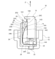
- FIG. 2 is a cross-sectional view illustrating a cross section of the tensioner cut along a line 2-2 illustrated in FIG. 1. It is an expanded side view which expands and shows the part of the axial direction one side of the tensioner of 1st Embodiment.
- FIG. 4 is an enlarged side view showing, on an enlarged scale, a portion on one side in the axial direction of the tensioner according to the first embodiment, showing a state in which a load on the other side in the axial direction is being input to the shaft.
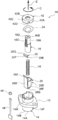
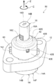
- It is a perspective view showing the tensioner of a 2nd embodiment. It is an exploded perspective view showing the tensioner of a 2nd embodiment exploded.
- the tensioner 10 is fixed to a cylinder block (not shown) of the engine via a flange 12, and is supported by the holder 14 and is movable along the holder 14. And a shaft 16.
- a cylinder block not shown
- the members inside the holder 14 are shown so as to be visible.
- hatching of the cross section is omitted.
- the tensioner 10 also has a coil spring 18 as a first urging member for urging the shaft 16 toward the timing chain or the timing belt, and allows the shaft 16 to move to one side and to move to the other side.
- a limiting pair of latches 20 Further, the tensioner 10 includes a pin 22 as a contact portion that rotatably (tilt) supports the pair of latches 20, a first leaf spring 24 as a third biasing member that rotationally biases the pair of latches 20, It has.
- the tensioner 10 includes a second leaf spring 26 as a second urging member that is deformed when a load from the timing chain or the timing belt is input to the shaft 16, a second leaf spring 26, and a pin 22. And a pair of slides 28 as intermediate members provided therebetween.
- the holder 14 is formed in a bottomed cylindrical shape extending in the axial direction of the holder 14 (hereinafter, simply referred to as “axial direction Z”). Specifically, the holder 14 includes a tubular portion 14A formed in a tubular shape and arranged at both ends in the circumferential direction C around the axial direction Z so as to be spaced apart from each other. Further, the holder 14 includes a bottom wall portion 14B provided to close the other side (the side opposite to the arrow Z direction) of the cylindrical portion 14A in the axial direction Z. Then, the fixing screw 30 inserted into the flange 12 is screwed to the bottom wall portion 14B, so that the flange 12 is fixed to the holder 14. Although the present embodiment has been described as being fixed with screws, it may be fixed using other methods such as caulking, press-fitting, and welding.
- the holder 14 includes a pair of pins and a slide support portion 14C that protrude from both ends of the cylindrical portion 14A in the circumferential direction C toward the outside of the cylindrical portion 14A and that are arranged to face each other in the circumferential direction C. ing.
- a slide housing recess 14 ⁇ / b> D in which a pair of slides 28 described later is housed is formed on one side of the pair of pins and the slide support portion 14 ⁇ / b> C in the axial direction Z (the side in the arrow Z direction). ing.
- a side opposite to the cylindrical portion 14A and a side of the other pin and the slide support portion 14C in the slide receiving recess 14D formed in the one pin and the slide support portion 14C are open. Further, the side opposite to the cylindrical portion 14A and the side of the one pin and the slide support portion 14C in the slide receiving recess 14D formed in the other pin and the slide support portion 14C are open.
- the slide 28 can be moved in a direction orthogonal to the axial direction Z by disposing the slide 28 in the slide receiving recess 14D.
- a through-hole 14E through which a pin 22 described later is inserted is formed in a portion of the pair of pins and the slide support portion 14C where the slide housing recess 14D is formed, on the side of the cylindrical portion 14A.
- the through hole 14E has a long hole shape whose longitudinal direction is the axial direction Z.
- a coil spring 18 is disposed inside the cylindrical portion 14 ⁇ / b> A of the holder 14 and inside a shaft 16 described later, and the coil spring 18 extends in the axial direction Z. It is possible to shrink.
- the shaft is urged by the coil spring.
- the shaft may be urged by hydraulic pressure.
- the shaft 16 is formed in a bottomed cylindrical shape in which the other side in the axial direction Z of the shaft 16 is open and one side in the axial direction Z is closed.
- the shaft 16 includes a cylindrical side wall 16A and a top wall 16B that closes one end of the side wall 16A in the axial direction Z.
- the shaft 16 is supported by the holder 14 so as to be movable in the axial direction Z by inserting the side wall portion 16A of the shaft 16 into the cylindrical portion 14A of the holder 14.
- a plurality of engaged concave portions 16C are formed on the outer peripheral portion of the side wall portion 16A.
- the plurality of engaged concave portions 16C are arranged along the axial direction Z at a predetermined pitch.
- the latch 20 is formed with a shaft support hole 20A through which a pin 22 described later is inserted.
- a portion of the latch 20 on one side of the portion where the shaft support hole 20A is formed is a leaf spring contact portion 20B with which a first leaf spring 24 described later contacts.
- an engagement protrusion 20C is formed which is engaged with a plurality of engaged recesses 16C formed on the shaft 16. ing.
- the engagement projection 20C of one latch 20 and the engagement projection 20C of the other latch 20 are arranged at positions different by a half pitch in the axial direction Z, so that The engaging projection 20C of the latch 20 and the engaging projection 20C of the other latch 20 do not simultaneously engage with the plurality of engaged recesses 16C formed on the shaft 16. That is, the engagement projection 20C of one latch 20 and the engagement projection 20C of the other latch 20 are alternately engaged with a plurality of engaged recesses 16C formed on the shaft 16 as the shaft 16 moves.
- the latch 20 is provided with a release piece 20D that is pressed by the operator.
- the engaging projection 20C is pulled out of the engaged recess 16C formed on the shaft 16.
- two latches are provided, but one or three or more latches may be provided.
- the first leaf spring 24 is formed by subjecting a steel plate material to press working, quenching, or the like, and the first leaf spring 24 is formed in an L-shaped bent shape.
- the first leaf spring 24 includes a base 24A fixed to the bottom wall 14B of the holder 14 via the fixing pin 22 and a flexure extending from the end of the base 24A to one side in the axial direction Z. A part 24B.
- the latch 20 contacts the leaf spring contact portions 20B of the pair of latches 20 in a state in which the bending portion 24B is bent (curved), so that the latching projection 20C of the latch 20 Is rotationally urged to the side that engages with the plurality of engaged recesses 16C formed at the bottom.
- the present embodiment has been described as being fixed by the fixing pin, it may be fixed by using other methods such as screws, caulking, press-fitting, welding, or may be fixed together with the holder.
- the pin 22 is formed in a bar shape, and a central portion in the longitudinal direction of the pin 22 rotatably supports a pair of adjacent latches 20. . Further, both side portions of the pin 22 supporting the pair of latches 20 are formed as slide opposing portions 22A which are arranged to oppose a pair of slides 28 described later. Since the cross section of the slide opposing portion 22A is a D-cut cross section, the slide opposing portion 22A and a slide 28 described later come into surface contact. In the present embodiment, a part of the pin has been described as having a D cut. However, the D cut may not be provided, or the D cut may be provided over the entire length of the pin.
- both sides of the pin 22 in the longitudinal direction are respectively inserted through a pair of pins of the holder 14 and through holes 14E formed in the slide support portion 14C.
- the pin 22 is prevented from being pulled out of the through hole 14E by locking a split pin (not shown) or the like to the pin 22.
- the portion of the pin 22 that is inserted through the through hole 14E is referred to as an insertion portion 22B.
- the pin is described as being locked by the split pin.
- the pin may be locked using other methods such as caulking, bending, and a snap ring.
- the pair of slides 28 are formed in a block shape.
- a surface 28A of the pin 22 that comes into contact with the slide facing portion 22A is inclined toward the opposite side to the shaft 16 toward one side in the axial direction Z.
- a surface 28B of the slide 28 that contacts a second leaf spring 26 described later is substantially parallel to the axial direction Z.
- the second leaf spring 26 is formed by subjecting a steel plate material thicker than the first leaf spring 24 to press working, quenching, or the like. It is formed in an L-shaped bent shape. Specifically, the second leaf spring 26 is fixed to the base 12A while being sandwiched between the flange 12 and the bottom wall 14B of the holder 14, and one side in the axial direction Z from the end of the base 26A. And a bending portion 26B extending to the outside.
- the base 26A of the second leaf spring 26 and the base 24A of the first leaf spring 24 are overlapped in the axial direction Z, and the bent portion 26B of the second leaf spring 26 and the first leaf spring 24 Are arranged adjacent to each other in a direction orthogonal to the axial direction Z. Further, an end of the bending portion 26B of the second leaf spring 26 on the axial direction Z side is a slide abutment portion 26C that is formed to project toward the pair of slides 28. When the slide contact portion 26C is pressed by the pair of slides 28, the bending portion 26B of the second leaf spring 26 bends in the direction opposite to the shaft 16.
- first leaf spring and the second leaf spring are described as separate members, but the first leaf spring and the second leaf spring may be integrated.
- the shaft 16 is moved to one side in the axial direction Z with respect to the holder 14 by the urging force of the coil spring 18,
- the top wall portion 16B of the shaft 16 can be pressed against a timing chain, a timing belt, or the like, or a guide member that guides the timing chain, the timing belt, or the like.
- the tension of the timing chain and the like is maintained.
- the engaging projection 20 ⁇ / b> C of the latch 20 is pressed from the engaged recess 16 ⁇ / b> C formed on the shaft 16.
- the latch 20 is turned against the urging force of the first leaf spring 24. Accordingly, the engagement protrusion 20C of the latch 20 sequentially comes out of the engagement recess 16C of the shaft 16, thereby allowing the shaft 16 to move to one side in the axial direction Z.
- the insertion portion 22B of the pin 22 that supports the pair of latches 20 is inserted into the through hole 14E of the holder 14. Is located at one end in the axial direction Z.
- a large load may be input to the top wall 16B of the shaft 16. That is, the top wall portion 16B of the shaft 16 may be pressed with a large load toward the other side in the axial direction Z.
- the large load input to the top wall portion 16B of the shaft 16 is, for example, a load that exceeds 10 times the load for urging the shaft 16 to one side in the axial direction Z by the coil spring 18.
- the preload is input to the pair of slides 28 from the slide contact portion 26C of the second leaf spring 26. Therefore, the load that the pair of slides 28 presses against the slide contact portion 26C of the second leaf spring 26 is smaller than the preload input to the pair of slides 28 from the slide contact portion 26C of the second leaf spring 26.
- the bending portion 26B of the second leaf spring 26 is not deformed. Accordingly, a biasing force F2 (drag F2) is generated in the latch 20 toward one side in the axial direction Z corresponding to the load F1.
- the sliding contact portion of the second leaf spring 26 is configured such that the biasing force F2 is greater than the load that biases the shaft 16 to one side in the axial direction Z by the coil spring 18.
- Preload and the like from 26C to a pair of slides 28 are set.
- the latch 20 is moved to the other side in the axial direction Z while being urged by the urging force F2 corresponding to the added load.
- the latch 20 is moved in the axial direction Z until the insertion portion 22B of the pin 22 supporting the pair of latches 20 contacts the other end in the axial direction Z in the through hole 14E of the holder 14. Can be moved to the other side of
- the coil spring 18 moves the shaft 16 to one side in the axial direction Z. It is possible to allow the latch 20 and the shaft 16 to move to the other side in the axial direction Z while urging the latch 20 and the shaft 16 with a load (urging force F2) larger than the load urging the latch 20 and the shaft 16. With this configuration, even if the urging force of the coil spring 18 that urges the shaft 16 to one side in the axial direction Z is set to be weak, the shaft 16 is not affected when a load applied to the other side in the axial direction Z is large. 16 can be allowed to move to the other side in the axial direction Z.
- the surface 28A of the slide 28 that comes into contact with the slide opposing portion 22A of the pin 22 is inclined toward the opposite side to the shaft 16 toward one side in the axial direction Z, so that a pair of slides is formed.
- the bending portion 26B of the second leaf spring 26 is deformed (the urging force F2 increases) by an amount corresponding to the amount of movement of the shutter 28, the present invention is not limited to this.
- adjustment may be made so that a desired urging force F2 is generated.
- the second plate spring 26, the slide 28, and the pin 22 are used, and the coil spring 18 applies a load (biasing force F2) larger than the load for biasing the shaft 16 to one side in the axial direction Z.
- biasing force F2 a load
- the latch 20 and the shaft 16 are configured to be allowed to move to the other side in the axial direction Z while urging the latch 20 and the shaft 16
- the present invention is not limited to this.
- the elastic force accompanying the deformation of the second urging member having another configuration is directly or indirectly transmitted to the latch 20, so that the coil spring 18 urges the shaft 16 to one side in the axial direction Z.
- the latch 20 and the shaft 16 may be allowed to move to the other side in the axial direction Z while urging the latch 20 and the shaft 16 with a large load (urging force F2).
- the tensioner 40 of the present embodiment includes a holder 14 having a flange 12 fixed to a cylinder block of an engine (not shown), a holder 14 supported by the holder 14, and a holder 14.
- the shaft 16 is movable along the shaft 16, and the cap 42 is inserted into the shaft 16 and attached to the holder 14.
- the tensioner 40 also has a coil spring 18 as a first urging member that urges the shaft 16 toward the timing chain or the timing belt, and allows the shaft 16 to move to one side and to move to the other side.
- a single latch 20 for limiting. Note that, similarly to the tensioner 10 of the first embodiment, a configuration in which a plurality of latches 20 are provided may be employed.
- the tensioner 40 includes a first leaf spring 24 as a third urging member for urging the latch 20 toward the shaft 16.
- the tensioner 40 includes a second leaf spring 26 as a second urging member that is deformed when a load from the timing chain or the timing belt is input to the shaft 16.
- the holder 14 includes a holder main body portion 14F formed in a bottomed cylindrical shape extending in the axial direction of the holder 14 (hereinafter, simply referred to as “axial direction Z”).
- the holder body 14F includes a cylindrical portion 14A formed in a cylindrical shape, and a bottom wall portion 14B provided so as to close the other side (opposite to the arrow Z direction) of the cylindrical portion 14A in the axial direction Z. , Is provided.
- a portion of the inner peripheral portion of the cylindrical portion 14A on the other side in the axial direction Z is a fitted portion 14G to which a fitting portion 26D of the second leaf spring 26 described later fits.
- a spring arrangement groove 14H in which a later-described flexible portion 26B of a second leaf spring 26 and a latch support portion 26E are arranged has an axial line. It is formed along the direction Z.
- the surfaces (bottom surfaces) of the second plate spring 26 that face the bending portion 26B and the latch supporting portion 26E in the thickness direction extend along the bending portion 26B and the latch supporting portion 26E. .
- the bottom surface H1 facing the bending portion 26B in the spring placement groove 14H extends in the axial direction Z, and the bottom surface H2 facing the latch support portion 26E in the spring placement groove 14H moves to one side in the axial direction Z. As it goes, it extends obliquely to the opposite side to the shaft 16.
- the flange portion 12 protrudes radially outward of the cylindrical portion 14A from an intermediate portion of the outer peripheral portion of the cylindrical portion 14A in the axial direction Z.
- a stopper insertion hole 141 is formed at the center of the bottom wall portion 14B, through which a stopper 44 (see FIG. 6) described later is inserted and closed by a seal plug 46.
- the cap 42 is formed in a bottomed cylindrical shape whose other side in the axial direction Z is open.
- the cap 42 includes a locking wall portion 42A formed in a cylindrical shape, and a lid wall portion 42B provided to close one side of the locking wall portion 42A in the axial direction Z.
- a shaft insertion hole 42C into which the shaft 16 described later is inserted is formed in the lid wall portion 42B. Then, the cap 42 is attached to the holder 14 by locking the locking wall portion 42A of the cap 42 to one end in the axial direction Z of the outer peripheral portion of the cylindrical portion 14A of the holder 14. ing.
- the distal end side (one side in the axial direction Z) of the shaft 16 projects through the shaft insertion hole 42 ⁇ / b> C of the cap 42.
- a notch-shaped access portion 42D is formed in a part of the locking wall portion 42A. A tool (not shown) can be engaged with a later-described latch 20 through the access portion 42D.
- the shaft 16 is formed in a bottomed cylindrical shape in which the other side in the axial direction Z of the shaft 16 is open and one side in the axial direction Z is closed.
- the shaft 16 includes a cylindrical side wall 16A and a top wall 16B that closes one end of the side wall 16A in the axial direction Z. Then, by inserting the side wall portion 16A of the shaft 16 into the cylindrical portion 14A of the holder 14, the shaft 16 can be moved in the axial direction Z via the fitting portion 26D of the second leaf spring 26 to be described later. Supported.
- a plurality of engaged concave portions 16C are formed in the outer peripheral portion of the side wall portion 16A. The plurality of engaged concave portions 16C are arranged along the axial direction Z at a predetermined pitch. Further, a stopper locking hole 16D is formed in the top wall 16B to lock a tip of a stopper 44 described later.
- the latch 20 is formed in a prismatic shape extending along a direction orthogonal to the axial direction Z.
- an engagement projection 20C is formed which is engaged with a plurality of engagement recesses 16C formed on the shaft 16.
- the latch 20 has a locking hole 20E for locking a tool (not shown). Then, a tool (not shown) inserted from an access portion 42D (see FIG.
- the surface of the latch 20 opposite to the side wall portion 16A of the shaft 16 is a second leaf spring contact surface 20F that contacts a latch support portion 26E of a second leaf spring 26 described later.
- the second leaf spring contact surface 20F is inclined toward the side opposite to the side wall portion 16A of the shaft 16 toward one side in the axial direction Z.
- one surface of the latch 20 in the axial direction Z is a first leaf spring contact surface 20G with which a first leaf spring 24 described later contacts.
- the first leaf spring 24 is formed by subjecting a steel plate to press working, quenching, or the like. As viewed from Z, the shaft 16 is formed in an annular shape through which the shaft 16 is inserted. Since the first leaf spring 24 is disposed between the lid wall portion 42B of the cap 42 and the latch 20, the first leaf spring 24 moves the first leaf spring contact surface 20G of the latch 20 in the axial direction Z. To the other side. As a result, the latch 20 is biased toward the shaft 16 via the latch support 26E of the second leaf spring 26 described later. Note that a coil spring may be used instead of the first leaf spring 24, as in a tensioner 50 according to a third embodiment described later.
- the second leaf spring 26 is formed by subjecting a steel plate material thicker than the first leaf spring 24 to press working, quenching, or the like.
- the second leaf spring 26 includes a fitting portion 26D fitted to the fitted portion 14G of the holder 14, a bending portion 26B extending from the fitting portion 26D to one side in the axial direction Z, and a bending portion 26B.
- a latch support 26 ⁇ / b> E that extends from one end in the axial direction Z to the opposite side to the shaft 16.
- the fitting portion 26D is connected to the bottom wall portion 14B of the holder 14 from the other end of the C-shaped plate portion 26F in the axial direction Z from the other end of the C-shaped plate portion 26F. And a bottom plate portion 26G extending along.
- the outer diameter before the C-shaped plate portion 26F engages with the fitted portion 14G of the holder 14 is set to be larger than the inner diameter of the fitted portion 14G of the holder 14. . Accordingly, the outer dimensions of the C-shaped plate portion 26F are reduced to a size corresponding to the inner diameter of the fitted portion 14G of the holder 14 by the engagement of the C-shaped plate portion 26F with the fitted portion 14G of the holder 14. It is supposed to.
- the base end side of the shaft 16 is disposed inside the C-shaped plate portion 26F. This allows the shaft 16 to move in the axial direction Z along the C-shaped plate portion 26F.
- the bottom plate 26G has a stopper insertion hole 26H through which the stopper 44 (see FIG. 5) is inserted.
- the flexure 26B extends so that its thickness direction faces the shaft 16, whereby the flexure 26B flexes in the opposite direction to the shaft 16.
- the above-mentioned second leaf spring contact surface 20F of the latch 20 comes into contact with the latch supporting portion 26E, and is inclined toward the opposite side to the side wall portion 16A of the shaft 16 toward one side in the axial direction Z. doing.
- the coil spring 18 of the present embodiment is a coil spring having a round cross section. Most of the coil spring 18 is arranged inside the shaft 16 while being compressed in the axial direction Z.
- the shaft 16 is moved to one side in the axial direction Z with respect to the holder 14 by the urging force of the coil spring 18.
- the top wall portion 16B of the shaft 16 can be pressed against a timing chain, a timing belt, or the like, or a guide member that guides the timing chain, the timing belt, or the like.
- the tension of the timing chain and the like is maintained.
- the engaging projection 20 ⁇ / b> C of the latch 20 is pressed from the engaged recess 16 ⁇ / b> C formed on the shaft 16.
- the latch 20 is moved to one side in the axial direction Z and radially outward against the urging force of the first leaf spring 24 (the latch 20 is moved toward the second leaf spring against the urging force of the first leaf spring 24). 26 along the latch support 26E). As a result, the engagement protrusion 20C of the latch 20 comes out of the engagement recess 16C of the shaft 16, whereby the shaft 16 is allowed to move to one side in the axial direction Z.
- the latch 20 and the shaft 16 can move to the other side in the axial direction Z until the latch support portion 26E of the second leaf spring 26 contacts the bottom surface H2 of the spring arrangement groove 14H of the holder 14.
- the bottom surface H2 of the spring arrangement groove 14H functions as a stopper that restricts the movement of the shaft 16 to the other side in the axial direction Z.
- a tensioner 50 includes a holder 14 having a flange 12 fixed to a cylinder block of an engine (not shown), a holder 14 supported by the holder 14, and a holder 14.
- the shaft 16 is movable along the shaft 16, and the cap 42 is inserted into the shaft 16 and attached to the holder 14.
- the tensioner 50 also includes a main coil spring 53 as a first urging member for urging the shaft 16 toward the timing chain or the timing belt, and allows the shaft 16 to move to one side and to move to the other side. And a taper ring 52 as an intermediate member that supports the latch 20. Note that, similarly to the tensioner 10 of the first embodiment, a configuration in which a plurality of latches 20 are provided may be employed. Further, the tensioner 50 includes a first coil spring 54 as a third urging member for urging the latch 20 toward the shaft 16. Further, the tensioner 50 includes a second coil spring 56 as a second urging member that is deformed when a load from the timing chain or the timing belt is input to the shaft 16. Further, the tensioner 50 includes a collar 58 disposed between the holder 14 and the second coil spring 56.
- the holder 14 includes a holder main body 14 ⁇ / b> F formed in a cylindrical shape with a bottom and extending in the axial direction of the holder 14 (hereinafter, simply referred to as “axial direction Z”).
- the holder body 14F includes a cylindrical portion 14A formed in a cylindrical shape, and a bottom wall portion 14B provided so as to close the other side (opposite to the arrow Z direction) of the cylindrical portion 14A in the axial direction Z. , Is provided.
- a second coil spring 56 and a collar 58, which will be described later, are arranged on the inner peripheral portion of the cylindrical portion 14A. Further, a flange portion 12 protrudes radially outward of the cylindrical portion 14A from one end of the outer peripheral portion of the cylindrical portion 14A in the axial direction Z. Further, a locking groove 14J for locking a locking piece 42F of a cap 42, which will be described later, is formed at one end of the inner peripheral portion of the cylindrical portion 14A in the axial direction Z.
- the cap 42 is formed in a bottomed cylindrical shape whose other side in the axial direction Z is open.
- the cap 42 has a cylindrical wall portion 42E formed in a cylindrical shape, a lid wall portion 42B provided to close one side of the cylindrical wall portion 42E in the axial direction Z, and an axial direction Z in the cylindrical wall portion 42E.
- a locking piece 42F that protrudes radially outward of the cylindrical wall portion 42E from the other end.
- a shaft insertion hole 42C into which the shaft 16 described later is inserted is formed in the lid wall portion 42B.
- the locking piece 42F of the cap 42 is locked in the locking groove 14J of the holder 14, so that the cap 42 is attached to the holder 14.
- the locking piece 42F of the cap 42 is engaged with the locking groove 14J of the holder 14 from one side in the axial direction Z, and the cap 42 is rotated by a predetermined angle in the circumferential direction C.
- the locking of the locking piece 42F of the cap 42 into the locking groove 14J of the holder 14 is completed.
- a first coil spring 54 a base end side (the other side in the axial direction Z) of the shaft 16, a latch 20, a tapered ring 52, a main coil spring 53, and a second coil spring 56 described later.
- the distal end side (one side in the axial direction Z) of the shaft 16 passes through the shaft insertion hole 42 ⁇ / b> C of the cap 42. It is designed to protrude.
- An access portion 42D which is a rectangular opening, is formed in a part of the cylindrical wall portion 42E. A tool (not shown) can be engaged with a later-described latch 20 through the access portion 42D.
- the shaft 16 is formed in a bottomed cylindrical shape in which the other side in the axial direction Z of the shaft 16 is open and one side in the axial direction Z is closed. I have.
- the shaft 16 includes a cylindrical side wall 16A and a top wall 16B that closes one end of the side wall 16A in the axial direction Z.
- the shaft 16 is supported by the holder 14 so as to be movable in the axial direction Z by inserting the side wall portion 16A of the shaft 16 into the cylindrical portion 14A of the holder 14.
- a plurality of engaged concave portions 16C are formed in the outer peripheral portion of the side wall portion 16A.
- the plurality of engaged concave portions 16C are arranged along the axial direction Z at a predetermined pitch.
- a stopper locking hole 16D in which the tip of the stopper 44 is locked is formed in the top wall 16B.
- the latch 20 is formed in a prismatic shape extending along a direction orthogonal to the axial direction Z.
- an engagement projection 20C is formed which is engaged with a plurality of engagement recesses 16C formed on the shaft 16.
- the latch 20 has a locking hole 20E for locking a tool (not shown). Then, a tool (not shown) inserted from an access portion 42D (see FIG.
- the surface of the latch 20 opposite to the side wall 16A of the shaft 16 is a tapered ring contact surface 20F that contacts a latch support surface 52B of a tapered ring 52 described later.
- the tapered ring contact surface 20F is inclined toward the side opposite to the side wall 16A of the shaft 16 toward one side in the axial direction Z.
- one surface of the latch 20 in the axial direction Z is a first coil spring contact surface 20G with which a first coil spring 54 described later contacts.
- the tapered ring 52 is formed in an annular shape in which the shaft 16 is inserted through the axial center thereof when viewed from the axial direction Z.
- a latch engagement groove 52A with which the latch 20 is engaged is formed on one side of the tapered ring 52 in the axial direction.
- the surface of the latch engagement groove 52A where the tapered ring contact surface 20F of the latch 20 abuts is a latch support surface 52B. Further, the latch support surface 52B is inclined toward the side opposite to the side wall portion 16A of the shaft 16 toward one side in the axial direction Z.
- the first coil spring 54 is a coil spring having a round cross section.
- the first coil spring 54 is arranged between the latch 20 supported by the tapered ring 52 and the lid wall portion 42B of the cap 42 in a state of being compressed in the axial direction Z. Then, the first coil spring 54 presses the first coil spring contact surface 20G of the latch 20 toward the other side in the axial direction Z. As a result, the latch 20 is biased toward the shaft 16 via the latch support surface 52B of the tapered ring 52.
- a plate spring or a disc spring may be used instead of the first coil spring 54.
- a second coil spring 56 and a main coil spring 53 which will be described later may be plate springs or disc springs.
- the cross-sectional shape of the first coil spring 54, the second coil spring 56, and the main coil spring 53 may be a round-shaped coil spring or a square-shaped coil spring.
- the type and cross-sectional shape of the spring may be appropriately selected in consideration of the required load.
- the second coil spring 56 is a rectangular coil spring.
- the second coil spring 56 is disposed in the outer peripheral portion of the shaft 16 and inside the cylindrical portion 14A of the holder 14 in a state of being compressed in the axial direction Z between the bottom wall portion 14B of the holder 14 and the tapered ring 52. I have.
- the main coil spring 53 of the present embodiment is a coil spring having a round cross section. Most of the main coil spring 53 is arranged inside the shaft 16 while being compressed in the axial direction Z.
- the collar 58 is formed in a cylindrical shape in which the second coil spring 56 is disposed on the inner peripheral portion.
- the collar 58 is arranged along the outer peripheral portion of the second coil spring 56 and along the inner surface of the cylindrical portion 14A of the holder 14. Further, an end face 58A on one side in the axial direction Z of the collar 58 faces the tapered ring 52 in the axial direction Z.
- the shaft 16 moves to one side in the axial direction Z with respect to the holder 14 by the biasing force of the main coil spring 53.
- This allows the top wall portion 16B of the shaft 16 to be pressed against a timing chain, a timing belt, or the like, or a guide member that guides the timing chain, the timing belt, or the like.
- the tension of the timing chain and the like is maintained.
- the engaging projection 20 ⁇ / b> C of the latch 20 is pressed from the engaged recess 16 ⁇ / b> C formed on the shaft 16.
- the latch 20 is moved to one side in the axial direction Z and radially outward against the urging force of the first coil spring 54 (the latch 20 supports the latch of the tapered ring 52 against the urging force of the first coil spring 54). Moved along surface 52B). As a result, the engagement protrusion 20C of the latch 20 comes out of the engagement recess 16C of the shaft 16, whereby the shaft 16 is allowed to move to one side in the axial direction Z.
- the latch 20 and the shaft 16 can move to the other side in the axial direction Z until the taper ring 52 comes into contact with the end face 58A on one side in the axial direction Z of the collar 58. That is, in the present embodiment, the collar 58 functions as a stopper that restricts the movement of the shaft 16 to the other side in the axial direction Z.
- the respective spring characteristics of the first coil spring 54 and the second coil spring 56 can be easily adjusted as compared with the case where the first coil spring 54 and the second coil spring 56 are plate springs.
Landscapes
- Engineering & Computer Science (AREA)
- General Engineering & Computer Science (AREA)
- Mechanical Engineering (AREA)
- Devices For Conveying Motion By Means Of Endless Flexible Members (AREA)
Abstract
テンショナは、軸線方向に沿って移動可能に支持されたシャフトと、シャフトを軸線方向一方側へ付勢するコイルバネと、シャフトに係合することで、シャフトの軸線方向他方側への移動を制限するラッチと、を備えている。また、テンショナは、軸線方向他方側への荷重がシャフトへ入力された際に、コイルバネがシャフトを付勢する付勢力よりも大きな付勢力でラッチを軸線方向一方側へ付勢しながらラッチ及びシャフトの軸線方向他方側への移動を許容する第2板バネを備えている。
Description
本開示は、チェーンやベルトの張力を保つために用いられるテンショナに関する。
実開昭62-13257号公報及び特開平8-226503号公報には、タイミングチェーンを押圧することによって、タイミングチェーンの張力を保つテンショナが開示されている。これらの文献に記載されたテンショナは、所謂ラチェットタイプのテンショナであり、スプリングによってタイミングチェーン側へ付勢されたシャフト(テンションロッド、プランジャ)と、シャフトに係合することで当該シャフトのタイミングチェーンとは反対側への移動を制限するラッチ(ラチェット爪)と、を備えている。そして、これらの文献に記載されたテンショナでは、タイミングチェーンの張り過ぎに伴う異音の発生やフリクションの増加を抑制するために、タイミングチェーンを押圧するシャフトがラッチと共にタイミングチェーンとは反対側へ移動するようになっている。
ところで、フリクションの増加を抑制するという観点では、シャフトをタイミングチェーン側へ付勢するスプリング(付勢部材)の付勢力を弱く設定することが望ましい。しかしながら、スプリングの付勢力を弱く設定すると、実開昭62-13257号公報及び特開平8-226503号公報に記載された構成では、タイミングチェーンからシャフトへ入力される荷重が小さい場合においても、シャフトがラッチと共にタイミングチェーンとは反対側へ移動してしまう。
上記事実を考慮し、シャフトを軸線方向一方側へ付勢する付勢部材の付勢力を弱く設定できると共に、シャフトへ入力される軸線方向他方側への荷重が大きい場合に当該シャフトの軸線方向他方側への移動を許容することができるテンショナを得ることが目的である。
上記課題を解決するテンショナは、軸線方向に沿って移動可能に支持されたシャフトと、前記シャフトを軸線方向一方側へ付勢する第1付勢部材と、前記シャフトに係合することで、該シャフトの軸線方向他方側への移動を制限するラッチと、前記第1付勢部材が前記シャフトを軸線方向一方側に付勢するよりも大きな付勢力を有するとともに、軸線方向他方側への荷重が前記シャフトに入力されたときに、前記ラッチおよび前記シャフトの軸線方向他方側への移動を許容するように前記ラッチを付勢する第2付勢部材と、を備えている。
上記テンショナは、シャフトを軸線方向一方側へ付勢する付勢部材の付勢力を弱く設定できると共に、シャフトへ入力される軸線方向他方側への荷重が大きい場合に当該シャフトの軸線方向他方側への移動を許容することができる。
(第1実施形態のテンショナ)
図1~図4を用いて第1実施形態に係るテンショナについて説明する。
図1~図4を用いて第1実施形態に係るテンショナについて説明する。
図1及び図2に示されるように、テンショナ10は、図示しないエンジンのシリンダブロックにフランジ12を介して固定されるホルダ14と、ホルダ14に支持されていると共に当該ホルダ14に沿って移動可能とされたシャフト16と、を備えている。なお、図1においては、ホルダ14の内部の部材が見えるように図示している。また、図2においては、断面のハッチングを省略している。
また、テンショナ10は、シャフト16をタイミングチェーンやタイミングベルト側に向けて付勢する第1付勢部材としてのコイルバネ18と、シャフト16の一方側への移動を許容すると共に他方側への移動を制限する一対のラッチ20と、を備えている。さらに、テンショナ10は、一対のラッチ20を回転(傾動)可能に支持する接触部としてのピン22と、一対のラッチ20を回転付勢する第3付勢部材としての第1板バネ24と、を備えている。また、テンショナ10は、タイミングチェーンやタイミングベルト側からの荷重がシャフト16へ入力された際に変形される第2付勢部材としての第2板バネ26と、第2板バネ26とピン22との間に設けられた中間部材としての一対のスライド28と、を備えている。
(ホルダ14の構成)
ホルダ14は、当該ホルダ14の軸線方向(以下、単に「軸線方向Z」という)に延びる有底筒状に形成されている。具体的には、ホルダ14は、軸線方向Zまわりの周方向Cの両端が離間して配置され軸線方向Zに沿って延在する筒状に形成された筒部14Aを備えている。また、ホルダ14は、筒部14Aにおける軸線方向Zの他方側(矢印Z方向とは反対側)を閉止するように設けられた底壁部14Bを備えている。そして、フランジ12に挿通された固定ネジ30が底壁部14Bに螺合されることで、フランジ12がホルダ14に固定されるようになっている。なお、本実施形態ではネジにより固定するものとして説明したが、カシメ・圧入・溶接等のその他の方法を用いて固定してもよい。
ホルダ14は、当該ホルダ14の軸線方向(以下、単に「軸線方向Z」という)に延びる有底筒状に形成されている。具体的には、ホルダ14は、軸線方向Zまわりの周方向Cの両端が離間して配置され軸線方向Zに沿って延在する筒状に形成された筒部14Aを備えている。また、ホルダ14は、筒部14Aにおける軸線方向Zの他方側(矢印Z方向とは反対側)を閉止するように設けられた底壁部14Bを備えている。そして、フランジ12に挿通された固定ネジ30が底壁部14Bに螺合されることで、フランジ12がホルダ14に固定されるようになっている。なお、本実施形態ではネジにより固定するものとして説明したが、カシメ・圧入・溶接等のその他の方法を用いて固定してもよい。
また、ホルダ14は、筒部14Aにおける周方向Cの両端から当該筒部14Aの外側に向けてそれぞれ突出すると共に互いに周方向Cに対向して配置された一対のピン及びスライド支持部14Cを備えている。
図3に示されるように、一対のピン及びスライド支持部14Cにおける軸線方向Zの一方側(矢印Z方向側)には、後述する一対のスライド28がそれぞれ収容されるスライド収容凹部14Dが形成されている。一方のピン及びスライド支持部14Cに形成されたスライド収容凹部14Dにおける筒部14Aとは反対側及び他方のピン及びスライド支持部14C側は開放されている。また、他方のピン及びスライド支持部14Cに形成されたスライド収容凹部14Dにおける筒部14Aとは反対側及び一方のピン及びスライド支持部14C側は開放されている。そして、スライド28がスライド収容凹部14D内に配置されることで、当該スライド28が軸線方向Zと直交する方向に移動可能となっている。
一対のピン及びスライド支持部14Cにおいてスライド収容凹部14Dが形成された部分の筒部14A側には、後述するピン22が挿通される貫通孔14Eがそれぞれ形成されている。この貫通孔14Eは、軸線方向Zを長手方向とする長孔状となっている。
また、図1及び図2に示されるように、ホルダ14の筒部14Aの内部でかつ後述するシャフト16の内部には、コイルバネ18が配置されており、このコイルバネ18は、軸線方向Zに伸び縮みすることが可能とされている。なお、本実施例ではコイルバネによりシャフトを付勢するものとして説明したが、油圧によりシャフトを付勢してもよい。
(シャフト16の構成)
図1及び図2に示されるように、シャフト16は、当該シャフト16の軸線方向Zの他方側が開放されていると共に軸線方向Zの一方側が閉止された有底筒状に形成されている。このシャフト16は、円筒状の側壁部16Aと、側壁部16Aの軸線方向Zの一方側の端部を閉止する頂壁部16Bと、を備えている。そして、シャフト16の側壁部16Aがホルダ14の筒部14Aに挿入されることで、シャフト16がホルダ14に軸線方向Zに移動可能に支持されている。また、図2に示されるように、側壁部16Aの外周部には、複数の被係合凹部16Cが形成されている。この複数の被係合凹部16Cは、所定のピッチで軸線方向Zに沿って配列されている。
図1及び図2に示されるように、シャフト16は、当該シャフト16の軸線方向Zの他方側が開放されていると共に軸線方向Zの一方側が閉止された有底筒状に形成されている。このシャフト16は、円筒状の側壁部16Aと、側壁部16Aの軸線方向Zの一方側の端部を閉止する頂壁部16Bと、を備えている。そして、シャフト16の側壁部16Aがホルダ14の筒部14Aに挿入されることで、シャフト16がホルダ14に軸線方向Zに移動可能に支持されている。また、図2に示されるように、側壁部16Aの外周部には、複数の被係合凹部16Cが形成されている。この複数の被係合凹部16Cは、所定のピッチで軸線方向Zに沿って配列されている。
(ラッチ20の構成)
図1及び図2に示されるように、一対のラッチ20はブロック状に形成されている。なお、一方のラッチ20と他方のラッチ20とは、ほぼ同様の構成とされているため、ここでは一方のラッチ20の構成について説明する。
図1及び図2に示されるように、一対のラッチ20はブロック状に形成されている。なお、一方のラッチ20と他方のラッチ20とは、ほぼ同様の構成とされているため、ここでは一方のラッチ20の構成について説明する。
ラッチ20には、後述するピン22が挿通される軸支孔20Aが形成されている。また、ラッチ20において軸支孔20Aが形成された部分に対して一方側の部分は、後述する第1板バネ24が当接する板バネ当接部20Bとされている。また、ラッチ20において軸支孔20Aが形成された部分に対して他方側の部分には、シャフト16に形成された複数の被係合凹部16Cに係合される係合凸部20Cが形成されている。そして、この係合凸部20Cがシャフト16に形成された複数の被係合凹部16Cに係合されることで、シャフト16のホルダ14に対する軸線方向Zの他方側への移動が制限されるようになっている。なお、本実施形態では、一方のラッチ20の係合凸部20Cと他方のラッチ20の係合凸部20Cとが、軸線方向Zにハーフピッチだけ異なる位置に配置されていることにより、一方のラッチ20の係合凸部20Cと他方のラッチ20の係合凸部20Cとが、シャフト16に形成された複数の被係合凹部16Cに同時に係合しないようになっている。すなわち、一方のラッチ20の係合凸部20Cと他方のラッチ20の係合凸部20Cとが、シャフト16の移動に伴い当該シャフト16に形成された複数の被係合凹部16Cに交互に係合されるようになっている。なお、ラッチ20には、作業者によって押圧される解除片部20Dが設けられている。この解除片部20Dが押圧されて、ラッチ20が回転(傾動)されることで、係合凸部20Cがシャフト16に形成された被係合凹部16Cから抜出すようになっている。なお、本実施例ではラッチを2つ設けるものとして説明したが、ラッチを1つもしくは3つ以上設けてもよい。
(第1板バネ24の構成)
第1板バネ24は、鋼板材にプレス加工や焼入れ等が施されることによって形成されており、この第1板バネ24は、L字状に曲げられた形状に形成されている。具体的には、第1板バネ24は、ホルダ14の底壁部14Bに固定ピン22を介して固定される基部24Aと、基部24Aの端部から軸線方向Zの一方側へ延出する撓み部24Bと、を備えている。そして、撓み部24Bが撓んだ状態(湾曲された状態)で一対のラッチ20の板バネ当接部20Bに当接することで、ラッチ20が、当該ラッチ20の係合凸部20Cがシャフト16に形成された複数の被係合凹部16Cへ係合する側へ回転付勢されるようになっている。なお、本実施例では固定ピンにより固定するものとして説明したが、ネジ・カシメ・圧入・溶接等のその他の方法を用いて固定してもよいし、ホルダと一括して固定してもよい。
第1板バネ24は、鋼板材にプレス加工や焼入れ等が施されることによって形成されており、この第1板バネ24は、L字状に曲げられた形状に形成されている。具体的には、第1板バネ24は、ホルダ14の底壁部14Bに固定ピン22を介して固定される基部24Aと、基部24Aの端部から軸線方向Zの一方側へ延出する撓み部24Bと、を備えている。そして、撓み部24Bが撓んだ状態(湾曲された状態)で一対のラッチ20の板バネ当接部20Bに当接することで、ラッチ20が、当該ラッチ20の係合凸部20Cがシャフト16に形成された複数の被係合凹部16Cへ係合する側へ回転付勢されるようになっている。なお、本実施例では固定ピンにより固定するものとして説明したが、ネジ・カシメ・圧入・溶接等のその他の方法を用いて固定してもよいし、ホルダと一括して固定してもよい。
(ピン22の構成)
図2及び図3に示されるように、ピン22は棒状に形成されており、このピン22の長手方向の中央部位は、隣り合って配置された一対のラッチ20を回転自在に支持している。また、ピン22において一対のラッチ20を支持している部分の両側部分は、後述する一対のスライド28と対向して配置されるスライド対向部22Aとされている。このスライド対向部22Aの断面がDカット状の断面とされていることにより、スライド対向部22Aと後述するスライド28とが面接触するようになっている。なお、本実施例ではピンの一部がDカットを有するものとして説明したが、Dカットがなくてもよいし、ピンの全長にわたってDカットを設けてもよい。
図2及び図3に示されるように、ピン22は棒状に形成されており、このピン22の長手方向の中央部位は、隣り合って配置された一対のラッチ20を回転自在に支持している。また、ピン22において一対のラッチ20を支持している部分の両側部分は、後述する一対のスライド28と対向して配置されるスライド対向部22Aとされている。このスライド対向部22Aの断面がDカット状の断面とされていることにより、スライド対向部22Aと後述するスライド28とが面接触するようになっている。なお、本実施例ではピンの一部がDカットを有するものとして説明したが、Dカットがなくてもよいし、ピンの全長にわたってDカットを設けてもよい。
また、ピン22の長手方向の両側部分は、ホルダ14の一対のピン及びスライド支持部14Cにそれぞれ形成された貫通孔14Eにそれぞれ挿通されている。なお、図示しない割ピン等がピン22に係止されること等により、ピン22が貫通孔14Eから抜出すことが防止されている。ここで、ピン22において貫通孔14Eに挿通されている部分を挿通部22Bと呼ぶ。なお、本実施例ではピンが割ピンにより係止されているものとして説明したが、カシメ・曲げ・止輪等のその他の方法を用いて係止してもよい。
(スライド28の構成)
図3に示されるように、一対のスライド28はブロック状に形成されている。このスライド28においてピン22のスライド対向部22Aと接触する面28Aは、軸線方向Zの一方側へ向かうにつれてシャフト16とは反対側へ傾斜している。また、スライド28において後述する第2板バネ26と接触する面28Bは、軸線方向Zと略平行となっている。なお、本実施例では一対のスライドを設けることとして説明したが、ラッチ回動の妨げにならなければスライドを一対とせず一体としてもよい。
図3に示されるように、一対のスライド28はブロック状に形成されている。このスライド28においてピン22のスライド対向部22Aと接触する面28Aは、軸線方向Zの一方側へ向かうにつれてシャフト16とは反対側へ傾斜している。また、スライド28において後述する第2板バネ26と接触する面28Bは、軸線方向Zと略平行となっている。なお、本実施例では一対のスライドを設けることとして説明したが、ラッチ回動の妨げにならなければスライドを一対とせず一体としてもよい。
(第2板バネ26の構成)
図2に示されるように、第2板バネ26は、第1板バネ24よりも厚い鋼板材にプレス加工や焼入れ等が施されることによって形成されており、この第2板バネ26は、L字状に曲げられた形状に形成されている。具体的には、第2板バネ26は、フランジ12とホルダ14の底壁部14Bとの間に挟み込まれた状態で固定される基部26Aと、基部26Aの端部から軸線方向Zの一方側へ延出する撓み部26Bと、を備えている。本実施形態では、第2板バネ26の基部26Aと第1板バネ24の基部24Aとが、軸線方向Zに重ねられていると共に、第2板バネ26の撓み部26Bと第1板バネ24の撓み部24Bとが、軸線方向Zと直交する方向に隣り合って配置されている。また、第2板バネ26の撓み部26Bにおける軸線方向Z側の端部は、一対のスライド28側へ凸状に形成されたスライド当接部26Cとされている。このスライド当接部26Cが一対のスライド28によって押圧されることで、第2板バネ26の撓み部26Bがシャフト16とは反対方向へ撓むようになっている。また、本実施形態では、第2板バネ26のスライド当接部26Cから一対のスライド28へ予荷重が入力されるように、第2板バネ26の成形時の寸法等が設定されている。なお、本実施例では第1板バネと第2板バネを別部材として説明したが、第1板バネと第2板バネを一体としてもよい。
図2に示されるように、第2板バネ26は、第1板バネ24よりも厚い鋼板材にプレス加工や焼入れ等が施されることによって形成されており、この第2板バネ26は、L字状に曲げられた形状に形成されている。具体的には、第2板バネ26は、フランジ12とホルダ14の底壁部14Bとの間に挟み込まれた状態で固定される基部26Aと、基部26Aの端部から軸線方向Zの一方側へ延出する撓み部26Bと、を備えている。本実施形態では、第2板バネ26の基部26Aと第1板バネ24の基部24Aとが、軸線方向Zに重ねられていると共に、第2板バネ26の撓み部26Bと第1板バネ24の撓み部24Bとが、軸線方向Zと直交する方向に隣り合って配置されている。また、第2板バネ26の撓み部26Bにおける軸線方向Z側の端部は、一対のスライド28側へ凸状に形成されたスライド当接部26Cとされている。このスライド当接部26Cが一対のスライド28によって押圧されることで、第2板バネ26の撓み部26Bがシャフト16とは反対方向へ撓むようになっている。また、本実施形態では、第2板バネ26のスライド当接部26Cから一対のスライド28へ予荷重が入力されるように、第2板バネ26の成形時の寸法等が設定されている。なお、本実施例では第1板バネと第2板バネを別部材として説明したが、第1板バネと第2板バネを一体としてもよい。
(本実施形態の作用並びに効果)
次に、本実施形態の作用並びに効果について説明する。
次に、本実施形態の作用並びに効果について説明する。
図1、図2及び図3に示されるように、以上説明したテンショナ10によれば、コイルバネ18の付勢力によってシャフト16がホルダ14に対して軸線方向Zの一方側へ移動されることで、当該シャフト16の頂壁部16Bをタイミングチェーンやタイミングベルト等又はタイミングチェーンやタイミングベルト等をガイドするガイド部材に押し付けることができる。これにより、タイミングチェーン等の張力が保たれる。ここで、シャフト16がホルダ14に対して軸線方向Zの一方側へ移動される際においては、シャフト16に形成された被係合凹部16C側からラッチ20の係合凸部20Cが押圧されて、ラッチ20が第1板バネ24の付勢力に抗して回動される。これにより、ラッチ20の係合凸部20Cがシャフト16の被係合凹部16Cから順次抜け出すことで、シャフト16の軸線方向Zの一方側への移動が許容されている。
ここで、タイミングチェーン等からシャフト16の頂壁部16Bに後述する大きな荷重が入力される前の状態では、一対のラッチ20を支持するピン22の挿通部22Bは、ホルダ14の貫通孔14E内における軸線方向Zの一方側の端部に位置している。
また、エンジンの回転数変動(トルク変動)や温度変化等によって、タイミングチェーン等の張りが変化すると、シャフト16の頂壁部16Bに大きな荷重が入力される場合がある。すなわち、シャフト16の頂壁部16Bが軸線方向Zの他方側へ向けて大きな荷重で押圧される場合がある。ここで、シャフト16の頂壁部16Bに入力される大きな荷重とは、一例として、コイルバネ18がシャフト16を軸線方向Zの一方側へ付勢する荷重の10倍を超える荷重のことである。
図2及び図3に示されるように、シャフト16の頂壁部16Bが軸線方向Zの他方側へ向けて大きな荷重F1で押圧されると、この荷重F1が、ラッチ20、ピン22を介して一対のスライド28に入力される。これにより、一対のスライド28が第2板バネ26のスライド当接部26Cを押圧する。
ここで、本実施形態では、第2板バネ26のスライド当接部26Cから一対のスライド28へ予荷重が入力されている。そのため、一対のスライド28が第2板バネ26のスライド当接部26Cを押圧する荷重が、第2板バネ26のスライド当接部26Cから一対のスライド28へ入力される予荷重よりも小さい荷重の場合においては、第2板バネ26の撓み部26Bは変形されない。従って、ラッチ20には、上記荷重F1と対応する軸線方向Zの一方側への付勢力F2(抗力F2)が生じることになる。ここで、本実施形態では、この付勢力F2が、コイルバネ18がシャフト16を軸線方向Zの一方側へ付勢する荷重よりも大きな荷重となるように、第2板バネ26のスライド当接部26Cから一対のスライド28への予荷重等が設定されている。なお、本実施例では第2板バネからスライドに予荷重が入力されているものとして説明したが、予荷重は入力されていなくてもよい。
また、一対のスライド28が第2板バネ26のスライド当接部26Cを押圧する荷重が、第2板バネ26のスライド当接部26Cから一対のスライド28へ入力される予荷重よりも大きい場合においては、図4に示されるように、ラッチ20を支持するピン22が一対のスライド28と摺動しながら軸線方向Zの他方側へ移動される。これにより、ラッチ20の軸線方向Zの他方側への移動が許容されて、シャフト16の軸線方向Zの他方側への移動が許容される。その結果、タイミングチェーン等を張り過ぎることによるフリクションの増加を抑制することができる。
また、ラッチ20を支持するピン22が一対のスライド28と摺動しながら軸線方向Zの他方側へ移動されると、一対のスライド28がシャフト16とは反対側へ移動しながら第2板バネ26のスライド当接部26Cを押圧する。これにより、一対のスライド28の移動量に対応する量だけ第2板バネ26の撓み部26Bが変形される。これにより、第2板バネ26のスライド当接部26Cから一対のスライド28へ入力される予荷重と第2板バネ26の撓み部26Bの変形に伴う弾性力とを足し合わせた荷重が、一対のスライド28及びピン22を介してラッチ20に伝達される。その結果、ラッチ20が、上記足し合わせた荷重に対応する付勢力F2で付勢されながら軸線方向Zの他方側へ移動されることになる。なお、本実施形態では、一対のラッチ20を支持するピン22の挿通部22Bがホルダ14の貫通孔14E内における軸線方向Zの他方側の端部に接触する位置まで、ラッチ20が軸線方向Zの他方側へ移動可能となっている
以上説明したように、本実施形態では、シャフト16の頂壁部16Bが軸線方向Zの他方側へ向けて大きな荷重F1で押圧された際に、コイルバネ18がシャフト16を軸線方向Zの一方側へ付勢する荷重よりも大きな荷重(付勢力F2)でラッチ20及びシャフト16を付勢しながら、ラッチ20及びシャフト16の軸線方向Zの他方側への移動を許容することができる。当該構成では、シャフト16を軸線方向Zの一方側へ付勢するコイルバネ18の付勢力を弱く設定したとしても、シャフト16へ入力される軸線方向Zの他方側への荷重が大きい場合に当該シャフト16の軸線方向Zの他方側への移動を許容することができる。
なお、本実施形態では、スライド28においてピン22のスライド対向部22Aと接触する面28Aが、軸線方向Zの一方側へ向かうにつれてシャフト16とは反対側へ傾斜していることにより、一対のスライド28の移動量に対応する量だけ第2板バネ26の撓み部26Bが変形される(付勢力F2が増加する)ように設定した例について説明したが、本発明はこれに限定されない。スライド28においてピン22のスライド対向部22Aと接触する面28Aの傾斜角度やスライド28の形状を適宜設定することにより、所望の付勢力F2が生じるように調節してもよい。
また、本実施形態では、第2板バネ26、スライド28及びピン22を有する構成で、コイルバネ18がシャフト16を軸線方向Zの一方側へ付勢する荷重よりも大きな荷重(付勢力F2)でラッチ20及びシャフト16を付勢しながら、ラッチ20及びシャフト16の軸線方向Zの他方側への移動を許容できるように構成した例について説明したが、本発明はこれに限定されない。例えば、他の構成の第2付勢部材の変形に伴う弾性力が直接又は間接的にラッチ20に伝達されることにより、コイルバネ18がシャフト16を軸線方向Zの一方側へ付勢する荷重よりも大きな荷重(付勢力F2)でラッチ20及びシャフト16を付勢しながら、ラッチ20及びシャフト16の軸線方向Zの他方側への移動を許容できるように構成してもよい。
(第2実施形態のテンショナ)
図5~図8を用いて第2実施形態に係るテンショナについて説明する。
図5~図8を用いて第2実施形態に係るテンショナについて説明する。
図5及び図6に示されるように、本実施形態のテンショナ40は、図示しないエンジンのシリンダブロックに固定されるフランジ部12を有するホルダ14と、ホルダ14に支持されていると共に当該ホルダ14に沿って移動可能とされたシャフト16と、シャフト16が挿通されると共にホルダ14に取付けられるキャップ42と、を備えている。
また、テンショナ40は、シャフト16をタイミングチェーンやタイミングベルト側に向けて付勢する第1付勢部材としてのコイルバネ18と、シャフト16の一方側への移動を許容すると共に他方側への移動を制限する単一のラッチ20と、を備えている。なお、第1実施形態のテンショナ10と同様に、複数のラッチ20を設けた構成としてもよい。さらに、テンショナ40は、ラッチ20をシャフト16側へ付勢する第3付勢部材としての第1板バネ24を備えている。また、テンショナ40は、タイミングチェーンやタイミングベルト側からの荷重がシャフト16へ入力された際に変形される第2付勢部材としての第2板バネ26を備えている。
(ホルダ14の構成)
図6、図7及び図8に示されるように、ホルダ14は、当該ホルダ14の軸線方向(以下、単に「軸線方向Z」という)に延びる有底筒状に形成されたホルダ本体部14Fを備えている。このホルダ本体部14Fは、円筒状に形成された筒部14Aと、筒部14Aにおける軸線方向Zの他方側(矢印Z方向とは反対側)を閉止するように設けられた底壁部14Bと、を備えている。
図6、図7及び図8に示されるように、ホルダ14は、当該ホルダ14の軸線方向(以下、単に「軸線方向Z」という)に延びる有底筒状に形成されたホルダ本体部14Fを備えている。このホルダ本体部14Fは、円筒状に形成された筒部14Aと、筒部14Aにおける軸線方向Zの他方側(矢印Z方向とは反対側)を閉止するように設けられた底壁部14Bと、を備えている。
筒部14Aの内周部における軸線方向Zの他方側の部分は、後述する第2板バネ26の嵌合部26Dが嵌合する被嵌合部14Gとされている。また、筒部14Aの内周部における軸線方向Zまわりの周方向Cの一部には、後述する第2板バネ26の撓み部26B及びラッチ支持部26Eが配置されるバネ配置溝14Hが軸線方向Zに沿って形成されている。このバネ配置溝14Hにおいて第2板バネ26の撓み部26B及びラッチ支持部26Eと各々の厚み方向に対向する面(底面)は、撓み部26B及びラッチ支持部26Eに沿って延在している。すなわち、バネ配置溝14Hにおいて撓み部26Bと対向する底面H1は、軸線方向Zに延在しており、バネ配置溝14Hにおいてラッチ支持部26Eと対向する底面H2は、軸線方向Zの一方側へ向かうにつれてシャフト16とは反対側へ傾斜して延在しいている。筒部14Aの外周部における軸線方向Zの中間部からは、フランジ部12が筒部14Aの径方向外側に向けて突出している。
底壁部14Bの中心部には、後述するストッパ44(図6参照)が挿通されると共にシールプラグ46で閉止されるストッパ挿通孔14Iが形成されている。
(キャップ42の構成)
キャップ42は、軸線方向Zの他方側が開放された有底筒状に形成されている。このキャップ42は、円筒状に形成された係止壁部42Aと、係止壁部42Aにおける軸線方向Zの一方側を閉止するように設けられた蓋壁部42Bと、を備えている。蓋壁部42Bには、後述するシャフト16が挿通されるシャフト挿通孔42Cが形成されている。そして、キャップ42の係止壁部42Aが、ホルダ14の筒部14Aの外周部における軸線方向Zの一方側の端部に係止されることで、キャップ42がホルダ14に取付けられるようになっている。また、キャップ42がホルダ14に取付けられることで、後述する第1板バネ24、シャフト16の基端側(軸線方向Zの他方側)、ラッチ20、コイルバネ18及び第2板バネ26が、キャップ42とホルダ14との間に収容された状態で、図5に示されるように、シャフト16の先端側(軸線方向Zの一方側)がキャップ42のシャフト挿通孔42Cを通じて突出するようになっている。なお、係止壁部42Aの一部には、切欠状のアクセス部42Dが形成されている。このアクセス部42Dを通じて図示しない工具を後述するラッチ20に係合させることが可能となっている。
キャップ42は、軸線方向Zの他方側が開放された有底筒状に形成されている。このキャップ42は、円筒状に形成された係止壁部42Aと、係止壁部42Aにおける軸線方向Zの一方側を閉止するように設けられた蓋壁部42Bと、を備えている。蓋壁部42Bには、後述するシャフト16が挿通されるシャフト挿通孔42Cが形成されている。そして、キャップ42の係止壁部42Aが、ホルダ14の筒部14Aの外周部における軸線方向Zの一方側の端部に係止されることで、キャップ42がホルダ14に取付けられるようになっている。また、キャップ42がホルダ14に取付けられることで、後述する第1板バネ24、シャフト16の基端側(軸線方向Zの他方側)、ラッチ20、コイルバネ18及び第2板バネ26が、キャップ42とホルダ14との間に収容された状態で、図5に示されるように、シャフト16の先端側(軸線方向Zの一方側)がキャップ42のシャフト挿通孔42Cを通じて突出するようになっている。なお、係止壁部42Aの一部には、切欠状のアクセス部42Dが形成されている。このアクセス部42Dを通じて図示しない工具を後述するラッチ20に係合させることが可能となっている。
(シャフト16の構成)
図6、図7及び図8に示されるように、シャフト16は、当該シャフト16の軸線方向Zの他方側が開放されていると共に軸線方向Zの一方側が閉止された有底筒状に形成されている。このシャフト16は、円筒状の側壁部16Aと、側壁部16Aの軸線方向Zの一方側の端部を閉止する頂壁部16Bと、を備えている。そして、シャフト16の側壁部16Aがホルダ14の筒部14Aに挿入されることで、シャフト16がホルダ14に後述する第2板バネ26の嵌合部26Dを介して軸線方向Zに移動可能に支持されている。また、側壁部16Aの外周部には、複数の被係合凹部16Cが形成されている。この複数の被係合凹部16Cは、所定のピッチで軸線方向Zに沿って配列されている。さらに、頂壁部16Bには、後述するストッパ44の先端が係止されるストッパ係止孔16Dが形成されている。
図6、図7及び図8に示されるように、シャフト16は、当該シャフト16の軸線方向Zの他方側が開放されていると共に軸線方向Zの一方側が閉止された有底筒状に形成されている。このシャフト16は、円筒状の側壁部16Aと、側壁部16Aの軸線方向Zの一方側の端部を閉止する頂壁部16Bと、を備えている。そして、シャフト16の側壁部16Aがホルダ14の筒部14Aに挿入されることで、シャフト16がホルダ14に後述する第2板バネ26の嵌合部26Dを介して軸線方向Zに移動可能に支持されている。また、側壁部16Aの外周部には、複数の被係合凹部16Cが形成されている。この複数の被係合凹部16Cは、所定のピッチで軸線方向Zに沿って配列されている。さらに、頂壁部16Bには、後述するストッパ44の先端が係止されるストッパ係止孔16Dが形成されている。
(ラッチ20の構成)
ラッチ20は軸線方向Zと直交する方向に沿って延びる角柱状に形成されている。このラッチ20においてシャフト16の側壁部16Aと対向する側には、シャフト16に形成された複数の被係合凹部16Cに係合される係合凸部20Cが形成されている。そして、この係合凸部20Cがシャフト16に形成された複数の被係合凹部16Cに係合されることで、シャフト16のホルダ14に対する軸線方向Zの他方側への移動が制限されるようになっている。なお、ラッチ20には、図示しない工具が係止される係止孔20Eが形成されている。そして、キャップ42に形成されたアクセス部42D(図5参照)から挿入された図示しない工具が係止孔20Eに係止されて、ラッチ20がシャフト16とは反対側へ移動されることで、係合凸部20Cがシャフト16に形成された被係合凹部16Cから抜出すようになっている。そしてさらに、係合凸部20Cがシャフト16に形成された被係合凹部16Cから抜出した状態では、シャフト16を軸線方向Zの他方側へ押し戻すことができる。そして、ホルダ14のストッパ挿通孔14I側から挿通されたストッパ44の先端をシャフト16のストッパ係止孔16Dの縁部に係止させることで、シャフト16を軸線方向Zの他方側へ押した状態を保つことができる。なお、ストッパ44は、テンショナ40をエンジンに取付ける際等に使用される。
ラッチ20は軸線方向Zと直交する方向に沿って延びる角柱状に形成されている。このラッチ20においてシャフト16の側壁部16Aと対向する側には、シャフト16に形成された複数の被係合凹部16Cに係合される係合凸部20Cが形成されている。そして、この係合凸部20Cがシャフト16に形成された複数の被係合凹部16Cに係合されることで、シャフト16のホルダ14に対する軸線方向Zの他方側への移動が制限されるようになっている。なお、ラッチ20には、図示しない工具が係止される係止孔20Eが形成されている。そして、キャップ42に形成されたアクセス部42D(図5参照)から挿入された図示しない工具が係止孔20Eに係止されて、ラッチ20がシャフト16とは反対側へ移動されることで、係合凸部20Cがシャフト16に形成された被係合凹部16Cから抜出すようになっている。そしてさらに、係合凸部20Cがシャフト16に形成された被係合凹部16Cから抜出した状態では、シャフト16を軸線方向Zの他方側へ押し戻すことができる。そして、ホルダ14のストッパ挿通孔14I側から挿通されたストッパ44の先端をシャフト16のストッパ係止孔16Dの縁部に係止させることで、シャフト16を軸線方向Zの他方側へ押した状態を保つことができる。なお、ストッパ44は、テンショナ40をエンジンに取付ける際等に使用される。
また、ラッチ20においてシャフト16の側壁部16Aとは反対側の面は、後述する第2板バネ26のラッチ支持部26Eに当接する第2板バネ当接面20Fとされている。この第2板バネ当接面20Fは、軸線方向Zの一方側へ向かうにつれてシャフト16の側壁部16Aとは反対側へ傾斜している。さらに、ラッチ20における軸線方向Zの一方側の面は、後述する第1板バネ24が当接する第1板バネ当接面20Gとされている。
(第1板バネ24の構成)
図6、図7及び図8に示されるように、第1板バネ24は、鋼板材にプレス加工や焼入れ等が施されることによって形成されており、この第1板バネ24は、軸線方向Zから見てその軸芯部にシャフト16が挿通される環状に形成されている。この第1板バネ24が、キャップ42の蓋壁部42Bとラッチ20との間に配置されることで、第1板バネ24が、ラッチ20の第1板バネ当接面20Gを軸線方向Zの他方側へ押圧する。これにより、ラッチ20が後述する第2板バネ26のラッチ支持部26Eを介してシャフト16側へ付勢されるようになっている。なお、後述する第3実施形態のテンショナ50のように、第1板バネ24に代えてコイルバネを用いてもよい。
図6、図7及び図8に示されるように、第1板バネ24は、鋼板材にプレス加工や焼入れ等が施されることによって形成されており、この第1板バネ24は、軸線方向Zから見てその軸芯部にシャフト16が挿通される環状に形成されている。この第1板バネ24が、キャップ42の蓋壁部42Bとラッチ20との間に配置されることで、第1板バネ24が、ラッチ20の第1板バネ当接面20Gを軸線方向Zの他方側へ押圧する。これにより、ラッチ20が後述する第2板バネ26のラッチ支持部26Eを介してシャフト16側へ付勢されるようになっている。なお、後述する第3実施形態のテンショナ50のように、第1板バネ24に代えてコイルバネを用いてもよい。
(第2板バネ26の構成)
第2板バネ26は、第1板バネ24よりも厚い鋼板材にプレス加工や焼入れ等が施されることによって形成されている。この第2板バネ26は、ホルダ14の被嵌合部14Gに嵌合する嵌合部26Dと、嵌合部26Dから軸線方向Zの一方側へ延出する撓み部26Bと、撓み部26Bの軸線方向Zの一方側の端からシャフト16とは反対側へ屈曲して延びるラッチ支持部26Eと、を備えている。
第2板バネ26は、第1板バネ24よりも厚い鋼板材にプレス加工や焼入れ等が施されることによって形成されている。この第2板バネ26は、ホルダ14の被嵌合部14Gに嵌合する嵌合部26Dと、嵌合部26Dから軸線方向Zの一方側へ延出する撓み部26Bと、撓み部26Bの軸線方向Zの一方側の端からシャフト16とは反対側へ屈曲して延びるラッチ支持部26Eと、を備えている。
嵌合部26Dは、軸線方向Zから見て略C字状に湾曲されたC字板部26Fと、C字板部26Fにおける軸線方向Zの他方側の端からホルダ14の底壁部14Bに沿って延びる底板部26Gと、を備えている。本実施形態では、C字板部26Fがホルダ14の被嵌合部14Gに係合する前の外径寸法は、ホルダ14の被嵌合部14Gの内径寸法よりも大きな寸法に設定されている。これにより、C字板部26Fがホルダ14の被嵌合部14Gに係合することで、C字板部26Fの外形寸法がホルダ14の被嵌合部14Gの内径寸法と対応する寸法に縮小するようになっている。また、C字板部26Fの内側には、シャフト16の基端側が配置される。これにより、シャフト16がC字板部26Fに沿って軸線方向Zに移動可能となっている。なお、底板部26Gには、ストッパ44(図5参照)が挿通されるストッパ挿通孔26Hが形成されている。
撓み部26Bは、その厚み方向がシャフト16と対向するように延在している、これにより、撓み部26Bは、シャフト16とは反対方向へ撓むようになっている。
ラッチ支持部26Eには、前述のラッチ20の第2板バネ当接面20Fが当接するようになっており、軸線方向Zの一方側へ向かうにつれてシャフト16の側壁部16Aとは反対側へ傾斜している。
(コイルバネ18の構成)
本実施形態のコイルバネ18は、丸形断面のコイルバネである。このコイルバネ18は、軸線方向Zに圧縮された状態で、その大部分がシャフト16の内部に配置されている。
本実施形態のコイルバネ18は、丸形断面のコイルバネである。このコイルバネ18は、軸線方向Zに圧縮された状態で、その大部分がシャフト16の内部に配置されている。
(本実施形態の作用並びに効果)
次に、本実施形態の作用並びに効果について説明する。
次に、本実施形態の作用並びに効果について説明する。
図5、図7及び図8に示されるように、以上説明した本実施形態のテンショナ40によれば、コイルバネ18の付勢力によってシャフト16がホルダ14に対して軸線方向Zの一方側へ移動されることで、当該シャフト16の頂壁部16Bをタイミングチェーンやタイミングベルト等又はタイミングチェーンやタイミングベルト等をガイドするガイド部材に押し付けることができる。これにより、タイミングチェーン等の張力が保たれる。ここで、シャフト16がホルダ14に対して軸線方向Zの一方側へ移動される際においては、シャフト16に形成された被係合凹部16C側からラッチ20の係合凸部20Cが押圧されて、ラッチ20が第1板バネ24の付勢力に抗して軸線方向Zの一方側かつ径方向外側へ移動される(ラッチ20が第1板バネ24の付勢力に抗して第2板バネ26のラッチ支持部26Eに沿って移動される)。これにより、ラッチ20の係合凸部20Cがシャフト16の被係合凹部16Cから抜け出すことで、シャフト16の軸線方向Zの一方側への移動が許容されている。
ここで、タイミングチェーン等からシャフト16の頂壁部16Bに後述する大きな荷重が入力される前の状態では、ラッチ20の係合凸部20Cがシャフト16の被係合凹部16Cに係合した状態が保たれ、シャフト16の軸線方向Zの他方側への移動が制限される。
また、エンジンの回転数変動(トルク変動)や温度変化等によって、タイミングチェーン等の張りが変化すると、シャフト16の頂壁部16Bに大きな荷重が入力される場合がある。すなわち、シャフト16の頂壁部16Bが軸線方向Zの他方側へ向けて大きな荷重で押圧される場合がある。
シャフト16の頂壁部16Bが軸線方向Zの他方側へ向けて大きな荷重で押圧されると、この荷重が、ラッチ20に入力される。これにより、ラッチ20が第2板バネ26のラッチ支持部26Eを軸線方向Zの他方側へ向けて押圧する。その結果、第2板バネ26の撓み部26Bがシャフト16とは反対側へ撓んで、ラッチ20が第2板バネ26のラッチ支持部26Eに沿って軸線方向Zの他方側へ移動して、シャフト16の軸線方向Zの他方側への移動が許容される。その結果、タイミングチェーン等を張り過ぎることによるフリクションの増加を抑制することができる。なお、本実施形態では、第2板バネ26のラッチ支持部26Eがホルダ14のバネ配置溝14Hの底面H2に接触する位置まで、ラッチ20及びシャフト16が軸線方向Zの他方側へ移動可能となっている。すなわち、本実施形態では、バネ配置溝14Hの底面H2が、シャフト16の軸線方向Zの他方側への移動を制限するストッパとして機能している。
(第3実施形態のテンショナ)
図9~図12を用いて第3実施形態に係るテンショナについて説明する。
図9~図12を用いて第3実施形態に係るテンショナについて説明する。
図9及び図10に示されるように、本実施形態のテンショナ50は、図示しないエンジンのシリンダブロックに固定されるフランジ部12を有するホルダ14と、ホルダ14に支持されていると共に当該ホルダ14に沿って移動可能とされたシャフト16と、シャフト16が挿通されると共にホルダ14に取付けられるキャップ42と、を備えている。
また、テンショナ50は、シャフト16をタイミングチェーンやタイミングベルト側に向けて付勢する第1付勢部材としての主コイルバネ53と、シャフト16の一方側への移動を許容すると共に他方側への移動を制限する単一のラッチ20と、ラッチ20を支持する中間部材としてのテーパリング52と、を備えている。なお、第1実施形態のテンショナ10と同様に、複数のラッチ20を設けた構成としてもよい。さらに、テンショナ50は、ラッチ20をシャフト16側へ付勢する第3付勢部材としての第1コイルバネ54を備えている。また、テンショナ50は、タイミングチェーンやタイミングベルト側からの荷重がシャフト16へ入力された際に変形される第2付勢部材としての第2コイルバネ56を備えている。さらに、テンショナ50は、ホルダ14と第2コイルバネ56との間に配置されたカラー58を備えている。
(ホルダ14の構成)
図10、図11及び図12に示されるように、ホルダ14は、当該ホルダ14の軸線方向(以下、単に「軸線方向Z」という)に延びる有底筒状に形成されたホルダ本体部14Fを備えている。このホルダ本体部14Fは、円筒状に形成された筒部14Aと、筒部14Aにおける軸線方向Zの他方側(矢印Z方向とは反対側)を閉止するように設けられた底壁部14Bと、を備えている。
図10、図11及び図12に示されるように、ホルダ14は、当該ホルダ14の軸線方向(以下、単に「軸線方向Z」という)に延びる有底筒状に形成されたホルダ本体部14Fを備えている。このホルダ本体部14Fは、円筒状に形成された筒部14Aと、筒部14Aにおける軸線方向Zの他方側(矢印Z方向とは反対側)を閉止するように設けられた底壁部14Bと、を備えている。
筒部14Aの内周部には、後述する第2コイルバネ56及びカラー58が配置される。また、筒部14Aの外周部における軸線方向Zの一方側の端部からは、フランジ部12が筒部14Aの径方向外側に向けて突出している。さらに、筒部14Aの内周部における軸線方向Zの一方側の端部には、後述するキャップ42の係止片部42Fが係止される係止溝14Jが形成されている。
底壁部14Bの中心部には、後述するストッパ44(図10参照)が挿通されると共にシールプラグ46で閉止されるストッパ挿通孔14Iが形成されている。
(キャップ42の構成)
キャップ42は、軸線方向Zの他方側が開放された有底筒状に形成されている。このキャップ42は、円筒状に形成された円筒壁部42Eと、円筒壁部42Eにおける軸線方向Zの一方側を閉止するように設けられた蓋壁部42Bと、円筒壁部42Eにおける軸線方向Zの他方側の端から円筒壁部42Eの径方向外側へ突出する係止片部42Fと、を備えている。蓋壁部42Bには、後述するシャフト16が挿通されるシャフト挿通孔42Cが形成されている。そして、キャップ42の係止片部42Fが、ホルダ14の係止溝14Jに係止されることで、キャップ42がホルダ14に取付けられるようになっている。なお、本実施形態では、キャップ42の係止片部42Fをホルダ14の係止溝14Jに軸線方向Zの一方側から係合させて、キャップ42を周方向Cに所定の角度だけ回転させることで、キャップ42の係止片部42Fのホルダ14の係止溝14Jへの係止が完了するようになっている。なお、周止ピン60をホルダ14に取り付けることで、キャップ42のホルダ14に対する回転が規制されて、キャップ42のホルダ14への取付状態が保たれるようになっている。
キャップ42は、軸線方向Zの他方側が開放された有底筒状に形成されている。このキャップ42は、円筒状に形成された円筒壁部42Eと、円筒壁部42Eにおける軸線方向Zの一方側を閉止するように設けられた蓋壁部42Bと、円筒壁部42Eにおける軸線方向Zの他方側の端から円筒壁部42Eの径方向外側へ突出する係止片部42Fと、を備えている。蓋壁部42Bには、後述するシャフト16が挿通されるシャフト挿通孔42Cが形成されている。そして、キャップ42の係止片部42Fが、ホルダ14の係止溝14Jに係止されることで、キャップ42がホルダ14に取付けられるようになっている。なお、本実施形態では、キャップ42の係止片部42Fをホルダ14の係止溝14Jに軸線方向Zの一方側から係合させて、キャップ42を周方向Cに所定の角度だけ回転させることで、キャップ42の係止片部42Fのホルダ14の係止溝14Jへの係止が完了するようになっている。なお、周止ピン60をホルダ14に取り付けることで、キャップ42のホルダ14に対する回転が規制されて、キャップ42のホルダ14への取付状態が保たれるようになっている。
また、キャップ42がホルダ14に取付けられることで、後述する第1コイルバネ54、シャフト16の基端側(軸線方向Zの他方側)、ラッチ20、テーパリング52、主コイルバネ53、第2コイルバネ56及びカラー58が、キャップ42とホルダ14との間に収容された状態で、図9に示されるように、シャフト16の先端側(軸線方向Zの一方側)がキャップ42のシャフト挿通孔42Cを通じて突出するようになっている。なお、円筒壁部42Eの一部には、矩形状の開口であるアクセス部42Dが形成されている。このアクセス部42Dを通じて図示しない工具を後述するラッチ20に係合させることが可能となっている。
(シャフト16の構成)
図10、図11及び図12に示されるように、シャフト16は、当該シャフト16の軸線方向Zの他方側が開放されていると共に軸線方向Zの一方側が閉止された有底筒状に形成されている。このシャフト16は、円筒状の側壁部16Aと、側壁部16Aの軸線方向Zの一方側の端部を閉止する頂壁部16Bと、を備えている。そして、シャフト16の側壁部16Aがホルダ14の筒部14Aに挿入されることで、シャフト16がホルダ14に軸線方向Zに移動可能に支持されている。また、側壁部16Aの外周部には、複数の被係合凹部16Cが形成されている。この複数の被係合凹部16Cは、所定のピッチで軸線方向Zに沿って配列されている。さらに、頂壁部16Bには、ストッパ44の先端が係止されるストッパ係止孔16Dが形成されている。
図10、図11及び図12に示されるように、シャフト16は、当該シャフト16の軸線方向Zの他方側が開放されていると共に軸線方向Zの一方側が閉止された有底筒状に形成されている。このシャフト16は、円筒状の側壁部16Aと、側壁部16Aの軸線方向Zの一方側の端部を閉止する頂壁部16Bと、を備えている。そして、シャフト16の側壁部16Aがホルダ14の筒部14Aに挿入されることで、シャフト16がホルダ14に軸線方向Zに移動可能に支持されている。また、側壁部16Aの外周部には、複数の被係合凹部16Cが形成されている。この複数の被係合凹部16Cは、所定のピッチで軸線方向Zに沿って配列されている。さらに、頂壁部16Bには、ストッパ44の先端が係止されるストッパ係止孔16Dが形成されている。
(ラッチ20の構成)
ラッチ20は軸線方向Zと直交する方向に沿って延びる角柱状に形成されている。このラッチ20においてシャフト16の側壁部16Aと対向する側には、シャフト16に形成された複数の被係合凹部16Cに係合される係合凸部20Cが形成されている。そして、この係合凸部20Cがシャフト16に形成された複数の被係合凹部16Cに係合されることで、シャフト16のホルダ14に対する軸線方向Zの他方側への移動が制限されるようになっている。なお、ラッチ20には、図示しない工具が係止される係止孔20Eが形成されている。そして、キャップ42に形成されたアクセス部42D(図5参照)から挿入された図示しない工具が係止孔20Eに係止されて、ラッチ20がシャフト16とは反対側へ移動されることで、係合凸部20Cがシャフト16に形成された被係合凹部16Cから抜出すようになっている。そしてさらに、係合凸部20Cがシャフト16に形成された被係合凹部16Cから抜出した状態では、シャフト16を軸線方向Zの他方側へ押し戻すことができる。そして、ホルダ14のストッパ挿通孔14I側から挿通されたストッパ44の先端をシャフト16のストッパ係止孔16Dの縁部に係止させることで、シャフト16を軸線方向Zの他方側へ押した状態を保つことができる。なお、ストッパ44は、テンショナ50をエンジンに取付ける際等に使用される。
ラッチ20は軸線方向Zと直交する方向に沿って延びる角柱状に形成されている。このラッチ20においてシャフト16の側壁部16Aと対向する側には、シャフト16に形成された複数の被係合凹部16Cに係合される係合凸部20Cが形成されている。そして、この係合凸部20Cがシャフト16に形成された複数の被係合凹部16Cに係合されることで、シャフト16のホルダ14に対する軸線方向Zの他方側への移動が制限されるようになっている。なお、ラッチ20には、図示しない工具が係止される係止孔20Eが形成されている。そして、キャップ42に形成されたアクセス部42D(図5参照)から挿入された図示しない工具が係止孔20Eに係止されて、ラッチ20がシャフト16とは反対側へ移動されることで、係合凸部20Cがシャフト16に形成された被係合凹部16Cから抜出すようになっている。そしてさらに、係合凸部20Cがシャフト16に形成された被係合凹部16Cから抜出した状態では、シャフト16を軸線方向Zの他方側へ押し戻すことができる。そして、ホルダ14のストッパ挿通孔14I側から挿通されたストッパ44の先端をシャフト16のストッパ係止孔16Dの縁部に係止させることで、シャフト16を軸線方向Zの他方側へ押した状態を保つことができる。なお、ストッパ44は、テンショナ50をエンジンに取付ける際等に使用される。
また、ラッチ20においてシャフト16の側壁部16Aとは反対側の面は、後述するテーパリング52のラッチ支持面52Bに当接するテーパリング当接面20Fとされている。このテーパリング当接面20Fは、軸線方向Zの一方側へ向かうにつれてシャフト16の側壁部16Aとは反対側へ傾斜している。さらに、ラッチ20における軸線方向Zの一方側の面は、後述する第1コイルバネ54が当接する第1コイルバネ当接面20Gとされている。
(テーパリング52の構成)
テーパリング52は、軸線方向Zから見てその軸芯部にシャフト16が挿通される環状に形成されている。このテーパリング52のおける軸線方向の一方側には、ラッチ20が係合するラッチ係合溝52Aが形成されている。このラッチ係合溝52Aにおいてラッチ20のテーパリング当接面20Fが当接する面は、ラッチ支持面52Bとされている。また、ラッチ支持面52Bは、軸線方向Zの一方側へ向かうにつれてシャフト16の側壁部16Aとは反対側へ傾斜している。
テーパリング52は、軸線方向Zから見てその軸芯部にシャフト16が挿通される環状に形成されている。このテーパリング52のおける軸線方向の一方側には、ラッチ20が係合するラッチ係合溝52Aが形成されている。このラッチ係合溝52Aにおいてラッチ20のテーパリング当接面20Fが当接する面は、ラッチ支持面52Bとされている。また、ラッチ支持面52Bは、軸線方向Zの一方側へ向かうにつれてシャフト16の側壁部16Aとは反対側へ傾斜している。
(第1コイルバネ54の構成)
図10、図11及び図12に示されるように、第1コイルバネ54は、丸形断面のコイルバネである。この第1コイルバネ54は、軸線方向Zに圧縮された状態で、テーパリング52に支持されたラッチ20とキャップ42の蓋壁部42Bとの間に配置されている。そして、第1コイルバネ54が、ラッチ20の第1コイルバネ当接面20Gを軸線方向Zの他方側へ押圧する。これにより、ラッチ20がテーパリング52のラッチ支持面52Bを介してシャフト16側へ付勢されるようになっている。なお、前述の第2実施形態のテンショナ40のように、第1コイルバネ54に代えて板バネや皿バネを用いてもよい。また、後述する第2コイルバネ56及び主コイルバネ53も同様に、板バネや皿バネとしてもよい。また、第1コイルバネ54、第2コイルバネ56及び主コイルバネ53の断面形状は、丸形断面のコイルバネであってもよいし角線のコイルバネであってもよい。バネの種類や断面形状は、要求される荷重を考慮して適宜選択すればよい。
図10、図11及び図12に示されるように、第1コイルバネ54は、丸形断面のコイルバネである。この第1コイルバネ54は、軸線方向Zに圧縮された状態で、テーパリング52に支持されたラッチ20とキャップ42の蓋壁部42Bとの間に配置されている。そして、第1コイルバネ54が、ラッチ20の第1コイルバネ当接面20Gを軸線方向Zの他方側へ押圧する。これにより、ラッチ20がテーパリング52のラッチ支持面52Bを介してシャフト16側へ付勢されるようになっている。なお、前述の第2実施形態のテンショナ40のように、第1コイルバネ54に代えて板バネや皿バネを用いてもよい。また、後述する第2コイルバネ56及び主コイルバネ53も同様に、板バネや皿バネとしてもよい。また、第1コイルバネ54、第2コイルバネ56及び主コイルバネ53の断面形状は、丸形断面のコイルバネであってもよいし角線のコイルバネであってもよい。バネの種類や断面形状は、要求される荷重を考慮して適宜選択すればよい。
(第2コイルバネ56の構成)
第2コイルバネ56は、角線コイルバネである。この第2コイルバネ56は、ホルダ14の底壁部14Bとテーパリング52との間で軸線方向Zに圧縮された状態で、シャフト16の外周部かつホルダ14の筒部14Aの内部に配置されている。
第2コイルバネ56は、角線コイルバネである。この第2コイルバネ56は、ホルダ14の底壁部14Bとテーパリング52との間で軸線方向Zに圧縮された状態で、シャフト16の外周部かつホルダ14の筒部14Aの内部に配置されている。
(主コイルバネ53の構成)
本実施形態の主コイルバネ53は、丸形断面のコイルバネである。この主コイルバネ53は、軸線方向Zに圧縮された状態で、その大部分がシャフト16の内部に配置されている。
本実施形態の主コイルバネ53は、丸形断面のコイルバネである。この主コイルバネ53は、軸線方向Zに圧縮された状態で、その大部分がシャフト16の内部に配置されている。
(カラー58の構成)
カラー58は、第2コイルバネ56が内周部に配置される筒状に形成されている。このカラー58は、第2コイルバネ56の外周部かつホルダ14の筒部14Aの内面に沿って配置されている。また、カラー58の軸線方向Zの一方側の端面58Aは、テーパリング52と軸線方向Zに対向している。
カラー58は、第2コイルバネ56が内周部に配置される筒状に形成されている。このカラー58は、第2コイルバネ56の外周部かつホルダ14の筒部14Aの内面に沿って配置されている。また、カラー58の軸線方向Zの一方側の端面58Aは、テーパリング52と軸線方向Zに対向している。
(本実施形態の作用並びに効果)
次に、本実施形態の作用並びに効果について説明する。
次に、本実施形態の作用並びに効果について説明する。
図9、図11及び図12に示されるように、以上説明した本実施形態のテンショナ50によれば、主コイルバネ53の付勢力によってシャフト16がホルダ14に対して軸線方向Zの一方側へ移動されることで、当該シャフト16の頂壁部16Bをタイミングチェーンやタイミングベルト等又はタイミングチェーンやタイミングベルト等をガイドするガイド部材に押し付けることができる。これにより、タイミングチェーン等の張力が保たれる。ここで、シャフト16がホルダ14に対して軸線方向Zの一方側へ移動される際においては、シャフト16に形成された被係合凹部16C側からラッチ20の係合凸部20Cが押圧されて、ラッチ20が第1コイルバネ54の付勢力に抗して軸線方向Zの一方側かつ径方向外側へ移動される(ラッチ20が第1コイルバネ54の付勢力に抗してテーパリング52のラッチ支持面52Bに沿って移動される)。これにより、ラッチ20の係合凸部20Cがシャフト16の被係合凹部16Cから抜け出すことで、シャフト16の軸線方向Zの一方側への移動が許容されている。
ここで、タイミングチェーン等からシャフト16の頂壁部16Bに後述する大きな荷重が入力される前の状態では、ラッチ20の係合凸部20Cがシャフト16の被係合凹部16Cに係合した状態が保たれ、シャフト16の軸線方向Zの他方側への移動が制限される。
また、エンジンの回転数変動(トルク変動)や温度変化等によって、タイミングチェーン等の張りが変化すると、シャフト16の頂壁部16Bに大きな荷重が入力される場合がある。すなわち、シャフト16の頂壁部16Bが軸線方向Zの他方側へ向けて大きな荷重で押圧される場合がある。
シャフト16の頂壁部16Bが軸線方向Zの他方側へ向けて大きな荷重で押圧されると、この荷重が、ラッチ20に入力される。これにより、ラッチ20がテーパリング52のラッチ支持面52Bを軸線方向Zの他方側へ向けて押圧する。その結果、第2コイルバネ56が軸線方向Zへ縮められて、ラッチ20がテーパリング52と共に軸線方向Zの他方側へ移動して、シャフト16の軸線方向Zの他方側への移動が許容される。その結果、タイミングチェーン等を張り過ぎることによるフリクションの増加を抑制することができる。なお、本実施形態では、テーパリング52がカラー58の軸線方向Zの一方側の端面58Aに接触する位置まで、ラッチ20及びシャフト16が軸線方向Zの他方側へ移動可能となっている。すなわち、本実施形態では、カラー58が、シャフト16の軸線方向Zの他方側への移動を制限するストッパとして機能している。
また、本実施形態では、第1コイルバネ54及び第2コイルバネ56を板バネとした場合と比べて、第1コイルバネ54及び第2コイルバネ56の各々のバネ特性を容易に調節することができる。
また、以上説明した各実施形態のテンショナ10、40、50の各々の構成を組合わせることで、所望の特性のテンショナを得ることができる。
以上、本発明の一実施形態について説明したが、本発明は、上記に限定されるものでなく、その主旨を逸脱しない範囲内において上記以外にも種々変形して実施することが可能であることは勿論である。
Claims (6)
- 軸線方向に沿って移動可能に支持されたシャフトと、
前記シャフトを軸線方向一方側へ付勢する第1付勢部材と、
前記シャフトに係合することで、該シャフトの軸線方向他方側への移動を制限するラッチと、
前記第1付勢部材が前記シャフトを軸線方向一方側に付勢するよりも大きな付勢力を有するとともに、軸線方向他方側への荷重が前記シャフトに入力されたときに、前記ラッチおよび前記シャフトの軸線方向他方側への移動を許容するように前記ラッチを付勢する第2付勢部材と、
を備えたテンショナ。 - 付勢部材として少なくとも、前記第1付勢部材と前記第2付勢部材に加えて、
前記ラッチを前記シャフトに係合する側へ付勢する第3付勢部材と、
を有することを特徴とする請求項1記載のテンショナ。 - 前記シャフトに所定量以上の荷重が軸線方向他方側に入力されたときのみに前記ラッチおよび前記シャフトの軸線方向他方側への移動を許容するように、前記第2付勢部材に前記ラッチを付勢する予荷重が設定されていることを特徴とする請求項1および2記載のテンショナ。
- 前記ラッチに設けられた接触部と、
前記接触部と前記第2付勢部材との間に設けられた中間部材と、
をさらに備える請求項1~3のいずれか1項に記載のテンショナ。 - 前記中間部材は軸線方向と交差する傾斜部を有し、該傾斜部により前記ラッチと接触する請求項4記載のテンショナ。
- 前記シャフトへ入力された軸線方向他方側への荷重が、前記ラッチ、前記接触部及び前記中間部材を介して前記第2付勢部材に入力されることで、該第2付勢部材が変形され、
前記第2付勢部材が変形されることによって生じる弾性力が、前記中間部材及び前記接触部を介して前記ラッチに伝達されることで、前記ラッチが軸線方向一方側へ付勢される請求項4又は請求項5に記載のテンショナ。
Priority Applications (1)
| Application Number | Priority Date | Filing Date | Title |
|---|---|---|---|
| JP2020505932A JP6680961B1 (ja) | 2018-10-05 | 2019-10-07 | テンショナ |
Applications Claiming Priority (4)
| Application Number | Priority Date | Filing Date | Title |
|---|---|---|---|
| JP2018-189959 | 2018-10-05 | ||
| JP2018189959 | 2018-10-05 | ||
| JP2019018268 | 2019-02-04 | ||
| JP2019-018268 | 2019-02-04 |
Publications (1)
| Publication Number | Publication Date |
|---|---|
| WO2020071561A1 true WO2020071561A1 (ja) | 2020-04-09 |
Family
ID=70054826
Family Applications (1)
| Application Number | Title | Priority Date | Filing Date |
|---|---|---|---|
| PCT/JP2019/039435 Ceased WO2020071561A1 (ja) | 2018-10-05 | 2019-10-07 | テンショナ |
Country Status (2)
| Country | Link |
|---|---|
| JP (1) | JP6680961B1 (ja) |
| WO (1) | WO2020071561A1 (ja) |
Citations (2)
| Publication number | Priority date | Publication date | Assignee | Title |
|---|---|---|---|---|
| JP2004169850A (ja) * | 2002-11-21 | 2004-06-17 | Tsubakimoto Chain Co | チェーン張力付与装置 |
| JP2012202459A (ja) * | 2011-03-24 | 2012-10-22 | Tsubakimoto Chain Co | ラチェット式テンショナ |
-
2019
- 2019-10-07 JP JP2020505932A patent/JP6680961B1/ja active Active
- 2019-10-07 WO PCT/JP2019/039435 patent/WO2020071561A1/ja not_active Ceased
Patent Citations (2)
| Publication number | Priority date | Publication date | Assignee | Title |
|---|---|---|---|---|
| JP2004169850A (ja) * | 2002-11-21 | 2004-06-17 | Tsubakimoto Chain Co | チェーン張力付与装置 |
| JP2012202459A (ja) * | 2011-03-24 | 2012-10-22 | Tsubakimoto Chain Co | ラチェット式テンショナ |
Also Published As
| Publication number | Publication date |
|---|---|
| JP6680961B1 (ja) | 2020-04-15 |
| JPWO2020071561A1 (ja) | 2021-02-15 |
Similar Documents
| Publication | Publication Date | Title |
|---|---|---|
| CN109099053B (zh) | 开闭体开闭装置、具备该开闭体开闭装置的被开闭体 | |
| CN103889822B (zh) | 转向器的齿条拉杆支撑装置 | |
| JP2005098420A (ja) | チェーンテンショナ | |
| CN106460987B (zh) | 缓冲装置 | |
| US20090300882A1 (en) | Hinge Device and Electronic Apparatus Using The Hinge Device | |
| JP2011247284A (ja) | チェーンテンショナ | |
| JP2015052387A (ja) | ボールねじ装置 | |
| JP5074695B2 (ja) | レンズ鏡筒 | |
| WO2020071561A1 (ja) | テンショナ | |
| CN111684172A (zh) | 阻尼器 | |
| JP2015168327A (ja) | ステアリング装置 | |
| JP2017187102A (ja) | クランパ | |
| JP6112354B2 (ja) | ラックガイド装置 | |
| WO2010137329A1 (ja) | ダンパー付きスライダーユニット | |
| US20060089220A1 (en) | Chain tensioner | |
| US11964631B2 (en) | Damper device | |
| JP2020020416A (ja) | テンショナ | |
| CN110741130A (zh) | 铰链装置 | |
| EP4375983B1 (en) | Nut for musical instrument | |
| JP5035760B2 (ja) | ノイズ吸収装置 | |
| JP4805392B2 (ja) | ばねユニット | |
| JP2017141907A (ja) | テンショナ | |
| JP2009092132A (ja) | チェーンテンショナ | |
| JP6474413B2 (ja) | テンショナ | |
| CN101245819B (zh) | 双向离合器 |
Legal Events
| Date | Code | Title | Description |
|---|---|---|---|
| ENP | Entry into the national phase |
Ref document number: 2020505932 Country of ref document: JP Kind code of ref document: A |
|
| 121 | Ep: the epo has been informed by wipo that ep was designated in this application |
Ref document number: 19869032 Country of ref document: EP Kind code of ref document: A1 |
|
| NENP | Non-entry into the national phase |
Ref country code: DE |
|
| 122 | Ep: pct application non-entry in european phase |
Ref document number: 19869032 Country of ref document: EP Kind code of ref document: A1 |