WO2020071471A1 - 金属製部材の接合方法、金属製部材接合体及び回路基板 - Google Patents
金属製部材の接合方法、金属製部材接合体及び回路基板Info
- Publication number
- WO2020071471A1 WO2020071471A1 PCT/JP2019/039066 JP2019039066W WO2020071471A1 WO 2020071471 A1 WO2020071471 A1 WO 2020071471A1 JP 2019039066 W JP2019039066 W JP 2019039066W WO 2020071471 A1 WO2020071471 A1 WO 2020071471A1
- Authority
- WO
- WIPO (PCT)
- Prior art keywords
- silver
- ink composition
- group
- metal
- silver ink
- Prior art date
- Legal status (The legal status is an assumption and is not a legal conclusion. Google has not performed a legal analysis and makes no representation as to the accuracy of the status listed.)
- Ceased
Links
Images
















Classifications
-
- C—CHEMISTRY; METALLURGY
- C09—DYES; PAINTS; POLISHES; NATURAL RESINS; ADHESIVES; COMPOSITIONS NOT OTHERWISE PROVIDED FOR; APPLICATIONS OF MATERIALS NOT OTHERWISE PROVIDED FOR
- C09J—ADHESIVES; NON-MECHANICAL ASPECTS OF ADHESIVE PROCESSES IN GENERAL; ADHESIVE PROCESSES NOT PROVIDED FOR ELSEWHERE; USE OF MATERIALS AS ADHESIVES
- C09J5/00—Adhesive processes in general; Adhesive processes not provided for elsewhere, e.g. relating to primers
- C09J5/06—Adhesive processes in general; Adhesive processes not provided for elsewhere, e.g. relating to primers involving heating of the applied adhesive
-
- C—CHEMISTRY; METALLURGY
- C09—DYES; PAINTS; POLISHES; NATURAL RESINS; ADHESIVES; COMPOSITIONS NOT OTHERWISE PROVIDED FOR; APPLICATIONS OF MATERIALS NOT OTHERWISE PROVIDED FOR
- C09J—ADHESIVES; NON-MECHANICAL ASPECTS OF ADHESIVE PROCESSES IN GENERAL; ADHESIVE PROCESSES NOT PROVIDED FOR ELSEWHERE; USE OF MATERIALS AS ADHESIVES
- C09J9/00—Adhesives characterised by their physical nature or the effects produced, e.g. glue sticks
- C09J9/02—Electrically-conducting adhesives
-
- H—ELECTRICITY
- H05—ELECTRIC TECHNIQUES NOT OTHERWISE PROVIDED FOR
- H05K—PRINTED CIRCUITS; CASINGS OR CONSTRUCTIONAL DETAILS OF ELECTRIC APPARATUS; MANUFACTURE OF ASSEMBLAGES OF ELECTRICAL COMPONENTS
- H05K1/00—Printed circuits
- H05K1/18—Printed circuits structurally associated with non-printed electric components
-
- H—ELECTRICITY
- H05—ELECTRIC TECHNIQUES NOT OTHERWISE PROVIDED FOR
- H05K—PRINTED CIRCUITS; CASINGS OR CONSTRUCTIONAL DETAILS OF ELECTRIC APPARATUS; MANUFACTURE OF ASSEMBLAGES OF ELECTRICAL COMPONENTS
- H05K3/00—Apparatus or processes for manufacturing printed circuits
- H05K3/30—Assembling printed circuits with electric components, e.g. with resistors
- H05K3/32—Assembling printed circuits with electric components, e.g. with resistors electrically connecting electric components or wires to printed circuits
Definitions
- the present invention relates to a method for joining metal members, a joined metal member, and a circuit board.
- This application claims priority based on Japanese Patent Application No. 2018-189518 filed on October 4, 2018 and Japanese Patent Application No. 2019-097680 filed on May 24, 2019 in Japan. The contents are incorporated herein.
- solder has been widely used for joining metal members, such as joining electronic components to a board or joining circuits.
- the melting point of the solder is relatively low, for example, when a module manufactured by solder mounting is further mounted on an electronic board, the solder may be re-melted at a reflow temperature of about 260 ° C. Therefore, there is a problem that the mounting position is shifted.
- the operating temperature of the power semiconductor module may be as high as 200 ° C. or higher. Therefore, the power semiconductor module obtained by soldering has the same problem.
- a conductive adhesive containing metallic silver and a binder as a resin component can solve such a problem caused by re-melting of the solder.
- the conductive adhesive contains a binder, it is unavoidable that the electrical resistivity of the joint formed of the conductive adhesive is increased (usually 100 ⁇ ⁇ cm or more). There was a problem that the heat resistance of the part was also insufficient.
- a silver ink composition containing silver ⁇ -ketocarboxylate is disclosed as a material exhibiting excellent conductivity by heat treatment (see Patent Document 1).
- This silver ink composition is a material for forming metallic silver from ⁇ -ketocarboxylate by the heat treatment, and can form metallic silver having an extremely low volume resistivity of 10 ⁇ ⁇ cm or less. Further, the formed metallic silver does not re-melt even after being exposed to a high temperature such as 200 ° C. or higher. Therefore, it is possible to solve the above-mentioned problems caused by re-melting of the solder.
- the silver ink composition does not contain a binder, when metal members are joined using this silver ink composition, the metal members are joined via metal silver. There is a problem that it is difficult to increase the strength of the structure, that is, the bonding strength.
- An object of the present invention is to provide a method for joining metal members that can join metal members with high strength via a conductive joint.
- the present invention relates to a method for joining metal members, wherein the silver ink composition adhering to one or both surfaces of the first metal member and the second metal member is provided. Heating the solidified ink at a temperature of 60 ° C. or higher to obtain a heated material of the silver ink composition; and interposing the heated material of the silver ink composition to form the first member and the second member. Bonding the first member and the second member with metallic silver by sintering the heated material while pressing the member, wherein the silver ink composition has the formula "-" A silver carboxylate having a group represented by “COOAg”, an amine compound, and formic acid are blended, and the silver ink composition is a material for forming metallic silver by baking the same. Provided is a method for joining members.
- the silver ink composition before heating without being solidified at a temperature of 60 ° C. or more contains particles of metal silver generated from the silver carboxylate,
- the crystallite size of the silver particles may be less than 20 nm.
- the silver carboxylate is represented by the following general formula (1):
- the metal constituting the first member and the second member is a group consisting of copper, silver, gold, palladium, nickel, or copper, silver, gold, palladium, and nickel.
- An alloy containing one or more selected from the above may be used.
- the first member in the step of obtaining a heated material of the silver ink composition, when the silver ink composition is attached to the surface of the first member, the first member By directly heating the portion where the silver ink composition does not adhere, the silver ink composition is heated, and when the silver ink composition adheres to the surface of the second member, The silver ink composition may be heated by directly heating a portion of the second member where the silver ink composition is not attached.
- the first member and the second member are plate-shaped or rod-shaped, and a length of one side of a joint surface of the first member and a joint surface of the second member are provided. May be the same or different from each other, and each may be 0.01 to 30 mm.
- the first member and the second member are plate-like or rod-like, and the thickness of the first member and the thickness of the second member are the same. May be different from each other, and each may be 0.01 to 5 mm.
- the thickness of the heating object on one or both surfaces of the first member and the second member may be 100 ⁇ m or more.
- the first member and the second member are brought into contact with each other via the heated material, or During the step of obtaining a heated silver ink composition, the first member and the second member may be brought into contact with each other via the heated silver ink composition.
- the first member and the second member in the step of joining the first member and the second member with metallic silver, after starting the press-bonding of the first member and the second member, The firing of the heated product may be started.
- the first member and the second member are interposed with a heated material of the silver ink composition interposed therebetween.
- the pressure at which the second member is pressure-bonded may be 0.2 MPa or more.
- the present invention is a metal member joined body obtained by the method for joining metal members, wherein the die member strength of the metal member joined body is 15 MPa or more. Provide a conjugate. Further, the present invention is a metal member joined body, wherein the metal member joined body is formed by joining a first metal member and a second metal member via metallic silver. And one or both of the first member and the second member are made of copper, and when the first member is made of copper, the metal member joined body includes the first member and the first member.
- a layer having silver as a main constituent element and a layer having copper and oxygen as main constituent elements are provided in this order from the first member side toward the metal silver side, between the metal silver and the first member side,
- the metal member assembly mainly includes silver between the second member and the metal silver, from the second member side to the metal silver side.
- Die shear strength of at least 15 MPa to provide a metallic member assembly of the second aspect.
- the thickness of the metallic silver may be 10 ⁇ m or more.
- the present invention provides a circuit board including the metal member joined body according to the first or second aspect on an organic substrate, wherein the metal member is a metal electrode.
- metal members can be joined with high strength.
- the joining strength between the metal members is high.
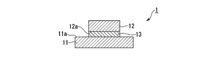
- FIG. 2 is a cross-sectional view schematically illustrating an example of a method for joining metal members according to an embodiment of the present invention.
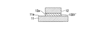
- FIG. 2 is a cross-sectional view schematically illustrating an example of a method for joining metal members according to an embodiment of the present invention.
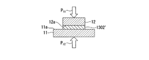
- FIG. 2 is a cross-sectional view schematically illustrating an example of a method for joining metal members according to an embodiment of the present invention.
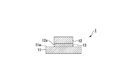
- FIG. 2 is a cross-sectional view schematically illustrating an example of a method for joining metal members according to an embodiment of the present invention.
- FIG. 4 is a cross-sectional view for schematically explaining another example of the method for joining metal members according to one embodiment of the present invention.
- FIG. 4 is a cross-sectional view for schematically explaining another example of the method for joining metal members according to one embodiment of the present invention.
- FIG. 4 is a cross-sectional view for schematically explaining another example of the method for joining metal members according to one embodiment of the present invention.
- FIG. 4 is a cross-sectional view for schematically explaining another example of the method for joining metal members according to one embodiment of the present invention.
- FIG. 10 is a cross-sectional view schematically illustrating still another example of the method for joining metal members according to an embodiment of the present invention.
- FIG. 10 is a cross-sectional view schematically illustrating still another example of the method for joining metal members according to an embodiment of the present invention.
- FIG. 10 is a cross-sectional view schematically illustrating still another example of the method for joining metal members according to an embodiment of the present invention.
- FIG. 10 is a cross-sectional view schematically illustrating still another example of the method for joining metal members according to an embodiment of the present invention.
- FIG. 10 is a cross-sectional view schematically illustrating still another example of the method for joining metal members according to an embodiment of the present invention.
- FIG. 10 is a cross-sectional view schematically illustrating still another example of the method for joining metal members according to an embodiment of the present invention.
- FIG. 10 is a cross-sectional view schematically illustrating still another example of the method for joining metal members according to an embodiment of the present invention.
- FIG. 10 is a cross-sectional view schematically illustrating still another example of the method for joining metal members according to an embodiment of the present invention.
- FIG. 10 is a cross-sectional view schematically illustrating still another example of the method for joining metal members according to an embodiment of the present invention.
- FIG. 10 is a cross-sectional view schematically illustrating still another example of the method for joining metal members according to an embodiment of the present invention.
- FIG. 10 is a cross-sectional view schematically illustrating still another example of the method for joining metal members according to an embodiment of the present invention.
- FIG. 10 is a cross-sectional view schematically illustrating still another example of the method for joining metal members according to an embodiment of the present invention.
- FIG. 10 is a cross-sectional view schematically illustrating still another example of the method for joining metal members according to an embodiment of the present invention.
- FIG. 10 is a cross-sectional view schematically illustrating still another example of the method for joining metal members according to an embodiment of the present invention.
- FIG. 10 is a cross-sectional view schematically illustrating still another example of the method for joining metal members according to an embodiment of the present invention.
- FIG. 10 is a cross-sectional view schematically illustrating still another example of the method for joining metal members according to an embodiment of the present invention.
- FIG. 9 is a cross-sectional view schematically illustrating another example of the joining step in the joining method of the metal member according to the embodiment of the present invention.
- FIG. 9 is a cross-sectional view schematically illustrating another example of the joining step in the joining method of the metal member according to the embodiment of the present invention.
- FIG. 9 is a cross-sectional view schematically illustrating another example of the joining step in the joining method of the metal member according to the embodiment of the present invention.
- FIG. 10 is a cross-sectional view schematically illustrating another example of the joining step in the joining method of the metal member according to the embodiment of the present invention.
- FIG. 9 is a cross-sectional view schematically illustrating another example of the joining step in the joining method of the metal member according to the embodiment of the present invention.
- FIG. 9 is a cross-sectional view schematically illustrating still another example of the joining step in the method for joining metal members according to an embodiment of the present invention.
- FIG. 9 is a cross-sectional view schematically illustrating still another example of the joining step in the method for joining metal members according to an embodiment of the present invention.
- FIG. 9 is a cross-sectional view schematically illustrating still another example of the joining step in the method for joining metal members according to an embodiment of the present invention.
- FIG. 9 is a cross-sectional view schematically illustrating still another example of the joining step in the method for joining metal members according to an embodiment of the present invention.
- FIG. 9 is a cross-sectional view schematically illustrating still another example of the joining step in the method for joining metal members according to an embodiment of the present invention.
- FIG. 9 is a cross-sectional view schematically illustrating still another example of the joining step in the method for joining metal members according to an embodiment of the present invention.
- FIG. 9 is a cross-sectional view schematically illustrating still another example of the joining step in the method for joining metal members according to an embodiment of the present invention.
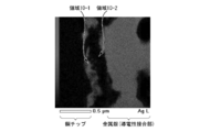
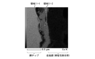
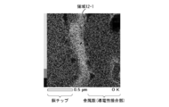
- 4 is image data obtained when the cross section of the joined member made of metal obtained in Example 1 was observed using a transmission electron microscope.
- 5 is imaging data at the time of silver element detection, obtained when the cross section of the metal member joined body obtained in Example 1 was observed by energy dispersive X-ray spectroscopy.
- 4 is imaging data at the time of copper element detection, obtained when the cross section of the metal member joined body obtained in Example 1 was observed by energy dispersive X-ray spectroscopy.
- 4 is imaging data at the time of oxygen element detection, obtained when the cross section of the metal member joined body obtained in Example 1 was observed by energy dispersive X-ray spectroscopy.
- the method for joining metal members is a method for joining metal members, and includes a first metal member (hereinafter simply referred to as “first member” in this specification).
- a first metal member hereinafter simply referred to as “first member” in this specification.
- Silver ink composition adhering to one or both surfaces of a metal second member (which may be simply abbreviated as “second member” in this specification).
- preheating process By baking the heated material while pressing the first member and the second member with a heated material of a silver ink composition interposed therebetween, the first member and the second member are made of metallic silver.
- the silver ink composition may have a group represented by the formula “—COOAg” (hereinafter simply referred to as “silver carboxylate”). ), An amine compound, and formic acid, wherein the silver ink composition is a material for forming metallic silver by firing.
- the first member and the second member have high bonding strength via metallic silver.
- a metal member joined body joined by the above is obtained.
- ⁇ Preheating step> the silver ink composition adhering to the surface of one or both of the first member and the second member is heated at a temperature of 60 ° C. or higher without being solidified. Thereby, a heated product of the silver ink composition is obtained.
- the silver ink composition used in this step is a material for forming metallic silver, and contains the silver carboxylate, the amine compound, and formic acid.
- the silver ink composition before starting heating to obtain the heated product typically contains the silver carboxylate.
- Contains metallic silver particles produced from This is because the formation of metallic silver from the silver carboxylate is promoted by the action of the formic acid.
- the crystallite diameter of the metal silver particles is preferably less than 20 nm, more preferably 19 nm or less, further preferably 17 nm or less.
- the crystallite diameter is less than (or less than) the upper limit, a metal member joined body having higher joining strength can be obtained.
- the lower limit of the crystallite diameter of the metallic silver particles is not particularly limited.
- the crystallite diameter is preferably 3 nm or more from the viewpoint that it is easier to prepare a silver ink composition containing such metallic silver particles.
- the crystallite diameter of the metal silver particles can be appropriately adjusted within a range set by arbitrarily combining any of the above-described upper and lower limits.
- the crystallite diameter of the metal silver particles may be any one of 3 nm to 20 nm, 3 to 19 nm, and 3 to 17 nm. However, these are examples of the crystallite diameter of the metal silver particles.
- the first member is made of metal, and the metal constituting the first member may be any of a single metal and an alloy.
- Preferred examples of the metal include copper, silver, gold, palladium, nickel, and alloys containing one or more selected from the group consisting of copper, silver, gold, palladium, and nickel. .
- the metal is more preferably copper, silver, gold, palladium or nickel, and further preferably copper or silver.
- a member having a metal layer provided on the surface of a metal member may be used as the member including the first member.
- the metal layer can be formed on the surface of the metal member by a known method such as vapor deposition and plating.
- a portion where a silver ink composition for forming a conductive bonding portion described later is attached is a first member.
- the metal layer becomes the first member.
- both the metal member and the metal layer become the first member.
- the metal member is the first member.
- a metal member having such a metal layer on its surface for example, a copper member having a silver layer on its surface is exemplified, but this is only an example.
- a composite of a metal member and a non-metal member may be used as the member including the first member.
- the nonmetallic member include a semiconductor wafer, a semiconductor chip, an organic insulating base, an inorganic insulating base, an organic / inorganic composite insulating base, and the like, and these may be publicly known.
- Examples of the semiconductor wafer or semiconductor chip include a wafer or chip made of a semiconductor such as silicon, silicon carbide, or gallium nitride.
- Examples of the organic insulating substrate include a polytetrafluoroethylene (PTFE) substrate, a polyimide substrate, a liquid crystal polymer substrate, and a cycloolefin polymer substrate.
- Examples of the inorganic insulating substrate include a ceramic substrate and the like.
- the organic / inorganic composite insulating base material is a base material having both an organic material and an inorganic material as constituent materials, and examples thereof include a glass epoxy resin base material.
- the composite regardless of the type of the non-metallic member, for example, at a target portion of the non-metallic member, by vapor deposition, plating, sputtering or printing, etc., to form a metal member, or brazing Alternatively, it can be produced by joining metal members by bonding with an adhesive or the like.
- the metal members those provided on the semiconductor wafer, the semiconductor chip, the organic insulating base material, the inorganic insulating base material, or the organic / inorganic composite insulating base material have mainly been described.
- a metal plate for example, a heat radiating plate not provided on these is also suitable.
- the shape of the first member is not particularly limited.
- the first member has a sheet shape, a plate shape, a prism shape, a pyramid shape, a column shape, a conical shape, a spherical shape, a long spherical shape, and a rod shape.
- the size of the first member is not particularly limited.
- the shape and size of the first member can be appropriately selected according to the use of the first member.
- the length of one side of the first member on the joining surface is 0.01 to 30 mm, 0.02 to 24 mm, and
- the thickness may be any of 0.03 to 18 mm, and the thickness of the first member may be any of 0.01 to 5 mm, 0.02 to 3 mm, and 0.03 to 1.5 mm.
- the first members having these shapes and sizes are suitable, for example, as electrodes forming a circuit.
- the first member is formed such that the area of the bonding surface is equal to the area of the bonding surface calculated from the length of one side described above.
- the size of one member can be adjusted.
- the first member has a plate shape or a rod shape
- any combination of the above-described numerical ranges can be adopted as a combination of the length of one side of the joint surface and the thickness thereof.
- the length of the one side may be 0.01 to 30 mm
- the thickness may be 0.01 to 5 mm
- the length of the one side may be 0.1 to 0.5 mm. 02 to 24 mm
- the thickness may be 0.02 to 3 mm
- the length of one side may be 0.03 to 18 mm
- the thickness may be 0.03 to 1 mm. .5 mm.
- the second member is also made of metal.
- the metal forming the second member include the same metal as the above-described metal forming the first member.
- the shape of the second member may be the same as the shape of the first member.
- the size of the second member may be similar to the size of the first member.
- the second member can also be used as a member including the second member as in the case of the first member.
- the member including the second member can be used in the same manner as the member including the first member described above.
- the first member and the second member may be the same or different from each other.
- the first member and the second member to be joined in the joining step described later may be the same or different from each other in terms of material, shape, and size.
- the first member and the second member are plate-shaped or rod-shaped, and the length of one side of the joint surface of the first member is the same as the length of one side of the joint surface of the second member. May be different from each other, and those each having a length of 0.01 to 30 mm are an example of a preferable combination of the first member and the second member.
- the first member and the second member are plate-shaped or rod-shaped, and the thickness of the first member and the thickness of the second member may be the same or different.
- a combination of the first member and the second member having a diameter of 0.01 to 5 mm is a preferable example.
- Preferred first and second members in the present embodiment include, for example, electrodes constituting a circuit.
- one or both of the first member and the second member are used with a silver ink composition adhered to the surface thereof. That is, in the preheating step, (A1) a combination of the first member having the silver ink composition adhered to the surface thereof and the second member having no silver ink composition adhered to the surface (in the present specification) May be referred to as “combination (A1)”), (A2) a first member having no silver ink composition adhered to its surface, a second member having a silver ink composition adhered to its surface, (In this specification, it may be referred to as “combination (A2)”), or (A3) a first member having a silver ink composition adhered to its surface, and a silver ink composition formed on its surface. A combination of the second member and the attached second member (hereinafter, sometimes referred to as “combination (A3)”) is used.
- the silver ink composition adhering to the surface of the first member and the silver ink composition adhering to the surface of the second member may be the same. And may be different from each other.
- a silver ink composition can be attached to the surface of the first member or the second member by a known method such as a printing method and a coating method.
- a screen printing method for example, a screen printing method, a flexographic printing method, an offset printing method, a dip printing method, an inkjet printing method, a dispenser printing method, a jet dispenser printing method, a gravure printing method, a gravure offset printing method, Pad printing method and the like can be mentioned.
- the coating method for example, a method using various coaters such as a spin coater, an air knife coater, a curtain coater, a die coater, a blade coater, a roll coater, a gate roll coater, a bar coater, a rod coater, and a gravure coater; A method using a coating device such as a slot die; and a spray method.
- various coaters such as a spin coater, an air knife coater, a curtain coater, a die coater, a blade coater, a roll coater, a gate roll coater, a bar coater, a rod coater, and a gravure coater
- a method using a coating device such as a slot die
- a spray method for example, a method using various coaters such as a spin coater, an air knife coater, a curtain coater, a die coater, a blade coater, a roll coater, a gate roll coater, a bar coater, a rod coater
- the cleaning treatment can be performed by a known method, and may be, for example, any of a chemical treatment of the surface with a chemical and a physical treatment by surface processing.
- the drug include acids such as nitric acid, phosphoric acid, sulfuric acid, and hydrochloric acid; and organic solvents such as acetone.
- the chemical treatment with an acid is useful when performing general removal of impurities. When an acid is used, it is preferable to further wash the acid-treated surface of the first member or the second member with water. Chemical treatment with an organic solvent is useful when removing fat-soluble impurities.
- the surface processing include a polishing process using an abrasive such as a file.
- the silver ink composition containing the silver carboxylate, the amine compound, and formic acid is used because it has the following advantages. That is, the silver ink composition is advantageous for increasing the amount of the silver carboxylate in the entire silver ink composition containing the silver carboxylate. In that case, since the silver ink composition has a large content of the component derived from the silver carboxylate (for example, silver carboxylate, metallic silver generated from silver carboxylate, etc.) per unit amount, the first member and the second On the surfaces of the two members, more of the heated object can be formed by one application.
- the silver ink composition has a large content of the component derived from the silver carboxylate (for example, silver carboxylate, metallic silver generated from silver carboxylate, etc.) per unit amount, the first member and the second On the surfaces of the two members, more of the heated object can be formed by one application.
- the silver ink composition has a large viscosity, it is easy to increase the adhesion amount of the silver ink composition on the surfaces of the first member and the second member. Therefore, also in this respect, the silver ink composition can form a larger amount of the heated material in one operation on the surfaces of the first member and the second member. As described above, the silver ink composition is advantageous in that the amount of the heated material formed on the surfaces of the first member and the second member can be easily increased.
- the first member and the second member to which the silver ink composition is attached are made of metal, and a metal oxide is easily generated on the surface by an oxidation reaction.
- a metal oxide is formed into a film or a non-film, not only the resistivity of the metal member joined body increases, but also the bonding strength of the metal member joined body decreases.
- formic acid contained in the silver ink composition has a reducing action, and the silver ink composition itself has a good reducing property. Therefore, the silver ink composition is advantageous in that the amount of metal oxide can be reduced on the surfaces of the first member and the second member.
- the compound having a formyl group has a more active reducing action under basic conditions.
- the silver ink composition is basic under the influence of the compounded amine compound, and the reducing action of formic acid having a formyl group is more activated. Therefore, the silver ink composition is advantageous in that the effect of using the above-described formic acid is higher.
- the amount of the silver ink composition deposited on the surface of the first member or the second member is not particularly limited, and may be appropriately set in consideration of the desired thickness of the conductive joint.
- the thickness of the heated silver ink composition on the surface of the first member or the second member is preferably 100 ⁇ m or more, more preferably 200 ⁇ m or more, and further preferably 250 ⁇ m or more.
- a metal member joined body having higher joining strength can be obtained.
- the upper limit of the thickness of the heated material of the silver ink composition on the surface of the first member or the second member is not particularly limited. In order to avoid an excessive thickness, the thickness of the heating object is preferably 1000 ⁇ m or less.
- the thickness of the heating object can be appropriately adjusted within a range set by arbitrarily combining any of the above-described lower limit and upper limit.
- the thickness of the heated object may be any of 100 to 1000 ⁇ m, 200 to 1000 ⁇ m, and 250 to 1000 ⁇ m. However, these are examples of the thickness of the heating object.
- the heated material of the silver ink composition may be a single layer, may be two or more layers, and when there are two or more layers, the combination and ratio thereof may be determined according to the purpose. Can be adjusted arbitrarily.
- the heated material of the silver ink composition has two or more layers, the total thickness of each layer is preferably set to the above-described preferable thickness of the heated material.
- the amount of the silver ink composition to be applied can be reduced to the target amount by performing the operation of applying the silver ink composition only once. May not be. In this case, it is necessary to repeat the operation of attaching the silver ink composition twice or more.
- the heating product finally obtained may have one layer, but may have two or more layers. Further, for example, depending on the purpose, it may be required to form a conductive bonding portion composed of two or more layers having different compositions. In that case, it is necessary to perform the operation of attaching different types of silver ink compositions twice or more in total. In this case, the heated product finally obtained has two or more layers. In the present embodiment, the heating object having two or more layers can be handled in the same manner as the heating object having one layer regardless of the type.
- the operation of attaching the silver ink composition to one of the first member and the second member is repeated twice or more.
- the silver ink composition adheres to the surface.
- the combination (A3) the combination of the first member having the above-mentioned structure and the second member having the silver ink composition adhered to the surface thereof (that is, the combination (A3))
- the same 2 A conductive joint composed of the above layers can be formed.
- the preheating step the first member to which the silver ink composition has adhered and the second member to which the silver ink composition has adhered both directly to a portion where the silver ink composition has not adhered. Heating is preferred. That is, in the preheating step, when the silver ink composition is attached to the surface of the first member, heating a portion of the first member where the silver ink composition is not attached. Then, the silver ink composition is heated, and when the silver ink composition is attached to the surface of the second member, the portion of the second member where the silver ink composition is not attached is heated. By doing so, it is preferable to heat the silver ink composition. By doing so, the effect of suppressing undesired deterioration of the silver ink composition becomes higher.
- the silver ink composition may be, for example, a known heat source such as heating by an electric furnace, heating by a thermal head, heating by far-infrared irradiation, heating by spraying a high-temperature gas, heating by high-frequency irradiation, and dielectric heating. Depending on the method, heating can be performed.
- a known heat source such as heating by an electric furnace, heating by a thermal head, heating by far-infrared irradiation, heating by spraying a high-temperature gas, heating by high-frequency irradiation, and dielectric heating.
- heating can be performed.
- the silver ink composition adhering to the surface of the first member and the silver ink adhering to the surface of the second member The composition is heated at a temperature of at least 60 ° C. However, at this time, the silver ink composition to be heated is not solidified. In this step, the heated material of the silver ink composition obtained without solidification maintains fluidity.
- the temperature at the start of heating the silver ink composition may be, for example, room temperature.
- “normal temperature” means a temperature at which cooling or heating is not particularly performed, that is, a normal temperature, for example, a temperature of 15 to 25 ° C. or the like.
- the heating temperature of the silver ink composition in the preheating step may be, for example, any of 70 ° C or higher, 80 ° C or higher, and 90 ° C or higher.
- the upper limit of the heating temperature of the silver ink composition in the preheating step is not particularly limited.
- the heating temperature is preferably 120 ° C. or less from the viewpoint that the solidification of the silver ink composition can be easily avoided.
- the heating temperature of the silver ink composition in the preheating step can be appropriately adjusted within a range set by arbitrarily combining any of the above-described lower limits and upper limits.
- the heating temperature may be any of 60 to 120 ° C, 70 to 120 ° C, 80 ° C to 120 ° C, and 90 to 120 ° C.
- these are examples of the heating temperature.
- the heating rate of the silver ink composition during heating is not particularly limited, but is preferably 5 to 50 ° C./min, more preferably 5 to 30 ° C./min. More preferably, it is ⁇ 16 ° C./min.
- the heating time of the silver ink composition is not particularly limited, but is preferably 1 minute to 12 hours, more preferably 2 minutes to 6 hours, and more preferably 4 minutes to 1 hour. Is more preferable.
- the preheating step may be performed under any of normal pressure, reduced pressure, and increased pressure. Further, the preheating step may be performed, for example, in any of an air atmosphere and an inert gas atmosphere.
- the inert gas include a nitrogen gas, an argon gas, and a helium gas.
- the preheating step is preferably performed under reduced pressure or an inert gas atmosphere when the preheating step is performed under conditions that can suppress the oxidation reaction of the first member, the second member, the silver ink composition, and the heated object.
- the preheating step is preferably performed, for example, in an inert gas atmosphere from the viewpoint that the effect of suppressing the oxidation reaction is high, and is preferably performed under reduced pressure from the viewpoint of low cost.
- the temperature of the silver ink composition may be consistently increased (in other words, neither constant nor reduction may be performed) by the end of the preheating step.
- a fixed time may be provided, or a time for decreasing the time may be provided.
- the temperature of the silver ink composition must be raised or kept constant from the start to the end of the preheating step. (In other words, it is not reduced at all).
- the time for maintaining the temperature of the silver ink composition for a certain time is preferably 0.5 to 10 minutes, more preferably 0.5 to 6 minutes, and 0.5 to 3 minutes. Is more preferable.
- the preheating step bubbling is typically observed in the silver ink composition until a heated material of the silver ink composition is obtained. This is because the reaction of the components proceeds in the silver ink composition, gas is generated, and the gas escapes. Typically, by the end of the process, the bubbling has disappeared and gas evolution has almost or completely stopped. Since the bubbling of the silver ink composition occurs as described above, the mass of the heated silver ink composition at the end of this step is smaller than the mass of the silver ink composition at the start of this step. That is, in this step, a decrease in the mass of the silver ink composition is recognized.
- a preheating step may be performed (in this specification, this may be referred to as a “preheating method (B2)”).
- the preheating method (B1) or (B3) is preferably employed, and the preheating method (B1) is more preferably employed, in terms of obtaining a metal member joined body having a higher joining strength. .
- the combination (A1) When the combination (A1) is selected in the preheating step, the silver ink composition before heating, the silver ink composition during heating, or the silver ink composition after heating attached to the surface of the first member The second member is brought into contact with (that is, the heated object).
- the combination (A2) is selected in the preheating step, the silver ink composition before heating, the silver ink composition during heating, or the silver ink composition after heating attached to the surface of the second member
- the first member is brought into contact with (ie, the heated object).
- the silver ink composition adhering to the first member or the second member forms a conductive joint that joins the first member and the second member in a later step.
- the bonding strength of the conductive bonding portion is significantly increased.
- the reason for such an excellent effect is not clear, but by heating the silver ink composition without solidifying, unlike the case of solidifying, the obtained heated material has fluidity. It is presumed that this is because the adhesion between the heated object and the first member and the adhesion between the heated object and the second member are improved.
- the heated product obtained in the preheating step does not typically have a luster characteristic of metallic silver, and is, for example, dark green. Due to such external characteristics, the heated material does not use high-purity metallic silver as a main constituent material.
- the first member and the second member are pressed against each other with a heated material of the silver ink composition interposed therebetween, and the heated material is baked.
- One member and the second member are joined by metallic silver.
- the silver ink composition is a material for forming metallic silver, and in this step, is solidified by baking to finally form metallic silver, and joins the first member and the second member.
- a pressure in a direction from the first member to the second member is applied to a composite in which the first member, the heated object, and the second member are stacked in this order, and the second member By applying one or both of the pressure in the direction from the first member to the first member, the first member and the second member can be press-bonded.
- pressure When pressure is applied to the composite in the direction from the first member to the second member, it is preferable to apply the pressure in this direction while the second member is fixed.
- pressure When pressure is applied to the composite in a direction from the second member to the first member, the pressure is preferably applied in this direction while the first member is fixed.
- the above-described two directions of pressure may be applied by a known method.
- one of the surfaces of the first member and the second member is vertically downward, and the composite is fixed on a horizontal plane
- pressure can be applied to the composite from only one direction.
- a case has been described where pressure is applied to one of the first member and the second member by placing a weight, but pressure may be applied by another pressing means.
- the composite is arranged with the surfaces of the first member and the second member facing in the vertical direction has been described, but not in the vertical direction but in other directions including the horizontal direction. , The composite may be arranged.
- a pressure (hereinafter, may be abbreviated as “pressing pressure” in this specification) when the first member and the second member are press-bonded with the heating object interposed therebetween is not particularly limited. , 0.2 MPa or more, more preferably 0.4 MPa or more, even more preferably 0.6 MPa or more.
- pressing pressure is equal to or higher than the lower limit, a metal member joined body having higher joining strength can be obtained.
- the upper limit value of the pressure is not particularly limited. It is preferable that the pressing pressure is 3 MPa or less in that the pressing can be performed more easily.
- the pressing pressure can be appropriately adjusted within a range set by arbitrarily combining any of the above-described lower limit and upper limit.
- the pressing pressure may be any one of 0.2 to 3 MPa, 0.4 to 3 MPa, and 0.6 to 3 MPa.
- these are examples of the above-mentioned compression pressure.
- the pressing pressure may or may not be constant from the start of pressing to the end of pressing.
- the pressing pressure may be increased consistently (in other words, it is not necessary to perform both the change and the reduction), and a time period during which the pressure is not changed is provided.
- a period for lowering the temperature may be provided.
- the pressure is always increased or not changed (in other words, not reduced at all).
- metallic silver is formed by baking the heated object.
- the heating of the heated object in the joining step can be performed by further heating the heated object.
- the heating at this time can be performed in the same manner as the heating performed on the silver ink composition in the preheating step.
- the temperature at the start of firing of the heated material may be lower than the temperature at the end of the preheating step, such as room temperature, but may be equal to or higher than the temperature at the end of the preheating step. preferable.
- the firing temperature of the heated product in the bonding step may be, for example, any of 170 ° C or higher, 220 ° C or higher, and 270 ° C or higher.
- the upper limit of the firing temperature of the heated material in the bonding step is not particularly limited.
- the firing temperature is preferably 350 ° C. or lower, more preferably 320 ° C. or lower, from the viewpoint of shortening the process time and avoiding an excessively high temperature.
- the reason why the firing temperature can be relatively low is that the silver ink composition uses a relatively limited range of components.
- the firing temperature of the heated product in the bonding step can be appropriately adjusted within a range set by arbitrarily combining any one of the above-described lower limits and any one of the upper limits.
- the firing temperature may be any of 170-350 ° C, 220-350 ° C, and 270-350 ° C.
- the firing temperature may be any of 170 to 320 ° C, 220 to 320 ° C, and 270 to 320 ° C.
- the heating rate of the heated material during firing is not particularly limited, but is preferably 5 to 50 ° C./min, more preferably 5 to 45 ° C./min, and 5 to 40 ° C. / Min is more preferable.
- the baking time of the heated product is not particularly limited, but is preferably 1 minute to 24 hours, more preferably 5 minutes to 12 hours, and further preferably 10 minutes to 2 hours. preferable.
- the firing temperature of the heated object may be increased consistently (in other words, both constant and lowering may not be performed) by the end thereof, A fixed time may be provided, or a time for lowering the time may be provided. Above all, during the period from the start to the end of the joining step, it is preferable that the firing temperature of the heated object is always raised or kept constant (in other words, not lowered at all). After the firing temperature of the heated material is consistently increased from the start, the maximum temperature reached there may be maintained for a certain period of time until the end of the bonding process. In that case, the time for maintaining the firing temperature of the heated product for a certain period of time is preferably 5 to 60 minutes, more preferably 10 to 50 minutes, and even more preferably 15 to 40 minutes.
- the joining step may be performed under any of normal pressure, reduced pressure, and increased pressure. Further, the bonding step may be performed, for example, in any of an air atmosphere and an inert gas atmosphere. Examples of the inert gas include a nitrogen gas, an argon gas, and a helium gas.
- the bonding step is performed under conditions that can suppress the oxidation reaction of the first member, the second member, and the fired product (that is, metallic silver), it is preferable to perform the bonding process under reduced pressure or in an inert gas atmosphere.
- the bonding step is preferably performed in an inert gas atmosphere, for example, from the viewpoint that the effect of suppressing the oxidation reaction is high, and is preferably performed under reduced pressure from the viewpoint of low cost.
- the thickness of the conductive bonding portion (in other words, metallic silver) formed by baking the heated material is preferably 10 ⁇ m or more, more preferably 20 ⁇ m or more, and even more preferably 25 ⁇ m or more. .
- the thickness of the conductive bonding portion is equal to or more than the lower limit, the bonding strength of the metal member bonded body is further increased. Further, a conductive joint having a thickness of 20 ⁇ m or more is easier to form.
- “the thickness of the conductive joint” means “the thickness of the conductive joint in the joining direction of the first member and the second member”.
- the upper limit of the thickness of the conductive joint is not particularly limited. From the viewpoint of avoiding an excessive thickness, the thickness of the conductive bonding portion is preferably 100 ⁇ m or less.
- the thickness of the conductive bonding portion can be appropriately adjusted within a range set by arbitrarily combining any of the above-described lower limit and upper limit.
- the thickness of the conductive joint may be any of 10 to 100 ⁇ m, 20 to 100 ⁇ m, and 25 to 100 ⁇ m. However, these are examples of the thickness of the conductive joint.
- the thickness of the conductive joint is determined, for example, by the thickness of the heated object before firing.
- the thickness of the conductive joint is preferably 4 to 16%, more preferably 6 to 14%, and still more preferably 8 to 12% with respect to the thickness of the heated object before firing. It is possible. However, these are examples of the relationship between the thickness of the conductive bonding portion and the thickness of the heated object before firing.
- the firing of the heated object may be started after (C1) the pressing of the first member and the second member is started (in the present specification, the “pressure bonding firing method (C1)”). ), And (C2) after the firing of the heated material is started, the pressure bonding of the first member and the second member may be started (in the present specification, the “pressure bonding firing method”). (C2)), and (C3) the pressing of the first member and the second member and the firing of the heated material may be started simultaneously (in the present specification, the “press bonding”).
- the firing method (C3) may be referred to as "), and the timings of the above-mentioned press bonding and the start of firing can be arbitrarily selected.
- the compression sintering method (C1) or (C3) it is preferable to employ the compression sintering method (C1) or (C3), and more preferably to employ the compression sintering method (C1), from the viewpoint of obtaining a metal member joined body having a higher bonding strength. .
- the bonding strength of the conductive bonding portion is significantly increased by the pressure bonding of the first member and the second member with the heated object interposed. Unlike the conventional case, it can be said that such an increase in bonding strength in a conductive bonding portion containing no resin component such as a binder is completely surprising. The reason for such an excellent effect is not clear, but the laminated structure of the first member, the heated object being fired, and the second member is pressed together in the thickness direction thereof. This is presumed to be due to the fact that the volume of the voids decreases and the density increases in the heated material during firing, and as a result, the strength of the fired product (conductive joint) improves.
- the strength of the conductive joint of the metal member joined body obtained in the present embodiment can be evaluated, for example, by a measured value of die shear strength.
- the die shear strength can be measured in accordance with JIS C62137-1-2: 2010 (lateral shear strength test, IEC 62137-1-2: 2007). That is, in the metal member joined body, one of the first member and the second member joined by the conductive joint is fixed, and the other is the first member, the conductive joint and the second member. Is applied in a direction perpendicular to the stacking direction (in other words, a direction parallel to the stacking surfaces), and the stacked structure of these (the first member, the conductive joint and the second member) is broken. The above-mentioned force applied at the time of the application is adopted as the die shear strength.
- the die shear strength of the joined metal member is preferably 15 MPa or more, and may be, for example, any of 22.5 MPa or more, 27.5 MPa or more, and 32.5 MPa or more.
- the upper limit of the die shear strength of the joined metal member is not particularly limited.
- the die shear strength is preferably 50 MPa or less from the viewpoint of facilitating the production of the joined metal member.
- the die shear strength can be appropriately adjusted within a range set by arbitrarily combining any of the lower limit and the upper limit described above.
- the die shear strength may be any of 15 to 50 MPa, 22.5 to 50 MPa, 27.5 to 50 MPa, and 32.5 to 50 MPa.
- these are examples of the die shear strength.
- the method for joining metal members of the present embodiment may have other steps that do not correspond to any of the preheating step and the joining step, as long as the effects of the present invention are not impaired.
- the other steps are not particularly limited and can be arbitrarily selected according to the purpose.
- the timing at which the other steps are performed can be arbitrarily selected depending on the purpose, and may be, for example, any of before the preheating step, between the preheating step and the bonding step, and after the bonding step. .
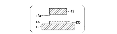
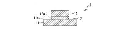
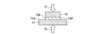
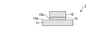
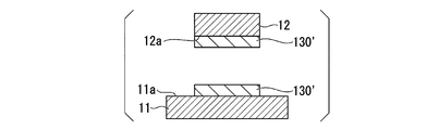
- FIG. 1A, FIG. 1B, FIG. 1C, and FIG. 1D are cross-sectional views for schematically explaining an example of a method for joining metal members according to an embodiment of the present invention.
- the main portions may be enlarged, and the dimensional ratios and the like of the respective components may be the same as actual ones. Is not always the case.
- the same components as those shown in the already described drawings are denoted by the same reference numerals as those in the already described drawings, and detailed description thereof will be omitted.
- FIGS. 1A to 1D show a method of joining metal members when the combination (A1) and the preheating method (B1) are selected (in this specification, “joining method (1-1)
- FIG. 2 is a cross-sectional view for schematically explaining the above-mentioned “)”. That is, in the preheating step of the bonding method (1-1), as shown in FIG. 1A, the first member 11 having the silver ink composition 130 adhered to the surface and the silver ink composition adhered to the surface. And a second member 12 not used. The silver ink composition 130 is attached to one surface (hereinafter, sometimes referred to as “first surface”) 11 a of the first member 11.
- the silver ink composition 130 adhering to the first surface 11a of the first member 11 is heated at a temperature of 60 ° C. or higher without being solidified. By doing so, as shown in FIG. 1B, a heated product 130 ′ of the silver ink composition 130 is obtained.
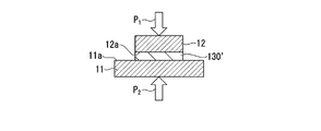
- the first member 11 and the second member 12 are pressed against each other with the heated material 130 ′ of the silver ink composition interposed therebetween. Then, the heating object 130 'is fired. At this time, the first member 11, and the heated 130 ', the force applied to crimp the second member 12, the laminated structure of, and either or both of the force P 1 and the force P 2 be able to. At this time, a surface (sometimes referred to as a “first surface”) 12a of the second member 12 on the first member 11 side comes into contact with the heating object 130 ′.
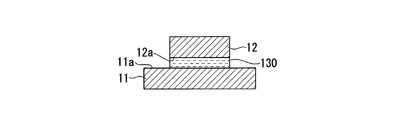
- the first member 11 and the second member 12 are made of metal joined together via metallic silver (in other words, a conductive joint) 13.
- the member joined body 1 is obtained.
- FIGS. 2A to 2D are cross-sectional views schematically illustrating another example of the method for joining metal members according to an embodiment of the present invention. More specifically, FIGS. 2A to 2D show a method of joining metal members when the combination (A2) and the preheating method (B1) are selected (in this specification, “joining method (2-1) FIG. 2) is a cross-sectional view for schematically explaining the above-mentioned “)”. That is, in the preheating step of the bonding method (2-1), as shown in FIG. 2A, the first member 11 having no silver ink composition adhered to the surface and the silver ink composition 130 adhered to the surface. And the second member 12 that is used. The silver ink composition 130 is attached to the first surface 12a of the second member 12.
- the silver ink composition 130 adhered to the first surface 12a of the second member 12 is heated at a temperature of 60 ° C. or higher without being solidified. As a result, as shown in FIG. 2B, a heated product 130 ′ of the silver ink composition 130 is obtained.
- the joining step of the joining method (2-1) as shown in FIG. 2C, the first member 11 and the second member 12 are pressed against each other with the heated material 130 ′ of the silver ink composition interposed therebetween. Then, the heating object 130 'is fired. At this time, the surface of the first member 11 on the second member 12 side, that is, the first surface 11a comes into contact with the heating object 130 '.
- the joining method (1-1) described with reference to FIGS. 1A to 1D is used. ) Can be performed in the same manner as in the case of).
- the first member 11 and the second member 12 are made of metal joined together via metallic silver (in other words, a conductive joint) 13.
- the member joined body 1 is obtained.
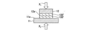
- FIGS. 3A to 3D show a method of joining metal members when the combination (A3) and the preheating method (B1) are selected (in this specification, “joining method (3-1) FIG. 2) is a cross-sectional view for schematically explaining the above-mentioned “)”. That is, in the preheating step of the bonding method (3-1), as shown in FIG. 3A, the first member 11 having the silver ink composition 130 adhered to the surface, and the silver ink composition 130 being adhered to the surface. And the second member 12 is used. The silver ink composition 130 is attached to both the first surface 11a of the first member 11 and the first surface 12a of the second member 12. These silver ink compositions 130, 130 may be the same or different.
- a heated product 130 ′ of the silver ink composition 130 is obtained.
- the bonding step of the bonding method (3-1) as shown in FIG. 3C, the first member 11 and the second member 11 are interposed with the two layers of the heated materials 130 ′ and 130 ′ of the silver ink composition. 12 while being pressed against each other, the heating objects 130 'and 130' are fired. At this time, the heating object 130 'on the first surface 11a of the first member 11 comes into contact with the heating object 130' on the first surface 12a of the second member 12. In this step, after forming such a laminated structure of the first member 11, the two-layered heating object 130 ', and the second member 12, the object to be crimped is this laminated structure. Except for this point, the bonding can be performed by the same method as the bonding method (1-1) described with reference to FIGS. 1A to 1D.
- the first member 11 and the second member 12 are formed of two layers of metallic silver (layer) 13, in other words, the conductive bonding portion 23, Thus, a metal member joined body 2 joined through the steps is obtained.
- the conductive bonding portion 23 in the metal member bonded body 2 is formed of two layers.
- the silver ink composition 130 initially attached to the first member 11 and the silver ink composition 130 originally attached to the second member 12 are of different types.
- the conductive bonding portion 23 is formed of such two layers.
- the conductive bonding portion 23 may be formed of two layers as described above, or may be a single-layer conductive bonding portion (for example, a conductive bonding portion similar to the conductive bonding portion 13 shown in FIGS. 1D and 2D). Sometimes it becomes.
- FIGS. 4A, 4B, 4C, and 4D show a method of joining metal members when the combination (A1) and the preheating method (B2) are selected.
- FIG. 2) is a cross-sectional view for schematically explaining the above. That is, in the preheating step of the bonding method (1-2), as in the case of the bonding method (1-1), as shown in FIG. 4A, the first ink in which the silver ink composition 130 is adhered to the surface is used. A combination of the member 11 and the second member 12 having no silver ink composition adhered to the surface is used.
- the first member 11 is then interposed via the silver ink composition 130 attached to the first surface 11a of the first member 11. And the second member 12 are brought into contact. Then, after the first member 11, the silver ink composition 130, and the second member 12 are stacked as described above, the silver ink composition 130 is heated without being solidified at a temperature of 60 ° C. or more, thereby obtaining FIG. 4C. As shown, a heated product 130 'of the silver ink composition 130 is obtained. As a result, a laminated structure of the first member 11, the heating object 130 ', and the second member 12 in a state similar to that shown in FIG. 1C is obtained.
- the heated material 130 ′ of the silver ink composition is interposed in the same manner as in the case of the bonding method (1-1). While the first member 11 and the second member 12 are pressed against each other, the heating object 130 ′ is fired.
- the first member 11 and the second member 12 are made of metal which is joined via metallic silver (in other words, a conductive joint) 13.
- the member joined body 1 is obtained.
- FIGS. 5A, 5B, 5C, 5D, 5E, and 5F show a method of joining metal members when the combination (A1) and the preheating method (B3) are selected.
- FIG. 4 is a cross-sectional view schematically illustrating a bonding method (1-3) ”). That is, in the pre-heating step of the bonding method (1-3), as in the case of the bonding method (1-1), as shown in FIG. A combination of the member 11 and the second member 12 having no silver ink composition adhered to the surface is used.
- the silver ink composition 130 adhered to the first surface 11a of the first member 11 is not solidified at a temperature of 60 ° C. or more. Then, as shown in FIG. 5B, heating is started.
- reference numeral 1301 is given to the silver ink composition in the middle of heating before it becomes the heated product 130 '.
- the first member 11 and the second member 12 are interposed in the middle of this step via the silver ink composition 1301 being heated.
- the temperature of the silver ink composition 1301 during heating at the time of such contact may be lower than 60 ° C. or may be 60 ° C. or higher.
- the silver ink composition 1301 being heated which is thus adhered to the first member 11 and the second member 12, is further heated to 60 ° C. or more.
- a heated product 130 'of the silver ink composition 130 is obtained as shown in FIG. 5D.
- the heated material 130 'of the silver ink composition is interposed in the same manner as in the case of the joining method (1-1). While the first member 11 and the second member 12 are pressed against each other, the heating object 130 ′ is fired.
- the first member 11 and the second member 12 are made of a metal joined via metal silver (in other words, a conductive joint) 13.
- the member joined body 1 is obtained.
- the silver ink in the joining step is used.
- the timing relationship between the start of pressure bonding of the first member and the second member with the interposition of the heated material of the composition and the timing of the start of firing of the heated material is not specifically described. .
- these contexts can be arbitrarily selected as described above as the press-bonding firing methods (C1) to (C3).
- FIGS. 6A, 6B, 6C, and 6D show a method of joining metal members when a combination (A1), a preheating method (B1), and a pressure bonding and firing method (C1) are selected.
- FIG. 2 is a cross-sectional view for schematically explaining a joining step in a “joining method (1-1-1)” in some cases).
- FIGS. 7A, 7B, 7C, and 7D illustrate a method of joining metal members when a combination (A1), a preheating method (B1), and a pressure bonding firing method (C2) are selected.
- FIG. 2 is a cross-sectional view for schematically explaining a joining step in a “joining method (1-1-2)” in some cases).
- FIGS. 8A, 8B, and 8C illustrate a method of joining metal members (in this specification, a combination (A1), a preheating method (B1), and a pressure bonding firing method (C3)).
- FIG. 4 is a cross-sectional view for schematically explaining a joining step in the “joining method (1-1-3)”).
- the firing of the heating object 130 ′ and the pressing of the laminated structure are simultaneously started.
- a reference numeral P 11 and code P 21 with respect to the firing start the heating of, and reference numeral 1302 '.
- one first member and one second member may be joined with two or more metallic silver (conductive joints).
- one first member and two or more second members may be joined with one metal silver (conductive joint).
- two or more second members may be all the same, may be all different, or may be partially different.
- one first member and two or more second members may be joined with two or more metallic silver (conductive joints).
- the number of second members and the number of metallic silver (conductive joints) may be the same or different.
- two or more second members may be all the same, may be all different, or may be partially different.
- the number of the first members and the number of the second members may be reversed.
- the silver ink composition used in the present embodiment will be described in detail.
- the silver ink composition contains the silver carboxylate, the amine compound, and formic acid.
- the silver ink composition preferably does not contain a resin component such as a binder, and more preferably has the silver carboxylate uniformly dispersed at the time of its compounding.
- the silver carboxylate By using the silver carboxylate, metallic silver is generated from this, and a conductive joint containing the metallic silver as a main component is formed.
- the conductive joint in this case, preferably, by not using the resin component, it is possible to sufficiently increase the proportion of metallic silver to such an extent that the conductive joint can be regarded as apparently composed only of metallic silver. it can.
- the ratio of the total mass of metallic silver in the conductive joint to the total mass of the conductive joint is, for example, any one of 97% by mass or more, 98% by mass or more, and 99% by mass or more. It is possible.
- the upper limit of the ratio is, for example, 100% by mass, 99.9% by mass, 99.8% by mass, 99.7% by mass, 99.6% by mass, 99.5% by mass, 99.4% by mass, 99% by mass. 0.3%, 99.2% and 99.1% by weight, but these are only examples.
- the silver carboxylate is a silver salt of a carboxylic acid, and has a group represented by the formula “—COOAg”.
- the silver carboxylate is not particularly limited as long as it has a group represented by the formula “—COOAg”.
- the number of groups represented by the formula “—COOAg” in one silver carboxylate molecule may be only one, or may be two or more.
- the position of the group represented by the formula “—COOAg” in the silver carboxylate is not particularly limited.
- the silver carboxylate may be used alone, or two or more kinds may be used in combination. When two or more kinds are used in combination, their combination and ratio may be arbitrarily determined. Can be adjusted.
- the silver carboxylate is represented by silver ⁇ -ketocarboxylate represented by the following general formula (1) (hereinafter sometimes abbreviated as “silver ⁇ -ketocarboxylate (1)”) and the following general formula (4). It is preferable to use one or more selected from the group consisting of silver carboxylate (hereinafter sometimes abbreviated as “silver carboxylate (4)”).
- the term “silver carboxylate” is not limited to “silver ⁇ -ketocarboxylate (1)” and “silver carboxylate (4)” unless otherwise specified. Inclusively, it means “silver carboxylate having a group represented by the formula“ —COOAg ””.
- Silver ⁇ -ketocarboxylate (1) is represented by the general formula (1).
- the aliphatic hydrocarbon group having 1 to 20 carbon atoms in R may be any of linear, branched and cyclic (aliphatic cyclic group). When it is cyclic, it may be monocyclic or polycyclic. Any of them may be used. Further, the aliphatic hydrocarbon group may be any of a saturated aliphatic hydrocarbon group and an unsaturated aliphatic hydrocarbon group. The aliphatic hydrocarbon group preferably has 1 to 10 carbon atoms, and more preferably 1 to 6 carbon atoms. Preferred examples of the aliphatic hydrocarbon group for R include an alkyl group, an alkenyl group, and an alkynyl group.
- Examples of the linear or branched alkyl group for R include a methyl group, an ethyl group, an n-propyl group, an isopropyl group, an n-butyl group, an isobutyl group, a sec-butyl group, a tert-butyl group, n-pentyl, isopentyl, neopentyl, tert-pentyl, 1-methylbutyl, 2-methylbutyl, n-hexyl, 1-methylpentyl, 2-methylpentyl, 3-methylpentyl, 4 -Methylpentyl, 1,1-dimethylbutyl, 2,2-dimethylbutyl, 3,3-dimethylbutyl, 2,3-dimethylbutyl, 1-ethylbutyl, 2-ethylbutyl, 3-ethylbutyl Group, 1-ethyl-1-methylpropyl group, n-heptyl
- Examples of the cyclic alkyl group for R include, for example, cyclopropyl group, cyclobutyl group, cyclopentyl group, cyclohexyl group, cycloheptyl group, cyclooctyl group, cyclononyl group, cyclodecyl group, norbornyl group, isobornyl group, 1-adamantyl group, Examples thereof include a 2-adamantyl group and a tricyclodecyl group.
- alkynyl group for R examples include groups in which one single bond (CC) between carbon atoms of the alkyl group for R is replaced with a triple bond (C ⁇ C).
- alkynyl groups include an ethynyl group (—C ⁇ CH) and a propargyl group (—CH 2 —C ⁇ CH).
- one or more hydrogen atoms may be substituted with a substituent.
- Preferred examples of the substituent include a fluorine atom, a chlorine atom, and a bromine atom.
- the number and position of the substituent are not particularly limited. When the number of the substituents is plural, these plural substituents may be the same or different. That is, all the substituents may be the same, all the substituents may be different, or only some of the substituents may be different.
- the phenyl group for R may have one or more hydrogen atoms substituted with a substituent.
- Preferred examples of the substituent include a saturated or unsaturated monovalent aliphatic hydrocarbon group having 1 to 16 carbon atoms, a monovalent group in which the aliphatic hydrocarbon group is bonded to an oxygen atom, and fluorine. Atom, chlorine atom, bromine atom, hydroxyl group (—OH), cyano group (—C ⁇ N), phenoxy group (—O—C 6 H 5 ) and the like.
- the number and position of the substituent are not particularly limited. When the number of the substituents is plural, these plural substituents may be the same or different.
- Examples of the aliphatic hydrocarbon group which is a substituent include those similar to the aforementioned aliphatic hydrocarbon group for R except that the aliphatic hydrocarbon group has 1 to 16 carbon atoms.
- R 1 in R is an aliphatic hydrocarbon group having 1 to 19 carbon atoms or a phenyl group (C 6 H 5 —).
- the aliphatic hydrocarbon group for R 1 is, for example, the same as the above-mentioned aliphatic hydrocarbon group for R except that it has 1 to 19 carbon atoms.
- R 2 in R is an aliphatic hydrocarbon group having 1 to 20 carbon atoms, for example, the same as the above-mentioned aliphatic hydrocarbon group for R.
- R 3 in R is an aliphatic hydrocarbon group having 1 to 16 carbon atoms.
- the aliphatic hydrocarbon group for R 3 is, for example, the same as the above-mentioned aliphatic hydrocarbon group for R except that it has 1 to 16 carbon atoms.
- R 4 and R 5 in R are each independently an aliphatic hydrocarbon group having 1 to 18 carbon atoms. That is, R 4 and R 5 may be the same or different from each other, and the aliphatic hydrocarbon group in R 4 and R 5 is, for example, the same as the above in R except that the carbon number is 1 to 18.
- R 6 in R is an aliphatic hydrocarbon group having 1 to 19 carbon atoms, a hydroxyl group or a group represented by the formula “AgO—”.
- the aliphatic hydrocarbon group for R 6 is, for example, the same as the above-mentioned aliphatic hydrocarbon group for R except that it has 1 to 19 carbon atoms.
- R 6 is preferably a linear or branched alkyl group, a hydroxyl group, or a group represented by the formula “AgO—”.
- halogen atom for X 1 examples include a fluorine atom, a chlorine atom, a bromine atom, and an iodine atom.
- Phenyl and benzyl groups in X 1 is one or more hydrogen atoms may be substituted with a substituent.
- Preferred examples of the substituent include a halogen atom (a fluorine atom, a chlorine atom, a bromine atom, and an iodine atom) and a nitro group (—NO 2 ).
- the number and position of the substituent are not particularly limited. When the number of the substituents is plural, these plural substituents may be the same or different.
- R 7 in X 1 represents an aliphatic hydrocarbon group having 1 to 10 carbon atoms, a thienyl group (C 4 H 3 S—), a phenyl group in which one or more hydrogen atoms may be substituted with a substituent, A diphenyl group (biphenyl group, C 6 H 5 —C 6 H 4 —);
- the aliphatic hydrocarbon group for R 7 is, for example, the same as the above-mentioned aliphatic hydrocarbon group for R except that it has 1 to 10 carbon atoms.
- Examples of the substituent of the phenyl group and the diphenyl group in R 7 include a halogen atom (a fluorine atom, a chlorine atom, a bromine atom, and an iodine atom).
- a halogen atom a fluorine atom, a chlorine atom, a bromine atom, and an iodine atom.
- the number and position of the substituent are not particularly limited. When the number of the substituents is plural, these plural substituents may be the same or different.
- R 7 is a thienyl group or a diphenyl group, the bonding position of these groups with the adjacent group or atom (oxygen atom, sulfur atom, carbonyl group, carbonyloxy group) in X 1 is not particularly limited.
- the thienyl group may be either a 2-thienyl group or a 3-thienyl group.
- two X 1 may be bonded as one group via a double bond to a carbon atom sandwiched between two carbonyl groups.
- a conductor metallic silver formed by using silver ⁇ -ketocarboxylate (1) and subjecting to a solidification treatment such as a drying treatment or a heating (firing) treatment of a silver ink composition
- concentration of the remaining raw materials and impurities is reduced. It can be further reduced.
- the conductor for example, as the amount of raw materials and impurities is smaller, for example, the formed metal silver contacts better, conduction is facilitated, and the resistivity decreases.
- the silver ⁇ -ketocarboxylate (1) is decomposed at a low temperature of preferably 60 to 210 ° C., more preferably 60 to 200 ° C. without using a reducing agent known in the art, as described later, Metallic silver can be formed.
- the silver ⁇ -ketocarboxylate (1) is decomposed at lower temperature to form metallic silver when used in combination with a reducing agent.
- one kind of silver ⁇ -ketocarboxylate (1) may be used alone, or two or more kinds may be used in combination. , Can be adjusted arbitrarily.
- the silver carboxylate (4) is represented by the general formula (4).
- the aliphatic hydrocarbon group for R 8 is the same as the aliphatic hydrocarbon group for R, except that the aliphatic hydrocarbon group has 1 to 19 carbon atoms. However, the aliphatic hydrocarbon group for R 8 preferably has 1 to 15 carbon atoms, and more preferably 1 to 10 carbon atoms.
- the aliphatic hydrocarbon group for R 8 has a methylene group (—CH 2 —)
- one or more methylene groups may be substituted with a carbonyl group.
- the number and position of the methylene groups that may be substituted with a carbonyl group are not particularly limited, and all methylene groups may be substituted with a carbonyl group.
- the “methylene group” means not only a group represented by a single formula “—CH 2 —” but also one of an alkylene group in which a plurality of groups represented by the formula “—CH 2 —” are linked. And a group represented by the formula “—CH 2 —”.
- silver carboxylate (4) When silver carboxylate (4) was used, it was formed by solidification such as drying or heating (firing) of the silver ink composition, as in the case of using silver ⁇ -ketocarboxylate (1). In the conductor (metallic silver), the concentration of remaining raw materials and impurities can be further reduced. The silver carboxylate (4) is decomposed at a lower temperature to form metallic silver when used in combination with a reducing agent.
- one kind of silver carboxylate (4) may be used alone, or two or more kinds may be used in combination. When two or more kinds are used in combination, their combination and ratio are optional. Can be adjusted.
- the silver carboxylate is preferably silver ⁇ -ketocarboxylate (1).
- silver 2-methylacetoacetate, silver acetoacetate, silver isobutyrylacetate and silver pivaloylacetate are excellent in compatibility with nitrogen-containing compounds (among others, amine compounds) described later. It is particularly suitable for increasing the concentration of the silver ink composition.
- the ratio of the total mass of silver derived from the silver carboxylate in the silver ink composition to the total mass of the silver ink composition is preferably 5% by mass or more, more preferably 8% by mass or more. .
- the formed conductive layer has better quality.
- the upper limit of the ratio is not particularly limited as long as the effects of the present invention are not impaired, but is preferably 25% by mass in consideration of the handling properties of the silver ink composition.
- ⁇ silver derived from silver carboxylate '' is synonymous with silver in silver carboxylate blended at the time of manufacturing the silver ink composition, unless otherwise specified, and continues after blending. Includes all of silver that constitutes silver carboxylate, silver in the decomposed product generated by decomposition of silver carboxylate after blending, and silver itself (metallic silver) generated by decomposition of silver carboxylate after blending Concept.
- the amine compound preferably has 1 to 25 carbon atoms, and may be any of a primary amine, a secondary amine and a tertiary amine.
- the amine compound may be linear, branched, or cyclic.
- linear amine compound means “an amine compound whose main chain is linear”
- branched amine compound means “the main chain is branched”.
- chain-like amine compound means “cyclic amine compound” means “an amine compound having a cyclic main chain”.
- the “main chain” refers to a chain structure in which an amine moiety described later (for example, an amino group (—NH 2 ) of a primary amine) is directly bonded.
- the number of nitrogen atoms constituting an amine site (for example, the nitrogen atom constituting an amino group (—NH 2 ) of a primary amine) may be one, or two or more. You may.
- Examples of the primary amine include, for example, monoalkylamine, monoarylamine, mono (heteroaryl) amine, diamine, and the like, in which one or more hydrogen atoms may be substituted with a substituent.
- the alkyl group constituting the monoalkylamine may be linear, branched, or cyclic. Examples of such an alkyl group include the same as the above-described alkyl group for R. .
- the alkyl group is preferably a linear or branched alkyl group having 1 to 19 carbon atoms, or a cyclic alkyl group having 3 to 7 carbon atoms.
- preferred monoalkylamines include, for example, n-butylamine, n-hexylamine, n-octylamine, n-dodecylamine, n-octadecylamine, isobutylamine, sec-butylamine, tert-butylamine, 3 -Aminopentane, 3-methylbutylamine, 2-heptylamine (2-aminoheptane), 2-aminooctane, 2-ethylhexylamine, 1,2-dimethyl-n-propylamine and the like.
- aryl group constituting the monoarylamine examples include a phenyl group, a 1-naphthyl group, and a 2-naphthyl group.
- the aryl group preferably has 6 to 10 carbon atoms.
- the heteroaryl group constituting the mono (heteroaryl) amine has a hetero atom as an atom constituting an aromatic ring skeleton.
- the hetero atom include a nitrogen atom, a sulfur atom, an oxygen atom, and a boron atom. And the like.
- the number of the hetero atoms constituting the aromatic ring skeleton is not particularly limited, and may be one or two or more. When there are two or more, these hetero atoms may be the same or different from each other. That is, these hetero atoms may be all the same, may be all different, or may be partially different.
- the heteroaryl group may be monocyclic or polycyclic, and the number of ring members (the number of atoms constituting the ring skeleton) is not particularly limited, but is preferably a 3- to 12-membered ring.
- heteroaryl group having a monocyclic ring having 1 to 4 nitrogen atoms examples include a pyrrolyl group, a pyrrolinyl group, an imidazolyl group, a pyrazolyl group, a pyridyl group, a pyrimidyl group, a pyrazinyl group, a pyridazinyl group, a triazolyl group, Examples include a tetrazolyl group, a pyrrolidinyl group, an imidazolidinyl group, a piperidinyl group, a pyrazolidinyl group, and a piperazinyl group.
- Such a heteroaryl group is preferably a 3- to 8-membered ring, and preferably a 5- to 6-membered ring. More preferred.
- Examples of the heteroaryl group having a single ring having one oxygen atom include a furanyl group.
- Such a heteroaryl group is preferably a 3- to 8-membered ring, and preferably has a 5- to 6-membered ring. More preferably, it is a membered ring.
- Examples of the heteroaryl group having a single ring having one sulfur atom include, for example, a thienyl group, and such a heteroaryl group is preferably a 3- to 8-membered ring, and is preferably a 5- to 6-membered ring.
- heteroaryl group having a monocyclic structure having 1 to 2 oxygen atoms and 1 to 3 nitrogen atoms include, for example, an oxazolyl group, an isoxazolyl group, an oxadiazolyl group, and a morpholinyl group.
- the heteroaryl group is preferably a 3- to 8-membered ring, more preferably a 5- to 6-membered ring.
- Examples of the heteroaryl group having a monocyclic group having 1 to 2 sulfur atoms and 1 to 3 nitrogen atoms include, for example, a thiazolyl group, a thiadiazolyl group, and a thiazolidinyl group.
- the heteroaryl group which is a polycyclic group having 1 to 5 nitrogen atoms include, for example, indolyl group, isoindolyl group, indolizinyl group, benzimidazolyl group, quinolyl group, isoquinolyl group, indazolyl group, benzotriazolyl group , A tetrazolopyridyl group, a tetrazolopyridazinyl group, a dihydrotriazolopyridazinyl group, etc., and such a heteroaryl group is preferably a 7-12 membered ring, preferably a 9-10 membered ring.
- heteroaryl group having 1 to 3 sulfur atoms which are polycyclic include a dithianaphthalenyl group and a benzothiophenyl group. Such a heteroaryl group has 7 to 12 members. It is preferably a ring, and more preferably a 9 to 10 membered ring.
- heteroaryl group having a polycyclic structure having 1 to 2 oxygen atoms and 1 to 3 nitrogen atoms include a benzoxazolyl group and a benzooxadiazolyl group.
- the heteroaryl group preferably has a 7 to 12 membered ring, more preferably a 9 to 10 membered ring.
- heteroaryl group having 1 to 2 sulfur atoms and 1 to 3 nitrogen atoms which are polycyclic examples include benzothiazolyl group, benzothiadiazolyl group and the like. Is preferably a 7- to 12-membered ring, more preferably a 9- to 10-membered ring.
- the diamine only has to have two amino groups, and the positional relationship between the two amino groups is not particularly limited.
- Preferred examples of the diamine include, for example, the monoalkylamine, monoarylamine or mono (heteroaryl) amine, wherein one hydrogen atom other than the hydrogen atom constituting the amino group (—NH 2 ) is substituted with an amino group. And the like.
- the diamine preferably has 1 to 10 carbon atoms. More preferable examples of the diamine include ethylenediamine, 1,3-diaminopropane, and 1,4-diaminobutane.
- Examples of the secondary amine include, for example, dialkylamine, diarylamine, di (heteroaryl) amine, and the like, in which one or more hydrogen atoms may be substituted with a substituent.
- the alkyl group constituting the dialkylamine is the same as the alkyl group constituting the monoalkylamine, and is a linear or branched alkyl group having 1 to 9 carbon atoms, or a C3 to C7 alkyl group. It is preferably a cyclic alkyl group. Further, two alkyl groups in one molecule of dialkylamine may be the same or different from each other. Preferred examples of the dialkylamine include, for example, N-methyl-n-hexylamine, diisobutylamine, di (2-ethylhexyl) amine and the like.
- the aryl group constituting the diarylamine is the same as the aryl group constituting the monoarylamine, and preferably has 6 to 10 carbon atoms.
- the two aryl groups in one molecule of the diarylamine may be the same or different.
- the heteroaryl group constituting the di (heteroaryl) amine is the same as the heteroaryl group constituting the mono (heteroaryl) amine, and is preferably a 6- to 12-membered ring.
- Two heteroaryl groups in one molecule of di (heteroaryl) amine may be the same or different from each other.
- tertiary amine examples include trialkylamines and dialkylmonoarylamines in which one or more hydrogen atoms may be substituted with a substituent.
- the alkyl group constituting the trialkylamine is the same as the alkyl group constituting the monoalkylamine, and is a linear or branched alkyl group having 1 to 19 carbon atoms or 3 to 7 carbon atoms. Is preferably a cyclic alkyl group.
- the three alkyl groups in one molecule of the trialkylamine may be the same or different from each other. That is, all three alkyl groups may be the same, all may be different, or only some may be different.
- Preferred examples of the trialkylamine include, for example, N, N-dimethyl-n-octadecylamine, N, N-dimethylcyclohexylamine and the like.
- the alkyl group constituting the dialkylmonoarylamine is the same as the alkyl group constituting the monoalkylamine, and is a linear or branched alkyl group having 1 to 6 carbon atoms or 3 to 6 carbon atoms. 7 is preferably a cyclic alkyl group.
- the two alkyl groups in one molecule of the dialkylmonoarylamine may be the same or different from each other.
- the aryl group constituting the dialkylmonoarylamine is the same as the aryl group constituting the monoarylamine, and preferably has 6 to 10 carbon atoms.
- the amine compound is a heterocyclic compound in which a nitrogen atom constituting an amine site is part of a ring skeleton structure (heterocyclic skeleton structure).
- the amine compound may be a cyclic amine.
- the ring (ring containing a nitrogen atom constituting the amine moiety) structure at this time may be monocyclic or polycyclic, and the number of ring members (the number of atoms constituting the ring skeleton) is not particularly limited.
- Preferred cyclic amines include, for example, pyridine and the like.
- the “hydrogen atom optionally substituted with a substituent” means a hydrogen atom other than a hydrogen atom bonded to a nitrogen atom constituting an amine site. Is an atom.
- the number of substituents at this time is not particularly limited, and may be one, two or more, and all of the hydrogen atoms may be substituted with a substituent. When the number of substituents is plural, these plural substituents may be the same or different. That is, a plurality of substituents may be the same, all may be different, or only some may be different. Also, the position of the substituent is not particularly limited.
- Examples of the substituent in the amine compound include an alkyl group, an aryl group, a halogen atom, a cyano group, a nitro group, a hydroxyl group, and a trifluoromethyl group (—CF 3 ).
- examples of the halogen atom include a fluorine atom, a chlorine atom, a bromine atom, and an iodine atom.
- the alkyl group constituting the monoalkylamine has a substituent
- the alkyl group is a straight-chain or branched-chain alkyl group having 1 to 9 carbon atoms, having an aryl group as a substituent, or a substituent.
- Specific examples of the monoalkylamine having such a substituent include 2-phenylethylamine, benzylamine, and 2,3-dimethylcyclohexylamine.
- one or more hydrogen atoms may be further substituted with a halogen atom.
- Examples of such a monoalkylamine having a substituent substituted with a halogen atom include 2-bromobenzylamine.
- examples of the halogen atom include a fluorine atom, a chlorine atom, a bromine atom, and an iodine atom.
- the aryl group constituting the monoarylamine has a substituent
- the aryl group is preferably an aryl group having a halogen atom as a substituent and having 6 to 10 carbon atoms.
- Specific examples of the monoarylamine having such a substituent include bromophenylamine.
- examples of the halogen atom include a fluorine atom, a chlorine atom, a bromine atom, and an iodine atom.
- the alkyl group constituting the dialkylamine has a substituent
- the alkyl group is preferably a linear or branched alkyl group having 1 to 9 carbon atoms and having a hydroxyl group or an aryl group as a substituent
- Specific examples of the dialkylamine having such a substituent include diethanolamine and N-methylbenzylamine.
- the amine compound includes n-propylamine, n-butylamine, n-hexylamine, n-octylamine, n-dodecylamine, n-octadecylamine, isobutylamine, sec-butylamine, tert-butylamine, 3-aminopentane, 3-methylbutylamine, 2-heptylamine, 2-aminooctane, 2-ethylhexylamine, 2-phenylethylamine, ethylenediamine, 1,3-diaminopropane, 1,4-diaminobutane, N-methyl-n-hexylamine, Diisobutylamine, N-methylbenzylamine, di (2-ethylhexyl) amine, 1,2-dimethyl-n-propylamine, N, N-dimethyl-n-octadecylamine or N, N-dimethylcyclo
- the amine compound is preferably linear or branched.
- the amine compound may be used singly, or two or more kinds may be used in combination. When two or more kinds are used in combination, their combination and ratio may be arbitrarily adjusted. it can.
- the amount of the amine compound is preferably from 0.3 to 15 mol, more preferably from 0.3 to 12 mol, and more preferably from 0.3 to 12 mol, per 1 mol of the silver carboxylate.
- the amount is particularly preferably 3 to 8 mol, and for example, may be any of 0.3 to 5 mol, 0.3 to 3 mol, and 0.3 to 1.5 mol.
- the compounding amount of formic acid is preferably 0.04 to 3.5 mol per 1 mol of the silver carboxylate, and 0.06 to 3.5 mol. More preferably, it is from 2.5 to 2.5 mol, and for example, it may be any of from 0.08 to 1.5 mol and from 0.1 to 1 mol.
- the silver ink composition can form metal silver more easily and more stably.
- the silver ink composition may be one in which other components that do not correspond to any of the silver carboxylate, the amine compound, and formic acid are blended.
- the other components are not particularly limited and can be arbitrarily selected according to the purpose. Examples of the other components include alcohols and solvents other than alcohols (in this specification, they may be simply referred to as “solvents”).
- the other component when used, the other component may be used alone or in combination of two or more. Their combination and ratio can be adjusted arbitrarily.
- the alcohol is preferably an acetylene alcohol represented by the following general formula (2) (hereinafter, may be abbreviated as “acetylene alcohol (2)”).
- R ′ and R ′′ are each independently a hydrogen atom, an alkyl group having 1 to 20 carbon atoms, or a phenyl group in which one or more hydrogen atoms may be substituted with a substituent.
- the acetylene alcohol (2) is represented by the general formula (2).
- R ′ and R ′′ are each independently a hydrogen atom, an alkyl group having 1 to 20 carbon atoms, or a phenyl group in which one or more hydrogen atoms may be substituted with a substituent.
- the alkyl group having 1 to 20 carbon atoms in R ′ and R ′′ may be linear, branched, or cyclic, and when cyclic, may be monocyclic or polycyclic.
- the alkyl group for R ′ and R ′′ the same as the above-mentioned alkyl group for R can be mentioned.
- Examples of the substituent which may be substituted on the hydrogen atom of the phenyl group in R ′ and R ′′ include, for example, a saturated or unsaturated monovalent aliphatic hydrocarbon group having 1 to 16 carbon atoms; Examples include a monovalent group in which a group hydrocarbon group is bonded to an oxygen atom, a fluorine atom, a chlorine atom, a bromine atom, a hydroxyl group, a cyano group, and a phenoxy group. These substituents are the same as the above-mentioned substituents in which the hydrogen atom of the phenyl group in R may be substituted.
- the number and the position of the substituent are not particularly limited. When the number of the substituents is plural, the plural substituents may be the same or different.
- R ′ and R ′′ are preferably a hydrogen atom or an alkyl group having 1 to 20 carbon atoms, and are preferably a hydrogen atom or a linear or branched alkyl group having 1 to 10 carbon atoms. More preferred.
- Preferred acetylenic alcohols (2) include, for example, 3,5-dimethyl-1-hexyn-3-ol, 3-methyl-1-butyn-3-ol, 3-methyl-1-pentyn-3-ol, -Propyn-1-ol, 4-ethyl-1-octin-3-ol, 3-ethyl-1-heptin-3-ol and the like.
- the alcohol may be used alone or in combination of two or more. When two or more alcohols are used in combination, the combination and ratio thereof can be arbitrarily adjusted.
- the solvent is not particularly limited as long as it is other than alcohol (having no hydroxyl group). However, the solvent is preferably a liquid at room temperature.
- the solvent include aromatic hydrocarbons such as toluene, o-xylene, m-xylene and p-xylene; pentane, hexane, cyclohexane, heptane, octane, cyclooctane, nonane, decane, undecane, dodecane, tridecane; Aliphatic hydrocarbons such as tetradecane, pentadecane and decahydronaphthalene; halogenated hydrocarbons such as dichloromethane and chloroform; esters such as ethyl acetate, monomethyl glutarate, and dimethyl glutarate; diethyl ether, tetrahydrofuran (THF), and 1,2- Ethers such as dimethoxyethane (di)
- the amount of the other component in the silver ink composition may be appropriately selected according to the type of the other component.
- the amount of acetylene alcohol (2) in the silver ink composition is preferably 0.01 to 1 mol per mol of silver ⁇ -ketocarboxylate (1). It is preferably 0.7 mol, more preferably 0.02 to 0.5 mol, and particularly preferably 0.02 to 0.3 mol. When the amount of the acetylene alcohol (2) is in such a range, the stability of the silver ink composition is further improved.
- the amount of the solvent may be selected according to the purpose such as the viscosity of the silver ink composition.
- the ratio of the amount of the solvent to the total amount of the components is preferably 30% by mass or less, more preferably 20% by mass or less, and more preferably 10% by mass or less. It is particularly preferred that there is.
- the ratio of the amount of the other component to the total amount of the components in the silver ink composition is preferably 10% by mass or less, more preferably 5% by mass or less.
- the ratio of the amount of the other components to the total amount of the components is 0 mass, that is, the silver ink composition sufficiently exerts its effects even when the other components are not added.
- all the components may be dissolved, or some or all of the components may be in a dispersed state without being dissolved.
- the undissolved components are preferably dispersed uniformly.
- the silver ink composition is obtained by blending the silver carboxylate, the amine compound, formic acid, and, if necessary, the other component. After the components are blended, the resulting blend may be used as it is as a silver ink composition, or, if necessary, a purified product obtained by performing a known refining operation may be used as a silver ink composition.
- the generation of impurities that lower the conductivity of metallic silver can be suppressed when the above components are blended. This tendency is particularly remarkable when silver ⁇ -ketocarboxylate (1) is used as the silver carboxylate. Therefore, even if the silver ink composition which has not been subjected to the refining operation is used, metallic silver having sufficient conductivity can be obtained.
- the mixing order of each component is not particularly limited.
- An example of a preferred method of blending the components is a method in which the silver carboxylate is added to the amine compound and formic acid is added to the resulting mixture.
- the mixing method is not particularly limited, a method of mixing by rotating a stirrer or a stirring blade; a method of mixing using a mixer, a three-roller, a kneader or a bead mill; a method of mixing by adding ultrasonic waves; What is necessary is just to select suitably from well-known methods.
- the temperature during compounding is not particularly limited as long as each compounded component does not deteriorate, but is preferably -5 to 60 ° C.
- the temperature during compounding may be appropriately adjusted according to the type and amount of the compounding components so that the mixture obtained by compounding has a viscosity that allows easy stirring.
- the blending time is not particularly limited as long as each blended component is not deteriorated, but is preferably 10 minutes to 36 hours.
- a method of joining metal members By heating the silver ink composition adhering to one of the surfaces of the first metal member and the second metal member at a temperature of 60 ° C. or higher without solidifying the silver ink composition, A step of obtaining a heated product of the ink composition; The first member and the second member are metallized by firing the heated member while pressing the first member and the second member with the heated member of the silver ink composition interposed therebetween. Bonding with silver, and After the step of obtaining a heated material of the silver ink composition is completed, the first member and the second member are brought into contact with each other via the heated material, or the first member is placed via the silver ink composition.
- the silver ink composition comprises silver carboxylate having a group represented by the formula “—COOAg”, an amine compound, and formic acid, and the silver ink composition converts metallic silver by firing.
- a method for joining metal members, which is a material to be formed, may be used.
- a method of joining metal members By heating the silver ink composition adhering to one of the surfaces of the first metal member and the second metal member at a temperature of 60 ° C. or higher without solidifying the silver ink composition, A step of obtaining a heated product of the ink composition; The first member and the second member are metallized by firing the heated member while pressing the first member and the second member with the heated member of the silver ink composition interposed therebetween. Bonding with silver, and After the step of obtaining a heated material of the silver ink composition is completed, the first member and the second member are brought into contact with each other via the heated material, or the first member is placed via the silver ink composition.
- the pressure at which the first member and the second member are pressed together is 0.2 MPa or more, and the firing temperature of the heated object is Is 170 ° C. or higher, and after starting pressure bonding between the first member and the second member, firing of the heated material is started,
- the silver ink composition comprises silver carboxylate having a group represented by the formula “—COOAg”, an amine compound, and formic acid, and the silver ink composition converts metallic silver by firing.
- a method for joining metal members, which is a material to be formed, may be used.
- a method of joining metal members By heating the silver ink composition adhering to one of the surfaces of the first metal member and the second metal member at a temperature of 60 ° C. or higher without solidifying the silver ink composition, A step of obtaining a heated product of the ink composition; The first member and the second member are metallized by firing the heated member while pressing the first member and the second member with the heated member of the silver ink composition interposed therebetween. Bonding with silver, and After the step of obtaining the heated material of the silver ink composition is completed, the first member and the second member are brought into contact with each other via the heated material, or during the step of obtaining the heated material of the silver ink composition.
- the silver ink composition comprises silver carboxylate having a group represented by the formula “—COOAg”, an amine compound, and formic acid, and the silver ink composition converts metallic silver by firing.
- a method for joining metal members, which is a material to be formed, may be used.
- a method of joining metal members By heating the silver ink composition adhering to one of the surfaces of the first metal member and the second metal member at a temperature of 60 ° C. or higher without solidifying the silver ink composition, A step of obtaining a heated product of the ink composition; The first member and the second member are metallized by firing the heated member while pressing the first member and the second member with the heated member of the silver ink composition interposed therebetween. Bonding with silver, and After the step of obtaining the heated material of the silver ink composition is completed, the first member and the second member are brought into contact with each other via the heated material, or during the step of obtaining the heated material of the silver ink composition.
- the pressure at which the first member and the second member are pressed together is 0.2 MPa or more, and the firing temperature of the heated object is Is 170 ° C. or higher, and after starting pressure bonding between the first member and the second member, firing of the heated material is started,
- the silver ink composition comprises silver carboxylate having a group represented by the formula “—COOAg”, an amine compound, and formic acid, and the silver ink composition converts metallic silver by firing.
- a method for joining metal members, which is a material to be formed, may be used.
- a metal member joined body according to one embodiment of the present invention (a metal member joined body of the first aspect) is a metal member joined body obtained by the above-described metal member joining method,
- the die shear strength of the joined member is 15 MPa or more.
- the metal member joined body of the present embodiment and the die shear strength thereof are as described above.
- the conductive bonding portion in other words, the metallic silver formed from the silver ink composition
- the metal member bonded body of the first aspect includes the silver carboxylate, which is a compounding component of the silver ink composition, An amine compound, formic acid, and a decomposition product generated by decomposing any of the other components; the silver carboxylate, the amine compound, formic acid, and any of the other components are: A compound formed by reacting with the decomposition product; a compound formed by reacting the silver carboxylate, the amine compound, formic acid, and the other component with each other; It can contain very small amounts of impurities derived from it.
- the composition of this impurity is clearly different from the case of metallic silver formed from another silver ink composition, which is manufactured by mixing essential components different from the case of the silver ink composition.
- the firing temperature of the heated material of the silver ink composition in the bonding step can be relatively low. This is due to the use of the components (the silver carboxylate, the amine compound, and formic acid) within the above-described limited range as the silver ink composition. That is, the impurities in the metallic silver in the first embodiment reflect the use of the silver ink composition, which has an advantage that metallic silver can be formed (that is, fired) at a relatively low temperature.
- the first metal member and the second metal member are joined via metal silver.
- the metal member joined body is Between one member and the metal silver, a layer having silver as a main constituent element and a layer having copper and oxygen as main constituent elements are arranged in this order from the first member side to the metal silver side.
- the metal member assembly is between the second member and the metal silver, from the second member side to the metal silver side.
- the metal member joined body of the second aspect is also obtained by the above-described method of joining metal members.
- the metal member joined body of the second aspect includes a first member made of copper, a layer mainly containing silver, a layer mainly containing copper and oxygen, and a metal. It has a laminated structure in which silver exists in this order.
- the metal member joined body of the second aspect includes a second member made of copper, a layer mainly containing silver, a layer mainly containing copper and oxygen, and a metal. It has a laminated structure in which silver exists in this order.
- oxygen may be present as a product reacted with copper, such as copper oxide, or may be present alone without reacting with copper. May be.
- the above-mentioned "layer containing silver as a main constituent element” means a layer containing silver as a constituent element to the extent that the property due to containing silver is clearly shown, for example, in a target layer And a layer in which the ratio of the mass of the silver element to the total mass of all the elements is 50% by mass or more.
- the above-mentioned "layer containing copper and oxygen as main constituent elements” means a layer containing copper and oxygen as constituent elements to the extent that the properties due to containing copper and oxygen are clearly shown, for example, And a layer in which the ratio of the total mass of the copper element and the oxygen element to the total mass of all the elements is 50% by mass or more.
- the first member made of copper and metal silver, or the second member made of copper and metal silver are not simply in contact with each other.
- the reason for having the above-mentioned laminated structure is not clear, but is presumed as follows. That is, by performing the preheating step and the joining step using the silver ink composition having a specific range of composition by the manufacturing method of the present embodiment, the first member made of copper or the second member made of copper, Reacts with the ink composition or a heated material thereof, and diffuses metallic silver into the first copper member or the second copper member; and copper in the first copper member or the second copper member. It is presumed that either one or both of the diffusion into metallic silver occurs.
- the die shear strength of the bonded metal member of the second embodiment is 15 MPa or more, which is the same as the die shear strength of the bonded metal member of the first embodiment.
- the laminated structure in the metal member joined body of the second aspect is, for example, producing a cross section in a direction parallel to the joining direction of the first member, the metallic silver, and the second member in the metal member joined body.
- the cross section is observed by using a transmission electron microscope (abbreviation: TEM), or the cross section is observed by energy dispersive X-ray spectroscopy (Energy Dispersive X-ray Spectroscopy, abbreviation: EDS or EDX). You can confirm by doing.
- the application of the metal member joined body of the present embodiment is not particularly limited.
- the metal member joined body is useful as a joined body between electrodes in a circuit board. That is, a preferable example of the metal member constituting the metal member joined body, that is, the first member and the second member includes a metal electrode.
- a circuit board according to an embodiment of the present invention includes the above-described metal member joined body on an organic substrate, and the metal member serves as a metal electrode.
- the firing temperature of the heated material of the silver ink composition in the bonding step can be relatively low. This is because the silver ink composition uses a relatively limited range of components. Therefore, even if an organic substrate containing an organic component such as a resin having relatively low heat resistance is used as a constituent material of the substrate, and the above-described joining method of the metal member is applied to the metal electrode thereon, the quality is low.
- a circuit board without the above problems can be manufactured. On the other hand, if an extremely high heating temperature is required for joining the metal members, such a circuit board cannot be manufactured.
- the circuit board of the present embodiment can have the same configuration as a known circuit board, except that the circuit board of the present embodiment includes the above-described bonded metal member having a die shear strength of 15 MPa or more. Then, except for using the above-mentioned metal member joined body, it can be manufactured by the same method as that of a known circuit board.
- Table 1 shows the types and mixing ratios of the components.
- amine compound (molar ratio) refers to the compounding amount (mol number) of the amine compound per 1 mole of the silver carboxylate ([mol number of amine compound] / [mol number of silver carboxylate] ]).
- molar ratio of formic acid also means the amount (mol number) of formic acid per mole of silver carboxylate ([mol number of formic acid] / [mol number of silver carboxylate]).
- a copper plate having a size of 12 mm ⁇ 8 mm ⁇ 0.8 mm and a copper chip having a size of 4 mm ⁇ 4 mm ⁇ 0.8 mm were prepared. Then, using water-resistant abrasive paper (particle size 2000) (manufactured by Sankyo Rikagaku Co., Ltd.) wetted with water, these (that is, copper plates and copper chips) were polished to clean their surfaces.
- a metal mask having a thickness of 0.3 mm in which two rectangular regions each having a size of 4 mm ⁇ 4 mm were die-cut in parallel and having a thickness of 0.3 mm, was placed on the cleaned copper plate, and screen printing was performed.
- the silver ink composition obtained above was solid printed on the copper plate covered with the mask.
- two print layers of a rectangular parallelepiped silver ink composition having a size of about 4 mm ⁇ 4 mm ⁇ 0.3 mm were formed in parallel on the surface of the copper plate.
- the copper plate provided with the printed layer is heated from the side not provided with the printed layer using a hot plate under normal pressure and in the atmosphere, and the temperature of the copper plate and the printed layer is set to 100 over 5 minutes. C., and the temperature was kept at 100.degree. C. for 1 minute (preheating step).
- the printing layer that is, the silver ink composition
- the temperature reached 100 ° C. bubbling was observed. This bubbling disappeared before the temperature of the copper plate and the printing layer was maintained at 100 ° C. for 1 minute.
- a heated product of the silver ink composition was obtained.
- the obtained heated product did not have the luster characteristic of metallic silver and was dark green.
- a total of two such first laminates each provided with a heated material of the silver ink composition on a copper plate were produced. And these two 1st laminated bodies were arrange
- the copper chip is immediately placed on the surface of the heated material of the silver ink composition (printed layer) in the first laminate under normal pressure and in the air atmosphere, and A 5 kg weight was placed.
- one copper chip was placed on one heating object, and when these were looked down from above, the positions of the outer periphery of the heating object and the copper chip were matched.
- one weight was placed so as to straddle all four copper chips, and the arrangement position of the weights was adjusted so that the one weight applied pressure equally to these four copper chips.
- a second laminate in which the heated object, the copper chip, and the weight were aligned and laminated on the surface of the copper plate was produced.
- the second laminate was composed of two copper plates, four of the heated objects, four copper chips, and one weight. At this time, the pressure applied by one weight to one copper chip was 0.8 MPa.
- the temperature of the second stacked body in this state was raised to 300 ° C. over 5 minutes under normal pressure and in the air atmosphere, and further kept at 300 ° C. for 30 minutes (joining step).
- the copper plate and the copper chip were joined by metal silver by sintering the copper plate and the copper chip while pressing the copper plate and the copper chip through the heated object.
- the weight was removed to obtain a joined body of two metal members constituted by joining a copper plate and a copper chip with metallic silver.
- the fired product of the heated material that is, the conductive bonding portion made of metallic silver was a rectangular parallelepiped having a size of about 4 mm ⁇ 4 mm ⁇ 0.03 mm.
- the combination (A1), the preheating method (B1), and the pressure-bonding firing method (C1) were employed.
- FIG. 9 shows the image data acquired at this time. At this time, the cross section was further observed by energy dispersive X-ray spectroscopy (EDS, EDX).
- EDS, EDX energy dispersive X-ray spectroscopy
- FIG. 10 shows image data obtained when the silver element is detected
- FIG. 11 shows image data obtained when the copper element is detected
- FIG. 12 shows image data obtained when the oxygen element is detected. .
- Example 2 ⁇ Manufacture of bonded metal members >> ⁇ Production of silver ink composition> A silver ink composition was manufactured in the same manner as in Example 1.
- the copper chip is placed on the surface of the printing layer (silver ink composition) under normal pressure and in the atmosphere, and when these are looked down from above, the positions of the outer periphery of the printing layer and the copper chip match. I did it.
- the copper plate provided with the printed layer is heated from the side not provided with the printed layer, and the copper plate, the printed layer, and the copper chip are taken over 5 minutes.
- the temperature was raised to 100 ° C., and further kept at 100 ° C. for 1 minute (preheating step).
- the printing layer that is, the silver ink composition
- bubbling was observed. This bubbling disappeared before the temperature of the copper plate and the printing layer was maintained at 100 ° C. for 1 minute.
- a heated product of the silver ink composition was obtained.
- the obtained heated product did not have the luster characteristic of metallic silver and was dark green.
- a weight having a mass of 5 kg was immediately placed on the surface of the copper chip under normal pressure and in an air atmosphere. At this time, one weight was placed on one copper chip, and when these were looked down from above, the positions of the copper chip and the center of the weight matched. As described above, on the surface of the copper plate, two laminates in which the heated object, the copper chip, and the weight were aligned and laminated were formed. At this time, the pressure applied by one weight to one copper chip was 0.8 MPa.
- a bonding step is performed in the same manner as in Example 1, and the copper plate and the copper chip are baked while pressing the copper plate and the copper chip with the heated material interposed therebetween.
- a metal member joined body constituted by joining a copper plate and a copper chip with metallic silver was obtained.
- the fired product of the heated product, that is, the bonded portion made of metallic silver was a rectangular parallelepiped having a size of about 4 mm ⁇ 4 mm ⁇ 0.03 mm.
- another one of the same metal member joined bodies was manufactured by the same method, and two metal member joined bodies were manufactured in total.
- the combination (A1), the preheating method (B2), and the pressure-bonding firing method (C1) were employed.
- Example 3 In the joining step, instead of raising the temperature of the copper plate and the laminate to 300 ° C. over 5 minutes and maintaining the temperature at 300 ° C. for 30 minutes, the temperature of the copper plate and the laminate is Except that the temperature was raised to 250 ° C. over 5 minutes, and the temperature was kept at 250 ° C. for 30 minutes, a metal member joined body was manufactured and evaluated in the same manner as in Example 1.
- the fired product of the heated material that is, the bonded portion made of metallic silver was a rectangular parallelepiped having a size of about 4 mm ⁇ 4 mm ⁇ 0.03 mm.
- Table 2 shows the results.
- Example 4 In the joining step, instead of raising the temperature of the copper plate and the laminate to 300 ° C. over 5 minutes and maintaining the temperature at 300 ° C. for 30 minutes, the temperature of the copper plate and the laminate is Except that the temperature was raised to 200 ° C. over 5 minutes and the temperature was kept at 200 ° C. for 30 minutes, a metal member joined body was manufactured and evaluated in the same manner as in Example 1.
- the fired product of the heated material that is, the bonded portion made of metallic silver had a rectangular parallelepiped shape having a size of about 4 mm ⁇ 4 mm ⁇ 0.03 mm.
- Table 2 shows the results.
- Comparative Example 1 In the preheating step, after raising the temperature of the copper plate and the printing layer to 100 ° C., the time for keeping the temperature at 100 ° C. was changed to 5 minutes instead of 1 minute. ), And after the preheating step, the heated object was fired without placing a weight of 5 kg on the surface of the copper chip (hereinafter, this step is referred to as “comparison”). In other words, the production and evaluation of a metal member joined body were attempted in the same manner as in Example 1 except for the point of “joining step”. That is, in Comparative Example 1, the copper chip was placed on the surface of the heated material of the silver ink composition (printed layer) immediately after the preliminary heating step for comparison, so that the surface of the copper plate was heated.
- the fired product of the heated product that is, the portion made of metallic silver was a rectangular parallelepiped having a size of about 4 mm ⁇ 4 mm ⁇ 0.03 mm. Table 2 shows the results.
- the die shear strength of the metal member joined body was 17.5 MPa or more (17.5 to 35 MPa) by performing the preheating step and the joining step.
- the bonding strength was sufficiently high.
- the bonding strength was further increased by placing the copper chip after the preheating step (that is, employing the preheating method (B1)).
- Example 2 during the preheating step, the silver ink composition did not solidify and maintained the fluidity. This was apparent from the fact that foaming was observed in the silver ink composition.
- Example 2 during the preheating step, the main surface of the silver ink composition (printing layer) was covered with a copper chip and was not exposed, and bubbling of the silver ink composition could not be directly confirmed. However, slight fluctuations were observed in the copper chips, which indirectly confirmed that the silver ink composition was foaming.
- bubbling of the silver ink composition had disappeared by the end of the preheating step, and at this stage, gas generation from the silver ink composition was almost or It was speculated that it had completely finished.
- Comparative Example 1 a metal member joined body could not be obtained. This is because the silver ink composition was solidified at the end of the preliminary heating step for comparison, and the copper plate and the copper chip were not pressed during firing of the heated article in the bonding step for comparison. Met. In Comparative Example 1, bubbling was initially observed after the temperature of the silver ink composition reached 100 ° C., but before the bubbling disappeared, the silver ink composition was solidified and the silver ink composition was solidified. The surface of the heated product was rougher than in Examples 1 to 4 due to bubbling.
- Comparative Example 2 the die shear strength of the joined member made of metal was 3 MPa, and the joining strength was low. This was due to the fact that the silver ink composition had solidified at the end of the comparative preheating step.
- Comparative Example 2 as in Comparative Example 1, bubbling was initially observed after the temperature of the silver ink composition reached 100 ° C., but before the bubbling disappeared, the silver ink composition Was solidified, and the surface of the heated material of the silver ink composition was rougher than in Examples 1 to 4 due to bubbling.
- Comparative Example 2 unlike the case of Comparative Example 1, in the joining step, the copper plate and the copper tip were pressed during the firing of the heated product, so that a metal member joined body was obtained.
- FIG. 9 shows TEM image data of the boundary between the copper chip and the metallic silver (conductive joint) and the area in the vicinity thereof in Example 1.
- the area on the left side of the image is a copper chip
- the area on the right side of the image is metallic silver.
- the color missing portions including those indicated by arrows are minute void portions (in this specification and the drawings, they may be referred to as “microvoids”).
- FIG. 10 shows imaging data of the same region as in FIG. 9 when detecting a silver element by EDS (EDX).
- EDS EDS
- FIG. 11 shows imaging data of the same region as in FIG. 9 at the time of copper element detection by EDS (EDX).
- EDS copper element detection by EDS
- FIG. 12 shows imaging data of the same region as in FIG. 9 when oxygen element detection is performed by EDS (EDX).
- EDS oxygen element detection
- FIG. 12 unlike the case of FIG. 9, one region that can be distinguished from the other region, that is, the region 12-1, is recognized between the copper chip and the metallic silver over the top and bottom of the image. .
- the shape of the area 12-1 was similar to the shape of the area 9-2.
- the acquired imaging data indicates that fluorescence is generated in the region 12-1, and the oxygen element was detected in this region.
- this imaging data suggests the generation of weak fluorescence in other regions, but the fluorescence intensity is slight compared to the fluorescence intensity in region 12-1, and the detected amount of oxygen element is small.
- EDX oxygen element detection
- the region 9-1, the region 10-1, and the region 11-1 show the same region, and this region is a layer containing silver as a main constituent element.
- the region 9-2, the region 10-2, the region 11-2, and the region 12-1 show the same region, and it is found that this region is a layer containing copper and oxygen as main constituent elements.
- the metal member joined body obtained above has a layer mainly composed of silver and a layer mainly composed of copper and oxygen between the copper chip and the metal silver, from the copper chip side to the metal silver side. It has been found that the layers as constituent elements are provided in this order.
- the metal member joined body has a stacked structure in which a copper chip, a layer containing silver as a main constituent element, a layer containing copper and oxygen as main constituent elements, and metallic silver are present in this order. And copper elements were alternately arranged.
- the joined member made of metal has a stacked structure in which a copper plate, a layer containing silver as a main constituent element, a layer containing copper and oxygen as main constituent elements, and metallic silver are present in this order. Copper elements were alternately arranged.
- oxygen may be present as a product reacted with copper such as copper oxide. It was possible that it existed alone without reacting with.
- the present invention can be used for manufacturing various devices including a circuit board and other metal member joined bodies.
Landscapes
- Engineering & Computer Science (AREA)
- Microelectronics & Electronic Packaging (AREA)
- Chemical & Material Sciences (AREA)
- Organic Chemistry (AREA)
- Manufacturing & Machinery (AREA)
- Laminated Bodies (AREA)
- Powder Metallurgy (AREA)
- Inks, Pencil-Leads, Or Crayons (AREA)
- Adhesives Or Adhesive Processes (AREA)
- Manufacture Of Metal Powder And Suspensions Thereof (AREA)
- Wire Bonding (AREA)
- Pressure Welding/Diffusion-Bonding (AREA)
Abstract
本実施形態の金属製部材の接合方法は、金属製部材同士を接合する方法であって、金属製の第1部材と、金属製の第2部材と、のいずれか一方又は両方の表面に付着している銀インク組成物を、60℃以上の温度で固化させずに加熱することにより、前記銀インク組成物の加熱物を得る工程と、前記銀インク組成物の加熱物を介在させて、前記第1部材と前記第2部材とを圧着しながら、前記加熱物を焼成することにより、前記第1部材と前記第2部材とを、金属銀によって接合する工程と、を有しており、前記銀インク組成物が、式「-COOAg」で表される基を有するカルボン酸銀と、アミン化合物と、ギ酸と、が配合されてなり、前記銀インク組成物が、その焼成によって金属銀を形成するための材料である。
Description
本発明は、金属製部材の接合方法、金属製部材接合体及び回路基板に関する。
本願は、2018年10月4日に日本に出願された特願2018-189518号、及び2019年5月24日に日本に出願された特願2019-097680号に基づき優先権を主張し、その内容をここに援用する。
本願は、2018年10月4日に日本に出願された特願2018-189518号、及び2019年5月24日に日本に出願された特願2019-097680号に基づき優先権を主張し、その内容をここに援用する。
従来、電子部品と基板との接合や、回路同士の接合など、金属製部材同士の接合時には、はんだが汎用されている。しかし、はんだの融点が比較的低いために、例えば、はんだ実装を行って製造したモジュールを、さらに電子基板に実装する場合には、260℃程度の温度でのリフロー時に、はんだが再溶融することによって、実装位置にずれが生じるという問題点があった。また、パワー半導体モジュールでは、その動作温度が200℃以上の高温になることもある。したがって、はんだ実装を行って得られたパワー半導体モジュールでも、同様の問題点があった。
このような、はんだの再溶融に起因する問題点を解決できるものとして、金属銀と、樹脂成分であるバインダーと、を含有する導電性接着剤がある。
しかし、導電性接着剤はバインダーを含有するため、導電性接着剤で構成された接合部の電気抵抗率が高くなる(通常は100μΩ・cm以上となる)ことが避けられず、また、この接合部の耐熱性も不十分であるという問題点があった。
しかし、導電性接着剤はバインダーを含有するため、導電性接着剤で構成された接合部の電気抵抗率が高くなる(通常は100μΩ・cm以上となる)ことが避けられず、また、この接合部の耐熱性も不十分であるという問題点があった。
一方、加熱処理を行うことによって優れた導電性を示す材料として、β-ケトカルボン酸銀が配合されてなる銀インク組成物が開示されている(特許文献1参照)。この銀インク組成物は、その加熱処理によって、β-ケトカルボン酸銀から金属銀を形成する材料であり、10μΩ・cm以下という極めて低い体積抵抗率の金属銀を形成できる。また、形成された金属銀は、それ以降、200℃以上等の高温に曝されても再溶融しない。したがって、上述のような、はんだの再溶融に起因する問題点を解決できる。
しかし、前記銀インク組成物は、バインダーを含有していないため、この銀インク組成物を用いて、金属製部材同士を接合した場合には、金属銀を介して金属製部材同士が接合された構造の強度、すなわち接合強度を高くすることが困難であるという問題点があった。
本発明は、導電性接合部を介して、金属製部材同士を高い強度で接合できる、金属製部材の接合方法を提供することを課題とする。
本発明は、金属製部材同士を接合する方法であって、金属製の第1部材と、金属製の第2部材と、のいずれか一方又は両方の表面に付着している銀インク組成物を、60℃以上の温度で固化させずに加熱することにより、前記銀インク組成物の加熱物を得る工程と、前記銀インク組成物の加熱物を介在させて、前記第1部材と前記第2部材とを圧着しながら、前記加熱物を焼成することにより、前記第1部材と前記第2部材とを、金属銀によって接合する工程と、を有し、前記銀インク組成物が、式「-COOAg」で表される基を有するカルボン酸銀と、アミン化合物と、ギ酸と、が配合されてなり、前記銀インク組成物が、その焼成によって金属銀を形成するための材料である、金属製部材の接合方法を提供する。
本発明の金属製部材の接合方法においては、60℃以上の温度で固化させずに加熱する前の前記銀インク組成物が、前記カルボン酸銀から生成した金属銀の粒子を含有し、前記金属銀の粒子の結晶子径が20nm未満であってもよい。
本発明の金属製部材の接合方法においては、前記カルボン酸銀が、下記一般式(1):
本発明の金属製部材の接合方法においては、60℃以上の温度で固化させずに加熱する前の前記銀インク組成物が、前記カルボン酸銀から生成した金属銀の粒子を含有し、前記金属銀の粒子の結晶子径が20nm未満であってもよい。
本発明の金属製部材の接合方法においては、前記カルボン酸銀が、下記一般式(1):

Y1はそれぞれ独立にフッ素原子、塩素原子、臭素原子又は水素原子であり;R1は炭素数1~19の脂肪族炭化水素基又はフェニル基であり;R2は炭素数1~20の脂肪族炭化水素基であり;R3は炭素数1~16の脂肪族炭化水素基であり;R4及びR5はそれぞれ独立に炭素数1~18の脂肪族炭化水素基であり;R6は炭素数1~19の脂肪族炭化水素基、水酸基又は式「AgO-」で表される基であり;
X1はそれぞれ独立に水素原子、炭素数1~20の脂肪族炭化水素基、ハロゲン原子、1個以上の水素原子が置換基で置換されていてもよいフェニル基若しくはベンジル基、シアノ基、N-フタロイル-3-アミノプロピル基、2-エトキシビニル基、又は一般式「R7O-」、「R7S-」、「R7-C(=O)-」若しくは「R7-C(=O)-O-」で表される基であり;
R7は、炭素数1~10の脂肪族炭化水素基、チエニル基、又は1個以上の水素原子が置換基で置換されていてもよいフェニル基若しくはジフェニル基である。)
で表わされるβ-ケトカルボン酸銀であってもよい。
本発明の金属製部材の接合方法においては、前記第1部材及び第2部材を構成する金属が、銅、銀、金、パラジウム、ニッケル、又は、銅、銀、金、パラジウム及びニッケルからなる群より選択される1種又は2種以上を含む合金であってもよい。
本発明の金属製部材の接合方法においては、前記銀インク組成物の加熱物を得る工程において、前記第1部材の表面に前記銀インク組成物が付着している場合には、前記第1部材の前記銀インク組成物が付着していない箇所を直接加熱することで、前記銀インク組成物を加熱し、前記第2部材の表面に前記銀インク組成物が付着している場合には、前記第2部材の前記銀インク組成物が付着していない箇所を直接加熱することで、前記銀インク組成物を加熱してもよい。
本発明の金属製部材の接合方法においては、前記第1部材及び第2部材が、板状又は棒状であり、前記第1部材の接合面における1辺の長さと、前記第2部材の接合面における1辺の長さとが、互いに同一であってもよいし、互いに異なっていてもよく、いずれも0.01~30mmであってもよい。
本発明の金属製部材の接合方法においては、前記第1部材及び第2部材が、板状又は棒状であり、前記第1部材の厚さと、前記第2部材の厚さとが、互いに同一であってもよいし、互いに異なっていてもよく、いずれも0.01~5mmであってもよい。
本発明の金属製部材の接合方法においては、前記銀インク組成物の加熱物を得る工程において、前記第1部材の表面に前記銀インク組成物が付着している場合には、前記第1部材の前記銀インク組成物が付着していない箇所を直接加熱することで、前記銀インク組成物を加熱し、前記第2部材の表面に前記銀インク組成物が付着している場合には、前記第2部材の前記銀インク組成物が付着していない箇所を直接加熱することで、前記銀インク組成物を加熱してもよい。
本発明の金属製部材の接合方法においては、前記第1部材及び第2部材が、板状又は棒状であり、前記第1部材の接合面における1辺の長さと、前記第2部材の接合面における1辺の長さとが、互いに同一であってもよいし、互いに異なっていてもよく、いずれも0.01~30mmであってもよい。
本発明の金属製部材の接合方法においては、前記第1部材及び第2部材が、板状又は棒状であり、前記第1部材の厚さと、前記第2部材の厚さとが、互いに同一であってもよいし、互いに異なっていてもよく、いずれも0.01~5mmであってもよい。
本発明の金属製部材の接合方法においては、前記第1部材と前記第2部材と、のいずれか一方又は両方の表面における前記加熱物の厚さが、100μm以上であってもよい。
本発明の金属製部材の接合方法においては、前記銀インク組成物の加熱物を得る工程の終了後に、前記加熱物を介して、前記第1部材及び第2部材を接触させるか、又は、前記銀インク組成物の加熱物を得る工程の途中で、加熱中の前記銀インク組成物を介して、前記第1部材及び第2部材を接触させてもよい。
本発明の金属製部材の接合方法においては、前記第1部材と前記第2部材とを、金属銀によって接合する工程において、前記第1部材と前記第2部材との圧着を開始してから、前記加熱物の焼成を開始してもよい。
本発明の金属製部材の接合方法においては、前記第1部材と前記第2部材とを、金属銀によって接合する工程において、前記銀インク組成物の加熱物を介在させて、前記第1部材と前記第2部材とを圧着するときの圧力が、0.2MPa以上であってもよい。
本発明の金属製部材の接合方法においては、前記銀インク組成物の加熱物を得る工程の終了後に、前記加熱物を介して、前記第1部材及び第2部材を接触させるか、又は、前記銀インク組成物の加熱物を得る工程の途中で、加熱中の前記銀インク組成物を介して、前記第1部材及び第2部材を接触させてもよい。
本発明の金属製部材の接合方法においては、前記第1部材と前記第2部材とを、金属銀によって接合する工程において、前記第1部材と前記第2部材との圧着を開始してから、前記加熱物の焼成を開始してもよい。
本発明の金属製部材の接合方法においては、前記第1部材と前記第2部材とを、金属銀によって接合する工程において、前記銀インク組成物の加熱物を介在させて、前記第1部材と前記第2部材とを圧着するときの圧力が、0.2MPa以上であってもよい。
また、本発明は、前記金属製部材の接合方法により得られた、金属製部材接合体であって、前記金属製部材接合体のダイシェア強度が15MPa以上である、第1の態様の金属製部材接合体を提供する。
また、本発明は、金属製部材接合体であって、前記金属製部材接合体は、金属製の第1部材と、金属製の第2部材と、が金属銀を介して接合されて、構成されており、前記第1部材及び第2部材のいずれか一方又は両方が、銅製であり、前記第1部材が銅製である場合には、前記金属製部材接合体は、前記第1部材と前記金属銀との間に、前記第1部材側から前記金属銀側へ向けて、銀を主要構成元素とする層と、銅及び酸素を主要構成元素とする層と、をこの順に備えており、前記第2部材が銅製である場合には、前記金属製部材接合体は、前記第2部材と前記金属銀との間に、前記第2部材側から前記金属銀側へ向けて、銀を主要構成元素とする層と、銅及び酸素を主要構成元素とする層と、をこの順に備えており、前記金属製部材接合体のダイシェア強度が15MPa以上である、第2の態様の金属製部材接合体を提供する。
本発明の第1の態様又は第2の態様の金属製部材接合体においては、前記金属銀の厚さが10μm以上であってもよい。
また、本発明は、前記第1の態様又は第2の態様の金属製部材接合体を、有機基板上に備え、前記金属製部材が金属電極である、回路基板を提供する。
また、本発明は、金属製部材接合体であって、前記金属製部材接合体は、金属製の第1部材と、金属製の第2部材と、が金属銀を介して接合されて、構成されており、前記第1部材及び第2部材のいずれか一方又は両方が、銅製であり、前記第1部材が銅製である場合には、前記金属製部材接合体は、前記第1部材と前記金属銀との間に、前記第1部材側から前記金属銀側へ向けて、銀を主要構成元素とする層と、銅及び酸素を主要構成元素とする層と、をこの順に備えており、前記第2部材が銅製である場合には、前記金属製部材接合体は、前記第2部材と前記金属銀との間に、前記第2部材側から前記金属銀側へ向けて、銀を主要構成元素とする層と、銅及び酸素を主要構成元素とする層と、をこの順に備えており、前記金属製部材接合体のダイシェア強度が15MPa以上である、第2の態様の金属製部材接合体を提供する。
本発明の第1の態様又は第2の態様の金属製部材接合体においては、前記金属銀の厚さが10μm以上であってもよい。
また、本発明は、前記第1の態様又は第2の態様の金属製部材接合体を、有機基板上に備え、前記金属製部材が金属電極である、回路基板を提供する。
本発明の金属製部材の接合方法によれば、金属製部材同士を高い強度で接合できる。
本発明の金属製部材接合体及び回路基板においては、金属製部材同士の接合強度が高い。
本発明の金属製部材接合体及び回路基板においては、金属製部材同士の接合強度が高い。
<<金属製部材の接合方法>>
本発明の一実施形態に係る金属製部材の接合方法は、金属製部材同士を接合する方法であって、金属製の第1部材(本明細書においては、単に「第1部材」と略記することがある)と、金属製の第2部材(本明細書においては、単に「第2部材」と略記することがある)と、のいずれか一方又は両方の表面に付着している銀インク組成物を、60℃以上の温度で固化させずに加熱することにより、前記銀インク組成物の加熱物を得る工程(本明細書においては、「予備加熱工程」と称することがある)と、前記銀インク組成物の加熱物を介在させて、前記第1部材と前記第2部材とを圧着しながら、前記加熱物を焼成することにより、前記第1部材と前記第2部材とを、金属銀によって接合する工程(本明細書においては、「接合工程」と称することがある)と、を有し、前記銀インク組成物が、式「-COOAg」で表される基を有するカルボン酸銀(本明細書においては、単に「カルボン酸銀」と略記することがある)と、アミン化合物と、ギ酸と、が配合されてなり、前記銀インク組成物が、その焼成によって金属銀を形成するための材料である、接合方法である。
本発明の一実施形態に係る金属製部材の接合方法は、金属製部材同士を接合する方法であって、金属製の第1部材(本明細書においては、単に「第1部材」と略記することがある)と、金属製の第2部材(本明細書においては、単に「第2部材」と略記することがある)と、のいずれか一方又は両方の表面に付着している銀インク組成物を、60℃以上の温度で固化させずに加熱することにより、前記銀インク組成物の加熱物を得る工程(本明細書においては、「予備加熱工程」と称することがある)と、前記銀インク組成物の加熱物を介在させて、前記第1部材と前記第2部材とを圧着しながら、前記加熱物を焼成することにより、前記第1部材と前記第2部材とを、金属銀によって接合する工程(本明細書においては、「接合工程」と称することがある)と、を有し、前記銀インク組成物が、式「-COOAg」で表される基を有するカルボン酸銀(本明細書においては、単に「カルボン酸銀」と略記することがある)と、アミン化合物と、ギ酸と、が配合されてなり、前記銀インク組成物が、その焼成によって金属銀を形成するための材料である、接合方法である。
本実施形態によれば、上述の特定範囲の銀インク組成物を用いて、前記予備加熱工程及び接合工程を行うことにより、前記第1部材及び第2部材が金属銀を介して、高い接合強度で接合された金属製部材接合体が得られる。
以下、本実施形態の金属製部材の接合方法について、詳細に説明する。
以下、本実施形態の金属製部材の接合方法について、詳細に説明する。
<予備加熱工程>
前記予備加熱工程においては、前記第1部材と、前記第2部材と、のいずれか一方又は両方の表面に付着している銀インク組成物を、60℃以上の温度で固化させずに加熱することにより、前記銀インク組成物の加熱物を得る。
本工程で用いる銀インク組成物は、金属銀の形成材料であり、前記カルボン酸銀と、アミン化合物と、ギ酸と、が配合されてなる。
前記予備加熱工程においては、前記第1部材と、前記第2部材と、のいずれか一方又は両方の表面に付着している銀インク組成物を、60℃以上の温度で固化させずに加熱することにより、前記銀インク組成物の加熱物を得る。
本工程で用いる銀インク組成物は、金属銀の形成材料であり、前記カルボン酸銀と、アミン化合物と、ギ酸と、が配合されてなる。
本工程において、前記加熱物を得るために加熱を開始する前、すなわち、60℃以上の温度で固化させずに加熱する前、の前記銀インク組成物は、典型的には、前記カルボン酸銀から生成した金属銀の粒子を含有している。これは、前記ギ酸の作用により、前記カルボン酸銀からの金属銀の形成が促進されるためである。
本実施形態においては、前記金属銀の粒子の結晶子径が、20nm未満であることが好ましく、19nm以下であることがより好ましく、17nm以下であることがさらに好ましい。前記結晶子径が前記上限値未満(又は以下)であることで、接合強度がより高い金属製部材接合体が得られる。
前記金属銀の粒子の結晶子径の下限値は、特に限定されない。例えば、このような金属銀の粒子を含有する銀インク組成物の調製がより容易である点では、前記結晶子径は、3nm以上であることが好ましい。
前記金属銀の粒子の結晶子径は、上述のいずれかの上限値と、下限値と、を任意に組み合わせて設定される範囲内に、適宜調節できる。
例えば、一実施形態において、前記金属銀の粒子の結晶子径は、3nm以上20nm未満、3~19nm、及び3~17nmのいずれかであってもよい。ただし、これらは、前記金属銀の粒子の結晶子径の一例である。
例えば、一実施形態において、前記金属銀の粒子の結晶子径は、3nm以上20nm未満、3~19nm、及び3~17nmのいずれかであってもよい。ただし、これらは、前記金属銀の粒子の結晶子径の一例である。
金属銀の粒子の結晶子径は、公知の方法で求められる。例えば、金属銀の粒子をX線回折測定に供し、得られたX線回折プロファイルのうち、最も強度が強い結晶面のピークに関し、シェラー(Scherrer)の式「D=kλ/βcosθ(式中、Dは結晶子径(nm)であり;kは定数(ここでは0.9を用いる)であり;λはX線の波長(CuKα線)0.154nmであり;βはピーク半値幅(rad)であり;θは測定角度の1/2の角度である。)」を用いることで、結晶子径を算出できる。
前記第1部材は金属製であり、これを構成する金属は、単体金属及び合金のいずれであってもよい。
前記金属で好ましいものとしては、例えば、銅、銀、金、パラジウム、ニッケル、並びに、銅、銀、金、パラジウム及びニッケルからなる群より選択される1種又は2種以上を含む合金が挙げられる。これらの中でも、前記金属は、銅、銀、金、パラジウム又はニッケルであることがより好ましく、銅又は銀であることがさらに好ましい。
前記金属で好ましいものとしては、例えば、銅、銀、金、パラジウム、ニッケル、並びに、銅、銀、金、パラジウム及びニッケルからなる群より選択される1種又は2種以上を含む合金が挙げられる。これらの中でも、前記金属は、銅、銀、金、パラジウム又はニッケルであることがより好ましく、銅又は銀であることがさらに好ましい。
予備加熱工程においては、金属製部材の表面にさらに金属層が設けられたものを、第1部材を含む部材として用いてもよい。前記金属層は、例えば、蒸着、メッキ等の公知の方法で、金属製部材の表面に形成できる。
このような金属層を表面に備えた金属製部材においては、後述する導電性接合部を形成するための銀インク組成物を付着させる箇所が、第1部材となる。例えば、前記金属層のみに銀インク組成物を付着させる場合には、前記金属層が第1部材となる。金属製部材と前記金属層の両方に銀インク組成物を付着させる場合には、金属製部材と前記金属層がともに第1部材となる。金属製部材のみに銀インク組成物を付着させる場合には、金属製部材が第1部材となる。
このような金属層を表面に備えた金属製部材で好ましいものとしては、例えば、銀層を表面に備えた銅製部材が挙げられるが、これは一例である。
予備加熱工程においては、金属製部材と非金属製部材との複合体を、第1部材を含む部材として用いてもよい。
前記非金属製部材としては、例えば、半導体ウエハ、半導体チップ、有機絶縁基材、無機絶縁基材、有機・無機複合絶縁基材等が挙げられ、これらは公知のものであってもよい。
前記非金属製部材としては、例えば、半導体ウエハ、半導体チップ、有機絶縁基材、無機絶縁基材、有機・無機複合絶縁基材等が挙げられ、これらは公知のものであってもよい。
前記半導体ウエハ又は半導体チップとしては、例えば、シリコン、シリコンカーバイド若しくは窒化ガリウム等の半導体を構成材料とする、ウエハ又はチップ等が挙げられる。
前記有機絶縁基材としては、例えば、ポリテトラフルオロエチレン(PTFE)製基材、ポリイミド製基材、液晶ポリマー製基材、シクロオレフィンポリマー製基材等が挙げられる。
前記無機絶縁基材としては、例えば、セラミック製基材等が挙げられる。
前記有機・無機複合絶縁基材は、有機材料及び無機材料をともに構成材料とする基材であり、その例としては、ガラスエポキシ樹脂製基材等が挙げられる。
前記有機絶縁基材としては、例えば、ポリテトラフルオロエチレン(PTFE)製基材、ポリイミド製基材、液晶ポリマー製基材、シクロオレフィンポリマー製基材等が挙げられる。
前記無機絶縁基材としては、例えば、セラミック製基材等が挙げられる。
前記有機・無機複合絶縁基材は、有機材料及び無機材料をともに構成材料とする基材であり、その例としては、ガラスエポキシ樹脂製基材等が挙げられる。
前記複合体は、非金属製部材の種類によらず、例えば、非金属製部材の目的とする箇所に、蒸着、メッキ、スパッタリング若しくは印刷等によって、金属製部材を形成するか、又は、ろう付け若しくは接着剤による貼合せ等によって、金属製部材を接合することによって、作製できる。
ここまでは、金属製部材として、半導体ウエハ、半導体チップ、有機絶縁基材、無機絶縁基材、又は有機・無機複合絶縁基材等に設けられたものついて、主に説明したが、金属製部材としては、例えば、これらに設けられていない金属板(例えば、放熱板)も好適である。
第1部材の形状は、特に限定されず、例えば、シート状、板状、角柱状、角錐状、円柱状、円錐状、球状、長球状、棒状、これら9種(すなわち、シート状、板状、角柱状、角錐状、円柱状、円錐状、球状、長球状及び棒状)からなる群より選択される2種以上が組み合わされた又は融合された形状、並びに不定形状のいずれであってもよい。
第1部材の大きさは、特に限定されない。
第1部材の形状及び大きさは、第1部材の用途に応じて、適宜選択できる。
例えば、第1部材が板状又は棒状である場合には、第1部材の接合面(後述する第1面)における1辺の長さは、0.01~30mm、0.02~24mm、及び0.03~18mmのいずれであってもよく、第1部材の厚さは、0.01~5mm、0.02~3mm、及び0.03~1.5mmのいずれであってもよい。ただし、これらは、第1部材の形状及び大きさの一例である。これらの形状及び大きさの第1部材は、例えば、回路を構成する電極として好適である。
第1部材の形状が、板状及び棒状のいずれでもない場合には、例えば、接合面の面積が、上述の1辺の長さから算出される接合面の面積と同等となるように、第1部材の大きを調節できる。
例えば、第1部材が板状又は棒状である場合には、第1部材の接合面(後述する第1面)における1辺の長さは、0.01~30mm、0.02~24mm、及び0.03~18mmのいずれであってもよく、第1部材の厚さは、0.01~5mm、0.02~3mm、及び0.03~1.5mmのいずれであってもよい。ただし、これらは、第1部材の形状及び大きさの一例である。これらの形状及び大きさの第1部材は、例えば、回路を構成する電極として好適である。
第1部材の形状が、板状及び棒状のいずれでもない場合には、例えば、接合面の面積が、上述の1辺の長さから算出される接合面の面積と同等となるように、第1部材の大きを調節できる。
前記第1部材が板状又は棒状である場合には、第1部材においては、その接合面における1辺の長さと、その厚さと、の組み合わせとして、上述の数値範囲の任意の組み合わせを採用できる。
例えば、一実施形態においては、前記1辺の長さが0.01~30mmであり、かつ、前記厚さが0.01~5mmであってもよいし、前記1辺の長さが0.02~24mmであり、かつ、前記厚さが0.02~3mmであってもよいし、前記1辺の長さが0.03~18mmであり、かつ、前記厚さが0.03~1.5mmであってもよい。ただし、これらは、前記1辺の長さと前記厚さとの組み合わせの一例である。
例えば、一実施形態においては、前記1辺の長さが0.01~30mmであり、かつ、前記厚さが0.01~5mmであってもよいし、前記1辺の長さが0.02~24mmであり、かつ、前記厚さが0.02~3mmであってもよいし、前記1辺の長さが0.03~18mmであり、かつ、前記厚さが0.03~1.5mmであってもよい。ただし、これらは、前記1辺の長さと前記厚さとの組み合わせの一例である。
前記第2部材も金属製である。
第2部材を構成する金属としては、上記の第1部材を構成する金属と同様のものが挙げられる。
第2部材の形状としては、第1部材の形状と同様のものが挙げられる。
第2部材の大きさは、第1部材の大きさと同様であってよい。
第2部材を構成する金属としては、上記の第1部材を構成する金属と同様のものが挙げられる。
第2部材の形状としては、第1部材の形状と同様のものが挙げられる。
第2部材の大きさは、第1部材の大きさと同様であってよい。
第2部材も、第1部材の場合と同様に、第2部材を含む部材として、用いることができる。そして、第2部材を含む部材は、上述の第1部材を含む部材と同様に用いることができる。
第1部材と第2部材は、互いに同一であってもよいし、互いに異なっていてもよい。
例えば、後述する接合工程において接合する第1部材と第2部材は、材質の点、形状の点、及び大きさの点において、互いに同一であってもよいし、互いに異なっていてもよい。
例えば、後述する接合工程において接合する第1部材と第2部材は、材質の点、形状の点、及び大きさの点において、互いに同一であってもよいし、互いに異なっていてもよい。
例えば、前記第1部材及び第2部材が、板状又は棒状であり、前記第1部材の接合面における1辺の長さと、前記第2部材の接合面における1辺の長さとが、互いに同一であってもよいし、互いに異なっていてもよく、いずれも0.01~30mmであるものは、好ましい第1部材及び第2部材の組み合わせの一例である。
例えば、前記第1部材及び第2部材が、板状又は棒状であり、前記第1部材の厚さと、前記第2部材の厚さとが、互いに同一であってもよいし、互いに異なっていてもよく、いずれも0.01~5mmであるものは、好ましい第1部材及び第2部材の組み合わせの一例である。
例えば、前記第1部材及び第2部材が、板状又は棒状であり、前記第1部材の厚さと、前記第2部材の厚さとが、互いに同一であってもよいし、互いに異なっていてもよく、いずれも0.01~5mmであるものは、好ましい第1部材及び第2部材の組み合わせの一例である。
本実施形態で好ましい第1部材及び第2部材としては、例えば、回路を構成する電極が挙げられる。
予備加熱工程においては、第1部材と、第2部材と、のいずれか一方又は両方は、その表面に銀インク組成物を付着させて用いる。すなわち、予備加熱工程においては、(A1)表面に銀インク組成物が付着している第1部材と、表面に銀インク組成物が付着していない第2部材と、の組み合わせ(本明細書においては、「組み合わせ(A1)」と称することがある)、(A2)表面に銀インク組成物が付着していない第1部材と、表面に銀インク組成物が付着している第2部材と、の組み合わせ(本明細書においては、「組み合わせ(A2)」と称することがある)、又は、(A3)表面に銀インク組成物が付着している第1部材と、表面に銀インク組成物が付着している第2部材と、の組み合わせ(本明細書においては、「組み合わせ(A3)」と称することがある)を用いる。
組み合わせ(A3)を用いる場合には、第1部材の表面に付着している銀インク組成物と、第2部材の表面に付着している銀インク組成物とは、互いに同一であってもよいし、互いに異なっていてもよい。
第1部材又は第2部材の表面には、印刷法、塗布法等の公知の方法によって、銀インク組成物を付着させることができる。
前記印刷法としては、例えば、スクリーン印刷法、フレキソ印刷法、オフセット印刷法、ディップ式印刷法、インクジェット式印刷法、ディスペンサー式印刷法、ジェットディスペンサー式印刷法、グラビア印刷法、グラビアオフセット印刷法、パッド印刷法等が挙げられる。
前記塗布法としては、例えば、スピンコーター、エアーナイフコーター、カーテンコーター、ダイコーター、ブレードコーター、ロールコーター、ゲートロールコーター、バーコーター、ロッドコーター、グラビアコーター等の各種コーターを用いる方法;ワイヤーバーを用いる方法;スロットダイ等のコーティング装置を用いる方法;スプレー法等が挙げられる。
第1部材又は第2部材の表面における銀インク組成物の付着箇所に対しては、銀インク組成物を付着させる前に、不純物を取り除く清浄化処理を行うことが好ましい。このようにすることで、接合強度がより高い金属製部材接合体が得られる。
前記清浄化処理は、公知の方法で行うことができ、例えば、薬剤による表面の化学処理と、表面加工による物理処理と、のいずれであってもよい。
前記薬剤としては、例えば、硝酸、リン酸、硫酸、塩酸等の酸;アセトン等の有機溶剤等が挙げられる。酸による化学処理は、不純物の除去全般を行うときに有用である。酸を用いた場合には、第1部材又は第2部材の酸処理面をさらに水洗することが好ましい。有機溶剤による化学処理は、脂溶性の高い不純物の除去を行うときに有用である。
前記表面加工としては、例えば、やすり等の研磨材を用いた研磨処理等が挙げられる。
前記薬剤としては、例えば、硝酸、リン酸、硫酸、塩酸等の酸;アセトン等の有機溶剤等が挙げられる。酸による化学処理は、不純物の除去全般を行うときに有用である。酸を用いた場合には、第1部材又は第2部材の酸処理面をさらに水洗することが好ましい。有機溶剤による化学処理は、脂溶性の高い不純物の除去を行うときに有用である。
前記表面加工としては、例えば、やすり等の研磨材を用いた研磨処理等が挙げられる。
予備加熱工程において、前記カルボン酸銀と、アミン化合物と、ギ酸と、が配合されてなる銀インク組成物を用いる理由は、以下のような有利な点があるからである。
すなわち、前記銀インク組成物は、前記カルボン酸銀が配合されてなる銀インク組成物全般の中では、前記カルボン酸銀の配合量を多くするのに有利である。その場合、銀インク組成物は、その単位量あたりの前記カルボン酸銀由来の成分(例えば、カルボン酸銀、カルボン酸銀から生じた金属銀等)の含有量が多いため、第1部材及び第2部材の表面において、1回の施工でより多くの前記加熱物を形成できる。また、前記銀インク組成物は、その粘度が大きいため、第1部材及び第2部材の表面における銀インク組成物の付着量を多くすることが容易である。したがって、この点でも前記銀インク組成物は、第1部材及び第2部材の表面において、1回の施工でより多くの前記加熱物を形成できる。
このように、前記銀インク組成物は、第1部材及び第2部材の表面における前記加熱物の形成量を容易に多くできる点で有利である。
すなわち、前記銀インク組成物は、前記カルボン酸銀が配合されてなる銀インク組成物全般の中では、前記カルボン酸銀の配合量を多くするのに有利である。その場合、銀インク組成物は、その単位量あたりの前記カルボン酸銀由来の成分(例えば、カルボン酸銀、カルボン酸銀から生じた金属銀等)の含有量が多いため、第1部材及び第2部材の表面において、1回の施工でより多くの前記加熱物を形成できる。また、前記銀インク組成物は、その粘度が大きいため、第1部材及び第2部材の表面における銀インク組成物の付着量を多くすることが容易である。したがって、この点でも前記銀インク組成物は、第1部材及び第2部材の表面において、1回の施工でより多くの前記加熱物を形成できる。
このように、前記銀インク組成物は、第1部材及び第2部材の表面における前記加熱物の形成量を容易に多くできる点で有利である。
また、前記銀インク組成物の付着対象である第1部材及び第2部材は、金属製であり、その表面においては、酸化反応によって金属酸化物が生成し易い。このような金属酸化物が、膜状又は非膜状に生成すると、金属製部材接合体の抵抗率が上昇するだけでなく、金属製部材接合体の接合強度が低下してしまう。
これに対して、前記銀インク組成物中に含有されるギ酸は、還元作用を有しており、前記銀インク組成物自体が良好な還元性を有している。したがって、前記銀インク組成物は、第1部材及び第2部材の表面において、金属酸化物の量を低減できる点で有利である。
これに対して、前記銀インク組成物中に含有されるギ酸は、還元作用を有しており、前記銀インク組成物自体が良好な還元性を有している。したがって、前記銀インク組成物は、第1部材及び第2部材の表面において、金属酸化物の量を低減できる点で有利である。
また、ホルミル基を有する化合物は、塩基性条件下で還元作用がより活性化される。そして、前記銀インク組成物は、配合されたアミン化合物の影響で塩基性であり、ホルミル基を有するギ酸の還元作用が、より活性化されている。したがって、前記銀インク組成物は、上述のギ酸を用いたことによる効果が、より高い点で有利である。
第1部材又は第2部材の表面における銀インク組成物の付着量は、特に限定されず、導電性接合部の目的とする厚さを考慮して、適宜設定すればよい。
第1部材又は第2部材の表面における銀インク組成物の加熱物の厚さは、100μm以上であることが好ましく、200μm以上であることがより好ましく、250μm以上であることがさらに好ましい。前記加熱物の厚さが前記下限値以上であることで、接合強度がより高い金属製部材接合体が得られる。
第1部材又は第2部材の表面における銀インク組成物の加熱物の厚さの上限値は、特に限定されない。過剰な厚さとなることを避ける点では、前記加熱物の厚さは、1000μm以下であることが好ましい。
前記加熱物の厚さは、上述のいずれかの下限値と、上限値と、を任意に組み合わせて設定される範囲内に、適宜調節できる。
例えば、一実施形態において、前記加熱物の厚さは、100~1000μm、200~1000μm、及び250~1000μmのいずれかであってもよい。ただし、これらは、前記加熱物の厚さの一例である。
例えば、一実施形態において、前記加熱物の厚さは、100~1000μm、200~1000μm、及び250~1000μmのいずれかであってもよい。ただし、これらは、前記加熱物の厚さの一例である。
予備加熱工程において、銀インク組成物の加熱物は、1層であってもよいし、2層以上であってもよく、2層以上である場合、それらの組み合わせ及び比率は、目的に応じて任意に調節できる。
銀インク組成物の加熱物が2層以上である場合には、各層の合計の厚さが、上記の好ましい加熱物の厚さとなるようにするとよい。
銀インク組成物の加熱物が2層以上である場合には、各層の合計の厚さが、上記の好ましい加熱物の厚さとなるようにするとよい。
例えば、銀インク組成物の種類や、銀インク組成物を付着させる方法によっては、銀インク組成物を付着させる操作を1回行っただけでは、銀インク組成物の付着量が目的とする量とはならないことがある。その場合には、銀インク組成物を付着させる操作を2回以上繰り返して行う必要がある。この場合には、最終的に得られた前記加熱物は、1層となる場合もあるが、2層以上となることもある。
また、例えば、目的によっては、組成が異なる2以上の層で構成された導電性接合部の形成が求められることがある。その場合には、異なる種類の銀インク組成物を付着させる操作を、合計で2回以上行う必要がある。この場合には、最終的に得られた前記加熱物は、2層以上となる。
本実施形態においては、2層以上である前記加熱物は、その種類によらず、1層である前記加熱物の場合と、同様に扱うことができる。
また、例えば、目的によっては、組成が異なる2以上の層で構成された導電性接合部の形成が求められることがある。その場合には、異なる種類の銀インク組成物を付着させる操作を、合計で2回以上行う必要がある。この場合には、最終的に得られた前記加熱物は、2層以上となる。
本実施形態においては、2層以上である前記加熱物は、その種類によらず、1層である前記加熱物の場合と、同様に扱うことができる。
上述の方法では、第1部材及び第2部材のいずれか一方において、銀インク組成物を付着させる操作を2回以上繰り返して行うが、先に説明したように、表面に銀インク組成物が付着している第1部材と、表面に銀インク組成物が付着している第2部材と、の組み合わせ(すなわち、前記組み合わせ(A3))を用いた場合にも、最終的には同様の、2以上の層で構成された導電性接合部を形成できる。
予備加熱工程においては、銀インク組成物が付着している第1部材と、銀インク組成物が付着している第2部材とは、いずれも、銀インク組成物が付着していない箇所を直接加熱することが好ましい。すなわち、前記予備加熱工程においては、前記第1部材の表面に前記銀インク組成物が付着している場合には、前記第1部材の前記銀インク組成物が付着していない箇所を加熱することで、前記銀インク組成物を加熱し、前記第2部材の表面に前記銀インク組成物が付着している場合には、前記第2部材の前記銀インク組成物が付着していない箇所を加熱することで、前記銀インク組成物を加熱することが好ましい。このようにすることで、銀インク組成物の目的外の変質を抑制する効果が、より高くなる。
予備加熱工程において、銀インク組成物は、例えば、電気炉による加熱、感熱方式の熱ヘッドによる加熱、遠赤外線照射による加熱、高熱ガスの吹き付けによる加熱、高周波照射による加熱、誘電加熱等の公知の方法によって、加熱できる。
予備加熱工程においては、前記組み合わせ(A1)~(A3)のいずれの場合にも、第1部材の表面に付着している銀インク組成物と、第2部材の表面に付着している銀インク組成物は、60℃以上の温度で加熱する。
ただし、このとき、加熱する銀インク組成物は、固化させない。
本工程で、固化させずに得られた銀インク組成物の加熱物は、流動性を維持している。
ただし、このとき、加熱する銀インク組成物は、固化させない。
本工程で、固化させずに得られた銀インク組成物の加熱物は、流動性を維持している。
予備加熱工程において、銀インク組成物の加熱開始時の温度は、例えば、常温であってよい。
なお、本明細書において、「常温」とは、特に冷やしたり、熱したりしない温度、すなわち平常の温度を意味し、例えば、15~25℃の温度等が挙げられる。
なお、本明細書において、「常温」とは、特に冷やしたり、熱したりしない温度、すなわち平常の温度を意味し、例えば、15~25℃の温度等が挙げられる。
予備加熱工程における銀インク組成物の加熱温度は、例えば、70℃以上、80℃以上、及び90℃以上のいずれかであってもよい。
予備加熱工程における銀インク組成物の加熱温度の上限値は、特に限定されない。例えば、銀インク組成物の固化を容易に回避できる点では、前記加熱温度は、120℃以下であることが好ましい。
予備加熱工程における銀インク組成物の加熱温度は、上述のいずれかの下限値と、上限値と、を任意に組み合わせて設定される範囲内に、適宜調節できる。例えば、一実施形態において、前記加熱温度は、60~120℃、70~120℃、80℃~120℃、及び90~120℃のいずれかであってもよい。ただし、これらは、前記加熱温度の一例である。
予備加熱工程において、前記銀インク組成物の加熱時における昇温速度は、特に限定されないが、5~50℃/分であることが好ましく、5~30℃/分であることがより好ましく、5~16℃/分であることがさらに好ましい。
予備加熱工程において、前記銀インク組成物の加熱時間は、特に限定されないが、1分~12時間であることが好ましく、2分~6時間であることがより好ましく、4分~1時間であることがさらに好ましい。
予備加熱工程は、常圧下、減圧下及び加圧下のいずれで行ってもよい。
また、予備加熱工程は、例えば、大気雰囲気下及び不活性ガス雰囲気下のいずれで行ってもよい。前記不活性ガスとしては、例えば、窒素ガス、アルゴンガス、ヘリウムガス等が挙げられる。
予備加熱工程は、第1部材、第2部材、銀インク組成物及び前記加熱物の酸化反応を抑制できる条件で行う場合、減圧下又は不活性ガス雰囲気下で行うことが好ましい。予備加熱工程は、例えば、酸化反応の抑制効果が高い点では、不活性ガス雰囲気下で行うことが好ましく、低コストである点では、減圧下で行うことが好ましい。
また、予備加熱工程は、例えば、大気雰囲気下及び不活性ガス雰囲気下のいずれで行ってもよい。前記不活性ガスとしては、例えば、窒素ガス、アルゴンガス、ヘリウムガス等が挙げられる。
予備加熱工程は、第1部材、第2部材、銀インク組成物及び前記加熱物の酸化反応を抑制できる条件で行う場合、減圧下又は不活性ガス雰囲気下で行うことが好ましい。予備加熱工程は、例えば、酸化反応の抑制効果が高い点では、不活性ガス雰囲気下で行うことが好ましく、低コストである点では、減圧下で行うことが好ましい。
予備加熱工程においては、その終了時までに、銀インク組成物の温度を一貫して上昇させてもよい(換言すると、一定とすること及び低下させること、をいずれも行わなくてもよい)し、一定とする時間を設けてもよいし、低下させる時間を設けてもよい。
なかでも、接合強度がより高い金属製部材接合体が得られる点では、予備加熱工程の開始時から終了時までの間は、銀インク組成物の温度を、必ず上昇させるか又は一定とすること(換言すると、全く低下させないこと)が好ましく、例えば、予備加熱工程の開始時から銀インク組成物の温度を一貫して上昇させたのち、そこで到達した最高温度を、予備加熱工程の終了時まで、一定時間保持してもよい。その場合、銀インク組成物の温度を一定時間保持する時間は、0.5~10分であることが好ましく、0.5~6分であることがより好ましく、0.5~3分であることがさらに好ましい。
なかでも、接合強度がより高い金属製部材接合体が得られる点では、予備加熱工程の開始時から終了時までの間は、銀インク組成物の温度を、必ず上昇させるか又は一定とすること(換言すると、全く低下させないこと)が好ましく、例えば、予備加熱工程の開始時から銀インク組成物の温度を一貫して上昇させたのち、そこで到達した最高温度を、予備加熱工程の終了時まで、一定時間保持してもよい。その場合、銀インク組成物の温度を一定時間保持する時間は、0.5~10分であることが好ましく、0.5~6分であることがより好ましく、0.5~3分であることがさらに好ましい。
予備加熱工程においては、銀インク組成物の加熱物が得られるまでの間に、典型的には、銀インク組成物に泡立ちが見られる。これは、銀インク組成物中で配合成分の反応が進行し、ガスが発生して、このガスが抜けていくためである。典型的には、本工程の終了時までに、この泡立ちは消失し、ガスの発生がほぼ又は完全に停止する。
このように銀インク組成物の泡立ちが生じるため、本工程の終了時における銀インク組成物の加熱物の質量は、本工程の開始時における銀インク組成物の質量よりも小さくなる。すなわち、本工程においては、銀インク組成物の質量の減少が認められる。
このように銀インク組成物の泡立ちが生じるため、本工程の終了時における銀インク組成物の加熱物の質量は、本工程の開始時における銀インク組成物の質量よりも小さくなる。すなわち、本工程においては、銀インク組成物の質量の減少が認められる。
本実施形態においては、(B1)予備加熱工程終了後に、前記加熱物を介して、第1部材及び第2部材を接触させても(第1部材、前記加熱物及び第2部材を積層しても)よい(本明細書においては、「予備加熱方法(B1)」と称することがある)し、(B2)銀インク組成物を介して、第1部材及び第2部材を接触させてから(第1部材、銀インク組成物及び第2部材を重ねてから)、予備加熱工程を行ってもよい(本明細書においては、「予備加熱方法(B2)」と称することがある)し、(B3)予備加熱工程の途中で、加熱中の銀インク組成物を介して、第1部材及び第2部材を接触させても(第1部材、加熱中の銀インク組成物、及び第2部材を重ねても)よく(本明細書においては、「予備加熱方法(B3)」と称することがある)、第1部材及び第2部材を重ねる(積層する)タイミングは、任意に選択できる。
これらの中でも、接合強度がより高い金属製部材接合体が得られる点では、予備加熱方法(B1)又は(B3)を採用することが好ましく、予備加熱方法(B1)を採用することがより好ましい。
予備加熱工程において、組み合わせ(A1)を選択した場合には、第1部材の表面に付着している加熱前の銀インク組成物、加熱中の銀インク組成物、又は加熱後の銀インク組成物(すなわち、前記加熱物)に、第2部材を接触させる。
予備加熱工程において、組み合わせ(A2)を選択した場合には、第2部材の表面に付着している加熱前の銀インク組成物、加熱中の銀インク組成物、又は加熱後の銀インク組成物(すなわち、前記加熱物)に、第1部材を接触させる。
予備加熱工程において、組み合わせ(A3)を選択した場合には、第1部材の表面に付着している加熱前の銀インク組成物、加熱中の銀インク組成物、又は加熱後の銀インク組成物(すなわち、前記加熱物)と、第2部材の表面に付着している加熱前の銀インク組成物、加熱中の銀インク組成物、又は加熱後の銀インク組成物(すなわち、前記加熱物)と、を接触させる。
いずれの場合にも、第1部材又は第2部材に付着している銀インク組成物は、後の工程で、第1部材と第2部材を接合する導電性接合部を形成する。
予備加熱工程において、組み合わせ(A2)を選択した場合には、第2部材の表面に付着している加熱前の銀インク組成物、加熱中の銀インク組成物、又は加熱後の銀インク組成物(すなわち、前記加熱物)に、第1部材を接触させる。
予備加熱工程において、組み合わせ(A3)を選択した場合には、第1部材の表面に付着している加熱前の銀インク組成物、加熱中の銀インク組成物、又は加熱後の銀インク組成物(すなわち、前記加熱物)と、第2部材の表面に付着している加熱前の銀インク組成物、加熱中の銀インク組成物、又は加熱後の銀インク組成物(すなわち、前記加熱物)と、を接触させる。
いずれの場合にも、第1部材又は第2部材に付着している銀インク組成物は、後の工程で、第1部材と第2部材を接合する導電性接合部を形成する。
本実施形態においては、予備加熱工程において、前記加熱物を形成することにより、導電性接合部の接合強度が顕著に増大する。このような優れた効果を奏する理由は、定かではないが、銀インク組成物を固化させずに加熱することで、固化させた場合とは異なり、得られた前記加熱物は流動性を有しており、前記加熱物と第1部材との密着性、及び、前記加熱物と第2部材との密着性、が向上するためではないかと推測される。また、先の説明のように、前記加熱物が得られるまでの間に、典型的には、銀インク組成物に泡立ちが見られるが、本工程の終了時までに、この泡立ちは消失し、さらに前記加熱物が固化していないことにより、泡立ちのために生じた前記加熱物の表面の荒れが低減され、前記加熱物と第1部材との接触面積、及び、前記加熱物と第2部材との接触面積、が増大するためではないかと推測される。
予備加熱工程で得られた前記加熱物は、典型的には、金属銀に特有の光沢を有しておらず、例えば、暗緑色である。このような外見上の特徴からも、前記加熱物は、高純度の金属銀を主たる構成材料とはしていない。
<接合工程>
予備加熱工程後、前記接合工程においては、前記銀インク組成物の加熱物を介在させて、前記第1部材と前記第2部材とを圧着しながら、前記加熱物を焼成することにより、前記第1部材と前記第2部材とを、金属銀によって接合する。
前記銀インク組成物は、金属銀の形成材料であり、本工程においては、その焼成により固化して、最終的に金属銀を形成し、第1部材と第2部材とを接合する。
予備加熱工程後、前記接合工程においては、前記銀インク組成物の加熱物を介在させて、前記第1部材と前記第2部材とを圧着しながら、前記加熱物を焼成することにより、前記第1部材と前記第2部材とを、金属銀によって接合する。
前記銀インク組成物は、金属銀の形成材料であり、本工程においては、その焼成により固化して、最終的に金属銀を形成し、第1部材と第2部材とを接合する。
接合工程においては、第1部材と、前記加熱物と、第2部材と、がこの順に積層された複合物に対して、第1部材から第2部材へ向かう方向の圧力、及び、第2部材から第1部材へ向かう方向の圧力、のいずれか一方又は両方を加えることにより、第1部材と第2部材とを圧着できる。
前記複合物に対して、第1部材から第2部材へ向かう方向の圧力を加える場合には、この方向において、第2部材を固定した状態で、前記圧力を加えることが好ましい。
前記複合物に対して、第2部材から第1部材へ向かう方向の圧力を加える場合には、この方向において、第1部材を固定した状態で、前記圧力を加えることが好ましい。
前記複合物に対して、第2部材から第1部材へ向かう方向の圧力を加える場合には、この方向において、第1部材を固定した状態で、前記圧力を加えることが好ましい。
上述の2方向の圧力は、公知の方法で加えればよい。
例えば、上述の2方向のうち、1方向のみに圧力を加える場合には、第1部材及び第2部材のいずれか一方の表面を、鉛直方向下向きとして、水平面上で前記複合物を固定し、第1部材及び第2部材の他方の表面を、鉛直方向上向きとして、その上に錘を載置することにより、前記複合物に1方向のみから圧力を加えることができる。
ここでは、第1部材及び第2部材のいずれか一方に対して、錘の載置によって圧力を加える場合について説明したが、他の押圧手段によって圧力を加えてもよい。
また、ここでは、第1部材及び第2部材の表面を鉛直方向にむけて、前記複合物を配置する場合について説明したが、鉛直方向ではなく、水平方向をはじめとする他の方向にむけて、前記複合物を配置してもよい。
例えば、上述の2方向のうち、1方向のみに圧力を加える場合には、第1部材及び第2部材のいずれか一方の表面を、鉛直方向下向きとして、水平面上で前記複合物を固定し、第1部材及び第2部材の他方の表面を、鉛直方向上向きとして、その上に錘を載置することにより、前記複合物に1方向のみから圧力を加えることができる。
ここでは、第1部材及び第2部材のいずれか一方に対して、錘の載置によって圧力を加える場合について説明したが、他の押圧手段によって圧力を加えてもよい。
また、ここでは、第1部材及び第2部材の表面を鉛直方向にむけて、前記複合物を配置する場合について説明したが、鉛直方向ではなく、水平方向をはじめとする他の方向にむけて、前記複合物を配置してもよい。
接合工程において、前記加熱物を介在させて、第1部材と第2部材とを圧着するときの圧力(本明細書においては、「圧着圧力」と略記することがある)は、特に限定されないが、0.2MPa以上であることが好ましく、0.4MPa以上であることがより好ましく、0.6MPa以上であることがさらに好ましい。前記圧着圧力が前記下限値以上であることで、接合強度がより高い金属製部材接合体が得られる。
接合工程において、前記圧着圧力の上限値は、特に限定されない。圧着をより容易に行える点では、前記圧着圧力は、3MPa以下であることが好ましい。
接合工程において、前記圧着圧力は、上述のいずれかの下限値と、上限値と、を任意に組み合わせて設定される範囲内に、適宜調節できる。
例えば、一実施形態において、前記圧着圧力は、0.2~3MPa、0.4~3MPa、及び0.6~3MPaのいずれかであってもよい。ただし、これらは、前記圧着圧力の一例である。
例えば、一実施形態において、前記圧着圧力は、0.2~3MPa、0.4~3MPa、及び0.6~3MPaのいずれかであってもよい。ただし、これらは、前記圧着圧力の一例である。
接合工程において、前記圧着圧力は、圧着開始時から圧着終了時までの間、一定としてもよいし、一定としなくてもよい。
前記圧着圧力を一定としない場合には、圧着圧力を一貫して上昇させてもよい(換言すると、変化させないこと及び低下させること、をいずれも行わなくてもよい)し、変化させない時間を設けてもよいし、低下させる時間を設けてもよい。なかでも、前記圧着圧力は、必ず上昇させるか又は変化させないこと(換言すると、全く低下させないこと)が好ましい。
前記圧着圧力を一定としない場合には、圧着圧力を一貫して上昇させてもよい(換言すると、変化させないこと及び低下させること、をいずれも行わなくてもよい)し、変化させない時間を設けてもよいし、低下させる時間を設けてもよい。なかでも、前記圧着圧力は、必ず上昇させるか又は変化させないこと(換言すると、全く低下させないこと)が好ましい。
接合工程においては、前記加熱物の焼成により、金属銀が形成される。
接合工程における前記加熱物の焼成は、前記加熱物のさらなる加熱により、行うことができる。このときの加熱は、前記予備加熱工程において銀インク組成物に対して行う加熱の場合と、同じ方法で行うことができる。
接合工程における前記加熱物の焼成は、前記加熱物のさらなる加熱により、行うことができる。このときの加熱は、前記予備加熱工程において銀インク組成物に対して行う加熱の場合と、同じ方法で行うことができる。
接合工程において、前記加熱物の焼成開始時の温度は、例えば、常温など、予備加熱工程終了時の温度よりも低い温度であってもよいが、予備加熱工程終了時の温度以上であることが好ましい。
接合工程における前記加熱物の焼成温度は、例えば、170℃以上、220℃以上、及び270℃以上のいずれかであってもよい。
接合工程における前記加熱物の焼成温度の上限値は、特に限定されない。例えば、工程時間を短縮し、かつ過剰な高温を回避する点では、前記焼成温度は、350℃以下であることが好ましく、320℃以下であることがより好ましい。このように焼成温度を比較的低くできる理由は、銀インク組成物として、比較的限られた範囲内の配合成分を用いているからである。
接合工程における前記加熱物の焼成温度は、上述のいずれかの下限値と、いずれかの上限値と、を任意に組み合わせて設定される範囲内に、適宜調節できる。
例えば、一実施形態において、前記焼成温度は、170~350℃、220~350℃、及び270~350℃のいずれかであってもよい。
また、一実施形態において、前記焼成温度は、170~320℃、220~320℃、及び270~320℃のいずれかであってもよい。
ただし、これらは、前記焼成温度の一例である。
例えば、一実施形態において、前記焼成温度は、170~350℃、220~350℃、及び270~350℃のいずれかであってもよい。
また、一実施形態において、前記焼成温度は、170~320℃、220~320℃、及び270~320℃のいずれかであってもよい。
ただし、これらは、前記焼成温度の一例である。
接合工程において、前記加熱物の焼成時における昇温速度は、特に限定されないが、5~50℃/分であることが好ましく、5~45℃/分であることがより好ましく、5~40℃/分であることがさらに好ましい。
接合工程において、前記加熱物の焼成時間は、特に限定されないが、1分~24時間であることが好ましく、5分~12時間であることがより好ましく、10分~2時間であることがさらに好ましい。
接合工程においては、その終了時までに、前記加熱物の焼成温度を一貫して上昇させてもよい(換言すると、一定とすること及び低下させること、をいずれも行わなくてもよい)し、一定とする時間を設けてもよいし、低下させる時間を設けてもよい。
なかでも、接合工程の開始時から終了時までの間は、前記加熱物の焼成温度を、必ず上昇させるか又は一定とすること(換言すると、全く低下させないこと)が好ましく、例えば、接合工程の開始時から前記加熱物の焼成温度を一貫して上昇させたのち、そこで到達した最高温度を、接合工程の終了時まで、一定時間保持してもよい。その場合、前記加熱物の焼成温度を一定時間保持する時間は、5~60分であることが好ましく、10~50分であることがより好ましく、15~40分であることがさらに好ましい。
なかでも、接合工程の開始時から終了時までの間は、前記加熱物の焼成温度を、必ず上昇させるか又は一定とすること(換言すると、全く低下させないこと)が好ましく、例えば、接合工程の開始時から前記加熱物の焼成温度を一貫して上昇させたのち、そこで到達した最高温度を、接合工程の終了時まで、一定時間保持してもよい。その場合、前記加熱物の焼成温度を一定時間保持する時間は、5~60分であることが好ましく、10~50分であることがより好ましく、15~40分であることがさらに好ましい。
接合工程は、常圧下、減圧下及び加圧下のいずれで行ってもよい。
また、接合工程は、例えば、大気雰囲気下及び不活性ガス雰囲気下のいずれで行ってもよい。前記不活性ガスとしては、例えば、窒素ガス、アルゴンガス、ヘリウムガス等が挙げられる。
接合工程は、第1部材、第2部材及び焼成物(すなわち金属銀)の酸化反応を抑制できる条件で行う場合、減圧下又は不活性ガス雰囲気下で行うことが好ましい。接合工程は、例えば、酸化反応の抑制効果が高い点では、不活性ガス雰囲気下で行うことが好ましく、低コストである点では、減圧下で行うことが好ましい。
また、接合工程は、例えば、大気雰囲気下及び不活性ガス雰囲気下のいずれで行ってもよい。前記不活性ガスとしては、例えば、窒素ガス、アルゴンガス、ヘリウムガス等が挙げられる。
接合工程は、第1部材、第2部材及び焼成物(すなわち金属銀)の酸化反応を抑制できる条件で行う場合、減圧下又は不活性ガス雰囲気下で行うことが好ましい。接合工程は、例えば、酸化反応の抑制効果が高い点では、不活性ガス雰囲気下で行うことが好ましく、低コストである点では、減圧下で行うことが好ましい。
前記加熱物を焼成して形成された導電性接合部(換言すると金属銀)の厚さは、10μm以上であることが好ましく、20μm以上であることがより好ましく、25μm以上であることがさらに好ましい。前記導電性接合部の厚さが前記下限値以上であることで、金属製部材接合体の接合強度がより高くなる。さらに、厚さが20μm以上である導電性接合部は、その形成がより容易である。
なお、本明細書において、「導電性接合部の厚さ」とは、「導電性接合部の、第1部材と第2部材との接合方向における厚さ」を意味する。
なお、本明細書において、「導電性接合部の厚さ」とは、「導電性接合部の、第1部材と第2部材との接合方向における厚さ」を意味する。
前記導電性接合部の厚さの上限値は、特に限定されない。過剰な厚さとなることを避ける点では、前記導電性接合部の厚さは、100μm以下であることが好ましい。
前記導電性接合部の厚さは、上述のいずれかの下限値と、上限値と、を任意に組み合わせて設定される範囲内に、適宜調節できる。
例えば、一実施形態において、前記導電性接合部の厚さは、10~100μm、20~100μm、及び25~100μmのいずれかであってもよい。ただし、これらは、前記導電性接合部の厚さの一例である。
例えば、一実施形態において、前記導電性接合部の厚さは、10~100μm、20~100μm、及び25~100μmのいずれかであってもよい。ただし、これらは、前記導電性接合部の厚さの一例である。
前記導電性接合部の厚さは、例えば、焼成前の前記加熱物の厚さによって、決定される。
典型的には、前記導電性接合部の厚さは、焼成前の前記加熱物の厚さに対して、好ましくは4~16%、より好ましくは6~14%、さらに好ましくは8~12%とすることが可能である。ただし、これらは、導電性接合部の厚さと、焼成前の前記加熱物の厚さと、の関係の一例である。
典型的には、前記導電性接合部の厚さは、焼成前の前記加熱物の厚さに対して、好ましくは4~16%、より好ましくは6~14%、さらに好ましくは8~12%とすることが可能である。ただし、これらは、導電性接合部の厚さと、焼成前の前記加熱物の厚さと、の関係の一例である。
本実施形態においては、(C1)第1部材と第2部材との圧着を開始してから、前記加熱物の焼成を開始してもよい(本明細書においては、「圧着焼成方法(C1)」と称することがある)し、(C2)前記加熱物の焼成を開始してから、第1部材と第2部材との圧着を開始してもよい(本明細書においては、「圧着焼成方法(C2)」と称することがある)し、(C3)第1部材と第2部材との圧着と、前記加熱物の焼成と、を同時に開始してもよく(本明細書においては、「圧着焼成方法(C3)」と称することがある)、上述の圧着と焼成の開始のタイミングは、任意に選択できる。
これらの中でも、接合強度がより高い金属製部材接合体が得られる点では、圧着焼成方法(C1)又は(C3)を採用することが好ましく、圧着焼成方法(C1)を採用することがより好ましい。
接合工程においては、前記加熱物を介在させた、第1部材と第2部材との圧着によって、導電性接合部の接合強度が顕著に増大する。従来とは異なり、バインダー等の樹脂成分を含有しない導電性接合部において、このように接合強度が増大するのは、全く意外であるといえる。このような優れた効果を奏する理由は、定かではないが、第1部材と、焼成中の前記加熱物と、第2部材と、の積層構造体が、これらの厚さ方向において相互に圧着されることにより、焼成中の前記加熱物において、空隙部の体積が減少して密度が増大し、その結果、焼成物(導電性接合部)の強度が向上するためではないかと推測される。
本実施形態で得られる金属製部材接合体の、導電性接合部の強度は、例えば、ダイシェア強度の測定値によって評価できる。
ダイシェア強度は、JIS C62137-1-2:2010(横押しせん断強度試験、IEC 62137-1-2:2007)に準拠して、測定できる。すなわち、金属製部材接合体において、導電性接合部によって接合されている第1部材及び第2部材のいずれか一方を固定し、他方に対して、第1部材、導電性接合部及び第2部材の積層方向に対して直交する方向(換言すると、これらの積層面に対して平行な方向)の力を加え、これら(第1部材、導電性接合部及び第2部材)の積層構造体が破壊されたときに加えられていた上述の力を、ダイシェア強度として採用する。
ダイシェア強度は、JIS C62137-1-2:2010(横押しせん断強度試験、IEC 62137-1-2:2007)に準拠して、測定できる。すなわち、金属製部材接合体において、導電性接合部によって接合されている第1部材及び第2部材のいずれか一方を固定し、他方に対して、第1部材、導電性接合部及び第2部材の積層方向に対して直交する方向(換言すると、これらの積層面に対して平行な方向)の力を加え、これら(第1部材、導電性接合部及び第2部材)の積層構造体が破壊されたときに加えられていた上述の力を、ダイシェア強度として採用する。
本実施形態において、金属製部材接合体のダイシェア強度は、15MPa以上であることが好ましく、例えば、22.5MPa以上、27.5MPa以上、及び32.5MPa以上のいずれかであってもよい。
本実施形態において、金属製部材接合体のダイシェア強度の上限値は、特に限定されない。例えば、金属製部材接合体の製造が容易である点では、前記ダイシェア強度は、50MPa以下であることが好ましい。
前記ダイシェア強度は、上述のいずれかの下限値と、上限値と、を任意に組み合わせて設定される範囲内に、適宜調節できる。
例えば、一実施形態において、前記ダイシェア強度は、15~50MPa、22.5~50MPa、27.5~50MPa、及び32.5~50MPaのいずれかであってもよい。ただし、これらは、前記ダイシェア強度の一例である。
例えば、一実施形態において、前記ダイシェア強度は、15~50MPa、22.5~50MPa、27.5~50MPa、及び32.5~50MPaのいずれかであってもよい。ただし、これらは、前記ダイシェア強度の一例である。
<他の工程>
本実施形態の金属製部材の接合方法は、本発明の効果を損なわない範囲で、前記予備加熱工程と、前記接合工程と、のいずれにも該当しない、他の工程を有していてもよい。
前記他の工程は、特に限定されず、目的に応じて任意に選択できる。
前記他の工程を行うタイミングも、目的に応じて任意に選択でき、例えば、予備加熱工程の前、予備加熱工程と接合工程との間、及び、接合工程の後、のいずれであってもよい。
本実施形態の金属製部材の接合方法は、本発明の効果を損なわない範囲で、前記予備加熱工程と、前記接合工程と、のいずれにも該当しない、他の工程を有していてもよい。
前記他の工程は、特に限定されず、目的に応じて任意に選択できる。
前記他の工程を行うタイミングも、目的に応じて任意に選択でき、例えば、予備加熱工程の前、予備加熱工程と接合工程との間、及び、接合工程の後、のいずれであってもよい。
<金属製部材の接合方法の例>
図1A、図1B、図1C及び図1Dは、本発明の一実施形態に係る金属製部材の接合方法の一例を、模式的に説明するための断面図である。
なお、以下の説明で用いる図は、本発明の特徴を分かり易くするために、便宜上、要部となる部分を拡大して示している場合があり、各構成要素の寸法比率等が実際と同じであるとは限らない。
また、図1B以降の図において、既に説明済みの図に示すものと同じ構成要素には、その説明済みの図の場合と同じ符号を付し、その詳細な説明は省略する。
図1A、図1B、図1C及び図1Dは、本発明の一実施形態に係る金属製部材の接合方法の一例を、模式的に説明するための断面図である。
なお、以下の説明で用いる図は、本発明の特徴を分かり易くするために、便宜上、要部となる部分を拡大して示している場合があり、各構成要素の寸法比率等が実際と同じであるとは限らない。
また、図1B以降の図において、既に説明済みの図に示すものと同じ構成要素には、その説明済みの図の場合と同じ符号を付し、その詳細な説明は省略する。
より具体的には、図1A~図1Dは、組み合わせ(A1)と予備加熱方法(B1)を選択した場合の、金属製部材の接合方法(本明細書においては、「接合方法(1-1)」と称することがある)を模式的に説明するための断面図である。
すなわち、接合方法(1-1)の予備加熱工程においては、図1Aに示すように、表面に銀インク組成物130が付着している第1部材11と、表面に銀インク組成物が付着していない第2部材12と、の組み合わせを用いる。銀インク組成物130は、第1部材11の一方の面(本明細書においては、「第1面」と称することがある)11aに付着している。
すなわち、接合方法(1-1)の予備加熱工程においては、図1Aに示すように、表面に銀インク組成物130が付着している第1部材11と、表面に銀インク組成物が付着していない第2部材12と、の組み合わせを用いる。銀インク組成物130は、第1部材11の一方の面(本明細書においては、「第1面」と称することがある)11aに付着している。
接合方法(1-1)の予備加熱工程においては、このように、第1部材11の第1面11aに付着している銀インク組成物130を、60℃以上の温度で固化させずに加熱することにより、図1Bに示すように、銀インク組成物130の加熱物130’を得る。
次いで、接合方法(1-1)の接合工程においては、図1Cに示すように、銀インク組成物の加熱物130’を介在させて、第1部材11と第2部材12とを圧着しながら、前記加熱物130’を焼成する。このとき、第1部材11と、前記加熱物130’と、第2部材12と、の積層構造体を圧着するために加える力は、力P1及び力P2のいずれか一方又は両方とすることができる。このとき、第2部材12の第1部材11側の面(本明細書においては、「第1面」と称することがある)12aが、前記加熱物130’と接触する。
このように予備加熱工程及び接合工程を行うことにより、図1Dに示すように、第1部材11及び第2部材12が金属銀(換言すると導電性接合部)13を介して接合された金属製部材接合体1が得られる。
図2A、図2B、図2C及び図2Dは、本発明の一実施形態に係る金属製部材の接合方法の他の例を、模式的に説明するための断面図である。
より具体的には、図2A~図2Dは、組み合わせ(A2)と予備加熱方法(B1)を選択した場合の、金属製部材の接合方法(本明細書においては、「接合方法(2-1)」と称することがある)を模式的に説明するための断面図である。
すなわち、接合方法(2-1)の予備加熱工程においては、図2Aに示すように、表面に銀インク組成物が付着していない第1部材11と、表面に銀インク組成物130が付着している第2部材12と、の組み合わせを用いる。銀インク組成物130は、第2部材12の第1面12aに付着している。
より具体的には、図2A~図2Dは、組み合わせ(A2)と予備加熱方法(B1)を選択した場合の、金属製部材の接合方法(本明細書においては、「接合方法(2-1)」と称することがある)を模式的に説明するための断面図である。
すなわち、接合方法(2-1)の予備加熱工程においては、図2Aに示すように、表面に銀インク組成物が付着していない第1部材11と、表面に銀インク組成物130が付着している第2部材12と、の組み合わせを用いる。銀インク組成物130は、第2部材12の第1面12aに付着している。
接合方法(2-1)の予備加熱工程においては、このように、第2部材12の第1面12aに付着している銀インク組成物130を、60℃以上の温度で固化させずに加熱することにより、図2Bに示すように、銀インク組成物130の加熱物130’を得る。
次いで、接合方法(2-1)の接合工程においては、図2Cに示すように、銀インク組成物の加熱物130’を介在させて、第1部材11と第2部材12とを圧着しながら、前記加熱物130’を焼成する。このとき、第1部材11の第2部材12側の面、すなわち第1面11aが、前記加熱物130’と接触する。
本工程は、第1部材11と、前記加熱物130’と、第2部材12と、の積層構造体を形成した後は、図1A~図1Dを参照して説明した接合方法(1-1)の場合と同じ方法で行うことができる。
本工程は、第1部材11と、前記加熱物130’と、第2部材12と、の積層構造体を形成した後は、図1A~図1Dを参照して説明した接合方法(1-1)の場合と同じ方法で行うことができる。
このように予備加熱工程及び接合工程を行うことにより、図2Dに示すように、第1部材11及び第2部材12が金属銀(換言すると導電性接合部)13を介して接合された金属製部材接合体1が得られる。
図3A、図3B、図3C及び図3Dは、本発明の一実施形態に係る金属製部材の接合方法のさらに他の例を、模式的に説明するための断面図である。
より具体的には、図3A~図3Dは、組み合わせ(A3)と予備加熱方法(B1)を選択した場合の、金属製部材の接合方法(本明細書においては、「接合方法(3-1)」と称することがある)を模式的に説明するための断面図である。
すなわち、接合方法(3-1)の予備加熱工程においては、図3Aに示すように、表面に銀インク組成物130が付着している第1部材11と、表面に銀インク組成物130が付着している第2部材12と、の組み合わせを用いる。銀インク組成物130は、第1部材11の第1面11aと、第2部材12の第1面12aと、の両方に付着している。これら銀インク組成物130,130は、互いに同一であってもよいし、異なっていてもよい。
より具体的には、図3A~図3Dは、組み合わせ(A3)と予備加熱方法(B1)を選択した場合の、金属製部材の接合方法(本明細書においては、「接合方法(3-1)」と称することがある)を模式的に説明するための断面図である。
すなわち、接合方法(3-1)の予備加熱工程においては、図3Aに示すように、表面に銀インク組成物130が付着している第1部材11と、表面に銀インク組成物130が付着している第2部材12と、の組み合わせを用いる。銀インク組成物130は、第1部材11の第1面11aと、第2部材12の第1面12aと、の両方に付着している。これら銀インク組成物130,130は、互いに同一であってもよいし、異なっていてもよい。
接合方法(3-1)の予備加熱工程においては、このように、第1部材11の第1面11aに付着している銀インク組成物130と、第2部材12の第1面12aに付着している銀インク組成物130と、をいずれも、60℃以上の温度で固化させずに加熱することにより、図3Bに示すように、それぞれ銀インク組成物130の加熱物130’を得る。
次いで、接合方法(3-1)の接合工程においては、図3Cに示すように、2層の銀インク組成物の加熱物130’,130’を介在させて、第1部材11と第2部材12とを圧着しながら、前記加熱物130’,130’を焼成する。このとき、第1部材11の第1面11a上の前記加熱物130’と、第2部材12の第1面12a上の前記加熱物130’と、が接触する。
本工程は、このような第1部材11と、2層の前記加熱物130’と、第2部材12と、の積層構造体を形成した後は、圧着の対象物がこの積層構造体である点を除けば、図1A~図1Dを参照して説明した接合方法(1-1)の場合と同じ方法で行うことができる。
本工程は、このような第1部材11と、2層の前記加熱物130’と、第2部材12と、の積層構造体を形成した後は、圧着の対象物がこの積層構造体である点を除けば、図1A~図1Dを参照して説明した接合方法(1-1)の場合と同じ方法で行うことができる。
このように予備加熱工程及び接合工程を行うことにより、図3Dに示すように、第1部材11及び第2部材12が、2層の金属銀(層)13、換言すると導電性接合部23、を介して接合された金属製部材接合体2が得られる。
ここでは、金属製部材接合体2中の導電性接合部23として、便宜上、2層で構成されたものを示している。接合方法(3-1)においては、第1部材11に当初付着している銀インク組成物130と、第2部材12に当初付着している銀インク組成物130と、が互いに異なる種類である場合には、このような2層で構成された導電性接合部23となる。これに対して、第1部材11に当初付着している銀インク組成物130と、第2部材12に当初付着している銀インク組成物130と、が互いに同じ種類である場合には、このような2層で構成された導電性接合部23となることもあるし、1層の導電性接合部(例えば、図1D及び図2Dに示す導電性接合部13と同様の導電性接合部)となることもある。
ここまでは、予備加熱工程において、予備加熱方法(B1)を選択した場合の、金属製部材の接合方法について説明したが、上述の製造方法において、予備加熱方法(B2)又は(B3)を選択することもできる。
図4A、図4B、図4C及び図4Dは、組み合わせ(A1)と予備加熱方法(B2)を選択した場合の、金属製部材の接合方法(本明細書においては、「接合方法(1-2)」と称することがある)を、模式的に説明するための断面図である。
すなわち、接合方法(1-2)の予備加熱工程においては、接合方法(1-1)の場合と同様に、図4Aに示すように、表面に銀インク組成物130が付着している第1部材11と、表面に銀インク組成物が付着していない第2部材12と、の組み合わせを用いる。
すなわち、接合方法(1-2)の予備加熱工程においては、接合方法(1-1)の場合と同様に、図4Aに示すように、表面に銀インク組成物130が付着している第1部材11と、表面に銀インク組成物が付着していない第2部材12と、の組み合わせを用いる。
接合方法(1-2)の予備加熱工程においては、次いで、図4Bに示すように、第1部材11の第1面11aに付着している銀インク組成物130を介して、第1部材11及び第2部材12を接触させる。そして、このように第1部材11、銀インク組成物130及び第2部材12を重ねてから、銀インク組成物130を、60℃以上の温度で固化させずに加熱することにより、図4Cに示すように、銀インク組成物130の加熱物130’を得る。これにより、図1Cに示すものと同様の状態の、第1部材11と、前記加熱物130’と、第2部材12と、の積層構造体が得られる。
次いで、接合方法(1-2)の接合工程においては、図4Cに示すように、接合方法(1-1)の場合と同じ方法で、銀インク組成物の加熱物130’を介在させて、第1部材11と第2部材12とを圧着しながら、前記加熱物130’を焼成する。
このように予備加熱工程及び接合工程を行うことにより、図4Dに示すように、第1部材11及び第2部材12が金属銀(換言すると導電性接合部)13を介して接合された金属製部材接合体1が得られる。
図5A、図5B、図5C、図5D、図5E及び図5Fは、組み合わせ(A1)と予備加熱方法(B3)を選択した場合の、金属製部材の接合方法(本明細書においては、「接合方法(1-3)」と称することがある)を、模式的に説明するための断面図である。
すなわち、接合方法(1-3)の予備加熱工程においては、接合方法(1-1)の場合と同様に、図5Aに示すように、表面に銀インク組成物130が付着している第1部材11と、表面に銀インク組成物が付着していない第2部材12と、の組み合わせを用いる。
すなわち、接合方法(1-3)の予備加熱工程においては、接合方法(1-1)の場合と同様に、図5Aに示すように、表面に銀インク組成物130が付着している第1部材11と、表面に銀インク組成物が付着していない第2部材12と、の組み合わせを用いる。
接合方法(1-3)の予備加熱工程においては、このように、第1部材11の第1面11aに付着している銀インク組成物130に対して、60℃以上の温度で固化させないように、図5Bに示すように、加熱を開始する。ここでは、前記加熱物130’となる前の、加熱の途中段階の銀インク組成物に、符号1301を付している。
次いで、接合方法(1-3)の予備加熱工程においては、図5Cに示すように、本工程の途中で、加熱中の銀インク組成物1301を介して、第1部材11及び第2部材12を接触させる。このように接触させるときの加熱中の銀インク組成物1301の温度は、60℃未満であってもよいし、60℃以上であってもよい。
次いで、接合方法(1-3)の予備加熱工程においては、このように、第1部材11及び第2部材12に付着している、加熱中の銀インク組成物1301を、さらに60℃以上の温度で固化させずに加熱することにより、図5Dに示すように、銀インク組成物130の加熱物130’を得る。
次いで、接合方法(1-3)の接合工程においては、図5Eに示すように、接合方法(1-1)の場合と同じ方法で、銀インク組成物の加熱物130’を介在させて、第1部材11と第2部材12とを圧着しながら、前記加熱物130’を焼成する。
このように予備加熱工程及び接合工程を行うことにより、図5Fに示すように、第1部材11及び第2部材12が金属銀(換言すると導電性接合部)13を介して接合された金属製部材接合体1が得られる。
ここまでは、組み合わせ(A1)と予備加熱方法(B1)~(B3)を選択した場合の、金属製部材の接合方法について説明したが、組み合わせ(A2)又は(A3)と、予備加熱方法(B1)、(B2)又は(B3)と、を選択することもできる。
ここまでに、図1A~図1D、図2A~図2D、図3A~図3D、図4A~図4D、及び図5A~図5Fを参照して説明した接合方法では、接合工程における、銀インク組成物の加熱物を介在させた、第1部材と第2部材との圧着の開始のタイミングと、前記加熱物の焼成の開始のタイミングと、の前後関係については、具体的に説明していない。本実施形態において、これらの前後関係は、先に圧着焼成方法(C1)~(C3)として説明したとおり、任意に選択できる。
以下、図1A~図1Dを参照して説明した接合方法(1-1)を例に挙げて、より具体的に説明する。
図6A、図6B、図6C及び図6Dは、組み合わせ(A1)と、予備加熱方法(B1)と、圧着焼成方法(C1)と、を選択した場合の、金属製部材の接合方法(本明細書においては、「接合方法(1-1-1)」と称することがある)における接合工程を、模式的に説明するための断面図である。
図6A、図6B、図6C及び図6Dは、組み合わせ(A1)と、予備加熱方法(B1)と、圧着焼成方法(C1)と、を選択した場合の、金属製部材の接合方法(本明細書においては、「接合方法(1-1-1)」と称することがある)における接合工程を、模式的に説明するための断面図である。
接合方法(1-1-1)の接合工程においては、図1Cに示すものと同様に、図6Aに示すように、第1部材11と、前記加熱物130’と、第2部材12と、の積層構造体を得る。
次いで、図6Bに示すように、この積層構造体の圧着を開始する。
次いで、図6Bに示すように、この積層構造体の圧着を開始する。
次いで、接合方法(1-1-1)の接合工程においては、図6Cに示すように、前記加熱物130’の焼成を開始する。ここでは、導電性接合部13となる前の、焼成の途中段階(焼成の開始段階を含む)の前記加熱物に、符号1301’を付している。
このように接合工程を行うことにより、図6Dに示すように、図1Dに示すものと同様に、第1部材11及び第2部材12が導電性接合部13を介して接合された金属製部材接合体1が得られる。
図7A、図7B、図7C及び図7Dは、組み合わせ(A1)と、予備加熱方法(B1)と、圧着焼成方法(C2)と、を選択した場合の、金属製部材の接合方法(本明細書においては、「接合方法(1-1-2)」と称することがある)における接合工程を、模式的に説明するための断面図である。
接合方法(1-1-2)の接合工程においては、図1Cに示すものと同様に、図7Aに示すように、第1部材11と、前記加熱物130’と、第2部材12と、の積層構造体を得る。
次いで、図7Bに示すように、前記加熱物130’の焼成を開始する。ここでも、導電性接合部13となる前の、焼成の途中段階(焼成の開始段階を含む)の前記加熱物に、符号1301’を付している。
次いで、図7Bに示すように、前記加熱物130’の焼成を開始する。ここでも、導電性接合部13となる前の、焼成の途中段階(焼成の開始段階を含む)の前記加熱物に、符号1301’を付している。
次いで、接合方法(1-1-2)の接合工程においては、図7Cに示すように、第1部材11と、焼成の途中段階の前記加熱物1301’と、第2部材12と、の積層構造体の圧着を開始する。
このように接合工程を行うことにより、図7Dに示すように、図1Dに示すものと同様に、第1部材11及び第2部材12が導電性接合部13を介して接合された金属製部材接合体1が得られる。
図8A、図8B及び図8Cは、組み合わせ(A1)と、予備加熱方法(B1)と、圧着焼成方法(C3)と、を選択した場合の、金属製部材の接合方法(本明細書においては、「接合方法(1-1-3)」と称することがある)における接合工程を、模式的に説明するための断面図である。
接合方法(1-1-3)の接合工程においては、図1Cに示すものと同様に、図8Aに示すように、第1部材11と、前記加熱物130’と、第2部材12と、の積層構造体を得る。
次いで、図8Bに示すように、前記加熱物130’の焼成と、前記積層構造体の圧着と、を同時に開始する。ここでは、前記積層構造体の圧着開始時に加える力に対して、符号P11及び符号P21を付し、焼成開始時の前記加熱物に対して、符号1302’を付している。
次いで、図8Bに示すように、前記加熱物130’の焼成と、前記積層構造体の圧着と、を同時に開始する。ここでは、前記積層構造体の圧着開始時に加える力に対して、符号P11及び符号P21を付し、焼成開始時の前記加熱物に対して、符号1302’を付している。
このように接合工程を行うことにより、図8Cに示すように、図1Dに示すものと同様に、第1部材11及び第2部材12が導電性接合部13を介して接合された金属製部材接合体1が得られる。
ここまでは、組み合わせ(A1)と、予備加熱方法(B1)と、圧着焼成方法(C1)~(C3)と、を選択した場合の、金属製部材の接合方法について説明したが、組み合わせ(A2)又は(A3)と、予備加熱方法(B1)、(B2)又は(B3)と、圧着焼成方法(C1)、(C2)又は(C3)と、を選択することもできる。
ここまでは、本実施形態の金属製部材の接合方法として、1つの第1部材と1つの第2部材とを、1つの金属銀(導電性接合部)で接合する場合について説明したが、本実施形態の金属製部材の接合方法においては、1つの第1部材と1つの第2部材とを、2つ以上の金属銀(導電性接合部)で接合してもよい。
また、本実施形態の金属製部材の接合方法においては、1つの第1部材と2つ以上の第2部材とを、1つの金属銀(導電性接合部)で接合してもよい。その場合、2つ以上の第2部材は、すべて同一であってもよいし、すべて異なっていてもよいし、一部のみ異なっていてもよい。
また、本実施形態の金属製部材の接合方法においては、1つの第1部材と2つ以上の第2部材とを、2つ以上の金属銀(導電性接合部)で接合してもよい。その場合、第2部材の数と金属銀(導電性接合部)の数とは、同一であってもよいし、異なっていてもよい。また、2つ以上の第2部材は、すべて同一であってもよいし、すべて異なっていてもよいし、一部のみ異なっていてもよい。
ここで例示した、第1部材の数と第2部材の数とは、逆であってもよい。
次いで、本実施形態で用いる銀インク組成物について、詳細に説明する。
また、本実施形態の金属製部材の接合方法においては、1つの第1部材と2つ以上の第2部材とを、1つの金属銀(導電性接合部)で接合してもよい。その場合、2つ以上の第2部材は、すべて同一であってもよいし、すべて異なっていてもよいし、一部のみ異なっていてもよい。
また、本実施形態の金属製部材の接合方法においては、1つの第1部材と2つ以上の第2部材とを、2つ以上の金属銀(導電性接合部)で接合してもよい。その場合、第2部材の数と金属銀(導電性接合部)の数とは、同一であってもよいし、異なっていてもよい。また、2つ以上の第2部材は、すべて同一であってもよいし、すべて異なっていてもよいし、一部のみ異なっていてもよい。
ここで例示した、第1部材の数と第2部材の数とは、逆であってもよい。
次いで、本実施形態で用いる銀インク組成物について、詳細に説明する。
<銀インク組成物>
前記銀インク組成物は、前記カルボン酸銀と、前記アミン化合物と、ギ酸と、が配合されてなる。
銀インク組成物は、バインダー等の樹脂成分を含有しないものが好ましく、前記カルボン酸銀が、その配合時に均一に分散されたものがより好ましい。
前記銀インク組成物は、前記カルボン酸銀と、前記アミン化合物と、ギ酸と、が配合されてなる。
銀インク組成物は、バインダー等の樹脂成分を含有しないものが好ましく、前記カルボン酸銀が、その配合時に均一に分散されたものがより好ましい。
前記カルボン酸銀を用いることで、これから金属銀が生じ、この金属銀を主成分として含む導電性接合部が形成される。この場合の導電性接合部においては、好ましくは前記樹脂成分を用いないことにより、導電性接合部が見かけ上、金属銀だけからなるとみなし得る程度に、金属銀の割合を十分に高くすることができる。この場合、例えば、導電性接合部の総質量に対する、導電性接合部中の金属銀の合計質量の割合を、例えば、97質量%以上、98質量%以上、及び99質量%以上のいずれかとすることが可能である。前記割合の上限値は、例えば、100質量%、99.9質量%、99.8質量%、99.7質量%、99.6質量%、99.5質量%、99.4質量%、99.3質量%、99.2質量%及び99.1質量%のいずれかとすることができるが、これらは一例である。
[カルボン酸銀]
前記カルボン酸銀は、カルボン酸の銀塩であり、式「-COOAg」で表される基を有する。
前記カルボン酸銀は、式「-COOAg」で表される基を有していれば特に限定されない。例えば、カルボン酸銀1分子中の、式「-COOAg」で表される基の数は1個のみであってもよいし、2個以上であってもよい。また、カルボン酸銀中の式「-COOAg」で表される基の位置も、特に限定されない。
前記カルボン酸銀は、カルボン酸の銀塩であり、式「-COOAg」で表される基を有する。
前記カルボン酸銀は、式「-COOAg」で表される基を有していれば特に限定されない。例えば、カルボン酸銀1分子中の、式「-COOAg」で表される基の数は1個のみであってもよいし、2個以上であってもよい。また、カルボン酸銀中の式「-COOAg」で表される基の位置も、特に限定されない。
本実施形態において、前記カルボン酸銀は、1種を単独で使用してもよいし、2種以上を併用してもよく、2種以上を併用する場合、それらの組み合わせ及び比率は、任意に調節できる。
前記カルボン酸銀は、下記一般式(1)で表わされるβ-ケトカルボン酸銀(以下、「β-ケトカルボン酸銀(1)」と略記することがある)及び下記一般式(4)で表されるカルボン酸銀(以下、「カルボン酸銀(4)」と略記することがある)からなる群から選択される1種又は2種以上であることが好ましい。
なお、本明細書においては、単なる「カルボン酸銀」との記載は、特に断りの無い限り、「β-ケトカルボン酸銀(1)」及び「カルボン酸銀(4)」だけではなく、これらを包括する、「式「-COOAg」で表される基を有するカルボン酸銀」を意味するものとする。
なお、本明細書においては、単なる「カルボン酸銀」との記載は、特に断りの無い限り、「β-ケトカルボン酸銀(1)」及び「カルボン酸銀(4)」だけではなく、これらを包括する、「式「-COOAg」で表される基を有するカルボン酸銀」を意味するものとする。

Y1はそれぞれ独立にフッ素原子、塩素原子、臭素原子又は水素原子であり;R1は炭素数1~19の脂肪族炭化水素基又はフェニル基であり;R2は炭素数1~20の脂肪族炭化水素基であり;R3は炭素数1~16の脂肪族炭化水素基であり;R4及びR5はそれぞれ独立に炭素数1~18の脂肪族炭化水素基であり;R6は炭素数1~19の脂肪族炭化水素基、水酸基又は式「AgO-」で表される基であり;
X1はそれぞれ独立に水素原子、炭素数1~20の脂肪族炭化水素基、ハロゲン原子、1個以上の水素原子が置換基で置換されていてもよいフェニル基若しくはベンジル基、シアノ基、N-フタロイル-3-アミノプロピル基、2-エトキシビニル基、又は一般式「R7O-」、「R7S-」、「R7-C(=O)-」若しくは「R7-C(=O)-O-」で表される基であり;
R7は、炭素数1~10の脂肪族炭化水素基、チエニル基、又は1個以上の水素原子が置換基で置換されていてもよいフェニル基若しくはジフェニル基である。)

(β-ケトカルボン酸銀(1))
β-ケトカルボン酸銀(1)は、前記一般式(1)で表される。
式中、Rは1個以上の水素原子が置換基で置換されていてもよい炭素数1~20の脂肪族炭化水素基若しくはフェニル基、水酸基、アミノ基、又は一般式「R1-CY1 2-」、「CY1 3-」、「R1-CHY1-」、「R2O-」、「R5R4N-」、「(R3O)2CY1-」若しくは「R6-C(=O)-CY1 2-」で表される基である。
β-ケトカルボン酸銀(1)は、前記一般式(1)で表される。
式中、Rは1個以上の水素原子が置換基で置換されていてもよい炭素数1~20の脂肪族炭化水素基若しくはフェニル基、水酸基、アミノ基、又は一般式「R1-CY1 2-」、「CY1 3-」、「R1-CHY1-」、「R2O-」、「R5R4N-」、「(R3O)2CY1-」若しくは「R6-C(=O)-CY1 2-」で表される基である。
Rにおける炭素数1~20の脂肪族炭化水素基は、直鎖状、分岐鎖状及び環状(脂肪族環式基)のいずれであってもよく、環状である場合、単環状及び多環状のいずれであってもよい。また、前記脂肪族炭化水素基は、飽和脂肪族炭化水素基及び不飽和脂肪族炭化水素基のいずれであってもよい。そして、前記脂肪族炭化水素基の炭素数は、1~10であることが好ましく、1~6であることがより好ましい。Rにおける好ましい前記脂肪族炭化水素基としては、例えば、アルキル基、アルケニル基、アルキニル基等が挙げられる。
Rにおける直鎖状又は分岐鎖状の前記アルキル基としては、例えば、メチル基、エチル基、n-プロピル基、イソプロピル基、n-ブチル基、イソブチル基、sec-ブチル基、tert-ブチル基、n-ペンチル基、イソペンチル基、ネオペンチル基、tert-ペンチル基、1-メチルブチル基、2-メチルブチル基、n-ヘキシル基、1-メチルペンチル基、2-メチルペンチル基、3-メチルペンチル基、4-メチルペンチル基、1,1-ジメチルブチル基、2,2-ジメチルブチル基、3,3-ジメチルブチル基、2,3-ジメチルブチル基、1-エチルブチル基、2-エチルブチル基、3-エチルブチル基、1-エチル-1-メチルプロピル基、n-ヘプチル基、1-メチルヘキシル基、2-メチルヘキシル基、3-メチルヘキシル基、4-メチルヘキシル基、5-メチルヘキシル基、1,1-ジメチルペンチル基、2,2-ジメチルペンチル基、2,3-ジメチルペンチル基、2,4-ジメチルペンチル基、3,3-ジメチルペンチル基、4,4-ジメチルペンチル基、1-エチルペンチル基、2-エチルペンチル基、3-エチルペンチル基、4-エチルペンチル基、2,2,3-トリメチルブチル基、1-プロピルブチル基、n-オクチル基、イソオクチル基、1-メチルヘプチル基、2-メチルヘプチル基、3-メチルヘプチル基、4-メチルヘプチル基、5-メチルヘプチル基、1-エチルヘキシル基、2-エチルヘキシル基、3-エチルヘキシル基、4-エチルヘキシル基、5-エチルヘキシル基、1,1-ジメチルヘキシル基、2,2-ジメチルヘキシル基、3,3-ジメチルヘキシル基、4,4-ジメチルヘキシル基、5,5-ジメチルヘキシル基、1,2,3-トリメチルペンチル基、1,2,4-トリメチルペンチル基、2,3,4-トリメチルペンチル基、2,4,4-トリメチルペンチル基、1,4,4-トリメチルペンチル基、3,4,4-トリメチルペンチル基、1,1,2-トリメチルペンチル基、1,1,3-トリメチルペンチル基、1,1,4-トリメチルペンチル基、1,2,2-トリメチルペンチル基、2,2,3-トリメチルペンチル基、2,2,4-トリメチルペンチル基、1,3,3-トリメチルペンチル基、2,3,3-トリメチルペンチル基、3,3,4-トリメチルペンチル基、1-プロピルペンチル基、2-プロピルペンチル基、ノニル基、デシル基、ウンデシル基、ドデシル基、トリデシル基、テトラデシル基、ペンタデシル基、ヘキサデシル基、ヘプタデシル基、オクタデシル基、ノナデシル基、イコシル基等が挙げられる。
Rにおける環状の前記アルキル基としては、例えば、シクロプロピル基、シクロブチル基、シクロペンチル基、シクロヘキシル基、シクロヘプチル基、シクロオクチル基、シクロノニル基、シクロデシル基、ノルボルニル基、イソボルニル基、1-アダマンチル基、2-アダマンチル基、トリシクロデシル基等が挙げられる。
Rにおける環状の前記アルキル基としては、例えば、シクロプロピル基、シクロブチル基、シクロペンチル基、シクロヘキシル基、シクロヘプチル基、シクロオクチル基、シクロノニル基、シクロデシル基、ノルボルニル基、イソボルニル基、1-アダマンチル基、2-アダマンチル基、トリシクロデシル基等が挙げられる。
Rにおける前記アルケニル基としては、例えば、Rにおける前記アルキル基の炭素原子間の1個の単結合(C-C)が二重結合(C=C)に置換された基等が挙げられる。
このような前記アルケニル基としては、例えば、ビニル基(エテニル基、-CH=CH2)、アリル基(2-プロペニル基、-CH2-CH=CH2)、1-プロペニル基(-CH=CH-CH3)、イソプロペニル基(-C(CH3)=CH2)、1-ブテニル基(-CH=CH-CH2-CH3)、2-ブテニル基(-CH2-CH=CH-CH3)、3-ブテニル基(-CH2-CH2-CH=CH2)、シクロヘキセニル基、シクロペンテニル基等が挙げられる。
このような前記アルケニル基としては、例えば、ビニル基(エテニル基、-CH=CH2)、アリル基(2-プロペニル基、-CH2-CH=CH2)、1-プロペニル基(-CH=CH-CH3)、イソプロペニル基(-C(CH3)=CH2)、1-ブテニル基(-CH=CH-CH2-CH3)、2-ブテニル基(-CH2-CH=CH-CH3)、3-ブテニル基(-CH2-CH2-CH=CH2)、シクロヘキセニル基、シクロペンテニル基等が挙げられる。
Rにおける前記アルキニル基としては、例えば、Rにおける前記アルキル基の炭素原子間の1個の単結合(C-C)が三重結合(C≡C)に置換された基等が挙げられる。
このような前記アルキニル基としては、例えば、エチニル基(-C≡CH)、プロパルギル基(-CH2-C≡CH)等が挙げられる。
このような前記アルキニル基としては、例えば、エチニル基(-C≡CH)、プロパルギル基(-CH2-C≡CH)等が挙げられる。
Rにおける炭素数1~20の脂肪族炭化水素基は、1個以上の水素原子が置換基で置換されていてもよい。好ましい前記置換基としては、例えば、フッ素原子、塩素原子、臭素原子等が挙げられる。また、前記脂肪族炭化水素基において、前記置換基の数及び位置は特に限定されない。そして、置換基の数が複数である場合、これら複数個の置換基は互いに同一でも異なっていてもよい。すなわち、すべての置換基が同一であってもよいし、すべての置換基が異なっていてもよく、一部の置換基のみが異なっていてもよい。
Rにおけるフェニル基は、1個以上の水素原子が置換基で置換されていてもよい。好ましい前記置換基としては、例えば、炭素数が1~16の飽和又は不飽和の一価の脂肪族炭化水素基、前記脂肪族炭化水素基が酸素原子に結合してなる一価の基、フッ素原子、塩素原子、臭素原子、水酸基(-OH)、シアノ基(-C≡N)、フェノキシ基(-O-C6H5)等が挙げられる。置換基を有する前記フェニル基において、前記置換基の数及び位置は特に限定されない。そして、置換基の数が複数である場合、これら複数個の置換基は互いに同一でも異なっていてもよい。
置換基である前記脂肪族炭化水素基としては、例えば、炭素数が1~16である点以外は、Rにおける前記脂肪族炭化水素基と同様のものが挙げられる。
置換基である前記脂肪族炭化水素基としては、例えば、炭素数が1~16である点以外は、Rにおける前記脂肪族炭化水素基と同様のものが挙げられる。
RにおけるY1は、それぞれ独立にフッ素原子、塩素原子、臭素原子又は水素原子である。そして、一般式「R1-CY1
2-」、「CY1
3-」及び「R6-C(=O)-CY1
2-」においては、それぞれ複数個のY1は、互いに同一でも異なっていてもよい。
RにおけるR1は、炭素数1~19の脂肪族炭化水素基又はフェニル基(C6H5-)である。R1における前記脂肪族炭化水素基としては、例えば、炭素数が1~19である点以外は、Rにおける前記脂肪族炭化水素基と同様のものが挙げられる。
RにおけるR2は、炭素数1~20の脂肪族炭化水素基であり、例えば、Rにおける前記脂肪族炭化水素基と同様のものが挙げられる。
RにおけるR3は、炭素数1~16の脂肪族炭化水素基である。R3における前記脂肪族炭化水素基としては、例えば、炭素数が1~16である点以外は、Rにおける前記脂肪族炭化水素基と同様のものが挙げられる。
RにおけるR4及びR5は、それぞれ独立に炭素数1~18の脂肪族炭化水素基である。すなわち、R4及びR5は、互いに同一でも異なっていてもよく、R4及びR5における前記脂肪族炭化水素基としては、例えば、炭素数が1~18である点以外は、Rにおける前記脂肪族炭化水素基と同様のものが挙げられる。
RにおけるR6は、炭素数1~19の脂肪族炭化水素基、水酸基又は式「AgO-」で表される基である。R6における前記脂肪族炭化水素基としては、例えば、炭素数が1~19である点以外は、Rにおける前記脂肪族炭化水素基と同様のものが挙げられる。
RにおけるR2は、炭素数1~20の脂肪族炭化水素基であり、例えば、Rにおける前記脂肪族炭化水素基と同様のものが挙げられる。
RにおけるR3は、炭素数1~16の脂肪族炭化水素基である。R3における前記脂肪族炭化水素基としては、例えば、炭素数が1~16である点以外は、Rにおける前記脂肪族炭化水素基と同様のものが挙げられる。
RにおけるR4及びR5は、それぞれ独立に炭素数1~18の脂肪族炭化水素基である。すなわち、R4及びR5は、互いに同一でも異なっていてもよく、R4及びR5における前記脂肪族炭化水素基としては、例えば、炭素数が1~18である点以外は、Rにおける前記脂肪族炭化水素基と同様のものが挙げられる。
RにおけるR6は、炭素数1~19の脂肪族炭化水素基、水酸基又は式「AgO-」で表される基である。R6における前記脂肪族炭化水素基としては、例えば、炭素数が1~19である点以外は、Rにおける前記脂肪族炭化水素基と同様のものが挙げられる。
Rは、上記の中でも、直鎖状若しくは分岐鎖状のアルキル基、一般式「R6-C(=O)-CY1
2-」で表される基、水酸基又はフェニル基であることが好ましい。そして、R6は、直鎖状若しくは分岐鎖状のアルキル基、水酸基又は式「AgO-」で表される基であることが好ましい。
一般式(1)において、X1はそれぞれ独立に水素原子、炭素数1~20の脂肪族炭化水素基、ハロゲン原子、1個以上の水素原子が置換基で置換されていてもよいフェニル基若しくはベンジル基(C6H5-CH2-)、シアノ基、N-フタロイル-3-アミノプロピル基、2-エトキシビニル基(C2H5-O-CH=CH-)、又は一般式「R7O-」、「R7S-」、「R7-C(=O)-」若しくは「R7-C(=O)-O-」で表される基である。
X1における炭素数1~20の脂肪族炭化水素基としては、Rにおける前記脂肪族炭化水素基と同様のものが挙げられる。
X1における炭素数1~20の脂肪族炭化水素基としては、Rにおける前記脂肪族炭化水素基と同様のものが挙げられる。
X1におけるハロゲン原子としては、例えば、フッ素原子、塩素原子、臭素原子、ヨウ素原子等が挙げられる。
X1におけるフェニル基及びベンジル基は、1個以上の水素原子が置換基で置換されていてもよい。好ましい前記置換基としては、例えば、ハロゲン原子(フッ素原子、塩素原子、臭素原子、ヨウ素原子)、ニトロ基(-NO2)等が挙げられる。置換基を有する前記フェニル基及びベンジル基において、前記置換基の数及び位置は特に限定されない。そして、置換基の数が複数である場合、これら複数個の置換基は互いに同一でも異なっていてもよい。
X1におけるフェニル基及びベンジル基は、1個以上の水素原子が置換基で置換されていてもよい。好ましい前記置換基としては、例えば、ハロゲン原子(フッ素原子、塩素原子、臭素原子、ヨウ素原子)、ニトロ基(-NO2)等が挙げられる。置換基を有する前記フェニル基及びベンジル基において、前記置換基の数及び位置は特に限定されない。そして、置換基の数が複数である場合、これら複数個の置換基は互いに同一でも異なっていてもよい。
X1におけるR7は、炭素数1~10の脂肪族炭化水素基、チエニル基(C4H3S-)、又は1個以上の水素原子が置換基で置換されていてもよいフェニル基若しくはジフェニル基(ビフェニル基、C6H5-C6H4-)である。R7における前記脂肪族炭化水素基としては、例えば、炭素数が1~10である点以外は、Rにおける前記脂肪族炭化水素基と同様のものが挙げられる。また、R7におけるフェニル基及びジフェニル基が有する前記置換基としては、例えば、ハロゲン原子(フッ素原子、塩素原子、臭素原子、ヨウ素原子)等が挙げられる。置換基を有する前記フェニル基及びジフェニル基において、前記置換基の数及び位置は特に限定されない。そして、置換基の数が複数である場合、これら複数個の置換基は互いに同一でも異なっていてもよい。
R7がチエニル基又はジフェニル基である場合、これらの、X1において隣接する基又は原子(酸素原子、硫黄原子、カルボニル基、カルボニルオキシ基)との結合位置は、特に限定されない。例えば、チエニル基は、2-チエニル基及び3-チエニル基のいずれであってもよい。
R7がチエニル基又はジフェニル基である場合、これらの、X1において隣接する基又は原子(酸素原子、硫黄原子、カルボニル基、カルボニルオキシ基)との結合位置は、特に限定されない。例えば、チエニル基は、2-チエニル基及び3-チエニル基のいずれであってもよい。
一般式(1)において、2個のX1は、2個のカルボニル基で挟まれた炭素原子と二重結合を介して1個の基として結合していてもよい。このようなX1としては、例えば、式「=CH-C6H4-NO2」で表される基等が挙げられる。
X1は、上記の中でも、水素原子、直鎖状若しくは分岐鎖状のアルキル基、ベンジル基、又は一般式「R7-C(=O)-」で表される基であることが好ましく、少なくとも一方のX1が水素原子であることが好ましい。
β-ケトカルボン酸銀(1)は、2-メチルアセト酢酸銀(CH3-C(=O)-CH(CH3)-C(=O)-OAg)、アセト酢酸銀(CH3-C(=O)-CH2-C(=O)-OAg)、2-エチルアセト酢酸銀(CH3-C(=O)-CH(CH2CH3)-C(=O)-OAg)、プロピオニル酢酸銀(CH3CH2-C(=O)-CH2-C(=O)-OAg)、イソブチリル酢酸銀((CH3)2CH-C(=O)-CH2-C(=O)-OAg)、ピバロイル酢酸銀((CH3)3C-C(=O)-CH2-C(=O)-OAg)、カプロイル酢酸銀(CH3(CH2)3CH2-C(=O)-CH2-C(=O)-OAg)、2-n-ブチルアセト酢酸銀(CH3-C(=O)-CH(CH2CH2CH2CH3)-C(=O)-OAg)、2-ベンジルアセト酢酸銀(CH3-C(=O)-CH(CH2C6H5)-C(=O)-OAg)、ベンゾイル酢酸銀(C6H5-C(=O)-CH2-C(=O)-OAg)、ピバロイルアセト酢酸銀((CH3)3C-C(=O)-CH2-C(=O)-CH2-C(=O)-OAg)、イソブチリルアセト酢酸銀((CH3)2CH-C(=O)-CH2-C(=O)-CH2-C(=O)-OAg)、2-アセチルピバロイル酢酸銀((CH3)3C-C(=O)-CH(-C(=O)-CH3)-C(=O)-OAg)、2-アセチルイソブチリル酢酸銀((CH3)2CH-C(=O)-CH(-C(=O)-CH3)-C(=O)-OAg)、又はアセトンジカルボン酸銀(AgO-C(=O)-CH2-C(=O)-CH2-C(=O)-OAg)であることが好ましい。
β-ケトカルボン酸銀(1)を用いて、銀インク組成物の乾燥処理や加熱(焼成)処理等の固化処理により形成された導電体(金属銀)においては、残存する原料や不純物の濃度をより低減できる。このような導電体においては、原料や不純物が少ない程、例えば、形成された金属銀同士の接触が良好となり、導通が容易となり、抵抗率が低下する。
β-ケトカルボン酸銀(1)は、後述するように、当該分野で公知の還元剤等を使用しなくても、好ましくは60~210℃、より好ましくは60~200℃という低温で分解し、金属銀を形成できる。そして、β-ケトカルボン酸銀(1)は、還元剤と併用することで、より低温で分解して金属銀を形成する。
本発明において、β-ケトカルボン酸銀(1)は、1種を単独で使用してもよいし、2種以上を併用してもよく、2種以上を併用する場合、それらの組み合わせ及び比率は、任意に調節できる。
(カルボン酸銀(4))
カルボン酸銀(4)は、前記一般式(4)で表される。
式中、R8は炭素数1~19の脂肪族炭化水素基、カルボキシ基(-COOH)又は式「-C(=O)-OAg」で表される基である。
R8における前記脂肪族炭化水素基としては、炭素数が1~19である点以外は、Rにおける前記脂肪族炭化水素基と同様のものが挙げられる。ただし、R8における前記脂肪族炭化水素基は、炭素数が1~15であることが好ましく、1~10であることがより好ましい。
カルボン酸銀(4)は、前記一般式(4)で表される。
式中、R8は炭素数1~19の脂肪族炭化水素基、カルボキシ基(-COOH)又は式「-C(=O)-OAg」で表される基である。
R8における前記脂肪族炭化水素基としては、炭素数が1~19である点以外は、Rにおける前記脂肪族炭化水素基と同様のものが挙げられる。ただし、R8における前記脂肪族炭化水素基は、炭素数が1~15であることが好ましく、1~10であることがより好ましい。
R8における前記脂肪族炭化水素基がメチレン基(-CH2-)を有する場合、1個以上の前記メチレン基はカルボニル基で置換されていてもよい。カルボニル基で置換されていてもよいメチレン基の数及び位置は特に限定されず、すべてのメチレン基がカルボニル基で置換されていてもよい。ここで「メチレン基」とは、単独の式「-CH2-」で表される基だけでなく、式「-CH2-」で表される基が複数個連なったアルキレン基中の1個の式「-CH2-」で表される基も含むものとする。
カルボン酸銀(4)は、ピルビン酸銀(CH3-C(=O)-C(=O)-OAg)、酢酸銀(CH3-C(=O)-OAg)、酪酸銀(CH3-(CH2)2-C(=O)-OAg)、イソ酪酸銀((CH3)2CH-C(=O)-OAg)、2-エチルへキサン酸銀(CH3-(CH2)3-CH(CH2CH3)-C(=O)-OAg)、ネオデカン酸銀、シュウ酸銀(AgO-C(=O)-C(=O)-OAg)、又はマロン酸銀(AgO-C(=O)-CH2-C(=O)-OAg)であることが好ましい。また、上記のシュウ酸銀(AgO-C(=O)-C(=O)-OAg)及びマロン酸銀(AgO-C(=O)-CH2-C(=O)-OAg)の2個の式「-COOAg」で表される基のうち、1個が式「-COOH」で表される基となったもの(HO-C(=O)-C(=O)-OAg、HO-C(=O)-CH2-C(=O)-OAg)も好ましい。
カルボン酸銀(4)を用いた場合にも、β-ケトカルボン酸銀(1)を用いた場合と同様に、銀インク組成物の乾燥処理や加熱(焼成)処理等の固化処理により形成された導電体(金属銀)において、残存する原料や不純物の濃度をより低減できる。そして、カルボン酸銀(4)は、還元剤と併用することで、より低温で分解して金属銀を形成する。
本発明において、カルボン酸銀(4)は、1種を単独で使用してもよいし、2種以上を併用してもよく、2種以上を併用する場合、それらの組み合わせ及び比率は、任意に調節できる。
前記カルボン酸銀は、β-ケトカルボン酸銀(1)であることが好ましい。
そして、これらβ-ケトカルボン酸銀(1)の中でも、2-メチルアセト酢酸銀、アセト酢酸銀、イソブチリル酢酸銀及びピバロイル酢酸銀は、後述する含窒素化合物(なかでもアミン化合物)との相溶性に優れ、銀インク組成物の高濃度化に、特に適したものとして挙げられる。
そして、これらβ-ケトカルボン酸銀(1)の中でも、2-メチルアセト酢酸銀、アセト酢酸銀、イソブチリル酢酸銀及びピバロイル酢酸銀は、後述する含窒素化合物(なかでもアミン化合物)との相溶性に優れ、銀インク組成物の高濃度化に、特に適したものとして挙げられる。
銀インク組成物の総質量に対する、銀インク組成物中の前記カルボン酸銀に由来する銀の合計質量の割合は、5質量%以上であることが好ましく、8質量%以上であることがより好ましい。前記割合がこのような範囲であることで、形成された導電層(銀層)は、より優れた品質となる。前記割合の上限値は、本発明の効果を損なわない限り特に限定されないが、銀インク組成物の取り扱い性等を考慮すると、25質量%であることが好ましい。
なお、本明細書において、「カルボン酸銀に由来する銀」とは、特に断りの無い限り、銀インク組成物の製造時に配合されたカルボン酸銀中の銀と同義であり、配合後も引き続きカルボン酸銀を構成している銀と、配合後にカルボン酸銀の分解で生じた分解物中の銀と、配合後にカルボン酸銀の分解で生じた銀そのもの(金属銀)と、のすべてを含む概念とする。
なお、本明細書において、「カルボン酸銀に由来する銀」とは、特に断りの無い限り、銀インク組成物の製造時に配合されたカルボン酸銀中の銀と同義であり、配合後も引き続きカルボン酸銀を構成している銀と、配合後にカルボン酸銀の分解で生じた分解物中の銀と、配合後にカルボン酸銀の分解で生じた銀そのもの(金属銀)と、のすべてを含む概念とする。
[アミン化合物]
前記アミン化合物は、炭素数が1~25であるものが好ましく、第1級アミン、第2級アミン及び第3級アミンのいずれであってもよい。
前記アミン化合物は、直鎖状、分岐鎖状及び環状のいずれであってもよい。
なお、本明細書において、「直鎖状のアミン化合物」とは、「主鎖が直鎖状であるアミン化合物」を意味し、「分岐鎖状のアミン化合物」とは、「主鎖が分岐鎖状であるアミン化合物」を意味し、「環状のアミン化合物」とは、「主鎖が環状であるアミン化合物」を意味する。そして、「主鎖」とは、後述するアミン部位(例えば、第1級アミンのアミノ基(-NH2))が直接結合している鎖状構造を意味する。
前記アミン化合物は、炭素数が1~25であるものが好ましく、第1級アミン、第2級アミン及び第3級アミンのいずれであってもよい。
前記アミン化合物は、直鎖状、分岐鎖状及び環状のいずれであってもよい。
なお、本明細書において、「直鎖状のアミン化合物」とは、「主鎖が直鎖状であるアミン化合物」を意味し、「分岐鎖状のアミン化合物」とは、「主鎖が分岐鎖状であるアミン化合物」を意味し、「環状のアミン化合物」とは、「主鎖が環状であるアミン化合物」を意味する。そして、「主鎖」とは、後述するアミン部位(例えば、第1級アミンのアミノ基(-NH2))が直接結合している鎖状構造を意味する。
前記アミン化合物は、アミン部位を構成する窒素原子(例えば、第1級アミンのアミノ基(-NH2)を構成する窒素原子)の数は1個であってもよいし、2個以上であってもよい。
前記第1級アミンとしては、例えば、1個以上の水素原子が置換基で置換されていてもよいモノアルキルアミン、モノアリールアミン、モノ(ヘテロアリール)アミン、ジアミン等が挙げられる。
前記モノアルキルアミンを構成するアルキル基は、直鎖状、分岐鎖状及び環状のいずれであってもよく、このようなアルキル基としては、例えば、Rにおける前記アルキル基と同様のものが挙げられる。前記アルキル基は、炭素数が1~19の直鎖状若しくは分岐鎖状のアルキル基、又は炭素数が3~7の環状のアルキル基であることが好ましい。
好ましい前記モノアルキルアミンとして、具体的には、例えば、n-ブチルアミン、n-へキシルアミン、n-オクチルアミン、n-ドデシルアミン、n-オクタデシルアミン、イソブチルアミン、sec-ブチルアミン、tert-ブチルアミン、3-アミノペンタン、3-メチルブチルアミン、2-ヘプチルアミン(2-アミノヘプタン)、2-アミノオクタン、2-エチルヘキシルアミン、1,2-ジメチル-n-プロピルアミン等が挙げられる。
好ましい前記モノアルキルアミンとして、具体的には、例えば、n-ブチルアミン、n-へキシルアミン、n-オクチルアミン、n-ドデシルアミン、n-オクタデシルアミン、イソブチルアミン、sec-ブチルアミン、tert-ブチルアミン、3-アミノペンタン、3-メチルブチルアミン、2-ヘプチルアミン(2-アミノヘプタン)、2-アミノオクタン、2-エチルヘキシルアミン、1,2-ジメチル-n-プロピルアミン等が挙げられる。
前記モノアリールアミンを構成するアリール基としては、例えば、フェニル基、1-ナフチル基、2-ナフチル基等が挙げられる。前記アリール基の炭素数は、6~10であることが好ましい。
前記モノ(ヘテロアリール)アミンを構成するヘテロアリール基は、芳香族環骨格を構成する原子として、ヘテロ原子を有し、前記ヘテロ原子としては、例えば、窒素原子、硫黄原子、酸素原子、ホウ素原子等が挙げられる。また、芳香族環骨格を構成する前記へテロ原子の数は特に限定されず、1個であってもよいし、2個以上であってもよい。2個以上である場合、これらへテロ原子は互いに同一でも異なっていてもよい。すなわち、これらへテロ原子は、すべて同じであってもよいし、すべて異なっていてもよいし、一部だけ異なっていてもよい。
前記ヘテロアリール基は、単環状及び多環状のいずれであってもよく、その環員数(環骨格を構成する原子の数)も特に限定されないが、3~12員環であることが好ましい。
前記ヘテロアリール基は、単環状及び多環状のいずれであってもよく、その環員数(環骨格を構成する原子の数)も特に限定されないが、3~12員環であることが好ましい。
前記ヘテロアリール基で、窒素原子を1~4個有する単環状のものとしては、例えば、ピロリル基、ピロリニル基、イミダゾリル基、ピラゾリル基、ピリジル基、ピリミジル基、ピラジニル基、ピリダジニル基、トリアゾリル基、テトラゾリル基、ピロリジニル基、イミダゾリジニル基、ピペリジニル基、ピラゾリジニル基、ピペラジニル基等が挙げられ、このようなヘテロアリール基は、3~8員環であることが好ましく、5~6員環であることがより好ましい。
前記ヘテロアリール基で、酸素原子を1個有する単環状のものとしては、例えば、フラニル基等が挙げられ、このようなヘテロアリール基は、3~8員環であることが好ましく、5~6員環であることがより好ましい。
前記ヘテロアリール基で、硫黄原子を1個有する単環状のものとしては、例えば、チエニル基等が挙げられ、このようなヘテロアリール基は、3~8員環であることが好ましく、5~6員環であることがより好ましい。
前記ヘテロアリール基で、酸素原子を1~2個及び窒素原子を1~3個有する単環状のものとしては、例えば、オキサゾリル基、イソオキサゾリル基、オキサジアゾリル基、モルホリニル基等が挙げられ、このようなヘテロアリール基は、3~8員環であることが好ましく、5~6員環であることがより好ましい。
前記ヘテロアリール基で、硫黄原子を1~2個及び窒素原子を1~3個有する単環状のものとしては、例えば、チアゾリル基、チアジアゾリル基、チアゾリジニル基等が挙げられ、このようなヘテロアリール基は、3~8員環であることが好ましく、5~6員環であることがより好ましい。
前記ヘテロアリール基で、窒素原子を1~5個有する多環状のものとしては、例えば、インドリル基、イソインドリル基、インドリジニル基、ベンズイミダゾリル基、キノリル基、イソキノリル基、インダゾリル基、ベンゾトリアゾリル基、テトラゾロピリジル基、テトラゾロピリダジニル基、ジヒドロトリアゾロピリダジニル基等が挙げられ、このようなヘテロアリール基は、7~12員環であることが好ましく、9~10員環であることがより好ましい。
前記ヘテロアリール基で、硫黄原子を1~3個有する多環状のものとしては、例えば、ジチアナフタレニル基、ベンゾチオフェニル基等が挙げられ、このようなヘテロアリール基は、7~12員環であることが好ましく、9~10員環であることがより好ましい。
前記ヘテロアリール基で、酸素原子を1~2個及び窒素原子を1~3個有する多環状のものとしては、例えば、ベンゾオキサゾリル基、ベンゾオキサジアゾリル基等が挙げられ、このようなヘテロアリール基は、7~12員環であることが好ましく、9~10員環であることがより好ましい。
前記ヘテロアリール基で、硫黄原子を1~2個及び窒素原子を1~3個有する多環状のものとしては、例えば、ベンゾチアゾリル基、ベンゾチアジアゾリル基等が挙げられ、このようなヘテロアリール基は、7~12員環であることが好ましく、9~10員環であることがより好ましい。
前記ヘテロアリール基で、酸素原子を1個有する単環状のものとしては、例えば、フラニル基等が挙げられ、このようなヘテロアリール基は、3~8員環であることが好ましく、5~6員環であることがより好ましい。
前記ヘテロアリール基で、硫黄原子を1個有する単環状のものとしては、例えば、チエニル基等が挙げられ、このようなヘテロアリール基は、3~8員環であることが好ましく、5~6員環であることがより好ましい。
前記ヘテロアリール基で、酸素原子を1~2個及び窒素原子を1~3個有する単環状のものとしては、例えば、オキサゾリル基、イソオキサゾリル基、オキサジアゾリル基、モルホリニル基等が挙げられ、このようなヘテロアリール基は、3~8員環であることが好ましく、5~6員環であることがより好ましい。
前記ヘテロアリール基で、硫黄原子を1~2個及び窒素原子を1~3個有する単環状のものとしては、例えば、チアゾリル基、チアジアゾリル基、チアゾリジニル基等が挙げられ、このようなヘテロアリール基は、3~8員環であることが好ましく、5~6員環であることがより好ましい。
前記ヘテロアリール基で、窒素原子を1~5個有する多環状のものとしては、例えば、インドリル基、イソインドリル基、インドリジニル基、ベンズイミダゾリル基、キノリル基、イソキノリル基、インダゾリル基、ベンゾトリアゾリル基、テトラゾロピリジル基、テトラゾロピリダジニル基、ジヒドロトリアゾロピリダジニル基等が挙げられ、このようなヘテロアリール基は、7~12員環であることが好ましく、9~10員環であることがより好ましい。
前記ヘテロアリール基で、硫黄原子を1~3個有する多環状のものとしては、例えば、ジチアナフタレニル基、ベンゾチオフェニル基等が挙げられ、このようなヘテロアリール基は、7~12員環であることが好ましく、9~10員環であることがより好ましい。
前記ヘテロアリール基で、酸素原子を1~2個及び窒素原子を1~3個有する多環状のものとしては、例えば、ベンゾオキサゾリル基、ベンゾオキサジアゾリル基等が挙げられ、このようなヘテロアリール基は、7~12員環であることが好ましく、9~10員環であることがより好ましい。
前記ヘテロアリール基で、硫黄原子を1~2個及び窒素原子を1~3個有する多環状のものとしては、例えば、ベンゾチアゾリル基、ベンゾチアジアゾリル基等が挙げられ、このようなヘテロアリール基は、7~12員環であることが好ましく、9~10員環であることがより好ましい。
前記ジアミンは、アミノ基を2個有していればよく、2個のアミノ基の位置関係は特に限定されない。好ましい前記ジアミンとしては、例えば、前記モノアルキルアミン、モノアリールアミン又はモノ(ヘテロアリール)アミンにおいて、アミノ基(-NH2)を構成する水素原子以外の1個の水素原子が、アミノ基で置換されたもの等が挙げられる。
前記ジアミンの炭素数は、1~10であることが好ましい。より好ましい前記ジアミンとしては、例えば、エチレンジアミン、1,3-ジアミノプロパン、1,4-ジアミノブタン等が挙げられる。
前記ジアミンの炭素数は、1~10であることが好ましい。より好ましい前記ジアミンとしては、例えば、エチレンジアミン、1,3-ジアミノプロパン、1,4-ジアミノブタン等が挙げられる。
前記第2級アミンとしては、例えば、1個以上の水素原子が置換基で置換されていてもよいジアルキルアミン、ジアリールアミン、ジ(ヘテロアリール)アミン等が挙げられる。
前記ジアルキルアミンを構成するアルキル基は、前記モノアルキルアミンを構成するアルキル基と同様であり、炭素数が1~9の直鎖状若しくは分岐鎖状のアルキル基、又は炭素数が3~7の環状のアルキル基であることが好ましい。また、ジアルキルアミン1分子中の2個のアルキル基は、互いに同一でも異なっていてもよい。
好ましい前記ジアルキルアミンとして、具体的には、例えば、N-メチル-n-ヘキシルアミン、ジイソブチルアミン、ジ(2-エチルへキシル)アミン等が挙げられる。
好ましい前記ジアルキルアミンとして、具体的には、例えば、N-メチル-n-ヘキシルアミン、ジイソブチルアミン、ジ(2-エチルへキシル)アミン等が挙げられる。
前記ジアリールアミンを構成するアリール基は、前記モノアリールアミンを構成するアリール基と同様であり、炭素数が6~10であることが好ましい。また、ジアリールアミン1分子中の2個のアリール基は、互いに同一でも異なっていてもよい。
前記ジ(ヘテロアリール)アミンを構成するヘテロアリール基は、前記モノ(ヘテロアリール)アミンを構成するヘテロアリール基と同様であり、6~12員環であることが好ましい。また、ジ(ヘテロアリール)アミン1分子中の2個のヘテロアリール基は、互いに同一でも異なっていてもよい。
前記第3級アミンとしては、例えば、1個以上の水素原子が置換基で置換されていてもよいトリアルキルアミン、ジアルキルモノアリールアミン等が挙げられる。
前記トリアルキルアミンを構成するアルキル基は、前記モノアルキルアミンを構成するアルキル基と同様であり、炭素数が1~19の直鎖状若しくは分岐鎖状のアルキル基、又は炭素数が3~7の環状のアルキル基であることが好ましい。また、トリアルキルアミン1分子中の3個のアルキル基は、互いに同一でも異なっていてもよい。すなわち、3個のアルキル基は、すべてが同じであってもよいし、すべてが異なっていてもよいし、一部だけが異なっていてもよい。
好ましい前記トリアルキルアミンとして、具体的には、例えば、N,N-ジメチル-n-オクタデシルアミン、N,N-ジメチルシクロヘキシルアミン等が挙げられる。
好ましい前記トリアルキルアミンとして、具体的には、例えば、N,N-ジメチル-n-オクタデシルアミン、N,N-ジメチルシクロヘキシルアミン等が挙げられる。
前記ジアルキルモノアリールアミンを構成するアルキル基は、前記モノアルキルアミンを構成するアルキル基と同様であり、炭素数が1~6の直鎖状若しくは分岐鎖状のアルキル基、又は炭素数が3~7の環状のアルキル基であることが好ましい。また、ジアルキルモノアリールアミン1分子中の2個のアルキル基は、互いに同一でも異なっていてもよい。
前記ジアルキルモノアリールアミンを構成するアリール基は、前記モノアリールアミンを構成するアリール基と同様であり、炭素数が6~10であることが好ましい。
前記ジアルキルモノアリールアミンを構成するアリール基は、前記モノアリールアミンを構成するアリール基と同様であり、炭素数が6~10であることが好ましい。
ここまでは、主に鎖状のアミン化合物について説明したが、前記アミン化合物は、アミン部位を構成する窒素原子が環骨格構造(複素環骨格構造)の一部であるようなヘテロ環化合物であってもよい。すなわち、前記アミン化合物は環状アミンであってもよい。このときの環(アミン部位を構成する窒素原子を含む環)構造は、単環状及び多環状のいずれであってもよく、その環員数(環骨格を構成する原子の数)も特に限定されず、脂肪族環及び芳香族環のいずれでもよい。
好ましい環状アミンとしては、例えば、ピリジン等が挙げられる。
好ましい環状アミンとしては、例えば、ピリジン等が挙げられる。
前記第1級アミン、第2級アミン及び第3級アミンにおいて、「置換基で置換されていてもよい水素原子」とは、アミン部位を構成する窒素原子に結合している水素原子以外の水素原子である。このときの置換基の数は特に限定されず、1個であってもよいし、2個以上であってもよく、前記水素原子のすべてが置換基で置換されていてもよい。置換基の数が複数の場合には、これら複数個の置換基は互いに同一でも異なっていてもよい。すなわち、複数個の置換基はすべて同じであってもよいし、すべて異なっていてもよいし、一部だけが異なっていてもよい。また、置換基の位置も特に限定されない。
前記アミン化合物における前記置換基としては、例えば、アルキル基、アリール基、ハロゲン原子、シアノ基、ニトロ基、水酸基、トリフルオロメチル基(-CF3)等が挙げられる。ここで、ハロゲン原子としては、例えば、フッ素原子、塩素原子、臭素原子、ヨウ素原子等が挙げられる。
前記モノアルキルアミンを構成するアルキル基が置換基を有する場合、前記アルキル基は、置換基としてアリール基を有する、炭素数が1~9の直鎖状若しくは分岐鎖状のアルキル基、又は置換基として好ましくは炭素数が1~5のアルキル基を有する、炭素数が3~7の環状のアルキル基であることが好ましい。このような置換基を有するモノアルキルアミンとして、具体的には、例えば、2-フェニルエチルアミン、ベンジルアミン、2,3-ジメチルシクロヘキシルアミン等が挙げられる。
また、置換基である前記アリール基及びアルキル基は、さらに1個以上の水素原子がハロゲン原子で置換されていてもよい。このようなハロゲン原子で置換された置換基を有するモノアルキルアミンとしては、例えば、2-ブロモベンジルアミン等が挙げられる。ここで、前記ハロゲン原子としては、例えば、フッ素原子、塩素原子、臭素原子、ヨウ素原子等が挙げられる。
また、置換基である前記アリール基及びアルキル基は、さらに1個以上の水素原子がハロゲン原子で置換されていてもよい。このようなハロゲン原子で置換された置換基を有するモノアルキルアミンとしては、例えば、2-ブロモベンジルアミン等が挙げられる。ここで、前記ハロゲン原子としては、例えば、フッ素原子、塩素原子、臭素原子、ヨウ素原子等が挙げられる。
前記モノアリールアミンを構成するアリール基が置換基を有する場合、前記アリール基は、置換基としてハロゲン原子を有する、炭素数が6~10のアリール基であることが好ましい。このような置換基を有するモノアリールアミンとして、具体的には、例えば、ブロモフェニルアミン等が挙げられる。ここで、前記ハロゲン原子としては、例えば、フッ素原子、塩素原子、臭素原子、ヨウ素原子等が挙げられる。
前記ジアルキルアミンを構成するアルキル基が置換基を有する場合、前記アルキル基は、置換基として水酸基又はアリール基を有する、炭素数が1~9の直鎖状若しくは分岐鎖状のアルキル基が好ましく、このような置換基を有するジアルキルアミンとして、具体的には、例えば、ジエタノールアミン、N-メチルベンジルアミン等が挙げられる。
前記アミン化合物は、n-プロピルアミン、n-ブチルアミン、n-へキシルアミン、n-オクチルアミン、n-ドデシルアミン、n-オクタデシルアミン、イソブチルアミン、sec-ブチルアミン、tert-ブチルアミン、3-アミノペンタン、3-メチルブチルアミン、2-ヘプチルアミン、2-アミノオクタン、2-エチルヘキシルアミン、2-フェニルエチルアミン、エチレンジアミン、1,3-ジアミノプロパン、1,4-ジアミノブタン、N-メチル-n-ヘキシルアミン、ジイソブチルアミン、N-メチルベンジルアミン、ジ(2-エチルへキシル)アミン、1,2-ジメチル-n-プロピルアミン、N,N-ジメチル-n-オクタデシルアミン又はN,N-ジメチルシクロヘキシルアミンであることが好ましい。
そして、これらアミン化合物の中でも、2-エチルヘキシルアミンは、前記カルボン酸銀との相溶性に優れ、銀インク組成物の高濃度化に特に適しており、さらに金属銀の表面粗さの低減に特に適したものとして挙げられる。
そして、これらアミン化合物の中でも、2-エチルヘキシルアミンは、前記カルボン酸銀との相溶性に優れ、銀インク組成物の高濃度化に特に適しており、さらに金属銀の表面粗さの低減に特に適したものとして挙げられる。
本実施形態において、前記アミン化合物は、直鎖状又は分岐鎖状であることが好ましい。
本実施形態において、前記アミン化合物は、1種を単独で使用してもよいし、2種以上を併用してもよく、2種以上を併用する場合、それらの組み合わせ及び比率は、任意に調節できる。
銀インク組成物において、アミン化合物の配合量は、前記カルボン酸銀の配合量1モルあたり0.3~15モルであることが好ましく、0.3~12モルであることがより好ましく、0.3~8モルであることが特に好ましく、例えば、0.3~5モル、0.3~3モル、及び0.3~1.5モルのいずれかであってもよい。アミン化合物の前記配合量がこのような範囲であることで、銀インク組成物の安定性がより向上し、金属銀の品質がより向上する。
[ギ酸]
銀インク組成物において、ギ酸(H-C(=O)-OH)の配合量は、前記カルボン酸銀の配合量1モルあたり0.04~3.5モルであることが好ましく、0.06~2.5モルであることがより好ましく、例えば、0.08~1.5モル、及び0.1~1モルのいずれかであってもよい。ギ酸の前記配合量がこのような範囲であることで、銀インク組成物は、より容易に、より安定して金属銀を形成できる。
銀インク組成物において、ギ酸(H-C(=O)-OH)の配合量は、前記カルボン酸銀の配合量1モルあたり0.04~3.5モルであることが好ましく、0.06~2.5モルであることがより好ましく、例えば、0.08~1.5モル、及び0.1~1モルのいずれかであってもよい。ギ酸の前記配合量がこのような範囲であることで、銀インク組成物は、より容易に、より安定して金属銀を形成できる。
[他の成分]
銀インク組成物は、前記カルボン酸銀と、前記アミン化合物と、ギ酸と、のいずれにも該当しない、他の成分が配合されてなるものであってもよい。
前記他の成分は、特に限定されず、目的に応じて任意に選択できる。
前記他の成分としては、例えば、アルコール、アルコール以外の溶媒(本明細書においては、単に「溶媒」と称することがある)等が挙げられる。
銀インク組成物は、前記カルボン酸銀と、前記アミン化合物と、ギ酸と、のいずれにも該当しない、他の成分が配合されてなるものであってもよい。
前記他の成分は、特に限定されず、目的に応じて任意に選択できる。
前記他の成分としては、例えば、アルコール、アルコール以外の溶媒(本明細書においては、単に「溶媒」と称することがある)等が挙げられる。
本実施形態においては、前記他の成分を用いる場合、前記他の成分は、1種を単独で使用してもよいし、2種以上を併用してもよく、2種以上を併用する場合、それらの組み合わせ及び比率は、任意に調節できる。
(アルコール)
前記アルコールは、下記一般式(2)で表されるアセチレンアルコール類(以下、「アセチレンアルコール(2)」と略記することがある)であることが好ましい。
前記アルコールは、下記一般式(2)で表されるアセチレンアルコール類(以下、「アセチレンアルコール(2)」と略記することがある)であることが好ましい。

・アセチレンアルコール(2)
アセチレンアルコール(2)は、前記一般式(2)で表される。
式中、R’及びR’’は、それぞれ独立に水素原子、炭素数1~20のアルキル基、又は1個以上の水素原子が置換基で置換されていてもよいフェニル基である。
R’及びR’’における炭素数1~20のアルキル基は、直鎖状、分岐鎖状及び環状のいずれでもよく、環状である場合、単環状及び多環状のいずれでもよい。R’及びR’’における前記アルキル基としては、Rにおける前記アルキル基と同様のものが挙げられる。
アセチレンアルコール(2)は、前記一般式(2)で表される。
式中、R’及びR’’は、それぞれ独立に水素原子、炭素数1~20のアルキル基、又は1個以上の水素原子が置換基で置換されていてもよいフェニル基である。
R’及びR’’における炭素数1~20のアルキル基は、直鎖状、分岐鎖状及び環状のいずれでもよく、環状である場合、単環状及び多環状のいずれでもよい。R’及びR’’における前記アルキル基としては、Rにおける前記アルキル基と同様のものが挙げられる。
R’及びR’’におけるフェニル基の水素原子が置換されていてもよい前記置換基としては、例えば、炭素数が1~16の飽和又は不飽和の一価の脂肪族炭化水素基、前記脂肪族炭化水素基が酸素原子に結合してなる一価の基、フッ素原子、塩素原子、臭素原子、水酸基、シアノ基、フェノキシ基等が挙げられる。これら前記置換基は、Rにおけるフェニル基の水素原子が置換されていてもよい前記置換基と同様のものである。そして、置換基を有する前記フェニル基において、前記置換基の数及び位置は特に限定されず、置換基の数が複数である場合、これら複数個の置換基は互いに同一でも異なっていてもよい。
R’及びR’’は、水素原子、又は炭素数1~20のアルキル基であることが好ましく、水素原子、又は炭素数1~10の直鎖状又は分岐鎖状のアルキル基であることがより好ましい。
好ましいアセチレンアルコール(2)としては、例えば、3,5-ジメチル-1-ヘキシン-3-オール、3-メチル-1-ブチン-3-オール、3-メチル-1-ペンチン-3-オール、2-プロピン-1-オール、4-エチル-1-オクチン-3-オール、3-エチル-1-ヘプチン-3-オール等が挙げられる。
前記アルコールは、1種を単独で使用してもよいし、2種以上を併用してもよく、2種以上を併用する場合、それらの組み合わせ及び比率は、任意に調節できる。
(溶媒)
前記溶媒は、アルコール以外のもの(水酸基を有しないもの)であれば、特に限定されない。
ただし、前記溶媒は、常温で液状であるものが好ましい。
前記溶媒としては、例えば、トルエン、o-キシレン、m-キシレン、p-キシレン等の芳香族炭化水素;ペンタン、ヘキサン、シクロヘキサン、ヘプタン、オクタン、シクロオクタン、ノナン、デカン、ウンデカン、ドデカン、トリデカン、テトラデカン、ペンタデカン、デカヒドロナフタレン等の脂肪族炭化水素;ジクロロメタン、クロロホルム等のハロゲン化炭化水素;酢酸エチル、グルタル酸モノメチル、グルタル酸ジメチル等のエステル;ジエチルエーテル、テトラヒドロフラン(THF)、1,2-ジメトキシエタン(ジメチルセロソルブ)等のエーテル;アセトン、メチルエチルケトン(MEK)、シクロヘキサノン等のケトン;アセトニトリル等のニトリル;N,N-ジメチルホルムアミド(DMF)、N,N-ジメチルアセトアミド等のアミド等が挙げられる。
前記溶媒は、アルコール以外のもの(水酸基を有しないもの)であれば、特に限定されない。
ただし、前記溶媒は、常温で液状であるものが好ましい。
前記溶媒としては、例えば、トルエン、o-キシレン、m-キシレン、p-キシレン等の芳香族炭化水素;ペンタン、ヘキサン、シクロヘキサン、ヘプタン、オクタン、シクロオクタン、ノナン、デカン、ウンデカン、ドデカン、トリデカン、テトラデカン、ペンタデカン、デカヒドロナフタレン等の脂肪族炭化水素;ジクロロメタン、クロロホルム等のハロゲン化炭化水素;酢酸エチル、グルタル酸モノメチル、グルタル酸ジメチル等のエステル;ジエチルエーテル、テトラヒドロフラン(THF)、1,2-ジメトキシエタン(ジメチルセロソルブ)等のエーテル;アセトン、メチルエチルケトン(MEK)、シクロヘキサノン等のケトン;アセトニトリル等のニトリル;N,N-ジメチルホルムアミド(DMF)、N,N-ジメチルアセトアミド等のアミド等が挙げられる。
銀インク組成物における前記他の成分の配合量は、前記他の成分の種類に応じて、適宜選択すればよい。
例えば、前記他の成分としてアセチレンアルコール(2)を用いる場合、銀インク組成物において、アセチレンアルコール(2)の配合量は、β-ケトカルボン酸銀(1)の配合量1モルあたり0.01~0.7モルであることが好ましく、0.02~0.5モルであることがより好ましく、0.02~0.3モルであることが特に好ましい。アセチレンアルコール(2)の前記配合量がこのような範囲であることで、銀インク組成物の安定性がより向上する。
例えば、前記他の成分として前記溶媒を用いる場合、前記溶媒の配合量は、銀インク組成物の粘度等、目的に応じて選択すればよい。ただし通常は、銀インク組成物において、配合成分の総量に対する前記溶媒の配合量の割合は、30質量%以下であることが好ましく、20質量%以下であることがより好ましく、10質量%以下であることが特に好ましい。
例えば、前記他の成分として、アセチレンアルコール(2)と、前記溶媒と、のいずれにも該当しない成分を用いる場合、銀インク組成物において、配合成分の総量に対する前記他の成分の配合量の割合は、10質量%以下であることが好ましく、5質量%以下であることがより好ましい。
配合成分の総量に対する前記他の成分の配合量の割合が0質量、すなわち他の成分を配合しなくても、銀インク組成物は十分にその効果を発現する。
銀インク組成物においては、配合成分がすべて溶解していてもよいし、一部又は全ての成分が溶解せずに分散した状態であってもよいが、配合成分がすべて溶解していることが好ましく、溶解していない成分は均一に分散していることが好ましい。
<銀インク組成物の製造方法>
前記銀インク組成物は、前記カルボン酸銀と、前記アミン化合物と、ギ酸と、必要に応じて前記他の成分と、を配合することで得られる。各成分の配合後は、得られた配合物をそのまま銀インク組成物としてもよいし、必要に応じて引き続き公知の精製操作を行って得られた精製物を銀インク組成物としてもよい。本実施形態においては、上記の各成分の配合時において、金属銀の導電性を低下させる不純物の生成を抑制できる。この傾向は、特に前記カルボン酸銀としてβ-ケトカルボン酸銀(1)を用いた場合に顕著である。したがって、精製操作を行っていない前記銀インク組成物を用いても、十分な導電性を有する金属銀が得られる。
前記銀インク組成物は、前記カルボン酸銀と、前記アミン化合物と、ギ酸と、必要に応じて前記他の成分と、を配合することで得られる。各成分の配合後は、得られた配合物をそのまま銀インク組成物としてもよいし、必要に応じて引き続き公知の精製操作を行って得られた精製物を銀インク組成物としてもよい。本実施形態においては、上記の各成分の配合時において、金属銀の導電性を低下させる不純物の生成を抑制できる。この傾向は、特に前記カルボン酸銀としてβ-ケトカルボン酸銀(1)を用いた場合に顕著である。したがって、精製操作を行っていない前記銀インク組成物を用いても、十分な導電性を有する金属銀が得られる。
各成分の配合順序は、特に限定されない。各成分の好ましい配合方法の一例としては、前記アミン化合物に前記カルボン酸銀を加えて、得られた混合物に、ギ酸を加える配合方法が挙げられる。
各成分の配合時には、すべての成分を加えてからこれらを混合してもよいし、一部の成分を順次加えながら混合してもよく、すべての成分を順次加えながら混合してもよい。
混合方法は特に限定されず、撹拌子又は撹拌翼等を回転させて混合する方法;ミキサー、三本ロール、ニーダー又はビーズミル等を使用して混合する方法;超音波を加えて混合する方法等、公知の方法から適宜選択すればよい。
銀インク組成物において、溶解していない成分を均一に分散させる場合には、例えば、上記の三本ロール、ニーダー又はビーズミル等を用いて分散させる方法を適用することが好ましい。
混合方法は特に限定されず、撹拌子又は撹拌翼等を回転させて混合する方法;ミキサー、三本ロール、ニーダー又はビーズミル等を使用して混合する方法;超音波を加えて混合する方法等、公知の方法から適宜選択すればよい。
銀インク組成物において、溶解していない成分を均一に分散させる場合には、例えば、上記の三本ロール、ニーダー又はビーズミル等を用いて分散させる方法を適用することが好ましい。
配合時の温度は、各配合成分が劣化しない限り特に限定されないが、-5~60℃であることが好ましい。そして、配合時の温度は、配合成分の種類及び量に応じて、配合して得られた混合物が撹拌し易い粘度となるように、適宜調節するとよい。
また、配合時間も、各配合成分が劣化しない限り特に限定されないが、10分~36時間であることが好ましい。
また、配合時間も、各配合成分が劣化しない限り特に限定されないが、10分~36時間であることが好ましい。
本実施形態の金属製部材の接合方法のうち、好ましいものの一例としては、
金属製部材同士を接合する方法であって、
金属製の第1部材と、金属製の第2部材と、のいずれか一方の表面に付着している銀インク組成物を、60℃以上の温度で固化させずに加熱することにより、前記銀インク組成物の加熱物を得る工程と、
前記銀インク組成物の加熱物を介在させて、前記第1部材と前記第2部材とを圧着しながら、前記加熱物を焼成することにより、前記第1部材と前記第2部材とを、金属銀によって接合する工程と、を有し、
前記銀インク組成物の加熱物を得る工程の終了後に、前記加熱物を介して、前記第1部材及び第2部材を接触させるか、又は、前記銀インク組成物を介して、前記第1部材及び第2部材を接触させてから、前記銀インク組成物の加熱物を得る工程を行い、
前記第1部材と前記第2部材とを、金属銀によって接合する工程において、前記第1部材と前記第2部材との圧着を開始してから、前記加熱物の焼成を開始し、
前記銀インク組成物が、式「-COOAg」で表される基を有するカルボン酸銀と、アミン化合物と、ギ酸と、が配合されてなり、前記銀インク組成物が、その焼成によって金属銀を形成するための材料である、金属製部材の接合方法が挙げられる。
金属製部材同士を接合する方法であって、
金属製の第1部材と、金属製の第2部材と、のいずれか一方の表面に付着している銀インク組成物を、60℃以上の温度で固化させずに加熱することにより、前記銀インク組成物の加熱物を得る工程と、
前記銀インク組成物の加熱物を介在させて、前記第1部材と前記第2部材とを圧着しながら、前記加熱物を焼成することにより、前記第1部材と前記第2部材とを、金属銀によって接合する工程と、を有し、
前記銀インク組成物の加熱物を得る工程の終了後に、前記加熱物を介して、前記第1部材及び第2部材を接触させるか、又は、前記銀インク組成物を介して、前記第1部材及び第2部材を接触させてから、前記銀インク組成物の加熱物を得る工程を行い、
前記第1部材と前記第2部材とを、金属銀によって接合する工程において、前記第1部材と前記第2部材との圧着を開始してから、前記加熱物の焼成を開始し、
前記銀インク組成物が、式「-COOAg」で表される基を有するカルボン酸銀と、アミン化合物と、ギ酸と、が配合されてなり、前記銀インク組成物が、その焼成によって金属銀を形成するための材料である、金属製部材の接合方法が挙げられる。
本実施形態の金属製部材の接合方法のうち、より好ましいものの一例としては、
金属製部材同士を接合する方法であって、
金属製の第1部材と、金属製の第2部材と、のいずれか一方の表面に付着している銀インク組成物を、60℃以上の温度で固化させずに加熱することにより、前記銀インク組成物の加熱物を得る工程と、
前記銀インク組成物の加熱物を介在させて、前記第1部材と前記第2部材とを圧着しながら、前記加熱物を焼成することにより、前記第1部材と前記第2部材とを、金属銀によって接合する工程と、を有し、
前記銀インク組成物の加熱物を得る工程の終了後に、前記加熱物を介して、前記第1部材及び第2部材を接触させるか、又は、前記銀インク組成物を介して、前記第1部材及び第2部材を接触させてから、前記銀インク組成物の加熱物を得る工程を行い、
前記第1部材と前記第2部材とを、金属銀によって接合する工程において、前記第1部材と前記第2部材とを圧着するときの圧力が、0.2MPa以上であり前記加熱物の焼成温度が170℃以上であり、前記第1部材と前記第2部材との圧着を開始してから、前記加熱物の焼成を開始し、
前記銀インク組成物が、式「-COOAg」で表される基を有するカルボン酸銀と、アミン化合物と、ギ酸と、が配合されてなり、前記銀インク組成物が、その焼成によって金属銀を形成するための材料である、金属製部材の接合方法が挙げられる。
金属製部材同士を接合する方法であって、
金属製の第1部材と、金属製の第2部材と、のいずれか一方の表面に付着している銀インク組成物を、60℃以上の温度で固化させずに加熱することにより、前記銀インク組成物の加熱物を得る工程と、
前記銀インク組成物の加熱物を介在させて、前記第1部材と前記第2部材とを圧着しながら、前記加熱物を焼成することにより、前記第1部材と前記第2部材とを、金属銀によって接合する工程と、を有し、
前記銀インク組成物の加熱物を得る工程の終了後に、前記加熱物を介して、前記第1部材及び第2部材を接触させるか、又は、前記銀インク組成物を介して、前記第1部材及び第2部材を接触させてから、前記銀インク組成物の加熱物を得る工程を行い、
前記第1部材と前記第2部材とを、金属銀によって接合する工程において、前記第1部材と前記第2部材とを圧着するときの圧力が、0.2MPa以上であり前記加熱物の焼成温度が170℃以上であり、前記第1部材と前記第2部材との圧着を開始してから、前記加熱物の焼成を開始し、
前記銀インク組成物が、式「-COOAg」で表される基を有するカルボン酸銀と、アミン化合物と、ギ酸と、が配合されてなり、前記銀インク組成物が、その焼成によって金属銀を形成するための材料である、金属製部材の接合方法が挙げられる。
本実施形態の金属製部材の接合方法のうち、好ましいものの他の一例としては、
金属製部材同士を接合する方法であって、
金属製の第1部材と、金属製の第2部材と、のいずれか一方の表面に付着している銀インク組成物を、60℃以上の温度で固化させずに加熱することにより、前記銀インク組成物の加熱物を得る工程と、
前記銀インク組成物の加熱物を介在させて、前記第1部材と前記第2部材とを圧着しながら、前記加熱物を焼成することにより、前記第1部材と前記第2部材とを、金属銀によって接合する工程と、を有し、
前記銀インク組成物の加熱物を得る工程の終了後に、前記加熱物を介して、前記第1部材及び第2部材を接触させるか、又は、前記銀インク組成物の加熱物を得る工程の途中で、加熱中の前記銀インク組成物を介して、前記第1部材及び第2部材を接触させ、
前記第1部材と前記第2部材とを、金属銀によって接合する工程において、前記第1部材と前記第2部材との圧着を開始してから、前記加熱物の焼成を開始し、
前記銀インク組成物が、式「-COOAg」で表される基を有するカルボン酸銀と、アミン化合物と、ギ酸と、が配合されてなり、前記銀インク組成物が、その焼成によって金属銀を形成するための材料である、金属製部材の接合方法が挙げられる。
金属製部材同士を接合する方法であって、
金属製の第1部材と、金属製の第2部材と、のいずれか一方の表面に付着している銀インク組成物を、60℃以上の温度で固化させずに加熱することにより、前記銀インク組成物の加熱物を得る工程と、
前記銀インク組成物の加熱物を介在させて、前記第1部材と前記第2部材とを圧着しながら、前記加熱物を焼成することにより、前記第1部材と前記第2部材とを、金属銀によって接合する工程と、を有し、
前記銀インク組成物の加熱物を得る工程の終了後に、前記加熱物を介して、前記第1部材及び第2部材を接触させるか、又は、前記銀インク組成物の加熱物を得る工程の途中で、加熱中の前記銀インク組成物を介して、前記第1部材及び第2部材を接触させ、
前記第1部材と前記第2部材とを、金属銀によって接合する工程において、前記第1部材と前記第2部材との圧着を開始してから、前記加熱物の焼成を開始し、
前記銀インク組成物が、式「-COOAg」で表される基を有するカルボン酸銀と、アミン化合物と、ギ酸と、が配合されてなり、前記銀インク組成物が、その焼成によって金属銀を形成するための材料である、金属製部材の接合方法が挙げられる。
本実施形態の金属製部材の接合方法のうち、より好ましいものの他の一例としては、
金属製部材同士を接合する方法であって、
金属製の第1部材と、金属製の第2部材と、のいずれか一方の表面に付着している銀インク組成物を、60℃以上の温度で固化させずに加熱することにより、前記銀インク組成物の加熱物を得る工程と、
前記銀インク組成物の加熱物を介在させて、前記第1部材と前記第2部材とを圧着しながら、前記加熱物を焼成することにより、前記第1部材と前記第2部材とを、金属銀によって接合する工程と、を有し、
前記銀インク組成物の加熱物を得る工程の終了後に、前記加熱物を介して、前記第1部材及び第2部材を接触させるか、又は、前記銀インク組成物の加熱物を得る工程の途中で、加熱中の前記銀インク組成物を介して、前記第1部材及び第2部材を接触させ、
前記第1部材と前記第2部材とを、金属銀によって接合する工程において、前記第1部材と前記第2部材とを圧着するときの圧力が、0.2MPa以上であり前記加熱物の焼成温度が170℃以上であり、前記第1部材と前記第2部材との圧着を開始してから、前記加熱物の焼成を開始し、
前記銀インク組成物が、式「-COOAg」で表される基を有するカルボン酸銀と、アミン化合物と、ギ酸と、が配合されてなり、前記銀インク組成物が、その焼成によって金属銀を形成するための材料である、金属製部材の接合方法が挙げられる。
金属製部材同士を接合する方法であって、
金属製の第1部材と、金属製の第2部材と、のいずれか一方の表面に付着している銀インク組成物を、60℃以上の温度で固化させずに加熱することにより、前記銀インク組成物の加熱物を得る工程と、
前記銀インク組成物の加熱物を介在させて、前記第1部材と前記第2部材とを圧着しながら、前記加熱物を焼成することにより、前記第1部材と前記第2部材とを、金属銀によって接合する工程と、を有し、
前記銀インク組成物の加熱物を得る工程の終了後に、前記加熱物を介して、前記第1部材及び第2部材を接触させるか、又は、前記銀インク組成物の加熱物を得る工程の途中で、加熱中の前記銀インク組成物を介して、前記第1部材及び第2部材を接触させ、
前記第1部材と前記第2部材とを、金属銀によって接合する工程において、前記第1部材と前記第2部材とを圧着するときの圧力が、0.2MPa以上であり前記加熱物の焼成温度が170℃以上であり、前記第1部材と前記第2部材との圧着を開始してから、前記加熱物の焼成を開始し、
前記銀インク組成物が、式「-COOAg」で表される基を有するカルボン酸銀と、アミン化合物と、ギ酸と、が配合されてなり、前記銀インク組成物が、その焼成によって金属銀を形成するための材料である、金属製部材の接合方法が挙げられる。
<<金属製部材接合体>>
本発明の一実施形態に係る金属製部材接合体(第1の態様の金属製部材接合体)は、上述の金属製部材の接合方法により得られた金属製部材接合体であって、前記金属製部材接合体のダイシェア強度が15MPa以上のものである。
本実施形態の金属製部材接合体と、そのダイシェア強度は、先に説明したとおりである。
本発明の一実施形態に係る金属製部材接合体(第1の態様の金属製部材接合体)は、上述の金属製部材の接合方法により得られた金属製部材接合体であって、前記金属製部材接合体のダイシェア強度が15MPa以上のものである。
本実施形態の金属製部材接合体と、そのダイシェア強度は、先に説明したとおりである。
第1の態様の金属製部材接合体における導電性接合部(換言すると、前記銀インク組成物から形成された金属銀)は、前記銀インク組成物の配合成分である前記カルボン酸銀と、前記アミン化合物と、ギ酸と、前記他の成分と、のいずれかが分解して生じた分解物;前記カルボン酸銀と、前記アミン化合物と、ギ酸と、前記他の成分と、のいずれかが、前記分解物と反応して生じた化合物;前記カルボン酸銀と、前記アミン化合物と、ギ酸と、前記他の成分と、のいずれかが、互いに反応して生じた化合物等の、前記配合成分に由来する、極めて微量の不純物を含有し得る。この不純物の組成は、前記銀インク組成物の場合とは異なる必須成分の配合によって製造された、他の銀インク組成物から形成された金属銀の場合とは、明確に異なることを確認できる。
一方、前記接合工程における前記銀インク組成物の加熱物の焼成温度は、比較的低温とすることが可能である。これは、銀インク組成物として、上述の限られた範囲内の配合成分(前記カルボン酸銀、前記アミン化合物、ギ酸)を用いていることによる。
すなわち、第1の態様における金属銀中の不純物は、比較的低温で金属銀を形成(すなわち焼成)できるという有利な点を有する前記銀インク組成物の使用を反映している。
一方、前記接合工程における前記銀インク組成物の加熱物の焼成温度は、比較的低温とすることが可能である。これは、銀インク組成物として、上述の限られた範囲内の配合成分(前記カルボン酸銀、前記アミン化合物、ギ酸)を用いていることによる。
すなわち、第1の態様における金属銀中の不純物は、比較的低温で金属銀を形成(すなわち焼成)できるという有利な点を有する前記銀インク組成物の使用を反映している。
本発明の一実施形態に係る金属製部材接合体(第2の態様の金属製部材接合体)は、金属製の第1部材と、金属製の第2部材と、が金属銀を介して接合されて、構成されており、前記第1部材及び第2部材のいずれか一方又は両方が、銅製であり、前記第1部材が銅製である場合には、前記金属製部材接合体は、前記第1部材と前記金属銀との間に、前記第1部材側から前記金属銀側へ向けて、銀を主要構成元素とする層と、銅及び酸素を主要構成元素とする層と、をこの順に備えており、前記第2部材が銅製である場合には、前記金属製部材接合体は、前記第2部材と前記金属銀との間に、前記第2部材側から前記金属銀側へ向けて、銀を主要構成元素とする層と、銅及び酸素を主要構成元素とする層と、をこの順に備えており、前記金属製部材接合体のダイシェア強度が15MPa以上のものである。
第2の態様の金属製部材接合体も、上述の金属製部材の接合方法により得られる。
第2の態様の金属製部材接合体も、上述の金属製部材の接合方法により得られる。
前記第1部材が銅製である場合、第2の態様の金属製部材接合体は、銅製の第1部材、銀を主要構成元素とする層、銅及び酸素を主要構成元素とする層、及び金属銀がこの順に存在する積層構造を有する。
前記第2部材が銅製である場合、第2の態様の金属製部材接合体は、銅製の第2部材、銀を主要構成元素とする層、銅及び酸素を主要構成元素とする層、及び金属銀がこの順に存在する積層構造を有する。
これら積層構造は、銀元素と銅元素とが交互に配置されているという点で、全く意外なものである。
前記第2部材が銅製である場合、第2の態様の金属製部材接合体は、銅製の第2部材、銀を主要構成元素とする層、銅及び酸素を主要構成元素とする層、及び金属銀がこの順に存在する積層構造を有する。
これら積層構造は、銀元素と銅元素とが交互に配置されているという点で、全く意外なものである。
上述の銅及び酸素を主要構成元素とする層においては、酸素は、例えば、酸化銅のような銅と反応した生成物として存在していてもよいし、銅と反応せずに単独で存在していてもよい。
上述の「銀を主要構成元素とする層」とは、銀を含有していることによる性質を明確に示す程度に、銀を構成元素として含有する層を意味し、例えば、対象となる層において、全元素の総質量に対する、銀元素の質量の割合が50質量%以上である層が挙げられる。
上述の「銅及び酸素を主要構成元素とする層」とは、銅及び酸素を含有していることによる性質を明確に示す程度に、銅及び酸素を構成元素として含有する層を意味し、例えば、対象となる層において、全元素の総質量に対する、銅元素及び酸素元素の合計質量の割合が50質量%以上である層が挙げられる。
上述の「銅及び酸素を主要構成元素とする層」とは、銅及び酸素を含有していることによる性質を明確に示す程度に、銅及び酸素を構成元素として含有する層を意味し、例えば、対象となる層において、全元素の総質量に対する、銅元素及び酸素元素の合計質量の割合が50質量%以上である層が挙げられる。
このように、第2の態様の金属製部材接合体において、銅製の第1部材と金属銀、又は、銅製の第2部材と金属銀が、それぞれ単純に接触しているだけの構造ではなく、上記のような積層構造を有している理由は定かではないが、以下のように推測される。
すなわち、本実施形態の製造方法によって、特定範囲の組成を有する前記銀インク組成物を用い、前記予備加熱工程及び接合工程を行うことによって、銅製の第1部材又は銅製の第2部材と、銀インク組成物又はその加熱物と、が反応し、金属銀の銅製の第1部材中又は銅製の第2部材中への拡散、及び、銅製の第1部材中又は銅製の第2部材中の銅の金属銀中への拡散、のいずれか一方あるいは両方が生じるからであると推測される。そして、このような拡散は、銀インク組成物の配合成分であるギ酸の還元作用が関与している可能性がある。
したがって、銅製であるのが、第1部材及び第2部材のいずれであるかによらず、銀を主要構成元素とする層中の銀は、銀インク組成物又はその加熱物に由来すると推測される。
そして、銅製であるのが、第1部材及び第2部材のいずれであるかによらず、銅及び酸素を主要構成元素とする層中の銅は、銅製である第1部材又は第2部材に由来すると推測される。
すなわち、本実施形態の製造方法によって、特定範囲の組成を有する前記銀インク組成物を用い、前記予備加熱工程及び接合工程を行うことによって、銅製の第1部材又は銅製の第2部材と、銀インク組成物又はその加熱物と、が反応し、金属銀の銅製の第1部材中又は銅製の第2部材中への拡散、及び、銅製の第1部材中又は銅製の第2部材中の銅の金属銀中への拡散、のいずれか一方あるいは両方が生じるからであると推測される。そして、このような拡散は、銀インク組成物の配合成分であるギ酸の還元作用が関与している可能性がある。
したがって、銅製であるのが、第1部材及び第2部材のいずれであるかによらず、銀を主要構成元素とする層中の銀は、銀インク組成物又はその加熱物に由来すると推測される。
そして、銅製であるのが、第1部材及び第2部材のいずれであるかによらず、銅及び酸素を主要構成元素とする層中の銅は、銅製である第1部材又は第2部材に由来すると推測される。
第2の態様の金属製部材接合体が上記のような積層構造を有していることは、金属製部材接合体のダイシェア強度が十分に大きいことと整合する。
第2の態様の金属製部材接合体のダイシェア強度は15MPa以上であり、第1の態様の金属製部材接合体のダイシェア強度と同様である。
第2の態様の金属製部材接合体における前記積層構造は、例えば、金属製部材接合体において、その第1部材、金属銀及び第2部材の接合方向に対して平行な方向の断面を作製し、透過型電子顕微鏡(Transmission Electron Microscope、略称:TEM)を用いてこの断面を観察したり、エネルギー分散型X線分光法(Energy Dispersive X-ray Spectroscopy、略称:EDS又はEDX)によってこの断面を観察したりすることで、確認できる。
本実施形態(第1の態様、第2の態様)の金属製部材接合体の用途は、特に限定されない。一例をあげると、前記金属製部材接合体は、回路基板中での電極同士の接合体として有用である。すなわち、前記金属製部材接合体を構成している金属製部材、すなわち前記第1部材及び第2部材の好ましい例としては、金属電極が挙げられる。
<<回路基板>>
本発明の一実施形態に係る回路基板は、前記金属製部材接合体を有機基板上に備え、前記金属製部材が金属電極となっているものである。
先の説明のように、前記接合工程における前記銀インク組成物の加熱物の焼成温度は、比較的低温とすることが可能である。これは、銀インク組成物として、比較的限られた範囲内の配合成分を用いていることによる。
したがって、基板の構成材料として、比較的耐熱性が低い樹脂等の有機成分を含む有機基板を用い、その上の金属電極に対して、上述の金属製部材の接合方法を適用しても、品質上の問題点がない回路基板を製造できる。これに対して、金属製部材の接合時に極めて高い加熱温度を必要とする場合には、このような回路基板を製造できない。
本発明の一実施形態に係る回路基板は、前記金属製部材接合体を有機基板上に備え、前記金属製部材が金属電極となっているものである。
先の説明のように、前記接合工程における前記銀インク組成物の加熱物の焼成温度は、比較的低温とすることが可能である。これは、銀インク組成物として、比較的限られた範囲内の配合成分を用いていることによる。
したがって、基板の構成材料として、比較的耐熱性が低い樹脂等の有機成分を含む有機基板を用い、その上の金属電極に対して、上述の金属製部材の接合方法を適用しても、品質上の問題点がない回路基板を製造できる。これに対して、金属製部材の接合時に極めて高い加熱温度を必要とする場合には、このような回路基板を製造できない。
本実施形態の回路基板は、ダイシェア強度が15MPa以上である上述の金属製部材接合体を備えている点以外は、公知の回路基板と同じ構成とすることができる。そして、上述の金属製部材接合体を用いる点以外は、公知の回路基板の場合と同じ方法で製造できる。
以下、具体的実施例により、本発明についてより詳細に説明する。ただし、本発明は、以下に示す実施例に、何ら限定されるものではない。
[実施例1]
<<金属製部材接合体の製造>>
<銀インク組成物の製造>
液温が50℃以下となるように、ビーカー中で2-エチルヘキシルアミン(後述する2-メチルアセト酢酸銀に対して0.4倍モル量)に2-メチルアセト酢酸銀(19.0g)を添加して、メカニカルスターラーを用いて15分撹拌することにより、液状物を得た。この液状物に、反応液の温度が50℃以下となるように、ギ酸(2-メチルアセト酢酸銀に対して0.7倍モル量)を30分かけて滴下した。ギ酸の滴下終了後、25℃にて反応液をさらに1.5時間撹拌することにより、銀インク組成物を得た。
<<金属製部材接合体の製造>>
<銀インク組成物の製造>
液温が50℃以下となるように、ビーカー中で2-エチルヘキシルアミン(後述する2-メチルアセト酢酸銀に対して0.4倍モル量)に2-メチルアセト酢酸銀(19.0g)を添加して、メカニカルスターラーを用いて15分撹拌することにより、液状物を得た。この液状物に、反応液の温度が50℃以下となるように、ギ酸(2-メチルアセト酢酸銀に対して0.7倍モル量)を30分かけて滴下した。ギ酸の滴下終了後、25℃にて反応液をさらに1.5時間撹拌することにより、銀インク組成物を得た。
各配合成分の種類と配合比を表1に示す。表1中、「アミン化合物(モル比)」とは、カルボン酸銀の配合量1モルあたりのアミン化合物の配合量(モル数)([アミン化合物のモル数]/[カルボン酸銀のモル数])を意味する。「ギ酸のモル比」も同様に、カルボン酸銀の配合量1モルあたりのギ酸の配合量(モル数)([ギ酸のモル数]/[カルボン酸銀のモル数])を意味する。
<金属製部材接合体の製造>
前記第1部材又は第2部材として、大きさが12mm×8mm×0.8mmである銅板と、大きさが4mm×4mm×0.8mmである銅チップと、を準備した。そして、水で濡らした耐水研磨紙(粒度2000)(三共理化学社製)を用いて、これら(すなわち、銅板及び銅チップ)を研磨して、これらの表面を清浄にした。
次いで、大きさが4mm×4mmである四角形状の領域が、2つ並列して型抜きされた、厚さが0.3mmの金属製マスクを、清浄後の銅板に被せ、スクリーン印刷法により、このマスクを被せた銅板に対して、上記で得られた銀インク組成物をべた印刷した。
以上により、銅板の表面に、大きさがおよそ4mm×4mm×0.3mmである直方体状の銀インク組成物の印刷層を、2つ並列して形成した。
前記第1部材又は第2部材として、大きさが12mm×8mm×0.8mmである銅板と、大きさが4mm×4mm×0.8mmである銅チップと、を準備した。そして、水で濡らした耐水研磨紙(粒度2000)(三共理化学社製)を用いて、これら(すなわち、銅板及び銅チップ)を研磨して、これらの表面を清浄にした。
次いで、大きさが4mm×4mmである四角形状の領域が、2つ並列して型抜きされた、厚さが0.3mmの金属製マスクを、清浄後の銅板に被せ、スクリーン印刷法により、このマスクを被せた銅板に対して、上記で得られた銀インク組成物をべた印刷した。
以上により、銅板の表面に、大きさがおよそ4mm×4mm×0.3mmである直方体状の銀インク組成物の印刷層を、2つ並列して形成した。
次いで、常圧下かつ大気雰囲気下において、ホットプレートを用いて、この印刷層を備えた銅板を、その印刷層を備えていない側から加熱し、5分かけてこの銅板及び印刷層の温度を100℃まで上昇させて、さらに温度を100℃のまま1分保持した(予備加熱工程)。この間、印刷層(すなわち銀インク組成物)は固化せず、流動性を維持しており、温度が100℃に到達後は、泡立ちが認められた。この泡立ちは、銅板及び印刷層の温度を100℃で1分保持し終わる前に消失した。以上により、銀インク組成物の加熱物を得た。
得られた前記加熱物は、金属銀に特有の光沢を有しておらず、暗緑色であった。
得られた前記加熱物は、金属銀に特有の光沢を有しておらず、暗緑色であった。
このような、銅板上に銀インク組成物の加熱物を備えた第1積層体を、合計で2つ作製した。
そして、これら2つの第1積層体を、これらの長手方向を一致させて、並列に配置した。
そして、これら2つの第1積層体を、これらの長手方向を一致させて、並列に配置した。
次いで、常圧下かつ大気雰囲気下において、直ちに、前記第1積層体中の銀インク組成物(印刷層)の加熱物の表面に前記銅チップを載置し、さらに、この銅チップの表面に質量5kgの錘を載置した。このとき、1つの前記加熱物に対して、1つの銅チップを載置し、これらを上方から見下ろしたときに、前記加熱物と銅チップの外周部の位置が一致するようにした。また、4つの銅チップすべてに跨るように、1つの前記錘を載置し、この1つの錘によって、これら4つの銅チップに均等に圧力が加わるように、錘の配置位置を調節した。
以上により、銅板の表面に、前記加熱物、銅チップ及び錘を位置合わせして積層した第2積層体を作製した。第2積層体は、2枚の銅板と、4つの前記加熱物と、4枚の銅チップと、1つの錘とで、構成されていた。
このとき、1つの銅チップに、錘によって加えられる圧力は、0.8MPaであった。
以上により、銅板の表面に、前記加熱物、銅チップ及び錘を位置合わせして積層した第2積層体を作製した。第2積層体は、2枚の銅板と、4つの前記加熱物と、4枚の銅チップと、1つの錘とで、構成されていた。
このとき、1つの銅チップに、錘によって加えられる圧力は、0.8MPaであった。
次いで、常圧下かつ大気雰囲気下において、この状態の前記第2積層体の温度を、5分かけて300℃まで上昇させて、さらに温度を300℃のまま30分保持した(接合工程)。換言すると、本工程では、前記加熱物を介在させて、銅板と銅チップを圧着しながら、前記加熱物を焼成することにより、銅板と銅チップを金属銀によって接合した。
次いで、前記錘を取り除くことにより、銅板と銅チップが金属銀によって接合されて構成された、2つの金属製部材接合体を得た。これら接合体において、前記加熱物の焼成物、すなわち金属銀で構成された導電性接合部は、大きさがおよそ4mm×4mm×0.03mmの直方体状であった。
上記のように、本実施例では、組み合わせ(A1)と、予備加熱方法(B1)と、圧着焼成方法(C1)と、を採用した。
次いで、前記錘を取り除くことにより、銅板と銅チップが金属銀によって接合されて構成された、2つの金属製部材接合体を得た。これら接合体において、前記加熱物の焼成物、すなわち金属銀で構成された導電性接合部は、大きさがおよそ4mm×4mm×0.03mmの直方体状であった。
上記のように、本実施例では、組み合わせ(A1)と、予備加熱方法(B1)と、圧着焼成方法(C1)と、を採用した。
<<銀インク組成物の評価>>
<銀インク組成物の粘度の測定>
レオメータ(アントンパール社製「MCR301」)を用いて、上記で得られた銀インク組成物について、25℃でのせん断速度1000/sにおける粘度を測定した。結果を表1に示す。
<銀インク組成物の粘度の測定>
レオメータ(アントンパール社製「MCR301」)を用いて、上記で得られた銀インク組成物について、25℃でのせん断速度1000/sにおける粘度を測定した。結果を表1に示す。
<銀インク組成物中の金属銀粒子の結晶子径の算出>
X線回折装置(Bruker AXS,D8 DISCOVER with GADDS)を用い、そのサンプルホルダー中に、上記で得られた銀インク組成物を充填して、銀インク組成物中の金属銀粒子について、下記測定条件でX線回折測定を行った。
次いで、得られたX線回折プロファイルのうち、最も強度が強い結晶面のピーク(2θ=38.1°)を用いて、上述のシェラーの式に基づいて結晶子径を算出した。結果を表1に示す。
(測定条件)
・入射側光学系
X線源:CuK(波長1.542Å)
出力:50kV、100mA
モノクロメータ:多層膜ミラー
ビームサイズ:10mm(H)×1.0mm(W)
・受光側光学系
平行ソーラースリットの分解能:0.12°
検出器:シンチレーションカウンター
カメラ距離:15cm
・走査条件
走査方法:-2(Locked Coupled)
走査速度:3dig/min
インクリメント:0.02°
X線回折装置(Bruker AXS,D8 DISCOVER with GADDS)を用い、そのサンプルホルダー中に、上記で得られた銀インク組成物を充填して、銀インク組成物中の金属銀粒子について、下記測定条件でX線回折測定を行った。
次いで、得られたX線回折プロファイルのうち、最も強度が強い結晶面のピーク(2θ=38.1°)を用いて、上述のシェラーの式に基づいて結晶子径を算出した。結果を表1に示す。
(測定条件)
・入射側光学系
X線源:CuK(波長1.542Å)
出力:50kV、100mA
モノクロメータ:多層膜ミラー
ビームサイズ:10mm(H)×1.0mm(W)
・受光側光学系
平行ソーラースリットの分解能:0.12°
検出器:シンチレーションカウンター
カメラ距離:15cm
・走査条件
走査方法:-2(Locked Coupled)
走査速度:3dig/min
インクリメント:0.02°
<<金属製部材接合体の評価>>
<ダイシェア強度の測定>
上記で得られた2つの金属製部材接合体について、試験機(Dage社製「ボンドテスター4000」)を用いて、JIS C62137-1-2:2010(横押しせん断強度試験、IEC 62137-1-2:2007)に準拠して、ダイシェア強度を測定した。
この測定は、4つの銅チップごとに行い、4つの測定値の平均値を、最終的に金属製部材接合体のダイシェア強度として採用した。結果を表2に示す。
<ダイシェア強度の測定>
上記で得られた2つの金属製部材接合体について、試験機(Dage社製「ボンドテスター4000」)を用いて、JIS C62137-1-2:2010(横押しせん断強度試験、IEC 62137-1-2:2007)に準拠して、ダイシェア強度を測定した。
この測定は、4つの銅チップごとに行い、4つの測定値の平均値を、最終的に金属製部材接合体のダイシェア強度として採用した。結果を表2に示す。
<接合状態の解析>
集束イオンビーム(Focused Ion Beam、略称:FIB)装置を用い、上記で得られた2つの金属製部材接合体のうちの1つを切断して、断面を露出させた。
透過型電子顕微鏡(TEM)を用いて、前記断面を観察した。このとき取得した撮像データを図9に示す。
このとき、さらに、エネルギー分散型X線分光法(EDS、EDX)によって、前記断面を観察した。このとき取得した撮像データのうち、銀元素の検出時の撮像データを図10に示し、銅元素の検出時の撮像データを図11に示し、酸素元素の検出時の撮像データを図12に示す。
集束イオンビーム(Focused Ion Beam、略称:FIB)装置を用い、上記で得られた2つの金属製部材接合体のうちの1つを切断して、断面を露出させた。
透過型電子顕微鏡(TEM)を用いて、前記断面を観察した。このとき取得した撮像データを図9に示す。
このとき、さらに、エネルギー分散型X線分光法(EDS、EDX)によって、前記断面を観察した。このとき取得した撮像データのうち、銀元素の検出時の撮像データを図10に示し、銅元素の検出時の撮像データを図11に示し、酸素元素の検出時の撮像データを図12に示す。
[実施例2]
<<金属製部材接合体の製造>>
<銀インク組成物の製造>
実施例1の場合と同じ方法で、銀インク組成物を製造した。
<<金属製部材接合体の製造>>
<銀インク組成物の製造>
実施例1の場合と同じ方法で、銀インク組成物を製造した。
<金属製部材接合体の製造>
実施例1の場合と同じ銅板及び銅チップを用い、実施例1の場合と同じ方法で、銅板の表面に、大きさがおよそ4mm×4mm×0.3mmである直方体状の銀インク組成物の印刷層を、2つ並列して形成した。
実施例1の場合と同じ銅板及び銅チップを用い、実施例1の場合と同じ方法で、銅板の表面に、大きさがおよそ4mm×4mm×0.3mmである直方体状の銀インク組成物の印刷層を、2つ並列して形成した。
次いで、常圧下かつ大気雰囲気下において、印刷層(銀インク組成物)の表面に前記銅チップを載置し、これらを上方から見下ろしたときに、印刷層と銅チップの外周部の位置が一致するようにした。
次いで、常圧下かつ大気雰囲気下において、ホットプレートを用いて、この印刷層を備えた銅板を、その印刷層を備えていない側から加熱し、5分かけてこの銅板、印刷層及び銅チップの温度を100℃まで上昇させて、さらに温度を100℃のまま1分保持した(予備加熱工程)。この間、印刷層(すなわち銀インク組成物)は固化せず、流動性を維持しており、温度が100℃に到達後は、泡立ちが認められた。この泡立ちは、銅板及び印刷層の温度を100℃で1分保持し終わる前に消失した。以上により、銀インク組成物の加熱物を得た。
得られた前記加熱物は、金属銀に特有の光沢を有しておらず、暗緑色であった。
次いで、常圧下かつ大気雰囲気下において、ホットプレートを用いて、この印刷層を備えた銅板を、その印刷層を備えていない側から加熱し、5分かけてこの銅板、印刷層及び銅チップの温度を100℃まで上昇させて、さらに温度を100℃のまま1分保持した(予備加熱工程)。この間、印刷層(すなわち銀インク組成物)は固化せず、流動性を維持しており、温度が100℃に到達後は、泡立ちが認められた。この泡立ちは、銅板及び印刷層の温度を100℃で1分保持し終わる前に消失した。以上により、銀インク組成物の加熱物を得た。
得られた前記加熱物は、金属銀に特有の光沢を有しておらず、暗緑色であった。
次いで、常圧下かつ大気雰囲気下において、直ちに、銅チップの表面に質量5kgの錘を載置した。このとき、1つの銅チップに対して、1つの錘を載置し、これらを上方から見下ろしたときに、銅チップと錘の中心部の位置が一致するようにした。
以上により、銅板の表面に、前記加熱物、銅チップ及び錘を位置合わせして積層した積層物を2つ形成した。
このとき、1つの銅チップに、錘によって加えられる圧力は、0.8MPaであった。
以上により、銅板の表面に、前記加熱物、銅チップ及び錘を位置合わせして積層した積層物を2つ形成した。
このとき、1つの銅チップに、錘によって加えられる圧力は、0.8MPaであった。
次いで、実施例1の場合と同じ方法で接合工程を行い、前記加熱物を介在させて、銅板と銅チップを圧着しながら、前記加熱物を焼成することにより、銅板と銅チップを金属銀によって接合した。
以上により、銅板と銅チップが金属銀によって接合されて構成された金属製部材接合体を得た。この接合体において、前記加熱物の焼成物、すなわち金属銀で構成された接合部は、大きさがおよそ4mm×4mm×0.03mmの直方体状であった。
さらに、同じ方法で、同じ金属製部材接合体をもう1つ製造し、金属製部材接合体を合計で2つ製造した。
上記のように、本実施例では、組み合わせ(A1)と、予備加熱方法(B2)と、圧着焼成方法(C1)と、を採用した。
以上により、銅板と銅チップが金属銀によって接合されて構成された金属製部材接合体を得た。この接合体において、前記加熱物の焼成物、すなわち金属銀で構成された接合部は、大きさがおよそ4mm×4mm×0.03mmの直方体状であった。
さらに、同じ方法で、同じ金属製部材接合体をもう1つ製造し、金属製部材接合体を合計で2つ製造した。
上記のように、本実施例では、組み合わせ(A1)と、予備加熱方法(B2)と、圧着焼成方法(C1)と、を採用した。
<<銀インク組成物の評価>>
実施例1の場合と同じ方法で、銀インク組成物の粘度を測定し、銀インク組成物中の金属銀粒子の結晶子径を算出した。結果を表1に示す。
実施例1の場合と同じ方法で、銀インク組成物の粘度を測定し、銀インク組成物中の金属銀粒子の結晶子径を算出した。結果を表1に示す。
<<金属製部材接合体の評価>>
<ダイシェア強度の測定>
上記で得られた2つの金属製部材接合体を用いた点以外は、実施例1の場合と同じ方法で、金属製部材接合体のダイシェア強度を測定した。結果を表2に示す。
<ダイシェア強度の測定>
上記で得られた2つの金属製部材接合体を用いた点以外は、実施例1の場合と同じ方法で、金属製部材接合体のダイシェア強度を測定した。結果を表2に示す。
<<金属製部材接合体の製造及び評価>>
[実施例3]
前記接合工程において、銅板と前記積層物の温度を、5分かけて300℃まで上昇させて、さらに温度を300℃のまま30分保持するのに代えて、銅板と前記積層物の温度を、5分かけて250℃まで上昇させて、さらに温度を250℃のまま30分保持した点以外は、実施例1の場合と同じ方法で、金属製部材接合体を製造及び評価した。
実施例3においては、得られた金属製部材接合体において、前記加熱物の焼成物、すなわち金属銀で構成された接合部は、大きさがおよそ4mm×4mm×0.03mmの直方体状であった。結果を表2に示す。
[実施例3]
前記接合工程において、銅板と前記積層物の温度を、5分かけて300℃まで上昇させて、さらに温度を300℃のまま30分保持するのに代えて、銅板と前記積層物の温度を、5分かけて250℃まで上昇させて、さらに温度を250℃のまま30分保持した点以外は、実施例1の場合と同じ方法で、金属製部材接合体を製造及び評価した。
実施例3においては、得られた金属製部材接合体において、前記加熱物の焼成物、すなわち金属銀で構成された接合部は、大きさがおよそ4mm×4mm×0.03mmの直方体状であった。結果を表2に示す。
[実施例4]
前記接合工程において、銅板と前記積層物の温度を、5分かけて300℃まで上昇させて、さらに温度を300℃のまま30分保持するのに代えて、銅板と前記積層物の温度を、5分かけて200℃まで上昇させて、さらに温度を200℃のまま30分保持した点以外は、実施例1の場合と同じ方法で、金属製部材接合体を製造及び評価した。
実施例4においては、得られた金属製部材接合体において、前記加熱物の焼成物、すなわち金属銀で構成された接合部は、大きさがおよそ4mm×4mm×0.03mmの直方体状であった。結果を表2に示す。
前記接合工程において、銅板と前記積層物の温度を、5分かけて300℃まで上昇させて、さらに温度を300℃のまま30分保持するのに代えて、銅板と前記積層物の温度を、5分かけて200℃まで上昇させて、さらに温度を200℃のまま30分保持した点以外は、実施例1の場合と同じ方法で、金属製部材接合体を製造及び評価した。
実施例4においては、得られた金属製部材接合体において、前記加熱物の焼成物、すなわち金属銀で構成された接合部は、大きさがおよそ4mm×4mm×0.03mmの直方体状であった。結果を表2に示す。
[比較例1]
前記予備加熱工程において、銅板及び印刷層の温度を100℃まで上昇させた後に、さらに温度を100℃のまま保持する時間を、1分に代えて5分とした(以降、本工程を「比較用の予備加熱工程」と称することがある)点と、前記予備加熱工程後に、銅チップの表面に質量5kgの錘を載置せずに前記加熱物を焼成した(以降、本工程を「比較用の接合工程」と称することがある)点、以外は、実施例1の場合と同じ方法で、金属製部材接合体の製造及び評価を試みた。すなわち、比較例1においては、比較用の予備加熱工程後に、直ちに、銀インク組成物(印刷層)の加熱物の表面に前記銅チップを載置することにより、銅板の表面に、前記加熱物及び銅チップを位置合わせして積層した比較用積層物を2つ形成し、次いで、この状態の銅板と前記比較用積層物の温度を、5分かけて300℃まで上昇させて、さらに温度を300℃のまま30分維持し、以降、実施例1の場合と同じ方法で、銅板と銅チップとの金属銀による接合を試みた。
しかし、比較例1においては、銅板と銅チップとを金属銀により接合できず、目的とする金属製部材接合体を得られなかった。
比較例1においては、比較用の予備加熱工程の終了時には、印刷層(すなわち銀インク組成物)が固化して、流動性を失っていた。この固化物は、金属銀に特有の光沢を有しておらず、暗緑色であった。印刷層は、その温度が100℃に到達後は、泡立ちが認められた。得られた最終物において、前記加熱物の焼成物、すなわち金属銀で構成された部位は、大きさがおよそ4mm×4mm×0.03mmの直方体状であった。結果を表2に示す。
前記予備加熱工程において、銅板及び印刷層の温度を100℃まで上昇させた後に、さらに温度を100℃のまま保持する時間を、1分に代えて5分とした(以降、本工程を「比較用の予備加熱工程」と称することがある)点と、前記予備加熱工程後に、銅チップの表面に質量5kgの錘を載置せずに前記加熱物を焼成した(以降、本工程を「比較用の接合工程」と称することがある)点、以外は、実施例1の場合と同じ方法で、金属製部材接合体の製造及び評価を試みた。すなわち、比較例1においては、比較用の予備加熱工程後に、直ちに、銀インク組成物(印刷層)の加熱物の表面に前記銅チップを載置することにより、銅板の表面に、前記加熱物及び銅チップを位置合わせして積層した比較用積層物を2つ形成し、次いで、この状態の銅板と前記比較用積層物の温度を、5分かけて300℃まで上昇させて、さらに温度を300℃のまま30分維持し、以降、実施例1の場合と同じ方法で、銅板と銅チップとの金属銀による接合を試みた。
しかし、比較例1においては、銅板と銅チップとを金属銀により接合できず、目的とする金属製部材接合体を得られなかった。
比較例1においては、比較用の予備加熱工程の終了時には、印刷層(すなわち銀インク組成物)が固化して、流動性を失っていた。この固化物は、金属銀に特有の光沢を有しておらず、暗緑色であった。印刷層は、その温度が100℃に到達後は、泡立ちが認められた。得られた最終物において、前記加熱物の焼成物、すなわち金属銀で構成された部位は、大きさがおよそ4mm×4mm×0.03mmの直方体状であった。結果を表2に示す。
[比較例2]
前記予備加熱工程において、銅板及び印刷層の温度を100℃まで上昇させた後に、さらに温度を100℃のまま保持する時間を、1分に代えて5分とした(すなわち、比較用の予備加熱工程を行った)点以外は、実施例1の場合と同じ方法で、金属製部材接合体を製造及び評価した。
比較例2においては、比較用の予備加熱工程の終了時には、印刷層(すなわち銀インク組成物)が固化して、流動性を失っていた。この固化物は、金属銀に特有の光沢を有しておらず、暗緑色であった。印刷層は、その温度が100℃に到達後は、泡立ちが認められた。得られた金属製部材接合体において、前記加熱物の焼成物、すなわち金属銀で構成された接合部は、大きさがおよそ4mm×4mm×0.03mmの直方体状であった。結果を表2に示す。
前記予備加熱工程において、銅板及び印刷層の温度を100℃まで上昇させた後に、さらに温度を100℃のまま保持する時間を、1分に代えて5分とした(すなわち、比較用の予備加熱工程を行った)点以外は、実施例1の場合と同じ方法で、金属製部材接合体を製造及び評価した。
比較例2においては、比較用の予備加熱工程の終了時には、印刷層(すなわち銀インク組成物)が固化して、流動性を失っていた。この固化物は、金属銀に特有の光沢を有しておらず、暗緑色であった。印刷層は、その温度が100℃に到達後は、泡立ちが認められた。得られた金属製部材接合体において、前記加熱物の焼成物、すなわち金属銀で構成された接合部は、大きさがおよそ4mm×4mm×0.03mmの直方体状であった。結果を表2に示す。
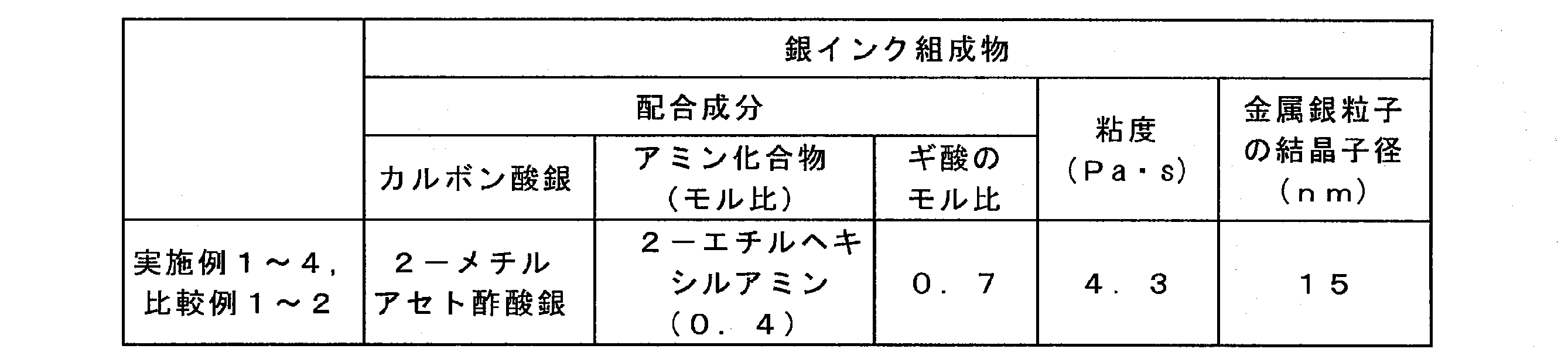
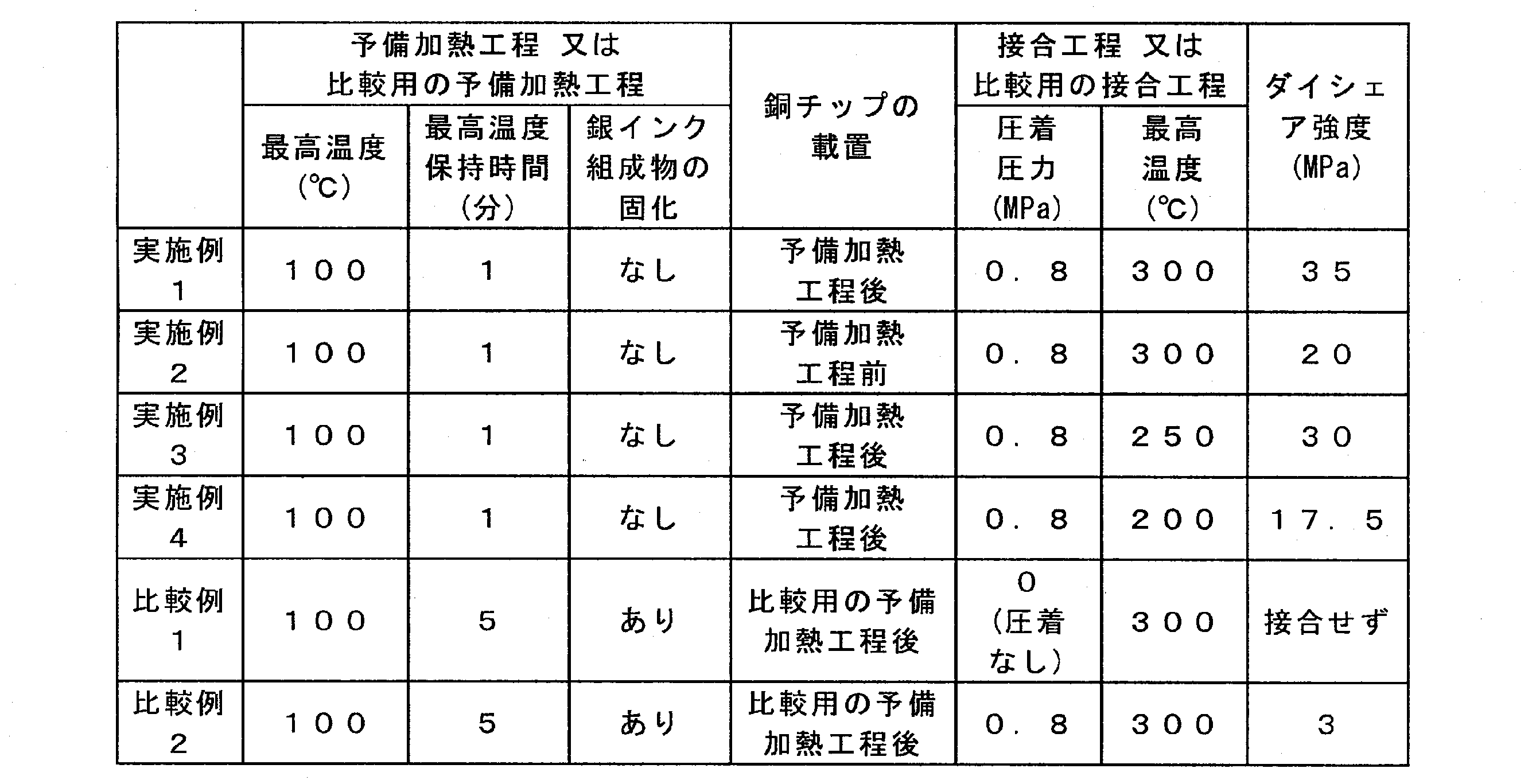
上記結果から明らかなように、実施例1~4においては、予備加熱工程及び接合工程を行うことにより、金属製部材接合体のダイシェア強度が17.5MPa以上(17.5~35MPa)であり、接合強度が十分に高かった。特に、実施例1及び2の結果から、銅チップの載置を予備加熱工程後に行う(すなわち、予備加熱方法(B1)を採用する)ことで、接合強度がより高くなることが確認された。
実施例1~4においては、いずれも、予備加熱工程の間、銀インク組成物は固化せず、流動性を維持していた。これは、銀インク組成物に泡立ちが見られたことから明らかであった。実施例2においては、予備加熱工程の間、銀インク組成物(印刷層)の主要な面が銅チップで被覆されており、露出しておらず、銀インク組成物の泡立ちを直接確認できなかったが、銅チップに僅かながら揺らぎが認められたことで、銀インク組成物に泡立ちが生じていることを間接的に確認できた。
また、実施例1~4においては、いずれも、銀インク組成物の泡立ちが予備加熱工程の終了時までには消失しており、この段階で銀インク組成物からのガスの発生が、ほぼ又は完全に終了していたと推測された。
また、実施例1~4においては、いずれも、銀インク組成物の泡立ちが予備加熱工程の終了時までには消失しており、この段階で銀インク組成物からのガスの発生が、ほぼ又は完全に終了していたと推測された。
これに対して、比較例1においては、金属製部材接合体を得られなかった。これは、比較用の予備加熱工程の終了時に、銀インク組成物が固化していたこと、比較用の接合工程において、前記加熱物の焼成時に銅板と銅チップを圧着しなかったこと、が原因であった。
比較例1においては、銀インク組成物の温度が100℃に到達後、当初は、泡立ちが認められたが、この泡立ちが消失する前に、銀インク組成物が固化してしまい、銀インク組成物の加熱物の表面が、泡立ちの影響で、実施例1~4の場合よりも荒れていた。
比較例1においては、銀インク組成物の温度が100℃に到達後、当初は、泡立ちが認められたが、この泡立ちが消失する前に、銀インク組成物が固化してしまい、銀インク組成物の加熱物の表面が、泡立ちの影響で、実施例1~4の場合よりも荒れていた。
比較例2においては、金属製部材接合体のダイシェア強度が3MPaであり、接合強度が低かった。これは、比較用の予備加熱工程の終了時に、銀インク組成物が固化していたことが原因であった。
比較例2においても、比較例1の場合と同様に、銀インク組成物の温度が100℃に到達後、当初は、泡立ちが認められたが、この泡立ちが消失する前に、銀インク組成物が固化してしまい、銀インク組成物の加熱物の表面が、泡立ちの影響で、実施例1~4の場合よりも荒れていた。
ただし、比較例2では、比較例1の場合とは異なり、接合工程において、前記加熱物の焼成時に銅板と銅チップを圧着したため、金属製部材接合体は得られた。
比較例2においても、比較例1の場合と同様に、銀インク組成物の温度が100℃に到達後、当初は、泡立ちが認められたが、この泡立ちが消失する前に、銀インク組成物が固化してしまい、銀インク組成物の加熱物の表面が、泡立ちの影響で、実施例1~4の場合よりも荒れていた。
ただし、比較例2では、比較例1の場合とは異なり、接合工程において、前記加熱物の焼成時に銅板と銅チップを圧着したため、金属製部材接合体は得られた。
図9は、実施例1における、銅チップと金属銀(導電性接合部)との境界と、その近傍領域の、TEMによる撮像データである。
図9中、画像左側の領域は銅チップであり、画像右側の領域は金属銀である。
図9中、矢印で示すものも含めた色抜け部分は、微小な空隙部(本明細書及び図面においては、「マイクロボイド」と称することがある)である。
図9から明らかなように、銅チップと金属銀との間には、画像上下に渡り、他の領域と区別可能な2つの領域、すなわち領域9-1及び領域9-2が認められた。
図9中、画像左側の領域は銅チップであり、画像右側の領域は金属銀である。
図9中、矢印で示すものも含めた色抜け部分は、微小な空隙部(本明細書及び図面においては、「マイクロボイド」と称することがある)である。
図9から明らかなように、銅チップと金属銀との間には、画像上下に渡り、他の領域と区別可能な2つの領域、すなわち領域9-1及び領域9-2が認められた。
図10は、図9と同じ領域の、EDS(EDX)による銀元素検出時の撮像データである。
図10中にも、図9の場合と同様に、銅チップと金属銀との間には、画像上下に渡り、他の領域と区別可能な2つの領域、すなわち領域10-1及び領域10-2が認められた。領域10-1の形状は、領域9-1の形状と類似しており、領域10-2の形状は、領域9-2の形状と類似してした。
取得した撮像データは、金属銀の領域と領域10-1において蛍光が発生していることを示しており、これらの領域で銀元素が検出された。一方、この撮像データは、領域10-2も含めて他の領域においては、有意に蛍光が発生していることを示しておらず、これらの領域で銀元素は有意に検出されなかった。
図10中にも、図9の場合と同様に、銅チップと金属銀との間には、画像上下に渡り、他の領域と区別可能な2つの領域、すなわち領域10-1及び領域10-2が認められた。領域10-1の形状は、領域9-1の形状と類似しており、領域10-2の形状は、領域9-2の形状と類似してした。
取得した撮像データは、金属銀の領域と領域10-1において蛍光が発生していることを示しており、これらの領域で銀元素が検出された。一方、この撮像データは、領域10-2も含めて他の領域においては、有意に蛍光が発生していることを示しておらず、これらの領域で銀元素は有意に検出されなかった。
図11は、図9と同じ領域の、EDS(EDX)による銅元素検出時の撮像データである。
図11中にも、図9の場合と同様に、銅チップと金属銀との間には、画像上下に渡り、他の領域と区別可能な2つの領域、すなわち領域11-1及び領域11-2が認められた。領域11-1の形状は、領域9-1の形状と類似しており、領域11-2の形状は、領域9-2の形状と類似してした。
取得した撮像データは、銅チップの領域と、領域11-2において蛍光が発生していることを示しており、これらの領域で銅元素が検出された。一方、この撮像データは、領域11-1も含めて他の領域においては、有意に蛍光が発生していることを示しておらず、これらの領域で銅元素は有意に検出されなかった。
図11中にも、図9の場合と同様に、銅チップと金属銀との間には、画像上下に渡り、他の領域と区別可能な2つの領域、すなわち領域11-1及び領域11-2が認められた。領域11-1の形状は、領域9-1の形状と類似しており、領域11-2の形状は、領域9-2の形状と類似してした。
取得した撮像データは、銅チップの領域と、領域11-2において蛍光が発生していることを示しており、これらの領域で銅元素が検出された。一方、この撮像データは、領域11-1も含めて他の領域においては、有意に蛍光が発生していることを示しておらず、これらの領域で銅元素は有意に検出されなかった。
図12は、図9と同じ領域の、EDS(EDX)による酸素元素検出時の撮像データである。
図12中には、図9の場合とは異なり、銅チップと金属銀との間には、画像上下に渡り、他の領域と区別可能な1つの領域、すなわち領域12-1が認められた。そして、領域12-1の形状は、領域9-2の形状と類似してした。
取得した撮像データは、領域12-1において蛍光が発生していることを示しており、この領域で酸素元素が検出された。一方、この撮像データは、他の領域においては、微弱な蛍光の発生を示唆していたが、その蛍光強度は、領域12-1での蛍光強度と比較すると軽微であり、酸素元素の検出量は微量であった。
図12中には、図9の場合とは異なり、銅チップと金属銀との間には、画像上下に渡り、他の領域と区別可能な1つの領域、すなわち領域12-1が認められた。そして、領域12-1の形状は、領域9-2の形状と類似してした。
取得した撮像データは、領域12-1において蛍光が発生していることを示しており、この領域で酸素元素が検出された。一方、この撮像データは、他の領域においては、微弱な蛍光の発生を示唆していたが、その蛍光強度は、領域12-1での蛍光強度と比較すると軽微であり、酸素元素の検出量は微量であった。
以上の結果から、領域9-1、領域10-1、及び領域11-1は、同じ領域を示しており、この領域は、銀を主要構成元素とする層であることが判明した。
また、領域9-2、領域10-2、領域11-2、及び領域12-1は、同じ領域を示しており、この領域は、銅及び酸素を主要構成元素とする層であることが判明した。
すなわち、上記で得られた金属製部材接合体は、銅チップと金属銀との間に、銅チップ側から金属銀側へ向けて、銀を主要構成元素とする層と、銅及び酸素を主要構成元素とする層と、をこの順に備えていることが判明した。このように、金属製部材接合体は、銅チップ、銀を主要構成元素とする層、銅及び酸素を主要構成元素とする層、及び金属銀がこの順に存在する積層構造を有し、銀元素と銅元素とが交互に配置されていた。
また、領域9-2、領域10-2、領域11-2、及び領域12-1は、同じ領域を示しており、この領域は、銅及び酸素を主要構成元素とする層であることが判明した。
すなわち、上記で得られた金属製部材接合体は、銅チップと金属銀との間に、銅チップ側から金属銀側へ向けて、銀を主要構成元素とする層と、銅及び酸素を主要構成元素とする層と、をこの順に備えていることが判明した。このように、金属製部材接合体は、銅チップ、銀を主要構成元素とする層、銅及び酸素を主要構成元素とする層、及び金属銀がこの順に存在する積層構造を有し、銀元素と銅元素とが交互に配置されていた。
上記の結果は、銅チップと金属銀(導電性接合部)との境界と、その近傍領域での分析によって得られたものであるが、金属製部材接合体の反対側、すなわち、銅板と金属銀(導電性接合部)との境界と、その近傍領域での分析でも、同様の結果が得られた。
すなわち、金属製部材接合体は、銅板と金属銀との間に、銅板側から金属銀側へ向けて、銀を主要構成元素とする層と、銅及び酸素を主要構成元素とする層と、をこの順に備えていることが判明した。このように、金属製部材接合体は、銅板、銀を主要構成元素とする層、銅及び酸素を主要構成元素とする層、及び金属銀がこの順に存在する積層構造を有し、銀元素と銅元素とが交互に配置されていた。
すなわち、金属製部材接合体は、銅板と金属銀との間に、銅板側から金属銀側へ向けて、銀を主要構成元素とする層と、銅及び酸素を主要構成元素とする層と、をこの順に備えていることが判明した。このように、金属製部材接合体は、銅板、銀を主要構成元素とする層、銅及び酸素を主要構成元素とする層、及び金属銀がこの順に存在する積層構造を有し、銀元素と銅元素とが交互に配置されていた。
上記の銅チップ側及び銅板側の両方の、銅及び酸素を主要構成元素とする層においては、酸素は、酸化銅のような銅と反応した生成物として存在している可能性があり、銅と反応せずに単独で存在している可能性もあった。
金属製部材接合体が上記のような積層構造を有していることは、金属製部材接合体のダイシェア強度が十分に大きいことと整合していた。
本発明は、回路基板をはじめとする、金属製部材接合体を備えた各種装置の製造に利用可能である。
1,2・・・金属製部材接合体、11・・・金属製の第1部材、11a・・・金属製の第1部材の第1面、12・・・金属製の第2部材、12a・・・金属製の第2部材の第1面、13,23・・・金属銀(導電性接合部)、130・・・銀インク組成物、130’・・・銀インク組成物の加熱物
Claims (15)
- 金属製部材同士を接合する方法であって、
金属製の第1部材と、金属製の第2部材と、のいずれか一方又は両方の表面に付着している銀インク組成物を、60℃以上の温度で固化させずに加熱することにより、前記銀インク組成物の加熱物を得る工程と、
前記銀インク組成物の加熱物を介在させて、前記第1部材と前記第2部材とを圧着しながら、前記加熱物を焼成することにより、前記第1部材と前記第2部材とを、金属銀によって接合する工程と、を有し、
前記銀インク組成物が、式「-COOAg」で表される基を有するカルボン酸銀と、アミン化合物と、ギ酸と、が配合されてなり、前記銀インク組成物が、その焼成によって金属銀を形成するための材料である、金属製部材の接合方法。 - 60℃以上の温度で固化させずに加熱する前の前記銀インク組成物が、前記カルボン酸銀から生成した金属銀の粒子を含有し、
前記金属銀の粒子の結晶子径が20nm未満である、請求項1に記載の金属製部材の接合方法。 - 前記カルボン酸銀が、下記一般式(1):

Y1はそれぞれ独立にフッ素原子、塩素原子、臭素原子又は水素原子であり;R1は炭素数1~19の脂肪族炭化水素基又はフェニル基であり;R2は炭素数1~20の脂肪族炭化水素基であり;R3は炭素数1~16の脂肪族炭化水素基であり;R4及びR5はそれぞれ独立に炭素数1~18の脂肪族炭化水素基であり;R6は炭素数1~19の脂肪族炭化水素基、水酸基又は式「AgO-」で表される基であり;
X1はそれぞれ独立に水素原子、炭素数1~20の脂肪族炭化水素基、ハロゲン原子、1個以上の水素原子が置換基で置換されていてもよいフェニル基若しくはベンジル基、シアノ基、N-フタロイル-3-アミノプロピル基、2-エトキシビニル基、又は一般式「R7O-」、「R7S-」、「R7-C(=O)-」若しくは「R7-C(=O)-O-」で表される基であり;
R7は、炭素数1~10の脂肪族炭化水素基、チエニル基、又は1個以上の水素原子が置換基で置換されていてもよいフェニル基若しくはジフェニル基である。)
で表わされるβ-ケトカルボン酸銀である、請求項1又は2に記載の金属製部材の接合方法。 - 前記第1部材及び第2部材を構成する金属が、銅、銀、金、パラジウム、ニッケル、又は、銅、銀、金、パラジウム及びニッケルからなる群より選択される1種又は2種以上を含む合金である、請求項1~3のいずれか一項に記載の金属製部材の接合方法。
- 前記銀インク組成物の加熱物を得る工程において、前記第1部材の表面に前記銀インク組成物が付着している場合には、前記第1部材の前記銀インク組成物が付着していない箇所を直接加熱することで、前記銀インク組成物を加熱し、前記第2部材の表面に前記銀インク組成物が付着している場合には、前記第2部材の前記銀インク組成物が付着していない箇所を直接加熱することで、前記銀インク組成物を加熱する、請求項1~4のいずれか一項に記載の金属製部材の接合方法。
- 前記第1部材及び第2部材が、板状又は棒状であり、
前記第1部材の接合面における1辺の長さと、前記第2部材の接合面における1辺の長さとが、互いに同一であってもよいし、互いに異なっていてもよく、いずれも0.01~30mmである、請求項1~5のいずれか一項に記載の金属製部材の接合方法。 - 前記第1部材及び第2部材が、板状又は棒状であり、
前記第1部材の厚さと、前記第2部材の厚さとが、互いに同一であってもよいし、互いに異なっていてもよく、いずれも0.01~5mmである、請求項1~6のいずれか一項に記載の金属製部材の接合方法。 - 前記第1部材と前記第2部材と、のいずれか一方又は両方の表面における前記加熱物の厚さが、100μm以上である、請求項1~7のいずれか一項に記載の金属製部材の接合方法。
- 前記銀インク組成物の加熱物を得る工程の終了後に、前記加熱物を介して、前記第1部材及び第2部材を接触させるか、又は、前記銀インク組成物の加熱物を得る工程の途中で、加熱中の前記銀インク組成物を介して、前記第1部材及び第2部材を接触させる、請求項1~8のいずれか一項に記載の金属製部材の接合方法。
- 前記第1部材と前記第2部材とを、金属銀によって接合する工程において、前記第1部材と前記第2部材との圧着を開始してから、前記加熱物の焼成を開始する、請求項1~9のいずれか一項に記載の金属製部材の接合方法。
- 前記第1部材と前記第2部材とを、金属銀によって接合する工程において、前記銀インク組成物の加熱物を介在させて、前記第1部材と前記第2部材とを圧着するときの圧力が、0.2MPa以上である、請求項1~10のいずれか一項に記載の金属製部材の接合方法。
- 請求項1~11のいずれか一項に記載の金属製部材の接合方法により得られた、金属製部材接合体であって、
前記金属製部材接合体のダイシェア強度が15MPa以上である、金属製部材接合体。 - 金属製部材接合体であって、
前記金属製部材接合体は、金属製の第1部材と、金属製の第2部材と、が金属銀を介して接合されて、構成されており、
前記第1部材及び第2部材のいずれか一方又は両方が、銅製であり、
前記第1部材が銅製である場合には、前記金属製部材接合体は、前記第1部材と前記金属銀との間に、前記第1部材側から前記金属銀側へ向けて、銀を主要構成元素とする層と、銅及び酸素を主要構成元素とする層と、をこの順に備えており、
前記第2部材が銅製である場合には、前記金属製部材接合体は、前記第2部材と前記金属銀との間に、前記第2部材側から前記金属銀側へ向けて、銀を主要構成元素とする層と、銅及び酸素を主要構成元素とする層と、をこの順に備えており、
前記金属製部材接合体のダイシェア強度が15MPa以上である、金属製部材接合体。 - 前記金属銀の厚さが10μm以上である、請求項12又は13に記載の金属製部材接合体。
- 請求項12~14のいずれか一項に記載の金属製部材接合体を、有機基板上に備え、
前記金属製部材が金属電極である、回路基板。
Applications Claiming Priority (4)
| Application Number | Priority Date | Filing Date | Title |
|---|---|---|---|
| JP2018189518 | 2018-10-04 | ||
| JP2018-189518 | 2018-10-04 | ||
| JP2019-097680 | 2019-05-24 | ||
| JP2019097680 | 2019-05-24 |
Publications (1)
| Publication Number | Publication Date |
|---|---|
| WO2020071471A1 true WO2020071471A1 (ja) | 2020-04-09 |
Family
ID=70054814
Family Applications (1)
| Application Number | Title | Priority Date | Filing Date |
|---|---|---|---|
| PCT/JP2019/039066 Ceased WO2020071471A1 (ja) | 2018-10-04 | 2019-10-03 | 金属製部材の接合方法、金属製部材接合体及び回路基板 |
Country Status (2)
| Country | Link |
|---|---|
| JP (3) | JP7418731B2 (ja) |
| WO (1) | WO2020071471A1 (ja) |
Families Citing this family (1)
| Publication number | Priority date | Publication date | Assignee | Title |
|---|---|---|---|---|
| WO2025205561A1 (ja) * | 2024-03-28 | 2025-10-02 | 国立大学法人大阪大学 | 接合材及び該接合材を用いた接合方法 |
Citations (4)
| Publication number | Priority date | Publication date | Assignee | Title |
|---|---|---|---|---|
| JP2008159535A (ja) * | 2006-12-26 | 2008-07-10 | Osaka Industrial Promotion Organization | β−ケトカルボン酸銀から得られる金属銀を含む銀ペーストおよびその製造方法 |
| JP2013214733A (ja) * | 2012-03-05 | 2013-10-17 | Namics Corp | 熱伝導性ペースト及びその使用 |
| JP2014193991A (ja) * | 2012-09-28 | 2014-10-09 | Toppan Forms Co Ltd | 銀インク組成物、導電体及び通信機器 |
| JP2016010959A (ja) * | 2014-06-30 | 2016-01-21 | トッパン・フォームズ株式会社 | 積層体及び回路基板 |
Family Cites Families (11)
| Publication number | Priority date | Publication date | Assignee | Title |
|---|---|---|---|---|
| JP2004179205A (ja) * | 2002-11-25 | 2004-06-24 | Ricoh Co Ltd | 半導体素子、ハンダボール転写シート、インクジェット方式によるバンプ形成方法及びインク組成物 |
| JP5611537B2 (ja) * | 2009-04-28 | 2014-10-22 | 日立化成株式会社 | 導電性接合材料、それを用いた接合方法、並びにそれによって接合された半導体装置 |
| KR102059805B1 (ko) * | 2012-09-28 | 2019-12-27 | 돗빤호무즈가부시기가이샤 | 은 잉크 조성물, 도전체 및 통신 기기 |
| US10849231B2 (en) * | 2013-03-29 | 2020-11-24 | Toppan Forms Co., Ltd. | Laminate and circuit board |
| JP6121804B2 (ja) * | 2013-06-04 | 2017-04-26 | Dowaエレクトロニクス株式会社 | 接合材およびその接合材を用いて電子部品を接合する方法 |
| JP2015181160A (ja) * | 2014-03-05 | 2015-10-15 | トッパン・フォームズ株式会社 | 導電パターンの形成方法及び導電性配線 |
| KR101771815B1 (ko) * | 2015-12-04 | 2017-08-25 | 삼성전기주식회사 | 금속 연결 구조 및 그 제조 방법 |
| EP3208842A1 (de) * | 2016-02-19 | 2017-08-23 | Heraeus Deutschland GmbH & Co. KG | Verfahren zur herstellung einer substratplatte, substratplatte, verfahren zur herstellung eines halbleitermoduls und halbleitermodul |
| JP2017155166A (ja) * | 2016-03-03 | 2017-09-07 | バンドー化学株式会社 | 接合用組成物 |
| JP6796937B2 (ja) * | 2016-03-16 | 2020-12-09 | 日東電工株式会社 | 接合体の製造方法 |
| JP2018193604A (ja) * | 2017-05-22 | 2018-12-06 | パナソニックIpマネジメント株式会社 | 接合構造及びその製造方法 |
-
2019
- 2019-09-30 JP JP2019178595A patent/JP7418731B2/ja active Active
- 2019-10-03 WO PCT/JP2019/039066 patent/WO2020071471A1/ja not_active Ceased
-
2023
- 2023-04-21 JP JP2023070280A patent/JP7545149B2/ja active Active
-
2024
- 2024-08-14 JP JP2024135487A patent/JP2024159786A/ja active Pending
Patent Citations (4)
| Publication number | Priority date | Publication date | Assignee | Title |
|---|---|---|---|---|
| JP2008159535A (ja) * | 2006-12-26 | 2008-07-10 | Osaka Industrial Promotion Organization | β−ケトカルボン酸銀から得られる金属銀を含む銀ペーストおよびその製造方法 |
| JP2013214733A (ja) * | 2012-03-05 | 2013-10-17 | Namics Corp | 熱伝導性ペースト及びその使用 |
| JP2014193991A (ja) * | 2012-09-28 | 2014-10-09 | Toppan Forms Co Ltd | 銀インク組成物、導電体及び通信機器 |
| JP2016010959A (ja) * | 2014-06-30 | 2016-01-21 | トッパン・フォームズ株式会社 | 積層体及び回路基板 |
Also Published As
| Publication number | Publication date |
|---|---|
| JP2023101484A (ja) | 2023-07-21 |
| JP7545149B2 (ja) | 2024-09-04 |
| JP7418731B2 (ja) | 2024-01-22 |
| JP2024159786A (ja) | 2024-11-08 |
| JP2020193318A (ja) | 2020-12-03 |
Similar Documents
| Publication | Publication Date | Title |
|---|---|---|
| KR102345811B1 (ko) | 도전성 조성물 및 그것을 사용한 전자 부품 | |
| JP5212298B2 (ja) | パワーモジュール用基板、冷却器付パワーモジュール用基板、パワーモジュール及びパワーモジュール用基板の製造方法 | |
| KR20180004853A (ko) | 접합재료, 접합체, 및 접합방법 | |
| CN103008910A (zh) | 用于将电子部件连接到基板上的膏和方法 | |
| JP7591631B2 (ja) | 焼結組成物 | |
| JP7139590B2 (ja) | 導体形成用組成物、並びに接合体及びその製造方法 | |
| JP7545149B2 (ja) | 金属製部材接合体 | |
| WO2018030173A1 (ja) | 接合用組成物及びその製造方法 | |
| JP7823321B2 (ja) | 銀焼結体、半導体装置、銀含有組成物、及び銀焼結体の製造方法 | |
| TWI651814B (zh) | 附有Ag基材層之功率模組用基板及功率模組 | |
| JP5707885B2 (ja) | パワーモジュール用基板、冷却器付パワーモジュール用基板、パワーモジュール及びパワーモジュール用基板の製造方法 | |
| US20240278321A1 (en) | Sintered material, metal sintered compact, method for producing sintered material, method for producing joined body, and joined body | |
| JP6712949B2 (ja) | 金属銀、金属銀の製造方法及び積層体 | |
| JP2023064058A (ja) | 焼結材、金属焼結体、焼結材の製造方法、接合体の製造方法、及び接合体 | |
| JP7718085B2 (ja) | 組成物 | |
| JP2024021290A (ja) | 銀含有組成物及び金属製部材接合体 | |
| JP6468776B2 (ja) | 銀インク組成物の製造方法 | |
| JP6604468B2 (ja) | 金属銀の製造方法 | |
| CN102810524A (zh) | 功率模块及功率模块的制造方法 | |
| JP6267835B1 (ja) | 接合用組成物及びその製造方法 | |
| JP2019197682A (ja) | 積層体 | |
| JP6502749B2 (ja) | 接合性導体ペースト | |
| JP2014193991A (ja) | 銀インク組成物、導電体及び通信機器 | |
| JP2014089926A (ja) | 銀膜 | |
| JP6289988B2 (ja) | 銀インク組成物の製造方法 |
Legal Events
| Date | Code | Title | Description |
|---|---|---|---|
| 121 | Ep: the epo has been informed by wipo that ep was designated in this application |
Ref document number: 19868927 Country of ref document: EP Kind code of ref document: A1 |
|
| NENP | Non-entry into the national phase |
Ref country code: DE |
|
| 122 | Ep: pct application non-entry in european phase |
Ref document number: 19868927 Country of ref document: EP Kind code of ref document: A1 |