WO2020071065A1 - 排ガス浄化触媒 - Google Patents
排ガス浄化触媒Info
- Publication number
- WO2020071065A1 WO2020071065A1 PCT/JP2019/035553 JP2019035553W WO2020071065A1 WO 2020071065 A1 WO2020071065 A1 WO 2020071065A1 JP 2019035553 W JP2019035553 W JP 2019035553W WO 2020071065 A1 WO2020071065 A1 WO 2020071065A1
- Authority
- WO
- WIPO (PCT)
- Prior art keywords
- exhaust gas
- partition wall
- palladium
- catalyst
- rhodium
- Prior art date
- Legal status (The legal status is an assumption and is not a legal conclusion. Google has not performed a legal analysis and makes no representation as to the accuracy of the status listed.)
- Ceased
Links
Images




Classifications
-
- B—PERFORMING OPERATIONS; TRANSPORTING
- B01—PHYSICAL OR CHEMICAL PROCESSES OR APPARATUS IN GENERAL
- B01D—SEPARATION
- B01D53/00—Separation of gases or vapours; Recovering vapours of volatile solvents from gases; Chemical or biological purification of waste gases, e.g. engine exhaust gases, smoke, fumes, flue gases, aerosols
- B01D53/34—Chemical or biological purification of waste gases
- B01D53/92—Chemical or biological purification of waste gases of engine exhaust gases
- B01D53/94—Chemical or biological purification of waste gases of engine exhaust gases by catalytic processes
-
- B—PERFORMING OPERATIONS; TRANSPORTING
- B01—PHYSICAL OR CHEMICAL PROCESSES OR APPARATUS IN GENERAL
- B01J—CHEMICAL OR PHYSICAL PROCESSES, e.g. CATALYSIS OR COLLOID CHEMISTRY; THEIR RELEVANT APPARATUS
- B01J23/00—Catalysts comprising metals or metal oxides or hydroxides, not provided for in group B01J21/00
- B01J23/38—Catalysts comprising metals or metal oxides or hydroxides, not provided for in group B01J21/00 of noble metals
- B01J23/40—Catalysts comprising metals or metal oxides or hydroxides, not provided for in group B01J21/00 of noble metals of the platinum group metals
- B01J23/46—Ruthenium, rhodium, osmium or iridium
-
- F—MECHANICAL ENGINEERING; LIGHTING; HEATING; WEAPONS; BLASTING
- F01—MACHINES OR ENGINES IN GENERAL; ENGINE PLANTS IN GENERAL; STEAM ENGINES
- F01N—GAS-FLOW SILENCERS OR EXHAUST APPARATUS FOR MACHINES OR ENGINES IN GENERAL; GAS-FLOW SILENCERS OR EXHAUST APPARATUS FOR INTERNAL-COMBUSTION ENGINES
- F01N3/00—Exhaust or silencing apparatus having means for purifying, rendering innocuous, or otherwise treating exhaust
- F01N3/02—Exhaust or silencing apparatus having means for purifying, rendering innocuous, or otherwise treating exhaust for cooling, or for removing solid constituents of, exhaust
- F01N3/021—Exhaust or silencing apparatus having means for purifying, rendering innocuous, or otherwise treating exhaust for cooling, or for removing solid constituents of, exhaust by means of filters
- F01N3/033—Exhaust or silencing apparatus having means for purifying, rendering innocuous, or otherwise treating exhaust for cooling, or for removing solid constituents of, exhaust by means of filters in combination with other devices
- F01N3/035—Exhaust or silencing apparatus having means for purifying, rendering innocuous, or otherwise treating exhaust for cooling, or for removing solid constituents of, exhaust by means of filters in combination with other devices with catalytic reactors
-
- F—MECHANICAL ENGINEERING; LIGHTING; HEATING; WEAPONS; BLASTING
- F01—MACHINES OR ENGINES IN GENERAL; ENGINE PLANTS IN GENERAL; STEAM ENGINES
- F01N—GAS-FLOW SILENCERS OR EXHAUST APPARATUS FOR MACHINES OR ENGINES IN GENERAL; GAS-FLOW SILENCERS OR EXHAUST APPARATUS FOR INTERNAL-COMBUSTION ENGINES
- F01N3/00—Exhaust or silencing apparatus having means for purifying, rendering innocuous, or otherwise treating exhaust
- F01N3/08—Exhaust or silencing apparatus having means for purifying, rendering innocuous, or otherwise treating exhaust for rendering innocuous
- F01N3/10—Exhaust or silencing apparatus having means for purifying, rendering innocuous, or otherwise treating exhaust for rendering innocuous by thermal or catalytic conversion of noxious components of exhaust
-
- F—MECHANICAL ENGINEERING; LIGHTING; HEATING; WEAPONS; BLASTING
- F01—MACHINES OR ENGINES IN GENERAL; ENGINE PLANTS IN GENERAL; STEAM ENGINES
- F01N—GAS-FLOW SILENCERS OR EXHAUST APPARATUS FOR MACHINES OR ENGINES IN GENERAL; GAS-FLOW SILENCERS OR EXHAUST APPARATUS FOR INTERNAL-COMBUSTION ENGINES
- F01N3/00—Exhaust or silencing apparatus having means for purifying, rendering innocuous, or otherwise treating exhaust
- F01N3/08—Exhaust or silencing apparatus having means for purifying, rendering innocuous, or otherwise treating exhaust for rendering innocuous
- F01N3/10—Exhaust or silencing apparatus having means for purifying, rendering innocuous, or otherwise treating exhaust for rendering innocuous by thermal or catalytic conversion of noxious components of exhaust
- F01N3/24—Exhaust or silencing apparatus having means for purifying, rendering innocuous, or otherwise treating exhaust for rendering innocuous by thermal or catalytic conversion of noxious components of exhaust characterised by constructional aspects of converting apparatus
- F01N3/28—Construction of catalytic reactors
-
- B—PERFORMING OPERATIONS; TRANSPORTING
- B01—PHYSICAL OR CHEMICAL PROCESSES OR APPARATUS IN GENERAL
- B01J—CHEMICAL OR PHYSICAL PROCESSES, e.g. CATALYSIS OR COLLOID CHEMISTRY; THEIR RELEVANT APPARATUS
- B01J35/00—Catalysts, in general, characterised by their form or physical properties
- B01J35/50—Catalysts, in general, characterised by their form or physical properties characterised by their shape or configuration
- B01J35/56—Foraminous structures having flow-through passages or channels, e.g. grids or three-dimensional [3D] monoliths
Definitions
- the present invention relates to an exhaust gas purifying catalyst having a catalyst layer containing at least rhodium and palladium.
- an exhaust gas purifying catalyst for purifying exhaust gas (exhaust gas) of an internal combustion engine a catalyst in which a catalyst is carried on a wall flow type carrier is known. That is, a catalyst component is fixed inside a carrier having a large number of micropores formed therethrough and exhaust gas is circulated, and carbon monoxide, unburned combustion components, nitrogen oxides, particulate matter contained in the exhaust gas are contained. (PM).
- Examples of the type of the carrier include a ceramic molded product and a metal product (metal carrier).
- the type of the catalyst supported on the carrier is variously selected according to the substance to be purified (see Patent Documents 1 to 3).
- One of the objects of the present invention was created in view of the above-mentioned problems, and it is an object of the present invention to provide an exhaust gas purifying catalyst capable of efficiently improving exhaust gas purifying performance. It is to be noted that the present invention is not limited to this object, and is an operation and effect derived from each configuration shown in “Embodiments for carrying out the invention” described later, and it is possible to obtain an operation and effect that cannot be obtained by the conventional technology. Can be positioned as an objective.
- the disclosed exhaust gas purifying catalyst has a catalyst layer containing at least rhodium and palladium. Further, the rhodium is supported at least on the surface of the partition wall of the carrier, and the palladium is supported at least inside the partition wall of the carrier. Further, the carrying density of the palladium is higher on the upstream side than on the downstream side. (2) It is preferable to include an upstream portion containing the palladium and a downstream portion not containing the palladium.
- the upstream portion includes a surface layer portion provided on the partition wall surface of the carrier and containing the rhodium, and the downstream portion preferably contains the rhodium inside the partition wall of the carrier.
- the first pore diameter on the partition wall surface is larger than the second pore diameter inside the partition wall.
- the first particle size of the base material for fixing the catalyst on the partition wall surface is larger than the second particle size of the base material for fixing the catalyst inside the partition wall.
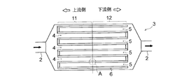
- FIG. 1 is a diagram showing the inside of a vehicle to which an exhaust gas purifying catalyst is applied. It is a sectional view showing the structure of an exhaust gas purifying catalyst. It is sectional drawing which expands and shows the internal structure of an exhaust gas purification catalyst.
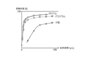
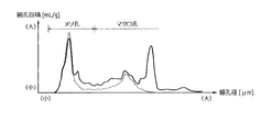
- 4 is a graph showing a relationship between a catalyst carrying density and a purification efficiency. 4 is a graph showing a relationship between a pore diameter and a pore amount.
- (A) to (C) are graphs showing changes in purification efficiency. It is a figure for explaining a modification.
- the exhaust gas purifying catalyst 3 of the present invention is applied to a vehicle 10 equipped with an engine 1 (internal combustion engine).
- the type of the engine 1 may be a diesel engine or a gasoline engine.
- the exhaust gas purifying catalyst 3 is interposed in the exhaust passage 2 of the engine 1.
- the exhaust gas purification catalyst 3 is a catalyst device for efficiently purifying various harmful components contained in exhaust gas, and has both a function as a three-way catalyst and a function as a PM removal filter.
- the disposition position of the exhaust gas purifying catalyst 3 is preferably set to a position through which high-temperature exhaust gas passes, in order to ensure catalytic reactivity. For example, as shown in FIG. 1, it may be arranged at a position close to the engine 1 (directly downstream of the exhaust manifold, directly downstream of the supercharger, or the like).
- a porous body in which a number of flow paths through which exhaust gas can pass are formed.
- the porous body is obtained by supporting a catalyst 9 on a porous carrier 7 via a base material 8, and is formed in a cylindrical shape, an elliptic cylindrical shape, or a rectangular parallelepiped shape.
- the material of the carrier 7 may be a ceramic such as silicon carbide or cordierite (cordierite) or a metal foil.
- the porosity of the carrier 7 is preferably as high as possible.
- the carrier 7 of the present embodiment has a porosity exceeding 50 [%] and a pore volume of pores having a diameter of 1 [ ⁇ m] or more exceeding 0.2 [mL / g].
- Examples of the base material 8 for supporting the catalyst 9 include aluminum oxide (alumina, Al 2 O 3 ), cerium oxide (ceria, CeO 2 ), and zirconium oxide (zirconia, ZrO 2 ).
- the base material 8 may include an oxygen storage material that stores oxygen under an oxidizing atmosphere.
- Examples of the oxygen storage material include a ceria-zirconia composite oxide (CeO 2 -ZrO 2 -based substance) and a rare earth oxysulfate (Ln 2 O 2 SO 4 ).
- the porous body shown in FIG. 2 is obtained by fixing a base material 8 and a catalyst 9 to a carrier 7 having a honeycomb structure.
- the inside of the carrier 7 is divided into a plurality of cells (small chamber-like passages) along the flow direction of the exhaust gas.
- Each cell is defined by a porous partition wall 6 (rib), and the end on the inlet side or the outlet side is closed.
- the cell whose end on the outlet side is closed is referred to as an inlet cell 4.
- a cell whose end on the inlet side is closed is referred to as an outlet cell 5.
- a portion of the carrier 7 on the upstream side is referred to as an upstream portion 11, and a portion of the carrier 7 on the downstream side (exit side) is referred to as a downstream portion 12.
- Each inlet cell 4 is arranged adjacent to at least one or more outlet cells 5, and is preferably arranged adjacent to a number of outlet cells 5.
- the exhaust gas flowing from the inlet of the exhaust gas purifying catalyst 3 first enters the inlet cell 4, passes through the partition 6, then enters the outlet cell 5, and flows out of the outlet of the exhaust gas purifying catalyst 3. I do.
- the catalyst 9 is supported on the inside of the partition 6 that partitions the inlet cell 4 and the outlet cell 5 and on the side of the surface of the partition 6 that faces the inlet cell 4.
- the inside of the partition 6 is referred to as “partition inside”, and the surface of the partition 6 facing the inlet cell 4 is simply referred to as “partition surface”.
- the catalyst 9 contains at least rhodium (Rh) and palladium (Pd). Rhodium is supported on at least the partition wall surface of the carrier 7. On the other hand, palladium is carried at least inside the partition walls of the carrier 7.
- the carrying density of palladium is higher in the upstream portion 11 than in the downstream portion 12. For example, when palladium is not contained in the partition wall surface, the carrying density of palladium in the inside of the partition wall in the upstream portion 11 is higher than that in the partition wall in the downstream portion 12.
- the carrying density of palladium on the partition wall surface is higher on the upstream side than on the downstream side.
- FIG. 3 is an enlarged cross-sectional view showing a portion A in FIG.
- the positions where the base material 8 and the catalyst 9 are fixed to the carrier 7 can be classified into an upstream portion 11 and a downstream portion 12, and can be further classified into the inside of the partition wall and the partition wall surface.
- the upstream portion 11 and the inside of the partition are called “upstream inside 13”, and the upstream portion 11 and the partition surface are called “upstream surface layer 14 (surface layer portion)”.
- the downstream portion 12 and the inside of the partition are referred to as “downstream interior 15”, and the downstream portion 12 and the partition surface are referred to as “downstream surface layer 16”.
- Palladium is carried at a high concentration in the upstream interior 13 and palladium is not carried in the downstream interior 15.
- the carrying density of palladium in the upstream interior 13 of this embodiment is 8.0 [g / L].
- the carrying density is preferably less than 8.0 [g / L].
- Rhodium is carried on the upstream surface layer 14 and the downstream interior 15.
- the supported density of rhodium on the upstream surface layer 14 is 1.0 [g / L]
- the supported density of rhodium on the downstream interior 15 is 0.4 [g / L].
- the downstream surface layer 16 indicated by a broken line in FIG. 3 is not formed.
- the downstream surface layer 16 it is preferable to support rhodium as in the case of the upstream surface layer 14.
- the carrying density of rhodium in the downstream surface layer 16 is about 1.0 [g / L].
- rhodium and palladium have higher catalytic activity per supported amount (conversion efficiency with respect to total hydrocarbons) than platinum. Therefore, by using rhodium and palladium, the exhaust gas purification performance can be efficiently increased.
- the pore diameter of the carrier 7 and the base material 8 it is preferable that the pore diameter (first pore diameter) on the partition wall surface is larger than the pore diameter inside the partition wall (second pore diameter). Further, as a technique for making the pore diameter different between the partition wall surface and the inside of the partition wall, it is conceivable to make the particle diameter of the base material 8 different. That is, the particle size (first particle size) of the base material that supports the catalyst 9 on the partition wall surface may be larger than the particle size (second particle size) of the base material that supports the catalyst 9 inside the partition wall. preferable.
- the particle size of the base material of the upstream surface layer 14 is made larger than the particle size of the base material of the upstream inside 13.
- the particle size of the base material of the downstream surface layer 16 is made larger than the particle size of the base material of the downstream inside 15.
- FIG. 5 illustrates the pore distribution of the present embodiment.
- the solid line in FIG. 5 indicates the pore distribution on the partition wall surface, and the broken line indicates the pore distribution inside the partition.
- the mesopores (pores of 2 to 50 [nm]) existing in the skeleton of the carrier 7 and the base material 8 act as a field for catalytic reaction and adsorption of a target substance.
- macropores (pores of 50 [nm] or more) act so as to eliminate diffusion control of the target substance. Therefore, by forming both the mesopores and the macropores as shown in FIG. 5, the exhaust gas is quickly diffused and the target substance is easily located at the active site, and the exhaust gas purification performance is improved.
- 6 (A) to 6 (C) show the rhodium purification efficiency immediately after the start of the engine 1, and the dashed line graph shows the palladium purification efficiency. It can be seen that palladium has high exhaust gas purification performance immediately after the start of the engine 1. Therefore, by using rhodium and palladium together, the exhaust gas purification performance can be improved even immediately after the start of the engine 1 or during the normal operation of the engine 1. In addition, compared to the case where only expensive rhodium is used, the use of inexpensive palladium can reduce the total manufacturing cost.
- an exhaust gas purifying catalyst can be formed with a simple structure.
- the catalyst 9 can be easily carried on the upstream interior 13 and the downstream interior 15 by a wash coat method.
- the amount of supported palladium can be significantly reduced, and the manufacturing cost can be reduced.
- the upstream surface layer 14 containing rhodium is provided on the partition wall surface of the carrier 7 in the upstream portion 11.
- the catalyst 9 can be easily carried on the upstream surface layer 14 by the wash coat method.
- the downstream surface layer 16 is not formed (that is, when rhodium is not supported on the downstream surface layer 16)
- the amount of supported rhodium can be significantly reduced, and the manufacturing cost can be reduced.
- the flow of exhaust gas can be improved and the exhaust passage 2 Pressure loss can be reduced. This makes it difficult for the output of the engine 1 to decrease due to the pressure loss, thereby improving fuel efficiency.
- the pore diameter in the upstream interior 13 is smaller than that in the upstream surface layer 14, the residence time of the exhaust gas in the vicinity of the upstream surface layer 14 can be extended. Thereby, the exhaust gas purification performance in the upstream surface layer 14 can be improved.
- the particle diameter (first particle diameter) of the base material for fixing the catalyst on the partition wall surface larger than the second particle diameter of the base material for fixing the catalyst inside the partition wall, It is possible to easily form a structure having a different pore diameter for each portion.
- the pore diameter can be controlled by making the particle diameters of alumina and ceria added as the base material 8 different. That is, the base material 8 having a large particle size may be used when forming the upstream interior 13, and the base material 8 having a small particle size may be used when forming the upstream surface layer 14.
- the upstream (inlet) portion of the carrier 7 is defined as the upstream portion 11, and the downstream (exit) portion is defined as the downstream portion 12. Is not limited to this.
- the upstream part 11 and the downstream part 11 are divided by dividing the area in the thickness direction of the partition 6 with reference to the flow direction of the exhaust gas passing through the partition 6 that separates the inlet cell 4 and the outlet cell 5.
- the unit 12 can also be defined. In the exhaust gas purifying catalyst 3 having such a structure, the same effect as in the above-described embodiment can be obtained.
- a portion included in the upstream portion 11 of the partition wall surface is defined as the upstream surface layer 14 (surface layer portion), and rhodium is carried on the upstream surface layer 14, but the position of the upstream surface layer 14 can be changed. It is.
- a downstream surface layer 16 as shown by a broken line in FIG. 3 may be formed, and rhodium may be supported similarly to the upstream surface layer 14.
- rhodium may be supported by forming only the downstream surface layer 16, or an arbitrary number of rhodium-containing layers may be formed at arbitrary positions on the partition wall surface.
Landscapes
- Chemical & Material Sciences (AREA)
- Engineering & Computer Science (AREA)
- Chemical Kinetics & Catalysis (AREA)
- Combustion & Propulsion (AREA)
- Health & Medical Sciences (AREA)
- General Engineering & Computer Science (AREA)
- Mechanical Engineering (AREA)
- Oil, Petroleum & Natural Gas (AREA)
- General Chemical & Material Sciences (AREA)
- Analytical Chemistry (AREA)
- Toxicology (AREA)
- Environmental & Geological Engineering (AREA)
- Biomedical Technology (AREA)
- Materials Engineering (AREA)
- Organic Chemistry (AREA)
- Catalysts (AREA)
- Exhaust Gas After Treatment (AREA)
- Exhaust Gas Treatment By Means Of Catalyst (AREA)
- Processes For Solid Components From Exhaust (AREA)
Abstract
少なくともロジウム及びパラジウムを含む触媒層を有する排ガス浄化触媒において、少なくとも担体の隔壁表面(14)にロジウムを担持させる。少なくとも担体の隔壁内部(13)にパラジウムを担持させる。パラジウムの担持密度は下流側(12)よりも上流側(11)を高密度とする。これにより、排ガス浄化性能を効率的に高める。
Description
本発明は、少なくともロジウム及びパラジウムを含む触媒層を有する排ガス浄化触媒に関する。
従来、内燃機関の排ガス(排気ガス)を浄化するための排ガス浄化触媒として、ウォールフロータイプの担体に触媒を担持させたものが知られている。すなわち、多数の微細孔が貫通形成された担体(キャリア)の内部に触媒成分を固定して排ガスを流通させ、排ガス中に含まれる一酸化炭素,未燃燃焼成分,窒素酸化物,粒子状物質(Particulate Matter;以下PM)などを浄化するものである。担体の種類としては、セラミックス成形品や金属製品(メタル担体)などが存在する。また、担体に担持される触媒の種類は、浄化の対象となる物質に応じて多様に選択される(特許文献1~3参照)。
ところで、内燃機関の冷態始動時における排ガス浄化触媒での排ガス浄化性能を高めるには、内燃機関から排ガス浄化触媒までの距離を短くし、触媒の昇温性を高めることが有効である。しかし、排ガス浄化触媒を内燃機関に近づけるほどエキゾーストマニホールド近傍における排ガス圧力が上昇し、内燃機関の性能が低下しうる。そのため近年では、空孔率の高い担体を使用して圧力損失を減少させた排ガス浄化触媒が開発されている。
一方、空孔率の高い担体においては、セルの空洞部分に接するリブ表面(隔壁表面)だけでなく、リブ内部(隔壁内部)にも触媒を担持させることが可能である。また、リブ表面とリブ内部では、排ガスとの接触面積や接触確率が相違する。したがって、それぞれの位置に適した種類の触媒を担持させることが好ましい。従来の排ガス浄化触媒ではこのような点が十分に考慮されておらず、排ガス浄化性能を効率的に高める上で改善の余地がある。
本件の目的の一つは、上記のような課題に鑑みて創案されたものであり、排ガス浄化性能を効率的に高めることができるようにした排ガス浄化触媒を提供することである。なお、この目的に限らず、後述する「発明を実施するための形態」に示す各構成から導き出される作用効果であって、従来の技術では得られない作用効果を奏することも、本件の他の目的として位置付けることができる。
(1)開示の排ガス浄化触媒は、少なくともロジウム及びパラジウムを含む触媒層を有する。また、前記ロジウムが少なくとも担体の隔壁表面に担持され、前記パラジウムが少なくとも前記担体の隔壁内部に担持される。さらに、前記パラジウムの担持密度は下流側よりも上流側が高密度とされる。
(2)前記パラジウムを含む上流部と前記パラジウムを含まない下流部とを備えることが好ましい。
(2)前記パラジウムを含む上流部と前記パラジウムを含まない下流部とを備えることが好ましい。
(3)前記上流部のうち前記担体の隔壁表面に設けられ前記ロジウムを含む表層部を備え、前記下流部が前記担体の隔壁内部に前記ロジウムを含むことが好ましい。
(4)前記隔壁表面の第一細孔径が、前記隔壁内部の第二細孔径よりも大径であることが好ましい。
(5)前記隔壁表面に触媒を固定する母材の第一粒径が、前記隔壁内部に触媒を固定する母材の第二粒径よりも大径であることが好ましい。
(4)前記隔壁表面の第一細孔径が、前記隔壁内部の第二細孔径よりも大径であることが好ましい。
(5)前記隔壁表面に触媒を固定する母材の第一粒径が、前記隔壁内部に触媒を固定する母材の第二粒径よりも大径であることが好ましい。
隔壁表面にロジウムを含ませることで、窒素酸化物(NOx)を効率的に浄化することができる。また、隔壁内部にパラジウムを含ませることで、一酸化炭素や炭化水素を効率的に浄化することができる。さらに、排ガスと接触しやすい上流側のパラジウム担持密度を高くすることで、効率的に排ガス浄化性能を高めることができる。
[1.装置構成]
以下、図面を参照して、実施形態としての排ガス浄化触媒について説明する。図1に示すように、本件の排ガス浄化触媒3は、エンジン1(内燃機関)を搭載した車両10に適用される。エンジン1の種類はディーゼルエンジンであってもよいし、ガソリンエンジンであってもよい。排ガス浄化触媒3は、エンジン1の排気通路2に介装される。排ガス浄化触媒3は、排ガスに含まれる各種有害成分を効率よく浄化するための触媒装置であり、三元触媒としての機能と、PM除去フィルターとしての機能とを併せ持つ。排ガス浄化触媒3の配設位置は、触媒反応性を確保すべく、高温な排ガスが通過する位置に設定することが好ましい。例えば図1中に示すように、エンジン1に近接した位置(エキゾーストマニホールドの直下流側や過給機の直下流側など)に配置するとよい。
以下、図面を参照して、実施形態としての排ガス浄化触媒について説明する。図1に示すように、本件の排ガス浄化触媒3は、エンジン1(内燃機関)を搭載した車両10に適用される。エンジン1の種類はディーゼルエンジンであってもよいし、ガソリンエンジンであってもよい。排ガス浄化触媒3は、エンジン1の排気通路2に介装される。排ガス浄化触媒3は、排ガスに含まれる各種有害成分を効率よく浄化するための触媒装置であり、三元触媒としての機能と、PM除去フィルターとしての機能とを併せ持つ。排ガス浄化触媒3の配設位置は、触媒反応性を確保すべく、高温な排ガスが通過する位置に設定することが好ましい。例えば図1中に示すように、エンジン1に近接した位置(エキゾーストマニホールドの直下流側や過給機の直下流側など)に配置するとよい。
排ガス浄化触媒3の内部には、排ガスが通過しうる多数の流路が形成された多孔質体が設けられる。多孔質体とは、多孔質の担体7に母材8を介して触媒9を担持させたものであり、円筒状や楕円筒状,直方体状に形成される。担体7の材料は、炭化ケイ素やコーディエライト(コージライト)などのセラミックスであってもよいし金属箔であってもよい。担体7の空孔率は高いほど好ましい。本実施形態の担体7は空孔率が50[%]を超え、かつ直径が1[μm]以上の細孔についての細孔容積が0.2[mL/g]を超えるものとする。
触媒9を担持させるための母材8としては、酸化アルミニウム(アルミナ,Al2O3)や酸化セリウム(セリア,CeO2)や酸化ジルコニウム(ジルコニア,ZrO2)などが挙げられる。なお、酸化雰囲気下で酸素を吸蔵する酸素吸蔵材料を母材8に含ませてもよい。酸素吸蔵材料の例としては、セリア・ジルコニア複合酸化物(CeO2-ZrO2系物質)や希土類オキシ硫酸塩(Ln2O2SO4)などが挙げられる。
図2に示す多孔質体は、ハニカム構造の担体7に母材8及び触媒9を固定したものである。担体7の内部は、排ガスの流通方向に沿って複数のセル(小部屋状の通路)に分割される。各セルは多孔質の隔壁6(リブ)によって区画され、入口側か出口側の端部が閉塞される。ここで、出口側の端部が閉塞されたセルを入口セル4と呼ぶ。同様に、入口側の端部が閉塞されたセルを出口セル5と呼ぶ。また、排ガスの流通方向を基準として、担体7における上流側(入口側)の部位を上流部11と呼び、担体7における下流側(出口側)の部位を下流部12と呼ぶ。
それぞれの入口セル4は、少なくとも一つ以上の出口セル5に隣接するように配置され、好ましくは多数の出口セル5に隣接するように配置される。これにより、排ガス浄化触媒3の入口から流入した排ガスは、まず入口セル4へと進入し、隔壁6の中を通過したのちに出口セル5へと進入して、排ガス浄化触媒3の出口から流出する。本実施形態の多孔質体では、入口セル4と出口セル5とを区画する隔壁6の内部と、隔壁6の表面のうち入口セル4に面した側とに触媒9が担持される。以下、隔壁6の内部のことを「隔壁内部」と呼び、入口セル4に面した隔壁6の表面のことを単に「隔壁表面」と呼ぶ。
触媒9には少なくともロジウム(Rh)及びパラジウム(Pd)が含まれる。ロジウムは、少なくとも担体7の隔壁表面に担持される。一方、パラジウムは少なくとも担体7の隔壁内部に担持される。また、パラジウムの担持密度は、下流部12よりも上流部11が高密度とされる。例えば、隔壁表面にパラジウムが含まれない場合には、下流部12の隔壁内部よりも上流部11の隔壁内部におけるパラジウムの担持密度が高密度とされる。また、隔壁表面にパラジウムが含まれる場合には、その隔壁表面のパラジウムを含む担持密度が、下流側よりも上流側において高密度とされる。
図3は、図2中のA部を拡大して示す断面図である。担体7に母材8及び触媒9が固定される位置は、上流部11と下流部12とに分類することができ、かつ、隔壁内部と隔壁表面とに分類することができる。ここで、上流部11かつ隔壁内部のことを「上流内部13」と呼び、上流部11かつ隔壁表面のことを「上流表層14(表層部)」と呼ぶ。同様に、下流部12かつ隔壁内部のことを「下流内部15」と呼び、下流部12かつ隔壁表面のことを「下流表層16」と呼ぶ。
上流内部13にはパラジウムが高濃度に担持され、下流内部15にはパラジウムが非担持とされる。本実施形態の上流内部13におけるパラジウムの担持密度は8.0[g/L]である。なお、下流内部15にパラジウムを担持させる場合には、その担持密度を8.0[g/L]未満とすることが好ましい。また、上流表層14と下流内部15にはロジウムが担持される。上流表層14におけるロジウムの担持密度は1.0[g/L]であり、下流内部15におけるロジウムの担持密度は0.4[g/L]である。
本実施形態では図3中に破線で示す下流表層16が未形成とされる。一方、下流表層16を形成する場合には、上流表層14と同様にロジウムを担持させることが好ましい。この場合、下流表層16におけるロジウムの担持密度は1.0[g/L]程度とする。
図4に示すように、熱耐久後において、ロジウムやパラジウムは白金よりも担持量あたりの触媒活性(全炭化水素に対する変換効率)が高い。したがって、ロジウム及びパラジウムを用いることで、効率的に排ガス浄化性能を高めることができる。
図4に示すように、熱耐久後において、ロジウムやパラジウムは白金よりも担持量あたりの触媒活性(全炭化水素に対する変換効率)が高い。したがって、ロジウム及びパラジウムを用いることで、効率的に排ガス浄化性能を高めることができる。
担体7及び母材8の細孔径に関して、隔壁表面の細孔径(第一細孔径)は、隔壁内部の細孔径(第二細孔径)よりも大径とすることが好ましい。また、細孔径を隔壁表面と隔壁内部とで相違させるための手法としては、母材8の粒径を相違させることが考えられる。すなわち、触媒9を隔壁表面に担持させる母材の粒径(第一粒径)は、触媒9を隔壁内部に担持させる母材の粒径(第二粒径)よりも大径とすることが好ましい。
例えば、上流表層14の母材の粒径を上流内部13の母材の粒径よりも大きくする。また、下流表層16にも触媒9を担持させる場合には、下流表層16の母材の粒径を下流内部15の母材の粒径よりも大きくする。本実施形態の細孔分布を図5に例示する。図5中の実線は隔壁表面の細孔分布を示し、破線は隔壁内部の細孔分布を示す。このように、隔壁表面の細孔径を隔壁内部よりも大きめにすることで排ガスの流通性が向上し、排気通路2の圧力損失が減少しうる。また、隔壁表面近傍での排ガスの滞在時間が延長され、上流表層での排ガス浄化性能が向上する。
担体7及び母材8の骨格内に存在するメソ孔(2~50[nm]の細孔)は、触媒反応や対象物質の吸着の場として作用する。また、マクロ孔(50[nm]以上の細孔)は、対象物質の拡散律速を解消するように作用する。したがって、図5に示すようにメソ孔とマクロ孔との双方を形成することで、排ガスが素早く拡散されるとともに対象物質が活性サイトに位置しやすくなり、排ガス浄化性能が向上する。
[2.作用・効果]
(1)隔壁表面にロジウムを含ませることで、窒素酸化物(NOx)を効率的に浄化することができる。また、隔壁内部にパラジウムを含ませることで、一酸化炭素や炭化水素を効率的に浄化することができる。特に、排ガスと接触しやすい上流側のパラジウム担持密度を高くすることで、効率的に排ガス浄化性能を高めることができる。また、下流側のパラジウム担持密度を低くすることができるため、製造コストの上昇を抑えることができる。また、図4に示すように、ロジウムはパラジウムや白金と比較して、担持量あたりの触媒活性が高い。したがって、最も排ガスに接触しやすい上流表層14にロジウムを担持することで、効率的に排ガス浄化性能を高めることができる。
(1)隔壁表面にロジウムを含ませることで、窒素酸化物(NOx)を効率的に浄化することができる。また、隔壁内部にパラジウムを含ませることで、一酸化炭素や炭化水素を効率的に浄化することができる。特に、排ガスと接触しやすい上流側のパラジウム担持密度を高くすることで、効率的に排ガス浄化性能を高めることができる。また、下流側のパラジウム担持密度を低くすることができるため、製造コストの上昇を抑えることができる。また、図4に示すように、ロジウムはパラジウムや白金と比較して、担持量あたりの触媒活性が高い。したがって、最も排ガスに接触しやすい上流表層14にロジウムを担持することで、効率的に排ガス浄化性能を高めることができる。
図6(A)~(C)に示す実線グラフは、エンジン1の始動直後におけるロジウムの浄化効率を示し、破線グラフはパラジウムの浄化効率を示す。パラジウムは、エンジン1の始動直後の排ガス浄化性能が高いことがわかる。したがって、ロジウムとパラジウムとを併用することで、エンジン1の始動直後であっても、あるいはエンジン1の通常作動時であっても、排ガス浄化性能を高めることができる。また、高価なロジウムのみを使用した場合と比較すると、安価なパラジウムを併用した方がトータルの製造コストを抑えることができる。
(2)図3に示すように、パラジウムを含む上流部11とパラジウムを含まない下流部12とを設けることで、簡素な構造で排ガス浄化触媒を形成することができる。例えば、ウォッシュコート法で上流内部13や下流内部15に触媒9を担持させることが容易となる。また、下流部12にはパラジウムが担持されないため、パラジウムの担持量を大幅に削減することができ、製造コストを削減することができる。
(3)図3に示すように、ロジウムを含む上流表層14は、上流部11のうち担体7の隔壁表面に設けられる。このような簡素な構造にすることで、ウォッシュコート法で上流表層14に触媒9を担持させることが容易となる。なお、下流表層16を形成しない場合(すなわち、下流表層16にロジウムを担持させない場合)には、ロジウムの担持量を大幅に削減することができ、製造コストを削減することができる。
(4)隔壁表面の細孔径(第一細孔径)を隔壁内部の細孔径(第二細孔径)よりも大径にすることで、排ガスの流通性を向上させることができ、排気通路2の圧力損失を減少させることができる。これにより、圧力損失によるエンジン1の出力低下が生じにくくなり、燃費を改善することができる。また、上流表層14よりも上流内部13での細孔径が小さいことから、上流表層14の近傍での排ガスの滞在時間を延長することができる。これにより、上流表層14での排ガス浄化性能を向上させることができる。
(5)また、隔壁表面に触媒を固定する母材の粒径(第一粒径)を、隔壁内部に触媒を固定する母材の第二粒径よりも大径にすることで、担体7の部位ごとに細孔径が異なる構造を容易に形成することができる。例えば、ウォッシュコート法で触媒9を担持させる際に、母材8として添加されるアルミナやセリアの粒径を相違させることで、細孔径を制御することができる。すなわち、上流内部13の形成時には粒径の大きな母材8を用いればよいし、上流表層14の形成時には粒径の小さな母材8を用いればよい。
[3.変形例]
上記の実施形態はあくまでも例示に過ぎず、本実施形態で明示しない種々の変形や技術の適用を排除する意図はない。本実施形態の各構成は、それらの趣旨を逸脱しない範囲で種々変形して実施することができる。また、必要に応じて取捨選択することができ、あるいは適宜組み合わせることができる。
上記の実施形態はあくまでも例示に過ぎず、本実施形態で明示しない種々の変形や技術の適用を排除する意図はない。本実施形態の各構成は、それらの趣旨を逸脱しない範囲で種々変形して実施することができる。また、必要に応じて取捨選択することができ、あるいは適宜組み合わせることができる。
上述の実施形態では、担体7における上流側(入口側)の部位を上流部11とし、下流側(出口側)の部位を下流部12としているが、上流部11と下流部12との区分手法はこれに限定されない。例えば、図7に示すように、入口セル4と出口セル5とを区画する隔壁6を通過する排ガスの流通方向を基準として、隔壁6の厚み方向に領域を分割することによって上流部11と下流部12とを定義することも可能である。このような構造の排ガス浄化触媒3においても、上述の実施形態と同様の効果を奏するものとなる。
上述の実施形態では、隔壁表面のうち上流部11に含まれる部位が上流表層14(表層部)として定義され、この上流表層14にロジウムが担持されているが、上流表層14の位置は変更可能である。例えば、図3中に破線で示すような下流表層16を形成し、上流表層14と同様にロジウムを担持させてもよい。あるいは、下流表層16のみを形成してロジウムを担持させてもよいし、隔壁表面の任意位置に任意個数のロジウム含有層を形成してもよい。少なくともロジウムを担体の隔壁表面に担持させることで、上述の実施形態と同様の効果を奏するものとなる。
1 エンジン(内燃機関)
2 排気通路
3 排ガス浄化触媒
4 入口セル
5 出口セル
6 隔壁
7 担体
8 母材
9 触媒
10 車両
11 上流部
12 下流部
13 上流内部
14 上流表層(表層部)
15 下流内部
16 下流表層
2 排気通路
3 排ガス浄化触媒
4 入口セル
5 出口セル
6 隔壁
7 担体
8 母材
9 触媒
10 車両
11 上流部
12 下流部
13 上流内部
14 上流表層(表層部)
15 下流内部
16 下流表層
Claims (5)
- 少なくともロジウム及びパラジウムを含む触媒層を有する排ガス浄化触媒において、
前記ロジウムが少なくとも担体の隔壁表面に担持され、
前記パラジウムが少なくとも前記担体の隔壁内部に担持され、
前記パラジウムの担持密度は下流側よりも上流側が高密度とされる
ことを特徴とする排ガス浄化触媒。 - 前記パラジウムを含む上流部と前記パラジウムを含まない下流部とを備える
ことを特徴とする、請求項1記載の排ガス浄化触媒。 - 前記上流部のうち前記担体の隔壁表面に設けられ前記ロジウムを含む表層部を備え、
前記下流部が前記担体の隔壁内部に前記ロジウムを含む
ことを特徴とする、請求項2記載の排ガス浄化触媒。 - 前記隔壁表面の第一細孔径が、前記隔壁内部の第二細孔径よりも大径である
ことを特徴とする、請求項1~3のいずれか1項に記載の排ガス浄化触媒。 - 前記隔壁表面に触媒を固定する母材の第一粒径が、前記隔壁内部に触媒を固定する母材の第二粒径よりも大径である
ことを特徴とする、請求項1~4のいずれか1項に記載の排ガス浄化触媒。
Priority Applications (2)
| Application Number | Priority Date | Filing Date | Title |
|---|---|---|---|
| CN201980066707.3A CN112823058A (zh) | 2018-10-04 | 2019-09-10 | 废气净化催化剂 |
| JP2020550238A JP7215487B2 (ja) | 2018-10-04 | 2019-09-10 | 排ガス浄化触媒 |
Applications Claiming Priority (2)
| Application Number | Priority Date | Filing Date | Title |
|---|---|---|---|
| JP2018-188912 | 2018-10-04 | ||
| JP2018188912 | 2018-10-04 |
Publications (1)
| Publication Number | Publication Date |
|---|---|
| WO2020071065A1 true WO2020071065A1 (ja) | 2020-04-09 |
Family
ID=70055203
Family Applications (1)
| Application Number | Title | Priority Date | Filing Date |
|---|---|---|---|
| PCT/JP2019/035553 Ceased WO2020071065A1 (ja) | 2018-10-04 | 2019-09-10 | 排ガス浄化触媒 |
Country Status (3)
| Country | Link |
|---|---|
| JP (1) | JP7215487B2 (ja) |
| CN (1) | CN112823058A (ja) |
| WO (1) | WO2020071065A1 (ja) |
Cited By (1)
| Publication number | Priority date | Publication date | Assignee | Title |
|---|---|---|---|---|
| WO2026013958A1 (en) | 2024-07-12 | 2026-01-15 | Cataler Corporation | Exhaust gas purification catalyst |
Citations (3)
| Publication number | Priority date | Publication date | Assignee | Title |
|---|---|---|---|---|
| JPH08332350A (ja) * | 1995-06-07 | 1996-12-17 | Toyota Motor Corp | 排ガス浄化用触媒 |
| JP2009082915A (ja) * | 2007-09-27 | 2009-04-23 | Umicore Ag & Co Kg | 主として化学量論的空気/燃料混合物により運転される内燃機関エンジンの排ガスからの粒子の除去 |
| WO2017051459A1 (ja) * | 2015-09-24 | 2017-03-30 | 本田技研工業株式会社 | 排気浄化フィルタ |
Family Cites Families (1)
| Publication number | Priority date | Publication date | Assignee | Title |
|---|---|---|---|---|
| CN102834158B (zh) * | 2010-04-01 | 2015-07-15 | 日立金属株式会社 | 陶瓷蜂窝过滤器及其制造方法 |
-
2019
- 2019-09-10 JP JP2020550238A patent/JP7215487B2/ja active Active
- 2019-09-10 WO PCT/JP2019/035553 patent/WO2020071065A1/ja not_active Ceased
- 2019-09-10 CN CN201980066707.3A patent/CN112823058A/zh active Pending
Patent Citations (3)
| Publication number | Priority date | Publication date | Assignee | Title |
|---|---|---|---|---|
| JPH08332350A (ja) * | 1995-06-07 | 1996-12-17 | Toyota Motor Corp | 排ガス浄化用触媒 |
| JP2009082915A (ja) * | 2007-09-27 | 2009-04-23 | Umicore Ag & Co Kg | 主として化学量論的空気/燃料混合物により運転される内燃機関エンジンの排ガスからの粒子の除去 |
| WO2017051459A1 (ja) * | 2015-09-24 | 2017-03-30 | 本田技研工業株式会社 | 排気浄化フィルタ |
Cited By (1)
| Publication number | Priority date | Publication date | Assignee | Title |
|---|---|---|---|---|
| WO2026013958A1 (en) | 2024-07-12 | 2026-01-15 | Cataler Corporation | Exhaust gas purification catalyst |
Also Published As
| Publication number | Publication date |
|---|---|
| JPWO2020071065A1 (ja) | 2021-09-02 |
| CN112823058A (zh) | 2021-05-18 |
| JP7215487B2 (ja) | 2023-01-31 |
Similar Documents
| Publication | Publication Date | Title |
|---|---|---|
| JP6346642B2 (ja) | 排ガス浄化用触媒 | |
| US10076725B2 (en) | Exhaust gas purification catalyst | |
| JP6445228B1 (ja) | 排ガス浄化用触媒 | |
| CN101227977B (zh) | 排气净化用催化剂 | |
| JP6431051B2 (ja) | 三元触媒コンバータ | |
| CN111148571B (zh) | 排气净化用催化剂 | |
| CN107073447A (zh) | 废气净化用催化剂 | |
| US11660589B2 (en) | Exhaust gas purification device | |
| JP7381372B2 (ja) | 排ガス浄化装置 | |
| CN104582846B (zh) | 废气净化用催化剂 | |
| JP7130622B2 (ja) | 排ガス浄化用触媒 | |
| JPWO2020067000A1 (ja) | 排ガス浄化触媒、排ガスの浄化方法、及び排ガス浄化触媒の製造方法 | |
| JP7215487B2 (ja) | 排ガス浄化触媒 | |
| EP2444611B1 (en) | Exhaust purification system of an internal combustion engine | |
| JP5232258B2 (ja) | 内燃機関の排気浄化装置 | |
| JP2007278100A (ja) | 排気ガス浄化装置 | |
| JP2020056381A (ja) | 排ガス浄化装置 | |
| JP2020054978A (ja) | 排ガス浄化触媒 | |
| JP2009165929A (ja) | 排気ガス浄化用触媒 | |
| JP7768941B2 (ja) | 排ガス浄化触媒装置 | |
| JP2018122270A (ja) | 排ガス浄化装置および排ガス浄化用触媒 | |
| JP5525493B2 (ja) | 内燃機関の排気浄化装置 | |
| JP2018103132A (ja) | 排ガス浄化用触媒 | |
| JP2024093964A (ja) | 排ガス浄化用触媒 | |
| JP2020142166A (ja) | フィルタ |
Legal Events
| Date | Code | Title | Description |
|---|---|---|---|
| 121 | Ep: the epo has been informed by wipo that ep was designated in this application |
Ref document number: 19869743 Country of ref document: EP Kind code of ref document: A1 |
|
| ENP | Entry into the national phase |
Ref document number: 2020550238 Country of ref document: JP Kind code of ref document: A |
|
| NENP | Non-entry into the national phase |
Ref country code: DE |
|
| 122 | Ep: pct application non-entry in european phase |
Ref document number: 19869743 Country of ref document: EP Kind code of ref document: A1 |