WO2020070972A1 - 動力工具およびフック - Google Patents
動力工具およびフックInfo
- Publication number
- WO2020070972A1 WO2020070972A1 PCT/JP2019/031001 JP2019031001W WO2020070972A1 WO 2020070972 A1 WO2020070972 A1 WO 2020070972A1 JP 2019031001 W JP2019031001 W JP 2019031001W WO 2020070972 A1 WO2020070972 A1 WO 2020070972A1
- Authority
- WO
- WIPO (PCT)
- Prior art keywords
- hook
- power tool
- shock absorbing
- support portion
- main body
- Prior art date
- Legal status (The legal status is an assumption and is not a legal conclusion. Google has not performed a legal analysis and makes no representation as to the accuracy of the status listed.)
- Ceased
Links
Images






Classifications
-
- B—PERFORMING OPERATIONS; TRANSPORTING
- B25—HAND TOOLS; PORTABLE POWER-DRIVEN TOOLS; MANIPULATORS
- B25F—COMBINATION OR MULTI-PURPOSE TOOLS NOT OTHERWISE PROVIDED FOR; DETAILS OR COMPONENTS OF PORTABLE POWER-DRIVEN TOOLS NOT PARTICULARLY RELATED TO THE OPERATIONS PERFORMED AND NOT OTHERWISE PROVIDED FOR
- B25F5/00—Details or components of portable power-driven tools not particularly related to the operations performed and not otherwise provided for
- B25F5/006—Vibration damping means
-
- B—PERFORMING OPERATIONS; TRANSPORTING
- B25—HAND TOOLS; PORTABLE POWER-DRIVEN TOOLS; MANIPULATORS
- B25F—COMBINATION OR MULTI-PURPOSE TOOLS NOT OTHERWISE PROVIDED FOR; DETAILS OR COMPONENTS OF PORTABLE POWER-DRIVEN TOOLS NOT PARTICULARLY RELATED TO THE OPERATIONS PERFORMED AND NOT OTHERWISE PROVIDED FOR
- B25F5/00—Details or components of portable power-driven tools not particularly related to the operations performed and not otherwise provided for
- B25F5/02—Construction of casings, bodies or handles
-
- B—PERFORMING OPERATIONS; TRANSPORTING
- B25—HAND TOOLS; PORTABLE POWER-DRIVEN TOOLS; MANIPULATORS
- B25H—WORKSHOP EQUIPMENT, e.g. FOR MARKING-OUT WORK; STORAGE MEANS FOR WORKSHOPS
- B25H3/00—Storage means or arrangements for workshops facilitating access to, or handling of, work tools or instruments
Definitions
- the present invention relates to a power tool and a hook.
- Patent Document 1 US Patent Application Publication No. 2017/0119137 (hereinafter, referred to as “Patent Document 1”) has a tension spring 240 and a power tool body (not shown, a grinder body) having a loop shape.
- a strap 202 attachable to a housing (not shown) is disclosed (see FIG. 12).
- the both ends of the string member are hooked (not shown) of a work place at a high place (a handrail or a scaffold, etc.). (Shown).
- the strap 202 attached to the power tool main body and the hook at the work place at a high place can be connected via the string member. Therefore, for example, even when the power tool main body held by hand is dropped by mistake, the power tool main body is in a state of being suspended by the hook portion of the work place at a high place via the string member. Therefore, the power tool main body can be prevented from falling to the ground (ground).
- the object of the present invention is to provide a power tool and a hook that can withstand an impact load when suspended.
- a hook body A hook supporter for supporting the hook body, A compressible shock absorbing portion disposed between the hook body and the hook support portion, wherein the shock absorbing portion absorbs a shock added to the hook body; Is a hook having
- a power tool body Body housing, A motor housing assembled below the main body housing; A hand grip assembled rearward so as to straddle the main body housing and the motor housing, A battery mounting portion that is assembled downward so as to straddle the motor housing and the hand grip; A power tool body having A hook detachable from the power tool body, A hook body, A hook supporter for supporting the hook body, A compressible shock absorbing portion disposed between the hook body and the hook support portion, wherein the shock absorbing portion absorbs a shock added to the hook body; A hook having A power tool having
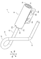
- FIG. 1 shows a side view of the hammer drill of a 1st embodiment, and shows the state where a hook main part was stored.
- FIG. 2 shows a state in which the hook body is pulled out in the hammer drill of FIG. 1.
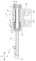
- FIG. 6 is a sectional view taken along line VII-VII of FIG.
- FIG. 7 shows a state in which the hook body is pulled out in the hook of FIG. 6.
- FIG. 9 shows a side view of the hammer drill of a 2nd embodiment, and shows the state where a hook main part was stored.
- Rear view of the hammer drill in FIG. 9 XI-XI sectional view of FIG. Overall perspective view of a conventional strap
- the hammer drill 1 has a main body housing 10, a motor housing 11, a hand grip 14, and a battery mounting part 15.
- the main body housing 10 forms an outer shell of the hammer drill 1.
- the motor housing 11 is assembled below the main body housing 10.
- the hand grip 14 is attached rearward so as to straddle the main body housing 10 and the motor housing 11.
- the battery mounting part 15 is assembled downward so as to straddle the motor housing 11 and the hand grip 14.
- a striking mechanism (not shown) and a rotating mechanism (not shown) are assembled inside the main body housing 10.
- the striking mechanism converts a rotational force of an output shaft (not shown) of a motor (not shown) into a striking force for the drill bit 16.
- the rotation mechanism converts the torque of the output shaft of the motor into a torque for the drill bit 16.
- a motor (not shown) is mounted inside the motor housing 11 so that an output shaft (not shown) faces upward.
- the hand grip 14 is formed with a grip portion 12 that can be gripped by an operator.
- a trigger 17 that turns on an internal switch (not shown) when a worker performs a pulling operation is attached to the hand grip 14.
- Two battery packs 18 serving as power sources are mounted on the battery mounting section 15 side by side along the front and rear. Further, two screw holes (not shown) for attaching hooks 2 described later are formed in the battery mounting portion 15.
- the hook 2 has a hook body 20, a hook support section 30, and an impact absorbing section.
- the hook support 30 supports the hook main body 20 rotatably.
- the shock absorbing portion is interposed between the hook main body 20 and the hook supporting portion 30 and compresses to absorb a shock.
- the shock absorbing part of the present embodiment is an elastic member. More specifically, the shock absorbing portion of the present embodiment includes a rubber 35 and a compression spring 40 (see FIGS. 5 and 6).
- the first hook portion 21, the second hook portion 22, and the straight portion 23 are formed by bending a single wire (metal wire).
- the first hook 21 is substantially L-shaped.
- the first hook portion 21 is formed on the tip end side of the hook body 20.
- the second hook 22 is substantially ring-shaped.
- the second hook portion 22 is formed so as to project outward in a substantially intermediate region (substantially intermediate portion) between the distal end side and the proximal end side of the hook body 20.
- a first spring pin 25 can be inserted into the base end side of the straight portion 23 (see FIG. 6).
- a second spring pin (convex portion) 26 can be inserted into a substantially intermediate region between the distal end side and the proximal end side of the linear portion 23.
- the hook support 30 is a substantially cylindrical member.
- the hook support 30 has an opening 31 at one end and a wall 32 at the other end.
- the hook 32 is closed by the wall 32.
- An attachment portion 30a having two insertion holes 30b into which screws 50 can be inserted is formed in the hook support portion 30.
- the wall 32 has a through hole 32a into which the hook body 20 can be inserted.
- a V-shaped (inclined) first notch groove (recess) 32b and a V-shaped (inclination) second notch groove (recess) 32c are formed on the outer surface of the wall 32. You.
- the first notch groove 32b extends in the up-down direction.
- the second notch groove 32c extends in the left-right direction. Therefore, as shown in FIG. 7, the first notch groove 32b is orthogonal to the second notch groove 32c.
- the rubber 35, the washer 36, and the compression spring 40 are sequentially inserted into the inside 33 of the hook support 30 from the opening 31.
- the base end side of the linear portion 23 is inserted in the order of the through hole 32 a, the rubber 35, the washer 36, and the compression spring 40, and the linear portion 23 is protruded from the opening 31.
- the spring fastening portion 24 is inserted into the base end side of the protruding straight portion 23.
- the first spring pin 25 is inserted so that the inserted spring fastening portion 24 and the base end of the linear portion 23 are fixed.
- the straight portion 23 is pulled out of the hook support portion 30 against the urging force of the compression spring 40, and the second spring pin 26 is inserted into the drawn straight portion 23.
- the pull-out of the linear portion 23 is canceled, and the second spring pin 26 is fitted into the second cutout groove 32c.
- the hook 2 is assembled by such a procedure.
- the hook body 20 of the hook 2 attached in this manner is in a housed state (housed state) (see FIGS. 1 to 2 and FIG. 6). Therefore, when hooking one end of the string member on the hook body 20, it is necessary to switch the hook body 20 to the pulled-out state (usable state). In this case, first, the hook main body 20 is rotated around the axis of the hook main body 20 with respect to the hook support portion 30.
- the second spring pin 26 of the linear portion 23 runs up the inclined surface of the second cutout groove 32c against the urging force of the compression spring 40 and rides on the general portion 32d. Further, the hook main body 20 is turned around the axis with respect to the hook support portion 30. Then, the second spring pin 26 of the rotated linear portion 23 is fitted into the first cutout groove 32 b of the hook support 30 by the urging force of the compression spring 40. As a result, the hook body 20 can be switched to the pulled-out state (see FIGS. 3 to 4 and FIG. 8).
- the hook body 20 In order to return the hook body 20 in the pulled-out state to the housed state, in the above-described switching operation, the hook body 20 is rotated around the axis of the hook body 20 in the opposite direction with respect to the hook support portion 30. Good.
- the function and effect of the hook 2 will be described.
- one end of the string member is passed through the second hook portion 22 of the hook 2 attached to the hammer drill 1 and then the string member is moved. Both ends can be fixed to the hook of the workplace at a high place. That is, the second hook portion 22 of the hook 2 attached to the hammer drill 1 can be connected to the hook portion of the high work place via the string member.
- an impact load is applied to the hook body 20 in a direction away from the hook support portion 30, but the impact load can be absorbed because the rubber 35 and the compression spring 40 are compressed. That is, it can withstand an impact load when it is suspended. Therefore, breakage of the hook support portion 30 of the hook 2 and / or the battery mounting portion 15 of the hammer drill 1 can be prevented.
- the hook 2 is attached to the battery mounting portion 15 so that the axis X of the rubber 35 and the compression spring 40 passes through the center of gravity Y of the hammer drill 1 in a side view of the hammer drill 1 (see FIGS. 1 and 6). ). Therefore, the impact load when the hammer drill 1 is suspended can be smoothly absorbed.
- the hook 2 is attached to the battery mounting portion 15 of the hammer drill 1 of the first embodiment.
- the hook 2 absorbs an impact applied to the hook body 20 between the hook body 20, the hook support 30 supporting the hook body 20, and the hook support 20 by using compression. It has a shock absorbing portion (rubber 35 and compression spring 40). Therefore, the operation and effect of the hook 2 described above can be obtained. That is, the hammer drill 1 can withstand an impact load when it is suspended. Therefore, breakage of the hook support portion 30 of the hook 2 and / or the battery mounting portion 15 of the hammer drill 1 can be prevented.
- the hook support 30 of the present embodiment is detachable from the battery mounting unit 15. Therefore, the hook 2 can be retrofitted to the hammer drill 1. Therefore, the hammer drill 1 is classified into two types, a specification in which the hook 2 is attached before the hammer drill 1 is sold, and a specification in which the hook 2 can be attached (post-installed) after the hammer drill 1 is sold.
- the hook 2 of the present embodiment includes a hook body 20, a hook support portion 30 for supporting the hook body 20, and an impact which is interposed between the hook body 20 and the hook support portion 30 to compress and absorb the impact. It has an absorbing portion (rubber 35 and compression spring 40). Therefore, the operation and effect of the hook 2 described above can be obtained.
- the shock absorbing portion of the present embodiment is formed of an elastic member. Therefore, a simple material can withstand an impact load.
- the elastic member of the present embodiment is composed of the rubber 35 and the compression spring 40. Therefore, even if the compression spring 40 is fully compressed, the impact can be continuously absorbed by the rubber 35 while the compression spring 40 absorbs the impact. Therefore, the impact can be reliably absorbed.
- the hook body 20 of the present embodiment is rotatable with respect to the hook support 30.
- the hook main body 20 is rotated around the axis with respect to the hook support portion 30, the second spring pin 26 of the rotated linear portion 23 is pressed by the first notch groove 32b by the urging force of the compression spring 40. Fit in.
- the hook main body 20 can be switched to the pulled-out state.
- the switching of the hook main body 20 can have a sense of moderation.
- the hook body 20 of the present embodiment has a first hook 21 and a second hook 22 having a different shape from the first hook 21. Therefore, the first hook portion 21 and the second hook portion 22 can be selectively used according to the shape of the hook portion on which the hook body 20 is hooked.
- the first hook 21 is substantially L-shaped
- the second hook 22 is substantially ring-shaped. If the mating member with which the hook body 20 is hooked is a stepladder, it is preferable to use the first hooking portion 21. Further, if the mating member on which the hook body 20 is hooked is a string member or a carbiner, it is preferable to use the second hook portion 22.
- the first hook 21 and the second hook 22 of the present embodiment are formed by bending a single wire. Therefore, the first hook 21 and the second hook 22 can be easily provided.
- the hammer drill 101 according to the second embodiment has a simplified shape of the hook 102 to be attached, as compared with the hammer drill 1 according to the first embodiment.
- members having the same or equivalent configurations as the members described in the first embodiment will be denoted by the same reference numerals in the drawings, and redundant description will be omitted.
- the hook 102 has a hook body 20, a hook support 30, and an impact absorbing part.
- the hook support 30 supports the hook main body 20 rotatably.
- the shock absorbing portion compresses between the hook body 20 and the hook supporting portion 30 to absorb a shock.
- the shock absorbing part of the present embodiment is an elastic member. More specifically, the shock absorbing portion of the present embodiment includes rubber 35 and a compression spring 40.
- the hook support portion 30 of the second embodiment is configured by a substantially semicircular member (see FIG. 11). Therefore, the remaining substantially semicircular portion is formed in the battery mounting portion 15.
- the hook support section 30 is assembled to the battery mounting section 15.
- the hammer drill 101 of the second embodiment has the same function and effect as the hammer drill 1 of the first embodiment. Further, the configuration of the hook support portion 30 of the second embodiment can be more simplified than that of the first embodiment.
- the hammer drills 1 and 101 in each embodiment are not limited to the above-described embodiments, and may be appropriately changed as follows.
- the elastic member is not limited to the combination of the compression spring 40 and the rubber 35, and may be the compression spring 40 alone or the rubber 35 alone.
- the elastic member may be a single product such as various types of mechanical springs, disc springs, urethane, or the like, or an arbitrary combination thereof.
- each embodiment may be formed such that the second hooking portion 22 projects inward in a substantially intermediate region between the distal end side and the proximal end side of the hook body 20.
- the positional relationship between the first hooking portion 21 and the second hooking portion 22 may be reversed. That is, the second hook portion 22 may be formed on the distal end side of the hook main body 20, and the first hook portion 21 may be formed in a substantially intermediate region between the distal end side and the base end side of the hook main body 20.
- compression by the elastic member has been described, but compression by air, gas, liquid, or the like may be used.
- the hammer drill 1 is illustrated as an example of the power tool, but various power tools, various air tools, various engine tools, and the like may be used.
- the second spring pin 26 is provided on the straight portion 23, and the first cutout groove 32 b, the second cutout groove 32 c, and the general portion 32 d are provided on the wall 32 of the hook support 30.
- the form has been described.
- the first notch groove 32b, the second notch groove 32c, and the general portion 32d are provided in the linear portion 23 of the hook body 20, and the convex portion is formed so as to correspond to the second spring pin 26. It may be provided on the wall 32 of the hook support 30.
Landscapes
- Engineering & Computer Science (AREA)
- Mechanical Engineering (AREA)
- Percussive Tools And Related Accessories (AREA)
- Workshop Equipment, Work Benches, Supports, Or Storage Means (AREA)
- Portable Power Tools In General (AREA)
Abstract
吊り下げられた状態になったときの衝撃荷重に耐えられる動力工具およびフックを提供する。 フック本体20と、フック本体20を支持するフック支持部30と、フック本体20とフック支持部30との間に配置される圧縮可能な衝撃吸収部35、40であって、フック本体20に付加される衝撃吸収する衝撃吸収部35、40と、を有するフック2。
Description
本発明は、動力工具およびフックに関する。
従来、高所作業における動力工具に、様々な落下防止対策が施されている。ここで、米国特許出願公開第2017/0119137号明細書(以下、「特許文献1」)には、引っ張りばね240を有し、ループ状を成すように動力工具本体(不図示、グラインダ本体)のハウジング(不図示)に対して取り付け可能なストラップ202が開示されている(図12参照)。これにより、紐部材(不図示、ロープまたはワイヤー)の一端を動力工具本体に取り付けたストラップ202のループに通した後に、紐部材の両端を高所作業場(手すりまたは足場等)の引掛部(不図示)に固定できる。すなわち、動力工具本体に取り付けたストラップ202と高所作業場の引掛部とを紐部材を介して繋げることができる。そのため、例えば、手に持った動力工具本体を誤って落下させた場合でも、動力工具本体が紐部材を介して高所作業場の引掛部に吊り下げられた状態となる。したがって、動力工具本体が地面(地上)まで落下することを防止できる。
しかしながら、特許文献1の技術では、落下させた動力工具が紐部材を介して高所作業場の引掛部に吊り下げられた際の衝撃荷重によって、動力工具本体のハウジングに対するストラップ202の取付部230および/または動力工具本体のハウジングが破損することがある。
本発明は、吊り下げられた状態になったときの衝撃荷重に耐えられる動力工具およびフックを提供することを目的とする。
本発明の第1の観点は、
フック本体と、
前記フック本体を支持するフック支持部と、
前記フック本体と前記フック支持部との間に配置される圧縮可能な衝撃吸収部であって、前記フック本体に付加される衝撃吸収する衝撃吸収部と、
を有するフックである。
フック本体と、
前記フック本体を支持するフック支持部と、
前記フック本体と前記フック支持部との間に配置される圧縮可能な衝撃吸収部であって、前記フック本体に付加される衝撃吸収する衝撃吸収部と、
を有するフックである。
本発明の第2の観点は、
動力工具本体であって、
本体ハウジングと、
前記本体ハウジングの下方に組み付けられるモータハウジングと、
前記本体ハウジングと前記モータハウジングとを跨ぐように後方に組み付けられるハンドグリップと、
前記モータハウジングと前記ハンドグリップとを跨ぐように下方に組み付けられるバッテリ装着部と、
を有する動力工具本体と、
前記動力工具本体に対して着脱可能なフックであって、
フック本体と、
前記フック本体を支持するフック支持部と、
前記フック本体と前記フック支持部との間に配置される圧縮可能な衝撃吸収部であって、前記フック本体に付加される衝撃吸収する衝撃吸収部と、
を有するフックと、
を有する、動力工具である。
動力工具本体であって、
本体ハウジングと、
前記本体ハウジングの下方に組み付けられるモータハウジングと、
前記本体ハウジングと前記モータハウジングとを跨ぐように後方に組み付けられるハンドグリップと、
前記モータハウジングと前記ハンドグリップとを跨ぐように下方に組み付けられるバッテリ装着部と、
を有する動力工具本体と、
前記動力工具本体に対して着脱可能なフックであって、
フック本体と、
前記フック本体を支持するフック支持部と、
前記フック本体と前記フック支持部との間に配置される圧縮可能な衝撃吸収部であって、前記フック本体に付加される衝撃吸収する衝撃吸収部と、
を有するフックと、
を有する、動力工具である。
(第1実施形態)
以下、本発明を実施するための形態を、図面を用いて説明する。まず、第1実施形態を、図1~図8を用いて説明する。なお、以下の説明にあたって、動力工具の一例として、ハンマードリル1を例示する。また、以下の説明にあたって、上、下、前、後、左、右とは、上述した図に記載した、上、下、前、後、左、右の方向を示す。すなわち、前の方向が、ハンマードリル1の先端方向(ドリルビット16が延びる方向)を示す。後述する第2実施形態においても同様である。
以下、本発明を実施するための形態を、図面を用いて説明する。まず、第1実施形態を、図1~図8を用いて説明する。なお、以下の説明にあたって、動力工具の一例として、ハンマードリル1を例示する。また、以下の説明にあたって、上、下、前、後、左、右とは、上述した図に記載した、上、下、前、後、左、右の方向を示す。すなわち、前の方向が、ハンマードリル1の先端方向(ドリルビット16が延びる方向)を示す。後述する第2実施形態においても同様である。
はじめに、ハンマードリル1と、ハンマードリル1のバッテリ装着部15に取り付けられるフック2とを個別に説明する。
最初に、ハンマードリル1から説明する(図1~図4参照)。ハンマードリル1は、本体ハウジング10と、モータハウジング11と、ハンドグリップ14と、バッテリ装着部15とを有する。本体ハウジング10は、ハンマードリル1の外郭を成す。モータハウジング11は、本体ハウジング10の下方に組み付けられる。ハンドグリップ14は、本体ハウジング10とモータハウジング11とを跨ぐように後方に組み付けられる。バッテリ装着部15は、モータハウジング11とハンドグリップ14とを跨ぐように下方に組み付けられる。
本体ハウジング10の内部には、打撃機構(不図示)と、回転機構(不図示)とが組み付けられる。打撃機構は、モータ(不図示)の出力軸(不図示)の回転力を、ドリルビット16に対する打撃力に変換する。回転機構は、モータの出力軸の回転力を、ドリルビット16に対する回転力に変換する。
モータハウジング11の内部には、出力軸(不図示)が上を向くようにモータ(不図示)が組み付けられる。
モータハウジング11の内部には、出力軸(不図示)が上を向くようにモータ(不図示)が組み付けられる。
ハンドグリップ14には、作業者が握り可能な握り部12が形成される。また、ハンドグリップ14には、作業者が引き操作をすると、内部スイッチ(不図示)がONするトリガ17が組み付けられる。
バッテリ装着部15には、電源となる2個のバッテリパック18が前後に沿って並んで装着される。また、バッテリ装着部15には、後述するフック2を取り付けるための2個のビス孔(不図示)が形成される。
バッテリ装着部15には、電源となる2個のバッテリパック18が前後に沿って並んで装着される。また、バッテリ装着部15には、後述するフック2を取り付けるための2個のビス孔(不図示)が形成される。
作業者が握り部12を握った状態でトリガ17を引き操作すると、引き操作にともなって動作する内部スイッチから電気的な信号がモータハウジング11の内部に組み付けられたコントローラ(不図示)に入力される。これにより、モータの出力軸が回転し、モータの出力軸の回転力が打撃機構を介してドリルビット16に対する打撃力に変換され伝達される。このように、ドリルビット16の打撃動作を実施できる。
これと同時に、モータの出力軸の回転力が回転機構を介してドリルビット16に対する回転力に変換され伝達される。このように、ドリルビット16の回転動作を実施できる。したがって、ドリルビット16に対して打撃力と回転力を付与できるため、石こう材等の穴開け作業を効率よく実施できる。
次に、フック2を説明する(図5~図8参照)。フック2は、フック本体20と、フック支持部30と、衝撃吸収部とを有する。フック支持部30は、フック本体20を回動可能に支持する。衝撃吸収部は、フック本体20とフック支持部30との間に介在されて、圧縮して衝撃を吸収する。本実施形態の衝撃吸収部は、弾性部材である。具体的には、本実施形態の衝撃吸収部は、ゴム35と圧縮ばね40で構成される(図5~図6参照)。
フック本体20は、第1の引掛部21と、第2の引掛部22と、直線部23とが、単一の線材(金属線材)の曲げ加工によって形成される。第1の引掛部21は、略L字状である。第1の引掛部21は、フック本体20の先端側に形成される。第2の引掛部22は、略リング状である。第2の引掛部22は、フック本体20の先端側と基端側との略中間領域(略中間部)に、外側に向けて張り出すように形成される。直線部23の基端側には、第1のスプリングピン25が挿し込み可能である(図6参照)。直線部23の先端側と基端側との略中間領域には、第2のスプリングピン(凸部)26が挿し込み可能である。
フック支持部30は、略円筒部材である。フック支持部30は、一端に開口31を有し、他端に壁体32を有する。壁体32によって、フック支持部30が塞がれる。フック支持部30には、ビス50を挿し込み可能な2個の挿通孔30bを有する取付部30aが形成される。壁体32には、フック本体20を挿し込み可能な貫通孔32aが形成される。また、壁体32の外面には、V字状(傾斜状)の第1の切欠溝(凹部)32bと、V字状(傾斜状)の第2の切欠溝(凹部)32cとが形成される。第1の切欠溝32bは、上下方向に延びる。第2の切欠溝32cは、左右方向に延びる。そのため、図7に示すように、第1の切欠溝32bと第2の切欠溝32cは直交する。
次に、フック2の組み立ての手順の一例を説明する。まず、フック支持部30の内部33に開口31から、ゴム35とワッシャ36と圧縮ばね40とを順に入れ込む。次に、直線部23の基端側を貫通孔32aとゴム35とワッシャ36と圧縮ばね40の順に挿し込み、開口31から直線部23を突き出す。次に、突き出した直線部23の基端側にばね留め部24を挿し込む。
次に、挿し込んだばね留め部24と直線部23の基端側とが固着されるように、第1のスプリングピン25を挿し込む。次に、圧縮ばね40の付勢力に抗してフック支持部30から直線部23を引き出し、引き出した直線部23に第2のスプリングピン26を挿し込む。最後に、直線部23の引き出しを解消し、第2のスプリングピン26を第2の切欠溝32cに嵌め込む。このような手順によって、フック2が組み立てられる。
なお、組み立てられたフック2の2個の挿通孔30bには、2個のビス50が挿し込まれ、挿し込まれた2個のビス50は、バッテリ装着部15の2個のビス孔19に螺合される。このようにして、バッテリ装着部15にフック2を取り付けることができる。すなわち、フック2のフック支持部30は、ハンマードリル1のバッテリ装着部15に対して着脱可能である。
このように取り付けられたフック2のフック本体20は、収納された状態(収納状態)となる(図1~図2、図6参照)。そのため、フック本体20に紐部材の一端を引っ掛けるとき、フック本体20を引き出し状態(使用可能状態)に切り替える必要がある。その場合、まず、フック本体20をフック支持部30に対してフック本体20の軸回りに回動させる。
すると、直線部23の第2のスプリングピン26が、圧縮ばね40の付勢力に抗して第2の切欠溝32cの傾斜面を駆け上がり、一般部32dに乗り上げる。さらに、フック本体20をフック支持部30に対して軸回りに回動させる。すると、回動させた直線部23の第2のスプリングピン26が、圧縮ばね40の付勢力によってフック支持部30の第1の切欠溝32bに嵌り込む。これにより、フック本体20を引き出し状態に切り替えることができる(図3~図4、図8参照)。
なお、引き出し状態のフック本体20を収納状態に戻すためには、上述した切り替えの作業において、フック本体20をフック支持部30に対してフック本体20の軸回りに逆向きに回動させればよい。
続いて、フック2の作用効果を説明する。従来技術の説明と同様に、高所作業におけるハンマードリル1の落下防止の対策として、紐部材の一端をハンマードリル1に取り付けたフック2の第2の引掛部22に通した後に、紐部材の両端を高所作業場の引掛部に固定できる。すなわち、ハンマードリル1に取り付けたフック2の第2の引掛部22と高所作業場の引掛部とを、紐部材を介して繋げることができる。
そのため、例えば、手に持ったハンマードリル1を誤って落下させた場合でも、ハンマードリル1が紐部材を介して高所作業場の引掛部に吊り下げられる。したがって、ハンマードリル1が地面(地上)まで落下することを防止できる。なお、落下させたハンマードリル1が紐部材を介して高所作業場の引掛部に吊り下げられると、フック支持部30に対してフック本体20が引き出される。
このとき、フック本体20にはフック支持部30から離間する方向の衝撃荷重が付加されるが、ゴム35と圧縮ばね40とが圧縮されるため、衝撃荷重を吸収できる。すなわち、吊り下げられた状態になったときの衝撃荷重に耐えられる。したがって、フック2のフック支持部30および/またはハンマードリル1のバッテリ装着部15の破損を防止できる。また、ハンマードリル1の側面視において、ゴム35と圧縮ばね40との軸芯Xがハンマードリル1の重心Yを通るように、フック2はバッテリ装着部15に取り付けられる(図1、図6参照)。そのため、ハンマードリル1が吊り下げられた状態になったときの衝撃荷重をスムーズに吸収できる。
第1実施形態のハンマードリル1のバッテリ装着部15には、フック2が取り付けられる。フック2は、フック本体20と、フック本体20を支持するフック支持部30と、フック本体20とフック支持部30との間に、フック本体20に付加される衝撃を圧縮を利用して吸収する衝撃吸収部(ゴム35と圧縮ばね40)とを有する。そのため、上述したフック2の作用効果が得られる。すなわち、ハンマードリル1が吊り下げられた状態になったときの衝撃荷重に耐えられる。したがって、フック2のフック支持部30および/またはハンマードリル1のバッテリ装着部15の破損を防止できる。
また、本実施形態のフック支持部30は、バッテリ装着部15に対して着脱可能である。そのため、ハンマードリル1に対してフック2を後付けできる。したがって、ハンマードリル1の販売前に、予め、フック2を取り付けてた仕様と、ハンマードリル1の販売後にフック2を取り付け(後付け)可能な仕様の、2種類の仕様に分けられる。
また、本実施形態のフック2は、フック本体20と、フック本体20を支持するフック支持部30と、フック本体20とフック支持部30との間に介在されて圧縮して衝撃を吸収する衝撃吸収部(ゴム35と圧縮ばね40)とを有する。そのため、上述したフック2の作用効果が得られる。
また、本実施形態の衝撃吸収部は、弾性部材から構成される。そのため、簡便な素材で衝撃荷重に耐えられる。
また、本実施形態の弾性部材は、ゴム35と圧縮ばね40とから構成される。そのため、圧縮ばね40が衝撃を吸収しつつ、仮に、圧縮ばね40が全圧縮状態になっても、引き続き、ゴム35で衝撃を吸収できる。したがって、確実に衝撃を吸収できる。
また、本実施形態のフック本体20は、フック支持部30に対して回動可能である。また、フック本体20をフック支持部30に対して軸回りに回動させると、回動させた直線部23の第2のスプリングピン26が、圧縮ばね40の付勢力によって第1の切欠溝32bに嵌り込む。これにより、フック本体20を引き出し状態に切り替えられる。切り替えたフック本体20を収納状態に戻すときも同様である。そのため、フック本体20の切り替えに節度感を持たすことができる。
また、本実施形態のフック本体20は、第1の引掛部21と、第1の引掛部21と異なる形状の第2の引掛部22とを有する。そのため、フック本体20を引っ掛ける相手となる引掛部の形状に合わせて、第1の引掛部21と第2の引掛部22とを使い分けできる。例えば、第1の引掛部21は略L字状であり、第2の引掛部22は略リング状である。フック本体20を引っ掛ける相手となる相手部材が脚立であれば、第1の引掛部21を使用することが好ましい。また、フック本体20を引っ掛ける相手となる相手部材が紐部材やカルビナであれば、第2の引掛部22を使用することが好ましい。
また、本実施形態の第1の引掛部21と第2の引掛部22とは、単一の線材の曲げ加工により形成される。そのため、第1の引掛部21と第2の引掛部22とを簡便に設けられる。
(第2実施形態)
次に、第2実施形態を、図9~図11を用いて説明する。第2実施形態のハンマードリル101は、第1実施形態のハンマードリル1と比較すると、取り付けられるフック102の形状を簡素化したものである。なお、以下の説明にあたって、第1実施形態で説明した部材と同一または均等な構成の部材には、図面において同一の符号を付すことで重複する説明は省略する。
次に、第2実施形態を、図9~図11を用いて説明する。第2実施形態のハンマードリル101は、第1実施形態のハンマードリル1と比較すると、取り付けられるフック102の形状を簡素化したものである。なお、以下の説明にあたって、第1実施形態で説明した部材と同一または均等な構成の部材には、図面において同一の符号を付すことで重複する説明は省略する。
フック102は、フック本体20と、フック支持部30と、衝撃吸収部とを有する。フック支持部30は、フック本体20を回動可能に支持する。衝撃吸収部は、フック本体20とフック支持部30との間で圧縮して、衝撃を吸収する。本実施形態の衝撃吸収部は、弾性部材である。具体的には、本実施形態の衝撃吸収部は、ゴム35と圧縮ばね40で構成される。なお、第2実施形態のフック支持部30は、第1実施形態とは異なり、略半円部材で構成される(図11参照)。そのため、残りの略半円部分は、バッテリ装着部15に形成される。フック支持部30は、バッテリ装着部15に組み付けられる。
第2実施形態のハンマードリル101は、第1実施形態のハンマードリル1と同様の作用効果を奏する。また、第2実施形態のフック支持部30の構成は、第1実施形態より簡素化できる。
なお、各実施形態のハンマードリル1、101は、上記した実施形態に限定されるものではなく、次のように適宜個所を変更してもよい。例えば、弾性部材は、圧縮ばね40とゴム35との組み合わせに限定されることなく、圧縮ばね40のみでも構わないし、ゴム35のみでも構わない。また、弾性部材は、各種の機械ばね、皿ばね、ウレタン等の単品またはこれらの任意の組み合わせでも構わない。
また、各実施形態のフック2、102は、第2の引掛部22がフック本体20の先端側と基端側との略中間領域に内側に向けて張り出すように形成されても構わない。また、第1の引掛部21と第2の引掛部22との位置関係が逆でも構わない。すなわち、第2の引掛部22がフック本体20の先端側に形成され、第1の引掛部21がフック本体20の先端側と基端側との略中間領域に形成されても構わない。
また、各実施形態では、弾性部材による圧縮を説明したが、エア、気体、液体等による圧縮でも構わない。また、各実施形態では、動力工具の一例として、ハンマードリル1を例示したが、各種の電動工具、各種のエア工具、各種のエンジン工具等でも構わない。
また、各実施形態では、第2のスプリングピン26は直線部23に設けられ、第1の切欠溝32b、第2の切欠溝32cおよび一般部32dはフック支持部30の壁体32に設けられる形態を説明した。しかし、これとは逆に、第1の切欠溝32b、第2の切欠溝32cおよび一般部32dをフック本体20の直線部23に設け、第2のスプリングピン26に相当するように凸部をフック支持部30の壁体32に設けても構わない。
1 ハンマードリル(動力工具)
2 フック
10 本体ハウジング
11 モータハウジング
12 握り部
14 ハンドグリップ
15 バッテリ装着部
16 ドリルビット
17 トリガ
18 バッテリパック
19 ビス孔
20 フック本体
21 第1の引掛部
22 第2の引掛部
23 直線部
24 ばね留め部
25 第1のスプリングピン
26 第2のスプリングピン
30 フック支持部
30a 取付部
30b 挿通孔
31 開口
32 壁体
32a 貫通孔
32b 第1の切欠溝
32c 第2の切欠溝
33 内部
35 ゴム(衝撃吸収部、弾性部材)
36 ワッシャ
40 圧縮ばね(衝撃吸収部、弾性部材)
50 ビス
X 軸芯
Y 重心
2 フック
10 本体ハウジング
11 モータハウジング
12 握り部
14 ハンドグリップ
15 バッテリ装着部
16 ドリルビット
17 トリガ
18 バッテリパック
19 ビス孔
20 フック本体
21 第1の引掛部
22 第2の引掛部
23 直線部
24 ばね留め部
25 第1のスプリングピン
26 第2のスプリングピン
30 フック支持部
30a 取付部
30b 挿通孔
31 開口
32 壁体
32a 貫通孔
32b 第1の切欠溝
32c 第2の切欠溝
33 内部
35 ゴム(衝撃吸収部、弾性部材)
36 ワッシャ
40 圧縮ばね(衝撃吸収部、弾性部材)
50 ビス
X 軸芯
Y 重心
Claims (11)
- フック本体と、
前記フック本体を支持するフック支持部と、
前記フック本体と前記フック支持部との間に配置される圧縮可能な衝撃吸収部であって、前記フック本体に付加される衝撃吸収する衝撃吸収部と、
を有するフック。 - 前記衝撃吸収部は、弾性部材である、
請求項1に記載のフック。 - 前記弾性部材は、ゴムと、圧縮ばねと、を有する、
請求項2に記載のフック。 - 前記フック支持部は、複数の凹部を有する壁部を有し、
前記フック本体は、前記弾性部材の付勢力によって、前記複数の凹部に嵌め込み可能な凸部を有し、
前記フック本体は、前記フック支持部に対して回動可能であり、前記複数の凹部のいずれかにより回動方向を位置決め可能である、
請求項2又は3に記載のフック。 - 前記フック本体は、複数の凹部を有し、
前記フック支持部は、前記弾性部材の付勢力によって、前記複数の凹部に嵌め込み可能な凸部を有し、
前記フック本体は、前記フック支持部に対して回動可能であり、前記複数の凹部のいずれかにより回動方向を位置決め可能である、
請求項2又は3に記載のフック。 - 前記フック本体は、第1の引掛部と、前記第1の引掛部と異なる形状の第2の引掛部と、を有する
請求項1~5のいずれかに記載のフック。 - 前記第1の引掛部と、前記第2の引掛部とは、単一の線材の曲げ加工により形成されている
請求項6に記載のフック。 - 前記フック支持部は、ビスを挿し込み可能な挿通孔を有する取付部を有する、
請求項1~7のいずれかに記載のフック。 - 動力工具本体であって、
本体ハウジングと、
前記本体ハウジングの下方に組み付けられるモータハウジングと、
前記本体ハウジングと前記モータハウジングとを跨ぐように後方に組み付けられるハンドグリップと、
前記モータハウジングと前記ハンドグリップとを跨ぐように下方に組み付けられるバッテリ装着部と、
を有する動力工具本体と、
前記動力工具本体に対して着脱可能なフックであって、
フック本体と、
前記フック本体を支持するフック支持部と、
前記フック本体と前記フック支持部との間に配置される圧縮可能な衝撃吸収部であって、前記フック本体に付加される衝撃吸収する衝撃吸収部と、
を有するフックと、
を有する、動力工具。 - 前記取付部は、前記バッテリ装着部に着脱可能である、
請求項9に記載の動力工具。 - 前記フック支持部は、断面略半円形状を有し、
前記バッテリ装着部は、前記フック支持部を組み付けられるように、断面略半円形状を有する
請求項9又は10に記載の動力工具。
Priority Applications (3)
| Application Number | Priority Date | Filing Date | Title |
|---|---|---|---|
| DE112019003879.6T DE112019003879T5 (de) | 2018-10-05 | 2019-08-06 | Kraftwerkzeug und Haken |
| CN201980055030.3A CN112584979A (zh) | 2018-10-05 | 2019-08-06 | 动力工具和钩 |
| US17/270,088 US11772254B2 (en) | 2018-10-05 | 2019-08-06 | Power tool and hook |
Applications Claiming Priority (2)
| Application Number | Priority Date | Filing Date | Title |
|---|---|---|---|
| JP2018-189891 | 2018-10-05 | ||
| JP2018189891A JP7237509B2 (ja) | 2018-10-05 | 2018-10-05 | 動力工具およびフック |
Publications (1)
| Publication Number | Publication Date |
|---|---|
| WO2020070972A1 true WO2020070972A1 (ja) | 2020-04-09 |
Family
ID=70055720
Family Applications (1)
| Application Number | Title | Priority Date | Filing Date |
|---|---|---|---|
| PCT/JP2019/031001 Ceased WO2020070972A1 (ja) | 2018-10-05 | 2019-08-06 | 動力工具およびフック |
Country Status (5)
| Country | Link |
|---|---|
| US (1) | US11772254B2 (ja) |
| JP (1) | JP7237509B2 (ja) |
| CN (1) | CN112584979A (ja) |
| DE (1) | DE112019003879T5 (ja) |
| WO (1) | WO2020070972A1 (ja) |
Families Citing this family (7)
| Publication number | Priority date | Publication date | Assignee | Title |
|---|---|---|---|---|
| JP7337530B2 (ja) * | 2019-04-05 | 2023-09-04 | 株式会社マキタ | 動力工具および工具保持具 |
| CN114683218B (zh) * | 2020-12-29 | 2025-08-29 | 喜利得股份公司 | 用于动力工具的挂钩组件 |
| CN215470913U (zh) * | 2021-05-21 | 2022-01-11 | 浙江普莱得电器股份有限公司 | 一种伸缩悬挂组件 |
| DE102021209180A1 (de) | 2021-08-20 | 2023-02-23 | Robert Bosch Gesellschaft mit beschränkter Haftung | Handgehaltenes Bearbeitungsgerät mit einer Aufhängevorrichtung |
| US12611761B2 (en) | 2021-11-24 | 2026-04-28 | Milwaukee Electric Tool Corporation | Grinder including enhanced sensing and component detection |
| USD1034128S1 (en) * | 2022-02-07 | 2024-07-09 | Robert Bosch Gmbh | Hammer drill |
| US12466049B2 (en) | 2022-11-15 | 2025-11-11 | Milwaukee Electric Tool Corporation | Power tool with tether |
Citations (7)
| Publication number | Priority date | Publication date | Assignee | Title |
|---|---|---|---|---|
| JPS5484900U (ja) * | 1977-11-29 | 1979-06-15 | ||
| JPS58120587U (ja) * | 1982-02-12 | 1983-08-17 | 株式会社小糸製作所 | ソケツト |
| JPS5987351U (ja) * | 1982-12-03 | 1984-06-13 | トヨタ自動車株式会社 | エンジンの吊り具構造 |
| JP2006326753A (ja) * | 2005-05-26 | 2006-12-07 | Makita Corp | 携帯工具のフック |
| JP2011140110A (ja) * | 2009-12-10 | 2011-07-21 | Makita Corp | 電動工具用フック及び電動工具用フックを取り付けた電動工具 |
| JP2016023447A (ja) * | 2014-07-18 | 2016-02-08 | 安弘 芦田 | シートの折畳み方法、鳩目引掛け具、及び折畳み状態保持具 |
| JP2018058190A (ja) * | 2016-10-07 | 2018-04-12 | 株式会社マキタ | 電動工具 |
Family Cites Families (21)
| Publication number | Priority date | Publication date | Assignee | Title |
|---|---|---|---|---|
| US4787145A (en) * | 1987-03-09 | 1988-11-29 | Klicker Garry L | Two position portable power tool hanger stabilized by spring and detent |
| US5924667A (en) * | 1997-05-01 | 1999-07-20 | Grahn; Craig | Positioning device |
| US5850698A (en) * | 1997-05-30 | 1998-12-22 | Black & Decker Inc. | Portable circular saw |
| US7111364B2 (en) * | 2002-03-28 | 2006-09-26 | Hilti Aktiengesellschaft | Hand-held power tool with a holding device |
| US20040178240A1 (en) * | 2003-03-12 | 2004-09-16 | Bauer Ernest A. | Tool belt tote |
| JP3553589B2 (ja) * | 2003-09-29 | 2004-08-11 | 日立工機株式会社 | 携帯用工具 |
| US7306052B2 (en) * | 2004-10-05 | 2007-12-11 | Illinois Tool Works Inc. | Multi-position utility hook assembly for tool |
| US20080148915A1 (en) | 2006-10-30 | 2008-06-26 | Black & Decker Inc. | Power tools |
| EP2022607B1 (en) * | 2007-07-26 | 2011-03-09 | Makita Corporation | Hook structure of power tool |
| CN201384803Y (zh) * | 2009-03-25 | 2010-01-20 | 安徽省电力公司安庆供电公司 | 电力杆塔上用于防坠的钢索悬吊装置 |
| JP5379625B2 (ja) * | 2009-09-25 | 2013-12-25 | パナソニック株式会社 | 電動工具 |
| JP5410927B2 (ja) * | 2009-11-10 | 2014-02-05 | 株式会社マキタ | 電動工具用フック及び電動工具用フックを取り付けた電動工具 |
| JP5502458B2 (ja) | 2009-12-25 | 2014-05-28 | 株式会社マキタ | 打撃工具 |
| US9522464B2 (en) * | 2011-05-16 | 2016-12-20 | Illinois Tool Works Inc. | Multi-position utility hook assembly for a tool |
| AU2012377385A1 (en) * | 2012-04-18 | 2014-01-23 | Arrowhead Research Corporation | Poly(acrylate) polymers for in vivo nucleic acid delivery |
| CN105899338B (zh) * | 2013-08-06 | 2019-12-03 | 罗伯特·博世有限公司 | 用于动力工具的双轴线钩组件 |
| US10040178B2 (en) * | 2014-05-27 | 2018-08-07 | Makita Corporation | Power tool and rotary impact tool |
| JP6549953B2 (ja) * | 2015-09-18 | 2019-07-24 | 株式会社マキタ | 切断工具 |
| US10045606B2 (en) | 2015-11-02 | 2018-08-14 | Black & Decker Inc. | Impact-absorbing tethering attachment |
| EP3434421A1 (de) * | 2017-07-28 | 2019-01-30 | HILTI Aktiengesellschaft | Hakenhalterung für eine werkzeugmaschine |
| US10058986B1 (en) * | 2018-04-04 | 2018-08-28 | Apex Mfg. Co., Ltd. | Stapler |
-
2018
- 2018-10-05 JP JP2018189891A patent/JP7237509B2/ja active Active
-
2019
- 2019-08-06 DE DE112019003879.6T patent/DE112019003879T5/de active Pending
- 2019-08-06 CN CN201980055030.3A patent/CN112584979A/zh active Pending
- 2019-08-06 WO PCT/JP2019/031001 patent/WO2020070972A1/ja not_active Ceased
- 2019-08-06 US US17/270,088 patent/US11772254B2/en active Active
Patent Citations (7)
| Publication number | Priority date | Publication date | Assignee | Title |
|---|---|---|---|---|
| JPS5484900U (ja) * | 1977-11-29 | 1979-06-15 | ||
| JPS58120587U (ja) * | 1982-02-12 | 1983-08-17 | 株式会社小糸製作所 | ソケツト |
| JPS5987351U (ja) * | 1982-12-03 | 1984-06-13 | トヨタ自動車株式会社 | エンジンの吊り具構造 |
| JP2006326753A (ja) * | 2005-05-26 | 2006-12-07 | Makita Corp | 携帯工具のフック |
| JP2011140110A (ja) * | 2009-12-10 | 2011-07-21 | Makita Corp | 電動工具用フック及び電動工具用フックを取り付けた電動工具 |
| JP2016023447A (ja) * | 2014-07-18 | 2016-02-08 | 安弘 芦田 | シートの折畳み方法、鳩目引掛け具、及び折畳み状態保持具 |
| JP2018058190A (ja) * | 2016-10-07 | 2018-04-12 | 株式会社マキタ | 電動工具 |
Also Published As
| Publication number | Publication date |
|---|---|
| DE112019003879T5 (de) | 2021-04-15 |
| US11772254B2 (en) | 2023-10-03 |
| JP2020059067A (ja) | 2020-04-16 |
| US20210205977A1 (en) | 2021-07-08 |
| CN112584979A (zh) | 2021-03-30 |
| JP7237509B2 (ja) | 2023-03-13 |
Similar Documents
| Publication | Publication Date | Title |
|---|---|---|
| JP7237509B2 (ja) | 動力工具およびフック | |
| JP7337530B2 (ja) | 動力工具および工具保持具 | |
| US7681661B2 (en) | Electric power tool | |
| US8256528B2 (en) | Vibration-damped holder for additional handle | |
| EP2898991B1 (en) | Rear handle | |
| EP2898993B1 (en) | Power tool | |
| JP6612157B2 (ja) | 補助ハンドルおよび作業工具 | |
| EP2898992A1 (en) | Power tool with rear handle, method of manufacturing a part of a handle assembly for a power tool and method of disassembling a part of a handle assembly for a power tool | |
| US20250091189A1 (en) | Vibration damping structure for power tool and power tool with vibration damping structure | |
| JP6831742B2 (ja) | 電動工具 | |
| JP2018153876A (ja) | 電動工具 | |
| KR102208476B1 (ko) | 그라인더 전환용 드릴 어댑터 | |
| JP5029878B2 (ja) | 電動工具 | |
| US7398712B1 (en) | Rotary impact tool | |
| JP5510733B2 (ja) | 手持ち式動力工具 | |
| WO2017090376A1 (ja) | 電気機器 | |
| EP3138661A1 (en) | Work tool | |
| JP2022122765A (ja) | 打撃工具 | |
| JP3553589B2 (ja) | 携帯用工具 | |
| US20140060265A1 (en) | Shock absorbing tool bits | |
| JP2005313322A (ja) | 電動工具 | |
| JP2004090217A (ja) | 携帯用工具 | |
| KR20160117872A (ko) | 전동 공구 |
Legal Events
| Date | Code | Title | Description |
|---|---|---|---|
| 121 | Ep: the epo has been informed by wipo that ep was designated in this application |
Ref document number: 19869843 Country of ref document: EP Kind code of ref document: A1 |
|
| 122 | Ep: pct application non-entry in european phase |
Ref document number: 19869843 Country of ref document: EP Kind code of ref document: A1 |