WO2020070950A1 - ワイヤハーネス、及び外装部材 - Google Patents
ワイヤハーネス、及び外装部材Info
- Publication number
- WO2020070950A1 WO2020070950A1 PCT/JP2019/028286 JP2019028286W WO2020070950A1 WO 2020070950 A1 WO2020070950 A1 WO 2020070950A1 JP 2019028286 W JP2019028286 W JP 2019028286W WO 2020070950 A1 WO2020070950 A1 WO 2020070950A1
- Authority
- WO
- WIPO (PCT)
- Prior art keywords
- exterior member
- wire harness
- wire
- resin pipe
- discharge holes
- Prior art date
- Legal status (The legal status is an assumption and is not a legal conclusion. Google has not performed a legal analysis and makes no representation as to the accuracy of the status listed.)
- Ceased
Links
Images


Classifications
-
- H—ELECTRICITY
- H01—ELECTRIC ELEMENTS
- H01B—CABLES; CONDUCTORS; INSULATORS; SELECTION OF MATERIALS FOR THEIR CONDUCTIVE, INSULATING OR DIELECTRIC PROPERTIES
- H01B7/00—Insulated conductors or cables characterised by their form
- H01B7/17—Protection against damage caused by external factors, e.g. sheaths or armouring
- H01B7/18—Protection against damage caused by wear, mechanical force or pressure; Sheaths; Armouring
- H01B7/1805—Protections not provided for in groups H01B7/182 - H01B7/26
-
- H—ELECTRICITY
- H02—GENERATION; CONVERSION OR DISTRIBUTION OF ELECTRIC POWER
- H02G—INSTALLATION OF ELECTRIC CABLES OR LINES, OR OF COMBINED OPTICAL AND ELECTRIC CABLES OR LINES
- H02G3/00—Installations of electric cables or lines or protective tubing therefor in or on buildings, equivalent structures or vehicles
- H02G3/02—Details
- H02G3/04—Protective tubing or conduits, e.g. cable ladders or cable troughs
- H02G3/0462—Tubings, i.e. having a closed section
- H02G3/0487—Tubings, i.e. having a closed section with a non-circular cross-section
-
- B—PERFORMING OPERATIONS; TRANSPORTING
- B60—VEHICLES IN GENERAL
- B60R—VEHICLES, VEHICLE FITTINGS, OR VEHICLE PARTS, NOT OTHERWISE PROVIDED FOR
- B60R16/00—Electric or fluid circuits specially adapted for vehicles and not otherwise provided for; Arrangement of elements of electric or fluid circuits specially adapted for vehicles and not otherwise provided for
- B60R16/02—Electric or fluid circuits specially adapted for vehicles and not otherwise provided for; Arrangement of elements of electric or fluid circuits specially adapted for vehicles and not otherwise provided for electric constitutive elements
- B60R16/0207—Wire harnesses
- B60R16/0215—Protecting, fastening and routing means therefor
-
- F—MECHANICAL ENGINEERING; LIGHTING; HEATING; WEAPONS; BLASTING
- F16—ENGINEERING ELEMENTS AND UNITS; GENERAL MEASURES FOR PRODUCING AND MAINTAINING EFFECTIVE FUNCTIONING OF MACHINES OR INSTALLATIONS; THERMAL INSULATION IN GENERAL
- F16L—PIPES; JOINTS OR FITTINGS FOR PIPES; SUPPORTS FOR PIPES, CABLES OR PROTECTIVE TUBING; MEANS FOR THERMAL INSULATION IN GENERAL
- F16L57/00—Protection of pipes or objects of similar shape against external or internal damage or wear
-
- H—ELECTRICITY
- H01—ELECTRIC ELEMENTS
- H01B—CABLES; CONDUCTORS; INSULATORS; SELECTION OF MATERIALS FOR THEIR CONDUCTIVE, INSULATING OR DIELECTRIC PROPERTIES
- H01B7/00—Insulated conductors or cables characterised by their form
- H01B7/0045—Cable-harnesses
-
- H—ELECTRICITY
- H01—ELECTRIC ELEMENTS
- H01B—CABLES; CONDUCTORS; INSULATORS; SELECTION OF MATERIALS FOR THEIR CONDUCTIVE, INSULATING OR DIELECTRIC PROPERTIES
- H01B7/00—Insulated conductors or cables characterised by their form
- H01B7/17—Protection against damage caused by external factors, e.g. sheaths or armouring
- H01B7/18—Protection against damage caused by wear, mechanical force or pressure; Sheaths; Armouring
- H01B7/20—Metal tubes, e.g. lead sheaths
-
- B—PERFORMING OPERATIONS; TRANSPORTING
- B60—VEHICLES IN GENERAL
- B60R—VEHICLES, VEHICLE FITTINGS, OR VEHICLE PARTS, NOT OTHERWISE PROVIDED FOR
- B60R16/00—Electric or fluid circuits specially adapted for vehicles and not otherwise provided for; Arrangement of elements of electric or fluid circuits specially adapted for vehicles and not otherwise provided for
- B60R16/02—Electric or fluid circuits specially adapted for vehicles and not otherwise provided for; Arrangement of elements of electric or fluid circuits specially adapted for vehicles and not otherwise provided for electric constitutive elements
- B60R16/0207—Wire harnesses
Definitions
- the present invention relates to a wire harness and an exterior member.
- a wire harness used for a vehicle such as a hybrid vehicle or an electric vehicle
- a wire harness in which the outside of an electric wire member is covered with an exterior member such as a corrugated tube or a resin pipe
- the wire harness is covered with various exterior members, and a foam member is interposed between the exterior members so that the exterior member and the wire member are connected to each other.
- Patent Document 1 With such a configuration, it is possible to reduce the possibility that the electric wire member rubs against foreign matter such as sand for a long time and is damaged.
- the present invention has been made in order to solve the above-mentioned problems, and an object of the present invention is to provide a wire harness and an exterior member capable of favorably protecting an electric wire member with a simple configuration.
- a wire harness that solves the above problem is a wire harness including a wire member and an exterior member through which the wire member is inserted, wherein the exterior member penetrates between the exterior member and the wire member.
- a large number of discharge holes capable of discharging the foreign matter to the outside are arranged in parallel.
- the exterior member is provided with a large number of discharge holes that can discharge foreign substances that have entered between the exterior member and the wire member to the outside, so that foreign substances can be discharged from the discharge holes.
- the wire member can be favorably protected with a simple configuration.
- the exterior member may have a honeycomb structure in which each discharge hole is formed in a hexagonal shape. According to the configuration, since the exterior member has a honeycomb structure in which each discharge hole is formed in a hexagon, it is possible to maintain a high rigidity of the entire exterior member while enhancing the ability to discharge foreign substances from each discharge hole. Can be.
- a chamfer may be formed at an end of each discharge hole on the side of the electric wire member. According to this configuration, since the chamfered portion is formed at the end of each discharge hole on the wire member side, the wire member is less likely to be scratched and damaged by the end of each discharge hole on the wire member side. .
- the exterior member may be formed by rolling a sheet-like molded product into a tubular shape. According to the configuration, since the exterior member is formed by rolling a sheet-like molded product into a tubular shape, for example, a plurality of sheet-like molded products can be molded collectively in a molding process. It can be easily manufactured in large quantities.
- the exterior member may be formed with a plurality of circumferentially extending grooves extending in the axial direction in a tubular state. According to this configuration, since the exterior member is formed with a plurality of grooves extending in the circumferential direction in the circumferential direction in a tubular state, the exterior member can be easily rolled into a tubular shape.
- the groove may be formed for each of the discharge holes arranged in parallel in the circumferential direction. According to this configuration, since the groove is formed for each of the discharge holes arranged in the circumferential direction, the groove can be easily rolled into a tube while keeping the rigidity of the exterior member constant at each part.
- An exterior member that solves the above-mentioned problem is an exterior member through which a wire member is inserted, and has a large number of discharge holes capable of discharging foreign matter that has entered between the exterior member and the wire member to the outside of the exterior member. It is juxtaposed.
- the exterior member is provided with a large number of holes capable of discharging foreign matter that has entered between the exterior member and the wire member to the outside. Can be prevented from being held. Therefore, it is possible to prevent the wire member from being rubbed against foreign matter such as sand for a long time and to be damaged, and the wire member can be favorably protected with a simple configuration.
- the electric wire member can be favorably protected with a simple configuration.
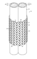
- FIG. 2 is a partial perspective view of the wire harness according to the embodiment.
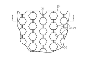
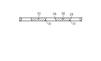
- 1 is a partial plan view of a sheet-shaped molded product according to one embodiment. 4-4 sectional drawing in FIG.
- a wire harness 10 electrically connects two or three or more electric devices (devices), and is installed at a front portion of a vehicle V such as a hybrid vehicle or an electric vehicle.
- the connected inverter 11 is electrically connected to a high-voltage battery 12 installed behind the vehicle V with respect to the inverter 11.
- the wire harness 10 is routed, for example, under the floor of the vehicle V, and has one end connected to the inverter 11 via the connector C1 and the other end connected to the high-voltage battery 12 via the connector C1.
- the inverter 11 is connected to a motor (not shown) for driving wheels, which is a power source for driving the vehicle.
- Inverter 11 generates AC power from DC power of high-voltage battery 12 and supplies the AC power to the motor.
- the high-voltage battery 12 is, for example, a battery that can supply a voltage of 100 volts or more.
- the wire harness 10 includes an electric wire member 20, and the electric wire member 20 includes a plurality of (two in the present embodiment) having a core wire 21 and an insulating coating 22 covering the outer periphery of the core wire 21. ) Is provided.
- the wire harness 10 includes a metal pipe 25, a protector 26, and a resin pipe 27 as various or a series of exterior members through which the electric wire member 20 is inserted.
- the metal pipe 25 is provided so as to cover the electric wire member 20 extending from the high-voltage battery 12 and arranged under the floor of the vehicle V.
- the protector 26 is provided so as to cover a bent portion of the electric wire member 20 closer to the inverter 11 than the metal pipe 25.
- the resin pipe 27 is provided so as to cover the electric wire member 20 between the protector 26 and the inverter 11.
- the resin pipe 27 is provided with a number of discharge holes 28 capable of discharging foreign substances such as sand which have entered between the resin pipe 27 and the electric wire member 20 to the outside.
- the resin pipe 27 of the present embodiment has a honeycomb structure in which the discharge holes 28 are formed in a hexagonal shape. Specifically, the hexagonal discharge holes 28 are arranged at regular intervals along the axial direction which is the extending direction of the electric wire member 20, are arranged at regular intervals along the circumferential direction, and are adjacent to each other in the circumferential direction.
- the resin pipe 27 has a honeycomb structure by providing the corresponding discharge holes 28 shifted in the axial direction.
- the resin pipe 27 is formed by rolling a sheet-like molded product 29 into a tubular shape.
- the resin pipe 27 (sheet-like molded article 29) is formed with a plurality of grooves 30 extending in the axial direction in a tubular state in the circumferential direction.
- the groove 30 is formed on the outer peripheral side of the resin pipe 27.
- the groove 30 is formed for each of the discharge holes 28 arranged in parallel in the circumferential direction.
- the groove portion 30 is formed at a circumferential position corresponding to the circumferential center of each discharge hole 28, and is formed between the discharge holes 28 arranged in the axial direction.
- the groove portion 30 is formed in a V-shape in which the width decreases as the depth increases.
- a chamfered portion 31 having an R-shaped cross section is formed at an end, that is, an opening edge of each discharge hole 28 on the side of the electric wire member 20 (that is, the inner peripheral side of the resin pipe 27).
- the chamfered portion 31 is formed on the entire periphery of the hexagonal contour of each discharge hole 28.
- the resin pipe 27 Since the resin pipe 27 has a honeycomb structure in which the discharge holes 28 are formed in a hexagonal shape, the rigidity of the resin pipe 27 as a whole is kept high while enhancing the ability to discharge foreign substances from the respective discharge holes 28. be able to.
- the resin pipe 27 is formed by rolling the sheet-shaped molded article 29 into a tubular shape, the resin pipe 27 can be easily molded in a molding step, for example, a plurality of sheet-shaped molded articles 29 can be molded together. Can be manufactured in large quantities.
- the resin pipe 27 Since the resin pipe 27 is formed with a plurality of grooves 30 extending in the circumferential direction in a tubular state, the grooves 30 can be easily rolled into a tube. (6) Since the groove portions 30 are formed for each of the discharge holes 28 arranged in the circumferential direction, the resin pipe 27 can be easily rolled into a tubular shape while keeping the rigidity of the resin pipe 27 constant at each portion.
- This embodiment can be implemented with the following modifications.
- the present embodiment and the following modified examples can be implemented in combination with each other within a technically consistent range.
- the example in which the resin pipe 27 is provided with the discharge hole 28 is described.
- a large number of discharge holes may be provided in parallel with another exterior member.
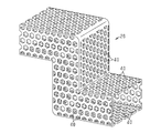
- a large number of discharge holes 40 may be arranged in parallel with the protector 26 as an exterior member.
- the protector 26 is made of a resin material, is formed in a substantially rectangular cylindrical shape through which the electric wire member 20 including the two electric wires 23 can be inserted, and has a bent portion. Regulate along.
- a large number of discharge holes 40 are provided on each surface of the protector 26.
- the discharge hole 40 is formed in a hexagonal shape, and the protector 26 has a honeycomb structure.
- a chamfered portion 41 is formed at the end of each discharge hole 40 on the side of the electric wire member 20, that is, at the opening edge.
- the protector 26 is illustrated as having two right-angled bent portions.
- the protector 26 may have only one bent portion, or may have a non-right-angled bent portion. May be embodied as a protector 26 having the following shape.
- the protector 26 is illustrated as a single unitary molded product that does not deform reversibly, but the present invention is not limited to this. It may be a molded article that can be deformed.
- the protector 26 may be composed of a first molded product 42 and a second molded product 43 having a shape obtained by substantially dividing the protector 26 into two.
- a configuration may be provided having a hinge portion 44 that allows the protector 26 to be opened and closed.
- the hinge part 44 may be a so-called integral hinge.
- the discharge holes 28 and 40 are formed in a hexagonal shape.
- the present invention is not limited to this.
- the discharge holes 28 and 40 may be formed in other shapes such as a circle and a square. That is, the resin pipe 27 and the protector 26 (see FIG. 5) need not have a honeycomb structure.
- the discharge holes 28 and 40 are formed at equal intervals in the entire resin pipe 27 and the protector 26.
- the present invention is not limited thereto, and a part of the resin pipe 27 and the protector 26 (for example, a vehicle) The discharge holes 28 and 40 may be juxtaposed only in the lower part (fixed to V).
- the end portions of the discharge holes 28 and 40 on the wire member 20 side are formed with chamfered portions 31 and 41 having an R-shaped cross section, that is, an outwardly convex curved shape.
- the present invention is not limited to this.
- a chamfer having an inclined surface may be used, or the chamfer may not be formed.
- the resin pipe 27 is formed by rolling the sheet-like molded article 29 into a tubular shape.
- the present invention is not limited to this, and the resin pipe 27 may be formed into a tubular shape from the beginning.
- the groove 30 need not be formed.
- the sheet-like molded article 29 is a resin pipe 27 which is formed into a tubular shape by being rounded, the groove 30 may not be formed.
- the interval in the circumferential direction when the groove 30 is formed may be changed, and may be changed, for example, every two discharge holes 28.
- the groove 30 may have a shape other than the V-shape.
- the electric wire member 20 is configured to include the two electric wires 23, but may be configured to include one or three or more electric wires.
- the electric wire member 20 may further include an electromagnetic shield member surrounding the outer periphery of the electric wire 23.
- the electric wire member 20 may include a braided member in which a plurality of metal wires surrounding the outer periphery of the electric wire 23 are knitted. Is also good.
- an aluminum-based metal material, a copper-based metal material, or the like can be used as a material of the metal strand constituting the braided member.
- the arrangement relationship between the inverter 11 and the high-voltage battery 12 in the vehicle is not limited to the above embodiment, and may be appropriately changed according to the vehicle configuration.
- the inverter 11 and the high-voltage battery 12 are adopted as the electric devices connected by the wire harness 10, but the invention is not limited to this.
- the present invention may be applied to a wire harness that connects the inverter 11 and a wheel driving motor. That is, the present invention is applicable as long as it electrically connects the electric devices mounted on the vehicle.
- each discharge hole 28 may be a through hole that penetrates the sheet-shaped molded product 29 in the thickness direction.
- the discharge hole 28 is advantageous for reducing the weight of the resin pipe 27 in addition to promoting the discharge of solid particles such as sand particles or solid foreign matter from the side surface of the resin pipe 27.
- the large number of discharge holes 28 may be uniformly distributed over the entire sheet-like molded article 29 or at predetermined locations.
- the discharge holes 28 form a plurality of discharge hole rows each extending in the axial direction.
- Each discharge hole row is formed by a plurality of discharge holes 28 arranged in a line in the axial direction.
- the plurality of discharge hole rows are parallel to each other and are separated from each other in the circumferential direction.
- Each discharge hole 28 can have a fixed shape, that is, an undeformed shape.
- the multiple vent holes 28 may all have the same shape and all may have the same dimensions.
- the plurality of discharge holes 28 include a first group of a plurality of first discharge holes having the same shape and the same size, and a plurality of second discharge holes having the same shape and the same size. And a second group of holes comprising holes, wherein the shape and / or dimensions of each of the plurality of second discharge holes may be different from those of the first discharge holes. The same applies to the discharge hole 40 shown in FIG.
- the plurality of grooves 30 may be respectively associated with the plurality of discharge hole arrays.
- the groove 30 may not be formed between two discharge hole rows adjacent in the circumferential direction.
- the sheet-shaped molded article 29 may have a first surface or an outer surface where the groove 30 is formed, and a second surface or an inner surface where the groove 30 is not formed.
- the resin pipe 27 shown in FIG. 2 and the protector 26 shown in FIG. 5 may be an electrically insulating cylindrical exterior member.
- the resin pipe 27 shown in FIG. 2 is an example of a linear tubular exterior member.
- the resin pipe 27 may regulate the wiring route of the electric wire member 20 over the length of the resin pipe 27.
- the protector 26 shown in FIG. 5 is an example of a cylindrical exterior member having one or a plurality of bent portions. The protector 26 may regulate the wiring route of the electric wire member 20 over the length of the protector 26.
Landscapes
- Engineering & Computer Science (AREA)
- General Engineering & Computer Science (AREA)
- Mechanical Engineering (AREA)
- Architecture (AREA)
- Civil Engineering (AREA)
- Structural Engineering (AREA)
- Details Of Indoor Wiring (AREA)
- Insulated Conductors (AREA)
- Protection Of Pipes Against Damage, Friction, And Corrosion (AREA)
Abstract
ワイヤハーネス10は、電線部材20と、電線部材20が挿通される樹脂パイプ27とを備える。樹脂パイプ27には、該樹脂パイプ27と電線部材20との間に侵入した異物を外部に排出可能な多数の排出孔28が並設される。
Description
本発明は、ワイヤハーネス、及び外装部材に関するものである。
従来、ハイブリッド車や電気自動車等の車両に用いられるワイヤハーネスとしては、電線部材の外側がコルゲートチューブや樹脂パイプ等の外装部材で覆われたワイヤハーネスが知られている。そして、このようなワイヤハーネスは、車両床下等に配索されて外部に晒される場合があるため、各種外装部材に覆われるとともに外装部材同士の間に発泡部材を介在させて外装部材と電線部材との間に砂等の異物が侵入することを防止しようとしたものがある(例えば、特許文献1参照)。このような構成では、電線部材が砂等の異物と長期的に擦れ合って傷付くといったことが低減される。
しかしながら、上記のように発泡部材等の別部材を用いて外装部材と電線部材との間に砂等の異物が侵入することを防止する構成では、構成が複雑化して部品点数や組み付け工数が増大する等、コストの増大を招くことになる。そのため、簡単な構成で電線部材が傷付きにくいワイヤハーネスが求められている。
本発明は、上記課題を解決するためになされたものであって、その目的は、簡単な構成で電線部材を良好に保護することができるワイヤハーネス、及び外装部材を提供することにある。
上記課題を解決するワイヤハーネスは、電線部材と、前記電線部材が挿通される外装部材とを備えたワイヤハーネスであって、前記外装部材には、該外装部材と前記電線部材との間に侵入した異物を外部に排出可能な多数の排出孔が並設される。
同構成によれば、外装部材には、該外装部材と電線部材との間に侵入した異物を外部に排出可能な多数の排出孔が並設されるため、排出孔から異物を排出することができ、外装部材と電線部材との間に異物が保持されてしまうことを防ぐことができる。よって、電線部材が砂等の異物と長期的に擦れ合って傷付くといったことが防止され、簡単な構成で電線部材を良好に保護することができる。
前記外装部材は、各排出孔が六角形に形成されてハニカム構造とされてよい。
同構成によれば、外装部材は、各排出孔が六角形に形成されてハニカム構造とされるため、各排出孔からの異物の排出能力を高めながらも、外装部材全体の剛性を高く保つことができる。
同構成によれば、外装部材は、各排出孔が六角形に形成されてハニカム構造とされるため、各排出孔からの異物の排出能力を高めながらも、外装部材全体の剛性を高く保つことができる。
各排出孔の前記電線部材側の端部には面取り部が形成されてよい。
同構成によれば、各排出孔の前記電線部材側の端部には面取り部が形成されるため、各排出孔の電線部材側の端部に電線部材が擦れて傷付くことが低減される。
同構成によれば、各排出孔の前記電線部材側の端部には面取り部が形成されるため、各排出孔の電線部材側の端部に電線部材が擦れて傷付くことが低減される。
前記外装部材は、シート状成形品が丸められて管状とされたものであってよい。
同構成によれば、前記外装部材は、シート状成形品が丸められて管状とされたものであるため、成形工程で例えば複数個分のシート状成形品をまとめて成形することができるなど、容易に大量に製造することができる。
同構成によれば、前記外装部材は、シート状成形品が丸められて管状とされたものであるため、成形工程で例えば複数個分のシート状成形品をまとめて成形することができるなど、容易に大量に製造することができる。
前記外装部材には、管状とされた状態で軸方向に延びる溝部が周方向に複数形成されてよい。
同構成によれば、前記外装部材には、管状とされた状態で軸方向に延びる溝部が周方向に複数形成されるため、容易に丸めて管状とすることができる。
同構成によれば、前記外装部材には、管状とされた状態で軸方向に延びる溝部が周方向に複数形成されるため、容易に丸めて管状とすることができる。
前記溝部は、周方向に並設される前記排出孔毎に形成されてよい。
同構成によれば、前記溝部は、周方向に並設される排出孔毎に形成されるため、外装部材の剛性を各部位で一定としながら、容易に丸めて管状とすることができる。
同構成によれば、前記溝部は、周方向に並設される排出孔毎に形成されるため、外装部材の剛性を各部位で一定としながら、容易に丸めて管状とすることができる。
上記課題を解決する外装部材は、電線部材が挿通される外装部材であって、前記外装部材と前記電線部材との間に侵入した異物を前記外装部材の外部に排出可能な多数の排出孔が並設される。
同構成によれば、外装部材には、当該外装部材と電線部材との間に侵入した異物を外部に排出可能な多数の孔が並設されるため、外装部材と電線部材との間に異物が保持されてしまうことを防ぐことができる。よって、電線部材が砂等の異物と長期的に擦れ合って傷付くといったことが防止され、簡単な構成で電線部材を良好に保護することができる。
本発明のワイヤハーネス、及び外装部材によれば、簡単な構成で電線部材を良好に保護することができる。
以下、ワイヤハーネスの一実施形態について、図1~図4に従って説明する。なお、各図面では、説明の便宜上、構成の一部を誇張又は簡略化して示す場合がある。また、各部分の寸法比率についても、実際とは異なる場合がある。
図1に示すようにワイヤハーネス10は、2個又は3個以上の電気機器(機器)を電気的に接続するものであって、例えば、ハイブリッド車や電気自動車等の車両Vの前部に設置されたインバータ11と、そのインバータ11よりも車両Vの後方に設置された高圧バッテリ12とを電気的に接続する。ワイヤハーネス10は、例えば、車両Vの床下等を通るように配索され、その一端がコネクタC1を介してインバータ11に接続され、他端がコネクタC1を介して高圧バッテリ12に接続される。インバータ11は、車両走行の動力源となる車輪駆動用のモータ(図示略)と接続される。インバータ11は、高圧バッテリ12の直流電力から交流電力を生成し、その交流電力をモータに供給する。高圧バッテリ12は、例えば、百ボルト以上の電圧を供給可能なバッテリである。
図2に示すように、ワイヤハーネス10は、電線部材20を備え、該電線部材20は、芯線21と該芯線21の外周を被覆する絶縁被覆22とを有する複数本(本実施形態では2本)の電線23を備える。
また、図1に示すように、ワイヤハーネス10は、前記電線部材20が挿通される種々のまたは一連の外装部材として金属パイプ25とプロテクタ26と樹脂パイプ27とを備える。金属パイプ25は、高圧バッテリ12から延びて車両Vの床下に配索される電線部材20を覆うように設けられている。プロテクタ26は、金属パイプ25よりもインバータ11側の電線部材20の屈曲部位を覆うように設けられている。樹脂パイプ27は、プロテクタ26とインバータ11との間の電線部材20を覆うように設けられている。
ここで、図2に示すように、樹脂パイプ27には、該樹脂パイプ27と前記電線部材20との間に侵入した砂等の異物を外部に排出可能な多数の排出孔28が並設されている。本実施形態の樹脂パイプ27は、排出孔28が六角形に形成されてハニカム構造とされている。詳しくは、六角形の排出孔28は、電線部材20の延在方向である軸方向に沿って等間隔で並設されるとともに、周方向に沿って等間隔で並設され、周方向に隣り合う排出孔28が軸方向にずれて設けられることで樹脂パイプ27がハニカム構造とされている。
また、図2~図4に示すように、樹脂パイプ27は、シート状成形品29が丸められて管状とされたものである。樹脂パイプ27(シート状成形品29)には、管状とされた状態で軸方向に延びる溝部30が周方向に複数形成されている。溝部30は、樹脂パイプ27の外周側に形成されている。溝部30は、周方向に並設される排出孔28毎に形成されている。溝部30は、各排出孔28の周方向中心と対応した周方向位置に形成され、軸方向に並設される排出孔28同士の間に形成されている。図4に示すように、溝部30は、深くなるほど幅が狭くなるV字形状に形成されている。
また、図4に示すように、各排出孔28の電線部材20側(すなわち樹脂パイプ27の内周側)の端部すなわち開口縁には断面R形状の面取り部31が形成されている。面取り部31は、各排出孔28の六角形輪郭の全周に形成されている。
次に、上記のように構成されたワイヤハーネス10の作用について説明する。
例えば、車両Vの走行中等では、回転するタイヤによる跳ね上げや走行風等によって地面の砂等の異物が舞い上げられてワイヤハーネス10に掛かることがある。そして、樹脂パイプ27と電線部材20との間に砂等の異物が入り込むこともあるが、それら異物は排出孔28から排出される。
例えば、車両Vの走行中等では、回転するタイヤによる跳ね上げや走行風等によって地面の砂等の異物が舞い上げられてワイヤハーネス10に掛かることがある。そして、樹脂パイプ27と電線部材20との間に砂等の異物が入り込むこともあるが、それら異物は排出孔28から排出される。
次に、上記実施形態の効果を以下に記載する。
(1)樹脂パイプ27には、該樹脂パイプ27と電線部材20との間に侵入した異物を外部に排出可能な多数の排出孔28が並設されるため、排出孔28から異物を排出することができ、樹脂パイプ27と電線部材20との間に異物が保持されてしまうことを防ぐことができる。よって、電線部材20が砂等の異物と長期的に擦れ合って傷付くといったことが防止され、簡単な構成で電線部材20を良好に保護することができる。
(1)樹脂パイプ27には、該樹脂パイプ27と電線部材20との間に侵入した異物を外部に排出可能な多数の排出孔28が並設されるため、排出孔28から異物を排出することができ、樹脂パイプ27と電線部材20との間に異物が保持されてしまうことを防ぐことができる。よって、電線部材20が砂等の異物と長期的に擦れ合って傷付くといったことが防止され、簡単な構成で電線部材20を良好に保護することができる。
(2)樹脂パイプ27は、各排出孔28が六角形に形成されてハニカム構造とされるため、各排出孔28からの異物の排出能力を高めながらも、樹脂パイプ27全体の剛性を高く保つことができる。
(3)各排出孔28の電線部材20側の端部には面取り部31が形成されるため、各排出孔28の電線部材20側の端部に電線部材20が擦れて傷付くことが低減される。
(4)樹脂パイプ27は、シート状成形品29が丸められて管状とされたものであるため、成形工程で例えば複数個分のシート状成形品29をまとめて成形することができるなど、容易に大量に製造することができる。
(4)樹脂パイプ27は、シート状成形品29が丸められて管状とされたものであるため、成形工程で例えば複数個分のシート状成形品29をまとめて成形することができるなど、容易に大量に製造することができる。
(5)樹脂パイプ27には、管状とされた状態で軸方向に延びる溝部30が周方向に複数形成されるため、容易に丸めて管状とすることができる。
(6)溝部30は、周方向に並設される排出孔28毎に形成されるため、樹脂パイプ27の剛性を各部位で一定としながら、容易に丸めて管状とすることができる。
(6)溝部30は、周方向に並設される排出孔28毎に形成されるため、樹脂パイプ27の剛性を各部位で一定としながら、容易に丸めて管状とすることができる。
本実施形態は、以下のように変更して実施することができる。本実施形態及び以下の変更例は、技術的に矛盾しない範囲で互いに組み合わせて実施することができる。
・上記実施形態では、樹脂パイプ27に排出孔28が設けられた例としたが、他の外装部材に多数の排出孔を並設して実施してもよい。
・上記実施形態では、樹脂パイプ27に排出孔28が設けられた例としたが、他の外装部材に多数の排出孔を並設して実施してもよい。
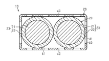
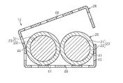
具体的には、例えば、図5及び図6に示すように、外装部材としてのプロテクタ26に多数の排出孔40を並設して実施してもよい。このプロテクタ26は、樹脂材よりなり、2本の電線23を備えた電線部材20が挿通可能な略四角筒状に形成されるとともに屈曲部を有し、電線部材20の経路をプロテクタ26の形状に沿って規制する。そして、プロテクタ26の各面には多数の排出孔40が並設されている。また、この例においても、排出孔40は六角形に形成されてプロテクタ26はハニカム構造とされている。また、この例においても、図6に示すように、各排出孔40の電線部材20側の端部すなわち開口縁には面取り部41が形成されている。このようにしても、上記実施形態の効果(1)~(3)と同様の効果を得ることができる。なお、図5では、プロテクタ26が2つの直角な屈曲部を有するように図示しているが、勿論、1つの屈曲部しか有していないものや、直角でない屈曲部を有したもの等、他の形状のプロテクタ26として具体化してもよい。
また、この例(図5及び図6参照)では、プロテクタ26を単一で可逆的に変形しない一体成形品として図示したが、これに限定されず、複数の成形品で構成したり、可逆的に変形可能な成形品としてもよい。
具体的には、例えば、図7に示すように、プロテクタ26を略2分割した形状の第1成形品42と第2成形品43とから構成してもよい。
また、例えば、図8に示すように、プロテクタ26を開閉変形可能とするヒンジ部44を有した構成としてもよい。ヒンジ部44は、いわゆるインテグラルヒンジであってよい。
また、例えば、図8に示すように、プロテクタ26を開閉変形可能とするヒンジ部44を有した構成としてもよい。ヒンジ部44は、いわゆるインテグラルヒンジであってよい。
・上記実施形態では、排出孔28,40が六角形に形成されるとしたが、これに限定されず、例えば、円形や四角形等の他の形に形成してもよい。すなわち、樹脂パイプ27やプロテクタ26(図5参照)をハニカム構造としなくてもよい。また、上記実施形態では排出孔28,40が等間隔で樹脂パイプ27やプロテクタ26の全体に形成されるとしたが、これに限定されず、樹脂パイプ27やプロテクタ26の一部(例えば、車両Vに固定された状態で下部)にのみ排出孔28,40が並設された構成としてもよい。
・上記実施形態では、各排出孔28,40の電線部材20側の端部すなわち開口縁には断面R形状の、すなわち外向きに凸曲面状の、面取り部31,41が形成されるとしたが、これに限定されず、例えば、傾斜面状の面取り部としてもよいし、面取り部を形成しなくてもよい。
・上記実施形態では、樹脂パイプ27は、シート状成形品29が丸められて管状とされたものであるとしたが、これに限定されず、最初から管状に成形されたものとしてもよい。また、特にこのような場合、溝部30を形成しなくてもよい。また、シート状成形品29が丸められて管状とされた樹脂パイプ27であっても、溝部30を形成しなくてもよい。また、溝部30を形成する場合の周方向の間隔は、変更してもよく、例えば排出孔28の2つ置き毎等に変更してもよい。また、溝部30は、V字形状以外の形状としてもよい。
・上記実施形態では、電線部材20は、2本の電線23を備えた構成としたが、1本や3本以上の電線を備えた構成としてもよい。また、電線部材20は、更に電線23の外周を包囲する電磁シールド部材を備えた構成としてもよく、例えば電線23の外周を包囲する複数の金属素線が編成された編組部材を備えた構成としてもよい。なお、編組部材を構成する金属素線の材料は、アルミニウム系金属材料や銅系金属材料等を用いることができる。
・車両におけるインバータ11と高圧バッテリ12の配置関係は、上記実施形態に限定されるものではなく、車両構成に応じて適宜変更してもよい。
・上記実施形態では、ワイヤハーネス10によって接続される電気機器としてインバータ11及び高圧バッテリ12を採用したが、これに限定されない。例えば、インバータ11と車輪駆動用のモータとを接続するワイヤハーネスに採用してもよい。すなわち、車両に搭載される電気機器間を電気的に接続するものであれば適用可能である。
・上記実施形態では、ワイヤハーネス10によって接続される電気機器としてインバータ11及び高圧バッテリ12を採用したが、これに限定されない。例えば、インバータ11と車輪駆動用のモータとを接続するワイヤハーネスに採用してもよい。すなわち、車両に搭載される電気機器間を電気的に接続するものであれば適用可能である。
・図4に示した例のように、各排出孔28は、シート状成形品29を厚さ方向に貫通する貫通孔であってよい。排出孔28は、樹脂パイプ27の側面から、砂粒などの固形粒または固形異物を排出するのを促進するのに加え、樹脂パイプ27の軽量化に有利である。図5に示した排出孔40についても同様である。
・図2に示した例のように、多数の排出孔28は、シート状成形品29の全体または所定の局所に、一様に分散して設けられてよい。図5の排出孔40についても同様である。
・図2に示した例では、排出孔28は、各々が軸方向に延在する複数の排出孔列を形成する。各排出孔列は、軸方向に一列に並んだ複数の排出孔28によって形成される。複数の排出孔列は、互いに平行で、かつ、周方向に互いに離間している。図5に示した排出孔40についても同様である。
・図2に示した例では、排出孔28は、各々が軸方向に延在する複数の排出孔列を形成する。各排出孔列は、軸方向に一列に並んだ複数の排出孔28によって形成される。複数の排出孔列は、互いに平行で、かつ、周方向に互いに離間している。図5に示した排出孔40についても同様である。
・各排出孔28は一定形状すなわち不変形状を有することができる。図示した実施形態では、多数の排出孔28は、すべてが同じ形状を有してよく、すべてが同じ寸法を有してよい。別の或る例では、多数の排出孔28は、同じ形状と同じ寸法を有する複数の第1の排出孔からなる第1の孔群と、同じ形状と同じ寸法を有する複数の第2の排出孔からなる第2の孔群とを含んでよく、前記複数の第2の排出孔の各々の形状および/または寸法が、前記第1の排出孔のものと異なってよい。図5に示した排出孔40についても同様である。
・図2に示した例のように、複数の溝部30は、複数の排出孔列にそれぞれ対応付けられてよい。シート状成形品29において、周方向に隣り合う2つの排出孔列の間には、溝部30は形成されなくてよい。
・図2に示した例のように、シート状成形品29は、溝部30が形成された第1面または外面と、溝部30が形成されていない第2面または内面とを有してよい。
・図2に示した樹脂パイプ27および図5に示したプロテクタ26は、電気絶縁性の筒状外装部材であってよい。図2に示した樹脂パイプ27は、直線的筒状の外装部材の一例である。樹脂パイプ27は、当該樹脂パイプ27の長さにわたって、電線部材20の配索経路を規制してよい。図5に示したプロテクタ26は、1つまたは複数の屈曲部を有する筒状外装部材の一例である。プロテクタ26は、当該プロテクタ26の長さにわたって、電線部材20の配索経路を規制してよい。
・図2に示した樹脂パイプ27および図5に示したプロテクタ26は、電気絶縁性の筒状外装部材であってよい。図2に示した樹脂パイプ27は、直線的筒状の外装部材の一例である。樹脂パイプ27は、当該樹脂パイプ27の長さにわたって、電線部材20の配索経路を規制してよい。図5に示したプロテクタ26は、1つまたは複数の屈曲部を有する筒状外装部材の一例である。プロテクタ26は、当該プロテクタ26の長さにわたって、電線部材20の配索経路を規制してよい。
本発明がその技術的思想から逸脱しない範囲で他の特有の形態で具体化されてもよいということは当業者にとって明らかであろう。例えば、実施形態(あるいはその1つ又は複数の態様)において説明した部品のうちの一部を省略したり、いくつかの部品を組合せてもよい。本発明の範囲は、添付の請求の範囲を参照して、請求の範囲が権利を与えられる均等物の全範囲と共に確定されるべきである。
10…ワイヤハーネス
20…電線部材
26…プロテクタ(外装部材)
27…樹脂パイプ(外装部材)
28,40…排出孔
29…シート状成形品
30…溝部
31,41…面取り部
20…電線部材
26…プロテクタ(外装部材)
27…樹脂パイプ(外装部材)
28,40…排出孔
29…シート状成形品
30…溝部
31,41…面取り部
Claims (7)
- 電線部材と、
前記電線部材が挿通される外装部材と
を備えたワイヤハーネスであって、
前記外装部材には、該外装部材と前記電線部材との間に侵入した異物を外部に排出可能な多数の排出孔が並設されたワイヤハーネス。 - 前記外装部材は、各排出孔が六角形に形成されてハニカム構造とされた請求項1に記載のワイヤハーネス。
- 各排出孔の前記電線部材側の端部には面取り部が形成された請求項1又は2に記載のワイヤハーネス。
- 前記外装部材は、シート状成形品が丸められて管状とされたものである請求項1~3の何れか1項に記載のワイヤハーネス。
- 前記外装部材には、管状とされた状態で軸方向に延びる溝部が周方向に複数形成された請求項4に記載のワイヤハーネス。
- 前記溝部は、周方向に並設される前記排出孔毎に形成された請求項5に記載のワイヤハーネス。
- 電線部材が挿通される外装部材であって、
前記外装部材と前記電線部材との間に侵入した異物を前記外装部材の外部に排出可能な多数の排出孔が並設された外装部材。
Priority Applications (2)
| Application Number | Priority Date | Filing Date | Title |
|---|---|---|---|
| US17/281,449 US11450453B2 (en) | 2018-10-05 | 2019-07-18 | Wire harness, and exterior member |
| CN201980064830.1A CN112805893B (zh) | 2018-10-05 | 2019-07-18 | 线束及外装构件 |
Applications Claiming Priority (2)
| Application Number | Priority Date | Filing Date | Title |
|---|---|---|---|
| JP2018190226A JP7006560B2 (ja) | 2018-10-05 | 2018-10-05 | ワイヤハーネス、及び外装部材 |
| JP2018-190226 | 2018-10-05 |
Publications (1)
| Publication Number | Publication Date |
|---|---|
| WO2020070950A1 true WO2020070950A1 (ja) | 2020-04-09 |
Family
ID=70055459
Family Applications (1)
| Application Number | Title | Priority Date | Filing Date |
|---|---|---|---|
| PCT/JP2019/028286 Ceased WO2020070950A1 (ja) | 2018-10-05 | 2019-07-18 | ワイヤハーネス、及び外装部材 |
Country Status (4)
| Country | Link |
|---|---|
| US (1) | US11450453B2 (ja) |
| JP (1) | JP7006560B2 (ja) |
| CN (1) | CN112805893B (ja) |
| WO (1) | WO2020070950A1 (ja) |
Families Citing this family (1)
| Publication number | Priority date | Publication date | Assignee | Title |
|---|---|---|---|---|
| JP7794009B2 (ja) * | 2022-02-15 | 2026-01-06 | 住友電装株式会社 | ワイヤハーネス |
Citations (4)
| Publication number | Priority date | Publication date | Assignee | Title |
|---|---|---|---|---|
| JP2002186131A (ja) * | 2000-12-15 | 2002-06-28 | Auto Network Gijutsu Kenkyusho:Kk | 車両用電線プロテクタ |
| JP2009296743A (ja) * | 2008-06-03 | 2009-12-17 | Sumitomo Wiring Syst Ltd | ワイヤハーネスの排水構造 |
| JP2015180168A (ja) * | 2014-03-20 | 2015-10-08 | 住友電装株式会社 | ワイヤハーネス用プロテクタおよびワイヤハーネス |
| JP2017158299A (ja) * | 2016-03-01 | 2017-09-07 | 株式会社オートネットワーク技術研究所 | 熱収縮チューブおよびそれを用いたワイヤハーネスの結束構造 |
Family Cites Families (7)
| Publication number | Priority date | Publication date | Assignee | Title |
|---|---|---|---|---|
| CN201398040Y (zh) * | 2009-04-06 | 2010-02-03 | 许福章 | 线缆保护套 |
| US8704093B2 (en) * | 2010-12-20 | 2014-04-22 | Panduit Corp. | Shielded wireway systems |
| CN202775203U (zh) * | 2012-06-28 | 2013-03-13 | 淮南师范学院 | 有孔座椅 |
| CN202893048U (zh) * | 2012-11-19 | 2013-04-24 | 瓮福(集团)有限责任公司 | 一种改进的带式压滤机挤压辊筒 |
| JP5800844B2 (ja) * | 2013-03-13 | 2015-10-28 | 株式会社椿本チエイン | チューブ型ケーブル類保護案内装置 |
| JP6372417B2 (ja) | 2015-04-14 | 2018-08-15 | 住友電装株式会社 | 電池配線モジュール |
| EP3447868B1 (de) * | 2015-08-28 | 2026-01-21 | Niedax GmbH & Co. KG | Kabelkanalrinne welche eingestanzte befestigungsstellen mit sollbruchstellen aufweist und verfahren zur herstellung einer solchen kabelkanarinne |
-
2018
- 2018-10-05 JP JP2018190226A patent/JP7006560B2/ja active Active
-
2019
- 2019-07-18 US US17/281,449 patent/US11450453B2/en active Active
- 2019-07-18 CN CN201980064830.1A patent/CN112805893B/zh active Active
- 2019-07-18 WO PCT/JP2019/028286 patent/WO2020070950A1/ja not_active Ceased
Patent Citations (4)
| Publication number | Priority date | Publication date | Assignee | Title |
|---|---|---|---|---|
| JP2002186131A (ja) * | 2000-12-15 | 2002-06-28 | Auto Network Gijutsu Kenkyusho:Kk | 車両用電線プロテクタ |
| JP2009296743A (ja) * | 2008-06-03 | 2009-12-17 | Sumitomo Wiring Syst Ltd | ワイヤハーネスの排水構造 |
| JP2015180168A (ja) * | 2014-03-20 | 2015-10-08 | 住友電装株式会社 | ワイヤハーネス用プロテクタおよびワイヤハーネス |
| JP2017158299A (ja) * | 2016-03-01 | 2017-09-07 | 株式会社オートネットワーク技術研究所 | 熱収縮チューブおよびそれを用いたワイヤハーネスの結束構造 |
Also Published As
| Publication number | Publication date |
|---|---|
| JP2020061822A (ja) | 2020-04-16 |
| US20220005627A1 (en) | 2022-01-06 |
| CN112805893A (zh) | 2021-05-14 |
| JP7006560B2 (ja) | 2022-01-24 |
| CN112805893B (zh) | 2023-08-15 |
| US11450453B2 (en) | 2022-09-20 |
Similar Documents
| Publication | Publication Date | Title |
|---|---|---|
| EP2711937B1 (en) | Shielding wire | |
| JP6200238B2 (ja) | ワイヤハーネス | |
| JP3800578B2 (ja) | 改良型複合碍子 | |
| EP2889973B1 (en) | Wire harness exterior member and wire harness | |
| JP2012243550A (ja) | 高圧電線、及び高圧電線の製造方法 | |
| US20140206223A1 (en) | Earth terminal mounted tool | |
| JP2020058095A (ja) | ワイヤハーネス | |
| WO2020070950A1 (ja) | ワイヤハーネス、及び外装部材 | |
| JP6080341B2 (ja) | ワイヤハーネス | |
| WO2017014017A1 (ja) | シールド導電路 | |
| DE102018205110B4 (de) | Neutralisationsvorrichtung für fahrzeuge | |
| WO2021171968A1 (ja) | 外装部材、及びワイヤハーネス | |
| US9840210B2 (en) | Wire harness | |
| US9586539B2 (en) | Underfloor shielded harness | |
| JP2021032340A (ja) | パイプおよびワイヤハーネス | |
| US20220189655A1 (en) | Wire harness | |
| JP6950021B2 (ja) | プロテクタ及びワイヤハーネス | |
| WO2023157735A1 (ja) | ワイヤハーネス | |
| JP7264464B2 (ja) | タイヤホイール | |
| JP5629799B2 (ja) | 車体床下ワイヤハーネスの保護部材 | |
| JP7816212B2 (ja) | 電線固定部材 | |
| US12304400B2 (en) | Wire harness with first and second path restrictors and formed air layer | |
| JP7564171B2 (ja) | ノイズ低減シートおよびワイヤハーネス | |
| JP2020053377A (ja) | 扁平電線 | |
| JP6762686B2 (ja) | アース配索材 |
Legal Events
| Date | Code | Title | Description |
|---|---|---|---|
| 121 | Ep: the epo has been informed by wipo that ep was designated in this application |
Ref document number: 19868275 Country of ref document: EP Kind code of ref document: A1 |
|
| NENP | Non-entry into the national phase |
Ref country code: DE |
|
| 122 | Ep: pct application non-entry in european phase |
Ref document number: 19868275 Country of ref document: EP Kind code of ref document: A1 |